EP3288350A1 - Flexible light engine with bus bars and interconnectors - Google Patents
Flexible light engine with bus bars and interconnectors Download PDFInfo
- Publication number
- EP3288350A1 EP3288350A1 EP17179460.5A EP17179460A EP3288350A1 EP 3288350 A1 EP3288350 A1 EP 3288350A1 EP 17179460 A EP17179460 A EP 17179460A EP 3288350 A1 EP3288350 A1 EP 3288350A1
- Authority
- EP
- European Patent Office
- Prior art keywords
- metallic
- laminate sheet
- bus bars
- interconnectors
- upper laminate
- Prior art date
- Legal status (The legal status is an assumption and is not a legal conclusion. Google has not performed a legal analysis and makes no representation as to the accuracy of the status listed.)
- Granted
Links
Images



Classifications
-
- F—MECHANICAL ENGINEERING; LIGHTING; HEATING; WEAPONS; BLASTING
- F21—LIGHTING
- F21S—NON-PORTABLE LIGHTING DEVICES; SYSTEMS THEREOF; VEHICLE LIGHTING DEVICES SPECIALLY ADAPTED FOR VEHICLE EXTERIORS
- F21S4/00—Lighting devices or systems using a string or strip of light sources
- F21S4/20—Lighting devices or systems using a string or strip of light sources with light sources held by or within elongate supports
- F21S4/22—Lighting devices or systems using a string or strip of light sources with light sources held by or within elongate supports flexible or deformable, e.g. into a curved shape
-
- H—ELECTRICITY
- H05—ELECTRIC TECHNIQUES NOT OTHERWISE PROVIDED FOR
- H05K—PRINTED CIRCUITS; CASINGS OR CONSTRUCTIONAL DETAILS OF ELECTRIC APPARATUS; MANUFACTURE OF ASSEMBLAGES OF ELECTRICAL COMPONENTS
- H05K1/00—Printed circuits
- H05K1/18—Printed circuits structurally associated with non-printed electric components
- H05K1/189—Printed circuits structurally associated with non-printed electric components characterised by the use of flexible or folded printed circuits
-
- F—MECHANICAL ENGINEERING; LIGHTING; HEATING; WEAPONS; BLASTING
- F21—LIGHTING
- F21K—NON-ELECTRIC LIGHT SOURCES USING LUMINESCENCE; LIGHT SOURCES USING ELECTROCHEMILUMINESCENCE; LIGHT SOURCES USING CHARGES OF COMBUSTIBLE MATERIAL; LIGHT SOURCES USING SEMICONDUCTOR DEVICES AS LIGHT-GENERATING ELEMENTS; LIGHT SOURCES NOT OTHERWISE PROVIDED FOR
- F21K9/00—Light sources using semiconductor devices as light-generating elements, e.g. using light-emitting diodes [LED] or lasers
- F21K9/90—Methods of manufacture
-
- F—MECHANICAL ENGINEERING; LIGHTING; HEATING; WEAPONS; BLASTING
- F21—LIGHTING
- F21K—NON-ELECTRIC LIGHT SOURCES USING LUMINESCENCE; LIGHT SOURCES USING ELECTROCHEMILUMINESCENCE; LIGHT SOURCES USING CHARGES OF COMBUSTIBLE MATERIAL; LIGHT SOURCES USING SEMICONDUCTOR DEVICES AS LIGHT-GENERATING ELEMENTS; LIGHT SOURCES NOT OTHERWISE PROVIDED FOR
- F21K9/00—Light sources using semiconductor devices as light-generating elements, e.g. using light-emitting diodes [LED] or lasers
- F21K9/20—Light sources comprising attachment means
-
- F—MECHANICAL ENGINEERING; LIGHTING; HEATING; WEAPONS; BLASTING
- F21—LIGHTING
- F21S—NON-PORTABLE LIGHTING DEVICES; SYSTEMS THEREOF; VEHICLE LIGHTING DEVICES SPECIALLY ADAPTED FOR VEHICLE EXTERIORS
- F21S4/00—Lighting devices or systems using a string or strip of light sources
- F21S4/20—Lighting devices or systems using a string or strip of light sources with light sources held by or within elongate supports
- F21S4/22—Lighting devices or systems using a string or strip of light sources with light sources held by or within elongate supports flexible or deformable, e.g. into a curved shape
- F21S4/24—Lighting devices or systems using a string or strip of light sources with light sources held by or within elongate supports flexible or deformable, e.g. into a curved shape of ribbon or tape form, e.g. LED tapes
-
- F—MECHANICAL ENGINEERING; LIGHTING; HEATING; WEAPONS; BLASTING
- F21—LIGHTING
- F21V—FUNCTIONAL FEATURES OR DETAILS OF LIGHTING DEVICES OR SYSTEMS THEREOF; STRUCTURAL COMBINATIONS OF LIGHTING DEVICES WITH OTHER ARTICLES, NOT OTHERWISE PROVIDED FOR
- F21V17/00—Fastening of component parts of lighting devices, e.g. shades, globes, refractors, reflectors, filters, screens, grids or protective cages
- F21V17/10—Fastening of component parts of lighting devices, e.g. shades, globes, refractors, reflectors, filters, screens, grids or protective cages characterised by specific fastening means or way of fastening
- F21V17/101—Fastening of component parts of lighting devices, e.g. shades, globes, refractors, reflectors, filters, screens, grids or protective cages characterised by specific fastening means or way of fastening permanently, e.g. welding, gluing or riveting
-
- F—MECHANICAL ENGINEERING; LIGHTING; HEATING; WEAPONS; BLASTING
- F21—LIGHTING
- F21V—FUNCTIONAL FEATURES OR DETAILS OF LIGHTING DEVICES OR SYSTEMS THEREOF; STRUCTURAL COMBINATIONS OF LIGHTING DEVICES WITH OTHER ARTICLES, NOT OTHERWISE PROVIDED FOR
- F21V19/00—Fastening of light sources or lamp holders
- F21V19/001—Fastening of light sources or lamp holders the light sources being semiconductors devices, e.g. LEDs
- F21V19/003—Fastening of light source holders, e.g. of circuit boards or substrates holding light sources
-
- F—MECHANICAL ENGINEERING; LIGHTING; HEATING; WEAPONS; BLASTING
- F21—LIGHTING
- F21V—FUNCTIONAL FEATURES OR DETAILS OF LIGHTING DEVICES OR SYSTEMS THEREOF; STRUCTURAL COMBINATIONS OF LIGHTING DEVICES WITH OTHER ARTICLES, NOT OTHERWISE PROVIDED FOR
- F21V23/00—Arrangement of electric circuit elements in or on lighting devices
- F21V23/06—Arrangement of electric circuit elements in or on lighting devices the elements being coupling devices, e.g. connectors
-
- F—MECHANICAL ENGINEERING; LIGHTING; HEATING; WEAPONS; BLASTING
- F21—LIGHTING
- F21V—FUNCTIONAL FEATURES OR DETAILS OF LIGHTING DEVICES OR SYSTEMS THEREOF; STRUCTURAL COMBINATIONS OF LIGHTING DEVICES WITH OTHER ARTICLES, NOT OTHERWISE PROVIDED FOR
- F21V29/00—Protecting lighting devices from thermal damage; Cooling or heating arrangements specially adapted for lighting devices or systems
- F21V29/50—Cooling arrangements
- F21V29/70—Cooling arrangements characterised by passive heat-dissipating elements, e.g. heat-sinks
-
- H—ELECTRICITY
- H05—ELECTRIC TECHNIQUES NOT OTHERWISE PROVIDED FOR
- H05K—PRINTED CIRCUITS; CASINGS OR CONSTRUCTIONAL DETAILS OF ELECTRIC APPARATUS; MANUFACTURE OF ASSEMBLAGES OF ELECTRICAL COMPONENTS
- H05K3/00—Apparatus or processes for manufacturing printed circuits
- H05K3/10—Apparatus or processes for manufacturing printed circuits in which conductive material is applied to the insulating support in such a manner as to form the desired conductive pattern
- H05K3/20—Apparatus or processes for manufacturing printed circuits in which conductive material is applied to the insulating support in such a manner as to form the desired conductive pattern by affixing prefabricated conductor pattern
- H05K3/202—Apparatus or processes for manufacturing printed circuits in which conductive material is applied to the insulating support in such a manner as to form the desired conductive pattern by affixing prefabricated conductor pattern using self-supporting metal foil pattern
-
- F—MECHANICAL ENGINEERING; LIGHTING; HEATING; WEAPONS; BLASTING
- F21—LIGHTING
- F21K—NON-ELECTRIC LIGHT SOURCES USING LUMINESCENCE; LIGHT SOURCES USING ELECTROCHEMILUMINESCENCE; LIGHT SOURCES USING CHARGES OF COMBUSTIBLE MATERIAL; LIGHT SOURCES USING SEMICONDUCTOR DEVICES AS LIGHT-GENERATING ELEMENTS; LIGHT SOURCES NOT OTHERWISE PROVIDED FOR
- F21K9/00—Light sources using semiconductor devices as light-generating elements, e.g. using light-emitting diodes [LED] or lasers
- F21K9/20—Light sources comprising attachment means
- F21K9/27—Retrofit light sources for lighting devices with two fittings for each light source, e.g. for substitution of fluorescent tubes
-
- F—MECHANICAL ENGINEERING; LIGHTING; HEATING; WEAPONS; BLASTING
- F21—LIGHTING
- F21Y—INDEXING SCHEME ASSOCIATED WITH SUBCLASSES F21K, F21L, F21S and F21V, RELATING TO THE FORM OR THE KIND OF THE LIGHT SOURCES OR OF THE COLOUR OF THE LIGHT EMITTED
- F21Y2103/00—Elongate light sources, e.g. fluorescent tubes
- F21Y2103/10—Elongate light sources, e.g. fluorescent tubes comprising a linear array of point-like light-generating elements
-
- F—MECHANICAL ENGINEERING; LIGHTING; HEATING; WEAPONS; BLASTING
- F21—LIGHTING
- F21Y—INDEXING SCHEME ASSOCIATED WITH SUBCLASSES F21K, F21L, F21S and F21V, RELATING TO THE FORM OR THE KIND OF THE LIGHT SOURCES OR OF THE COLOUR OF THE LIGHT EMITTED
- F21Y2115/00—Light-generating elements of semiconductor light sources
- F21Y2115/10—Light-emitting diodes [LED]
-
- H—ELECTRICITY
- H05—ELECTRIC TECHNIQUES NOT OTHERWISE PROVIDED FOR
- H05K—PRINTED CIRCUITS; CASINGS OR CONSTRUCTIONAL DETAILS OF ELECTRIC APPARATUS; MANUFACTURE OF ASSEMBLAGES OF ELECTRICAL COMPONENTS
- H05K1/00—Printed circuits
- H05K1/02—Details
- H05K1/0201—Thermal arrangements, e.g. for cooling, heating or preventing overheating
- H05K1/0203—Cooling of mounted components
- H05K1/0209—External configuration of printed circuit board adapted for heat dissipation, e.g. lay-out of conductors, coatings
-
- H—ELECTRICITY
- H05—ELECTRIC TECHNIQUES NOT OTHERWISE PROVIDED FOR
- H05K—PRINTED CIRCUITS; CASINGS OR CONSTRUCTIONAL DETAILS OF ELECTRIC APPARATUS; MANUFACTURE OF ASSEMBLAGES OF ELECTRICAL COMPONENTS
- H05K2201/00—Indexing scheme relating to printed circuits covered by H05K1/00
- H05K2201/10—Details of components or other objects attached to or integrated in a printed circuit board
- H05K2201/10007—Types of components
- H05K2201/10106—Light emitting diode [LED]
-
- H—ELECTRICITY
- H05—ELECTRIC TECHNIQUES NOT OTHERWISE PROVIDED FOR
- H05K—PRINTED CIRCUITS; CASINGS OR CONSTRUCTIONAL DETAILS OF ELECTRIC APPARATUS; MANUFACTURE OF ASSEMBLAGES OF ELECTRICAL COMPONENTS
- H05K2203/00—Indexing scheme relating to apparatus or processes for manufacturing printed circuits covered by H05K3/00
- H05K2203/06—Lamination
- H05K2203/063—Lamination of preperforated insulating layer
-
- H—ELECTRICITY
- H05—ELECTRIC TECHNIQUES NOT OTHERWISE PROVIDED FOR
- H05K—PRINTED CIRCUITS; CASINGS OR CONSTRUCTIONAL DETAILS OF ELECTRIC APPARATUS; MANUFACTURE OF ASSEMBLAGES OF ELECTRICAL COMPONENTS
- H05K2203/00—Indexing scheme relating to apparatus or processes for manufacturing printed circuits covered by H05K3/00
- H05K2203/15—Position of the PCB during processing
- H05K2203/1545—Continuous processing, i.e. involving rolls moving a band-like or solid carrier along a continuous production path
-
- H—ELECTRICITY
- H05—ELECTRIC TECHNIQUES NOT OTHERWISE PROVIDED FOR
- H05K—PRINTED CIRCUITS; CASINGS OR CONSTRUCTIONAL DETAILS OF ELECTRIC APPARATUS; MANUFACTURE OF ASSEMBLAGES OF ELECTRICAL COMPONENTS
- H05K2203/00—Indexing scheme relating to apparatus or processes for manufacturing printed circuits covered by H05K3/00
- H05K2203/17—Post-manufacturing processes
- H05K2203/175—Configurations of connections suitable for easy deletion, e.g. modifiable circuits or temporary conductors for electroplating; Processes for deleting connections
Definitions
- the method may further comprise aligning the lower and upper laminate sheets 12, 14 in a major longitudinal direction L; wherein the first and second metallic bus bars 20, 22 are formed extending in the major longitudinal direction L; and wherein the metallic strip 40 is disposed extending in the major longitudinal direction L.
- a flexible light engine 10 comprising: an electrically insulating, flexible lower laminate sheet 12; an electrically insulating, perforated, flexible upper laminate sheet 14; a first metallic bus bar 20 and a second metallic bus bar 22 disposed in a single conductive layer between the lower laminate sheet 12 and the upper laminate sheet 14, the first metallic bus bar 20 and the second metallic bus bar 22 being electrically conductive; a plurality of electrically conductive metallic conductors 48 being disposed in the single conductive layer between the lower laminate sheet 12 and the upper laminate sheet 14 and being disposed laterally, in a width direction W, between the first metallic bus bar 20 and the second metallic bus bar 22; wherein each metallic conductor 48 defines two metallic contacts 50, the two metallic contacts 50 of each metallic conductor 48 being exposed in register with adjacent perforations 16 in the perforated upper laminate sheet 14; wherein each of the first and second metallic bus bars 20, 22 further comprises respective at least two interconnectors 30, and wherein the metallic conductors 48 are connected to respective interconnector
- FIGS. 1-9 and more particularly FIG. 9 , there is shown a flexible light engine 10 according to the present disclosure.
- flexible light engine 10 comprises an elongated, electrically insulating, flexible, lower laminate sheet 12 ( FIG. 1 ), as well as an elongated, electrically insulating, flexible, upper laminate sheet 14 ( FIG. 6 ).
- the lower laminate sheet 12 and the upper laminate sheet 14 may each have a thickness of up to 0.007 inch (0.178 mm).
- the lower laminate sheet 12 and the upper laminate sheet 14 may each be formed of polyethylene terephthalate and may each have a thickness of 0.005 inch (0.127 mm).
- the lower laminate sheet 12 and the upper laminate sheet 14 may particularly have the same thickness.
- the lower laminate sheet 12 and the upper laminate sheet 14 may be formed as an elongated strip of plastic, such as a thermoplastic polyester, which may comprise, essentially consist of, or consist of, at least one of polyethylene terephthalate (PET) and polyethylene napthalate (PEN), preferably white.
- PET polyethylene terephthalate
- PEN polyethylene napthalate
- the lower laminate sheet 12 and the upper laminate sheet 14 may particularly be formed of the same plastic composition.
- An exemplary electrically conductive ink may be nanocopper conductive ink from Intrinsiq Materials (Farnborough, UK), which may be used in a High Resolution ElectroStatic Ink JET (ESJET) from Precision Varionic International (Swindon, UK).
- ESJET ElectroStatic Ink JET
- the foregoing construction of a preformed material for the first and second bus bars 20, 22 being used in conjunction with a material formed in-situ for the interconnectors 30 may be understood to provide a "hybrid" construction for the electrical pathways which offers certain advantages.
- the preformed electrically conductive metallic conductor for the first and second bus bars 20, 22 may provide high thermal conductivity and heat dissipation, while the printed electrically conductive metal particle filled liquid solidified in-situ for the interconnectors 30 may provide low-cost and manufacturing flexibility with regards to formation thereof.
- a bead 36 of an electrically conductive flowable joining composition may be applied at the terminal end of each of the interconnectors 30.
- the bead 36 of flowable joining composition may be formed of an electrically conductive metal filled epoxy, such as a silver filled epoxy.
- the bead 36 of electrically conductive flowable joining composition may be formed of electrically conductive metal solder, such as bismuth-tin (Bi-Sn) solder.
- perforated upper laminate sheet 14 may be disposed over and aligned with lower laminate sheet 12 in the longitudinal direction L, and thereafter laminated with lower laminate sheet 12 such that the metallic strip 40, the first and second bus bars 20, 22 and the interconnectors 30 are retained between the lower laminate sheet 12 and the upper laminate sheet 14.
- the single layer is preferably devoid of any intervening layer between it and the lower laminate sheet 12, as well as between it and the upper laminate sheet 14. That is, the plurality of electrically conductive metallic conductors 48, as well as the first and second bus bars 20, 22, are immediately adjacent the lower and upper laminate sheets 12, 14 devoid of any intervening layer. It is understood as resulting in "a single layer" between the lower and upper laminate sheets 12, 14 upon final assembly if, e.g. first bus bar 20 is formed on lower laminate sheet 12, second bus bar 22 is formed on upper laminate sheet 14, or both the first and second bus bars 20, 22 are formed on the same laminate sheet 12 or 14.
- a balance of thermal conduction, heat dissipation, manufacturing flexibility, manufacturing cost and lighting performance may be achieved, particularly including maintaining junction temperatures at or below 50°C at 50 mA and providing high lighting efficiency.
- such may be achieved by forming three strings of eight LEDs in parallel, the voltage is reduced to 24 volts.
Landscapes
- Engineering & Computer Science (AREA)
- General Engineering & Computer Science (AREA)
- Microelectronics & Electronic Packaging (AREA)
- Manufacturing & Machinery (AREA)
- Physics & Mathematics (AREA)
- Optics & Photonics (AREA)
- Led Device Packages (AREA)
- Insulated Conductors (AREA)
Abstract
Description
- The present disclosure relates to a flexible light engine with LED circuits laminated on flexible polymeric substrate, particularly for use in general lighting applications.
- The following flexible substrate strip LED light engines of Applicant's assignee are known, and are each incorporated hereby in their entirety as if fully set forth herein: Pat. Pub.
US 2015/0129909 (Speer et al. ) andUS 2015/0092413 (Li et al. ). - Known is also Pat. Pub.
US 2012/0241806 (Kim ), showing at the embodiment described atFIG. 9 therein a base layer formed of FR4, a bonded copper foil layer, and the outer insulating layer. The Kim '806 circuit is understood to be formed by conventional lithographic process. Such a process uses a copper foil held by glue to an FR4 material to form the copper clad substrate (i.e., the insulating film layer is not required to hold the copper foil layer in place), which is then etched in a bath to remove copper from where traces are not needed, thus requiring an expensive mask to be made, to require batch processing, and to require the use of inconvenient etch materials. - The following are also known in US Pats.
8,314,566 (Steele );5,178,685 (Borenstein );5,151,386 (Bottari ); Pat. Pubs.2008/0295327 (Aeling );US 2015/0092429 (Speer );2015/0129899 (Speer );2008/0191220 (Daniels ). - In at least one embodiment of the present disclosure a method of roll-to-roll manufacturing a circuit for a flexible light engine is provided, with the method comprising: providing an electrically insulating, flexible
lower laminate sheet 12 from a first roll; providing an electrically insulating, flexibleupper laminate sheet 14 from a second roll; forming electrically conductive first and secondmetallic bus bars upper laminate sheets conductive interconnectors 30 at a plurality of locations on each of the first and secondmetallic bus bars metallic strip 40 from a third roll; disposing themetallic strip 40 in the single conductive layer on at least one of the lower andupper laminate sheets metallic strip 40 via theinterconnectors 30 to the firstmetallic bus bar 20 at the plurality of interconnector locations of the firstmetallic bus bar 20; connecting themetallic strip 40 via theinterconnectors 30 to the secondmetallic bus bar 22 at the plurality of electrical interconnector locations of the secondmetallic bus bar 22; retaining themetallic strip 40 between thelower laminate sheet 12 and theupper laminate sheet 14 by laminating thelower laminate sheet 12 with theupper laminate sheet 14, whereby the laminating also disposes the first and secondmetallic bus bars lower laminate sheet 12 and theupper laminate sheet 14; perforating theupper laminate sheet 14, whereinperforations 16 of theupper laminate sheet 14 are in register with exposedportions 42 of themetallic strip 40; perforating the exposedportions 42 of themetallic strip 40 thereby defining a plurality of metallic contacts 50; coupling anLED package 60 within eachperforation 16 of theupper laminate sheet 14 to the metallic contacts 50 provided by the exposedportions 42 of themetallic strip 40, thereby defining a plurality ofparallel LED strings 64 connected in series between the first and secondmetallic bus bars flexible light engine 10 onto a fourth roll. - In at least one embodiment, the method may further comprise perforating the exposed
portions 42 of themetallic strip 40 defines a plurality ofmetallic conductors 48 each having two respective of the metallic contacts 50, eachmetallic conductor 48 extending betweenadjacent perforations 16 of theupper laminate sheet 14. - In at least one embodiment, the method may further comprise aligning the lower and
upper laminate sheets metallic bus bars metallic strip 40 is disposed extending in the major longitudinal direction L. - In at least one embodiment of the present disclosure a
flexible light engine 10 may be provided, comprising: an electrically insulating, flexiblelower laminate sheet 12; an electrically insulating, perforated, flexibleupper laminate sheet 14; a firstmetallic bus bar 20 and a secondmetallic bus bar 22 disposed in a single conductive layer between thelower laminate sheet 12 and theupper laminate sheet 14, the firstmetallic bus bar 20 and the secondmetallic bus bar 22 being electrically conductive; a plurality of electrically conductivemetallic conductors 48 being disposed in the single conductive layer between thelower laminate sheet 12 and theupper laminate sheet 14 and being disposed laterally, in a width direction W, between the firstmetallic bus bar 20 and the secondmetallic bus bar 22; wherein eachmetallic conductor 48 defines two metallic contacts 50, the two metallic contacts 50 of eachmetallic conductor 48 being exposed in register withadjacent perforations 16 in the perforatedupper laminate sheet 14; wherein each of the first and secondmetallic bus bars interconnectors 30, and wherein themetallic conductors 48 are connected torespective interconnectors 30 to define at least twoseries circuits 70 and connectable in parallel between the first and secondmetallic bus bars series circuits 70 comprises a subset of the plurality ofmetallic conductors 48; and a plurality of surface mount light emitting diodes (LEDs) 60 attached to themetallic contacts 48 defining at least twoseries LED strings 64 and connected in parallel between the first and secondmetallic bus bars LED string 64 comprising a plurality ofLEDs 60. - The above-mentioned and other features of this disclosure, and the manner of attaining them, will become more apparent and better understood by reference to the following description of embodiments described herein taken in conjunction with the accompanying drawings, wherein:
-
FIG. 1 is a plan view of a lower laminate sheet for a flexible light engine according to the present disclosure; -
FIG. 2 is a plan view of the lower laminate sheet after first and second bus bars, including interconnectors, are disposed thereon; -
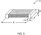
FIG. 3 is a perspective view of a zero-ohm jumper which may be used for an interconnector; -
FIG. 4 is a plan view of the lower laminate sheet after an electrically conductive flowable joining composition is disposed thereon, particularly on the interconnectors; -
FIG. 5 is a plan view of the lower laminate sheet after an elongated metallic conductor is disposed thereon, particularly over the electrically conductive flowable joining composition and interconnectors; -
FIG. 6 is a plan view of a perforated upper laminate sheet for the flexible light engine; -
FIG. 7 is a plan view of the lower and upper laminate sheets after the upper laminate sheet has been disposed over and laminated with the lower laminate sheet, with the first and second bus bars, the interconnectors, the electrically conductive flowable joining composition and the elongated metallic conductor disposed between the lower and upper laminate sheets; -
FIG. 8 is a plan view of the lamination ofFIG. 7 after perforation of the metallic conductor within the upper laminate sheet perforations; and -
FIG. 9 is a plan view of the lamination ofFIG. 8 after addition of light-emitting diodes (LEDs) to form the flexible light engine of according to the present disclosure. - It may be appreciated that the present disclosure is not limited in its application to the details of construction and the arrangement of components set forth in the following description or illustrated in the drawings. The embodiments herein may be capable of being practiced or being carried out in various ways. Also, it may be appreciated that the phraseology and terminology used herein is for the purpose of description and should not be regarded as limiting as such may be understood by one of skill in the art.
- Referring now to
FIGS. 1-9 , and more particularlyFIG. 9 , there is shown aflexible light engine 10 according to the present disclosure. - Turning to
FIGS. 1 and6 ,flexible light engine 10 comprises an elongated, electrically insulating, flexible, lower laminate sheet 12 (FIG. 1 ), as well as an elongated, electrically insulating, flexible, upper laminate sheet 14 (FIG. 6 ). Thelower laminate sheet 12 and theupper laminate sheet 14 may each have a thickness of up to 0.007 inch (0.178 mm). In one exemplary embodiment, thelower laminate sheet 12 and theupper laminate sheet 14 may each be formed of polyethylene terephthalate and may each have a thickness of 0.005 inch (0.127 mm). Thelower laminate sheet 12 and theupper laminate sheet 14 may particularly have the same thickness. - The
lower laminate sheet 12 and theupper laminate sheet 14 may be formed as an elongated strip of plastic, such as a thermoplastic polyester, which may comprise, essentially consist of, or consist of, at least one of polyethylene terephthalate (PET) and polyethylene napthalate (PEN), preferably white. Thelower laminate sheet 12 and theupper laminate sheet 14 may particularly be formed of the same plastic composition. -
Lower laminate sheet 12 andupper laminate sheet 14 are coextensive with respect to major longitudinal direction L and width direction W (which is transverse to the major longitudinal direction L).Lower laminate sheet 12 may be obtained from a first roll of sheet material, whileupper laminate sheet 14 is obtained from a second roll of sheet material, particularly as part of roll-to-roll manufacturing of a circuit for theflexible light engine 10. In contrast tolower laminate sheet 12,upper laminate sheet 14 includes a plurality ofperforations perforations 16 are to be occupied by light-emitting-diode packages 60. However,perforations 18, which are shown to be smaller thanperforations 16 and occur as each eighth perforation, are not so occupied by light-emitting-diode packages 60. - Referring to
FIG. 2 , disposed in a single conductive layer on thelower laminate sheet 12 are a first electrically conductivemetallic bus bar 20 and a second electrically conductivemetallic bus bar 22, which each comprise anelongated strip lower laminate sheet 12. First andsecond bus bars metallic bus bar 20 and the second electrically conductivemetallic bus bar 22 may also be formed in situ by printing or otherwise applying an electrically conductive (organic) ink. It should be understood that a suitable electrically conductive metallic conductor may comprise, essentially consist of, or consist of metal. A preferred conductor of copper, such a copper ribbon, may have a thermal conductivity of about 400 W/m·K as known in the art, through this is not a limiting value. - As also shown in
FIG. 2 , a plurality of (at least two) electricallyconductive interconnectors 30 are arranged at a plurality of spaced locations along the longitudinal direction L of the first andsecond bus bars interconnectors 30 of thefirst bus bar 20 extend in a direction toward thesecond bus bar 22, and similarly theinterconnectors 30 of thesecond bus bar 22 extend in a direction toward thefirst bus bar 20. -
Interconnectors 30 may be formed in-situ by printing or otherwise applying an electrically conductive (organic) ink, which may be understood as an ink which contains electrically conductive particles dispersed in a non-conductive liquid (dryable) carrier. Such inks may comprise silver and/or copper particles. - An exemplary electrically conductive ink may be nanocopper conductive ink from Intrinsiq Materials (Farnborough, UK), which may be used in a High Resolution ElectroStatic Ink JET (ESJET) from Precision Varionic International (Swindon, UK).
- Another exemplary electrically conductive ink may be a single component, solvent-resistant ink from Creative Materials (Ayer, MA), such as product no. 118-09C, which may be understood as silver ink.
- Another exemplary electrically conductive ink may be may be a screen printable, thermoplastic polymer, thick film silver ink from Spraylat Corporation Electronic Materials Group (Mt. Vernon, NY), such as product no. XCSD-006.
- In other embodiments, as shown in
FIG. 3 , theinterconnectors 30 may be formed by surface mounted metallic jumpers, which may be zero-ohm jumpers formed of copper ribbon. For example, the zero-ohm jumper (0.0002 ohm max.) may be a solid copper strip surface mount resistor from Vishay Intertechnology (Malvern, PA). The zero-ohm jumpers may have a length X in a range of 0.060 to 0.250 inch (1.52 to 6.35 mm), a width Y of 0.030 to 0.125 inch (0.76 to 3.18 mm), and a height H of 0.013 to 0.025 inch (0.330 to 0.635 mm) and a thickness T of 0.015 to 0.030 inch (0.381 to 0.762 mm). - In certain embodiments, the foregoing construction of a preformed material for the first and second bus bars 20, 22 being used in conjunction with a material formed in-situ for the
interconnectors 30 may be understood to provide a "hybrid" construction for the electrical pathways which offers certain advantages. For example, the preformed electrically conductive metallic conductor for the first and second bus bars 20, 22 may provide high thermal conductivity and heat dissipation, while the printed electrically conductive metal particle filled liquid solidified in-situ for theinterconnectors 30 may provide low-cost and manufacturing flexibility with regards to formation thereof. - It should be understood that while the
first bus bar 20 andsecond bus bar 22 are shown as being disposed in a single conductive layer on thelower laminate sheet 12, such may be disposed on at least one of thelower laminate sheet 12 and theupper laminate sheet 14. - Referring now to
FIG. 4 , after formation of the first and second bus bars 20, 22, including theinterconnectors 30, abead 36 of an electrically conductive flowable joining composition may be applied at the terminal end of each of theinterconnectors 30. In certain embodiments, thebead 36 of flowable joining composition may be formed of an electrically conductive metal filled epoxy, such as a silver filled epoxy. Alternatively, thebead 36 of electrically conductive flowable joining composition may be formed of electrically conductive metal solder, such as bismuth-tin (Bi-Sn) solder. - Thereafter, as shown in
FIG. 5 , an electrically conductivemetallic strip 40, particularly from a third roll, is disposed in the single conductive layer of each of the first and second bus bars 20, 22, particularly at theinterconnectors 30. As shown, themetallic strip 40 extends parallel with the longitudinal direction L of thelower laminate sheet 12, and with the first and second bus bars 20, 22. Similar to the first and second bus bars 20, 22, themetallic strip 40 may be particularly formed from a pre-formed/pre-shaped metallic conductor, such as at least one of metallic ribbon, metallic tape, and/or metal wire. It should be understood that a suitable electrically conductive metallic conductor may comprise, essentially consist of, or consist of metal. A preferred conductor of copper, such a copper ribbon, may have a thermal conductivity of about 400 W/m·K as known in the art, through this is not a limiting value. - More particularly, the
metallic strip 40 is connected to each of the first and second bus bars 20, 22 via the plurality of spaced locations of theinterconnectors 30 of the first and second bus bars 20, 22, particularly with thebeads 36 of electrically conductive flowable joining composition applied at the terminal end of each of theinterconnectors 30. - Referring now to
FIGS. 6 and 7 , perforatedupper laminate sheet 14 may be disposed over and aligned withlower laminate sheet 12 in the longitudinal direction L, and thereafter laminated withlower laminate sheet 12 such that themetallic strip 40, the first and second bus bars 20, 22 and theinterconnectors 30 are retained between thelower laminate sheet 12 and theupper laminate sheet 14. - If the
beads 36 of flowable joining composition applied at the terminal end of each of theinterconnectors 30 are formed of electrically conductive epoxy, the heat of laminating thelower laminate sheet 12 with theupper laminate sheet 14 may be used to cure the applied electrically conductive epoxy. In such instance, it should be understood that, in applying the electrically conductive epoxy at the terminal end of each of theinterconnectors 30, such is positioned between themetallic strip 40 and one of the first and second bus bars 20, 22. - As shown by
FIG. 7 , theperforations upper laminate sheet 14 are in register withportions 42 of themetallic strip 40, such that themetallic strip portions 42 are exposed. Such may be formed with a "registered lamination" process as known in the art. It should be understood that while the manufacturing process has been described above asupper laminate sheet 14 being perforated withperforations lower laminate sheet 12, theperforations upper laminate sheet 14 may be formed afterupper laminate sheet 14 is laminated withlower laminate sheet 12, such as with a laser. - Thereafter, as shown in
FIG. 8 , the exposedportions 42 of themetallic strip 40 within theperforations upper laminate sheet 14 are also perforated to remove a medial section of the exposedportion 42, thereby defining a plurality of exposed electrically conductive metallic contacts 50 within eachperforation - Furthermore, perforating the exposed
portions 42 of themetallic strip 40 defines a plurality ofmetallic conductors 48, which extend in the longitudinal direction L, with eachmetallic conductor 48 providing two of the metallic contacts 50 at opposing longitudinal ends thereof, particularly with themetallic conductor 48 extending betweenadjacent perforations 16 of theupper laminate sheet 14 in between thelower laminate sheet 12 and theupper laminate sheet 14. - In the foregoing manner and with the foregoing arrangement, as shown by
FIG. 8 , a plurality of electrically conductivemetallic conductors 48, as well as the first and second bus bars 20, 22, are disposed in the single conductive layer between thelower laminate sheet 12 and theupper laminate sheet 14. - It should be understood that, with regards to the plurality of electrically conductive
metallic conductors 48, as well as the first and second bus bars 20, 22, being disposed in the single conductive layer between thelower laminate sheet 12 and theupper laminate sheet 14, that the single layer is preferably devoid of any intervening layer between it and thelower laminate sheet 12, as well as between it and theupper laminate sheet 14. That is, the plurality of electrically conductivemetallic conductors 48, as well as the first and second bus bars 20, 22, are immediately adjacent the lower andupper laminate sheets upper laminate sheets first bus bar 20 is formed onlower laminate sheet 12,second bus bar 22 is formed onupper laminate sheet 14, or both the first and second bus bars 20, 22 are formed on thesame laminate sheet - Continuing with
FIG. 8 , the plurality ofmetallic conductors 48 are disposed laterally, in a width direction W, between thefirst bus bar 20 and thesecond bus bar 22. By being disposed between thelower laminate sheet 12 and theupper laminate sheet 14, themetallic conductors 48 are clamped in position extending betweenadjacent perforations 16 by a compressive force of the lower and upperlaminated sheets - Moreover, as shown, the two metallic contacts 50 of each
metallic conductor 48 are exposed in register withadjacent perforations 16 in the perforatedupper laminate sheet 14. - As shown in
FIG. 9 , in eachperforation 16 of theupper laminate sheet 14, a surface mount light emitting diode (LED)package 60 is coupled to each of the metallic contacts 50 provided by the exposedportions 42 of themetallic conductors 48. After formation of theflexible light engine 10, it may be then coiled onto a fourth roll. - It should be understood that the methods disclosed herein may operate as a continuous, so-called roll-to-roll process, limited in length by the length of the feedstock polymer film for the lower and
upper sheets metallic strip 48, and can typically operate at 300 feet per minute. - With attachment of the LED packages 60, a plurality of parallel LED strings 64 are provided connected in series between the first and second bus bars 20, 22. More particularly, as shown, the
metallic conductors 48 are connected torespective interconnectors 30 to define at least two series circuits 70 (in a single row) and connectable in parallel between the first and second bus bars 20, 22, where each of the at least twoseries circuits 70 comprises a subset of the plurality ofmetallic conductors 48. As such, the plurality ofLEDs 60 attached to themetallic contacts 48 define at least two series LED strings 64 and are connected in parallel between the first and second bus bars 20, 22, with eachLED string 64 comprising a plurality ofLEDs 60. - As set forth above, use of a preformed material (e.g. copper ribbon) for the first and second bus bars 20, 22 being used in conjunction with a material formed in-situ (e.g. printed conductive ink) for the
interconnectors 30 may be understood to provide a "hybrid" construction for the electrical pathways which offers certain advantages. For example, the preformed electrically conductive metallic conductor for the first and second bus bars 20, 22 may provide high thermal conductivity and heat dissipation, while the printed electrically conductive metal particle filled liquid solidified in-situ for theinterconnectors 30 may provide low-cost and manufacturing flexibility with regards to formation thereof. Such may be particularly advantageous for LED tube lamps as explained in greater detail below. - Conventional fluorescent tube lamps may be replaced with LED retrofit tube lamps to eliminate the hazardous waste associated with mercury contained within the fluorescent lamps, as well as reduce power consumption. In doing so, a 48-inch LED retrofit tube lamp (e.g. T8, T10, T12), for example, may utilize a strip of LEDs wired in series in a single row within the lamp.
- By way of example, consider a 2 foot long (61cm) circuit on PET having 24 LEDs connected in series. With use of a
metallic strip 40 of copper ribbon, it may be expected that the voltage drop across the circuit would be about 72 volts (3 volts per LED). Due to the high thermal conductivity and heat dissipation of the copper ribbon metallic strip, the output for the 24 LEDs may be expected to be about 450 lumens, with a junction temperature for each LED of only about 50°C at 50 mA. It is known that maintaining a junction temperature at or below 50°C is important for maintaining lifetime of typical mid-power LEDs. - While use of copper ribbon provides high thermal conductivity and heat dissipation, use of copper ribbon is also relatively expensive. Alternatively, to reduce cost, as well as increase manufacturing flexibility, the
metallic strip 40 may be printed using an electrically conductive ink. However, with such a construction, the junction temperature may be expected to rise to 80°C at 50mA due to the lower thermal conductivity of the printed ink metallic strip as compared to the copper ribbon, which will reduce the lifetime of the LEDs, as well as lower output efficiency to about 420 lumens. - However, by making use of a "hybrid" structure of (1) copper ribbon for the first and second bus bars 20, 22 and the
metallic strip 40; together with (2) printed conductive metallic ink for theinterconnectors 30, particularly in combination with a plurality of parallel LED strings 64 connected in series, a balance of thermal conduction, heat dissipation, manufacturing flexibility, manufacturing cost and lighting performance may be achieved, particularly including maintaining junction temperatures at or below 50°C at 50 mA and providing high lighting efficiency. In part, such may be achieved by forming three strings of eight LEDs in parallel, the voltage is reduced to 24 volts. - While a preferred embodiment of the present disclosure has been described, it should be understood that various changes, adaptations and modifications can be made therein without departing from the spirit of the disclosure and the scope of the appended claims. The scope of the disclosure should, therefore, be determined not with reference to the above description, but instead should be determined with reference to the appended claims along with their full scope of equivalents. Furthermore, it should be understood that the appended claims do not necessarily comprise the broadest scope of the disclosure which the applicant is entitled to claim, or the only manner in which the disclosure may be claimed, or that all recited features are necessary.
-
- 10
- flexible light engine
- 12
- lower laminate sheet
- 14
- upper laminate sheet
- 16
- perforations
- 20
- first bus bar
- 22
- second bus bar
- 24
- first bus bar elongated strip
- 26
- second bus bar elongated strip
- 30
- interconnectors
- 36
- electrically conductive joining composition
- 40
- metallic strip
- 42
- exposed portions of metallic strip
- 48
- metallic conductors
- 50
- metallic contacts
- 60
- LED package
- 64
- LED string
- 70
- series circuits
- 72
- single row
- L
- length direction of flexible light engine
- W
- width direction of flexible light engine
Claims (15)
- A method of roll-to-roll manufacturing a circuit for a flexible light engine (10), comprising:providing an electrically insulating, flexible lower laminate sheet (12) from a first roll;providing an electrically insulating, flexible upper laminate sheet (14) from a second roll;forming electrically conductive first and second metallic bus bars (20, 22) in a single conductive layer on at least one of the lower and upper laminate sheets (12, 14);forming electrically conductive interconnectors (30) at a plurality of locations on each of the first and second metallic bus bars (20, 22);providing a metallic strip (40) from a third roll;disposing the metallic strip (40) in the single conductive layer on at least one of the lower and upper laminate sheets (12, 14);connecting the metallic strip (40) via the interconnectors (30) to the first metallic bus bar (20) at the plurality of interconnector locations of the first metallic bus bar (20);connecting the metallic strip (40) via the interconnectors (30) to the second metallic bus bar (22) at the plurality of electrical interconnector locations of the second metallic bus bar (22);retaining the metallic strip (40) between the lower laminate sheet (12) and the upper laminate sheet (14) by laminating the lower laminate sheet (12) with the upper laminate sheet (14), whereby the laminating also disposes the first and second metallic bus bars (20, 22) between the lower laminate sheet (12) and the upper laminate sheet (14);perforating the upper laminate sheet (14), wherein perforations (16) of the upper laminate sheet (14) are in register with exposed portions (42) of the metallic strip (40);perforating the exposed portions (42) of the metallic strip (40) thereby defining a plurality of metallic contacts (50);coupling an LED package (60) within each perforation (16) of the upper laminate sheet (14) to the metallic contacts (50) provided by the exposed portions (42) of the metallic strip (40), thereby defining a plurality of parallel LED strings (64) connected in series between the first and second metallic bus bars (20, 22); andcoiling the flexible light engine (10) onto a fourth roll.
- The method of claim 1, wherein:perforating the exposed portions (42) of the metallic strip (40) defines a plurality of metallic conductors (48) each having two respective of the metallic contacts (50), each metallic conductor (48) extending between adjacent perforations (16) of the upper laminate sheet (14).
- The method of claim 1 or 2, further comprising:aligning the lower and upper laminate sheets (12, 14) in a major longitudinal direction (L);wherein the first and second metallic bus bars (20, 22) are formed extending in the major longitudinal direction (L); andwherein the metallic strip (40) is disposed extending in the major longitudinal direction (L).
- The method of any one of claims 1 to 3, wherein forming the interconnectors (30) comprises:- printing an electrically conductive ink, or- surface mounting zero-Ohm jumpers.
- The method of any one of claims 1 to 4, further comprising:applying an electrically conductive epoxy (36) between the metallic strip (40) and one of the first and second metallic bus bars (20, 22); andwherein the laminating the lower laminate sheet (12) with the upper laminate sheet (14) cures the applied conductive epoxy (36).
- A flexible light engine (10), comprising:an electrically insulating, flexible lower laminate sheet (12);an electrically insulating, perforated, flexible upper laminate sheet (14);a first metallic bus bar (20) and a second metallic bus bar (22) disposed in a single conductive layer between the lower laminate sheet (12) and the upper laminate sheet (14), the first metallic bus bar (20) and the second metallic bus bar (22) being electrically conductive;a plurality of electrically conductive metallic conductors (48) being disposed in the single conductive layer between the lower laminate sheet (12) and the upper laminate sheet (14) and being disposed laterally, in a width direction (W), between the first metallic bus bar (20) and the second metallic bus bar (22);wherein each metallic conductor (48) defines two metallic contacts (50), the two metallic contacts (50) of each metallic conductor (48) being exposed in register with adjacent perforations (16) in the perforated upper laminate sheet (14);wherein each of the first and second metallic bus bars (20, 22) further comprises respective at least two interconnectors (30), and wherein the metallic conductors (48) are connected to respective interconnectors (30) to define at least two series circuits (70) and connectable in parallel between the first and second metallic bus bars (20, 22), wherein each of the at least two series circuits (70) comprises a subset of the plurality of metallic conductors (48); anda plurality of surface mount light emitting diodes (LEDs) (60) attached to the metallic contacts (48) defining at least two series LED strings (64) and connected in parallel between the first and second metallic bus bars (20, 22), each said LED string (64) comprising a plurality of LEDs (60).
- The flexible light engine (10) of claim 6, wherein:- the lower laminate sheet (12) and the upper laminate sheet (14) comprise at least one of polyethylene terephthalate (PET) and polyethylene napthalate (PEN), or- the lower laminate sheet (12) and the upper laminate sheet (14) consist of at least one of polyethylene terephthalate (PET) and polyethylene napthalate (PEN).
- The flexible light engine (10) of claim 6 or7, wherein:the first and second metallic bus bars (20, 22) comprise at least one of a metallic ribbon, a metallic tape, and/or a metal wire.
- The flexible light engine (10) of any one of claims 6 to 8, wherein:- the interconnectors (30) comprise surface mounted jumpers, or- the interconnectors (30) comprise zero-Ohm jumpers, or- the at least two interconnectors (30) of each of the first and second metallic bus bars (20, 22) are printed from electrically conductive ink containing metal particles.
- The flexible light engine (10) of any one of claims 6 to 9, wherein:the lower laminate sheet (12) and the upper laminate sheet (14) are each formed as a strip extending along a primary major longitudinal direction (L); andwherein the first and second metallic bus bars (20, 22) and the plurality of metallic conductors (48) extend in the longitudinal direction (L).
- The flexible light engine (10) of any one of claims 6 to 10, wherein:the at least two series circuits (70) are disposed in a single row (72).
- The flexible light engine (10) of any one of claims 6 to 11, wherein:the metallic conductors (48) are clamped in position extending between adjacent perforations (16) by a compressive force of the lower and upper laminated sheets (12, 14) without a need for an adhesive.
- The flexible light engine (10) of any one of claims 6 to 12, wherein:the interconnectors (30) of one of the first and second metallic bus bars (20, 22) extend in a direction toward the other of the first and second metallic bus bars (20, 22).
- The flexible light engine (10) of any one of claims 6 to 13, wherein:an electrically conductive flowable joining composition adheres at least one of the metallic conductors (48) to one of the interconnectors (30),wherein, preferably, the electrically conductive flowable joining composition comprises an electrically conductive epoxy or solder.
- The flexible light engine (10) of any one of claims 6 to 14, wherein:the lower laminate sheet (12) and the upper laminate sheet (14) each have a thickness of up to 0.007 inch.
Applications Claiming Priority (1)
| Application Number | Priority Date | Filing Date | Title |
|---|---|---|---|
| US15/244,881 US10132453B2 (en) | 2016-08-23 | 2016-08-23 | Flexible light engine with bus bars and interconnectors |
Publications (2)
| Publication Number | Publication Date |
|---|---|
| EP3288350A1 true EP3288350A1 (en) | 2018-02-28 |
| EP3288350B1 EP3288350B1 (en) | 2022-08-03 |
Family
ID=59350633
Family Applications (1)
| Application Number | Title | Priority Date | Filing Date |
|---|---|---|---|
| EP17179460.5A Active EP3288350B1 (en) | 2016-08-23 | 2017-07-04 | Flexible light engine with bus bars and interconnectors |
Country Status (3)
| Country | Link |
|---|---|
| US (1) | US10132453B2 (en) |
| EP (1) | EP3288350B1 (en) |
| CN (1) | CN107990167B (en) |
Cited By (1)
| Publication number | Priority date | Publication date | Assignee | Title |
|---|---|---|---|---|
| WO2020016076A1 (en) * | 2018-07-18 | 2020-01-23 | Lumileds Holding B.V. | Flexible light-emitting diode lighting strip with interposer |
Families Citing this family (5)
| Publication number | Priority date | Publication date | Assignee | Title |
|---|---|---|---|---|
| TWI693694B (en) * | 2018-04-19 | 2020-05-11 | 曾玠澄 | Process and structure of LED circuit |
| CN108443726A (en) * | 2018-05-21 | 2018-08-24 | 章开明 | A kind of low-voltage LED area array light source module complete using single string and circuit |
| US11359774B2 (en) * | 2018-07-18 | 2022-06-14 | Lumileds Llc | Flexible light-emitting diode lighting strip with interposer |
| US10566513B1 (en) * | 2018-09-17 | 2020-02-18 | Chieh-Chen Tseng | LED circuit structure |
| EP4220210B1 (en) * | 2022-01-28 | 2025-11-05 | Volvo Construction Equipment AB | An apparatus for indicating a status of an electrical cable |
Citations (12)
| Publication number | Priority date | Publication date | Assignee | Title |
|---|---|---|---|---|
| US5151386A (en) | 1990-08-01 | 1992-09-29 | Mobil Solar Energy Corporation | Method of applying metallized contacts to a solar cell |
| US5178685A (en) | 1991-06-11 | 1993-01-12 | Mobil Solar Energy Corporation | Method for forming solar cell contacts and interconnecting solar cells |
| US20080191220A1 (en) | 2004-03-29 | 2008-08-14 | Articulated Technologies, Llc | Roll-to-roll fabricated light sheet and encapsulated semiconductor circuit devices |
| US20080295327A1 (en) | 2007-06-01 | 2008-12-04 | 3M Innovative Properties Company | Flexible circuit |
| US20120241806A1 (en) | 2011-03-25 | 2012-09-27 | Kim Byungmok | Light emitting device package |
| US8314566B2 (en) | 2011-02-22 | 2012-11-20 | Quarkstar Llc | Solid state lamp using light emitting strips |
| CN203656682U (en) * | 2013-11-22 | 2014-06-18 | 鹤山丽得电子实业有限公司 | Bar-shaped lamp with insurance circuit |
| CN203880482U (en) * | 2014-04-29 | 2014-10-15 | 鹤山丽得电子实业有限公司 | LED bar-shaped lamp with insulating liquid solidified thin film layer |
| US20150092413A1 (en) | 2013-09-30 | 2015-04-02 | Osram Sylvania Inc. | Cuttable flexible light engines |
| US20150092429A1 (en) | 2013-09-27 | 2015-04-02 | Osram Sylvania Inc. | Flexible circuit board for electronic applications, light source containing same, and method of making |
| US20150129909A1 (en) | 2013-11-08 | 2015-05-14 | Osram Sylvania Inc. | Flexible circuit board for led lighting fixtures |
| US20150129899A1 (en) | 2013-11-08 | 2015-05-14 | Osram Sylvania Inc. | Led lead frame for laminated led circuits |
Family Cites Families (13)
| Publication number | Priority date | Publication date | Assignee | Title |
|---|---|---|---|---|
| DE4412772A1 (en) | 1994-04-14 | 1995-10-19 | Airsigna Gmbh & Co Kg | Lighting device, in particular emergency lighting device for the interior of watercraft |
| TW558622B (en) | 2002-01-24 | 2003-10-21 | Yuan Lin | Lamp on sheet and manufacturing method thereof |
| US10121950B2 (en) | 2008-03-01 | 2018-11-06 | Goldeneye, Inc. | Lightweight solid state light source with common light emitting and heat dissipating surface |
| CN103053032B (en) | 2010-07-30 | 2016-01-06 | 陶氏环球技术有限责任公司 | For the automatic Composition method of the manufacture of film solar battery module interconnected |
| US8322882B2 (en) | 2010-09-22 | 2012-12-04 | Bridgelux, Inc. | Flexible distributed LED-based light source and method for making the same |
| CN201860505U (en) * | 2010-10-21 | 2011-06-08 | 王定锋 | Combined two-sided PCB |
| DE102010049333B4 (en) | 2010-10-22 | 2012-07-05 | Jürgen Hackert | Method and device for producing a band-shaped structure for receiving electronic components |
| WO2012158709A1 (en) * | 2011-05-16 | 2012-11-22 | The Board Of Trustees Of The University Of Illinois | Thermally managed led arrays assembled by printing |
| CN202563842U (en) * | 2012-04-28 | 2012-11-28 | 深圳市聚智德科技有限公司 | Flexible ultrathin light-emitting diode (LED) display screen |
| US8704448B2 (en) * | 2012-09-06 | 2014-04-22 | Cooledge Lighting Inc. | Wiring boards for array-based electronic devices |
| US8998454B2 (en) * | 2013-03-15 | 2015-04-07 | Sumitomo Electric Printed Circuits, Inc. | Flexible electronic assembly and method of manufacturing the same |
| US20140369033A1 (en) | 2013-06-12 | 2014-12-18 | Paul Palfreyman | Portable lighting systems incorporating deformable light sheets |
| JP5727076B2 (en) * | 2013-06-27 | 2015-06-03 | キヤノン・コンポーネンツ株式会社 | Flexible printed wiring board, flexible circuit board, and electronic device using the same |
-
2016
- 2016-08-23 US US15/244,881 patent/US10132453B2/en active Active
-
2017
- 2017-07-04 EP EP17179460.5A patent/EP3288350B1/en active Active
- 2017-08-22 CN CN201710725843.1A patent/CN107990167B/en active Active
Patent Citations (12)
| Publication number | Priority date | Publication date | Assignee | Title |
|---|---|---|---|---|
| US5151386A (en) | 1990-08-01 | 1992-09-29 | Mobil Solar Energy Corporation | Method of applying metallized contacts to a solar cell |
| US5178685A (en) | 1991-06-11 | 1993-01-12 | Mobil Solar Energy Corporation | Method for forming solar cell contacts and interconnecting solar cells |
| US20080191220A1 (en) | 2004-03-29 | 2008-08-14 | Articulated Technologies, Llc | Roll-to-roll fabricated light sheet and encapsulated semiconductor circuit devices |
| US20080295327A1 (en) | 2007-06-01 | 2008-12-04 | 3M Innovative Properties Company | Flexible circuit |
| US8314566B2 (en) | 2011-02-22 | 2012-11-20 | Quarkstar Llc | Solid state lamp using light emitting strips |
| US20120241806A1 (en) | 2011-03-25 | 2012-09-27 | Kim Byungmok | Light emitting device package |
| US20150092429A1 (en) | 2013-09-27 | 2015-04-02 | Osram Sylvania Inc. | Flexible circuit board for electronic applications, light source containing same, and method of making |
| US20150092413A1 (en) | 2013-09-30 | 2015-04-02 | Osram Sylvania Inc. | Cuttable flexible light engines |
| US20150129909A1 (en) | 2013-11-08 | 2015-05-14 | Osram Sylvania Inc. | Flexible circuit board for led lighting fixtures |
| US20150129899A1 (en) | 2013-11-08 | 2015-05-14 | Osram Sylvania Inc. | Led lead frame for laminated led circuits |
| CN203656682U (en) * | 2013-11-22 | 2014-06-18 | 鹤山丽得电子实业有限公司 | Bar-shaped lamp with insurance circuit |
| CN203880482U (en) * | 2014-04-29 | 2014-10-15 | 鹤山丽得电子实业有限公司 | LED bar-shaped lamp with insulating liquid solidified thin film layer |
Cited By (2)
| Publication number | Priority date | Publication date | Assignee | Title |
|---|---|---|---|---|
| WO2020016076A1 (en) * | 2018-07-18 | 2020-01-23 | Lumileds Holding B.V. | Flexible light-emitting diode lighting strip with interposer |
| US11121122B2 (en) | 2018-07-18 | 2021-09-14 | Lumileds Llc | Flexible light-emitting diode lighting strip with interposer |
Also Published As
| Publication number | Publication date |
|---|---|
| CN107990167B (en) | 2021-04-23 |
| CN107990167A (en) | 2018-05-04 |
| EP3288350B1 (en) | 2022-08-03 |
| US20180058649A1 (en) | 2018-03-01 |
| US10132453B2 (en) | 2018-11-20 |
Similar Documents
| Publication | Publication Date | Title |
|---|---|---|
| EP3288350B1 (en) | Flexible light engine with bus bars and interconnectors | |
| US10134714B2 (en) | Flexible circuit board for LED lighting fixtures | |
| US9859483B2 (en) | Flip-chip light emitting diode and method for manufacturing the same | |
| US20160252231A1 (en) | Light emitting device | |
| JP5760122B2 (en) | Flexible wiring board for light emitting device mounting, light emitting device | |
| CN108878628B (en) | Semiconductor light engine for a tube lamp | |
| US8779694B1 (en) | LEDs on flexible substrate arrangement | |
| US20080123334A1 (en) | LED light engine with applied foil construction | |
| JP2019067903A (en) | Light emitting device and method of manufacturing the same | |
| EP3427555A1 (en) | A lighting device and corresponding method | |
| JP2017501592A (en) | Light emitting film structure | |
| WO2019098029A1 (en) | Electronic device and manufacturing method thereof | |
| US10257935B2 (en) | Method for manufacturing a printed circuit board assembly based on printed electronics | |
| JP7003478B2 (en) | Electronic device and its manufacturing method | |
| WO2016104616A1 (en) | Led-mounted module and led display device | |
| JP2016122819A (en) | Substrate for LED element and LED display device | |
| CN102170748B (en) | Adhesive flexible circuit board, its manufacturing method and strip light with the circuit board | |
| KR20140086020A (en) | Flexible substrate for illumination and fabricating method thereof | |
| JP2015015374A (en) | Printed circuit board, electronic circuit and printed circuit board manufacturing method | |
| CN210351772U (en) | LED lamp area circuit board | |
| KR20140114091A (en) | Led chips array module and method of manufacturing the same | |
| TW201128949A (en) | Laminated flexible circuit board, a manufacturing method | |
| JP6501180B2 (en) | Light emitting device and flexible wiring board | |
| JP2016115802A (en) | Flexible wiring board, flexible circuit board, and manufacturing method of flexible wiring board | |
| CN102934529A (en) | Flexible printed wiring board |
Legal Events
| Date | Code | Title | Description |
|---|---|---|---|
| PUAI | Public reference made under article 153(3) epc to a published international application that has entered the european phase |
Free format text: ORIGINAL CODE: 0009012 |
|
| STAA | Information on the status of an ep patent application or granted ep patent |
Free format text: STATUS: THE APPLICATION HAS BEEN PUBLISHED |
|
| AK | Designated contracting states |
Kind code of ref document: A1 Designated state(s): AL AT BE BG CH CY CZ DE DK EE ES FI FR GB GR HR HU IE IS IT LI LT LU LV MC MK MT NL NO PL PT RO RS SE SI SK SM TR |
|
| AX | Request for extension of the european patent |
Extension state: BA ME |
|
| STAA | Information on the status of an ep patent application or granted ep patent |
Free format text: STATUS: REQUEST FOR EXAMINATION WAS MADE |
|
| 17P | Request for examination filed |
Effective date: 20180810 |
|
| RBV | Designated contracting states (corrected) |
Designated state(s): AL AT BE BG CH CY CZ DE DK EE ES FI FR GB GR HR HU IE IS IT LI LT LU LV MC MK MT NL NO PL PT RO RS SE SI SK SM TR |
|
| STAA | Information on the status of an ep patent application or granted ep patent |
Free format text: STATUS: EXAMINATION IS IN PROGRESS |
|
| 17Q | First examination report despatched |
Effective date: 20210309 |
|
| GRAP | Despatch of communication of intention to grant a patent |
Free format text: ORIGINAL CODE: EPIDOSNIGR1 |
|
| STAA | Information on the status of an ep patent application or granted ep patent |
Free format text: STATUS: GRANT OF PATENT IS INTENDED |
|
| RIC1 | Information provided on ipc code assigned before grant |
Ipc: F21K 9/27 20160101ALN20210930BHEP Ipc: H05K 1/02 20060101ALN20210930BHEP Ipc: H05K 3/20 20060101ALI20210930BHEP Ipc: H05K 1/18 20060101AFI20210930BHEP |
|
| RIC1 | Information provided on ipc code assigned before grant |
Ipc: F21K 9/27 20160101ALN20211005BHEP Ipc: H05K 1/02 20060101ALN20211005BHEP Ipc: H05K 3/20 20060101ALI20211005BHEP Ipc: H05K 1/18 20060101AFI20211005BHEP |
|
| INTG | Intention to grant announced |
Effective date: 20211022 |
|
| RIC1 | Information provided on ipc code assigned before grant |
Ipc: F21K 9/27 20160101ALN20211008BHEP Ipc: H05K 1/02 20060101ALN20211008BHEP Ipc: H05K 3/20 20060101ALI20211008BHEP Ipc: H05K 1/18 20060101AFI20211008BHEP |
|
| GRAJ | Information related to disapproval of communication of intention to grant by the applicant or resumption of examination proceedings by the epo deleted |
Free format text: ORIGINAL CODE: EPIDOSDIGR1 |
|
| STAA | Information on the status of an ep patent application or granted ep patent |
Free format text: STATUS: EXAMINATION IS IN PROGRESS |
|
| GRAP | Despatch of communication of intention to grant a patent |
Free format text: ORIGINAL CODE: EPIDOSNIGR1 |
|
| INTC | Intention to grant announced (deleted) | ||
| STAA | Information on the status of an ep patent application or granted ep patent |
Free format text: STATUS: GRANT OF PATENT IS INTENDED |
|
| RIC1 | Information provided on ipc code assigned before grant |
Ipc: F21K 9/27 20160101ALN20220321BHEP Ipc: H05K 1/02 20060101ALN20220321BHEP Ipc: H05K 3/20 20060101ALI20220321BHEP Ipc: H05K 1/18 20060101AFI20220321BHEP |
|
| INTG | Intention to grant announced |
Effective date: 20220407 |
|
| GRAS | Grant fee paid |
Free format text: ORIGINAL CODE: EPIDOSNIGR3 |
|
| GRAA | (expected) grant |
Free format text: ORIGINAL CODE: 0009210 |
|
| STAA | Information on the status of an ep patent application or granted ep patent |
Free format text: STATUS: THE PATENT HAS BEEN GRANTED |
|
| AK | Designated contracting states |
Kind code of ref document: B1 Designated state(s): AL AT BE BG CH CY CZ DE DK EE ES FI FR GB GR HR HU IE IS IT LI LT LU LV MC MK MT NL NO PL PT RO RS SE SI SK SM TR |
|
| REG | Reference to a national code |
Ref country code: AT Ref legal event code: REF Ref document number: 1509801 Country of ref document: AT Kind code of ref document: T Effective date: 20220815 Ref country code: CH Ref legal event code: EP |
|
| REG | Reference to a national code |
Ref country code: DE Ref legal event code: R096 Ref document number: 602017060102 Country of ref document: DE |
|
| REG | Reference to a national code |
Ref country code: IE Ref legal event code: FG4D |
|
| REG | Reference to a national code |
Ref country code: LT Ref legal event code: MG9D |
|
| REG | Reference to a national code |
Ref country code: NL Ref legal event code: MP Effective date: 20220803 |
|
| PG25 | Lapsed in a contracting state [announced via postgrant information from national office to epo] |
Ref country code: SE Free format text: LAPSE BECAUSE OF FAILURE TO SUBMIT A TRANSLATION OF THE DESCRIPTION OR TO PAY THE FEE WITHIN THE PRESCRIBED TIME-LIMIT Effective date: 20220803 Ref country code: RS Free format text: LAPSE BECAUSE OF FAILURE TO SUBMIT A TRANSLATION OF THE DESCRIPTION OR TO PAY THE FEE WITHIN THE PRESCRIBED TIME-LIMIT Effective date: 20220803 Ref country code: PT Free format text: LAPSE BECAUSE OF FAILURE TO SUBMIT A TRANSLATION OF THE DESCRIPTION OR TO PAY THE FEE WITHIN THE PRESCRIBED TIME-LIMIT Effective date: 20221205 Ref country code: NO Free format text: LAPSE BECAUSE OF FAILURE TO SUBMIT A TRANSLATION OF THE DESCRIPTION OR TO PAY THE FEE WITHIN THE PRESCRIBED TIME-LIMIT Effective date: 20221103 Ref country code: NL Free format text: LAPSE BECAUSE OF FAILURE TO SUBMIT A TRANSLATION OF THE DESCRIPTION OR TO PAY THE FEE WITHIN THE PRESCRIBED TIME-LIMIT Effective date: 20220803 Ref country code: LV Free format text: LAPSE BECAUSE OF FAILURE TO SUBMIT A TRANSLATION OF THE DESCRIPTION OR TO PAY THE FEE WITHIN THE PRESCRIBED TIME-LIMIT Effective date: 20220803 Ref country code: LT Free format text: LAPSE BECAUSE OF FAILURE TO SUBMIT A TRANSLATION OF THE DESCRIPTION OR TO PAY THE FEE WITHIN THE PRESCRIBED TIME-LIMIT Effective date: 20220803 Ref country code: FI Free format text: LAPSE BECAUSE OF FAILURE TO SUBMIT A TRANSLATION OF THE DESCRIPTION OR TO PAY THE FEE WITHIN THE PRESCRIBED TIME-LIMIT Effective date: 20220803 Ref country code: ES Free format text: LAPSE BECAUSE OF FAILURE TO SUBMIT A TRANSLATION OF THE DESCRIPTION OR TO PAY THE FEE WITHIN THE PRESCRIBED TIME-LIMIT Effective date: 20220803 |
|
| REG | Reference to a national code |
Ref country code: AT Ref legal event code: MK05 Ref document number: 1509801 Country of ref document: AT Kind code of ref document: T Effective date: 20220803 |
|
| PG25 | Lapsed in a contracting state [announced via postgrant information from national office to epo] |
Ref country code: PL Free format text: LAPSE BECAUSE OF FAILURE TO SUBMIT A TRANSLATION OF THE DESCRIPTION OR TO PAY THE FEE WITHIN THE PRESCRIBED TIME-LIMIT Effective date: 20220803 Ref country code: IS Free format text: LAPSE BECAUSE OF FAILURE TO SUBMIT A TRANSLATION OF THE DESCRIPTION OR TO PAY THE FEE WITHIN THE PRESCRIBED TIME-LIMIT Effective date: 20221203 Ref country code: HR Free format text: LAPSE BECAUSE OF FAILURE TO SUBMIT A TRANSLATION OF THE DESCRIPTION OR TO PAY THE FEE WITHIN THE PRESCRIBED TIME-LIMIT Effective date: 20220803 Ref country code: GR Free format text: LAPSE BECAUSE OF FAILURE TO SUBMIT A TRANSLATION OF THE DESCRIPTION OR TO PAY THE FEE WITHIN THE PRESCRIBED TIME-LIMIT Effective date: 20221104 |
|
| PG25 | Lapsed in a contracting state [announced via postgrant information from national office to epo] |
Ref country code: SM Free format text: LAPSE BECAUSE OF FAILURE TO SUBMIT A TRANSLATION OF THE DESCRIPTION OR TO PAY THE FEE WITHIN THE PRESCRIBED TIME-LIMIT Effective date: 20220803 Ref country code: RO Free format text: LAPSE BECAUSE OF FAILURE TO SUBMIT A TRANSLATION OF THE DESCRIPTION OR TO PAY THE FEE WITHIN THE PRESCRIBED TIME-LIMIT Effective date: 20220803 Ref country code: DK Free format text: LAPSE BECAUSE OF FAILURE TO SUBMIT A TRANSLATION OF THE DESCRIPTION OR TO PAY THE FEE WITHIN THE PRESCRIBED TIME-LIMIT Effective date: 20220803 Ref country code: CZ Free format text: LAPSE BECAUSE OF FAILURE TO SUBMIT A TRANSLATION OF THE DESCRIPTION OR TO PAY THE FEE WITHIN THE PRESCRIBED TIME-LIMIT Effective date: 20220803 Ref country code: AT Free format text: LAPSE BECAUSE OF FAILURE TO SUBMIT A TRANSLATION OF THE DESCRIPTION OR TO PAY THE FEE WITHIN THE PRESCRIBED TIME-LIMIT Effective date: 20220803 |
|
| REG | Reference to a national code |
Ref country code: DE Ref legal event code: R097 Ref document number: 602017060102 Country of ref document: DE |
|
| PG25 | Lapsed in a contracting state [announced via postgrant information from national office to epo] |
Ref country code: SK Free format text: LAPSE BECAUSE OF FAILURE TO SUBMIT A TRANSLATION OF THE DESCRIPTION OR TO PAY THE FEE WITHIN THE PRESCRIBED TIME-LIMIT Effective date: 20220803 Ref country code: EE Free format text: LAPSE BECAUSE OF FAILURE TO SUBMIT A TRANSLATION OF THE DESCRIPTION OR TO PAY THE FEE WITHIN THE PRESCRIBED TIME-LIMIT Effective date: 20220803 |
|
| PLBE | No opposition filed within time limit |
Free format text: ORIGINAL CODE: 0009261 |
|
| STAA | Information on the status of an ep patent application or granted ep patent |
Free format text: STATUS: NO OPPOSITION FILED WITHIN TIME LIMIT |
|
| PG25 | Lapsed in a contracting state [announced via postgrant information from national office to epo] |
Ref country code: AL Free format text: LAPSE BECAUSE OF FAILURE TO SUBMIT A TRANSLATION OF THE DESCRIPTION OR TO PAY THE FEE WITHIN THE PRESCRIBED TIME-LIMIT Effective date: 20220803 |
|
| 26N | No opposition filed |
Effective date: 20230504 |
|
| PG25 | Lapsed in a contracting state [announced via postgrant information from national office to epo] |
Ref country code: SI Free format text: LAPSE BECAUSE OF FAILURE TO SUBMIT A TRANSLATION OF THE DESCRIPTION OR TO PAY THE FEE WITHIN THE PRESCRIBED TIME-LIMIT Effective date: 20220803 |
|
| REG | Reference to a national code |
Ref country code: DE Ref legal event code: R119 Ref document number: 602017060102 Country of ref document: DE |
|
| PG25 | Lapsed in a contracting state [announced via postgrant information from national office to epo] |
Ref country code: MC Free format text: LAPSE BECAUSE OF FAILURE TO SUBMIT A TRANSLATION OF THE DESCRIPTION OR TO PAY THE FEE WITHIN THE PRESCRIBED TIME-LIMIT Effective date: 20220803 |
|
| PG25 | Lapsed in a contracting state [announced via postgrant information from national office to epo] |
Ref country code: MC Free format text: LAPSE BECAUSE OF FAILURE TO SUBMIT A TRANSLATION OF THE DESCRIPTION OR TO PAY THE FEE WITHIN THE PRESCRIBED TIME-LIMIT Effective date: 20220803 |
|
| REG | Reference to a national code |
Ref country code: CH Ref legal event code: PL |
|
| REG | Reference to a national code |
Ref country code: BE Ref legal event code: MM Effective date: 20230731 |
|
| PG25 | Lapsed in a contracting state [announced via postgrant information from national office to epo] |
Ref country code: LU Free format text: LAPSE BECAUSE OF NON-PAYMENT OF DUE FEES Effective date: 20230704 |
|
| GBPC | Gb: european patent ceased through non-payment of renewal fee |
Effective date: 20230704 |
|
| PG25 | Lapsed in a contracting state [announced via postgrant information from national office to epo] |
Ref country code: LU Free format text: LAPSE BECAUSE OF NON-PAYMENT OF DUE FEES Effective date: 20230704 |
|
| REG | Reference to a national code |
Ref country code: IE Ref legal event code: MM4A |
|
| PG25 | Lapsed in a contracting state [announced via postgrant information from national office to epo] |
Ref country code: DE Free format text: LAPSE BECAUSE OF NON-PAYMENT OF DUE FEES Effective date: 20240201 Ref country code: CH Free format text: LAPSE BECAUSE OF NON-PAYMENT OF DUE FEES Effective date: 20230731 Ref country code: GB Free format text: LAPSE BECAUSE OF NON-PAYMENT OF DUE FEES Effective date: 20230704 |
|
| PG25 | Lapsed in a contracting state [announced via postgrant information from national office to epo] |
Ref country code: IT Free format text: LAPSE BECAUSE OF FAILURE TO SUBMIT A TRANSLATION OF THE DESCRIPTION OR TO PAY THE FEE WITHIN THE PRESCRIBED TIME-LIMIT Effective date: 20220803 Ref country code: FR Free format text: LAPSE BECAUSE OF NON-PAYMENT OF DUE FEES Effective date: 20230731 Ref country code: BE Free format text: LAPSE BECAUSE OF NON-PAYMENT OF DUE FEES Effective date: 20230731 |
|
| PG25 | Lapsed in a contracting state [announced via postgrant information from national office to epo] |
Ref country code: IE Free format text: LAPSE BECAUSE OF NON-PAYMENT OF DUE FEES Effective date: 20230704 |
|
| PG25 | Lapsed in a contracting state [announced via postgrant information from national office to epo] |
Ref country code: IE Free format text: LAPSE BECAUSE OF NON-PAYMENT OF DUE FEES Effective date: 20230704 |
|
| PG25 | Lapsed in a contracting state [announced via postgrant information from national office to epo] |
Ref country code: BG Free format text: LAPSE BECAUSE OF FAILURE TO SUBMIT A TRANSLATION OF THE DESCRIPTION OR TO PAY THE FEE WITHIN THE PRESCRIBED TIME-LIMIT Effective date: 20220803 |
|
| PG25 | Lapsed in a contracting state [announced via postgrant information from national office to epo] |
Ref country code: BG Free format text: LAPSE BECAUSE OF FAILURE TO SUBMIT A TRANSLATION OF THE DESCRIPTION OR TO PAY THE FEE WITHIN THE PRESCRIBED TIME-LIMIT Effective date: 20220803 |
|
| PG25 | Lapsed in a contracting state [announced via postgrant information from national office to epo] |
Ref country code: CY Free format text: LAPSE BECAUSE OF FAILURE TO SUBMIT A TRANSLATION OF THE DESCRIPTION OR TO PAY THE FEE WITHIN THE PRESCRIBED TIME-LIMIT; INVALID AB INITIO Effective date: 20170704 |
|
| PG25 | Lapsed in a contracting state [announced via postgrant information from national office to epo] |
Ref country code: HU Free format text: LAPSE BECAUSE OF FAILURE TO SUBMIT A TRANSLATION OF THE DESCRIPTION OR TO PAY THE FEE WITHIN THE PRESCRIBED TIME-LIMIT; INVALID AB INITIO Effective date: 20170704 |
|
| PG25 | Lapsed in a contracting state [announced via postgrant information from national office to epo] |
Ref country code: TR Free format text: LAPSE BECAUSE OF FAILURE TO SUBMIT A TRANSLATION OF THE DESCRIPTION OR TO PAY THE FEE WITHIN THE PRESCRIBED TIME-LIMIT Effective date: 20220803 |