EP3288218B1 - Verfahren zur übertragung eines statusberichts einer pdcp-schicht in einem mobiltelekommunikationssystem und empfänger für mobiltelekommunikation - Google Patents
Verfahren zur übertragung eines statusberichts einer pdcp-schicht in einem mobiltelekommunikationssystem und empfänger für mobiltelekommunikation Download PDFInfo
- Publication number
- EP3288218B1 EP3288218B1 EP17193618.0A EP17193618A EP3288218B1 EP 3288218 B1 EP3288218 B1 EP 3288218B1 EP 17193618 A EP17193618 A EP 17193618A EP 3288218 B1 EP3288218 B1 EP 3288218B1
- Authority
- EP
- European Patent Office
- Prior art keywords
- pdcp
- layer
- sdus
- status report
- bitmap
- Prior art date
- Legal status (The legal status is an assumption and is not a legal conclusion. Google has not performed a legal analysis and makes no representation as to the accuracy of the status listed.)
- Active
Links
- 238000000034 method Methods 0.000 title claims description 36
- 238000012545 processing Methods 0.000 claims description 12
- 238000010295 mobile communication Methods 0.000 claims description 4
- 230000006870 function Effects 0.000 description 17
- 230000006835 compression Effects 0.000 description 15
- 238000007906 compression Methods 0.000 description 15
- 230000005540 biological transmission Effects 0.000 description 14
- 238000004891 communication Methods 0.000 description 8
- 230000006837 decompression Effects 0.000 description 8
- 230000008569 process Effects 0.000 description 7
- IESVDEZGAHUQJU-ZLBXKVHBSA-N 1-hexadecanoyl-2-(4Z,7Z,10Z,13Z,16Z,19Z-docosahexaenoyl)-sn-glycero-3-phosphocholine Chemical compound CCCCCCCCCCCCCCCC(=O)OC[C@H](COP([O-])(=O)OCC[N+](C)(C)C)OC(=O)CC\C=C/C\C=C/C\C=C/C\C=C/C\C=C/C\C=C/CC IESVDEZGAHUQJU-ZLBXKVHBSA-N 0.000 description 4
- 230000014509 gene expression Effects 0.000 description 4
- 230000007774 longterm Effects 0.000 description 4
- 238000012986 modification Methods 0.000 description 4
- 230000004048 modification Effects 0.000 description 4
- 238000010586 diagram Methods 0.000 description 3
- 230000000694 effects Effects 0.000 description 2
- VJYFKVYYMZPMAB-UHFFFAOYSA-N ethoprophos Chemical compound CCCSP(=O)(OCC)SCCC VJYFKVYYMZPMAB-UHFFFAOYSA-N 0.000 description 2
- 238000013467 fragmentation Methods 0.000 description 2
- 238000006062 fragmentation reaction Methods 0.000 description 2
- 238000013507 mapping Methods 0.000 description 2
- 230000007246 mechanism Effects 0.000 description 2
- 238000012546 transfer Methods 0.000 description 2
- 241000760358 Enodes Species 0.000 description 1
- 230000003139 buffering effect Effects 0.000 description 1
- 230000002708 enhancing effect Effects 0.000 description 1
- 230000008520 organization Effects 0.000 description 1
- 230000011218 segmentation Effects 0.000 description 1
- 230000011664 signaling Effects 0.000 description 1
- 239000002699 waste material Substances 0.000 description 1
Images


Classifications
-
- H—ELECTRICITY
- H04—ELECTRIC COMMUNICATION TECHNIQUE
- H04W—WIRELESS COMMUNICATION NETWORKS
- H04W24/00—Supervisory, monitoring or testing arrangements
- H04W24/02—Arrangements for optimising operational condition
-
- H—ELECTRICITY
- H04—ELECTRIC COMMUNICATION TECHNIQUE
- H04L—TRANSMISSION OF DIGITAL INFORMATION, e.g. TELEGRAPHIC COMMUNICATION
- H04L1/00—Arrangements for detecting or preventing errors in the information received
- H04L1/12—Arrangements for detecting or preventing errors in the information received by using return channel
- H04L1/16—Arrangements for detecting or preventing errors in the information received by using return channel in which the return channel carries supervisory signals, e.g. repetition request signals
- H04L1/1607—Details of the supervisory signal
- H04L1/1614—Details of the supervisory signal using bitmaps
-
- H—ELECTRICITY
- H04—ELECTRIC COMMUNICATION TECHNIQUE
- H04L—TRANSMISSION OF DIGITAL INFORMATION, e.g. TELEGRAPHIC COMMUNICATION
- H04L1/00—Arrangements for detecting or preventing errors in the information received
- H04L1/12—Arrangements for detecting or preventing errors in the information received by using return channel
- H04L1/16—Arrangements for detecting or preventing errors in the information received by using return channel in which the return channel carries supervisory signals, e.g. repetition request signals
- H04L1/1607—Details of the supervisory signal
- H04L1/1685—Details of the supervisory signal the supervisory signal being transmitted in response to a specific request, e.g. to a polling signal
-
- H—ELECTRICITY
- H04—ELECTRIC COMMUNICATION TECHNIQUE
- H04W—WIRELESS COMMUNICATION NETWORKS
- H04W24/00—Supervisory, monitoring or testing arrangements
-
- H—ELECTRICITY
- H04—ELECTRIC COMMUNICATION TECHNIQUE
- H04W—WIRELESS COMMUNICATION NETWORKS
- H04W80/00—Wireless network protocols or protocol adaptations to wireless operation
- H04W80/02—Data link layer protocols
-
- H—ELECTRICITY
- H04—ELECTRIC COMMUNICATION TECHNIQUE
- H04L—TRANSMISSION OF DIGITAL INFORMATION, e.g. TELEGRAPHIC COMMUNICATION
- H04L1/00—Arrangements for detecting or preventing errors in the information received
- H04L1/12—Arrangements for detecting or preventing errors in the information received by using return channel
- H04L1/16—Arrangements for detecting or preventing errors in the information received by using return channel in which the return channel carries supervisory signals, e.g. repetition request signals
- H04L1/1607—Details of the supervisory signal
- H04L1/1671—Details of the supervisory signal the supervisory signal being transmitted together with control information
-
- H—ELECTRICITY
- H04—ELECTRIC COMMUNICATION TECHNIQUE
- H04L—TRANSMISSION OF DIGITAL INFORMATION, e.g. TELEGRAPHIC COMMUNICATION
- H04L69/00—Network arrangements, protocols or services independent of the application payload and not provided for in the other groups of this subclass
- H04L69/30—Definitions, standards or architectural aspects of layered protocol stacks
- H04L69/32—Architecture of open systems interconnection [OSI] 7-layer type protocol stacks, e.g. the interfaces between the data link level and the physical level
- H04L69/321—Interlayer communication protocols or service data unit [SDU] definitions; Interfaces between layers
-
- H—ELECTRICITY
- H04—ELECTRIC COMMUNICATION TECHNIQUE
- H04L—TRANSMISSION OF DIGITAL INFORMATION, e.g. TELEGRAPHIC COMMUNICATION
- H04L69/00—Network arrangements, protocols or services independent of the application payload and not provided for in the other groups of this subclass
- H04L69/30—Definitions, standards or architectural aspects of layered protocol stacks
- H04L69/32—Architecture of open systems interconnection [OSI] 7-layer type protocol stacks, e.g. the interfaces between the data link level and the physical level
- H04L69/322—Intralayer communication protocols among peer entities or protocol data unit [PDU] definitions
-
- H—ELECTRICITY
- H04—ELECTRIC COMMUNICATION TECHNIQUE
- H04W—WIRELESS COMMUNICATION NETWORKS
- H04W28/00—Network traffic management; Network resource management
- H04W28/02—Traffic management, e.g. flow control or congestion control
- H04W28/06—Optimizing the usage of the radio link, e.g. header compression, information sizing, discarding information
Definitions
- the present invention relates to a method for transmitting a PDCP status report for reporting to another party a reception status of a PDCP SDU in a PDCP layer in Long Term Evolution (LTE) system.
- LTE Long Term Evolution
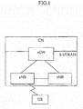
- FIG 1 shows an exemplary network structure of a Long Term Evolution (LTE) system as a related art mobile communication system.
- LTE Long Term Evolution
- the LTE system is a system that has evolved from the existing UMTS system, and its standardization work is currently being performed by the 3GPP standards organization.
- the LTE network can roughly be divided into an Evolved UMTS Terrestrial Radio Access Network (E-UTRAN) and a Core Network (CN).
- the E-UTRAN generally comprises a terminal (i.e., User Equipment (UE)), a base station (i.e., eNode B), an Access Gateway (aGW) that is located at an end of the network and connects with one or more external networks.
- the aGW may be divided into a portion for handling user traffic and a portion for processing control traffic.
- the access gateway part that processes the user traffic and the access gateway part that processes the control traffic may communicate with a new interface.
- One or more cells may exist in a single eNB.
- An interface may be used for transmitting user traffic or control traffic between eNBs.
- the CN may include the access gateway and a node or the like for user registration of the UE.
- An interface for discriminating the E-UTRAN and the CN may be used.
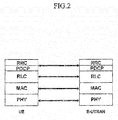
- Figure 2 shows an exemplary control plane architecture of a radio interface protocol between a terminal and an E-UTRAN according to the 3GPP radio access network standard.
- Figure 3 shows an exemplary user plane architecture of a radio interface protocol between a terminal and an E-UTRAN according to the 3GPP radio access network standard.
- the radio interface protocol is horizontally comprised of a physical layer, a data link layer, and a network layer, and vertically comprised of a user plane for transmitting user data and a control plane for transferring control signaling.
- the protocol layer as shown in Figs. 2 and 3 may be divided into L1 (Layer 1), L2 (Layer 2), and L3 (Layer 3) based upon the lower three layers of the Open System Interconnection (OSI) standards model that is widely known in the field of communication systems.
- OSI Open System Interconnection
- the physical layer uses a physical channel to provide an information transfer service to a higher layer.
- the physical layer is connected with a medium access control (MAC) layer located thereabove via a transport channel, and data is transferred between the physical layer and the MAC layer via the transport channel.
- the transport channel is divided into a dedicated transport channel and a common channel according to whether or not a channel is shared. Also, between respectively different physical layers, namely, between the respective physical layers of the transmitting side (transmitter) and the receiving side (receiver), data is transmitted via a physical channel.
- the second layer includes various layers.
- a medium access control (MAC) layer performs mapping various logical channels to various transport channels and performs logical channel multiplexing by mapping several logical channels to a single transport channel.
- the MAC layer is connected to an upper layer called a radio link control (RLC) layer by a logical channel.
- RLC radio link control
- the logical channel is divided into a control channel that transmits information of the control plane and a traffic channel that transmits information of the user plane according to a type of transmitted information.
- An RLC (Radio Resource Control) layer of the second layer segments and/or concatenates data received from an upper layer to adjust the data size so as for a lower layer to suitably transmit the data to a radio interface.
- the RLC layer provides three operational modes: a TM (Transparent Mode); a UM (Unacknowledged Mode); and an AM (Acknowledged Mode).
- the RLC layer operating in the AM referred to as an 'AM RLC layer', hereinafter) performs a retransmission function through an automatic repeat and request (ARQ) function for a reliable data transmission.
- a packet data convergence protocol (PDCP) layer of the second layer performs a function called header compression that reduces the size of a header of an IP packet, which is relatively large and includes unnecessary control information, in order to effectively transmit the IP packet such as an IPv4 or IPv6 in a radio interface having a narrow bandwidth.
- the header compression increases transmission efficiency between radio interfaces by allowing the header part of the data to transmit only the essential information.
- the RRC layer located at the lowermost portion of the third layer is defined only in the control plane, and controls a logical channel, a transport channel and a physical channel in relation to configuration, reconfiguration, and the release of radio bearers (RBs).
- the RBs refer to a logical path provided by the first and second layers of the radio protocol for data transmission between the UE and the UTRAN.
- configuration (or setup) of the RB refers to the process of stipulating the characteristics of a radio protocol layer and a channel required for providing a particular data service, and setting the respective detailed parameters and operational methods.
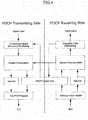
- Figure 4 shows an exemplary structure of a PDCP entity.
- description of the PDCP entity will be given in detail. It should be noted that blocks as shown in Fig. 4 are functional blocks, therefore there may have a difference when actually implementing such blocks.
- the PDCP entity is upwardly connected to the RRC layer or a user application, and downwardly to the RLC layer. Detailed structure thereof is described as below.
- One PDCP entity as shown in Fig. 4 is comprised of a transmitting side and a receiving side.
- the transmitting side at the left may configure an SDU received from an upper layer as a PDU or configure control information generated by the PDCP entity itself as a PDU, and transmit the same to a peer PDCP entity as a receiving side.
- the receiving side at the right, the peer PDCP entity abstracts PDCP SDU or control information from the PDCP PDU received from the transmitting side.
- the PDU generated by the transmitting side of the PDCP entity may have two types of a Data PDU and a Control PDU.
- the PDCP Data PDU is a data block formed by processing the SDU received from the upper layer by the PDCP entity
- the PDCP Control PDU is a data block generated by the PDCP entity itself to deliver control information to the peer entity.
- the PDCP Data PDU is generated in RBs of the user plane (U-plane) and the control plane (C-plane), and some functions of the PDCP entity are selectively applied according to the type of a used plane. That is, the header compression function is applied only to U-plane data, and an integrity protection function among the security functions is applied only to C-plane data. In addition to the integrity protection function, a ciphering function for data security may also be included in the security functions. Here, the ciphering function is applied to both the U-plane data and the C-plane data.
- the PDCP Control PDU is generated in a U-plane RB only, and may be roughly divided into two types: a 'PDCP status report' for notifying a PDCP entity receiving buffer status to the transmitting side; and a 'Header Compression (HC) feedback packet' for notifying a status of a receiving side header decompressor to a transmitting side header compressor.
- a 'PDCP status report' for notifying a PDCP entity receiving buffer status to the transmitting side
- HC 'Header Compression
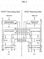
- Figure 5 is a block diagram illustrating processing steps of each PDCP PDU in a PDCP entity.
- Fig. 5 shows processing steps of the three types of PDCP PDUs (i. e., the PDCP Data PDU, the PDCP control PDU for PDCP status report, and the PDCP Control PDU for header compression feedback) in the PDCP entity through paths 1 to 8.
- PDCP PDUs i. e., the PDCP Data PDU, the PDCP control PDU for PDCP status report, and the PDCP Control PDU for header compression feedback
- WO 2006/118418 A2 relates to a method of transmitting control information in a wireless communication system and a transmission window updating method using the same, by which transmission efficiency in a transmitting side can be enhanced. It includes the steps of receiving a first control information block including a first status report information from a receiving side, the first status information providing reception acknowledge information for a plurality of data blocks transmitted to the receiving side, receiving a second control information block including a second status report information placed as a last status report information in the second control information block, and updating the transmission window using the reception acknowledge information in the first status report information.
- EP 1626518 A2 relates to a bitmap structure which enables the size of a bitmap field containing reception result information to be significantly reduced while fully performing its acknowledgment function.
- a message region for recording indicators which enables reception success or failure for the maximum allowable SN level packets treatable by block ACK to be confirmed, is assigned.
- a message region for recording only the reception results for unsuccessfully received packets is also assigned.
- a receiving party confirms the unsuccessfully received packets through the indicators, and retransmits the unsuccessfully received packets.
- a transmitting party provides the number of SN level packets and the maximum number of fragmentation packets to the receiving party. The receiving party determines an optimized bitmap configuration scheme, and transmits the reception results for the respective fragmentation packets to the transmitting party based on the determined bitmap configuration scheme.
- WO 2007/078142 A1 relates to a method which can reduce loss in data transmission.
- a data block is prepared in a high-level layer and the data block is transmitted in a low-level layer.
- Status report information associated with reception or non-reception of the data block is received through the low-level layer.
- the transmitter can rapidly recognize the reception failure and can retransmit the data.
- WO 01/78286 A2 relates to a method and a telecommunication system for data packet numbering in packet-switched data transmission in connection with a handover, in which the responsibility for a connection is transferred from the connection between a mobile station and a first wireless telecommunication network to the connection between said mobile station and a second wireless telecommunication network.
- a data packet number space available for data packet numbering is bigger than a data packet number space of the second wireless telecommunication network.
- Data packet numbering is restricted in the first wireless telecommunication network such that the numbers of the data packets of the first wireless telecommunication network do not exceed the maximum value of the data packet number space of the second wireless telecommunication network.
- the receiving side PDCP entity may use the PDCP status report to request the retransmission of the PDCP SDU having not been received from the transmitting side PDCP entity.
- the PDCP entity should generate a PDCP Control PDU in an appropriate form and transmit the same to another party.
- the type of the format to be used for transmission has not been decided yet.
- the present invention is to define a format of a PDCP Control PDU which the receiving side PDCP entity uses to transmit the PDCP status report to the transmitting side PDCP entity as a peer entity.
- the present invention is to provide a method of informing, by the PDCP entity, a receiving buffer status in the form of a bitmap.
- a method for transmitting a status report of a PDCP layer in a mobile telecommunications system in which a method for transmitting, by a receiving side PDCP layer, a status report about a series of data to a transmitting side PDCP layer, the method comprising: determining, by the receiving side PDCP layer, a reception status of the series of data, wherein the series of data is PDCP SDUs; and transmitting, by the receiving side PDCP layer, a reception status report for the PDCP SDUs to the transmitting side PDCP layer, wherein the reception status report is transmitted in the form of a bitmap including sequence number information of the PDCP SDUs indicating whether or not the PDCP SDUs have successfully been received.
- the reception status report for the PDCP SDUs is transmitted from the receiving side PDCP layer to the transmitting side PDCP layer in the form of a PDCP Control PDU.
- the PDCP Control PDU includes a bitmap field.
- the PDCP Control PDU includes a Last Sequence Number (LSN) field or a First Sequence Number (FSN) field.
- LSN Last Sequence Number
- FSN First Sequence Number
- the LSN field indicates a sequence number (SN) of a PDCP SDU corresponding to the last bit of the bitmap field.
- the FSN field indicates a sequence number (SN) of a PDCP SDU corresponding to the first bit of the bitmap field.
- the PDCP Control PDU includes a Length field, and the Length field includes information indicating a length of the bitmap.
- the bitmap field is configured as indicators indicating whether or not each of the PDCP SDUs has successfully been received.
- each of the indicators is comprised of one bit, and a value of the one bit is set to '0' or '1' so as to indicate whether or not a corresponding PDCP SDU has successfully been received.
- a receiver in a mobile telecommunications system comprising: a communication module which determines whether or not PDCP SDUs received through a PDCP layer have successfully been received; generates information regarding the reception success or failure of the determined PDCP SDUs in the form of a bitmap; and includes the information generated in the form of the bitmap in the PDCP Control PDU for transmission.
- the PDCP Control PDU Includes a Last Sequence Number (LSN) field or a First Sequence Number (FSN) field, wherein the LSN field indicates a Sequence Number (SN) of a PDCP SDU corresponding to the last bit of the bitmap field, and the FSN field indicates a Sequence Number (SN) of a PDCP SDU corresponding to the first bit of the bitmap field.
- LSN Last Sequence Number
- FSN First Sequence Number
- the PDCP Control PDU includes a Length field, wherein the Length field includes information indicating a length of the bitmap.
- the present invention has an effect of, when transmitting a PDCP status report so as to re-transmit a PDCP SDU having not been received in the PDCP layer, reducing a size of a header by effectively generating a status report as well as preventing the waste of radio resources.
- the present invention is applied to the Long Term Evolution (LTE) system of a mobile telecommunications system, and more particularly, to an Evolved Universal Mobile Telecommunications System (E-UMTS) that has evolved from UMTS.
- LTE Long Term Evolution
- E-UMTS Evolved Universal Mobile Telecommunications System
- the present invention may be also applied to any mobile telecommunications system and communication protocol to which technical features of the present invention is applicable.
- a first component may be referred to as a second component, or similarly, the second component may be referred to as the first component, without departing from the scope of the present invention.
- a term 'and/or' is used to include a combination of a plurality of disclosed items or one of the items.
- the present invention has recognized that there is no appropriate format of a PDCP Control PDU when the receiving side PDCP entity uses the PDCP status report to request the retransmission of the PDCP SDU having not been received from the transmitting side PDCP entity as a peer entity.
- the present invention conceptually relates to 1) notify, by the PDCP entity, a status of a receiving buffer in the form of a bitmap, and 2) define a format of a PDCP Control PDU in the form of the bitmap to notify to the transmitting side PDCP entity as a peer entity. 3) That is, the receiving side PDCP entity expresses the reception status of each PDCP SDU in 1 bit such that reception success is set to 1 and reception failure is set to 0. 4) In particular, the presence of the reception success is not determined by whether or not the PDCP PDU has successfully been received, but by whether or not the PDCP SDU has been received. That is, if the PDCP SDU obtained by performing deciphering and header decompression on the received PDCP PDU does not have any error, it is determined to be the reception success.
- the Sequence Number (SN) of the PDCP PDU and the Sequence Number (SN) of the PDCP SDU are distinguished from each other.
- Fig. 6 the difference between the PDCP PDU and the PDCP SDU, and the difference between the SN of the PDCP PDU and the SN of the PDCP SDU will be described.
- the contents in Fig. 6 has cited from the contents related to Fig. 5 in the specification of KR 20080085694 A (filed on Mar. 06, 2008) ( US 2010091709 A1 filed on Mar. 19, 2007)" applied by the applicant of this invention. Meanwhile, other portions in the above application may also be cited for explanation of the present invention.
- Figure 6 shows L2 protocol architecture and a sequential order in processing data by a transmitting side.
- Figure 6 shows the sequential order in processing and transmitting data which has been received by the transmitting side of the RLC and PDCP layers in an LTE from an upper layer.
- the sequential order is as follows.
- an SDU refers to data received from an upper layer and PDU refers to data transmitted to a lower layer after being received from an upper layer and processed.
- the PDCP layer receives data (PDCP SDUs) to be transmitted to a lower layer, from an upper layer.
- the PDCP layer sets a virtual SN (Sequence Number) with respect to each PDCP SDU.
- the PDCP SDU SNs are sequentially set to discriminate the respective PDCP SDUs.
- the step S11 is performed by a first setting module.
- the SNs are not actually added to the PDCP SDUs but the respective PDCP SDUs are managed by sort of pointers (not shown) which are discriminated by each different SN. For this reason, the SNs in step S11 are expressed as virtual SNs. Furthermore, this reason makes implicit expression in step S11 in Fig. 6 wherein each SN (i.e., virtual SN) of the PDCP SDUs is drawn by dotted lines.
- the PDCP layer stores the respective PDCP SDUs in a PDCP SDU buffer. This is for a source base station (i.e., source NodeB) to forward a PDCP SDU whose reception has been unconfirmed by a terminal (UE) to target base station by the source NodeB to the target NodeB during handover.
- source NodeB i.e., source NodeB
- UE terminal
- the PDCP SDUs When the PDCP SDUs are forwarded or re-transmitted during handover, only the PDCP SDUs that have not been properly received by the receiving side according to a status report of the RLC layer or the PDCP layer are forwarded or re-transmitted. This is called a selective forwarding/retransmission.
- the step 12 is performed by the PDCP SDU buffer.
- the 2-times virtual SN setting processes and the 3-times PDCP SDU buffering may be simultaneously performed. If the PDCP layer does not support the selective forwarding/retransmission, the PDCP SDU buffer may not be provided.
- a header compressor (or header compression module) sequentially performs header compression on the PDCP SDUs.
- the header compressor may generate a header compression feedback packet or a PDCP STATUS PDU, etc., which are unrelated to the PDCP SDUs, by itself.
- the PDCP layer sequentially ciphers the header-compressed PDCP SDUs.
- the PDCP layer performs ciphering by using virtual PDCP SNs which were set when the PDCP SDUs were stored in the buffer.
- the PDCP SNs act as input parameters in a ciphering algorithm to serve to generate each different ciphering mask for each SDU.
- the step S14 is performed by the ciphering module.
- the PDCP layer may perform a security function including an integrity protection function. Also, in case of the integrity protection, the PDCP SDUs are integrity-protected by using virtual PDCP SNs.
- the PDCP layer may include packets generated by the PDCP layer itself, such as a feedback packet generated by the header compressor itself and the PDCP STATUS PDU, etc., generated by the PDCP layer itself.
- the feedback packet or the PDCP STATUS PDU, etc. are not ciphered because they do not have any corresponding PDCP SDUs or any set virtual PDCP SNs.
- the virtual PDCP SNs i.e., the SNs set in step S11
- the virtual PDCP SNs set in step S11 are attached to the PDCP PDU headers to form PDCP PDUs.
- the virtual PDCP SNs set in step S11 are explicitly attached to the respective SDUs as PDCP SNs.
- the step S15 is performed by a second setting module.
- the feedback packet or the PDCP STATUS PDU, etc. configure a PDCP PDU by itself without the PDCP SN.
- the PDCP layer transfers the thusly configured PDCP PDUs to the lower RLC layer.
- the RLC layer Upon receiving the RLC SDUs, namely, the PDCP PDUs, from the PDCP layer, the RLC layer stores them in the RLC SDU buffer. This is to flexibly support the PDU size of the RLC layer.
- the RLC layer stores the RLC SDUs in the SDU buffer, and when a lower MAC layer requests transmission of them at every transmission time, the RLC layer segments and/or concatenates the RLC SDUs as many as required according to the requested size.
- the step S17 is performed by a segmentation and concatenation module.
- the RLC layer sequentially attaches RLC SNs to the segmented and/or concatenated data blocks.
- the RLC layer may generate an RLC control PDU by itself irrespective of the RLD SDUs.
- the RLC SN-attached data blocks or the RLC SN-free RLC control PDU constitute RLC PDUs.
- the step S18 is performed by a third setting module.
- the AMC RLC layer stores the constructed RLC PDUs in an RLC PDU buffer. This is for a re-transmission that may be necessary afterwards.
- the PDCP SNs in steps S11 and S15 and the RLC SN in step S18 have different properties as described above. Namely, the PDCP SNs are used for ciphering in the PDCP layer and eventually used for forwarding or re-transmitting only the PDCP data whose reception has not been confirmed by the receiving side. Meanwhile, the RLC SNs are used at the RLC layer and have a different purpose from that of the PDCP SNs.
- the PDCP SNs are attached to the SDUs, and when the PDCP SN-attached SDUs are transferred to the RLC layer, the RLC SNs are additionally attached thereto.
- the present invention defines the format of the PDCP Control PDU which the receiving side PDCP entity uses to transmit the PDCP status report to the transmitting side PDCP entity as a peer entity. For this, the present invention proposes a method for notifying, by the PDPC entity, a status of a receiving buffer in the form of a bitmap.
- bitmap is comprised of one or more bits.
- Each bit of the bitmap includes information about a reception status report, i.e., whether or not the PDCP SDUs have successfully been received.
- the receiving side PDCP entity expresses the reception status of each PDCP SDU in 1 bit such that reception success is set to "1" and reception failure is set to "0."
- the presence of the reception success is not determined by whether or not the PDCP PDU has successfully been received, but by whether or not the PDCP SDU has been received, i.e., if the PDCP SDU obtained by performing deciphering and header decompression on the received PDCP PDU does not have any error. That is, each bit of the bitmap of the PDCP status report acts as an indicator informing the presence of a successful reception of a single PDCP SDU.
- Bits adjacent to each other based on a certain bit (this indicates the presence of the reception success of the PDCP SDU having the certain SN) in the bitmap include information regarding whether or not the PDCP SDUs having adjacent sequence numbers have been successfully received. Accordingly, all bitmaps serve as status reports indicating the reception status (i.e., reception success or reception failure) of all PDCP SDUs having sequence numbers within a certain range.
- SN information of the PDCP SDU indicated by the first or the last bit of the bitmap should be included in the PDCP Control PDU.
- Such SN information of the PDCP SDU may be the SN of a PDCP SDU corresponding to the first bit of the bitmap ('FSN 'in Fig. 8 ) or the SN of a PDCP SDU corresponding to the last bit ('LSN' in Fig. 7 ).
- the Length field indicating the length is also needed.
- Figure 7 shows an exemplary format of a PDCP Control PDU for a PDCP status report according to a first embodiment of the present invention.
- Fig. 7 shows an embodiment including the 'LSN' field.
- the format of the PDCP Control PDU in Fig. 7 may include a LENGTH field, a LSN field and a BITMAP field, in addition to the D/C field and the Control PDU type field.
- the LENGTH field is an optional field, and may or may not be included in the PDCP Control PDU.
- the LENGTH field is added into the PDCP Control PDU when the length of the bitmap should be notified.
- the LENGTH field is not required.
- the bitmap field includes reception status information of each PDCP SDU indicating whether or not the PDCP SDUs received from the transmitting side PDCP and processed by the receiving side PDCP entity have been successfully received without any error.
- the SN of the first or last PDCP SDU of the bitmap should be added to accurately notify the sequence numbers of respective PDCP SDUs corresponding to each bitmap.
- the SN of the last PDCP SDU i.e., Last Sequence Number (LSN)
- LSN Last Sequence Number
- Fig. 7 shows the format of the PDCP Control PDU when the length of the bitmap should be notified.
- Each bit_position in the bitmap is 1 ⁇ LENGTH*8, for instance, if the LENGTH is '5,' each bit_position would be '1' ⁇ '40.' That is, the number of bits in the bitmap is 40. In other words, the number of PDCP SDUs which are the targets of the reception status reports (reception success or failure) of corresponding PDCP SDUs is 40.
- An interpretation method of each bit_position is as follows:
- the LENGTH is '0,' the Bitmap field does not exist. In this case, the LSN only is included, considering that all PDCP SDUs have been successfully received.
- Figure 8 shows an exemplary format of a PDCP Control PDU for a PDCP status report according to a second embodiment of the present invention.
- Fig. 8 shows an embodiment including the 'FSN' field.
- the embodiment in Fig. 8 will describe a difference from that given in Fig. 7 .
- the embodiment in Fig. 8 uses the First Sequence Number (FSN), instead of the LSN, to notify an accurate sequence number of a PDCP SDU.
- FSN corresponds to an SN of a target PDCP SDU indicated by the first bit of a bitmap. That is, the first bit of the bitmap has information about the reception status of the PDCP SDU indicated by the FSN.
- the LENGTH field is not required.
- the method of setting the FSN and bitmap by using the FSN, instead of the LSN, has a little difference from that described in Fig. 7 .
- a value of the FSN field indicates an SN of a PDCP SDU corresponding to the first bit of the bitmap field.
- the value of the FSN field corresponds to the SN of a PDCP SDU which has not been firstly received, by the receiving side PDCP entity, among the PDCP SDUs received from the transmitting side PDCP entity.
- a range of the BITMAP indicates PDCP SDUs whose SNs are between [FSN, FSN + LENGTH*8 -1], and includes information about the reception success or failure.
- target PDCP SDUs are those of which SNs are between 'FSN' and 'FSN + LENGTH*8 -1.
- Each bit of the bitmaps has reception status information (i.e., PDCP Status Report) regarding whether or not the PDCP SDUs indicated by each bit have been successfully received. For instance, if a FSN value is '100' and a LENGTH value is '5,' a range of SN of the PDCP SDU as the target of the reception status report would be '100' - '139.'
- Each bit_position in the bitmap is 1 ⁇ LENGTH*8, and for instance, if a LENGTH is '5,' the bit_position would be '1' ⁇ '40.' That is, the number of the bits in the bitmap is 40. In other words, the number of PDCP SDUs which are the targets of the reception status reports (reception success or failure) of corresponding PDCP SDUs is 40.
- Figs. 7 and 8 have described the format of the PDCP Control PDU of the reception status information (i . e ., the PDCP status report) for a series of data (i.e., PDCP SDUs) in which the receiving side PDCP entity receives from the transmitting side PDCP entity as a peer entity.
- the method for transmitting the PDCP Control PDU of the reception status information (i.e., PDCP status report) for a series of data (i.e., PDCP SDUs) will be summarized as follows.
- the receiving side PDCP entity obtains the PDCP SDUs by performing ciphering and header decompression on the PDCP PDUs received from the transmitting side PDCP entity, and then checks whether or not each of the PDCP SDUs has an error and thereby to determine the reception success or failure of each of the PDCP SDUs.
- the receiving side PDCP entity adds each indicator (each bit of the bitmap) indicating the reception status (i.e., reception success or failure) of each PDCP SDU into the BITMAP field.
- the receiving side PDCP entity configures the PDCP Control PDU including the BITMAP field and transmits the configured PDCP Control PDU to the transmitting side PDCP entity.
- the PDCP Control PDU may include the LENGTH field indicating the size of the BITMAP field.
- the PDCP Control PDU may include LSN field or FSN field.
- the LSN field has SN information of the PDCP SDU corresponding to the last bit of the BITMAP field.
- the FSN field has SN information of the PDCP SDU corresponding to the first bit (uppermost bit) of the BITMAP field.
- the present invention uses the LSN and FSN fields, thereby not requiring to have SNs of a corresponding PDCP SDUs for all bit_positions of the BITMAP field, thus to reduce the size of the PDCP Control PDU as well as enhancing efficiency of resources.
- the receiver (receiving apparatus) includes hardware, software, a module having software, and the like that can implement the embodiments of Figs. 7 and 8 .
- the apparatus according to the present invention may be called an entity, and the apparatus according to the present invention may be a terminal.
- the receiver according to the present invention may include a communication module capable of performing functions described in Figs. 7 and 8 .
- the communication module which determines the reception success or failure for each of in-sequence PDCP SDUs received through the PDCP layer, generates a status report for the determined result in the form of a bitmap, and transmits a PDCP Control PDU including the status report generated in the form of the bitmap.
- the PDCP Control PDU includes the LSN field or FSN field.
- the LSN field indicates a sequence number (SN) of a PDCP SDU corresponding to the last bit of the bitmap field
- the FSN field indicates a sequence number (SN) of a PDCP SDU corresponding to the first bit of the bitmap field.
- the transmitter (transmitting apparatus) includes a communication module capable of performing functions described in Figs. 7 and 8 .
- functions of such communication module have already been described in Figs. 7 and 8 , therefore detailed explanations therefor are omitted.
- the receiver and transmitter according to the present invention basically include software, hardware required for implementing the technical idea of the present invention, in addition to the above-described elements, such as an output unit (display, speaker, or the like), an input unit (keypad, microphone, and the like), a memory, a microprocessor, a transmission/reception unit (RF module, antenna, and the like).
- an output unit display, speaker, or the like
- an input unit keyboard, microphone, and the like
- a memory a microprocessor
- RF module radio frequency
- the method described so far may be implemented by software, hardware or their combination thereof.
- the method according to the present invention may be implemented by codes or command languages in a software program that can be stored in a storage medium (e.g., an internal memory of a mobile terminal, a flash memory, a hard disk, or the like), and that can be executed by a processor (e.g., an internal microprocessor of a mobile terminal).
- a storage medium e.g., an internal memory of a mobile terminal, a flash memory, a hard disk, or the like
- a processor e.g., an internal microprocessor of a mobile terminal.
Claims (12)
- Verfahren zur Übertragung eines Statusberichts in einer Paketdatenkonvergenzprotokoll-, PDCP-, Schicht eines Mobilkommunikationssystems, etwa in einem LTE- oder E-UMTS-System, wobei das Verfahren ausgeführt wird von einer empfangsseitigen PDCP-Schicht, wobei das Verfahren die Schritte umfasst:Erzeugen, durch die empfangsseitige PDCP-Schicht, des Statusberichts für eine oder mehrere PDCP-Dienstdateneinheiten, SDUs, die von einer sendeseitigen PDCP-Schicht gesendet wurden, wobei der Statusbericht angibt, ob die gesendeten PDCP-SDUs auf der Empfangsseite empfangen worden sind oder nicht, wobei der Statusbericht in einer Form eines Bitkartenfeldes in einer PDCP-Protokolldateneinheit, PDU, erzeugt wird, undwobei ein spezielles Bit in dem Bitkartenfeld angibt, ob eine entsprechende der PDCP-SDUs empfangen worden ist, undSenden, durch die empfangsseitige PDCP-Schicht, des Statusberichts an die sendeseitige PDCP-Schicht.
- Verfahren nach Anspruch 1, wobei das spezielle Bit in dem Bitkartenfeld mit einem einzigen Bit konfiguriert wird.
- Verfahren nach Anspruch 2, wobei das einzige Bit auf "0" oder "1" gesetzt wird, um anzugeben, ob die entsprechende PDCP-SDU empfangen worden ist.
- Verfahren nach Anspruch 3, wobei das einzige Bit auf "0" gesetzt wird, wenn die entsprechende der PDCP-SDUs auf der Empfangsseite fehlt.
- Verfahren nach Anspruch 3, wobei das einzige Bit auf "1" gesetzt wird, wenn die entsprechende der PDCP-SDUs nicht erneut gesendet werden muss.
- Verfahren nach Anspruch 1, wobei eine Länge des Bitkartenfeldes variabel ist und "0" sein kann.
- Empfänger zum Empfangen einer empfangsseitigen PDCP-Schicht, wobei der Empfänger aufweist:eine Verarbeitungsschaltung, die ausgebildet ist, einen Statusbericht in einer Paketdatenkonvergenzprotokoll-, PDCP-, Schicht eines Mobilkommunikationssystems, etwa eines LTE- oder eines E-UMTS-Systems, für eine oder mehrere PDCP-Dienstdateneinheiten, SDUs, zu erzeugen, die aus einer sendeseitigen PDCP-Schicht gesendet wurden,wobei der Statusbericht angibt, ob die gesendeten PDCP-SDUs im Empfänger empfangen worden sind,wobei der Statusbericht in Form eines Bitkartenfeldes erzeugt wird, undwobei ein spezielles Bit in dem Bitkartenfeld angibt, ob eine entsprechende der PDCP-SDUs empfangen worden ist, undeinen Sender, der ausgebildet ist, den Statusbericht an die Sendeseite zu senden.
- Empfänger nach Anspruch 7, wobei das spezielle Bit in dem Bitkartenfeld mit einem einzigen Bit konfiguriert ist.
- Empfänger nach Anspruch 8, wobei die Verarbeitungsschaltung ausgebildet ist, das einzige Bit auf "0" oder "1" zu setzen, um anzugeben, ob die entsprechende der PDCP-SDUs empfangen worden ist.
- Empfänger nach Anspruch 9, wobei die Verarbeitungsschaltung ausgebildet ist, das einzige Bit auf "0" zu setzen, wenn die entsprechende der PDCP-SDUs auf der Empfangsseite fehlt.
- Empfänger nach Anspruch 9, wobei die Verarbeitungsschaltung ausgebildet ist, das einzige Bit auf "1" zu setzen, wenn die entsprechende der PDCP-SDUs nicht erneut gesendet werden muss.
- Empfänger nach Anspruch 7, wobei eine Länge der Bitkarte variabel ist und "0" sein kann.
Priority Applications (4)
| Application Number | Priority Date | Filing Date | Title |
|---|---|---|---|
| PL17193618T PL3288218T3 (pl) | 2007-09-11 | 2008-09-10 | Sposób transmitowania raportu o stanie w warstwie PDCP w systemie telekomunikacji ruchomej i odbiornik telekomunikacji ruchomej |
| EP19172464.0A EP3541021B1 (de) | 2007-09-11 | 2008-09-10 | Verfahren zur übertragung eines statusberichts einer pdcp-schicht in einem mobiltelekommunikationssystem und empfänger für mobiltelekommunikation |
| PL19172464T PL3541021T3 (pl) | 2007-09-11 | 2008-09-10 | Sposób transmitowania raportu o stanie w warstwie PDCP w systemie telekomunikacji mobilnej i odbiornik telekomunikacji mobilnej |
| EP20213842.6A EP3809637B1 (de) | 2007-09-11 | 2008-09-10 | Verfahren zur übertragung eines statusberichts einer pdcp-schicht in einem mobiltelekommunikationssystem und empfänger für mobiltelekommunikation |
Applications Claiming Priority (4)
| Application Number | Priority Date | Filing Date | Title |
|---|---|---|---|
| US97148007P | 2007-09-11 | 2007-09-11 | |
| KR1020080088970A KR100907978B1 (ko) | 2007-09-11 | 2008-09-09 | 이동통신 시스템에서 pdcp 계층의 상태보고 전송 방법 및 수신장치 |
| EP08793753.8A EP2188952B1 (de) | 2007-09-11 | 2008-09-10 | Verfahren für einen sendestatusbericht einer pdcp-schicht in einem mobilen telekommunikationssystem und empfänger für mobile telekommunikation |
| PCT/KR2008/005345 WO2009035262A1 (en) | 2007-09-11 | 2008-09-10 | Method for transmitting status report of pdcp layer in mobile telecommunications system and receiver of mobile telecommunications |
Related Parent Applications (2)
| Application Number | Title | Priority Date | Filing Date |
|---|---|---|---|
| EP08793753.8A Division EP2188952B1 (de) | 2007-09-11 | 2008-09-10 | Verfahren für einen sendestatusbericht einer pdcp-schicht in einem mobilen telekommunikationssystem und empfänger für mobile telekommunikation |
| EP08793753.8A Division-Into EP2188952B1 (de) | 2007-09-11 | 2008-09-10 | Verfahren für einen sendestatusbericht einer pdcp-schicht in einem mobilen telekommunikationssystem und empfänger für mobile telekommunikation |
Related Child Applications (2)
| Application Number | Title | Priority Date | Filing Date |
|---|---|---|---|
| EP19172464.0A Division EP3541021B1 (de) | 2007-09-11 | 2008-09-10 | Verfahren zur übertragung eines statusberichts einer pdcp-schicht in einem mobiltelekommunikationssystem und empfänger für mobiltelekommunikation |
| EP20213842.6A Division EP3809637B1 (de) | 2007-09-11 | 2008-09-10 | Verfahren zur übertragung eines statusberichts einer pdcp-schicht in einem mobiltelekommunikationssystem und empfänger für mobiltelekommunikation |
Publications (2)
| Publication Number | Publication Date |
|---|---|
| EP3288218A1 EP3288218A1 (de) | 2018-02-28 |
| EP3288218B1 true EP3288218B1 (de) | 2019-05-15 |
Family
ID=42320379
Family Applications (4)
| Application Number | Title | Priority Date | Filing Date |
|---|---|---|---|
| EP17193618.0A Active EP3288218B1 (de) | 2007-09-11 | 2008-09-10 | Verfahren zur übertragung eines statusberichts einer pdcp-schicht in einem mobiltelekommunikationssystem und empfänger für mobiltelekommunikation |
| EP08793753.8A Active EP2188952B1 (de) | 2007-09-11 | 2008-09-10 | Verfahren für einen sendestatusbericht einer pdcp-schicht in einem mobilen telekommunikationssystem und empfänger für mobile telekommunikation |
| EP19172464.0A Active EP3541021B1 (de) | 2007-09-11 | 2008-09-10 | Verfahren zur übertragung eines statusberichts einer pdcp-schicht in einem mobiltelekommunikationssystem und empfänger für mobiltelekommunikation |
| EP20213842.6A Active EP3809637B1 (de) | 2007-09-11 | 2008-09-10 | Verfahren zur übertragung eines statusberichts einer pdcp-schicht in einem mobiltelekommunikationssystem und empfänger für mobiltelekommunikation |
Family Applications After (3)
| Application Number | Title | Priority Date | Filing Date |
|---|---|---|---|
| EP08793753.8A Active EP2188952B1 (de) | 2007-09-11 | 2008-09-10 | Verfahren für einen sendestatusbericht einer pdcp-schicht in einem mobilen telekommunikationssystem und empfänger für mobile telekommunikation |
| EP19172464.0A Active EP3541021B1 (de) | 2007-09-11 | 2008-09-10 | Verfahren zur übertragung eines statusberichts einer pdcp-schicht in einem mobiltelekommunikationssystem und empfänger für mobiltelekommunikation |
| EP20213842.6A Active EP3809637B1 (de) | 2007-09-11 | 2008-09-10 | Verfahren zur übertragung eines statusberichts einer pdcp-schicht in einem mobiltelekommunikationssystem und empfänger für mobiltelekommunikation |
Country Status (10)
| Country | Link |
|---|---|
| US (8) | US7936723B2 (de) |
| EP (4) | EP3288218B1 (de) |
| JP (1) | JP5279732B2 (de) |
| KR (1) | KR100907978B1 (de) |
| CN (2) | CN101766003B (de) |
| ES (3) | ES2653539T3 (de) |
| HU (1) | HUE054182T2 (de) |
| NO (1) | NO2188952T3 (de) |
| PL (3) | PL3541021T3 (de) |
| WO (1) | WO2009035262A1 (de) |
Families Citing this family (60)
| Publication number | Priority date | Publication date | Assignee | Title |
|---|---|---|---|---|
| US8818375B2 (en) * | 2007-04-25 | 2014-08-26 | Telefonaktiebolaget L M Ericsson (Publ) | Method and apparatus for seamless handover in a wireless communication network |
| KR101486352B1 (ko) | 2007-06-18 | 2015-01-26 | 엘지전자 주식회사 | 무선 통신 시스템의 단말에서의 상향링크 동기 상태 제어방법 |
| KR101341515B1 (ko) | 2007-06-18 | 2013-12-16 | 엘지전자 주식회사 | 무선 통신 시스템에서의 반복 전송 정보 갱신 방법 |
| WO2008156314A2 (en) | 2007-06-20 | 2008-12-24 | Lg Electronics Inc. | Effective system information reception method |
| US8594030B2 (en) | 2007-08-10 | 2013-11-26 | Lg Electronics Inc. | Method for controlling HARQ operation in dynamic radio resource allocation |
| KR101514841B1 (ko) | 2007-08-10 | 2015-04-23 | 엘지전자 주식회사 | 효율적인 랜덤 액세스 재시도를 수행하는 방법 |
| KR101490253B1 (ko) | 2007-08-10 | 2015-02-05 | 엘지전자 주식회사 | 무선 통신 시스템에서의 제어정보 전송 및 수신 방법 |
| KR101461965B1 (ko) | 2007-08-14 | 2014-11-14 | 엘지전자 주식회사 | 무선 통신 시스템의 특정 프로토콜 계층에서의 데이터 블록전송 및 처리 방법 |
| KR100907978B1 (ko) | 2007-09-11 | 2009-07-15 | 엘지전자 주식회사 | 이동통신 시스템에서 pdcp 계층의 상태보고 전송 방법 및 수신장치 |
| KR101461970B1 (ko) | 2007-09-13 | 2014-11-14 | 엘지전자 주식회사 | 무선 통신 시스템에서의 폴링 과정 수행 방법 |
| KR100937432B1 (ko) | 2007-09-13 | 2010-01-18 | 엘지전자 주식회사 | 무선 통신 시스템에서의 무선자원 할당 방법 |
| KR101435844B1 (ko) | 2007-09-18 | 2014-08-29 | 엘지전자 주식회사 | 무선 통신 시스템에서의 데이터 블록 전송 방법 |
| KR101591824B1 (ko) | 2007-09-18 | 2016-02-04 | 엘지전자 주식회사 | 무선 통신 시스템에서의 폴링 과정 수행 방법 |
| KR101396062B1 (ko) | 2007-09-18 | 2014-05-26 | 엘지전자 주식회사 | 헤더 지시자를 이용한 효율적인 데이터 블록 전송방법 |
| KR101513033B1 (ko) | 2007-09-18 | 2015-04-17 | 엘지전자 주식회사 | 다중 계층 구조에서 QoS를 보장하기 위한 방법 |
| US8687565B2 (en) | 2007-09-20 | 2014-04-01 | Lg Electronics Inc. | Method of effectively transmitting radio resource allocation request in mobile communication system |
| TWI470982B (zh) * | 2007-09-28 | 2015-01-21 | Interdigital Patent Holdings | 分組數據匯聚協議中控制協議數據單元方法及裝置 |
| KR101487557B1 (ko) | 2007-10-23 | 2015-01-29 | 엘지전자 주식회사 | 공통제어채널의 데이터를 전송하는 방법 |
| KR20090041323A (ko) | 2007-10-23 | 2009-04-28 | 엘지전자 주식회사 | 데이터 블록 구성함에 있어서 단말의 식별 정보를 효과적으로 전송하는 방법 |
| KR20090043465A (ko) | 2007-10-29 | 2009-05-06 | 엘지전자 주식회사 | 무선 베어러 타입에 따른 오류 해결 방법 |
| ES2362173T3 (es) * | 2008-02-04 | 2011-06-29 | Lg Electronics Inc. | Método de comunicación inalámbrica para transmitir una secuencia de unidades de datos entre un dispositivo inalámbrico y una red. |
| EP2266224B1 (de) | 2008-03-17 | 2017-06-14 | LG Electronics Inc. | Verfahren zum übertragen von rlc-daten |
| KR101163275B1 (ko) | 2008-03-17 | 2012-07-05 | 엘지전자 주식회사 | Pdcp 상태 보고 전송 방법 |
| ES2674377T3 (es) * | 2008-05-30 | 2018-06-29 | Interdigital Patent Holdings, Inc. | Método y aparato para la notificación de entrega de retransmisión de estrato de no acceso |
| US8305901B2 (en) * | 2008-09-22 | 2012-11-06 | Htc Corporation | Method of generating a buffer status for a wireless communication system and related device |
| WO2011020233A1 (zh) * | 2009-08-17 | 2011-02-24 | 上海贝尔股份有限公司 | 多跳中继通信系统中对下行数据传输控制的方法和装置 |
| CN102056226B (zh) * | 2009-11-10 | 2016-03-02 | 中兴通讯股份有限公司 | Pdcp状态报告的获取方法和pdcp实体 |
| CN102547848B (zh) * | 2011-01-04 | 2015-08-05 | 华为技术有限公司 | 一种处理业务数据流的方法和装置 |
| JP2012169764A (ja) * | 2011-02-10 | 2012-09-06 | Panasonic Corp | 通信システム、送信制御装置及び送信制御方法 |
| WO2012136067A1 (zh) * | 2011-04-02 | 2012-10-11 | 中兴通讯股份有限公司 | 服务质量的优化方法及系统、网络侧网元 |
| KR20130126823A (ko) | 2012-04-27 | 2013-11-21 | 한국전자통신연구원 | Ami 네트워크의 데이터 관리 방법 및 그 장치 |
| US20140241168A1 (en) * | 2013-02-25 | 2014-08-28 | Qualcomm Incorporated | Indicating whether data was subjected to interference |
| JP6174343B2 (ja) * | 2013-03-15 | 2017-08-02 | 株式会社Nttドコモ | ネットワーク装置及び移動局 |
| US20140301188A1 (en) | 2013-04-04 | 2014-10-09 | Nokia Siemens Networks Oy | Delivery of protocol data units |
| CN104303563B (zh) * | 2013-04-26 | 2018-09-21 | 华为技术有限公司 | 一种数据传输的方法、基站和无线通信设备 |
| EP2835925B1 (de) | 2013-08-09 | 2018-08-08 | Panasonic Intellectual Property Corporation of America | Effiziente Statusberichterstattung für UE bei der dualen Konnektivität während der Mobilität |
| US9648514B2 (en) * | 2013-08-09 | 2017-05-09 | Blackberry Limited | Method and system for protocol layer enhancements in data offload over small cells |
| US10251052B2 (en) | 2015-08-27 | 2019-04-02 | Mediatek Inc. | Method of dynamic PDCP status report polling for LTE-WLAN aggregation |
| JP6041964B1 (ja) * | 2015-09-24 | 2016-12-14 | 株式会社Nttドコモ | 無線通信装置及び無線通信方法 |
| JP6698856B2 (ja) * | 2016-02-05 | 2020-05-27 | テレフオンアクチーボラゲット エルエム エリクソン(パブル) | 受信状態報告のための方法及び機器 |
| WO2017164641A2 (ko) * | 2016-03-22 | 2017-09-28 | 엘지전자 주식회사 | 데이터 유닛을 전송하는 방법 및 사용자기기와, 데이터 유닛을 수신하는 방법 및 사용자기기 |
| CN107438273B (zh) * | 2016-05-26 | 2021-07-30 | 中兴通讯股份有限公司 | 承载转移中数据处理状态的确定方法及装置 |
| US10231664B2 (en) * | 2016-05-26 | 2019-03-19 | Raghav Ganesh | Method and apparatus to predict, report, and prevent episodes of emotional and physical responses to physiological and environmental conditions |
| US9986456B2 (en) * | 2016-06-03 | 2018-05-29 | Futurewei Technologies, Inc. | System and method for data forwarding in a communications system |
| US9999016B2 (en) * | 2016-09-04 | 2018-06-12 | Lg Electronics Inc. | Status report polling to avoid HFN de-synchronization |
| EP3504821B1 (de) * | 2016-09-30 | 2024-01-03 | Sony Group Corporation | Kommunikationsvorrichtung, verfahren und mobilkommunikationssystem |
| US20180131640A1 (en) * | 2016-11-07 | 2018-05-10 | Qualcomm Incorporated | Techniques for encoding and decoding multiple acknowledgement signals in new radio |
| KR102262269B1 (ko) * | 2017-04-26 | 2021-06-08 | 삼성전자 주식회사 | 차세대 이동 통신 시스템에서 rlc 상태 보고 방법 및 장치 |
| CN108809528A (zh) * | 2017-05-05 | 2018-11-13 | 华为技术有限公司 | 发送无线链路控制状态报告的方法及装置 |
| US10666506B2 (en) * | 2017-05-12 | 2020-05-26 | Futurewei Technologies, Inc. | In-situ OAM trace type extension with cascade bitmap and segment in-situ OAM |
| WO2018231137A1 (en) * | 2017-06-16 | 2018-12-20 | Telefonaktiebolaget Lm Ericsson (Publ) | Methods and apparatus relating to buffer status reports in a wireless communication network |
| WO2019023862A1 (zh) | 2017-07-31 | 2019-02-07 | Oppo广东移动通信有限公司 | 数据处理方法及相关产品 |
| WO2019066701A1 (en) * | 2017-09-28 | 2019-04-04 | Telefonaktiebolaget Lm Ericsson (Publ) | RLC STATUS REPORT FORMAT BIT TABLE INDICATION FOR MULTIPLE MISSING SN |
| CN109802922A (zh) * | 2017-11-16 | 2019-05-24 | 电信科学技术研究院 | 一种缓存同步异常的处理方法和设备 |
| KR20190085447A (ko) * | 2018-01-10 | 2019-07-18 | 삼성전자주식회사 | 무선 통신 시스템에서 제어 시그널링을 수행하기 위한 장치 및 방법 |
| KR20200074725A (ko) * | 2018-12-17 | 2020-06-25 | 삼성전자주식회사 | 차세대 이동 통신 시스템에서 rrc 메시지를 분할하는 방법 및 장치 |
| US20220150770A1 (en) * | 2019-04-30 | 2022-05-12 | Lg Electronics Inc. | Method and apparatus for transmitting packets based on receiving a handover command in wireless communication system |
| WO2022016541A1 (en) * | 2020-07-24 | 2022-01-27 | Qualcomm Incorporated | Retransmission procedures at a packet data convergence protocol layer |
| CN114339614B (zh) * | 2020-09-29 | 2023-07-28 | 上海朗帛通信技术有限公司 | 一种被用于无线通信的方法和设备 |
| CN112996052B (zh) * | 2021-02-08 | 2023-01-31 | 展讯通信(上海)有限公司 | 数据发送控制方法及装置、终端、基站和介质 |
Family Cites Families (56)
| Publication number | Priority date | Publication date | Assignee | Title |
|---|---|---|---|---|
| US6772215B1 (en) | 1999-04-09 | 2004-08-03 | Telefonaktiebolaget Lm Ericsson (Publ) | Method for minimizing feedback responses in ARQ protocols |
| FI112305B (fi) * | 2000-02-14 | 2003-11-14 | Nokia Corp | Datapakettien numerointi pakettivälitteisessä tiedonsiirrossa |
| FI109255B (fi) * | 2000-04-07 | 2002-06-14 | Nokia Corp | Datapakettien numerointi pakettivälitteisessä tiedonsiirrossa |
| FI111210B (fi) * | 2000-08-14 | 2003-06-13 | Nokia Corp | Datapakettinumeroiden synkronointi pakettivälitteisessä tiedonsiirrossa |
| DE10054473A1 (de) * | 2000-11-03 | 2002-05-08 | Siemens Ag | Verfahren zum Austausch von Datenpaketen zwischen zwei Diensteerbringern eines Funkübertragungssystems |
| US6862450B2 (en) * | 2001-02-07 | 2005-03-01 | Nokia Mobile Phones Ltd. | Resetting signaling link upon SRNS relocation procedure |
| EP1315356B1 (de) * | 2001-11-24 | 2008-10-22 | Lg Electronics Inc. | Verfahren zur Übertragung von Paketdaten in komprimierter Form in einem Kommunikationssystem |
| US7039013B2 (en) * | 2001-12-31 | 2006-05-02 | Nokia Corporation | Packet flow control method and device |
| KR100765123B1 (ko) * | 2002-02-16 | 2007-10-11 | 엘지전자 주식회사 | Srns 재할당 방법 |
| US20030177437A1 (en) * | 2002-03-18 | 2003-09-18 | Wu Frank Chih-Hsiang | Erroneous packet data convergence protocol data unit handling scheme in a wireless communication system |
| KR100896484B1 (ko) * | 2002-04-08 | 2009-05-08 | 엘지전자 주식회사 | 이동통신시스템에서 데이터 전송 무선통신방법 및 무선통신장치 |
| US20030210714A1 (en) * | 2002-05-10 | 2003-11-13 | Chih-Hsiang Wu | Method for avoiding loss of pdcp pdus in a wireless communications system |
| DE60312432T2 (de) * | 2002-05-10 | 2008-01-17 | Innovative Sonic Ltd. | Verfahren zur bestimmten Auslösung einer PDCP-Sequenznummern-Synchronisierungsprozedur |
| US20030236085A1 (en) * | 2002-06-21 | 2003-12-25 | Chi-Fong Ho | Method for synchronizing a security start value in a wireless communications network |
| US7254144B2 (en) * | 2002-06-21 | 2007-08-07 | Innovative Sonic Limited | Method for synchronizing a start value for security in a wireless communications network |
| DE60336813D1 (de) * | 2003-09-23 | 2011-06-01 | Panasonic Corp | Protokolkontextübertragung in einem Mobilfunkkommunikationsystem |
| SE0302685D0 (sv) * | 2003-10-07 | 2003-10-07 | Ericsson Telefon Ab L M | Method and arrangement in a telecommunication system |
| JP4319654B2 (ja) * | 2004-08-13 | 2009-08-26 | 三星電子株式会社 | 移動通信システムにおけるパケット受信結果報告方法 |
| US7499437B2 (en) * | 2004-09-13 | 2009-03-03 | Alcatel-Lucent Usa Inc. | Wireless communications system employing a network active set formed from base stations operable as primary and secondary agents |
| US7525908B2 (en) * | 2004-09-24 | 2009-04-28 | M-Stack Limited | Data unit management in communications |
| JP2006203265A (ja) * | 2004-12-24 | 2006-08-03 | Ntt Docomo Inc | 受信装置、送信装置、通信システム及び通信方法 |
| KR101084135B1 (ko) | 2005-05-04 | 2011-11-17 | 엘지전자 주식회사 | 무선 통신 시스템의 송수신 단에서의 상태 pdu송수신방법 |
| JP4934666B2 (ja) * | 2005-05-04 | 2012-05-16 | エルジー エレクトロニクス インコーポレイティド | 無線通信システムにおける制御情報の送信方法及びこれを用いた送信ウィンドウの更新方法 |
| US20080205208A1 (en) | 2005-06-06 | 2008-08-28 | Koninklijke Philips Electronics, N.V. | Optical System With Filtered Push Pull Radial Tracking |
| US7929410B2 (en) * | 2005-06-29 | 2011-04-19 | Interdigital Technology Corporation | Protocol engine for processing data in a wireless transmit/receive unit |
| EP2267929B1 (de) * | 2005-08-16 | 2012-10-24 | Panasonic Corporation | Verfahren und Vorrichtungen für die Aktivierung von Hybrid Automatic Request (HARQ) Prozessen |
| WO2007078171A2 (en) * | 2006-01-05 | 2007-07-12 | Lg Electronics Inc. | Method of transmitting feedback information in a wireless communication system |
| EP1969752B1 (de) * | 2006-01-05 | 2016-11-23 | Nokia Technologies Oy | Flexibles segmentierungsschema für kommunikationssysteme |
| KR100912784B1 (ko) * | 2006-01-05 | 2009-08-18 | 엘지전자 주식회사 | 데이터 송신 방법 및 데이터 재전송 방법 |
| KR101268200B1 (ko) * | 2006-01-05 | 2013-05-27 | 엘지전자 주식회사 | 이동통신 시스템에서의 무선자원 할당방법 |
| CN101030840B (zh) | 2006-03-02 | 2011-09-14 | 华为技术有限公司 | 具有重传请求的数据传输方法和接收端状态报告编制方法 |
| TW200746864A (en) * | 2006-05-01 | 2007-12-16 | Interdigital Tech Corp | Method and apparatus for facilitating lossless handover in 3GPP long term evolution systems |
| TW200803371A (en) * | 2006-05-05 | 2008-01-01 | Interdigital Tech Corp | Ciphering control and synchronization in a wireless communication system |
| US20070293254A1 (en) * | 2006-06-19 | 2007-12-20 | Innovative Sonic Limited | Method and apparatus for uplink data handling upon handover in a wireless communications system |
| EP1871138A2 (de) * | 2006-06-22 | 2007-12-26 | Innovative Sonic Limited | Verfahren und Vorrichtung zur Nummerierung von Sicherheitssequenzen in einem drahtlosen Kommunikationssystem |
| US20080026744A1 (en) * | 2006-07-27 | 2008-01-31 | Nokia Corporation | Providing dynamically controlled CQI technique adapted for available signaling capacity |
| US8660085B2 (en) * | 2006-12-04 | 2014-02-25 | Qualcomm Incorporated | Methods and apparatus for transferring a mobile device from a source eNB to a target eNB |
| TWI466518B (zh) * | 2006-12-12 | 2014-12-21 | Interdigital Tech Corp | 經高速下鏈封包存取傳送及接收封包方法及裝置 |
| US7957360B2 (en) * | 2007-01-09 | 2011-06-07 | Motorola Mobility, Inc. | Method and system for the support of a long DRX in an LTE—active state in a wireless network |
| US7817669B2 (en) * | 2007-02-01 | 2010-10-19 | Interdigital Technology Corporation | Method and apparatus for supporting RLC re-segmentation |
| TWI452885B (zh) * | 2007-02-02 | 2014-09-11 | Interdigital Tech Corp | 可變rlc pdu大小之增強rlc方法及裝置 |
| US8358669B2 (en) * | 2007-05-01 | 2013-01-22 | Qualcomm Incorporated | Ciphering sequence number for an adjacent layer protocol in data packet communications |
| WO2009009532A2 (en) * | 2007-07-11 | 2009-01-15 | Interdigital Technology Corporation | Packet data convergence protocol operations |
| EP2026618B1 (de) * | 2007-08-14 | 2012-08-01 | Alcatel Lucent | Verfahren und Vorrichtung für Handover mit Daten-Weiterleitung von einem Ursprungs-Node-B zu einem Ziel-Node-B in einem drahtlosen Telekommunikationsnetzwerk |
| KR100907978B1 (ko) | 2007-09-11 | 2009-07-15 | 엘지전자 주식회사 | 이동통신 시스템에서 pdcp 계층의 상태보고 전송 방법 및 수신장치 |
| KR101531523B1 (ko) * | 2007-09-21 | 2015-06-29 | 엘지전자 주식회사 | 패킷 재정렬 방법 및 패킷 재전송 방법 |
| TWI470982B (zh) * | 2007-09-28 | 2015-01-21 | Interdigital Patent Holdings | 分組數據匯聚協議中控制協議數據單元方法及裝置 |
| US8284734B2 (en) * | 2007-09-28 | 2012-10-09 | Qualcomm Incorporated | Methods for intra base station handover optimizations |
| KR101582019B1 (ko) * | 2007-10-01 | 2015-12-31 | 인터디지탈 패튼 홀딩스, 인크 | Pdcp를 폐기하기 위한 방법 및 장치 |
| ES2362173T3 (es) * | 2008-02-04 | 2011-06-29 | Lg Electronics Inc. | Método de comunicación inalámbrica para transmitir una secuencia de unidades de datos entre un dispositivo inalámbrico y una red. |
| KR101163275B1 (ko) * | 2008-03-17 | 2012-07-05 | 엘지전자 주식회사 | Pdcp 상태 보고 전송 방법 |
| US8494572B2 (en) * | 2008-06-24 | 2013-07-23 | Qualcomm Incorporated | Method and apparatus for power control of first data transmission in random access procedure of FDMA communication system |
| KR101635433B1 (ko) * | 2008-11-04 | 2016-07-01 | 삼성전자 주식회사 | 재전송 요청을 위한 제어 메시지를 처리하는 방법 및 장치 |
| US20100232356A1 (en) * | 2009-03-16 | 2010-09-16 | Qualcomm Incorporated | Layer two segmentation techniques for high data rate transmissions |
| EP2422471B1 (de) * | 2009-04-21 | 2019-02-27 | LG Electronics Inc. | Verfahren zur verwendung eines relaisknotens in einem drahtlosen kommunikationssystem |
| US9648514B2 (en) * | 2013-08-09 | 2017-05-09 | Blackberry Limited | Method and system for protocol layer enhancements in data offload over small cells |
-
2008
- 2008-09-09 KR KR1020080088970A patent/KR100907978B1/ko active IP Right Grant
- 2008-09-10 US US12/523,090 patent/US7936723B2/en active Active
- 2008-09-10 CN CN2008800206257A patent/CN101766003B/zh not_active Expired - Fee Related
- 2008-09-10 PL PL19172464T patent/PL3541021T3/pl unknown
- 2008-09-10 EP EP17193618.0A patent/EP3288218B1/de active Active
- 2008-09-10 ES ES08793753.8T patent/ES2653539T3/es active Active
- 2008-09-10 EP EP08793753.8A patent/EP2188952B1/de active Active
- 2008-09-10 WO PCT/KR2008/005345 patent/WO2009035262A1/en active Application Filing
- 2008-09-10 ES ES19172464T patent/ES2847587T3/es active Active
- 2008-09-10 PL PL17193618T patent/PL3288218T3/pl unknown
- 2008-09-10 JP JP2009551959A patent/JP5279732B2/ja active Active
- 2008-09-10 HU HUE19172464A patent/HUE054182T2/hu unknown
- 2008-09-10 EP EP19172464.0A patent/EP3541021B1/de active Active
- 2008-09-10 ES ES17193618T patent/ES2739470T3/es active Active
- 2008-09-10 PL PL08793753T patent/PL2188952T3/pl unknown
- 2008-09-10 CN CN201210301159.8A patent/CN102833050B/zh not_active Expired - Fee Related
- 2008-09-10 EP EP20213842.6A patent/EP3809637B1/de active Active
- 2008-09-10 NO NO08793753A patent/NO2188952T3/no unknown
-
2011
- 2011-03-18 US US13/051,803 patent/US8514814B2/en active Active
-
2013
- 2013-08-19 US US13/970,508 patent/US9503916B2/en active Active
-
2016
- 2016-09-27 US US15/276,870 patent/US9942781B2/en active Active
-
2018
- 2018-02-28 US US15/907,766 patent/US10306489B2/en active Active
-
2019
- 2019-05-09 US US16/407,305 patent/US10848987B2/en active Active
-
2020
- 2020-11-02 US US17/086,729 patent/US11310681B2/en active Active
-
2022
- 2022-03-18 US US17/698,113 patent/US20220210672A1/en not_active Abandoned
Non-Patent Citations (1)
| Title |
|---|
| None * |
Also Published As
Similar Documents
| Publication | Publication Date | Title |
|---|---|---|
| US11310681B2 (en) | Transmitting and receiving a PDCP layer status report in a mobile telecommunications system | |
| US10433206B2 (en) | Method for processing radio protocol in mobile telecommunications system and transmitter of mobile telecommunications |
Legal Events
| Date | Code | Title | Description |
|---|---|---|---|
| PUAI | Public reference made under article 153(3) epc to a published international application that has entered the european phase |
Free format text: ORIGINAL CODE: 0009012 |
|
| STAA | Information on the status of an ep patent application or granted ep patent |
Free format text: STATUS: REQUEST FOR EXAMINATION WAS MADE |
|
| 17P | Request for examination filed |
Effective date: 20170928 |
|
| AC | Divisional application: reference to earlier application |
Ref document number: 2188952 Country of ref document: EP Kind code of ref document: P |
|
| AK | Designated contracting states |
Kind code of ref document: A1 Designated state(s): AT BE BG CH CY CZ DE DK EE ES FI FR GB GR HR HU IE IS IT LI LT LU LV MC MT NL NO PL PT RO SE SI SK TR |
|
| RIC1 | Information provided on ipc code assigned before grant |
Ipc: H04W 28/06 20090101ALI20180928BHEP Ipc: H04L 12/26 20060101AFI20180928BHEP Ipc: H04W 80/02 20090101ALI20180928BHEP Ipc: H04W 28/00 20090101ALI20180928BHEP Ipc: H04W 24/02 20090101ALI20180928BHEP Ipc: H04L 1/16 20060101ALI20180928BHEP Ipc: H04L 29/08 20060101ALI20180928BHEP |
|
| GRAP | Despatch of communication of intention to grant a patent |
Free format text: ORIGINAL CODE: EPIDOSNIGR1 |
|
| STAA | Information on the status of an ep patent application or granted ep patent |
Free format text: STATUS: GRANT OF PATENT IS INTENDED |
|
| INTG | Intention to grant announced |
Effective date: 20181116 |
|
| GRAS | Grant fee paid |
Free format text: ORIGINAL CODE: EPIDOSNIGR3 |
|
| GRAA | (expected) grant |
Free format text: ORIGINAL CODE: 0009210 |
|
| STAA | Information on the status of an ep patent application or granted ep patent |
Free format text: STATUS: THE PATENT HAS BEEN GRANTED |
|
| AC | Divisional application: reference to earlier application |
Ref document number: 2188952 Country of ref document: EP Kind code of ref document: P |
|
| AK | Designated contracting states |
Kind code of ref document: B1 Designated state(s): AT BE BG CH CY CZ DE DK EE ES FI FR GB GR HR HU IE IS IT LI LT LU LV MC MT NL NO PL PT RO SE SI SK TR |
|
| REG | Reference to a national code |
Ref country code: CH Ref legal event code: EP |
|
| REG | Reference to a national code |
Ref country code: CH Ref legal event code: NV Representative=s name: ISLER AND PEDRAZZINI AG, CH |
|
| REG | Reference to a national code |
Ref country code: DE Ref legal event code: R096 Ref document number: 602008060143 Country of ref document: DE |
|
| REG | Reference to a national code |
Ref country code: IE Ref legal event code: FG4D |
|
| REG | Reference to a national code |
Ref country code: NL Ref legal event code: FP |
|
| REG | Reference to a national code |
Ref country code: NO Ref legal event code: T2 Effective date: 20190515 |
|
| REG | Reference to a national code |
Ref country code: SE Ref legal event code: TRGR |
|
| REG | Reference to a national code |
Ref country code: LT Ref legal event code: MG4D |
|
| PG25 | Lapsed in a contracting state [announced via postgrant information from national office to epo] |
Ref country code: PT Free format text: LAPSE BECAUSE OF FAILURE TO SUBMIT A TRANSLATION OF THE DESCRIPTION OR TO PAY THE FEE WITHIN THE PRESCRIBED TIME-LIMIT Effective date: 20190915 Ref country code: LT Free format text: LAPSE BECAUSE OF FAILURE TO SUBMIT A TRANSLATION OF THE DESCRIPTION OR TO PAY THE FEE WITHIN THE PRESCRIBED TIME-LIMIT Effective date: 20190515 Ref country code: HR Free format text: LAPSE BECAUSE OF FAILURE TO SUBMIT A TRANSLATION OF THE DESCRIPTION OR TO PAY THE FEE WITHIN THE PRESCRIBED TIME-LIMIT Effective date: 20190515 |
|
| PG25 | Lapsed in a contracting state [announced via postgrant information from national office to epo] |
Ref country code: GR Free format text: LAPSE BECAUSE OF FAILURE TO SUBMIT A TRANSLATION OF THE DESCRIPTION OR TO PAY THE FEE WITHIN THE PRESCRIBED TIME-LIMIT Effective date: 20190816 Ref country code: BG Free format text: LAPSE BECAUSE OF FAILURE TO SUBMIT A TRANSLATION OF THE DESCRIPTION OR TO PAY THE FEE WITHIN THE PRESCRIBED TIME-LIMIT Effective date: 20190815 Ref country code: LV Free format text: LAPSE BECAUSE OF FAILURE TO SUBMIT A TRANSLATION OF THE DESCRIPTION OR TO PAY THE FEE WITHIN THE PRESCRIBED TIME-LIMIT Effective date: 20190515 |
|
| REG | Reference to a national code |
Ref country code: AT Ref legal event code: MK05 Ref document number: 1134702 Country of ref document: AT Kind code of ref document: T Effective date: 20190515 |
|
| PG25 | Lapsed in a contracting state [announced via postgrant information from national office to epo] |
Ref country code: DK Free format text: LAPSE BECAUSE OF FAILURE TO SUBMIT A TRANSLATION OF THE DESCRIPTION OR TO PAY THE FEE WITHIN THE PRESCRIBED TIME-LIMIT Effective date: 20190515 Ref country code: AT Free format text: LAPSE BECAUSE OF FAILURE TO SUBMIT A TRANSLATION OF THE DESCRIPTION OR TO PAY THE FEE WITHIN THE PRESCRIBED TIME-LIMIT Effective date: 20190515 Ref country code: EE Free format text: LAPSE BECAUSE OF FAILURE TO SUBMIT A TRANSLATION OF THE DESCRIPTION OR TO PAY THE FEE WITHIN THE PRESCRIBED TIME-LIMIT Effective date: 20190515 Ref country code: SK Free format text: LAPSE BECAUSE OF FAILURE TO SUBMIT A TRANSLATION OF THE DESCRIPTION OR TO PAY THE FEE WITHIN THE PRESCRIBED TIME-LIMIT Effective date: 20190515 |
|
| REG | Reference to a national code |
Ref country code: ES Ref legal event code: FG2A Ref document number: 2739470 Country of ref document: ES Kind code of ref document: T3 Effective date: 20200131 |
|
| REG | Reference to a national code |
Ref country code: DE Ref legal event code: R097 Ref document number: 602008060143 Country of ref document: DE |
|
| PLBE | No opposition filed within time limit |
Free format text: ORIGINAL CODE: 0009261 |
|
| STAA | Information on the status of an ep patent application or granted ep patent |
Free format text: STATUS: NO OPPOSITION FILED WITHIN TIME LIMIT |
|
| PG25 | Lapsed in a contracting state [announced via postgrant information from national office to epo] |
Ref country code: TR Free format text: LAPSE BECAUSE OF FAILURE TO SUBMIT A TRANSLATION OF THE DESCRIPTION OR TO PAY THE FEE WITHIN THE PRESCRIBED TIME-LIMIT Effective date: 20190515 |
|
| 26N | No opposition filed |
Effective date: 20200218 |
|
| PG25 | Lapsed in a contracting state [announced via postgrant information from national office to epo] |
Ref country code: MC Free format text: LAPSE BECAUSE OF FAILURE TO SUBMIT A TRANSLATION OF THE DESCRIPTION OR TO PAY THE FEE WITHIN THE PRESCRIBED TIME-LIMIT Effective date: 20190515 Ref country code: SI Free format text: LAPSE BECAUSE OF FAILURE TO SUBMIT A TRANSLATION OF THE DESCRIPTION OR TO PAY THE FEE WITHIN THE PRESCRIBED TIME-LIMIT Effective date: 20190515 |
|
| PG25 | Lapsed in a contracting state [announced via postgrant information from national office to epo] |
Ref country code: LU Free format text: LAPSE BECAUSE OF NON-PAYMENT OF DUE FEES Effective date: 20190910 Ref country code: IE Free format text: LAPSE BECAUSE OF NON-PAYMENT OF DUE FEES Effective date: 20190910 |
|
| PG25 | Lapsed in a contracting state [announced via postgrant information from national office to epo] |
Ref country code: RO Free format text: LAPSE BECAUSE OF FAILURE TO SUBMIT A TRANSLATION OF THE DESCRIPTION OR TO PAY THE FEE WITHIN THE PRESCRIBED TIME-LIMIT Effective date: 20190515 |
|
| PG25 | Lapsed in a contracting state [announced via postgrant information from national office to epo] |
Ref country code: CY Free format text: LAPSE BECAUSE OF FAILURE TO SUBMIT A TRANSLATION OF THE DESCRIPTION OR TO PAY THE FEE WITHIN THE PRESCRIBED TIME-LIMIT Effective date: 20190515 |
|
| PG25 | Lapsed in a contracting state [announced via postgrant information from national office to epo] |
Ref country code: IS Free format text: LAPSE BECAUSE OF FAILURE TO SUBMIT A TRANSLATION OF THE DESCRIPTION OR TO PAY THE FEE WITHIN THE PRESCRIBED TIME-LIMIT Effective date: 20190915 |
|
| PG25 | Lapsed in a contracting state [announced via postgrant information from national office to epo] |
Ref country code: MT Free format text: LAPSE BECAUSE OF FAILURE TO SUBMIT A TRANSLATION OF THE DESCRIPTION OR TO PAY THE FEE WITHIN THE PRESCRIBED TIME-LIMIT Effective date: 20190515 Ref country code: HU Free format text: LAPSE BECAUSE OF FAILURE TO SUBMIT A TRANSLATION OF THE DESCRIPTION OR TO PAY THE FEE WITHIN THE PRESCRIBED TIME-LIMIT; INVALID AB INITIO Effective date: 20080910 |
|
| REG | Reference to a national code |
Ref country code: DE Ref legal event code: R079 Ref document number: 602008060143 Country of ref document: DE Free format text: PREVIOUS MAIN CLASS: H04L0012260000 Ipc: H04L0043000000 |
|
| P01 | Opt-out of the competence of the unified patent court (upc) registered |
Effective date: 20230523 |
|
| PGFP | Annual fee paid to national office [announced via postgrant information from national office to epo] |
Ref country code: NO Payment date: 20230920 Year of fee payment: 16 Ref country code: NL Payment date: 20230926 Year of fee payment: 16 Ref country code: IT Payment date: 20230920 Year of fee payment: 16 Ref country code: GB Payment date: 20230926 Year of fee payment: 16 Ref country code: FI Payment date: 20230926 Year of fee payment: 16 Ref country code: CZ Payment date: 20230911 Year of fee payment: 16 |
|
| PGFP | Annual fee paid to national office [announced via postgrant information from national office to epo] |
Ref country code: SE Payment date: 20230926 Year of fee payment: 16 Ref country code: PL Payment date: 20230830 Year of fee payment: 16 Ref country code: FR Payment date: 20230926 Year of fee payment: 16 Ref country code: DE Payment date: 20230928 Year of fee payment: 16 Ref country code: BE Payment date: 20230926 Year of fee payment: 16 |
|
| PGFP | Annual fee paid to national office [announced via postgrant information from national office to epo] |
Ref country code: ES Payment date: 20231017 Year of fee payment: 16 |
|
| PGFP | Annual fee paid to national office [announced via postgrant information from national office to epo] |
Ref country code: CH Payment date: 20231001 Year of fee payment: 16 |