EP3287772A1 - X-ray inspection device, x-ray inspection method, and method for manufacturing structure - Google Patents
X-ray inspection device, x-ray inspection method, and method for manufacturing structure Download PDFInfo
- Publication number
- EP3287772A1 EP3287772A1 EP15889924.5A EP15889924A EP3287772A1 EP 3287772 A1 EP3287772 A1 EP 3287772A1 EP 15889924 A EP15889924 A EP 15889924A EP 3287772 A1 EP3287772 A1 EP 3287772A1
- Authority
- EP
- European Patent Office
- Prior art keywords
- specimen
- region
- detector
- unit
- radiation source
- Prior art date
- Legal status (The legal status is an assumption and is not a legal conclusion. Google has not performed a legal analysis and makes no representation as to the accuracy of the status listed.)
- Granted
Links
Images





Classifications
-
- G—PHYSICS
- G01—MEASURING; TESTING
- G01N—INVESTIGATING OR ANALYSING MATERIALS BY DETERMINING THEIR CHEMICAL OR PHYSICAL PROPERTIES
- G01N23/00—Investigating or analysing materials by the use of wave or particle radiation, e.g. X-rays or neutrons, not covered by groups G01N3/00 – G01N17/00, G01N21/00 or G01N22/00
- G01N23/02—Investigating or analysing materials by the use of wave or particle radiation, e.g. X-rays or neutrons, not covered by groups G01N3/00 – G01N17/00, G01N21/00 or G01N22/00 by transmitting the radiation through the material
- G01N23/04—Investigating or analysing materials by the use of wave or particle radiation, e.g. X-rays or neutrons, not covered by groups G01N3/00 – G01N17/00, G01N21/00 or G01N22/00 by transmitting the radiation through the material and forming images of the material
- G01N23/046—Investigating or analysing materials by the use of wave or particle radiation, e.g. X-rays or neutrons, not covered by groups G01N3/00 – G01N17/00, G01N21/00 or G01N22/00 by transmitting the radiation through the material and forming images of the material using tomography, e.g. computed tomography [CT]
-
- G—PHYSICS
- G01—MEASURING; TESTING
- G01B—MEASURING LENGTH, THICKNESS OR SIMILAR LINEAR DIMENSIONS; MEASURING ANGLES; MEASURING AREAS; MEASURING IRREGULARITIES OF SURFACES OR CONTOURS
- G01B15/00—Measuring arrangements characterised by the use of electromagnetic waves or particle radiation, e.g. by the use of microwaves, X-rays, gamma rays or electrons
- G01B15/04—Measuring arrangements characterised by the use of electromagnetic waves or particle radiation, e.g. by the use of microwaves, X-rays, gamma rays or electrons for measuring contours or curvatures
-
- G—PHYSICS
- G01—MEASURING; TESTING
- G01N—INVESTIGATING OR ANALYSING MATERIALS BY DETERMINING THEIR CHEMICAL OR PHYSICAL PROPERTIES
- G01N23/00—Investigating or analysing materials by the use of wave or particle radiation, e.g. X-rays or neutrons, not covered by groups G01N3/00 – G01N17/00, G01N21/00 or G01N22/00
- G01N23/02—Investigating or analysing materials by the use of wave or particle radiation, e.g. X-rays or neutrons, not covered by groups G01N3/00 – G01N17/00, G01N21/00 or G01N22/00 by transmitting the radiation through the material
- G01N23/04—Investigating or analysing materials by the use of wave or particle radiation, e.g. X-rays or neutrons, not covered by groups G01N3/00 – G01N17/00, G01N21/00 or G01N22/00 by transmitting the radiation through the material and forming images of the material
-
- G—PHYSICS
- G01—MEASURING; TESTING
- G01N—INVESTIGATING OR ANALYSING MATERIALS BY DETERMINING THEIR CHEMICAL OR PHYSICAL PROPERTIES
- G01N23/00—Investigating or analysing materials by the use of wave or particle radiation, e.g. X-rays or neutrons, not covered by groups G01N3/00 – G01N17/00, G01N21/00 or G01N22/00
- G01N23/02—Investigating or analysing materials by the use of wave or particle radiation, e.g. X-rays or neutrons, not covered by groups G01N3/00 – G01N17/00, G01N21/00 or G01N22/00 by transmitting the radiation through the material
- G01N23/06—Investigating or analysing materials by the use of wave or particle radiation, e.g. X-rays or neutrons, not covered by groups G01N3/00 – G01N17/00, G01N21/00 or G01N22/00 by transmitting the radiation through the material and measuring the absorption
- G01N23/083—Investigating or analysing materials by the use of wave or particle radiation, e.g. X-rays or neutrons, not covered by groups G01N3/00 – G01N17/00, G01N21/00 or G01N22/00 by transmitting the radiation through the material and measuring the absorption the radiation being X-rays
-
- G—PHYSICS
- G01—MEASURING; TESTING
- G01N—INVESTIGATING OR ANALYSING MATERIALS BY DETERMINING THEIR CHEMICAL OR PHYSICAL PROPERTIES
- G01N23/00—Investigating or analysing materials by the use of wave or particle radiation, e.g. X-rays or neutrons, not covered by groups G01N3/00 – G01N17/00, G01N21/00 or G01N22/00
- G01N23/02—Investigating or analysing materials by the use of wave or particle radiation, e.g. X-rays or neutrons, not covered by groups G01N3/00 – G01N17/00, G01N21/00 or G01N22/00 by transmitting the radiation through the material
- G01N23/06—Investigating or analysing materials by the use of wave or particle radiation, e.g. X-rays or neutrons, not covered by groups G01N3/00 – G01N17/00, G01N21/00 or G01N22/00 by transmitting the radiation through the material and measuring the absorption
- G01N23/18—Investigating the presence of flaws defects or foreign matter
-
- G—PHYSICS
- G01—MEASURING; TESTING
- G01B—MEASURING LENGTH, THICKNESS OR SIMILAR LINEAR DIMENSIONS; MEASURING ANGLES; MEASURING AREAS; MEASURING IRREGULARITIES OF SURFACES OR CONTOURS
- G01B15/00—Measuring arrangements characterised by the use of electromagnetic waves or particle radiation, e.g. by the use of microwaves, X-rays, gamma rays or electrons
-
- G—PHYSICS
- G01—MEASURING; TESTING
- G01N—INVESTIGATING OR ANALYSING MATERIALS BY DETERMINING THEIR CHEMICAL OR PHYSICAL PROPERTIES
- G01N2223/00—Investigating materials by wave or particle radiation
- G01N2223/30—Accessories, mechanical or electrical features
- G01N2223/33—Accessories, mechanical or electrical features scanning, i.e. relative motion for measurement of successive object-parts
- G01N2223/3306—Accessories, mechanical or electrical features scanning, i.e. relative motion for measurement of successive object-parts object rotates
-
- G—PHYSICS
- G01—MEASURING; TESTING
- G01N—INVESTIGATING OR ANALYSING MATERIALS BY DETERMINING THEIR CHEMICAL OR PHYSICAL PROPERTIES
- G01N2223/00—Investigating materials by wave or particle radiation
- G01N2223/30—Accessories, mechanical or electrical features
- G01N2223/33—Accessories, mechanical or electrical features scanning, i.e. relative motion for measurement of successive object-parts
- G01N2223/3307—Accessories, mechanical or electrical features scanning, i.e. relative motion for measurement of successive object-parts source and detector fixed; object moves
-
- G—PHYSICS
- G01—MEASURING; TESTING
- G01N—INVESTIGATING OR ANALYSING MATERIALS BY DETERMINING THEIR CHEMICAL OR PHYSICAL PROPERTIES
- G01N2223/00—Investigating materials by wave or particle radiation
- G01N2223/30—Accessories, mechanical or electrical features
- G01N2223/33—Accessories, mechanical or electrical features scanning, i.e. relative motion for measurement of successive object-parts
- G01N2223/3308—Accessories, mechanical or electrical features scanning, i.e. relative motion for measurement of successive object-parts object translates
-
- G—PHYSICS
- G01—MEASURING; TESTING
- G01N—INVESTIGATING OR ANALYSING MATERIALS BY DETERMINING THEIR CHEMICAL OR PHYSICAL PROPERTIES
- G01N2223/00—Investigating materials by wave or particle radiation
- G01N2223/40—Imaging
- G01N2223/419—Imaging computed tomograph
Definitions
- the present invention relates to an X-ray inspection device, X-ray inspection method, and a method of manufacturing a structure.
- An X-ray apparatus such as that disclosed in the Patent Literature mentioned below, which irradiates a specimen with X-rays and detects transmitted X-rays that have been transmitted through the specimen, is known as a device that obtains information of the interior of the specimen in a non-destructive manner.
- Patent Literature 1 US 2009/0,268,869
- the X-ray inspection device includes a radiation source that irradiates X-rays toward a specimen that is rotated, a detector that detects transmitted X-rays irradiated by the radiation source and passed through the specimen, and output a plurality of detection data for each angle of rotation, and a region extracting unit that extracts a region where the specimen is projected onto the detector, using the plurality of detection data.
- the X-ray inspection device preferably may include a change unit that changes a relative distance between the specimen and the radiation source, based on the region extracted by the region extracting unit.
- the X-ray inspection device of the second aspect preferably includes a calculating unit that calculates a change amount in the relative distance between the specimen and the radiation source, based on the region extracted by the region extracting unit, and the changing unit preferably changes the relative distance based on the change amount that was calculated by the calculating unit.
- the X-ray inspection device is preferably configured such that the region extracting unit generates synthesized data by synthesizing a plurality of detection data, and extracts an outer edge unit of the specimen in the synthesized data as the region.
- the X-ray inspection device is preferably configured such that the region extracting unit generates the synthesized data, and extracts the region by binarizing the synthesized data.
- the X-ray inspection device is preferably configured such that the region extracting unit extracts an outermost edge part in a first direction where a distance to the detection range of the detector is shortest in the first direction that is orthogonal to an axis of rotation, and an outermost edge part in a second direction where the distance to the detection range of the detector is shortest in the second direction along the axis of rotation, among the outer edge parts of the extracted region,; and the calculating unit calculates the change amount in the relative distance based on an outermost edge part where the distance to the detection range of the detector is shortest among the outermost edge part in the first direction and the outermost edge part in the second direction.
- the X-ray inspection device is preferably configured such that the calculating unit calculates the change amount in the relative distance based on one of a first ratio between a first segment and the length in the first direction of the detection region of the detector, and a second ratio between a second segment and the length in the second direction of the detection range of the detector, in a rectangular region surrounded by the first segment in the first direction that contacts the outer edge part of the extracted region in synthesized data and the second segment in the second direction that intersects with the first direction and contacts the outer edge part of the extracted region.
- the X-ray inspection device of the seventh aspect preferably has a configuration where the calculating unit compares a first change amount of the relative distance based on the first ratio with a second change amount of the relative distance based on the second ratio, and calculates a smaller value of the first and second change amounts as the change amount of the relative distance.
- the X-ray inspection device of the seventh or eighth aspect preferably has a configuration where the change unit changes the relative distance by moving the specimen or the radiation source along a direction of an optical axis of the radiation source, based on the change amount in the relative distance calculated by the calculating unit.
- the X-ray inspection device of the ninth aspect preferably includes a rotating placement unit that places and rotates the specimen, wherein the change unit changes the relative distance between the specimen and the radiation source by moving the rotating placement unit along the direction of the optical axis of the radiation source.
- the X-ray inspection device preferably has a configuration where the change unit changes the relative positional relationship between the specimen and the radiation source by moving the rotating placement unit along a direction of a rotational axis such that a center in the second direction of the region in the synthesized data aligns with a center point of the detection range of the detector in the second direction.
- the X-ray inspection device preferably further includes an image generating unit that generates a back projection image of the specimen based on the plurality of detection data detected and output by the detector based on an irradiation of the X-rays from the radiation source, after the relative distance between the radiation source and the specimen has been changed by the change unit.
- the X-ray inspection device includes a radiation source that irradiates X-rays onto the specimen, a detector that detects transmitted X-rays irradiated from the radiation source and passed through the specimen, and outputs detection data, a preliminary inspection unit that calculates a change amount in a relative distance between the specimen and the radiation source, using the detection data, and changes the relative distance between the specimen and the radiation source based on the change amount of the relative distance that was calculated, and an image generating unit that generates a back projection image of the specimen using the detection data output from the detector that detects the transmitted X-rays from the radiation source after the relative distance was changed by the preliminary inspection unit.
- the X-ray inspection device of the thirteenth aspect preferably has a configuration where the radiation source irradiates X-rays onto a specimen that is rotated, the detector outputs a plurality of detection data for each rotated angle, and the preliminary inspection unit extracts a region where the specimen is projected on the detector from the plurality of detection data, calculates the change amount in the relative distance based on the region where the specimen is projected, and changes the relative distance based on the change amount that was calculated.
- the X-ray inspection method includes irradiating X-rays from the radiation source onto a specimen that is rotated, detecting transmitted X-rays irradiated, and passed through the specimen, outputting a plurality of detection data for each angle of rotation, and extracting a region where the specimen is projected, using the plurality of detection data.
- a relative distance between the specimen and the radiation source is preferably changed, based on the extracted region.
- the X-ray inspection method of the sixteenth aspect preferably further includes calculating a change amount in the relative distance between the specimen and the radiation source, based on the extracted region, and changes the relative distance in accordance with the change amount that was calculated.
- the X-ray inspection method preferably includes generating a back projection image of the specimen based on the plurality of detection data detected and output based on an irradiation of the X-rays, after the relative distance between the radiation source and the specimen has been changed.
- a method for manufacturing structures includes creating design information regarding a shape of a structure; creating the structure based on the design information; acquiring shape information by measuring the shape of the created structure by using the X-ray inspection device according to any one of the first through fourteenth aspects; and comparing the acquired shape information with the design information.
- the method for manufacturing structures according to the nineteenth aspect preferably performs refabrication of the structure by implementation based on the comparison results between the shape information and the design information.
- the refabrication of the structure preferably includes performing creation of the structure again based on the design information.
- the X-ray apparatus non-destructively acquires the internal information, for example, of the internal configuration or the like of a specimen by irradiating X-rays at the specimen and detecting the transmitted X-ray passing through the specimen.
- the specimen is an industrial component such as a mechanical component or an electronic component or the like
- the X-ray apparatus is referred to as an industrial X-ray CT (Computed Tomography) inspection device that inspects an industrial product.
- the present embodiment is for describing the gist of the invention in detail for understanding, and does not limit the present invention unless explicitly stated.
- FIG. 1 is a drawing schematically illustrating an example of a configuration of X-ray device 100 according to the present embodiment. Note that for convenience of description, a coordinate system composed of an X-axis, Y-axis, and a Z-axis is set as is illustrated in the drawing.
- the X-ray device 100 is provided with a housing 1, an X-ray source 2, a placement unit 3, a detector 4, a control device 5, a display monitor 6, and a frame 8.
- the housing 1 is disposed such that a bottom surface is substantially parallel to, or in other words horizontally, the XZ plane on the floor surface of a factory or the like and internally houses an X-ray source 2, placement unit 3, detector 4, and frame 8.
- the housing 1 includes lead as a material so that X-rays do not leak to the outside.
- the X-ray source 2 emits X-rays in a cone shape (a so-called "cone beam") in the Z-axis + direction along an optical axis Zr parallel to the Z-axis with the emission point Q illustrated in FIG. 1 as the vertex, based on control by a control device 5.
- the emission point Q corresponds to the focal point of the X-ray source 2.
- the optical axis Zr connects the emission point Q, which is the focal point of the X-ray source 2, with the center of the imaging region of the detector 4 described hereinafter.
- an X-ray source instead of emitting X-rays in a cone shape, an X-ray source that emits X-rays in a fan shape (a so-called "fan beam") is also included in one aspect of the present invention.
- the X-ray source 2 can emit, for example, at least one of: an approximately 50 eV ultrasoft X-ray, an approximately 0.1 to 2 keV soft X-ray, an approximately 2 to 20 keV X-ray, and a hard X-ray with at least approximately 20 to 100 keV.
- the X-ray source 2 may emit X-rays of 1 to 10 Mev, for example.
- the placement unit 3 has a placement stage 30 on which the specimen S is placed, and a manipulator 36 made from a rotation drive unit 32, a Y-axis movement unit 33, an X-axis movement unit 34, and a Z-axis movement unit 35, provided further to the Z-axis + side than the X-ray source 2.
- the placement stage 30 is provided so as to be rotatable by the rotation drive unit 32, and when the manipulator 36 moves in the X-axis, Y-axis, or Z-axis directions due to the rotation drive unit 32, the placement stage 30 also moves in conjunction.
- the surface of the placement stage 30 has an index or the like that is used for positioning when a specimen S is placed on the center of rotation or the like when rotationally driven by the rotation drive unit 32.
- the rotation drive unit 32 is, for example, configured to include an electric motor or the like, and is parallel to the Y-axis and rotates the placement stage 30 with an axis passing through the center of the placement unit 30 as a rotational axis Yr via the rotational force generated by an electric motor controlled and driven by a control device 5, described hereinafter.
- the rotation drive unit 32 changes the relative direction of the placement stage 30 and the specimen S on the placement stage 30 with regard to the X-rays emitted from the X-ray source 2 by rotating the placement stage 30.
- the Y-axis movement unit 33, the X-axis movement unit 34, and the Z-axis movement unit 35 are controlled by the control device 5, and each move the placement stage 30 in the X-axis direction, the Y-axis direction, and the Z-axis direction respectively so that the specimen S is positioned in the emission range of the X-rays emitted by the X-ray source 2.
- the Z-axis movement unit 35 is controlled by the control unit 5, and moves the placement stage 30 in the Z-axis direction so that the distance from the X-ray source 2 to the specimen S is a distance where the projection image of the specimen S is at the desired magnification ratio.
- a Y position detector 331, X position detector 341, and Z position detector 351 are encoders that detect the corresponding position of the placement stage 30 that has moved in the X-axis direction, Y-axis direction, and Z-axis direction by the Y-axis movement unit 33, X-axis movement unit 34, and Z-axis movement unit 35, and that output a signal indicating the detected position to a control device 5.
- the position of the placement stage 30 detected by the Y position detector 331, X position detector 341, and the Z position detector 351 is referred to as the detected movement position.
- the rotation position detector 321 detects the rotation position of the placement stage 30 that rotates around the rotational axis Yr by the rotation drive unit 32.
- the rotation position of the placement stage 30 detected by the rotation position detector 321 is referred to as the detected rotation position.
- the detected rotation position expresses the relative direction of the specimen S on the placement stage 30 with regard to the X-rays emitted from the X-ray source 2.
- the detector 4 is provided further to the Z-axis + side than the X-ray source 2 and the placement stage 30.
- the placement stage 30 is provided between the X-ray source 2 and the detector 4 in the Z-axis direction.
- the detector 4 has an incident surface 41 parallel to the XY plane, and X-rays including the transmitted X-rays emitted from the X-ray source 2 and have passed through the specimen S placed on the placement stage 30 are incident upon the incident surface 41.
- the detector 4 is configured by a scintillator unit that includes a commonly known scintillation substance, a photomultiplier tube, and a light receiving unit, and the like.
- the detector 4 converts the energy of X-rays incident on the incident surface 41 of the scintillator unit to light energy such as visible light, ultraviolet light, or the like, amplifies it with the photomultiplier tube, converts the amplified light energy to electric energy with the aforementioned light receiving unit, and outputs the electric energy as an electric signal to the control device 5.
- the detector 4 has a composition wherein the scintillator unit, the photomultiplier tube, and the light receiving unit are each divided into a plurality of pixels, and the pixels are arranged two dimensionally. Thus, an intensity distribution for the X-rays emitted from the X-ray source 2 and have passed through the specimen S can be acquired at one time.
- a predetermined range for example, a range of approximately 90 to 95% of the total region of the incident surface 41 is the detection range, and a back projection image or the like of the specimen S described below is created based on the transmitted X-rays detected in the detection range.
- the size of the detection range is not limited to approximately 90 to 95% of the total region of the incident surface 41, and can be determined based on a balance between the maximum magnification image of the specimen S and the back projection image, and based on a range where the specimen S will not collide with the various components of the X-ray device 100 when generating a back projection image at maximum magnification, and the like.
- the size of the detection range can be set by the user to a desired size.
- the detector 4 may convert the energy of incident X-rays to electric energy and output it as an electric signal without converting to light energy.
- the detector 4 is not limited to those where the pixels are arranged two dimensionally.
- the detector 4 has an incident surface 41 that expands in the X-axis direction, for example, on a surface parallel to the XY plane, but the incident surface 41 can be configured by a line sensor where a single pixel is provided in the Y-axis direction.
- the arrangement direction of the line sensor pixels is not limited to the Y-axis direction, and the arrangement can be in the X-axis direction.
- a composition may be had wherein the scintillator unit is directly formed on the light receiving unit without providing a photomultiplier tube.
- the frame 8 supports the X-ray source 2, the placement unit 3, and the detector 4.
- the frame 8 is constructed to have sufficient rigidity. Thus, it is possible to stably support the X-ray source 2, the placement unit 3, and the detector 4 while acquiring a captured image of the specimen S.
- the frame 8 is supported by the housing 1 through an anti-vibration mechanism 81 to prevent vibration generated on the outside from being transmitted as is to the frame 8.
- the control device 5 has a microprocessor, surrounding circuits, and the like, and controls various units of the X-ray device 100 by reading and executing a control program stored beforehand on a storage medium not illustrated in the drawings, for example, flash memory or the like.
- the control device 5 is provided with an X-ray control unit 51, a movement control unit 52, an image generation unit 53, a preliminary inspection unit 54, a work memory 55, a region extracting unit 56, and a calculating unit 57.
- the X-ray control unit 51 controls the behavior of the X-ray source 2
- the movement control unit 52 controls the movement behavior of the manipulator 36.
- the image generating unit 53 generates an X-ray projection image based on the X-ray projection image data of the specimen S which is the detection data based on the electric signal output from the detector 4 based on the intensity of X-rays that pass through the specimen S. Furthermore, the image generating part 53 executes an image reconstruction process that generates a back projection image with regard to the electric signals output from the detector 4 based on the intensity of the X-rays that pass through the specimen S as the specimen S rotates through the predetermined angle in accordance with the rotation of the placement stage 30, and generates a three-dimensional image of the specimen S. Processes for generating the back projection image include a back projection method, filtered back projection method, iterative reconstruction method, and the like.
- the preliminary inspection unit 54 controls the X-ray control unit 51, movement control unit 52, region extracting unit 56, and calculating unit 57, and executes the preliminary inspection.
- the preliminary inspection is performed in order to calculate the distance between the specimen S and the X-ray source 2, and to position the specimen S at the calculated distance, so that the maximum magnification of the specimen S can be generated in the back projection image.
- the region extracting unit 56 extracts the specimen region corresponding to the outer edge part of the specimen S as the specimen S rotates by the rotation of the placement stage 30 from the X-ray projection image data of the specimen S at different detected rotation positions.
- the calculating unit 57 calculates the change amount of the position in the Z-axis direction of the specimen S during preliminary inspection, in other words, the change amount of the distance in the Z-axis direction between the specimen S and the X-ray source 2, based on the specimen region that was extracted by the region extracting unit 56.
- the preliminary inspection unit 54 controls the movement control unit 52 to move the placement stage 30 in the Z-axis direction in accordance with the change amount calculated by the calculating unit 57.
- the details of the movement control unit 52 of the control device 5, image generation unit 53, preliminary inspection unit 54, region extracting unit 56, and calculating unit 57 are described below.
- the work memory 55 is configured by volatile storage media, for example, and the X-ray projection image data generated by the image generation part 53 is stored temporarily.
- the function of the X-ray device 100 is described below.
- the X-ray device 100 changes the distance in the Z-axis direction between the X-ray source 2 and the specimen S based on the specimen region extracted from the X-ray projection image data generated by irradiating from the X-ray source 2 during preliminary inspection.
- the X-ray device 100 changes the distance between the X-ray source 2 and the specimen S by preliminary inspection, and generates a back projection image from the X-ray projection image data generated by irradiating from the X-ray source 2 as the main inspection.
- the main functions of the X-ray device 100 during preliminary inspection are described below.
- Preliminary inspection is performed prior to the main inspection.
- the preliminary inspection is performed in order to set the distance in the Z-axis direction between the X-ray source 2 and the placement stage 30 so that the specimen region can be a predetermined size on the detection surface 41 of the detector 4.
- the preliminary inspection of the present embodiment is performed by the following processes (1) to (4).
- the specimen S is placed on the placement stage 30 by the user, and when execution of preliminary inspection is instructed by operating an operating unit not illustrated in the drawings, the preliminary inspection unit 54 of the control unit 5 begins preliminary inspection of the specimen S.
- the aforementioned indicator or the like provided on the surface of the placement stage 30 is used as a landmark, and thus the specimen S can be placed such that the rotational center of the placement stage 30, or in other words the rotational axis Yr is essentially in line with the center of a projection image circumscribed circle when the specimen S is projected on the upper surface of the placement stage 30.
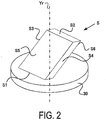
- FIG. 2 schematically illustrates an appearance diagram of an example of a specimen S placed on the placement stage 30.
- FIG. 2 illustrates a case where a flat plate member is placed as the specimen S having an incline with regard to the direction of the rotational axis Yr of the placement stage 30.
- a jig or the like is actually used so that the specimen S will not tip over, but the jig or the like is not illustrated in FIG. 2 .
- the jig in this embodiment is included in the inclusion region R1.
- the jig if the jig is rotated around the rotational axis Yr, the region that the jig passes through at least one time will be included in the inclusion region R1. Naturally, if the jig rotates around the rotational axis Yr, the jig can protrude out of the inclusion region R1. In this case, the data related to the jig can be removed from the image.
- the region that combines both the inclusion region when the jig rotates around the rotational axis Yr and the inclusion region when the specimen S rotates around the rotational axis Yr is taken as the inclusion region.
- the axes that connects the circular center of the cylindrical regions of the inclusion region of the jig and the inclusion region of the specimen S do not align, a cylindrical region can be set so as to include both cylindrical regions, and used as the inclusion region.
- the specimen S illustrated in FIG. 2 has mutually parallel planes S1 and S2, mutually parallel planes S3 and S4, and mutually parallel planes S5 and S6, and the specimen S is placed on the placement stage 30 such that the plane S1 is in contact with the placement stage 30.
- the preliminary inspection unit 54 controls the X-ray control unit 51 and the movement control unit 52, and causes X-rays to irradiate from the X-ray source 2 while rotating the specimen S that was placed on the placement stage 30 as illustrated in FIG. 2 .
- the detector 4 outputs X-ray projection image data for each predetermined rotational angle based on the transmitted X-rays irradiated from the X-ray source 2 and passed through the specimen S.
- the X-ray projection image data acquired during preliminary inspection may be less than the X-ray projection image data acquired for each rotational angle during the main inspection.
- the X-ray projection image data can be output from the detector 4 at larger rotational angles as compared to the case of the back projection image generated during the main inspection.
- the X-ray projection image data acquired during preliminary inspection may be more than or the same as the X-ray projection image data acquired for each rotational angle during the main inspection.
- An example where the X-ray projection image data is acquired at rotational angles of 90° is described below.
- FIG. 3 is diagram schematically illustrating the case where the specimen S that was placed on the placement stage 30 as illustrated in FIG. 2 is seen from above, or in other words from the Y-axis + side.
- FIG. 3(a) illustrates the case where the specimen S is at 0° with regard to the optical axis direction of the X-ray source 2, or in other words the Z-axis;
- FIG. 3(b) illustrates the case where the specimen S has been rotated 90° with the placement stage 30 in a counterclockwise direction from the condition of FIG. 3(a);
- FIG. 3(c) illustrates the case where the specimen S has been rotated 180° with the placement stage 30 in a counterclockwise direction from the condition of FIG. 3(a); and
- FIG. 3(a) illustrates the case where the specimen S is at 0° with regard to the optical axis direction of the X-ray source 2, or in other words the Z-axis
- FIG. 3(b) illustrates the case where the specimen S has been rotated 90°
- 3(d) illustrates the case where the specimen S has been rotated 270° with the placement stage 30 in a counterclockwise direction from the condition of FIG. 3(a) .
- the case where the plane S3 and plane S4 of the specimen S are orthogonal to the Z-axis as illustrated in FIG. 3(a) is referred to as having an angle of 0° between the X-ray source 2 and the specimen S.
- the region extracting unit 56 extracts the specimen region corresponding to the region that is included when the outer edge part of the specimen S rotates due to the rotation of the placement stage 30, from the X-ray projection image data using the X-ray projection image data acquired by the X-ray projection image data acquisition process.
- FIG. 4(a) illustrates the space surrounded by a distant part when the most distant part from the rotational axis Yr in the XZ plane is rotated at corresponding positions in the Y-axis direction in a case where the specimen S rotates around the rotational axis Yr on the placement stage 30.
- FIG. 4(a) representatively expresses the largest area of the surrounded space in the XZ plane at each position along the Y-axis direction as the first inclusion region T1.
- the region with the largest area at each position along the Y-axis direction is represented for extraction of the specimen region, but this is not a limitation.
- the average area in the XZ plane at a plurality of positions along the Y-axis direction can be used, and naturally in this case, it is also acceptable to not use all of the plurality of positions along the Y-axis direction.
- the region with the largest area is represented for each position along the Y-axis direction, but it is also acceptable to apply a predetermined ratio such as 90% or the like, for example, to the area.
- the predetermined ratio is 90%
- the predetermined ratio can also be applied to the area centered around the rotational axis Yr, for example.
- this also applies to the second inclusion region T2 described later. Therefore, the inclusion region R1 is determined based on the first inclusion region T1 and the second inclusion region T2. Therefore, the inclusion region R1 will differ based on the first inclusion region T1 and the second inclusion region T2 that is set.
- FIG. 4(a) is a diagram schematically illustrating the first inclusion region T1 as seen from above, or in other words from the Y-axis + side.
- the inclusion region T1 is circular centered around the rotational axis Yr.
- FIG. 4(b) is a diagram schematically illustrating the second inclusion region T2 for the case where a cylindrical shape is viewed from the X-axis - side, where the two inclusion regions T1 in FIG. 4(a) , or in other words the first inclusion region T1 on the Y-axis + side and the first inclusion region T1 on the Y-axis - side are the top surface and bottom surface. As illustrated in FIG.
- the second inclusion region T2 is rectangular with the outermost edge part of the specimen S where the distance from the intersecting point between the rotational axis Yr and the optical axis Zr is the largest set as the diagonal.
- the specimen S will be included inside a cylindrical region as illustrated in FIG. 4(c) at any rotational position.
- the region that the specimen S passes through at least one time is indicated by the first inclusion region T1 and the second inclusion region T2.
- the angle of rotation is not limited, and for example, a region where the rotation was 300° can also be used. Furthermore, a region where the specimen S was rotated 180° can be calculated, and then the inclusion region for the case of 360° rotation can be calculated from the region of 180° rotation.
- the region extraction unit 56 extracts the two-dimensional region corresponding to the projection region as the specimen region when the aforementioned inclusion region R1 is projected on the incident surface 41 of the detector 4 which is a plane parallel to the XY plane, by the procedures described below.
- the region extraction unit 56 performs differential processing using a Sobel filter or the like along the horizontal direction, or in other words along the X-axis direction, for example, with regard to the X-ray projection image data acquired when the angle between the X-ray source 2 and the specimen S is 0°, 90°, 180°, and 270°.
- the region extraction unit 56 specifies a boundary where the change in the intensity data of the X-rays detected by the detector 4 becomes steep, in all of the X-ray projection image data. This boundary corresponds to an end part of the specimen S in all of the X-ray projection image data.
- Synthesized data, composited data or integrated data is generated by synthesizing, compositing or integrating the X-ray projection image data after performing differential processing, and the specimen region is extracted by performing a binarizing process on the synthesize data.
- the region extraction unit 56 determined that the boundary where there was a steep change in the intensity data of the X-rays detected by the detector 4 was the end part of the specimen S, but there is no limitation to this example. For example, there are cases where a layer covered by the surface of the specimen S is difficult to detect with regard to the inside of the specimen S. In this case, the boundary where the change in the intensity of the X-rays detected by the detector 4 becomes steep and the position of the end part of the specimen S do not align. Therefore, a position that differs from the boundary detected by the detector 4 can be used as the end part of the specimen S. In other words, the region extraction unit 56 may extract a region that is larger than the detected region as the specimen region.
- the region extraction unit 56 may extract a region that is smaller than the specimen region that was detected as the specimen region.
- the region extraction unit 56 extracts the specimen region by specifying a boundary corresponding to an end part of the specimen S by extracting the contour from the synthesized data, but there is no limitation to this.
- FIG. 5 schematically illustrates a contour C of X-ray projection images D1 to D4 corresponding to the X-ray projection image data detected by the detector 4 when the angle between the X-ray source 2 and the specimen S is 0°, 90°, 180°, or 270°.
- the X-ray projection images D1, D2, D3, and D4 correspond to the cases where the angle between the X-ray source 2 and the specimen S is 0°, 90°, 180°, and 270°.
- FIG. 5(a) illustrates the contour C1 of the X-ray projection image when the angle between the X-ray source 2 and the specimen S is 0°.
- FIG. 5 schematically illustrates a contour C of X-ray projection images D1 to D4 corresponding to the X-ray projection image data detected by the detector 4 when the angle between the X-ray source 2 and the specimen S is 0°, 90°, 180°, or 270°.
- FIG. 5(b) illustrates the contour C2 of the X-ray projection image when the angle between the X-ray source 2 and the specimen S is 90°.
- FIG. 5(c) illustrates the contour C3 of the X-ray projection image when the angle between the X-ray source 2 and the specimen S is 180°.
- FIG. 5(d) illustrates the contour C4 of the X-ray projection image when the angle between the X-ray source 2 and the specimen S is 270°.
- the region extraction unit 56 synthesizes the X-ray projection image data from which the contours C1 to C4 were detected to generate synthesized data, and performs binary processing. When generating the synthesized data, the region extraction unit 56 performs synthesis such that the position of the detector 4 does not change, with regard to all of the X-ray projection image data.
- the X-ray projection image data is synthesized with reference to the rotational axis Yr when acquiring the X-ray projection image of FIG. 5(a) to FIG. 5(d) .
- the reference when synthesizing the X-ray projection image data is not limited to this.
- the X-ray projection image data may be combined such that of the various contours, the position of the contours of the region placed on the placement stage 30 are aligned in the Y direction.
- FIG. 5(e) schematically illustrates a synthesized image D5 and contours C1 to C4 corresponding to the synthesized data after binary processing.
- FIG. 5(e) illustrates a state in which the contours C1 to C4 are overlapped.
- the contours of the synthesized image obtained by overlapping the contours C1 to C4 on the XY plane is represented as C5.
- the region surrounded by the contour C5 is extracted as the specimen region R2 by the region extracting unit 56.
- the inclusion region R1 described above is set by a side which has the longest distance in the direction parallel to the X-axis direction, and the side which has the longest distance parallel to the Y-axis direction, of the specimen region R2 in the XY plane.
- the specimen region R2 is included in the region where the inclusion region R1 was projected on the incident surface 41 of the detector 4.
- the region extracting unit 56 is not limited to one that performs binary processing on the synthesized data that was generated, and synthesize data can be generated by synthesizing after performing binary processing on the differential process X-ray projection image data.
- the region extracting unit 56 can synthesize the X-ray projection image data to generate synthesize data, and then perform differential processing and binary processing on the synthesize data.
- the calculating unit 57 calculates the change amount for changing the distance in the Z-axis direction of the X-ray source 2 and the specimen S in main inspection. For example, there are cases where there is a desire to shorten the distance in the Z-axis direction between the X-ray source 2 and the specimen S, and to increase the size of the specimen S. In this case, for example, when the resolution of the detector 4 is fixed by the magnification, if the projected image of the specimen S on the detector 4 is enlarged, the internal structure can be inspected with higher resolution.
- the calculating unit 57 calculates the change amount in the position of the specimen S in preliminary inspection in order to change the distance in the Z-axis direction of the X-ray source 2 and the specimen S in main inspection, based on the position in the Z-axis direction of the specimen S at the time of the preliminary inspection and the size of the specimen region R2 on the detector 4.
- the distance in the Z-axis direction between the X-ray source 2 and the specimen S at the time of the main inspection is changed based on the size of the specimen region R2, but the distance in the Z-axis direction between the X-ray source 2 and the detector 4 at the time of the main inspection may be changed based on the size of the inclusion region R1.
- the size of the specimen region R2 or the size of the inclusion region R1 will change, and the distance in the Z-axis direction between the X-ray source 2 and the specimen S may also change based on the size of the aforementioned change.
- the size of the specimen region R2 may be expanded to 110%, and based upon the expanded region the distance in the Z-axis direction between the X-ray source 2 and the specimen S may be changed. Furthermore, for example, the size of the specimen region R2 may be shrunk to 90% and based upon the shrunk region the distance in the Z-axis direction between the X-ray source 2 and the specimen S may be changed.
- FIG. 6(a) is a diagram schematically illustrating the positional relationship between the X-ray source 2, the first inclusion region T1 of the specimen S, and the detector 4, as seen from above, or in other words from the Y-axis + side.
- the rotational position of the specimen S corresponds to the condition illustrated in FIG. 4(a) .
- the X-rays that pass through the range enclosed by L3 and L4 illustrated by the single dot dash line in FIG. 6(a) will pass through the inclusion region R1 of the specimen S, and will enter the detector 4.
- the X-rays that pass through the aforementioned inclusion region R1 will enter the incident range A2 in the X-axis direction illustrated in FIG. 6(a) on the incident surface 41 of the detector 4. Therefore, the projection magnification on the detector 4 by the specimen S will be larger when the specimen S is at P1, as compared to the case where the specimen S is at P0.
- P1x is a position that is closer to the Z-axis - side than P1 illustrated in FIG. 6(a) , or in other words, closer to the X-ray source 2.
- FIG. 6(b) is a diagram schematically illustrating the positional relationship between the X-ray source 2, the inclusion region R1 of the specimen S, and the detector 4, as seen from the X-axis - side.
- the rotational position of the specimen S corresponds to the condition illustrated in FIG. 4(b) .
- the X-rays that pass through the range enclosed by L5 and L6 illustrated by the dash line in FIG. 6(b) will pass through the inclusion region R1 of the specimen S, and will enter the detector 4.
- the X-rays that pass through the aforementioned inclusion region R1 will enter the incident range A3 in the Y-axis direction on the incident surface 41 of the detector 4.
- the X-rays that pass through the range enclosed by L7 and L8 illustrated by the single dot dash line in FIG. 6(b) will pass through the inclusion region R1 of the specimen S, and will enter the detector 4.
- the X-rays that pass through the aforementioned inclusion region R1 will enter the incident range A4 in the Y-axis direction illustrated in FIG. 6(b) on the incident surface 41 of the detector 4. Therefore, the projection magnification on the detector by the specimen S will be larger when the specimen S is at P3, as compared to the case where the specimen S is at P0.
- position P2y is the position of the specimen S where the maximum projection magnification can be obtained.
- the calculating unit 57 calculates the change amount of the distance in the Z-axis direction, or in other words the position of the specimen S, using the specimen region R2 that was extracted.
- the aforementioned 90 to 95% range can be used as the detection range from the entire region of the incident surface 41 of the detector 4.
- the change amount of the position of the specimen S, or in other words the distance in the Z-axis direction is calculated so that the inclusion region R1 is projected in the detection range of the detector 4.
- the maximum projection magnification when the inclusion region R1 is projected in the detection range is referred to as the effective maximum magnification.
- FIG. 7 schematically illustrates specimen region R2 on the synthesized image D5 corresponding to the synthesized data, extracted by the region extracting unit 56.
- FIG. 7 schematically illustrates a rectangular region R3 that circumscribes the specimen region R2.
- This rectangular region R3 is a region where the inclusion region R1 is projected on the detector 4.
- the calculating unit 57 calculates the shortest distance Dx in the X-axis direction of the distances from the outer edge part of the specimen region R2, or in other words to the limit of the detection range of the detector 4 from the rectangular region R3.
- the calculating unit 57 calculates the shortest distance Dy in the Y-axis direction of the distances from the outer edge part of the specimen region R2, or in other words to the limit of the detection range of the detector 4 from the rectangular region R3.
- the distance from the outer edge part in the X-axis + direction to the limit of the detection range is Dx
- the distance from the outer edge part in the Y-axis - direction to the limit in the detection range is Dy.
- the calculating unit 57 calculates a first changeable amount ⁇ Zw based on the ratio between the length of the segment Fw in the X-axis direction of the specimen region R2 and the length in the X-axis direction of the detection range of the detector 4.
- the length in the X-axis direction of the detection range of the detector 4 is the value Dw ⁇ ⁇ where the coefficient ⁇ is multiplied by the total region Dw in the X-axis direction of the incident surface 41 of the detector 4.
- the calculating unit 57 calculates a second changeable amount ⁇ Zh based on the ratio between the length of the segment Fh in the Y-axis direction of the specimen region R2 and the length in the Y-axis direction of the detection range of the detector 4.
- the length in the Y-axis direction of the detection range of the detector 4 is the value Dh ⁇ ⁇ where the coefficient ⁇ is multiplied by the total region Dh in the Y-axis direction of the incident surface 41 of the detector 4.
- the aforementioned ⁇ is the ratio that is used as the detection range for the incident surface 41 of the detector 4, and as described above, is generally 90 to 95%, or in other words a value of 0.9 to 0.95.
- the calculating unit 57 performs processing for matching the center of the specimen region R2 to the center of the incident surface 41 of the detector 4.
- an orthogonal coordinate system is set so as to be (0,0) in a left lower end portion of the incident surface 41 of the detector 4. Therefore, a coordinate of a right upper end portion of the incident surface 41 is (Dw, Dh).
- a coordinate of a left lower portion of the specimen region R2 is assumed (x0, y0), and a coordinate of a right upper portion is assumed (x0 + Fw, y0 + Fh).
- the calculating unit 57 assumes that the specimen region R2 is distributed to the left and right with regard to the center of the incident surface 41 in the X-axis direction.
- the calculating unit 57 assumes that the specimen region R2 is vertically distributed with regard to the center of the incident surface 41 in the Y-axis direction.
- the calculating unit 57 performs calculation of a first changeable amount ⁇ Zw and second changeable amount ⁇ Zh as described below. Note that the value of (Dh - Fh)/2 in the Y-axis direction is used when the placement stage 30 moves in the Y-axis direction as described hereinafter.
- a distance from the X-ray source 2 to the specimen S in the Z-axis direction is set to d0 at a position P0 of the specimen S during preliminary inspection. Furthermore, a distance between the X-ray source 2 and detector 4 in the Z-axis direction is set to d1. Furthermore, a distance from the X-ray source 2 to the specimen S when an effective maximum magnification is implemented in the X-axis direction, in other words, when the specimen S is at position P2 is set to d2.
- d 2 Fw / Dw ⁇ ⁇ ⁇ d 0
- Equation (2) the first changeable amount ⁇ Zw is expressed by Equation (2) below.
- Equation (3) d 0 1 ⁇ Fw / Dw ⁇ ⁇
- Equation (4) tan ⁇ 1 Fw / 2 / d 1
- Equation (5) an angle ⁇ w formed by Z axis and X-ray L3 when an effective maximum magnification is achieved in the X-axis direction is expressed by Equation (5) below, based on the distance d1 between the X-ray source 2 and detector 4 and the length Dw ⁇ ⁇ in the detection range of the detector 4.
- ⁇ w tan ⁇ 1 Dw ⁇ ⁇ / 2 / d 1
- the calculating unit 57 calculates the first changeable amount ⁇ Zw using Equation (7) below based on the aforementioned Equations (4) to (6).
- the calculating unit 57 calculates the first changeable amount ⁇ Zw based on the ratio between the length Fw in the X-axis direction of the specimen region R2 and the length Dw ⁇ ⁇ in the X-axis direction of the detection range on the incident surface 41.
- the second changeable amount ⁇ Zh is calculated based on the position where X-rays passing through an outer end portion Q1 or Q2 on the X-ray source 2 side of the inclusion region R1 is incident upon the incident surface 41.
- the inclusion region R1 has a cylindrical shape of radius R in the X-axis direction as described above, and therefore, a distance from the X-ray source 2 to the outer end portion Q1 in the Z-axis direction is d0 - R, and a distance from the X-ray source 2 to the outer end portion Q2 in the Z-axis direction is d3 - R.
- d 3 Fh / Dh ⁇ ⁇ ⁇ d 0 ⁇ R + R
- Equation (9) the second changeable amount ⁇ Zh is expressed by Equation (9) below.
- ⁇ Zh d 0 ⁇ d 3
- Equation (10) d 0 ⁇ R ⁇ 1 ⁇ Fh / Dh ⁇ ⁇
- Equation (11) An angle ⁇ h0 formed by the Z axis and X-ray L5 during preliminary inspection is expressed by Equation (11) below, based on the distance d1 between the X-ray source 2 and detector 4 and the length Fh in the Y-axis direction of the rectangular region R10.
- Equation (11) tan ⁇ 1 Fh / 2 / d 1
- Equation (12) an angle ⁇ h formed by the Z axis and X-ray L7 when an effective maximum magnification is achieved in the Y-axis direction is expressed by Equation (12) below, based on the distance d1 between the X-ray source 2 and detector 4 and length Dh ⁇ ⁇ in the Y-axis direction in the detection range of the detector 4.
- ⁇ h tan ⁇ 1 Dw ⁇ ⁇ / 2 / d 1
- second changeable amount ⁇ Zh needs to be calculated in the Y-axis direction, based on the position where X-rays passing through an outer end portion Q1 or Q2 on the X-ray source 2 side of the inclusion region R1 is incident upon the incident surface 41.
- the length H from the center of the inclusion region R1 to the outer end portion Q1 of the inclusion region R1 in the Y-axis direction can be expressed as in Equation (13), based on the distance d0 - R from the X-ray source 2 to the most X-ray source 2 side of the inclusion region R1, and the angle ⁇ h0 formed by the Z axis and X-ray L5.
- H d 0 ⁇ R ⁇ tan ⁇ h 0
- the calculating unit 57 calculates the second changeable amount ⁇ Zh using Equation (16) below based on Equations (11) to (15).
- the calculating unit 57 calculates the second changeable amount ⁇ Zh based on the ratio between the length Fh in the Y-axis direction of the specimen region R2 and the length Dh ⁇ ⁇ in the Y-axis direction of the detection range on the incident surface 41.
- the calculating unit 57 compares the first changeable amount ⁇ Zw and second changeable amount ⁇ Zh calculated by the aforementioned Equation (3) or Equation (7), and Equation (10) or Equation (16). As a result of comparing, the calculating unit 57 determines the smaller value to be the change amount ⁇ Z of the distance between the X-ray source 2 and specimen S. With the example illustrated in FIG. 6 , the calculating unit 57 uses the second changeable amount ⁇ Zh as the change amount ⁇ Z. In other words, the calculating unit 57 calculates the change amount ⁇ Z based on the ratio between length of the specimen region R2 along the smaller value of the distances Dx and Dy illustrated in FIG. 7 , and the length of the detection range of the detector 4.
- the movement control unit 52 controls the manipulator unit 36 to move the placement stage 30.
- the movement control unit 52 moves the placement stage 30 in the Y-axis direction.
- the movement control unit 52 determines a driving amount of the manipulator unit 36 based on the difference between y0 and (Dh - Fh)/2 described above.
- the movement control unit 52 moves the placement stage 30 in the Z-axis direction to change the distance between the specimen S and X-ray source 2.
- the movement control unit 52 determines the driving amount of the manipulator unit 36 based on the change amount ⁇ Z. Therefore, for the specimen S, an image of the entire specimen S at an effective maximum magnification in the detection range of the detector 4 on the generated back projection image, and the specimen S is moved to a position that does not impact or contact the portions of the X-ray device 100 during the main inspection.
- the X-ray device 100 After the placement stage 30 is moved by the manipulator unit 36 to a position where the main inspection is performed, the X-ray device 100 performs the main inspection on the specimen S. In other words, an image reconstruction process is performed with regard to the electrical signals output from the detector 4 based on the intensity of the X-rays that pass through the specimen S as the specimen S rotates through the predetermined angle in accordance with the rotation of the placement stage 30.
- X-ray projection image data of the specimen S is generated from the electrical signals output from the detector 4 as the specimen rotates at a smaller angle than during preliminary inspection, a back projection image is generated from the X-ray projection image data of the specimen S at a different detected rotation position, and a three-dimensional image that expresses the internal structure or cross-sectional structure of the specimen S is generated.
- the generated three-dimensional image is displayed on the display monitor 6, and then stored in a storage medium.
- a process illustrated in FIG. 9 is performed by executing a program by the control device 5.
- the program is stored in a memory (not illustrated in the drawing) in the control device 5, and is activated and executed by the control device 5.
- step S10 the preliminary inspection unit 54 of the control device 5 controls the X-ray control unit 51, movement control unit 52, and image generation unit 53, and acquires X-ray projection image data, and then the process proceeds to step S11.
- step S11 the region extraction unit 56 extracts the specimen region R2 corresponding to a region where the inclusion region R1 included when the specimen S rotates is projected on the incident surface 41 of the detector 4 from the acquired X-ray projection image data, and then the process proceeds to step S12.
- the calculating unit 57 calculates the change amount ⁇ Z of the specimen S in the Z-axis direction, based on the detection range of the detector 4 and outermost edge portion of the extracted specimen region R2, and then the process proceeds to step S 13.
- the movement control unit 52 moves the placement stage 30 along the Z-axis direction, based on calculated change amount ⁇ Z, and then the process proceeds to step S14. Note that the process from the aforementioned steps S10 to S13 is a process during preliminary inspection.
- step S14 the X-ray control unit 51, movement control unit 52, and image generation unit 53 control the X-ray source 2, rotation of the placement stage 30, and detector 4 to acquire X-ray projection image data, and then the process proceeds to step S 15.
- step S 15 the image generation unit 53 generates a back projection image using the acquired X-ray projection image data, and then the process proceeds to step S16.
- step S16 a three-dimensional image is displayed on the display monitor 6 or stored in a storage medium, based on the generated back projection image, and thus the process ends. Note that the process from the aforementioned steps S 14 to S16 is a process during the main inspection.
- the specimen region R2 corresponding to a region where the specimen S is projected onto the detector 4 based on rotation of the specimen S can be extracted from a plurality of X-ray projection image data output from the detector 4.
- the placement unit 3 was rotated between the X-ray source 2 and the detector 4, but the placements thereof are not limited to this.
- a line that links the center of the detector 4 and a light emitting point of the X-ray source 2 intersected with the rotational axis Yr of the placement unit 3 at 90° but this is not a limitation, and for example, the intersection can be at 10°, 20°, 30°, 40°, 50°, 60°, 70°, or 80°.
- a placement where the line that links the light emitting point of the X-ray source 2 and the center of the detector 4 can be oriented to intersect with the rotating surface of the placement unit 3, as disclosed in US 10/689,604 , may be acceptable.
- the inclusion region R1 for the specimen S was determined, and at least one position of the X-ray source 2, specimen S, and detector 4 can be changed so as to broaden the projection region of the specimen S at the detector 4.
- the aforementioned embodiment can be applied to an X-ray device with a plurality of X-ray sources as disclosed in US 2005/0,254,621 , US 7,233,644 , and the like for example.
- the aforementioned embodiment can also be applied to an X-ray device with a phase contrast system that evaluates slight phase shifting that occurs in X-rays during proceeding into the specimen, as disclosed in US 2010/0,220,834 .
- the aforementioned embodiment can also be applied to a helical type X-ray device that successively moves the specimen along a rotational axis that rotates the specimen, as disclosed in US 2001/802,468 , US 2007/685,985 , and the like for example.
- the structure manufacturing system of the present embodiment creates molded component such as, for example, a door portion, an engine portion, or a gear portion of an automobile, or an electronic component that incorporates an electrical circuit board and the like.
- FIG. 11 is a block diagram illustrating one example of a configuration of a structure manufacturing system 600 according to the present embodiment.
- the structure manufacturing system 600 is provided with the X-ray device 100 described in the first embodiment or alternate examples, a design device 610, a molding device 620, a control system 630, and a repair device 640.
- the design device 610 is a device used by a user when creating design information relating to a shape of a structure and performs design processing for creating and storing the design information.
- the design information is information indicating coordinates of each position of the structure.
- the design information is output to the molding device 620 and the control system 630, which is described below.
- the molding device 620 performs molding processing for creating and molding the structure using the design information created by the design device 610.
- a molding device 620 that performs at least one of laminating which is representative in 3D-printer technology, casting, forging, and cutting is also included in one aspect of the present invention.
- the X-ray device 100 performs a measuring process for measuring a shape of the structure molded by the molding device 620.
- the X-ray device 100 outputs to the control system 630 information indicating coordinates of the structure ("shape information" hereinbelow), which is a measurement result of measuring the structure.
- the control system 630 is provided with a coordinate storage unit 631 and an inspection unit 632.
- the coordinate storage unit 631 stores the design information created by the design device 610 described above.
- the inspection unit 632 determines whether the structure molded by the molding device 620 is molded according to the design information created by the design device 610. In other words, the inspection unit 632 determines whether the molded structure is a non-defective product. In this case, the inspection unit 632 reads the design information stored in the coordinate storage unit 631 and performs inspection processing comparing the design information and the shape information input from the X-ray device 100. For the inspection processing, the inspection unit 632 compares, for example, the coordinates indicated by the design information and the corresponding coordinates indicated by the shape information and determines that the molded structure is a non-defective product molded if the result of this inspection processing shows the the coordinates of the design information and the coordinates of the shape information match.
- the inspection unit 632 determines whether a difference between the coordinates is within a predetermined range and determines that the molded structure is a repairable defective product if this difference is within the predetermined range.
- the inspection unit 632 When it determines that the molded structure is a repairable defective product, the inspection unit 632 outputs to the repair device 640 repair information indicating a defective area and a repair amount.
- the defective area is the coordinates of the shape information that do not match the coordinates of the design information
- the repair amount is the difference between the coordinates of the design information and the coordinates of the shape information at the defective area.
- the repair device 640 performs repair processing for re-machining the defective area of the structure based on the input repair information.
- the repair device 640 performs again processing similar to the molding processing performed by the molding device 620.
- the processing performed by the structure manufacturing system 600 is described with reference to the flowchart illustrated in FIG. 12 .
- step S111 the design device 610 is used when the user designs the structure and the design information relating to the shape of the structure is created and stored by the design processing; the flow then proceeds to step S 112.
- the present invention is not limited to only the design information created by the design device 610; when design information already exists, inputting this design information to acquire the design information is also included in one aspect of the present invention.
- step S 112 the molding device 620 creates and molds the structure based on the design information by the molding processing; the flow then proceeds to step S113.
- step S113 the X-ray device 100 performs measurement processing to measure the shape of the structure and outputs the shape information; the flow then proceeds to step S 114.
- the inspection unit 632 performs the inspection processing to compare the design information created by the design device 610 and the shape information measured and output by the X-ray device 100; the flow then proceeds to step S 115.
- the inspection unit 632 determines based on the result of the inspection processing whether the structure molded by the molding device 620 is a non-defective product. When the structure is a non-defective product, that is, when the coordinates of the design information and the coordinates of the shape information match, an affirmative determination is made at step S 115; the processing then ends.
- step S 115 If the structure is a defective product, that is, when the coordinates of the design information and the coordinates of the shape information do not match or when coordinates that are not present in the design information are detected, a negative determination is made in step S 115; the flow then proceeds to step S 116.
- step S116 the inspection unit 632 determines whether the defective area of the structure is repairable.
- the defective area is unrepairable, that is, when the difference between the coordinates of the design information and the coordinates of the shape information exceeds the predetermined range, a negative determination is made in step S116; the processing then ends.
- the defective area is repairable, that is, when the difference between the coordinates of the design information and the coordinates of the shape information are within the predetermined range, an affirmative determination is made in step S116; the flow then proceeds to step S 117.
- the inspection unit 632 outputs the repair information to the repair device 640.
- the repair device 640 performs the repair processing on the structure based on the input repair information; the flow then returns to step S 113. Note that as described above, the repair device 640 performs again processing similar to the molding processing performed by the molding device 620 in the repair processing.
- the structure manufacturing system according to the second embodiment described above provides the following functions and effects.
Landscapes
- Physics & Mathematics (AREA)
- Health & Medical Sciences (AREA)
- General Physics & Mathematics (AREA)
- Immunology (AREA)
- Analytical Chemistry (AREA)
- Biochemistry (AREA)
- General Health & Medical Sciences (AREA)
- Chemical & Material Sciences (AREA)
- Life Sciences & Earth Sciences (AREA)
- Pathology (AREA)
- Pulmonology (AREA)
- Engineering & Computer Science (AREA)
- Nuclear Medicine, Radiotherapy & Molecular Imaging (AREA)
- Radiology & Medical Imaging (AREA)
- Theoretical Computer Science (AREA)
- Electromagnetism (AREA)
- Toxicology (AREA)
- Analysing Materials By The Use Of Radiation (AREA)
Abstract
Description
- The present invention relates to an X-ray inspection device, X-ray inspection method, and a method of manufacturing a structure.
- An X-ray apparatus such as that disclosed in the Patent Literature mentioned below, which irradiates a specimen with X-rays and detects transmitted X-rays that have been transmitted through the specimen, is known as a device that obtains information of the interior of the specimen in a non-destructive manner.
- Patent Literature 1:
US 2009/0,268,869 - When a specimen is inspected using X-rays, there is a possibility that inspection failure will occur due to collision between the X-ray source and the specimen, for example, depending on the distance between the X-ray source and the specimen. Furthermore, there is a possibility that inspection defects will occur due to collision between the specimen and the detector, for example, depending on the distance between the specimen and the detector. Furthermore, there is a possibility that inspection defects will occur due to collision between the specimen, the X-ray source, and the detector, for example, depending on the distance between the X-ray source, the specimen, and the detector. Furthermore, when projecting a projection image of the specimen on the detector, detection of the projected image across a broad range on the detector is preferable.
- According to the first aspect of the present invention, the X-ray inspection device includes a radiation source that irradiates X-rays toward a specimen that is rotated, a detector that detects transmitted X-rays irradiated by the radiation source and passed through the specimen, and output a plurality of detection data for each angle of rotation, and a region extracting unit that extracts a region where the specimen is projected onto the detector, using the plurality of detection data.
- According to the second aspect of the present invention, the X-ray inspection device according to the first aspect preferably may include a change unit that changes a relative distance between the specimen and the radiation source, based on the region extracted by the region extracting unit.
- According to a third aspect of the present invention, the X-ray inspection device of the second aspect preferably includes a calculating unit that calculates a change amount in the relative distance between the specimen and the radiation source, based on the region extracted by the region extracting unit, and the changing unit preferably changes the relative distance based on the change amount that was calculated by the calculating unit.
- According to the fourth aspect of the present invention, the X-ray inspection device according to any one of the first through third aspects is preferably configured such that the region extracting unit generates synthesized data by synthesizing a plurality of detection data, and extracts an outer edge unit of the specimen in the synthesized data as the region.
- According to the fifth aspect of the present invention, the X-ray inspection device according to the fourth aspect is preferably configured such that the region extracting unit generates the synthesized data, and extracts the region by binarizing the synthesized data.
- According to the sixth aspect of the present invention, the X-ray inspection device according to the fifth aspect is preferably configured such that the region extracting unit extracts an outermost edge part in a first direction where a distance to the detection range of the detector is shortest in the first direction that is orthogonal to an axis of rotation, and an outermost edge part in a second direction where the distance to the detection range of the detector is shortest in the second direction along the axis of rotation, among the outer edge parts of the extracted region,; and the calculating unit calculates the change amount in the relative distance based on an outermost edge part where the distance to the detection range of the detector is shortest among the outermost edge part in the first direction and the outermost edge part in the second direction.
- According to the seventh aspect of the present invention, the X-ray inspection device according to the sixth aspect is preferably configured such that the calculating unit calculates the change amount in the relative distance based on one of a first ratio between a first segment and the length in the first direction of the detection region of the detector, and a second ratio between a second segment and the length in the second direction of the detection range of the detector, in a rectangular region surrounded by the first segment in the first direction that contacts the outer edge part of the extracted region in synthesized data and the second segment in the second direction that intersects with the first direction and contacts the outer edge part of the extracted region.
- According to the eighth aspect of the present invention, the X-ray inspection device of the seventh aspect preferably has a configuration where the calculating unit compares a first change amount of the relative distance based on the first ratio with a second change amount of the relative distance based on the second ratio, and calculates a smaller value of the first and second change amounts as the change amount of the relative distance.
- According to the ninth aspect of the present invention, the X-ray inspection device of the seventh or eighth aspect preferably has a configuration where the change unit changes the relative distance by moving the specimen or the radiation source along a direction of an optical axis of the radiation source, based on the change amount in the relative distance calculated by the calculating unit.
- According to the tenth aspect of the present invention, the X-ray inspection device of the ninth aspect preferably includes a rotating placement unit that places and rotates the specimen, wherein the change unit changes the relative distance between the specimen and the radiation source by moving the rotating placement unit along the direction of the optical axis of the radiation source.
- According to the eleventh aspect of the present invention, the X-ray inspection device according to the tenth aspect preferably has a configuration where the change unit changes the relative positional relationship between the specimen and the radiation source by moving the rotating placement unit along a direction of a rotational axis such that a center in the second direction of the region in the synthesized data aligns with a center point of the detection range of the detector in the second direction.
- With the twelfth aspect of the present invention, the X-ray inspection device according to any one of the second through eleventh aspects preferably further includes an image generating unit that generates a back projection image of the specimen based on the plurality of detection data detected and output by the detector based on an irradiation of the X-rays from the radiation source, after the relative distance between the radiation source and the specimen has been changed by the change unit.
- With the thirteenth aspect of the present invention, the X-ray inspection device includes a radiation source that irradiates X-rays onto the specimen, a detector that detects transmitted X-rays irradiated from the radiation source and passed through the specimen, and outputs detection data, a preliminary inspection unit that calculates a change amount in a relative distance between the specimen and the radiation source, using the detection data, and changes the relative distance between the specimen and the radiation source based on the change amount of the relative distance that was calculated, and an image generating unit that generates a back projection image of the specimen using the detection data output from the detector that detects the transmitted X-rays from the radiation source after the relative distance was changed by the preliminary inspection unit.
- With the fourteenth aspect of the present invention, the X-ray inspection device of the thirteenth aspect preferably has a configuration where the radiation source irradiates X-rays onto a specimen that is rotated, the detector outputs a plurality of detection data for each rotated angle, and the preliminary inspection unit extracts a region where the specimen is projected on the detector from the plurality of detection data, calculates the change amount in the relative distance based on the region where the specimen is projected, and changes the relative distance based on the change amount that was calculated.
- According to the fifteenth aspect of the present invention, the X-ray inspection method includes irradiating X-rays from the radiation source onto a specimen that is rotated, detecting transmitted X-rays irradiated, and passed through the specimen, outputting a plurality of detection data for each angle of rotation, and extracting a region where the specimen is projected, using the plurality of detection data.
- According to the sixteenth aspect of the present invention, in the X-ray inspection method according to the fifteenth aspect a relative distance between the specimen and the radiation source is preferably changed, based on the extracted region.
- According to the seventeenth aspect of the present invention, the X-ray inspection method of the sixteenth aspect preferably further includes calculating a change amount in the relative distance between the specimen and the radiation source, based on the extracted region, and changes the relative distance in accordance with the change amount that was calculated.
- With the eighteenth aspect of the present invention, the X-ray inspection method according to the seventeenth aspect preferably includes generating a back projection image of the specimen based on the plurality of detection data detected and output based on an irradiation of the X-rays, after the relative distance between the radiation source and the specimen has been changed.
- According to the nineteenth aspect of the present invention, a method for manufacturing structures includes creating design information regarding a shape of a structure; creating the structure based on the design information; acquiring shape information by measuring the shape of the created structure by using the X-ray inspection device according to any one of the first through fourteenth aspects; and comparing the acquired shape information with the design information.
- With the twentieth aspect of the present invention, the method for manufacturing structures according to the nineteenth aspect preferably performs refabrication of the structure by implementation based on the comparison results between the shape information and the design information.
- With the twenty-first aspect of the present invention, in the method for manufacturing structures according to the twentieth aspect, the refabrication of the structure preferably includes performing creation of the structure again based on the design information.
-
-
FIG. 1 is a block diagram illustrating one example of a configuration of an X-ray apparatus according to a first embodiment. -
FIG. 2 is a diagram schematically illustrating the appearance of the specimen placed on a placement base. -
FIG. 3 is diagram schematically illustrating the appearance of the specimen placed on a placement base seen from above. -
FIG. 4 is diagram schematically illustrating an inclusion region where the specimen is included by rotating the specimen. -
FIG. 5 is diagram schematically illustrating a contour of the specimen detected in the X-ray projection image data acquired when the angle between the X-ray source and the specimen is 0°, 90°, 180°, and 270°. -
FIG. 6 is diagram schematically illustrating the positional relationship between the X-ray source, the inclusion region of the specimen, and the detector, in order to describe the concept for calculating the change amount. -
FIG. 7 is a diagram schematically illustrating the specimen region that was extracted from the synthesis data. -
FIG. 8 is a diagram describing calculation of the change amount when the center of the specimen region does not match the center of the synthesized data. -
FIG. 9 is a flowchart describing the operation of the X-ray apparatus. -
FIG. 10 is diagram schematically illustrating the positional relationship between the X-ray source and the specimen for an alternate example. -
FIG. 11 is a block diagram illustrating a configuration of a structure manufacturing system according to a second embodiment. -
FIG. 12 is a flowchart describing the operation of a structure manufacturing system. - An X-ray apparatus according to a first embodiment is described while referring to the drawings. The X-ray apparatus non-destructively acquires the internal information, for example, of the internal configuration or the like of a specimen by irradiating X-rays at the specimen and detecting the transmitted X-ray passing through the specimen. If the specimen is an industrial component such as a mechanical component or an electronic component or the like, the X-ray apparatus is referred to as an industrial X-ray CT (Computed Tomography) inspection device that inspects an industrial product.
- The present embodiment is for describing the gist of the invention in detail for understanding, and does not limit the present invention unless explicitly stated.
-
FIG. 1 is a drawing schematically illustrating an example of a configuration ofX-ray device 100 according to the present embodiment. Note that for convenience of description, a coordinate system composed of an X-axis, Y-axis, and a Z-axis is set as is illustrated in the drawing. - The
X-ray device 100 is provided with ahousing 1, anX-ray source 2, aplacement unit 3, adetector 4, acontrol device 5, adisplay monitor 6, and a frame 8. Thehousing 1 is disposed such that a bottom surface is substantially parallel to, or in other words horizontally, the XZ plane on the floor surface of a factory or the like and internally houses anX-ray source 2,placement unit 3,detector 4, and frame 8. Thehousing 1 includes lead as a material so that X-rays do not leak to the outside. - The
X-ray source 2 emits X-rays in a cone shape (a so-called "cone beam") in the Z-axis + direction along an optical axis Zr parallel to the Z-axis with the emission point Q illustrated inFIG. 1 as the vertex, based on control by acontrol device 5. The emission point Q corresponds to the focal point of theX-ray source 2. The optical axis Zr connects the emission point Q, which is the focal point of theX-ray source 2, with the center of the imaging region of thedetector 4 described hereinafter. Note that for theX-ray source 2, instead of emitting X-rays in a cone shape, an X-ray source that emits X-rays in a fan shape (a so-called "fan beam") is also included in one aspect of the present invention. TheX-ray source 2 can emit, for example, at least one of: an approximately 50 eV ultrasoft X-ray, an approximately 0.1 to 2 keV soft X-ray, an approximately 2 to 20 keV X-ray, and a hard X-ray with at least approximately 20 to 100 keV. Furthermore, theX-ray source 2 may emit X-rays of 1 to 10 Mev, for example. - The
placement unit 3 has aplacement stage 30 on which the specimen S is placed, and amanipulator 36 made from a rotation drive unit 32, a Y-axis movement unit 33, anX-axis movement unit 34, and a Z-axis movement unit 35, provided further to the Z-axis + side than theX-ray source 2. Theplacement stage 30 is provided so as to be rotatable by the rotation drive unit 32, and when themanipulator 36 moves in the X-axis, Y-axis, or Z-axis directions due to the rotation drive unit 32, theplacement stage 30 also moves in conjunction. Furthermore, the surface of theplacement stage 30 has an index or the like that is used for positioning when a specimen S is placed on the center of rotation or the like when rotationally driven by the rotation drive unit 32. - The rotation drive unit 32 is, for example, configured to include an electric motor or the like, and is parallel to the Y-axis and rotates the
placement stage 30 with an axis passing through the center of theplacement unit 30 as a rotational axis Yr via the rotational force generated by an electric motor controlled and driven by acontrol device 5, described hereinafter. In other words, the rotation drive unit 32 changes the relative direction of theplacement stage 30 and the specimen S on theplacement stage 30 with regard to the X-rays emitted from theX-ray source 2 by rotating theplacement stage 30. The Y-axis movement unit 33, theX-axis movement unit 34, and the Z-axis movement unit 35 are controlled by thecontrol device 5, and each move theplacement stage 30 in the X-axis direction, the Y-axis direction, and the Z-axis direction respectively so that the specimen S is positioned in the emission range of the X-rays emitted by theX-ray source 2. The Z-axis movement unit 35 is controlled by thecontrol unit 5, and moves theplacement stage 30 in the Z-axis direction so that the distance from theX-ray source 2 to the specimen S is a distance where the projection image of the specimen S is at the desired magnification ratio. -
A Y position detector 331,X position detector 341, andZ position detector 351 are encoders that detect the corresponding position of theplacement stage 30 that has moved in the X-axis direction, Y-axis direction, and Z-axis direction by the Y-axis movement unit 33,X-axis movement unit 34, and Z-axis movement unit 35, and that output a signal indicating the detected position to acontrol device 5. Incidentally, in the following description, the position of theplacement stage 30 detected by theY position detector 331,X position detector 341, and theZ position detector 351 is referred to as the detected movement position. - The rotation position detector 321 detects the rotation position of the
placement stage 30 that rotates around the rotational axis Yr by the rotation drive unit 32. Incidentally, in the following description, the rotation position of theplacement stage 30 detected by the rotation position detector 321 is referred to as the detected rotation position. The detected rotation position expresses the relative direction of the specimen S on theplacement stage 30 with regard to the X-rays emitted from theX-ray source 2. - The
detector 4 is provided further to the Z-axis + side than theX-ray source 2 and theplacement stage 30. In other words, theplacement stage 30 is provided between theX-ray source 2 and thedetector 4 in the Z-axis direction. Thedetector 4 has anincident surface 41 parallel to the XY plane, and X-rays including the transmitted X-rays emitted from theX-ray source 2 and have passed through the specimen S placed on theplacement stage 30 are incident upon theincident surface 41. Thedetector 4 is configured by a scintillator unit that includes a commonly known scintillation substance, a photomultiplier tube, and a light receiving unit, and the like. Thedetector 4 converts the energy of X-rays incident on theincident surface 41 of the scintillator unit to light energy such as visible light, ultraviolet light, or the like, amplifies it with the photomultiplier tube, converts the amplified light energy to electric energy with the aforementioned light receiving unit, and outputs the electric energy as an electric signal to thecontrol device 5. Thedetector 4 has a composition wherein the scintillator unit, the photomultiplier tube, and the light receiving unit are each divided into a plurality of pixels, and the pixels are arranged two dimensionally. Thus, an intensity distribution for the X-rays emitted from theX-ray source 2 and have passed through the specimen S can be acquired at one time. Incidentally, a predetermined range, for example, a range of approximately 90 to 95% of the total region of theincident surface 41 is the detection range, and a back projection image or the like of the specimen S described below is created based on the transmitted X-rays detected in the detection range. The size of the detection range is not limited to approximately 90 to 95% of the total region of theincident surface 41, and can be determined based on a balance between the maximum magnification image of the specimen S and the back projection image, and based on a range where the specimen S will not collide with the various components of theX-ray device 100 when generating a back projection image at maximum magnification, and the like. Furthermore, the size of the detection range can be set by the user to a desired size. - Note that the
detector 4 may convert the energy of incident X-rays to electric energy and output it as an electric signal without converting to light energy. Thedetector 4 is not limited to those where the pixels are arranged two dimensionally. Thedetector 4 has anincident surface 41 that expands in the X-axis direction, for example, on a surface parallel to the XY plane, but theincident surface 41 can be configured by a line sensor where a single pixel is provided in the Y-axis direction. The arrangement direction of the line sensor pixels is not limited to the Y-axis direction, and the arrangement can be in the X-axis direction. Note that as thedetector 4, a composition may be had wherein the scintillator unit is directly formed on the light receiving unit without providing a photomultiplier tube. - The frame 8 supports the
X-ray source 2, theplacement unit 3, and thedetector 4. The frame 8 is constructed to have sufficient rigidity. Thus, it is possible to stably support theX-ray source 2, theplacement unit 3, and thedetector 4 while acquiring a captured image of the specimen S. The frame 8 is supported by thehousing 1 through ananti-vibration mechanism 81 to prevent vibration generated on the outside from being transmitted as is to the frame 8. - The
control device 5 has a microprocessor, surrounding circuits, and the like, and controls various units of theX-ray device 100 by reading and executing a control program stored beforehand on a storage medium not illustrated in the drawings, for example, flash memory or the like. Thecontrol device 5 is provided with an X-ray control unit 51, amovement control unit 52, animage generation unit 53, apreliminary inspection unit 54, a work memory 55, aregion extracting unit 56, and a calculating unit 57. The X-ray control unit 51 controls the behavior of theX-ray source 2, and themovement control unit 52 controls the movement behavior of themanipulator 36. Theimage generating unit 53 generates an X-ray projection image based on the X-ray projection image data of the specimen S which is the detection data based on the electric signal output from thedetector 4 based on the intensity of X-rays that pass through the specimen S. Furthermore, theimage generating part 53 executes an image reconstruction process that generates a back projection image with regard to the electric signals output from thedetector 4 based on the intensity of the X-rays that pass through the specimen S as the specimen S rotates through the predetermined angle in accordance with the rotation of theplacement stage 30, and generates a three-dimensional image of the specimen S. Processes for generating the back projection image include a back projection method, filtered back projection method, iterative reconstruction method, and the like. - The
preliminary inspection unit 54 controls the X-ray control unit 51,movement control unit 52,region extracting unit 56, and calculating unit 57, and executes the preliminary inspection. The preliminary inspection is performed in order to calculate the distance between the specimen S and theX-ray source 2, and to position the specimen S at the calculated distance, so that the maximum magnification of the specimen S can be generated in the back projection image. Theregion extracting unit 56 extracts the specimen region corresponding to the outer edge part of the specimen S as the specimen S rotates by the rotation of theplacement stage 30 from the X-ray projection image data of the specimen S at different detected rotation positions. The calculating unit 57 calculates the change amount of the position in the Z-axis direction of the specimen S during preliminary inspection, in other words, the change amount of the distance in the Z-axis direction between the specimen S and theX-ray source 2, based on the specimen region that was extracted by theregion extracting unit 56. Thepreliminary inspection unit 54 controls themovement control unit 52 to move theplacement stage 30 in the Z-axis direction in accordance with the change amount calculated by the calculating unit 57. Incidentally, the details of themovement control unit 52 of thecontrol device 5,image generation unit 53,preliminary inspection unit 54,region extracting unit 56, and calculating unit 57 are described below. - The work memory 55 is configured by volatile storage media, for example, and the X-ray projection image data generated by the
image generation part 53 is stored temporarily. - The function of the
X-ray device 100 is described below. TheX-ray device 100 changes the distance in the Z-axis direction between theX-ray source 2 and the specimen S based on the specimen region extracted from the X-ray projection image data generated by irradiating from theX-ray source 2 during preliminary inspection. TheX-ray device 100 changes the distance between theX-ray source 2 and the specimen S by preliminary inspection, and generates a back projection image from the X-ray projection image data generated by irradiating from theX-ray source 2 as the main inspection. The main functions of theX-ray device 100 during preliminary inspection are described below. - Preliminary inspection is performed prior to the main inspection. The preliminary inspection is performed in order to set the distance in the Z-axis direction between the
X-ray source 2 and theplacement stage 30 so that the specimen region can be a predetermined size on thedetection surface 41 of thedetector 4. The preliminary inspection of the present embodiment is performed by the following processes (1) to (4). - (1) Acquisition process of X-ray projection image data
- (2) Extraction process of the specimen region
- (3) Calculation process of the change amount
- (4) Movement process of the specimen S based on the change amount
- The explanation is divided below into (1) to (4). Incidentally, the details about the specimen region and the change amount are described below.
- The specimen S is placed on the
placement stage 30 by the user, and when execution of preliminary inspection is instructed by operating an operating unit not illustrated in the drawings, thepreliminary inspection unit 54 of thecontrol unit 5 begins preliminary inspection of the specimen S. Incidentally, when the user places the specimen S on theplacement stage 30, the aforementioned indicator or the like provided on the surface of theplacement stage 30 is used as a landmark, and thus the specimen S can be placed such that the rotational center of theplacement stage 30, or in other words the rotational axis Yr is essentially in line with the center of a projection image circumscribed circle when the specimen S is projected on the upper surface of theplacement stage 30. -
FIG. 2 schematically illustrates an appearance diagram of an example of a specimen S placed on theplacement stage 30.FIG. 2 illustrates a case where a flat plate member is placed as the specimen S having an incline with regard to the direction of the rotational axis Yr of theplacement stage 30. Incidentally, for the case illustrated inFIG. 2 , a jig or the like is actually used so that the specimen S will not tip over, but the jig or the like is not illustrated inFIG. 2 . Incidentally, the jig in this embodiment is included in the inclusion region R1. In other words, if the jig is rotated around the rotational axis Yr, the region that the jig passes through at least one time will be included in the inclusion region R1. Naturally, if the jig rotates around the rotational axis Yr, the jig can protrude out of the inclusion region R1. In this case, the data related to the jig can be removed from the image. Furthermore, if the jig protrudes out of the inclusion region R1 when the jig is rotated around the rotational axis Yr, the region that combines both the inclusion region when the jig rotates around the rotational axis Yr and the inclusion region when the specimen S rotates around the rotational axis Yr is taken as the inclusion region. Furthermore, if the axes that connects the circular center of the cylindrical regions of the inclusion region of the jig and the inclusion region of the specimen S do not align, a cylindrical region can be set so as to include both cylindrical regions, and used as the inclusion region. The specimen S illustrated inFIG. 2 has mutually parallel planes S1 and S2, mutually parallel planes S3 and S4, and mutually parallel planes S5 and S6, and the specimen S is placed on theplacement stage 30 such that the plane S1 is in contact with theplacement stage 30. - The
preliminary inspection unit 54 controls the X-ray control unit 51 and themovement control unit 52, and causes X-rays to irradiate from theX-ray source 2 while rotating the specimen S that was placed on theplacement stage 30 as illustrated inFIG. 2 . Thedetector 4 outputs X-ray projection image data for each predetermined rotational angle based on the transmitted X-rays irradiated from theX-ray source 2 and passed through the specimen S. Incidentally, the X-ray projection image data acquired during preliminary inspection may be less than the X-ray projection image data acquired for each rotational angle during the main inspection. In other words, the X-ray projection image data can be output from thedetector 4 at larger rotational angles as compared to the case of the back projection image generated during the main inspection. Naturally, the X-ray projection image data acquired during preliminary inspection may be more than or the same as the X-ray projection image data acquired for each rotational angle during the main inspection. An example where the X-ray projection image data is acquired at rotational angles of 90° is described below. -
FIG. 3 is diagram schematically illustrating the case where the specimen S that was placed on theplacement stage 30 as illustrated inFIG. 2 is seen from above, or in other words from the Y-axis + side.FIG. 3(a) illustrates the case where the specimen S is at 0° with regard to the optical axis direction of theX-ray source 2, or in other words the Z-axis;FIG. 3(b) illustrates the case where the specimen S has been rotated 90° with theplacement stage 30 in a counterclockwise direction from the condition ofFIG. 3(a); FIG. 3(c) illustrates the case where the specimen S has been rotated 180° with theplacement stage 30 in a counterclockwise direction from the condition ofFIG. 3(a); and FIG. 3(d) illustrates the case where the specimen S has been rotated 270° with theplacement stage 30 in a counterclockwise direction from the condition ofFIG. 3(a) . Incidentally, in the following explanation, the case where the plane S3 and plane S4 of the specimen S are orthogonal to the Z-axis as illustrated inFIG. 3(a) , is referred to as having an angle of 0° between theX-ray source 2 and the specimen S. - The
region extracting unit 56 extracts the specimen region corresponding to the region that is included when the outer edge part of the specimen S rotates due to the rotation of theplacement stage 30, from the X-ray projection image data using the X-ray projection image data acquired by the X-ray projection image data acquisition process. - If the specimen S rotates on the
placement stage 30 as illustrated inFIG. 3(a) to FIG. 3(d) , the inclusion region that includes the farthest portion from the center of rotation of the specimen S is illustrated inFIG. 4. FIG. 4(a) illustrates the space surrounded by a distant part when the most distant part from the rotational axis Yr in the XZ plane is rotated at corresponding positions in the Y-axis direction in a case where the specimen S rotates around the rotational axis Yr on theplacement stage 30. -
FIG. 4(a) representatively expresses the largest area of the surrounded space in the XZ plane at each position along the Y-axis direction as the first inclusion region T1. Incidentally, the region with the largest area at each position along the Y-axis direction is represented for extraction of the specimen region, but this is not a limitation. For example, the average area in the XZ plane at a plurality of positions along the Y-axis direction can be used, and naturally in this case, it is also acceptable to not use all of the plurality of positions along the Y-axis direction. Furthermore, the region with the largest area is represented for each position along the Y-axis direction, but it is also acceptable to apply a predetermined ratio such as 90% or the like, for example, to the area. If the predetermined ratio is 90%, the predetermined ratio can also be applied to the area centered around the rotational axis Yr, for example. Naturally, this also applies to the second inclusion region T2 described later. Therefore, the inclusion region R1 is determined based on the first inclusion region T1 and the second inclusion region T2. Therefore, the inclusion region R1 will differ based on the first inclusion region T1 and the second inclusion region T2 that is set. -
FIG. 4(a) is a diagram schematically illustrating the first inclusion region T1 as seen from above, or in other words from the Y-axis + side. The inclusion region T1 is circular centered around the rotational axis Yr.FIG. 4(b) is a diagram schematically illustrating the second inclusion region T2 for the case where a cylindrical shape is viewed from the X-axis - side, where the two inclusion regions T1 inFIG. 4(a) , or in other words the first inclusion region T1 on the Y-axis + side and the first inclusion region T1 on the Y-axis - side are the top surface and bottom surface. As illustrated inFIG. 4(b) , the second inclusion region T2 is rectangular with the outermost edge part of the specimen S where the distance from the intersecting point between the rotational axis Yr and the optical axis Zr is the largest set as the diagonal. In other words, if the specimen S is rotated in conjunction with theplacement stage 30, the specimen S will be included inside a cylindrical region as illustrated inFIG. 4(c) at any rotational position. With the present embodiment, when the specimen S is placed on theplacement stage 30 as illustrated inFIG. 4 and then the specimen S is rotated 360° around the rotational axis Yr, the region that the specimen S passes through at least one time is indicated by the first inclusion region T1 and the second inclusion region T2. Incidentally, with the present embodiment, an example where the specimen S was rotated 360° was described, but the angle of rotation is not limited, and for example, a region where the rotation was 300° can also be used. Furthermore, a region where the specimen S was rotated 180° can be calculated, and then the inclusion region for the case of 360° rotation can be calculated from the region of 180° rotation. - The
region extraction unit 56 extracts the two-dimensional region corresponding to the projection region as the specimen region when the aforementioned inclusion region R1 is projected on theincident surface 41 of thedetector 4 which is a plane parallel to the XY plane, by the procedures described below. In other words, theregion extraction unit 56 performs differential processing using a Sobel filter or the like along the horizontal direction, or in other words along the X-axis direction, for example, with regard to the X-ray projection image data acquired when the angle between theX-ray source 2 and the specimen S is 0°, 90°, 180°, and 270°. By this processing, theregion extraction unit 56 specifies a boundary where the change in the intensity data of the X-rays detected by thedetector 4 becomes steep, in all of the X-ray projection image data. This boundary corresponds to an end part of the specimen S in all of the X-ray projection image data. Synthesized data, composited data or integrated data is generated by synthesizing, compositing or integrating the X-ray projection image data after performing differential processing, and the specimen region is extracted by performing a binarizing process on the synthesize data. - Incidentally, with the present embodiment, the
region extraction unit 56 determined that the boundary where there was a steep change in the intensity data of the X-rays detected by thedetector 4 was the end part of the specimen S, but there is no limitation to this example. For example, there are cases where a layer covered by the surface of the specimen S is difficult to detect with regard to the inside of the specimen S. In this case, the boundary where the change in the intensity of the X-rays detected by thedetector 4 becomes steep and the position of the end part of the specimen S do not align. Therefore, a position that differs from the boundary detected by thedetector 4 can be used as the end part of the specimen S. In other words, theregion extraction unit 56 may extract a region that is larger than the detected region as the specimen region. Furthermore, if the material of the surface of the specimen S is soft and it is acceptable for the specimen S and theX-ray source 2 to come in contact, theregion extraction unit 56 may extract a region that is smaller than the specimen region that was detected as the specimen region. Theregion extraction unit 56 extracts the specimen region by specifying a boundary corresponding to an end part of the specimen S by extracting the contour from the synthesized data, but there is no limitation to this. -
FIG. 5 schematically illustrates a contour C of X-ray projection images D1 to D4 corresponding to the X-ray projection image data detected by thedetector 4 when the angle between theX-ray source 2 and the specimen S is 0°, 90°, 180°, or 270°. Incidentally, inFIG. 5 , the X-ray projection images D1, D2, D3, and D4 correspond to the cases where the angle between theX-ray source 2 and the specimen S is 0°, 90°, 180°, and 270°.FIG. 5(a) illustrates the contour C1 of the X-ray projection image when the angle between theX-ray source 2 and the specimen S is 0°.FIG. 5(b) illustrates the contour C2 of the X-ray projection image when the angle between theX-ray source 2 and the specimen S is 90°.FIG. 5(c) illustrates the contour C3 of the X-ray projection image when the angle between theX-ray source 2 and the specimen S is 180°.FIG. 5(d) illustrates the contour C4 of the X-ray projection image when the angle between theX-ray source 2 and the specimen S is 270°. - The
region extraction unit 56 synthesizes the X-ray projection image data from which the contours C1 to C4 were detected to generate synthesized data, and performs binary processing. When generating the synthesized data, theregion extraction unit 56 performs synthesis such that the position of thedetector 4 does not change, with regard to all of the X-ray projection image data. Incidentally, in the present embodiment, the X-ray projection image data is synthesized with reference to the rotational axis Yr when acquiring the X-ray projection image ofFIG. 5(a) to FIG. 5(d) . The reference when synthesizing the X-ray projection image data is not limited to this. For example, the X-ray projection image data may be combined such that of the various contours, the position of the contours of the region placed on theplacement stage 30 are aligned in the Y direction.FIG. 5(e) schematically illustrates a synthesized image D5 and contours C1 to C4 corresponding to the synthesized data after binary processing.FIG. 5(e) illustrates a state in which the contours C1 to C4 are overlapped. InFIG. 5(e) , the contours of the synthesized image obtained by overlapping the contours C1 to C4 on the XY plane is represented as C5. The region surrounded by the contour C5 is extracted as the specimen region R2 by theregion extracting unit 56. The inclusion region R1 described above is set by a side which has the longest distance in the direction parallel to the X-axis direction, and the side which has the longest distance parallel to the Y-axis direction, of the specimen region R2 in the XY plane. In other words, the specimen region R2 is included in the region where the inclusion region R1 was projected on theincident surface 41 of thedetector 4. - Note that the
region extracting unit 56 is not limited to one that performs binary processing on the synthesized data that was generated, and synthesize data can be generated by synthesizing after performing binary processing on the differential process X-ray projection image data. Alternatively, theregion extracting unit 56 can synthesize the X-ray projection image data to generate synthesize data, and then perform differential processing and binary processing on the synthesize data. - Based on the position in the Z-axis direction of the specimen S at the time of the preliminary examination and the size of the inclusion region R1 on the
detector 4, the calculating unit 57 calculates the change amount for changing the distance in the Z-axis direction of theX-ray source 2 and the specimen S in main inspection. For example, there are cases where there is a desire to shorten the distance in the Z-axis direction between theX-ray source 2 and the specimen S, and to increase the size of the specimen S. In this case, for example, when the resolution of thedetector 4 is fixed by the magnification, if the projected image of the specimen S on thedetector 4 is enlarged, the internal structure can be inspected with higher resolution. In this case, if the distance in the Z-axis direction between theX-ray source 2 and the specimen S is shortened, collision may occur between theX-ray source 2 and the specimen S. Furthermore, there are cases where there is a desire to lengthen the distance between theX-ray source 2 and the specimen S in order to inspect the specimen S. In this case, for example, the size of the specimen S will be large, and the specimen S can be inspected with a fewer number of inspection times. At this time, there is a possibility that the specimen S and thedetector 4 will collide. Furthermore, at this time, there is also a possibility that the specimen S, and theX-ray source 2 and thedetector 4 will collide. In order to prevent the occurrence of measurement defects due to collision between the structure of theX-ray device 100 and the specimen S as described above, the calculating unit 57 calculates the change amount in the position of the specimen S in preliminary inspection in order to change the distance in the Z-axis direction of theX-ray source 2 and the specimen S in main inspection, based on the position in the Z-axis direction of the specimen S at the time of the preliminary inspection and the size of the specimen region R2 on thedetector 4. - Incidentally, with the present embodiment, the distance in the Z-axis direction between the
X-ray source 2 and the specimen S at the time of the main inspection is changed based on the size of the specimen region R2, but the distance in the Z-axis direction between theX-ray source 2 and thedetector 4 at the time of the main inspection may be changed based on the size of the inclusion region R1. Naturally, the size of the specimen region R2 or the size of the inclusion region R1 will change, and the distance in the Z-axis direction between theX-ray source 2 and the specimen S may also change based on the size of the aforementioned change. For example, the size of the specimen region R2 may be expanded to 110%, and based upon the expanded region the distance in the Z-axis direction between theX-ray source 2 and the specimen S may be changed. Furthermore, for example, the size of the specimen region R2 may be shrunk to 90% and based upon the shrunk region the distance in the Z-axis direction between theX-ray source 2 and the specimen S may be changed. - Calculation of the change amount is described below in detail.
- The concept for calculating the change amount is described while referring to
FIG. 6. FIG. 6(a) is a diagram schematically illustrating the positional relationship between theX-ray source 2, the first inclusion region T1 of the specimen S, and thedetector 4, as seen from above, or in other words from the Y-axis + side. First, the case where the specimen S is at a position P0 in the Z-axis direction is described. Incidentally, the rotational position of the specimen S corresponds to the condition illustrated inFIG. 4(a) . Of the irradiation region of X-rays emitted from theX-ray source 2, the X-rays that pass through the range enclosed by L1 and L2 illustrated by the dash line inFIG. 6(a) will pass through the inclusion region R1 of the specimen S, and will enter thedetector 4. As a result, the X-rays that pass through the aforementioned inclusion region R1 will enter the incident range A1 in the X-axis direction illustrated inFIG. 6(a) on theincident surface 41 of thedetector 4. - Next, the case where the specimen S is at a position P1 closer to the
X-ray source 2 than position P0 in the Z-axis direction is described. In this case, the X-rays that pass through the range enclosed by L3 and L4 illustrated by the single dot dash line inFIG. 6(a) will pass through the inclusion region R1 of the specimen S, and will enter thedetector 4. As a result, the X-rays that pass through the aforementioned inclusion region R1 will enter the incident range A2 in the X-axis direction illustrated inFIG. 6(a) on theincident surface 41 of thedetector 4. Therefore, the projection magnification on thedetector 4 by the specimen S will be larger when the specimen S is at P1, as compared to the case where the specimen S is at P0. In other words, higher resolution can be achieved during main inspection when the specimen S is at P1 as compared to when the specimen S is at P0. When the incident range A2 in the X-axis direction toward thedetector 4 is in line with the total region Dw in the X-axis direction of thedetector 4, or in other words, when maximum projection magnification is achieved in the X-axis direction, the position in the Z-axis direction of the specimen S will be at P1x. P1x is a position that is closer to the Z-axis - side than P1 illustrated inFIG. 6(a) , or in other words, closer to theX-ray source 2. -
FIG. 6(b) is a diagram schematically illustrating the positional relationship between theX-ray source 2, the inclusion region R1 of the specimen S, and thedetector 4, as seen from the X-axis - side. First, the case where the specimen S is at a position P0 on the Z-axis is described. Incidentally, the rotational position of the specimen S corresponds to the condition illustrated inFIG. 4(b) . Of the irradiation region of X-rays emitted from theX-ray source 2, the X-rays that pass through the range enclosed by L5 and L6 illustrated by the dash line inFIG. 6(b) will pass through the inclusion region R1 of the specimen S, and will enter thedetector 4. As a result, the X-rays that pass through the aforementioned inclusion region R1 will enter the incident range A3 in the Y-axis direction on theincident surface 41 of thedetector 4. - Next, the case where the specimen S is at a position P2 closer to the
X-ray source 2 than position P0 in the Z-axis direction is described. In this case, the X-rays that pass through the range enclosed by L7 and L8 illustrated by the single dot dash line inFIG. 6(b) will pass through the inclusion region R1 of the specimen S, and will enter thedetector 4. As a result, the X-rays that pass through the aforementioned inclusion region R1 will enter the incident range A4 in the Y-axis direction illustrated inFIG. 6(b) on theincident surface 41 of thedetector 4. Therefore, the projection magnification on the detector by the specimen S will be larger when the specimen S is at P3, as compared to the case where the specimen S is at P0. In other words, higher resolution can be achieved during main inspection when the specimen S is at P2 as compared to when the specimen S is at P0. When the incident range A4 in the Y-axis direction toward thedetector 4 is in line with the total region Dh in the Y-axis direction of thedetector 4, or in other words, when maximum projection magnification is achieved in the Y-axis direction, the position in the Z-axis direction of the specimen S will be at P2y. P2y is a position that is closer to the Z-axis - side than P2 illustrated inFIG. 6(b) , or in other words, closer to theX-ray source 2. - Next, assuming that P2y is farther from the
X-ray source 2 than P1x, the example will be described where the position of the specimen S is changed in order to set the projection magnification of the specimen S to the maximum magnification without protruding the X-ray projection image of the specimen S from the whole area of theincident surface 41 of thedetector 4. In the case where the specimen S is moved to position P1x where the distance from theX-ray source 2 is shorter than P2y, of the X-rays that pass through the inclusion region R1 of the specimen S, a portion of the X-rays will reach the outer part of the entire region Dh in the Y-axis direction of thedetector 4. Therefore, in this case, a back projection image of the entire specimen S cannot be obtained. - On the other hand, if the specimen S is positioned at P2y that is farther from the
X-ray source 2 than P1x, the X-rays that have passed through the inclusion region R1 of thespecimen 2 can enter across the entire region Dh in the Y-axis direction of thedetector 4. Furthermore, the X-rays that passed through the inclusion region R1 of the specimen S in the X-axis direction can enter into the region that is narrower than the entire region Dw in the X direction of thedetector 4. Therefore, in the example illustrated inFIG. 6 , position P2y is the position of the specimen S where the maximum projection magnification can be obtained. - Based upon the above-mentioned concept, the calculating unit 57 calculates the change amount of the distance in the Z-axis direction, or in other words the position of the specimen S, using the specimen region R2 that was extracted.
- Incidentally, with the present embodiment, the aforementioned 90 to 95% range can be used as the detection range from the entire region of the
incident surface 41 of thedetector 4. In other words, with the present embodiment, the change amount of the position of the specimen S, or in other words the distance in the Z-axis direction is calculated so that the inclusion region R1 is projected in the detection range of thedetector 4. Furthermore, in the following description, the maximum projection magnification when the inclusion region R1 is projected in the detection range is referred to as the effective maximum magnification. -
FIG. 7 schematically illustrates specimen region R2 on the synthesized image D5 corresponding to the synthesized data, extracted by theregion extracting unit 56.FIG. 7 schematically illustrates a rectangular region R3 that circumscribes the specimen region R2. This rectangular region R3 is a region where the inclusion region R1 is projected on thedetector 4. The calculating unit 57 calculates the shortest distance Dx in the X-axis direction of the distances from the outer edge part of the specimen region R2, or in other words to the limit of the detection range of thedetector 4 from the rectangular region R3. Similarly, the calculating unit 57 calculates the shortest distance Dy in the Y-axis direction of the distances from the outer edge part of the specimen region R2, or in other words to the limit of the detection range of thedetector 4 from the rectangular region R3. InFIG. 7 , the distance from the outer edge part in the X-axis + direction to the limit of the detection range is Dx, and the distance from the outer edge part in the Y-axis - direction to the limit in the detection range is Dy. - Next, the calculation procedures for the change amount ΔZ in the Z-axis direction of the position of the specimen S is described below in detail while referring to
FIG. 8 . First, the calculating unit 57 calculates a first changeable amount ΔZw based on the ratio between the length of the segment Fw in the X-axis direction of the specimen region R2 and the length in the X-axis direction of the detection range of thedetector 4. Incidentally, the length in the X-axis direction of the detection range of thedetector 4 is the value Dw × α where the coefficient α is multiplied by the total region Dw in the X-axis direction of theincident surface 41 of thedetector 4. Next, the calculating unit 57 calculates a second changeable amount ΔZh based on the ratio between the length of the segment Fh in the Y-axis direction of the specimen region R2 and the length in the Y-axis direction of the detection range of thedetector 4. Incidentally, the length in the Y-axis direction of the detection range of thedetector 4 is the value Dh × α where the coefficient α is multiplied by the total region Dh in the Y-axis direction of theincident surface 41 of thedetector 4. Incidentally, the aforementioned α is the ratio that is used as the detection range for theincident surface 41 of thedetector 4, and as described above, is generally 90 to 95%, or in other words a value of 0.9 to 0.95. - Next, the calculating unit 57 performs processing for matching the center of the specimen region R2 to the center of the
incident surface 41 of thedetector 4. As illustrated inFIG. 8 , an orthogonal coordinate system is set so as to be (0,0) in a left lower end portion of theincident surface 41 of thedetector 4. Therefore, a coordinate of a right upper end portion of theincident surface 41 is (Dw, Dh). A coordinate of a left lower portion of the specimen region R2 is assumed (x0, y0), and a coordinate of a right upper portion is assumed (x0 + Fw, y0 + Fh). Herein, the calculating unit 57 assumes that the specimen region R2 is distributed to the left and right with regard to the center of theincident surface 41 in the X-axis direction. In other words, the calculating unit 57 sets x0 = (Dw - Fw)/2. The calculating unit 57 assumes that the specimen region R2 is vertically distributed with regard to the center of theincident surface 41 in the Y-axis direction. In other words, the calculating unit 57 sets y0 = (Dh - Fh)/2. Next, the calculating unit 57 performs calculation of a first changeable amount ΔZw and second changeable amount ΔZh as described below. Note that the value of (Dh - Fh)/2 in the Y-axis direction is used when theplacement stage 30 moves in the Y-axis direction as described hereinafter. - Calculation of the first changeable amount ΔZw will be described while referring to
FIG. 6(a) andFIG. 8 . As illustrated inFIG. 6(a) , a distance from theX-ray source 2 to the specimen S in the Z-axis direction is set to d0 at a position P0 of the specimen S during preliminary inspection. Furthermore, a distance between theX-ray source 2 anddetector 4 in the Z-axis direction is set to d1. Furthermore, a distance from theX-ray source 2 to the specimen S when an effective maximum magnification is implemented in the X-axis direction, in other words, when the specimen S is at position P2 is set to d2. The ratio of d0 and d2 is equal to the ratio of Fw and Dw × α, and therefore, a relationship of d2/d0 = Fw/(Dw × α) is established. Therefore, d2 is expressed by Equation (1) below.
- Next, the first changeable amount ΔZw is expressed by Equation (2) below.

- Thereby, the first changeable amount ΔZw is calculated by Equation (3) below, based on Equation (1) and Equation (2).

- Calculation of the first changeable amount ΔZw can be considered as follows. As illustrated in
FIG. 6 , an angle θw0 formed by X-ray L1 and the Z axis during preliminary inspection is expressed by Equation (4) below, based on a distance d1 between theX-ray source 2 anddetector 4 and the length Fw in the X-axis direction of the specimen region R2.
- As illustrated in
FIG. 6(a) , an angle θw formed by Z axis and X-ray L3 when an effective maximum magnification is achieved in the X-axis direction is expressed by Equation (5) below, based on the distance d1 between theX-ray source 2 anddetector 4 and the length Dw × α in the detection range of thedetector 4.
- When an effective maximum magnification is achieved in the X-axis direction, the specimen region R2 contacts the X-rays L3 and L4. Therefore, the relationship between radius R of the inclusion region R1 and the distance d2 from the
X-ray source 2 to the specimen S at this time can be expressed by Equation (6) below.

- Therefore, the calculating unit 57 calculates the first changeable amount ΔZw using Equation (7) below based on the aforementioned Equations (4) to (6).

- In other words, the calculating unit 57 calculates the first changeable amount ΔZw based on the ratio between the length Fw in the X-axis direction of the specimen region R2 and the length Dw × α in the X-axis direction of the detection range on the
incident surface 41. - Next, calculation of the second changeable amount ΔZh will be described while referring to
FIG. 6B andFIG. 8 . As illustrated inFIG. 6B , a distance from theX-ray source 2 to the specimen S when an effective maximum magnification is implemented in the Y-axis direction, in other words, when the specimen S is positioned at P2 is set to d3. In the present embodiment, cone beam or fan beam X-rays are emitted, and therefore, the second changeable amount ΔZh is calculated based on the position where X-rays passing through an outer end portion Q1 or Q2 on theX-ray source 2 side of the inclusion region R1 is incident upon theincident surface 41. The inclusion region R1 has a cylindrical shape of radius R in the X-axis direction as described above, and therefore, a distance from theX-ray source 2 to the outer end portion Q1 in the Z-axis direction is d0 - R, and a distance from theX-ray source 2 to the outer end portion Q2 in the Z-axis direction is d3 - R. The ratio between d0 - R and d3 - R is equal to the ratio between Fh and Dh × α, and therefore, a relationship of (d3 - R)/(d0 - R) = Fh/(Dh × α) is established. Therefore, d3 is expressed by Equation (8) below.
- Next, the second changeable amount ΔZh is expressed by Equation (9) below.

- Thereby, the second changeable amount ΔZh is calculated by Equation (10) below, based on Equation (8) and Equation (9).

- Note that the same concept as the concept described using Equations (4) to (7) for calculating the first changeable amount ΔZw can also be applied to the second changeable amount ΔZh. An angle θh0 formed by the Z axis and X-ray L5 during preliminary inspection is expressed by Equation (11) below, based on the distance d1 between the
X-ray source 2 anddetector 4 and the length Fh in the Y-axis direction of the rectangular region R10.
- As illustrated in
FIG. 6B , an angle θh formed by the Z axis and X-ray L7 when an effective maximum magnification is achieved in the Y-axis direction is expressed by Equation (12) below, based on the distance d1 between theX-ray source 2 anddetector 4 and length Dh × α in the Y-axis direction in the detection range of thedetector 4.
- As described above, second changeable amount ΔZh needs to be calculated in the Y-axis direction, based on the position where X-rays passing through an outer end portion Q1 or Q2 on the
X-ray source 2 side of the inclusion region R1 is incident upon theincident surface 41. The length H from the center of the inclusion region R1 to the outer end portion Q1 of the inclusion region R1 in the Y-axis direction can be expressed as in Equation (13), based on the distance d0 - R from theX-ray source 2 to themost X-ray source 2 side of the inclusion region R1, and the angle θh0 formed by the Z axis and X-ray L5.
- The value of H is the size of the specimen S in the Y-axis direction, and therefore is the same value even if the specimen S is moved to position P2. If the specimen S is moved to position P2, the distance d3 - R from the
X-ray source 2 to the outer end portion on themost X-ray source 2 side of the inclusion region R1 along the Z-axis direction is expressed as in Equation (14) below.
- Thereby, the distance d3 from the
X-ray source 2 to the specimen S at position P2 is expressed as in Equation (15).
- Therefore, the calculating unit 57 calculates the second changeable amount ΔZh using Equation (16) below based on Equations (11) to (15).

- In other words, the calculating unit 57 calculates the second changeable amount ΔZh based on the ratio between the length Fh in the Y-axis direction of the specimen region R2 and the length Dh × α in the Y-axis direction of the detection range on the
incident surface 41. - The calculating unit 57 compares the first changeable amount ΔZw and second changeable amount ΔZh calculated by the aforementioned Equation (3) or Equation (7), and Equation (10) or Equation (16). As a result of comparing, the calculating unit 57 determines the smaller value to be the change amount ΔZ of the distance between the
X-ray source 2 and specimen S. With the example illustrated inFIG. 6 , the calculating unit 57 uses the second changeable amount ΔZh as the change amount ΔZ. In other words, the calculating unit 57 calculates the change amount ΔZ based on the ratio between length of the specimen region R2 along the smaller value of the distances Dx and Dy illustrated inFIG. 7 , and the length of the detection range of thedetector 4. - When the change amount ΔZ is calculated by the calculating unit 57, the
movement control unit 52 controls themanipulator unit 36 to move theplacement stage 30. Forplacement stage 30 movement, first, themovement control unit 52 moves theplacement stage 30 in the Y-axis direction. In this case, themovement control unit 52 determines a driving amount of themanipulator unit 36 based on the difference between y0 and (Dh - Fh)/2 described above. By moving theplacement stage 30 in the Y-axis direction, in a back projection image acquired during the main inspection, therectangular region 10 can be positioned in the center of the back projection image in the Y-axis direction. - After the
placement stage 30 is moved in the Y-axis direction, themovement control unit 52 moves theplacement stage 30 in the Z-axis direction to change the distance between the specimen S and X-raysource 2. In this case, themovement control unit 52 determines the driving amount of themanipulator unit 36 based on the change amount ΔZ. Therefore, for the specimen S, an image of the entire specimen S at an effective maximum magnification in the detection range of thedetector 4 on the generated back projection image, and the specimen S is moved to a position that does not impact or contact the portions of theX-ray device 100 during the main inspection. - After the
placement stage 30 is moved by themanipulator unit 36 to a position where the main inspection is performed, theX-ray device 100 performs the main inspection on the specimen S. In other words, an image reconstruction process is performed with regard to the electrical signals output from thedetector 4 based on the intensity of the X-rays that pass through the specimen S as the specimen S rotates through the predetermined angle in accordance with the rotation of theplacement stage 30. In this case, X-ray projection image data of the specimen S is generated from the electrical signals output from thedetector 4 as the specimen rotates at a smaller angle than during preliminary inspection, a back projection image is generated from the X-ray projection image data of the specimen S at a different detected rotation position, and a three-dimensional image that expresses the internal structure or cross-sectional structure of the specimen S is generated. The generated three-dimensional image is displayed on thedisplay monitor 6, and then stored in a storage medium. - An operation of the
X-ray device 100 according to an embodiment will be described while referring to the flowchart illustrated inFIG. 9 . A process illustrated inFIG. 9 is performed by executing a program by thecontrol device 5. The program is stored in a memory (not illustrated in the drawing) in thecontrol device 5, and is activated and executed by thecontrol device 5. - In the step S10, the
preliminary inspection unit 54 of thecontrol device 5 controls the X-ray control unit 51,movement control unit 52, andimage generation unit 53, and acquires X-ray projection image data, and then the process proceeds to step S11. In step S11, theregion extraction unit 56 extracts the specimen region R2 corresponding to a region where the inclusion region R1 included when the specimen S rotates is projected on theincident surface 41 of thedetector 4 from the acquired X-ray projection image data, and then the process proceeds to step S12. - In the step S12, the calculating unit 57 calculates the change amount ΔZ of the specimen S in the Z-axis direction, based on the detection range of the
detector 4 and outermost edge portion of the extracted specimen region R2, and then the process proceeds to step S 13. In the step S 13, themovement control unit 52 moves theplacement stage 30 along the Z-axis direction, based on calculated change amount ΔZ, and then the process proceeds to step S14. Note that the process from the aforementioned steps S10 to S13 is a process during preliminary inspection. - In step S14, the X-ray control unit 51,
movement control unit 52, andimage generation unit 53 control theX-ray source 2, rotation of theplacement stage 30, anddetector 4 to acquire X-ray projection image data, and then the process proceeds to stepS 15. Instep S 15, theimage generation unit 53 generates a back projection image using the acquired X-ray projection image data, and then the process proceeds to step S16. In step S16, a three-dimensional image is displayed on the display monitor 6 or stored in a storage medium, based on the generated back projection image, and thus the process ends. Note that the process from the aforementioned steps S 14 to S16 is a process during the main inspection. - As described above, the specimen region R2 corresponding to a region where the specimen S is projected onto the
detector 4 based on rotation of the specimen S can be extracted from a plurality of X-ray projection image data output from thedetector 4. - According to
aforementioned Embodiment 1, the following effects are obtained. - (1) The
region extraction unit 56 can extract a specimen region from a contour of data synthesized from the plurality of extraction data output from thedetector 4, and extract the inclusion region R1 which is a region through which at least a portion of the specimen S passes when the specimen S is rotated. Therefore, a step of generating a back projection image can be omitted, and thus processing load on the entire device can be reduced and the time required for processing can be reduced, as compared to extracting the specimen region R2 of the specimen S from the back projection image. - (2) The
movement control unit 52 changes the distance between the specimen S and X-raysource 2 based on the specimen region R2 extracted by theregion extraction unit 56. In this case, the calculating unit 57 calculates the change amount of the distance between the specimen S and X-raysource 2 based on the specimen region R2, and themovement control unit 52 changes the distance in accordance with the change amount ΔZ calculated by the calculating unit 57. Therefore, a step of generating a back projection image can be omitted, and thus reduction of the measuring time is achieved, as compared to extracting the specimen region R2 from the back projection image. Furthermore, the change amount of the distance of the specimen S is not required to be calculated using a captured image acquired using an image capturing device or the like, and therefore, the number of constituent devices configuring theX-ray device 100 is reduced, which contributes to reducing manufacturing cost. - (3) The
region extraction unit 56 generates synthesized data by synthesizing a plurality of the X-ray projection image data, and then extracts an outer edge portion of the specimen S in the synthesized data as the specimen region R2. Therefore, extraction of the specimen region R2 can be performed without using a back projection image, and thus generation processing of a back projection image during preliminary inspection is not required to be performed. Therefore, processing load can be reduced. - (4) The calculating unit 57 calculates the change amount ΔZ based on the outermost edge portion with the shorter distance to the detection range of the
detector 4 between an outermost edge portion in the X-axis direction where the distance from the detection range of thedetector 4 is shortest in the X-axis direction orthogonal to the rotational axis Yr, and an outermost edge portion in the Y-axis direction where the distance from the detection range of thedetector 4 is shortest in the Y-axis direction along the rotational axis Yr, among the outer edge portions of the specimen region R2. In other words, the calculating unit 57 calculates the change amount ΔZ based on one of the first changeable amount ΔZw calculated based on the ratio between the length of segment Fw along the X-axis direction of the specimen region R2 and length Dw × α in the X-axis direction of the detection range of thedetector 4, and the second changeable amount ΔZh of a distance calculated based on the ratio between the length of segment Fh along the Y-axis direction of the specimen region R2 and length Dh × α in the Y-axis direction of the detection range of thedetector 4. Therefore, the position of the specimen S where a desired effective maximum projection magnification is achieved during the main inspection can be calculated using the extracted specimen region R2. - (5) The calculating unit 57 compares the first changeable amount ΔZw and second changeable amount ΔZh and then calculates the shorter value as the distance change amount ΔZ. Therefore, even a portion of the specimen region R2 can be prevented from deviating from an outer portion of the detection range of the
detector 4 during the main inspection. Furthermore, the specimen S can be moved to a position that does not impact or contact the portions of theX-ray device 100. - (6) After the relative distance between the
X-ray source 2 and specimen S are changed by themovement control unit 52, theimage generation unit 53 generates a back projection image of the specimen S based on the plurality of X-ray projection image data output from thedetector 4 based on X-rays emitted from theX-ray source 2. In other words, thepreliminary inspection unit 54 calculates the change amount ΔZ of the distance between the specimen S and X-raysource 2 using the X-ray projection image data, and changes the distance between the specimen S and X-raysource 2 based on the calculated change amount ΔZ, and then theimage generation unit 53 generates a back projection image of the specimen S. Therefore, in the main inspection, a back projection image of the specimen S can be generated at a projection magnification desired by a user while performing measurements at a position where the specimen S does not impact or contact the portions of theX-ray device 100. - The following modifications are also within the scope of the present invention, and one modified example or a plurality of modified examples can be combined with the aforementioned embodiment.
- (1) At the time of the preliminary inspection, the process of acquiring the X-ray projection image data, the process of extracting the specimen region R2, the process of calculating the change amount, and the process of moving the specimen S based on the change amount were described as if occurring automatically, but during the preliminary inspection, at least the process of acquiring the X-ray projection image data and the process of extracting the specimen region R2 should be performed. For example, the calculating unit 57 may calculate the change amount to achieve the rejection magnification specified by the user, without calculating the change amount for the predetermined projection magnification of the specimen S in the back projection image. In this case, in order to understand the relationship between the size of the synthesized data and the specimen region R2, an image corresponding to the synthesized data and the specimen region R2 can be displayed on a
display monitor 6.
Themovement control unit 52 does not necessarily automatically move theplacement stage 30 in the X-axis direction based on the change amount that was calculated, and thus change the distance in the Z-axis direction between the specimen S and theX-ray source 2. For example, thecontrol unit 5 notifies the user of the amount of movement of theplacement stage 30 by displaying on adisplay monitor 6 for example, based on the change amount calculated by the calculating unit 57. The user can change the distance in the Z-axis direction between the specimen S and theX-ray source 2 by manually moving theplacement stage 30 according to the movement amount that was notified. - (2) An example where the X-ray projection image data was acquired at 4 points during preliminary inspection was described, but the number of data points of the X-ray projection image data is not restricted to 4. However, at least two data points of X-ray projection image data are necessary.
FIG. 10 schematically illustrates the positional relationship between theX-ray source 2 and the specimen S when acquiring two data points of X-ray projection image data.FIG. 10 is a diagram as viewed from the Y-axis + side. In this case, the X-ray projection image data can be acquired at the position where the specimen S is closest to theX-ray source 2, as illustrated inFIG. 10(a) , or the position where the specimen S is expected to be at a maximum distance in the X-axis direction from the X-ray optical axis Zr, as illustrated inFIG. 10(b) . In other words, for the case of acquiring two data points of X-ray projection image data, the X-ray projection image data is acquired in a condition where the specimen S is rotated to the side closest to theX-ray source 2 with regard to the rotational axis Yr in accordance with the rotation of theplacement stage 30. If the X-ray projection image data of the specimen S is acquired at a position away from theX-ray source 2, the size of the specimen region R2 will be smaller than the specimen region R2 for the case where the X-ray projection image data is acquired when the distance from theX-ray source 2 is close, and there is concern that the change amount calculated by the calculating unit 57 will be too large. If the change amount is too large, the entire image of the specimen S will not fit on the back projection image, and there is a possibility that the specimen S will collide with a structure such as theX source 2 or the like during the main inspection. Therefore, the aforementioned problems can be suppressed by acquiring the X-ray projection image data in a state where the specimen S is rotated to the side where the distance to theX-ray source 2 is closer. - (3) The
X-ray source 2 can have a configuration that moves in the Z-axis direction instead of moving the specimen S in the Z-axis direction with regard to theX-ray source 2. In this case, thedetector 4 is also moved in conjunction with the movement of theX-ray source 2. - (4) If at least a portion of the projection range of the specimen S is located further to the outside than the detection range of the
detector 4 in the X-ray projection image data acquired during preliminary inspection, there is a possibility that the specimen S will be too close to theX-ray source 2 and will collide with a structure such as theX-ray source 2 or the like. In this case, the preliminary inspection can be halted at that moment. At this time, a warning can be displayed on the display monitor 6 showing that the specimen S is too close to theX-ray source 2 so that the user can change the position of theplacement stage 30. - (5) With the aforementioned embodiment, the
region extracting unit 56 extracts the specimen region R2 from the contour of the data synthesized from the plurality of detection data output from thedetector 4, and the movement amount in the Z-axis direction and the Y-axis direction of the specimen S and theX-ray source 2 is calculated, but the direction of calculating the movement amount is not limited to this example. For example, the movement amount in the X-axis direction of the specimen S and theX-ray source 2 can be calculated. Naturally, the movement can be in the X-axis direction and/or the Y-axis direction and/or the Z-axis direction. As appropriate, the direction of calculating the movement amount can be a combination of all directions, or the movement can be only in a specific direction. - Note that with the aforementioned embodiment, the
placement unit 3 was rotated between theX-ray source 2 and thedetector 4, but the placements thereof are not limited to this. For example, a line that links the center of thedetector 4 and a light emitting point of theX-ray source 2 intersected with the rotational axis Yr of theplacement unit 3 at 90°, but this is not a limitation, and for example, the intersection can be at 10°, 20°, 30°, 40°, 50°, 60°, 70°, or 80°. Furthermore, a placement where the line that links the light emitting point of theX-ray source 2 and the center of thedetector 4 can be oriented to intersect with the rotating surface of theplacement unit 3, as disclosed inUS 10/689,604X-ray source 2, specimen S, anddetector 4 can be changed so as to broaden the projection region of the specimen S at thedetector 4. - Furthermore, the aforementioned embodiment can be applied to an X-ray device with a plurality of X-ray sources as disclosed in
US 2005/0,254,621 ,US 7,233,644 , and the like for example. Furthermore, the aforementioned embodiment can also be applied to an X-ray device with a phase contrast system that evaluates slight phase shifting that occurs in X-rays during proceeding into the specimen, as disclosed inUS 2010/0,220,834 . Furthermore, the aforementioned embodiment can also be applied to a helical type X-ray device that successively moves the specimen along a rotational axis that rotates the specimen, as disclosed inUS 2001/802,468 ,US 2007/685,985 , and the like for example. - A structure manufacturing system according to an embodiment of the present invention is described below while referring to the drawings. The structure manufacturing system of the present embodiment creates molded component such as, for example, a door portion, an engine portion, or a gear portion of an automobile, or an electronic component that incorporates an electrical circuit board and the like.
-
FIG. 11 is a block diagram illustrating one example of a configuration of astructure manufacturing system 600 according to the present embodiment. Thestructure manufacturing system 600 is provided with theX-ray device 100 described in the first embodiment or alternate examples, adesign device 610, amolding device 620, acontrol system 630, and arepair device 640. - The
design device 610 is a device used by a user when creating design information relating to a shape of a structure and performs design processing for creating and storing the design information. The design information is information indicating coordinates of each position of the structure. The design information is output to themolding device 620 and thecontrol system 630, which is described below. Themolding device 620 performs molding processing for creating and molding the structure using the design information created by thedesign device 610. In this case, amolding device 620 that performs at least one of laminating which is representative in 3D-printer technology, casting, forging, and cutting is also included in one aspect of the present invention. - The
X-ray device 100 performs a measuring process for measuring a shape of the structure molded by themolding device 620. TheX-ray device 100 outputs to thecontrol system 630 information indicating coordinates of the structure ("shape information" hereinbelow), which is a measurement result of measuring the structure. Thecontrol system 630 is provided with a coordinatestorage unit 631 and aninspection unit 632. The coordinatestorage unit 631 stores the design information created by thedesign device 610 described above. - The
inspection unit 632 determines whether the structure molded by themolding device 620 is molded according to the design information created by thedesign device 610. In other words, theinspection unit 632 determines whether the molded structure is a non-defective product. In this case, theinspection unit 632 reads the design information stored in the coordinatestorage unit 631 and performs inspection processing comparing the design information and the shape information input from theX-ray device 100. For the inspection processing, theinspection unit 632 compares, for example, the coordinates indicated by the design information and the corresponding coordinates indicated by the shape information and determines that the molded structure is a non-defective product molded if the result of this inspection processing shows the the coordinates of the design information and the coordinates of the shape information match. When the coordinates of the design information and the corresponding coordinates of the shape information do not match, theinspection unit 632 determines whether a difference between the coordinates is within a predetermined range and determines that the molded structure is a repairable defective product if this difference is within the predetermined range. - When it determines that the molded structure is a repairable defective product, the
inspection unit 632 outputs to therepair device 640 repair information indicating a defective area and a repair amount. The defective area is the coordinates of the shape information that do not match the coordinates of the design information, and the repair amount is the difference between the coordinates of the design information and the coordinates of the shape information at the defective area. Therepair device 640 performs repair processing for re-machining the defective area of the structure based on the input repair information. Therepair device 640 performs again processing similar to the molding processing performed by themolding device 620. - The processing performed by the
structure manufacturing system 600 is described with reference to the flowchart illustrated inFIG. 12 . - In step S111, the
design device 610 is used when the user designs the structure and the design information relating to the shape of the structure is created and stored by the design processing; the flow then proceeds to stepS 112. Note that the present invention is not limited to only the design information created by thedesign device 610; when design information already exists, inputting this design information to acquire the design information is also included in one aspect of the present invention. Instep S 112, themolding device 620 creates and molds the structure based on the design information by the molding processing; the flow then proceeds to step S113. In step S113, theX-ray device 100 performs measurement processing to measure the shape of the structure and outputs the shape information; the flow then proceeds to stepS 114. - At step S114, the
inspection unit 632 performs the inspection processing to compare the design information created by thedesign device 610 and the shape information measured and output by theX-ray device 100; the flow then proceeds to step S 115. At step S 115, theinspection unit 632 determines based on the result of the inspection processing whether the structure molded by themolding device 620 is a non-defective product. When the structure is a non-defective product, that is, when the coordinates of the design information and the coordinates of the shape information match, an affirmative determination is made at step S 115; the processing then ends. If the structure is a defective product, that is, when the coordinates of the design information and the coordinates of the shape information do not match or when coordinates that are not present in the design information are detected, a negative determination is made in step S 115; the flow then proceeds to stepS 116. - In step S116, the
inspection unit 632 determines whether the defective area of the structure is repairable. When the defective area is unrepairable, that is, when the difference between the coordinates of the design information and the coordinates of the shape information exceeds the predetermined range, a negative determination is made in step S116; the processing then ends. When the defective area is repairable, that is, when the difference between the coordinates of the design information and the coordinates of the shape information are within the predetermined range, an affirmative determination is made in step S116; the flow then proceeds to stepS 117. In this case, theinspection unit 632 outputs the repair information to therepair device 640. Atstep S 117, therepair device 640 performs the repair processing on the structure based on the input repair information; the flow then returns to stepS 113. Note that as described above, therepair device 640 performs again processing similar to the molding processing performed by themolding device 620 in the repair processing. - The structure manufacturing system according to the second embodiment described above provides the following functions and effects.
- (1) The
X-ray device 100 of thestructure manufacturing system 600 performs measurement processing for acquiring the shape information of the structure created by themolding device 620 based on the design processing of thedesign device 610, and theinspection unit 632 of thecontrol system 630 performs inspection processing for comparing the shape information acquired in the measurement processing and the design information created in the design processing. Therefore, inspection of a defect in the structure and information about the inside of the structure can be acquired by a nondestructive inspection to determine whether the structure is a non-defective product created according to the design information, which contributes to quality management of the structure. - (2) The
repair device 640 performs the repair processing that performs again molding processing on the structure based on the comparison result of the inspection processing. Therefore, processing similar to the molding processing can be applied again to the structure when the defective portion of the structure is repairable, which contributes to manufacturing a structure of a high quality approaching the design information. - The present invention is not limited to the embodiments described above, and various modifications may be made without departing from the spirit of the present invention. Other embodiments that embody the technical concepts of the present invention are also included within the scope of the present invention.
-
- 2 X-ray source
- 3 Placement unit
- 4 Detector
- 5 Control device
- 30 Placement stage
- 51 X-ray control unit
- 52 Movement control unit
- 53 Image generation unit
- 54 Preliminary inspection unit
- 56 Region extracting unit
- 57 Calculating unit
- 100 X-ray device
- 600 Structure manufacturing system
- 610 Design device
- 620 Molding device
- 630 Control system
- 640 Repair system
Claims (21)
- An X-ray inspection device, comprising:a radiation source that irradiates X-rays toward a specimen that is rotated;a detector that detects transmitted X-rays irradiated by the radiation source and passed through the specimen, and outputs a plurality of detection data for each angle of rotation; anda region extracting unit that extracts a region where the specimen is projected onto the detector, using the plurality of detection data.
- The X-ray inspection device according to claim 1, further comprising
a change unit that changes a relative distance between the specimen and the radiation source, based on the region extracted by the region extracting unit. - The X-ray inspection device according to claim 2, further comprising
a calculating unit that calculates a change amount in the relative distance between the specimen and the radiation source, based on the region extracted by the region extracting unit; wherein
the change unit changes the relative distance based on the change amount that was calculated by the calculating unit. - The X-ray inspection device according to any one of claims 1 to 3, wherein
the region extracting unit generates synthesized data by synthesizing a plurality of detection data, and extracts an outer edge portion of the specimen in the synthesized data as the region. - The X-ray inspection device according to claim 4, wherein the region extracting unit generates the synthesized data, and extracts the region by binarizing the synthesized data.
- The X-ray inspection device according to claim 5, wherein
the region extracting unit extracts an outermost edge portion in a first direction where a distance to a detection range of the detector is shortest in the first direction that is orthogonal to an axis of rotation, and an outermost edge portion in a second direction where the distance to the detection range of the detector is shortest in the second direction along the axis of rotation, among the outer edge portions of the extracted region; and
the calculating unit calculates the change amount in the relative distance based on an outermost edge portion where the distance to the detection range of the detector is shortest among the outermost edge portion in the first direction and the outermost edge portion in the second direction. - The X-ray inspection device according to claim 6, wherein
the calculating unit calculates the change amount in the relative distance based on one of a first ratio between a first segment and the length in the first direction of the detection region of the detector, and a second ratio between a second segment and the length in the second direction of the detection range of the detector, in a rectangular region surrounded by the first segment in the first direction that contacts the outer edge portion of the extracted region in synthesized data and the second segment in the second direction that intersects with the first direction and contacts the outer edge portion of the extracted region. - The X-ray inspection device according to claim 7, wherein
the calculating unit compares a first change amount of the relative distance based on the first ratio with a second change amount of the relative distance based on the second ratio, and calculates a smaller value of the first and second change amounts as the change amount of the relative distance. - The X-ray inspection device according to claim 7 or 8, wherein
the change unit changes the relative distance by moving the specimen or the radiation source along a direction of an optical axis of the radiation source, based on the change amount in the relative distance calculated by the calculating unit. - The X-ray inspection device according to claim 9, further comprising
a rotating placement unit that places and rotates the specimen; wherein
the change unit changes the relative distance between the specimen and the radiation source by moving the rotating placement unit along the direction of the optical axis of the radiation source. - The X-ray inspection device according to claim 10, wherein
the change unit changes the relative positional relationship between the specimen and the radiation source by moving the rotating placement unit along a direction of a rotational axis such that a center in the second direction of the region in the synthesized data aligns with a center point of the detection range of the detector in the second direction. - The X-ray inspection device according to any one of claims 2 to 11, further comprising
an image generating unit that generates a back projection image of the specimen based on the plurality of detection data detected and output by the detector based on an irradiation of the X-rays from the radiation source, after the relative distance between the radiation source and the specimen has been changed by the change unit. - An X-ray inspection device, comprising:a radiation source that irradiates X-rays onto the specimen;a detector that detects transmitted X-rays irradiated from the radiation source and passed through the specimen, and outputs detection data;a preliminary inspection unit that calculates a change amount in a relative distance between the specimen and the radiation source, using the detection data, and changes the relative distance between the specimen and the radiation source based on the change amount of the relative distance that was calculated; andan image generating unit that generates a back projection image of the specimen using the detection data output from the detector that detects the transmitted X-rays from the radiation source after the relative distance was changed by the preliminary inspection unit.
- The X-ray inspection device according to claim 13, wherein
the radiation source irradiates X-rays onto a specimen that is rotated;
the detector outputs a plurality of detection data for each rotated angle; and
the preliminary inspection unit extracts a region where the specimen is projected on the detector from the plurality of detection data, calculates the change amount in the relative distance based on the region where the specimen is projected, and changes the relative distance based on the change amount that was calculated. - An X-ray inspection method, comprising:irradiating X-rays from the radiation source onto a specimen that is rotated;detecting transmitted X-rays irradiated, and passed through the specimen; andoutputting a plurality of detection data for each angle of rotation; andextracting a region where the specimen is projected, using the plurality of detection data.
- The X-ray inspection method according to claim 15, wherein
a relative distance between the specimen and the radiation source is changed, based on the extracted region. - The X-ray inspection method according to claim 16, further comprising:calculating a change amount in the relative distance between the specimen and the radiation source, based on the extracted region; andchanging the relative distance based on the calculated change amount.
- The X-ray inspection method according to claim 17, further comprising
generating a back projection image of the specimen based on the plurality of detection data detected and output based on an irradiated of the X-rays, after changing the relative distance between the radiation source and the specimen. - A method for manufacturing structures, comprising:creating design information regarding a shape of a structure;creating the structure based on the design information;acquiring shape information by measuring the shape of the created structure by using the X-ray inspection device according to any one of claims 1 through 14; andcomparing the acquired shape information with the design information.
- The method for manufacturing structures according to claim 19, wherein
performing refabrication of the structure by implementation based on comparison results between the shape information and the design information. - The method for manufacturing structures according to claim 20, wherein
the refabrication of the structure comprises performing creation of the structure again based on the design information.
Applications Claiming Priority (1)
| Application Number | Priority Date | Filing Date | Title |
|---|---|---|---|
| PCT/JP2015/062562 WO2016170685A1 (en) | 2015-04-24 | 2015-04-24 | X-ray inspection device, x-ray inspection method, and method for manufacturing structure |
Publications (3)
| Publication Number | Publication Date |
|---|---|
| EP3287772A1 true EP3287772A1 (en) | 2018-02-28 |
| EP3287772A4 EP3287772A4 (en) | 2019-04-24 |
| EP3287772B1 EP3287772B1 (en) | 2023-04-12 |
Family
ID=57143847
Family Applications (1)
| Application Number | Title | Priority Date | Filing Date |
|---|---|---|---|
| EP15889924.5A Active EP3287772B1 (en) | 2015-04-24 | 2015-04-24 | X-ray inspection device, x-ray inspection method, and method for manufacturing structure |
Country Status (5)
| Country | Link |
|---|---|
| US (1) | US10809208B2 (en) |
| EP (1) | EP3287772B1 (en) |
| JP (1) | JP6631624B2 (en) |
| CN (1) | CN107533018B (en) |
| WO (1) | WO2016170685A1 (en) |
Families Citing this family (28)
| Publication number | Priority date | Publication date | Assignee | Title |
|---|---|---|---|---|
| EP2642928B1 (en) | 2010-11-24 | 2019-07-17 | Hologic Inc. | System for improved tissue handling and in line analysis of the tissue |
| WO2015134277A1 (en) | 2014-03-05 | 2015-09-11 | Faxitron Bioptics, Llc | System and method for multi-axis imaging of specimens |
| JP6631624B2 (en) * | 2015-04-24 | 2020-01-15 | 株式会社ニコン | X-ray inspection apparatus, X-ray inspection method and structure manufacturing method |
| WO2017040977A1 (en) | 2015-09-04 | 2017-03-09 | Faxitron Bioptics, Llc | Multi-axis specimen imaging device with embedded orientation markers |
| US11083426B2 (en) * | 2016-11-04 | 2021-08-10 | Hologic, Inc. | Specimen radiography system comprising cabinet and a specimen drawer positionable by a controller in the cabinet |
| AU2018261651B2 (en) | 2017-05-03 | 2024-01-18 | Hologic, Inc. | Device for reducing fluid in the imaging field of a tissue handling apparatus for improving biopsy system imaging quality |
| EP3682228B1 (en) * | 2017-09-11 | 2025-12-17 | Faxitron Bioptics, LLC | Imaging system with adaptive object magnification |
| CN108168475B (en) * | 2017-12-18 | 2020-07-21 | 中国航发贵州黎阳航空动力有限公司 | Method for measuring special-shaped angle of special-shaped air film hole of flame tube of conveyor |
| JP7211722B2 (en) * | 2018-06-25 | 2023-01-24 | 株式会社ミツトヨ | X-ray CT system for measurement |
| JP7143567B2 (en) * | 2018-09-14 | 2022-09-29 | 株式会社島津テクノリサーチ | Material testing machine and radiation CT equipment |
| US11986170B2 (en) | 2018-12-26 | 2024-05-21 | Hologic, Inc. | Tissue imaging in presence of fluid during biopsy procedure |
| US11474052B2 (en) * | 2019-01-09 | 2022-10-18 | The Boeing Company | Real time additive manufacturing process inspection using x-ray emission and detection through a build chamber |
| JP7217943B2 (en) * | 2019-04-11 | 2023-02-06 | 株式会社リガク | Projection image capturing method, control device, control program, processing device and processing program |
| JP7127608B2 (en) * | 2019-05-15 | 2022-08-30 | 株式会社島津製作所 | X-ray CT apparatus and X-ray CT imaging method |
| EP4065000B1 (en) | 2019-11-27 | 2023-08-23 | Hologic, Inc. | Apparatus for reducing fluid in biopsy tissue handling system for improving imaging quality |
| EP4125605B1 (en) | 2020-03-31 | 2024-07-10 | Hologic, Inc. | Systems and methods for x-ray imaging tissue specimens |
| WO2021221893A1 (en) | 2020-04-30 | 2021-11-04 | Hologic, Inc. | Systems methods and computer program products for selectively modifying x-ray images of tissue specimens |
| CN112014404A (en) * | 2020-08-27 | 2020-12-01 | Oppo(重庆)智能科技有限公司 | Component detection method, device, system, electronic equipment and storage medium |
| US12396693B2 (en) | 2020-09-16 | 2025-08-26 | Hologic, Inc. | Systems and methods for confirming tissue specimens removed using contrast-enhanced x-ray imaging |
| CN112614090B (en) * | 2020-12-09 | 2021-12-31 | 中国水产科学研究院渔业机械仪器研究所 | Method and system for identifying fish abdominal cavity structural features |
| CN112964738B (en) * | 2021-01-29 | 2022-11-22 | 山东大学 | Industrial CT rapid scanning system and method |
| JP7849147B2 (en) * | 2021-03-11 | 2026-04-21 | 東芝ユニファイドテクノロジーズ株式会社 | CT device |
| KR102600506B1 (en) * | 2021-04-12 | 2023-11-09 | 주식회사 포스콤 | X-ray device |
| DE102021117152A1 (en) * | 2021-07-02 | 2023-01-05 | Volkswagen Aktiengesellschaft | Method for determining the placement accuracy of a plurality of electrode sheets in a stack |
| CN113945174B (en) * | 2021-10-21 | 2023-10-17 | 中国工程物理研究院激光聚变研究中心 | An X-ray projection measurement image size calibration method |
| EP4463696A4 (en) * | 2022-01-13 | 2025-12-17 | Varex Imaging Corp | Inspection system |
| WO2025088790A1 (en) * | 2023-10-27 | 2025-05-01 | 株式会社ニコン | Inspection system, display device, inspection method, program, method for manufacturing laminate, and control device |
| KR102872671B1 (en) * | 2024-10-25 | 2025-10-17 | 테크밸리 주식회사 | 3d ct apparatus with automatic magnification adjustment function |
Family Cites Families (27)
| Publication number | Priority date | Publication date | Assignee | Title |
|---|---|---|---|---|
| US5119408A (en) * | 1990-10-31 | 1992-06-02 | General Electric Company | Rotate/rotate method and apparatus for computed tomography x-ray inspection of large objects |
| US5319693A (en) * | 1992-12-30 | 1994-06-07 | General Electric Company | Three dimensional computerized tomography scanning configuration for imaging large objects with smaller area detectors |
| JP2000046760A (en) * | 1998-05-29 | 2000-02-18 | Shimadzu Corp | X-ray tomographic plane inspection system |
| JP2002310943A (en) * | 2001-04-12 | 2002-10-23 | Toshiba It & Control Systems Corp | Computer tomography equipment |
| JP2003156454A (en) * | 2001-11-26 | 2003-05-30 | Matsushita Electric Ind Co Ltd | X-ray inspection apparatus, control method and adjustment method thereof |
| DE102004020861B4 (en) | 2004-04-28 | 2009-10-01 | Siemens Ag | Method for the reconstruction of projection data sets with dose-reduced section-wise spiral scanning in computed tomography |
| WO2006051690A1 (en) * | 2004-11-12 | 2006-05-18 | Shimadzu Corporation | X-ray ct system and x-ray ct method |
| US7792242B2 (en) * | 2004-11-12 | 2010-09-07 | Shimadzu Corporation | X-ray CT system and X-ray CT method |
| US7233644B1 (en) | 2004-11-30 | 2007-06-19 | Ge Homeland Protection, Inc. | Computed tomographic scanner using rastered x-ray tubes |
| EP1861734A2 (en) * | 2005-03-09 | 2007-12-05 | Fraunhofer-Gesellschaft zur Förderung der angewandten Forschung e.V. | Correction of non-linearities in an imaging system by means of a priori knowledge in radiography |
| US7573973B2 (en) | 2005-05-17 | 2009-08-11 | General Electric Company | Methods and systems to facilitate reducing cone beam artifacts in images |
| DE102006063048B3 (en) | 2006-02-01 | 2018-03-29 | Siemens Healthcare Gmbh | Focus / detector system of an X-ray apparatus for producing phase-contrast images |
| GB2438439A (en) | 2006-05-27 | 2007-11-28 | X Tek Systems Ltd | An automatic x-ray inspection system |
| DE102007016370A1 (en) * | 2007-04-03 | 2008-10-09 | Carl Zeiss Industrielle Messtechnik Gmbh | Method and a measuring arrangement for generating three-dimensional images of test objects by means of invasive radiation |
| WO2009084581A1 (en) * | 2007-12-27 | 2009-07-09 | Omron Corporation | X-ray examining apparatus and x-ray examining method |
| US7775715B2 (en) * | 2008-08-28 | 2010-08-17 | United Technologies Corporation | Method of calibration for computed tomography scanners utilized in quality control applications |
| US8855262B2 (en) * | 2009-06-25 | 2014-10-07 | The Yoshida Dental Mfg. Co. Ltd. | X-ray photographing device |
| US8777485B2 (en) * | 2010-09-24 | 2014-07-15 | Varian Medical Systems, Inc. | Method and apparatus pertaining to computed tomography scanning using a calibration phantom |
| JP5580220B2 (en) * | 2011-01-17 | 2014-08-27 | ヤマハ発動機株式会社 | Radiation inspection apparatus and radiation inspection method |
| US20120303333A1 (en) * | 2011-05-26 | 2012-11-29 | General Electric Company | System and method for non-destructive testing |
| CN103635139A (en) * | 2011-07-06 | 2014-03-12 | 富士胶片株式会社 | X-ray imaging device and calibration method therefor |
| JP5917970B2 (en) * | 2012-03-23 | 2016-05-18 | アンリツインフィビス株式会社 | X-ray inspection equipment |
| JP2013217797A (en) * | 2012-04-10 | 2013-10-24 | Nikon Corp | Device, determination method and manufacturing method of structure |
| JP6000696B2 (en) * | 2012-07-04 | 2016-10-05 | 株式会社幸和電熱計器 | X-ray stress measuring apparatus and X-ray stress measuring method |
| US10247682B2 (en) | 2013-04-04 | 2019-04-02 | Illinois Tool Works Inc. | Helical computed tomography |
| CN104138267B (en) * | 2013-05-08 | 2019-06-21 | 上海万景医疗器械有限公司 | An X-ray imaging method and device |
| JP6631624B2 (en) * | 2015-04-24 | 2020-01-15 | 株式会社ニコン | X-ray inspection apparatus, X-ray inspection method and structure manufacturing method |
-
2015
- 2015-04-24 JP JP2017513937A patent/JP6631624B2/en active Active
- 2015-04-24 CN CN201580079138.8A patent/CN107533018B/en active Active
- 2015-04-24 WO PCT/JP2015/062562 patent/WO2016170685A1/en not_active Ceased
- 2015-04-24 EP EP15889924.5A patent/EP3287772B1/en active Active
-
2017
- 2017-10-24 US US15/792,061 patent/US10809208B2/en active Active
Also Published As
| Publication number | Publication date |
|---|---|
| EP3287772A4 (en) | 2019-04-24 |
| EP3287772B1 (en) | 2023-04-12 |
| JPWO2016170685A1 (en) | 2018-02-15 |
| JP6631624B2 (en) | 2020-01-15 |
| US20180045660A1 (en) | 2018-02-15 |
| WO2016170685A1 (en) | 2016-10-27 |
| CN107533018B (en) | 2021-06-04 |
| US10809208B2 (en) | 2020-10-20 |
| CN107533018A (en) | 2018-01-02 |
Similar Documents
| Publication | Publication Date | Title |
|---|---|---|
| US10809208B2 (en) | X-ray inspection device, X-ray inspection method, and method of manufacturing structure | |
| US7680242B2 (en) | X-ray examination method and X-ray examination apparatus | |
| US11860111B2 (en) | Image reconstruction method for X-ray measuring device, structure manufacturing method, image reconstruction program for X-ray measuring device, and X-ray measuring device | |
| EP3190403A1 (en) | Measurement processing device, measurement processing method, measurement processing program, and structure production method | |
| US11719651B2 (en) | Part inspection method using computed tomography | |
| JP6455516B2 (en) | X-ray apparatus and structure manufacturing method | |
| CN101057135B (en) | X-ray ct system and x-ray ct method | |
| US7298815B2 (en) | Radiographic inspection apparatus and radiographic inspection method | |
| TWI768027B (en) | Inspection apparatus, inspection method, and manufacturing method of inspection object | |
| WO2017141345A1 (en) | X-ray device, x-ray measurement method, and structure manufacturing method | |
| JP5177236B2 (en) | X-ray inspection method and X-ray inspection apparatus | |
| JP7542327B2 (en) | Inspection Equipment | |
| WO2016139756A1 (en) | Measurement processing device, x-ray inspection device, measurement processing method, measurement processing program, and structure manufacturing method | |
| CN112649451A (en) | Fast industrial computed tomography for large objects | |
| JP2009036575A (en) | X-ray inspection apparatus and X-ray inspection method | |
| US11906292B2 (en) | Method and computer program for time-resolved calculation of a deformation of a body | |
| WO2016021031A1 (en) | X-ray apparatus and structure production method | |
| KR20220127726A (en) | Ct apparatus | |
| WO2020045365A1 (en) | X-ray apparatus, method for adjusting x-ray apparatus, and method of manufacturing structure | |
| WO2015145548A1 (en) | X-ray device, x-ray measurement device and structure production method | |
| JP2019174276A (en) | Method for manufacturing x-ray device and structure | |
| WO2016056107A1 (en) | Projection data generator, measuring device, and structure manufacturing method |
Legal Events
| Date | Code | Title | Description |
|---|---|---|---|
| STAA | Information on the status of an ep patent application or granted ep patent |
Free format text: STATUS: THE INTERNATIONAL PUBLICATION HAS BEEN MADE |
|
| PUAI | Public reference made under article 153(3) epc to a published international application that has entered the european phase |
Free format text: ORIGINAL CODE: 0009012 |
|
| STAA | Information on the status of an ep patent application or granted ep patent |
Free format text: STATUS: REQUEST FOR EXAMINATION WAS MADE |
|
| 17P | Request for examination filed |
Effective date: 20171023 |
|
| AK | Designated contracting states |
Kind code of ref document: A1 Designated state(s): AL AT BE BG CH CY CZ DE DK EE ES FI FR GB GR HR HU IE IS IT LI LT LU LV MC MK MT NL NO PL PT RO RS SE SI SK SM TR |
|
| AX | Request for extension of the european patent |
Extension state: BA ME |
|
| DAV | Request for validation of the european patent (deleted) | ||
| DAX | Request for extension of the european patent (deleted) | ||
| RIC1 | Information provided on ipc code assigned before grant |
Ipc: G01N 23/04 20180101AFI20181205BHEP |
|
| A4 | Supplementary search report drawn up and despatched |
Effective date: 20190327 |
|
| RIC1 | Information provided on ipc code assigned before grant |
Ipc: G01N 23/046 20180101AFI20190321BHEP |
|
| STAA | Information on the status of an ep patent application or granted ep patent |
Free format text: STATUS: EXAMINATION IS IN PROGRESS |
|
| 17Q | First examination report despatched |
Effective date: 20211117 |
|
| REG | Reference to a national code |
Ref country code: DE Ref legal event code: R079 Ref document number: 602015083181 Country of ref document: DE Free format text: PREVIOUS MAIN CLASS: G01N0023040000 Ipc: G01N0023046000 |
|
| GRAP | Despatch of communication of intention to grant a patent |
Free format text: ORIGINAL CODE: EPIDOSNIGR1 |
|
| STAA | Information on the status of an ep patent application or granted ep patent |
Free format text: STATUS: GRANT OF PATENT IS INTENDED |
|
| RIC1 | Information provided on ipc code assigned before grant |
Ipc: G01B 15/04 20060101ALI20220929BHEP Ipc: G01N 23/046 20180101AFI20220929BHEP |
|
| INTG | Intention to grant announced |
Effective date: 20221018 |
|
| RIN1 | Information on inventor provided before grant (corrected) |
Inventor name: SAKAGUCHI, NAOSHI Inventor name: MICHIMOTO, TAKAHIRO Inventor name: YASHIMA, HIROTOMO |
|
| GRAS | Grant fee paid |
Free format text: ORIGINAL CODE: EPIDOSNIGR3 |
|
| GRAA | (expected) grant |
Free format text: ORIGINAL CODE: 0009210 |
|
| STAA | Information on the status of an ep patent application or granted ep patent |
Free format text: STATUS: THE PATENT HAS BEEN GRANTED |
|
| AK | Designated contracting states |
Kind code of ref document: B1 Designated state(s): AL AT BE BG CH CY CZ DE DK EE ES FI FR GB GR HR HU IE IS IT LI LT LU LV MC MK MT NL NO PL PT RO RS SE SI SK SM TR |
|
| REG | Reference to a national code |
Ref country code: GB Ref legal event code: FG4D |
|
| REG | Reference to a national code |
Ref country code: CH Ref legal event code: EP |
|
| REG | Reference to a national code |
Ref country code: DE Ref legal event code: R096 Ref document number: 602015083181 Country of ref document: DE |
|
| REG | Reference to a national code |
Ref country code: IE Ref legal event code: FG4D |
|
| REG | Reference to a national code |
Ref country code: AT Ref legal event code: REF Ref document number: 1560045 Country of ref document: AT Kind code of ref document: T Effective date: 20230515 |
|
| P01 | Opt-out of the competence of the unified patent court (upc) registered |
Effective date: 20230517 |
|
| REG | Reference to a national code |
Ref country code: LT Ref legal event code: MG9D |
|
| REG | Reference to a national code |
Ref country code: NL Ref legal event code: MP Effective date: 20230412 |
|
| REG | Reference to a national code |
Ref country code: AT Ref legal event code: MK05 Ref document number: 1560045 Country of ref document: AT Kind code of ref document: T Effective date: 20230412 |
|
| PG25 | Lapsed in a contracting state [announced via postgrant information from national office to epo] |
Ref country code: NL Free format text: LAPSE BECAUSE OF FAILURE TO SUBMIT A TRANSLATION OF THE DESCRIPTION OR TO PAY THE FEE WITHIN THE PRESCRIBED TIME-LIMIT Effective date: 20230412 |
|
| PG25 | Lapsed in a contracting state [announced via postgrant information from national office to epo] |
Ref country code: SE Free format text: LAPSE BECAUSE OF FAILURE TO SUBMIT A TRANSLATION OF THE DESCRIPTION OR TO PAY THE FEE WITHIN THE PRESCRIBED TIME-LIMIT Effective date: 20230412 Ref country code: PT Free format text: LAPSE BECAUSE OF FAILURE TO SUBMIT A TRANSLATION OF THE DESCRIPTION OR TO PAY THE FEE WITHIN THE PRESCRIBED TIME-LIMIT Effective date: 20230814 Ref country code: NO Free format text: LAPSE BECAUSE OF FAILURE TO SUBMIT A TRANSLATION OF THE DESCRIPTION OR TO PAY THE FEE WITHIN THE PRESCRIBED TIME-LIMIT Effective date: 20230712 Ref country code: ES Free format text: LAPSE BECAUSE OF FAILURE TO SUBMIT A TRANSLATION OF THE DESCRIPTION OR TO PAY THE FEE WITHIN THE PRESCRIBED TIME-LIMIT Effective date: 20230412 Ref country code: AT Free format text: LAPSE BECAUSE OF FAILURE TO SUBMIT A TRANSLATION OF THE DESCRIPTION OR TO PAY THE FEE WITHIN THE PRESCRIBED TIME-LIMIT Effective date: 20230412 |
|
| PG25 | Lapsed in a contracting state [announced via postgrant information from national office to epo] |
Ref country code: RS Free format text: LAPSE BECAUSE OF FAILURE TO SUBMIT A TRANSLATION OF THE DESCRIPTION OR TO PAY THE FEE WITHIN THE PRESCRIBED TIME-LIMIT Effective date: 20230412 Ref country code: PL Free format text: LAPSE BECAUSE OF FAILURE TO SUBMIT A TRANSLATION OF THE DESCRIPTION OR TO PAY THE FEE WITHIN THE PRESCRIBED TIME-LIMIT Effective date: 20230412 Ref country code: LV Free format text: LAPSE BECAUSE OF FAILURE TO SUBMIT A TRANSLATION OF THE DESCRIPTION OR TO PAY THE FEE WITHIN THE PRESCRIBED TIME-LIMIT Effective date: 20230412 Ref country code: LT Free format text: LAPSE BECAUSE OF FAILURE TO SUBMIT A TRANSLATION OF THE DESCRIPTION OR TO PAY THE FEE WITHIN THE PRESCRIBED TIME-LIMIT Effective date: 20230412 Ref country code: IS Free format text: LAPSE BECAUSE OF FAILURE TO SUBMIT A TRANSLATION OF THE DESCRIPTION OR TO PAY THE FEE WITHIN THE PRESCRIBED TIME-LIMIT Effective date: 20230812 Ref country code: HR Free format text: LAPSE BECAUSE OF FAILURE TO SUBMIT A TRANSLATION OF THE DESCRIPTION OR TO PAY THE FEE WITHIN THE PRESCRIBED TIME-LIMIT Effective date: 20230412 Ref country code: GR Free format text: LAPSE BECAUSE OF FAILURE TO SUBMIT A TRANSLATION OF THE DESCRIPTION OR TO PAY THE FEE WITHIN THE PRESCRIBED TIME-LIMIT Effective date: 20230713 Ref country code: AL Free format text: LAPSE BECAUSE OF FAILURE TO SUBMIT A TRANSLATION OF THE DESCRIPTION OR TO PAY THE FEE WITHIN THE PRESCRIBED TIME-LIMIT Effective date: 20230412 |
|
| REG | Reference to a national code |
Ref country code: CH Ref legal event code: PL |
|
| PG25 | Lapsed in a contracting state [announced via postgrant information from national office to epo] |
Ref country code: LU Free format text: LAPSE BECAUSE OF NON-PAYMENT OF DUE FEES Effective date: 20230424 Ref country code: FI Free format text: LAPSE BECAUSE OF FAILURE TO SUBMIT A TRANSLATION OF THE DESCRIPTION OR TO PAY THE FEE WITHIN THE PRESCRIBED TIME-LIMIT Effective date: 20230412 |
|
| REG | Reference to a national code |
Ref country code: BE Ref legal event code: MM Effective date: 20230430 |
|
| REG | Reference to a national code |
Ref country code: DE Ref legal event code: R097 Ref document number: 602015083181 Country of ref document: DE |
|
| PG25 | Lapsed in a contracting state [announced via postgrant information from national office to epo] |
Ref country code: SK Free format text: LAPSE BECAUSE OF FAILURE TO SUBMIT A TRANSLATION OF THE DESCRIPTION OR TO PAY THE FEE WITHIN THE PRESCRIBED TIME-LIMIT Effective date: 20230412 |
|
| PG25 | Lapsed in a contracting state [announced via postgrant information from national office to epo] |
Ref country code: MC Free format text: LAPSE BECAUSE OF FAILURE TO SUBMIT A TRANSLATION OF THE DESCRIPTION OR TO PAY THE FEE WITHIN THE PRESCRIBED TIME-LIMIT Effective date: 20230412 |
|
| PG25 | Lapsed in a contracting state [announced via postgrant information from national office to epo] |
Ref country code: SM Free format text: LAPSE BECAUSE OF FAILURE TO SUBMIT A TRANSLATION OF THE DESCRIPTION OR TO PAY THE FEE WITHIN THE PRESCRIBED TIME-LIMIT Effective date: 20230412 Ref country code: SK Free format text: LAPSE BECAUSE OF FAILURE TO SUBMIT A TRANSLATION OF THE DESCRIPTION OR TO PAY THE FEE WITHIN THE PRESCRIBED TIME-LIMIT Effective date: 20230412 Ref country code: RO Free format text: LAPSE BECAUSE OF FAILURE TO SUBMIT A TRANSLATION OF THE DESCRIPTION OR TO PAY THE FEE WITHIN THE PRESCRIBED TIME-LIMIT Effective date: 20230412 Ref country code: MC Free format text: LAPSE BECAUSE OF FAILURE TO SUBMIT A TRANSLATION OF THE DESCRIPTION OR TO PAY THE FEE WITHIN THE PRESCRIBED TIME-LIMIT Effective date: 20230412 Ref country code: LI Free format text: LAPSE BECAUSE OF NON-PAYMENT OF DUE FEES Effective date: 20230430 Ref country code: EE Free format text: LAPSE BECAUSE OF FAILURE TO SUBMIT A TRANSLATION OF THE DESCRIPTION OR TO PAY THE FEE WITHIN THE PRESCRIBED TIME-LIMIT Effective date: 20230412 Ref country code: DK Free format text: LAPSE BECAUSE OF FAILURE TO SUBMIT A TRANSLATION OF THE DESCRIPTION OR TO PAY THE FEE WITHIN THE PRESCRIBED TIME-LIMIT Effective date: 20230412 Ref country code: CZ Free format text: LAPSE BECAUSE OF FAILURE TO SUBMIT A TRANSLATION OF THE DESCRIPTION OR TO PAY THE FEE WITHIN THE PRESCRIBED TIME-LIMIT Effective date: 20230412 Ref country code: CH Free format text: LAPSE BECAUSE OF NON-PAYMENT OF DUE FEES Effective date: 20230430 |
|
| REG | Reference to a national code |
Ref country code: IE Ref legal event code: MM4A |
|
| PLBE | No opposition filed within time limit |
Free format text: ORIGINAL CODE: 0009261 |
|
| STAA | Information on the status of an ep patent application or granted ep patent |
Free format text: STATUS: NO OPPOSITION FILED WITHIN TIME LIMIT |
|
| PG25 | Lapsed in a contracting state [announced via postgrant information from national office to epo] |
Ref country code: BE Free format text: LAPSE BECAUSE OF NON-PAYMENT OF DUE FEES Effective date: 20230430 |
|
| 26N | No opposition filed |
Effective date: 20240115 |
|
| GBPC | Gb: european patent ceased through non-payment of renewal fee |
Effective date: 20230712 |
|
| PG25 | Lapsed in a contracting state [announced via postgrant information from national office to epo] |
Ref country code: IE Free format text: LAPSE BECAUSE OF NON-PAYMENT OF DUE FEES Effective date: 20230424 |
|
| PG25 | Lapsed in a contracting state [announced via postgrant information from national office to epo] |
Ref country code: IE Free format text: LAPSE BECAUSE OF NON-PAYMENT OF DUE FEES Effective date: 20230424 Ref country code: GB Free format text: LAPSE BECAUSE OF NON-PAYMENT OF DUE FEES Effective date: 20230712 |
|
| PG25 | Lapsed in a contracting state [announced via postgrant information from national office to epo] |
Ref country code: SI Free format text: LAPSE BECAUSE OF FAILURE TO SUBMIT A TRANSLATION OF THE DESCRIPTION OR TO PAY THE FEE WITHIN THE PRESCRIBED TIME-LIMIT Effective date: 20230412 |
|
| PG25 | Lapsed in a contracting state [announced via postgrant information from national office to epo] |
Ref country code: SI Free format text: LAPSE BECAUSE OF FAILURE TO SUBMIT A TRANSLATION OF THE DESCRIPTION OR TO PAY THE FEE WITHIN THE PRESCRIBED TIME-LIMIT Effective date: 20230412 Ref country code: IT Free format text: LAPSE BECAUSE OF FAILURE TO SUBMIT A TRANSLATION OF THE DESCRIPTION OR TO PAY THE FEE WITHIN THE PRESCRIBED TIME-LIMIT Effective date: 20230412 Ref country code: FR Free format text: LAPSE BECAUSE OF NON-PAYMENT OF DUE FEES Effective date: 20230612 |
|
| PG25 | Lapsed in a contracting state [announced via postgrant information from national office to epo] |
Ref country code: BG Free format text: LAPSE BECAUSE OF FAILURE TO SUBMIT A TRANSLATION OF THE DESCRIPTION OR TO PAY THE FEE WITHIN THE PRESCRIBED TIME-LIMIT Effective date: 20230412 |
|
| PG25 | Lapsed in a contracting state [announced via postgrant information from national office to epo] |
Ref country code: BG Free format text: LAPSE BECAUSE OF FAILURE TO SUBMIT A TRANSLATION OF THE DESCRIPTION OR TO PAY THE FEE WITHIN THE PRESCRIBED TIME-LIMIT Effective date: 20230412 |
|
| PG25 | Lapsed in a contracting state [announced via postgrant information from national office to epo] |
Ref country code: CY Free format text: LAPSE BECAUSE OF FAILURE TO SUBMIT A TRANSLATION OF THE DESCRIPTION OR TO PAY THE FEE WITHIN THE PRESCRIBED TIME-LIMIT; INVALID AB INITIO Effective date: 20150424 |
|
| PG25 | Lapsed in a contracting state [announced via postgrant information from national office to epo] |
Ref country code: HU Free format text: LAPSE BECAUSE OF FAILURE TO SUBMIT A TRANSLATION OF THE DESCRIPTION OR TO PAY THE FEE WITHIN THE PRESCRIBED TIME-LIMIT; INVALID AB INITIO Effective date: 20150424 |
|
| PG25 | Lapsed in a contracting state [announced via postgrant information from national office to epo] |
Ref country code: TR Free format text: LAPSE BECAUSE OF FAILURE TO SUBMIT A TRANSLATION OF THE DESCRIPTION OR TO PAY THE FEE WITHIN THE PRESCRIBED TIME-LIMIT Effective date: 20230412 |
|
| PGFP | Annual fee paid to national office [announced via postgrant information from national office to epo] |
Ref country code: DE Payment date: 20260305 Year of fee payment: 12 |