EP3287747A1 - Method and apparatus for controlling a balance car - Google Patents
Method and apparatus for controlling a balance car Download PDFInfo
- Publication number
- EP3287747A1 EP3287747A1 EP17162432.3A EP17162432A EP3287747A1 EP 3287747 A1 EP3287747 A1 EP 3287747A1 EP 17162432 A EP17162432 A EP 17162432A EP 3287747 A1 EP3287747 A1 EP 3287747A1
- Authority
- EP
- European Patent Office
- Prior art keywords
- navigation
- marker
- navigation marker
- balance car
- road
- Prior art date
- Legal status (The legal status is an assumption and is not a legal conclusion. Google has not performed a legal analysis and makes no representation as to the accuracy of the status listed.)
- Granted
Links
Images





Classifications
-
- G—PHYSICS
- G01—MEASURING; TESTING
- G01C—MEASURING DISTANCES, LEVELS OR BEARINGS; SURVEYING; NAVIGATION; GYROSCOPIC INSTRUMENTS; PHOTOGRAMMETRY OR VIDEOGRAMMETRY
- G01C21/00—Navigation; Navigational instruments not provided for in groups G01C1/00 - G01C19/00
- G01C21/26—Navigation; Navigational instruments not provided for in groups G01C1/00 - G01C19/00 specially adapted for navigation in a road network
- G01C21/34—Route searching; Route guidance
- G01C21/36—Input/output arrangements for on-board computers
-
- G—PHYSICS
- G05—CONTROLLING; REGULATING
- G05D—SYSTEMS FOR CONTROLLING OR REGULATING NON-ELECTRIC VARIABLES
- G05D1/00—Control of position, course, altitude or attitude of land, water, air or space vehicles, e.g. using automatic pilots
- G05D1/02—Control of position or course in two dimensions
- G05D1/021—Control of position or course in two dimensions specially adapted to land vehicles
- G05D1/0212—Control of position or course in two dimensions specially adapted to land vehicles with means for defining a desired trajectory
- G05D1/0223—Control of position or course in two dimensions specially adapted to land vehicles with means for defining a desired trajectory involving speed control of the vehicle
-
- G—PHYSICS
- G08—SIGNALLING
- G08G—TRAFFIC CONTROL SYSTEMS
- G08G1/00—Traffic control systems for road vehicles
-
- G—PHYSICS
- G05—CONTROLLING; REGULATING
- G05D—SYSTEMS FOR CONTROLLING OR REGULATING NON-ELECTRIC VARIABLES
- G05D1/00—Control of position, course, altitude or attitude of land, water, air or space vehicles, e.g. using automatic pilots
- G05D1/20—Control system inputs
- G05D1/24—Arrangements for determining position or orientation
- G05D1/247—Arrangements for determining position or orientation using signals provided by artificial sources external to the vehicle, e.g. navigation beacons
-
- G—PHYSICS
- G01—MEASURING; TESTING
- G01C—MEASURING DISTANCES, LEVELS OR BEARINGS; SURVEYING; NAVIGATION; GYROSCOPIC INSTRUMENTS; PHOTOGRAMMETRY OR VIDEOGRAMMETRY
- G01C21/00—Navigation; Navigational instruments not provided for in groups G01C1/00 - G01C19/00
- G01C21/20—Instruments for performing navigational calculations
-
- B—PERFORMING OPERATIONS; TRANSPORTING
- B62—LAND VEHICLES FOR TRAVELLING OTHERWISE THAN ON RAILS
- B62J—CYCLE SADDLES OR SEATS; AUXILIARY DEVICES OR ACCESSORIES SPECIALLY ADAPTED TO CYCLES AND NOT OTHERWISE PROVIDED FOR, e.g. ARTICLE CARRIERS OR CYCLE PROTECTORS
- B62J45/00—Electrical equipment arrangements specially adapted for use as accessories on cycles, not otherwise provided for
- B62J45/40—Sensor arrangements; Mounting thereof
- B62J45/41—Sensor arrangements; Mounting thereof characterised by the type of sensor
- B62J45/412—Speed sensors
-
- B—PERFORMING OPERATIONS; TRANSPORTING
- B62—LAND VEHICLES FOR TRAVELLING OTHERWISE THAN ON RAILS
- B62K—CYCLES; CYCLE FRAMES; CYCLE STEERING DEVICES; RIDER-OPERATED TERMINAL CONTROLS SPECIALLY ADAPTED FOR CYCLES; CYCLE AXLE SUSPENSIONS; CYCLE SIDECARS, FORECARS, OR THE LIKE
- B62K11/00—Motorcycles, engine-assisted cycles or motor scooters with one or two wheels
- B62K11/007—Automatic balancing machines with single main ground engaging wheel or coaxial wheels supporting a rider
-
- G—PHYSICS
- G01—MEASURING; TESTING
- G01C—MEASURING DISTANCES, LEVELS OR BEARINGS; SURVEYING; NAVIGATION; GYROSCOPIC INSTRUMENTS; PHOTOGRAMMETRY OR VIDEOGRAMMETRY
- G01C21/00—Navigation; Navigational instruments not provided for in groups G01C1/00 - G01C19/00
- G01C21/26—Navigation; Navigational instruments not provided for in groups G01C1/00 - G01C19/00 specially adapted for navigation in a road network
- G01C21/34—Route searching; Route guidance
- G01C21/3407—Route searching; Route guidance specially adapted for specific applications
- G01C21/3415—Dynamic re-routing, e.g. recalculating the route when the user deviates from calculated route or after detecting real-time traffic data or accidents
-
- G—PHYSICS
- G01—MEASURING; TESTING
- G01C—MEASURING DISTANCES, LEVELS OR BEARINGS; SURVEYING; NAVIGATION; GYROSCOPIC INSTRUMENTS; PHOTOGRAMMETRY OR VIDEOGRAMMETRY
- G01C21/00—Navigation; Navigational instruments not provided for in groups G01C1/00 - G01C19/00
- G01C21/26—Navigation; Navigational instruments not provided for in groups G01C1/00 - G01C19/00 specially adapted for navigation in a road network
- G01C21/34—Route searching; Route guidance
- G01C21/36—Input/output arrangements for on-board computers
- G01C21/3602—Input other than that of destination using image analysis, e.g. detection of road signs, lanes, buildings, real preceding vehicles using a camera
-
- G—PHYSICS
- G05—CONTROLLING; REGULATING
- G05D—SYSTEMS FOR CONTROLLING OR REGULATING NON-ELECTRIC VARIABLES
- G05D1/00—Control of position, course, altitude or attitude of land, water, air or space vehicles, e.g. using automatic pilots
- G05D1/02—Control of position or course in two dimensions
- G05D1/021—Control of position or course in two dimensions specially adapted to land vehicles
- G05D1/0231—Control of position or course in two dimensions specially adapted to land vehicles using optical position detecting means
- G05D1/0234—Control of position or course in two dimensions specially adapted to land vehicles using optical position detecting means using optical markers or beacons
-
- G—PHYSICS
- G05—CONTROLLING; REGULATING
- G05D—SYSTEMS FOR CONTROLLING OR REGULATING NON-ELECTRIC VARIABLES
- G05D1/00—Control of position, course, altitude or attitude of land, water, air or space vehicles, e.g. using automatic pilots
- G05D1/02—Control of position or course in two dimensions
- G05D1/021—Control of position or course in two dimensions specially adapted to land vehicles
- G05D1/0231—Control of position or course in two dimensions specially adapted to land vehicles using optical position detecting means
- G05D1/0242—Control of position or course in two dimensions specially adapted to land vehicles using optical position detecting means using non-visible light signals, e.g. IR or UV signals
-
- G—PHYSICS
- G05—CONTROLLING; REGULATING
- G05D—SYSTEMS FOR CONTROLLING OR REGULATING NON-ELECTRIC VARIABLES
- G05D1/00—Control of position, course, altitude or attitude of land, water, air or space vehicles, e.g. using automatic pilots
- G05D1/02—Control of position or course in two dimensions
- G05D1/021—Control of position or course in two dimensions specially adapted to land vehicles
- G05D1/0231—Control of position or course in two dimensions specially adapted to land vehicles using optical position detecting means
- G05D1/0246—Control of position or course in two dimensions specially adapted to land vehicles using optical position detecting means using a video camera in combination with image processing means
-
- G—PHYSICS
- G05—CONTROLLING; REGULATING
- G05D—SYSTEMS FOR CONTROLLING OR REGULATING NON-ELECTRIC VARIABLES
- G05D1/00—Control of position, course, altitude or attitude of land, water, air or space vehicles, e.g. using automatic pilots
- G05D1/02—Control of position or course in two dimensions
- G05D1/021—Control of position or course in two dimensions specially adapted to land vehicles
- G05D1/0255—Control of position or course in two dimensions specially adapted to land vehicles using acoustic signals, e.g. ultra-sonic singals
-
- G—PHYSICS
- G05—CONTROLLING; REGULATING
- G05D—SYSTEMS FOR CONTROLLING OR REGULATING NON-ELECTRIC VARIABLES
- G05D1/00—Control of position, course, altitude or attitude of land, water, air or space vehicles, e.g. using automatic pilots
- G05D1/20—Control system inputs
- G05D1/24—Arrangements for determining position or orientation
- G05D1/243—Means capturing signals occurring naturally from the environment, e.g. ambient optical, acoustic, gravitational or magnetic signals
-
- G—PHYSICS
- G05—CONTROLLING; REGULATING
- G05D—SYSTEMS FOR CONTROLLING OR REGULATING NON-ELECTRIC VARIABLES
- G05D1/00—Control of position, course, altitude or attitude of land, water, air or space vehicles, e.g. using automatic pilots
- G05D1/20—Control system inputs
- G05D1/24—Arrangements for determining position or orientation
- G05D1/244—Arrangements for determining position or orientation using passive navigation aids external to the vehicle, e.g. markers, reflectors or magnetic means
-
- G—PHYSICS
- G05—CONTROLLING; REGULATING
- G05D—SYSTEMS FOR CONTROLLING OR REGULATING NON-ELECTRIC VARIABLES
- G05D1/00—Control of position, course, altitude or attitude of land, water, air or space vehicles, e.g. using automatic pilots
- G05D1/60—Intended control result
- G05D1/617—Safety or protection, e.g. defining protection zones around obstacles or avoiding hazards
-
- G—PHYSICS
- G05—CONTROLLING; REGULATING
- G05D—SYSTEMS FOR CONTROLLING OR REGULATING NON-ELECTRIC VARIABLES
- G05D1/00—Control of position, course, altitude or attitude of land, water, air or space vehicles, e.g. using automatic pilots
- G05D1/60—Intended control result
- G05D1/65—Following a desired speed profile
-
- G—PHYSICS
- G05—CONTROLLING; REGULATING
- G05D—SYSTEMS FOR CONTROLLING OR REGULATING NON-ELECTRIC VARIABLES
- G05D1/00—Control of position, course, altitude or attitude of land, water, air or space vehicles, e.g. using automatic pilots
- G05D1/80—Arrangements for reacting to or preventing system or operator failure
- G05D1/81—Handing over between on-board automatic and on-board manual control
-
- G—PHYSICS
- G06—COMPUTING OR CALCULATING; COUNTING
- G06V—IMAGE OR VIDEO RECOGNITION OR UNDERSTANDING
- G06V20/00—Scenes; Scene-specific elements
- G06V20/50—Context or environment of the image
- G06V20/56—Context or environment of the image exterior to a vehicle by using sensors mounted on the vehicle
- G06V20/588—Recognition of the road, e.g. of lane markings; Recognition of the vehicle driving pattern in relation to the road
Definitions
- the present disclosure relates to the field of balance car technology and, particularly, to a method and an apparatus for controlling a balance car.
- a method and an apparatus for controlling a balance car are provided by particular embodiments of the present disclosure.
- the technical solutions are as follows.
- a method for controlling a balance car includes:
- the detecting a navigation marker used for navigating the balance car includes:
- the navigation marker includes at least one of a graphic navigation marker, an audio navigation marker, a video navigation marker and an infrared navigation marker; and the navigation marker indicates at least one of a traveling direction and a traveling speed.
- the navigation marker includes the graphic navigation marker
- the balance car is provided with a camera
- the detecting a navigation marker used for navigating the balance car includes:
- the graphic navigation marker includes at least one of a navigation icon on the road, a navigation icon on a signpost and a navigation icon on a building near the road.
- the navigation marker includes the navigation icon on the road, the navigation icon on the road including a navigation line on the road; and the attribute information includes at least one of set position, color, length and width.
- controlling the balance car to travel according to the navigation marker includes:
- controlling the balance car to travel according to the navigation marker includes:
- controlling the balance car to travel according to the navigation marker includes:
- the steps of the method for controlling a balance car are determined by computer program instructions.
- the invention is also directed to a computer program for executing the steps of a method for controlling a balance car as defined above when this program is executed by a computer.
- This program can use any programming language and take the form of source code, object code or a code intermediate between source code and object code, such as a partially compiled form, or any other desirable form.
- the invention is also directed to a computer-readable information medium containing instructions of a computer program as defined above.
- the information medium can be any entity or device capable of storing the program.
- the support can include storage means such as a ROM, for example a CD ROM or a microelectronic circuit ROM, or magnetic storage means, for example a diskette (floppy disk) or a hard disk.
- the information medium can be an integrated circuit in which the program is incorporated, the circuit being adapted to execute the method in question or to be used in its execution.
- an apparatus for controlling a balance car includes:
- the detection module includes:
- the navigation marker includes at least one of a graphic navigation marker, an audio navigation marker, a video navigation marker and an infrared navigation marker; and the navigation marker indicates at least one of a traveling direction and a traveling speed.
- the navigation marker includes the graphic navigation marker
- the balance car is provided with a camera
- the detection module includes:
- the graphic navigation marker includes at least one of a navigation icon on the road, a navigation icon on a signpost and a navigation icon on a building near the road.
- the navigation marker includes the navigation icon on the road, the navigation icon on the road including a navigation line on the road; the attribute information includes at least one of set position, color, length and width.
- controlling module includes:
- controlling module includes:
- controlling module includes:
- an apparatus for controlling a balance car includes:
- the balance car by detecting a navigation marker used for navigating the balance car, the balance car can be controlled intelligently to travel according to the navigation marker when the navigation marker is detected, without requiring a user to drive the balance car, so that an intelligent control to the balance car can be realized, the problem that the user needs to drag the balance car manually if he cannot drive the balance car can be avoided, and the user is greatly facilitated.
- embodiments of the present disclosure provide a method for controlling a balancer car.
- the method can be used in a procedure, a system or an apparatus for controlling the balancer car, while an execution body implementing the method may be a balancer car or a terminal connected with the balancer car.
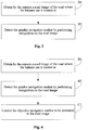
- Fig. 1 is a flowchart illustrating a method for controlling a balance car according to an exemplary embodiment.
- the method includes step S101 to step S102
- a navigation marker (or navigation sign, or objective navigation marker) used for navigating the balance car is detected.
- the navigation marker detected in S101 may comprise a plurality of navigation markers.
- the navigation marker includes one or more of a graphic navigation marker, an audio navigation marker, a video navigation marker and an infrared navigation marker, and is used to indicate at least one of a traveling direction and a traveling speed that the balancer car should comply with or take into account when navigating.
- a navigation marker can be used to obtain navigation instructions for the purpose of controlling navigation of the balance car, such as obtaining instructions related to traveling direction and/or traveling speed.
- the balance car is controlled to travel according to the navigation marker when the navigation marker is detected.
- the balance car By detecting a navigation marker used for navigating the balance car, the balance car can be controlled intelligently to travel according to the navigation marker when the navigation marker is detected, without requiring a user to drive the balance car, so that an intelligent control to the balance car can be realized, the problem that the user needs to drag the balance car manually if he cannot drive the balance car can be avoided, and the user is greatly facilitated.
- the embodiment of the present disclosure provides a method for detecting a navigation marker used for navigating the balance car, which is a further subdivision and extension of the step S101 illustrated in Fig. 1 .
- Fig. 2 is a flowchart illustrating that a navigation marker used for navigating a balance car is detected according to an exemplary embodiment.
- the step S101 illustrated in Fig. 1 is implemented, that is, the navigation marker used for navigating the balance car is detected, through the following steps.
- step A1 a candidate marker on the road where the balance car is located is detected.
- candidate marker it is meant a marker that may be potentially used as a navigation marker to control the balance car.
- the candidate marker can be all kinds of markers (or signs or the like) drawn on the road that may represent the navigation marker, such as various lines and icons.
- step A2 attribute information of the candidate marker is obtained in response to the candidate marker being detected.
- the attribute information is used to represent all kinds of attributes of candidate markers, such as set position, color, length and width.
- the navigation marker is determined according to the attribute information, a similarity between the attribute information of the navigation marker and predetermined attribute information is greater than a predetermined similarity.
- the predetermined attribute information includes standard attribute information of the navigation marker that is previously preset.
- Some interfering objects may be present on the road where the balance car is located, or multiple navigation markers with different attribute information can be provided on the road.
- the candidate marker on the road where the balance car is located can be detected first when the navigation marker is being detected.
- Required navigation marker can be determined from the candidate marker, after the candidate marker is detected.
- detection of a yellow navigation marker is taken as an example.
- the candidate marker on the road where the balance car is located is detected.
- the attribute information of the candidate marker is obtained in response to the candidate marker being detected, that is, the color of the candidate marker is obtained.
- the color similarity between the color of the candidate marker and yellow is obtained, and then the candidate marker with color similarity greater than the predetermined similarity is obtained and determined as the navigation marker.
- the candidate marker whose attribute information has maximum similarity with the predetermined attribute information among the multiple candidate markers can be determined as the navigation marker.
- the navigation marker includes at least one of a graphic navigation marker, an audio navigation marker, a video navigation marker and an infrared navigation marker.
- the navigation marker may indicate at least one of a traveling direction and a traveling speed.
- a navigation marker may thus indicate or provide navigation instruction, such as traveling direction and/or traveling speed that the balance car is to comply with or take into account when navigating.
- the navigation marker includes at least one of above described markers and, thus, is abundant in its types, so that the balance car can travel according to different types of navigation markers. Moreover, the navigation marker can indicate at least one of the traveling direction and the traveling speed, thus the balance car can be controlled intelligently to travel according to indicated traveling direction and indicated traveling speed, and the user is greatly facilitated.
- the traveling speed required by a navigation marker can be low to ensure driving safety. If the traveling speed is lower than or equal to the user's walking speed, the balance car can follow the user and travel automatically according to the navigation marker.
- the embodiment of the present disclosure provides another method for detecting a navigation marker used for navigating the balance car, which is a further subdivision and extension of the step S101 illustrated in Fig. 1 .
- the navigation marker includes a graphic navigation marker
- the balance car is provided with a camera, which can be installed on any place in the balance car, such as on the base of the balance car.
- Fig. 3 is a flowchart illustrating that a navigation marker used for navigating a balance car is detected according to another exemplary embodiment.
- the step S101 illustrated in Fig. 1 is implemented, that is, the navigation marker used for navigating the balance car is detected, through the following steps.
- step B1 a road image of the road where the balance car is located is obtained by the camera.
- step B2 the graphic navigation marker is detected by performing recognition on the road image.
- the navigation marker includes the graphic navigation marker and the balance car is provided with a camera
- the road where the balance car is located can be shot by the camera to obtain the road image when the graphic navigation marker is obtained, and then the road image can be performed recognition, thus the graphic navigation marker on the road can be detected accurately.
- the balance car may be also provided with a lighting device such as a lamp.
- a lighting device such as a lamp.
- the lighting device can be turned on if current ambient brightness is lower than a predetermined ambient brightness, so that the current ambient brightness can be higher than or equal to the predetermined ambient brightness.
- the road image with high resolution and definition can still be shot under low ambient brightness, and it benefits that the road image can be performed recognition better so that the graphic navigation marker can be detected accurately.
- the graphic navigation marker includes at least one of a navigation icon on the road, a navigation icon on a signpost and a navigation icon on a building near the road.
- the graphic navigation marker on the road where the balance car is located can be at least one of a navigation marker drawn on the road, a navigation marker on a signpost near the road (for example both sides of the road) and a navigation marker on a building near the road (for example on the wall of a building along the road).
- the graphic navigation can include a navigation line, a navigation guidance arrow, an icon, characters, and the like.
- the navigation marker includes a navigation icon on the road.
- the navigation icon on the road may be for instance a navigation line on the road.
- the attribute information includes at least one of set position, color, length and width.
- the navigation icon on the road can include a navigation line on the road and the attribute information can include at least one of set position, color, length and width, so that when the navigation marker is determined according to the attribute information, the similarity between the attribute information and the predetermined attribute information can be derived by determining whether the set position is within a preset position, whether the color of the candidate marker is same with a preset color, whether a continuous length of the candidate marker exceeds a preset length, or whether a width of the candidate marker exceeds a preset width, or the like. Then the navigation marker can be determined accurately according to the attribute information of the candidate marker.
- the embodiment of the present disclosure provides a method for controlling the balance car to travel according to a navigation marker, which is a further subdivision and extension of the step S102 illustrated in Fig. 1 .
- the step S102 illustrated in Fig. 1 is implemented, that is, the balance car is controlled to travel according to the navigation marker, through the following steps.
- the balance car is controlled to travel according to the navigation line on the road, which can be navigation lines of various colors drawn in advance, such as white, black, red and the like.
- the balance car When the balance car is controlled to travel according to the navigation marker, if the navigation marker includes a navigation line on the road, the balance car can be controlled intelligently to travel itself according to the navigation line on the road, so that the balance car can be navigated by the navigation line on the road.
- Fig. 4 is a flowchart illustrating that a balance car is controlled to travel according to a navigation marker according to an exemplary embodiment.
- the step S102 illustrated in Fig. 1 is implemented, that is, the balance car is controlled to travel according to the navigation marker, through the following steps.
- step C1 the navigation marker is controlled so that it is kept present (positioned) in the road image.
- the balance car can be controlled to travel according to the navigation marker such that the navigation marker is always present (is maintained) in the road image. Thus the balance car can be ensured to travel automatically without deviating from the navigation marker.
- the navigation marker includes respectively an audio navigation marker, a video navigation marker and an infrared navigation marker
- these navigation markers can be detected for the balance car via a signal sent by a device, which can be a device wired or wireless connected with the balance car and located any place.
- the device may interact with the balance car and send an audio signal including an audio navigation marker, a video signal including a video navigation marker or an infrared signal including an infrared navigation marker to the balance car, so that the audio navigation marker can be detected by performing recognition on the received audio signal, the video navigation marker can be detected by performing recognition on the received video signal, the infrared navigation marker can be detected by performing recognition on the received infrared signal, and then the balance car can travel according to the detected audio navigation marker, the detected video navigation marker, the detected infrared navigation marker.
- the device can be positioned on the road where the balance car is located, and send an infrared signal including an infrared navigation marker or an audio signal including an audio navigation marker to the balance car when the balance car is detected to be approaching, so that recognition can be performed on the infrared signal and audio signal by the balance car, then the infrared navigation marker or the audio navigation marker can be detected, and the balance car can travel according to the infrared navigation marker or the audio navigation marker.
- these makers can be output by means of audio, text or image.
- the graphic navigation marker can also be output by means of displaying an image on a device.
- the embodiment of the present disclosure provides another method for controlling the balance car to travel according to a navigation marker, which is a further subdivision and extension of the step S102 illustrated in Fig. 1 .
- Fig. 5 is a flowchart illustrating that a balance car is controlled to travel according to a navigation marker according to another exemplary embodiment.
- the step S102 illustrated in Fig. 1 is implemented, that is, the balance car is controlled to travel according to the navigation marker, through the following steps.
- step 501 a travelling instruction is obtained according to the navigation marker.
- step 502 the balance car is controlled to travel according to the travelling instruction, which is used to indicate at least one of a traveling direction and a traveling speed of the balancer car.
- a travelling instruction can be obtained according to the navigation marker, and then the balance car can be controlled intelligently to travel automatically according to the travelling instruction.
- the travelling instruction can be obtained by performing graph recognition on the graphic navigation marker.
- the travelling direction can be obtained by performing recognition on the direction where a guidance arrow in the graphic navigation marker is pointed to, and the travelling speed can be obtained by performing recognition on a speed limit sign in the graphic navigation marker.
- the travelling instruction can be obtained by performing audio recognition on the audio navigation marker.
- the travelling direction can be obtained by performing recognition on voice information (for example, the voice information indicative of turning left or turning right) used to indicate a direction in the audio navigation marker by means of voice recognition technology in related art
- the travelling speed can be obtained by performing recognition on voice information (for example, a top speed of the balance car is XX meter per second) used to indicate speed in the audio navigation marker by means of voice recognition technology in related art.
- the travelling instruction can be obtained by performing audio recognition or graph recognition on the video navigation marker.
- the travelling direction can be obtained by performing recognition on voice information or image (for example, characters including a indicated direction or an image including a guidance arrow) used to indicate a direction in the video navigation marker
- the travelling speed can be obtained by performing recognition on voice information or image (for example, an image including speed) used to indicate a speed in the video navigation marker.
- the travelling instruction can be obtained by performing infrared recognition on the infrared navigation marker.
- the travelling direction can be obtained by performing recognition on infrared signals used to indicate a direction in the infrared navigation marker
- the travelling speed can be obtained by performing recognition on infrared signals used to indicate speed in the infrared navigation marker.
- the embodiment of the present disclosure provides another method for controlling the balance car to travel according to a navigation marker, which is a further subdivision and extension of the step S102 illustrated in Fig. 1 .
- Fig. 6 is a flowchart illustrating that a balance car is controlled to travel according to a navigation marker according to still another exemplary embodiment.
- the step S102 illustrated in Fig. 1 is implemented, that is, the balance car is controlled to travel according to the navigation marker when the navigation marker is detected, through the following steps.
- a final navigation marker can be determined by at least one of the following selection manners of a navigation line.
- the crossing can be any crossing on the road where the balance car is located.
- step S602 the balance car is controlled to travel according to the final navigation marker.
- the selection of the navigation line include following manners.
- the final navigation marker can be determined according to a preset travelling direction corresponding to the crossing, which may be a travelling direction that is preset according to a travelling destination of the balance car.
- the navigation marker indicating the travelling direction can be determined as the final navigation marker. Then the balance car can be controlled to travel automatically according to the navigation marker including this travelling direction.
- a selection instruction of travelling direction is received, and the final navigation marker is determined according to the selection instruction of travelling direction.
- the navigation marker that the user expects (that is, the navigation marker selected according to the selection instruction of travelling direction) can be selected as the final navigation marker according to the selection instruction of travelling direction. Then, the balance car can be navigated by the navigation marker selected by the selection instruction of travelling direction, and travel automatically according to the travelling direction and travelling speed that the user expects.
- the final navigation marker can be determined according to the historic selected record of the navigation line.
- the balance car can be controlled to travel automatically according to the most commonly used navigation marker or the most recently used navigation marker.
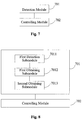
- Fig. 7 is a block diagram illustrating an apparatus for controlling a balance car according to an exemplary embodiment.
- the apparatus includes:
- the present disclosure provides a detection module which is a further subdivision and extension of the detection module illustrated in Fig. 7 .
- Fig. 8 is a block diagram illustrating a detecting module according to an exemplary embodiment.
- the detection module 701 includes:
- the navigation marker includes at least one of a graphic navigation marker, an audio navigation marker, a video navigation marker and an infrared navigation marker.
- the navigation marker may indicate at least one of a traveling direction and a traveling speed.
- the present disclosure provides another detection module which is a further subdivision and extension of the detection module illustrated in Fig. 7 .
- Fig. 9 is a block diagram illustrating another detecting module according to an exemplary embodiment.
- the navigation marker includes the graphic navigation marker, and the balance car is provided with a camera.
- the detection module 701 illustrated Fig. 7 includes:
- the graphic navigation marker may include at least one of a navigation icon on the road, a navigation icon on a signpost and a navigation icon on a building near the road.
- the navigation marker may include at least one of a navigation icon on a road, the navigation icon on the road includes a navigation line on the road.
- the attribute information may include at least one of set position, color, length and width.
- the present disclosure provides a controlling module which is a further subdivision and extension of the controlling module illustrated in Fig. 9 .
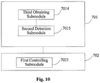
- Fig. 10 is a block diagram illustrating a controlling module according to an exemplary embodiment.
- the controlling module illustrated 702 in Fig. 9 includes:
- the present disclosure provides another controlling module which is a further subdivision and extension of the controlling module illustrated in Fig. 9 .
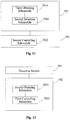
- Fig. 11 is a block diagram illustrating another controlling module according to an exemplary embodiment.
- the controlling module illustrated 702 in Fig. 9 includes:
- the present disclosure provides another controlling module which is a further subdivision and extension of the controlling module illustrated in Fig. 9 .
- Fig. 12 is a block diagram illustrating still another controlling module according to an exemplary embodiment.
- the controlling module illustrated 702 in Fig. 9 includes:
- the present disclosure provides another controlling module which is a further subdivision and extension of the controlling module illustrated in Fig. 9 .
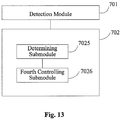
- Fig. 13 is a block diagram illustrating yet still another controlling module according to an exemplary embodiment.
- the controlling module 702 illustrated in Fig. 9 includes:
- the selection of the navigation line may include following manners.
- the final navigation marker may be determined according to a preset travelling direction corresponding to the crossing.
- a selection instruction of travelling direction may be received, and the final navigation marker can be determined according to the selection instruction of travelling direction.
- the final navigation marker can be determined according to the historic selected record of the navigation line.
- an apparatus for controlling a balance car includes:
- the above described processor configured to detect an navigation marker used for navigating the balance car is further configured to:
- the navigation marker includes at least one of a graphic navigation marker, an audio navigation marker, a video navigation marker and an infrared navigation marker; and the navigation marker indicates at least one of a traveling direction and a traveling speed.
- the navigation marker includes the graphic navigation marker
- the balance car is provided with a camera
- the processor configured to the detect a navigation marker used for navigating the balance car is further configured to:
- the above described processor is also configured to: the graphic navigation marker includes at least one of a navigation icon on the road, a navigation icon on a signpost and a navigation icon on a building near the road.
- the navigation marker includes the navigation icon on the road, the navigation icon on the road including a navigation line on the road; and the attribute information includes at least one of set position, color, length and width.
- the above described processor configured to control the balance car to travel according to the navigation marker is further configured to:
- the above described processor configured to control the balance car to travel according to the navigation marker is further configured to:
- the above described processor configured to control the balance car to travel according to the navigation marker is further configured to:
- the above described processor configured to control the balance car to travel according to the navigation marker, when the navigation marker is detected, is further configured to:
- the selection of the navigation line may include following manners.
- the final navigation marker may be determined according to a preset travelling direction corresponding to the crossing.
- a selection instruction of travelling direction is received, and the final navigation marker can be determined according to the selection instruction of travelling direction.
- the final navigation marker can be determined according to the historic selected record of the navigation line.
- Fig. 14 is a block diagram showing an apparatus 1400 for controlling a balance car according to an exemplary embodiment, which can be used in a terminal equipment.
- the apparatus 1400 may be a mobile phone, a computer, a digital broadcast terminal, a message transceiver device, a game console, a tablet device, a medical equipment, a fitness equipment, a personal digital assistant, and the like.
- the apparatus 1400 may include one or more of the following components: a processing component 1402, a memory 1404, a power component 1406, a multimedia component 1408, an audio component 1410, an input/output (I/O) interface 1412, a sensor component 1414, and a communication component 1416.
- a processing component 1402 a memory 1404, a power component 1406, a multimedia component 1408, an audio component 1410, an input/output (I/O) interface 1412, a sensor component 1414, and a communication component 1416.
- the processing component 1402 typically controls overall operations of the apparatus 1400, such as the operations associated with display, telephone calls, data communications, camera operations, and recording operations.
- the processing component 1402 may include one or more processors 1420 to execute instructions to perform all or part of the steps in the above described methods.
- the processing component 1402 may include one or at least two modules which facilitate the interaction between the processing component 1402 and other components.
- the processing component 1402 may include a multimedia module to facilitate the interaction between the multimedia component 1408 and the processing component 1402.
- the memory 1404 is configured to store various types of data to support the operation of the apparatus 1400. Examples of such data include instructions for any applications or methods operated on the apparatus 1400, contact data, phonebook data, messages, pictures, video, etc.
- the memory 1404 may be implemented using any type of volatile or non-volatile memory devices, or a combination thereof, such as a static random access memory (SRAM), an electrically erasable programmable read-only memory (EEPROM), an erasable programmable read-only memory (EPROM), a programmable read-only memory (PROM), a read-only memory (ROM), a magnetic memory, a flash memory, a magnetic or optical disk.
- SRAM static random access memory
- EEPROM electrically erasable programmable read-only memory
- EPROM erasable programmable read-only memory
- PROM programmable read-only memory
- ROM read-only memory
- magnetic memory a magnetic memory
- flash memory a flash memory
- magnetic or optical disk a magnetic
- the power component 1406 provides power to various components of the apparatus 1400.
- the power component 1406 may include a power management system, one or at least two power sources, and any other components associated with the generation, management, and distribution of power in the apparatus 1400.
- the multimedia component 1408 includes a screen providing an output interface between the apparatus 1400 and the user.
- the screen may include a liquid crystal display (LCD) and a touch panel (TP). If the screen includes the touch panel, the screen may be implemented as a touch screen to receive input signals from the user.
- the touch panel includes one or more touch sensors to sense touches, slips, and gestures on the touch panel. The touch sensors may not only sense a boundary of a touch or slip action, but also sense a period of time and a pressure associated with the touch or slip action.
- the multimedia component 1408 includes a front camera and/or a rear camera. The front camera and the rear camera may receive an external multimedia datum while the apparatus 1400 is in an operation mode, such as a photographing mode or a video mode. Each of the front camera and the rear camera may be a fixed optical lens system or have focus and optical zoom capability.
- the audio component 1410 is configured to output and/or input audio signals.
- the audio component 1410 includes a microphone ("MIC") configured to receive an external audio signal when the apparatus 1400 is in an operation mode, such as a call mode, a recording mode, and a voice recognition mode.
- the received audio signal may be further stored in the memory 1404 or transmitted via the communication component 1416.
- the audio component 1410 further includes a speaker to output audio signals.
- the I/O interface 1412 provides an interface between the processing component 802 and peripheral interface modules, such as a keyboard, a click wheel, buttons, and the like.
- the buttons may include, but are not limited to, a home button, a volume button, a starting button, and a locking button.
- the sensor component 1414 includes one or at least two sensors to provide status assessments of various aspects of the apparatus 1400. For instance, the sensor component 1414 may detect an open/closed status of the apparatus 1400, relative positioning of components, e.g., the display and the keypad, of the apparatus 1400, a change in position of the apparatus 1400 or a component of the apparatus 1400, a presence or absence of user contact with the apparatus 1400, an orientation or an acceleration/deceleration of the apparatus 1400, and a change in temperature of the apparatus 1400.
- the sensor component 1414 may include a proximity sensor configured to detect the presence of nearby objects without any physical contact.
- the sensor component 1414 may also include a light sensor, such as a CMOS or CCD image sensor, for use in imaging applications.
- the sensor component 1414 may also include an accelerometer sensor, a gyroscope sensor, a magnetic sensor, a pressure sensor, or a temperature sensor.
- the communication component 1416 is configured to facilitate communication, wired or wirelessly, between the apparatus 1400 and other devices.
- the apparatus 1400 can access a wireless network based on a communication standard, such as WiFi, 2G, or 3G, or a combination thereof.
- the communication component 1416 receives a broadcast signal or broadcast associated information from an external broadcast management system via a broadcast channel.
- the communication component 1416 further includes a near field communication (NFC) module to facilitate short-range communications.
- the NFC module may be implemented based on a radio frequency identification (RFID) technology, an infrared data association (IrDA) technology, an ultra-wideband (UWB) technology, a Bluetooth (BT) technology, and other technologies.
- RFID radio frequency identification
- IrDA infrared data association
- UWB ultra-wideband
- BT Bluetooth
- the apparatus 1400 may be implemented with one or more application specific integrated circuits (ASICs), digital signal processors (DSPs), digital signal processing devices (DSPDs), programmable logic devices (PLDs), field programmable gate arrays (FPGAs), controllers, micro-controllers, microprocessors, or other electronic components, for performing the above described methods.
- ASICs application specific integrated circuits
- DSPs digital signal processors
- DSPDs digital signal processing devices
- PLDs programmable logic devices
- FPGAs field programmable gate arrays
- controllers micro-controllers, microprocessors, or other electronic components, for performing the above described methods.
- non-transitory computer-readable storage medium including instructions, such as included in the memory 1404, executable by the processor 1420 in the apparatus 1400, for performing the above-described methods.
- the non-transitory computer-readable storage medium may be a ROM, a RAM, a CD-ROM, a magnetic tape, a floppy disc, an optical data storage device, and the like.
- a non-transitory computer readable storage medium when instructions in the storage medium are executed by a processor of the apparatus 1400, the apparatus 1400 is enabled to perform a method for controlling a balance car, including:
- the detecting a navigation marker used for navigating the balance car includes:
- the navigation marker includes at least one of a graphic navigation marker, an audio navigation marker, a video navigation marker and an infrared navigation marker; and the navigation marker indicates at least one of a traveling direction and a traveling speed.
- the navigation marker includes the graphic navigation marker
- the balance car is provided with a camera
- the detecting a navigation marker used for navigating the balance car includes:
- the graphic navigation marker includes at least one of a navigation icon on the road, a navigation icon on a signpost and a navigation icon on a building near the road.
- the navigation marker includes the navigation icon on the road, the navigation icon on the road including a navigation line on the road; and the attribute information includes at least one of set position, color, length and width.
- controlling the balance car to travel according to the navigation marker includes:
- the controlling the balance car to travel according to the navigation marker includes:
- controlling the balance car to travel according to the navigation marker includes:
- controlling the balance car to travel according to the navigation marker when the navigation marker is detected includes:
- the selection of the navigation line may include following manners:
- modules are referred to in apparatus embodiments for carrying out various steps of the described method(s) it will be understood that these modules may be implemented in hardware, in software, or a combination of the two.
- the modules When implemented in hardware, the modules may be implemented as one or more hardware modules, such as one or more application specific integrated circuits.
- the modules When implemented in software, the modules may be implemented as one or more computer programs that are executed on one or more processors.
Landscapes
- Engineering & Computer Science (AREA)
- Radar, Positioning & Navigation (AREA)
- Remote Sensing (AREA)
- Physics & Mathematics (AREA)
- General Physics & Mathematics (AREA)
- Automation & Control Theory (AREA)
- Aviation & Aerospace Engineering (AREA)
- Mechanical Engineering (AREA)
- Electromagnetism (AREA)
- Computer Vision & Pattern Recognition (AREA)
- Multimedia (AREA)
- Acoustics & Sound (AREA)
- Theoretical Computer Science (AREA)
- Navigation (AREA)
- Traffic Control Systems (AREA)
- Control Of Position, Course, Altitude, Or Attitude Of Moving Bodies (AREA)
Abstract
Description
- The present disclosure relates to the field of balance car technology and, particularly, to a method and an apparatus for controlling a balance car.
- Currently, more users are using a balance car instead of walk. However, driving the balance car is not allowable in some areas for the sake of safety, so a user may need to drag the balance car manually if he wants to move it to a place in these areas, which brings a great trouble to the user's operation and requires a lot of physical strength.
- A method and an apparatus for controlling a balance car are provided by particular embodiments of the present disclosure. The technical solutions are as follows.
- According to a first aspect of the embodiments of the present disclosure, a method for controlling a balance car is provided. The method includes:
- detecting a navigation marker used for navigating the balance car; and
- controlling the balance car to travel according to the navigation marker when the navigation marker is detected.
- In an embodiment, the detecting a navigation marker used for navigating the balance car includes:
- detecting a candidate marker on a road where the balance car is located;
- obtaining attribute information of the candidate marker in response to the candidate marker being detected; and
- determining the navigation marker according to the attribute information, wherein a similarity between the attribute information of the navigation marker and predetermined attribute information is greater than a predetermined similarity.
- In an embodiment, the navigation marker includes at least one of a graphic navigation marker, an audio navigation marker, a video navigation marker and an infrared navigation marker; and
the navigation marker indicates at least one of a traveling direction and a traveling speed. - In an embodiment, the navigation marker includes the graphic navigation marker, the balance car is provided with a camera; and
the detecting a navigation marker used for navigating the balance car includes: - obtaining by the camera a road image of the road where the balance car is located; and
- detecting the graphic navigation marker by performing recognition on the road image.
- In an embodiment, the graphic navigation marker includes at least one of a navigation icon on the road, a navigation icon on a signpost and a navigation icon on a building near the road.
- In an embodiment, the navigation marker includes the navigation icon on the road, the navigation icon on the road including a navigation line on the road; and
the attribute information includes at least one of set position, color, length and width. - In an embodiment, the controlling the balance car to travel according to the navigation marker includes:
- controlling the balance car to travel along the navigation line on the road.
- In an embodiment, the controlling the balance car to travel according to the navigation marker includes:
- controlling the navigation marker to be present in the road image.
- In an embodiment, the controlling the balance car to travel according to the navigation marker includes:
- obtaining a travelling instruction according to the navigation marker; and
- controlling the balance car to travel according to the travelling instruction.
- In a particular embodiment, the steps of the method for controlling a balance car are determined by computer program instructions.
- Consequently, according to a particular embodiment, the invention is also directed to a computer program for executing the steps of a method for controlling a balance car as defined above when this program is executed by a computer.
- This program can use any programming language and take the form of source code, object code or a code intermediate between source code and object code, such as a partially compiled form, or any other desirable form.
- The invention is also directed to a computer-readable information medium containing instructions of a computer program as defined above.
- The information medium can be any entity or device capable of storing the program. For example, the support can include storage means such as a ROM, for example a CD ROM or a microelectronic circuit ROM, or magnetic storage means, for example a diskette (floppy disk) or a hard disk.
- Alternatively, the information medium can be an integrated circuit in which the program is incorporated, the circuit being adapted to execute the method in question or to be used in its execution.
- According to a second aspect of the embodiments of the present disclosure, an apparatus for controlling a balance car is provided. The apparatus includes:
- a detection module configured to detect a navigation marker used for navigating the balance car; and
- a controlling module configured to control the balance car to travel according to the navigation marker when the navigation marker is detected by the detection module.
- In an embodiment, the detection module includes:
- a first detection sub-module configured to detect a candidate marker on a road where the balance car is located;
- a first obtaining sub-module configured to obtain attribute information of the candidate marker in response to the candidate marker being detected by the first detection sub-module; and
- a second obtaining sub-module configured to obtain the navigation marker according to the attribute information obtained by the first obtaining sub-module, wherein a similarity between the attribute information of the navigation marker and predetermined attribute information is greater than a predetermined similarity.
- In an embodiment, the navigation marker includes at least one of a graphic navigation marker, an audio navigation marker, a video navigation marker and an infrared navigation marker; and
the navigation marker indicates at least one of a traveling direction and a traveling speed. - In an embodiment, the navigation marker includes the graphic navigation marker, the balance car is provided with a camera; and
the detection module includes: - a third obtaining sub-module configured to obtain by the camera a road image of the road where the balance car is located; and
- a second detection sub-module configured to detect the graphic navigation marker by performing recognition on the road image obtained by the third obtaining sub-module.
- In an embodiment, the graphic navigation marker includes at least one of a navigation icon on the road, a navigation icon on a signpost and a navigation icon on a building near the road.
- In an embodiment, the navigation marker includes the navigation icon on the road, the navigation icon on the road including a navigation line on the road;
the attribute information includes at least one of set position, color, length and width. - In an embodiment, the controlling module includes:
- a first controlling sub-module configured to control the balance car to travel along the navigation line on the road.
- In an embodiment, the controlling module includes:
- a second controlling sub-module configured to control the navigation marker to be present in the road image obtained by the third obtaining sub-module.
- In an embodiment, the controlling module includes:
- a fourth obtaining sub-module configured to obtain a travelling instruction according to the navigation marker detected by the detection module; and
- a third controlling sub-module configured to control the balance car to travel according to the travelling instruction obtained by the fourth obtaining sub-module.
- According to a third aspect of the embodiments of the present disclosure, an apparatus for controlling a balance car is provided. The apparatus includes:
- a processor; and
- a memory configured to store an instruction executable by the processor;
- detect an navigation marker used for navigating the balance car; and
- control the balance car to travel according to the navigation marker when the navigation marker is detected.
- The technical solutions provided by the embodiments of the present disclosure may achieve the following advantageous effects.
- According to the technical solutions provided by the embodiments of the present disclosure, by detecting a navigation marker used for navigating the balance car, the balance car can be controlled intelligently to travel according to the navigation marker when the navigation marker is detected, without requiring a user to drive the balance car, so that an intelligent control to the balance car can be realized, the problem that the user needs to drag the balance car manually if he cannot drive the balance car can be avoided, and the user is greatly facilitated.
- It should be understood that the above general description and the detailed description below are merely exemplary, and do not limit the present disclosure.
- The accompanying drawings are incorporated in and constitute a part of this specification, illustrate embodiments conforming to the disclosure and together with the description serve to explain the principles of the disclosure.
-
FIG. 1 is a flowchart illustrating a method for controlling a balance car according to an exemplary embodiment. -
FIG. 2 is a flowchart illustrating that a navigation marker used for navigating a balance car is detected according to an exemplary embodiment. -
FIG. 3 is a flowchart illustrating that a navigation marker used for navigating a balance car is detected according to another exemplary embodiment. -
FIG. 4 is a flowchart illustrating that a balance car is controlled to travel according to a navigation marker according to an exemplary embodiment. -
FIG. 5 is a flowchart illustrating that a balance car is controlled to travel according to a navigation marker according to another exemplary embodiment. -
FIG. 6 is a flowchart illustrating that a balance car is controlled to travel according to a navigation marker according to still another exemplary embodiment. -
FIG. 7 is a block diagram illustrating an apparatus for controlling a balance car according to an exemplary embodiment. -
FIG. 8 is a block diagram illustrating a detecting module according to an exemplary embodiment. -
FIG. 9 is a block diagram illustrating a detecting module according to another exemplary embodiment. -
FIG. 10 is a block diagram illustrating a controlling module according to an exemplary embodiment. -
FIG. 11 is a block diagram illustrating a controlling module according to another exemplary embodiment. -
FIG. 12 is a block diagram illustrating a controlling module according to still another exemplary embodiment. -
FIG. 13 is a block diagram illustrating a controlling module according to still yet another exemplary embodiment. -
FIG. 14 is a block diagram illustrating a controlling apparatus applied to a balance car according to an exemplary embodiment. - Descriptions will now be made in detail to exemplary embodiments, examples of which are illustrated in the accompanying drawings. When accompanying figures are mentioned in the following descriptions, the same numbers in different drawings represent the same or similar elements, unless otherwise represented. The implementations set forth in the following description of exemplary embodiments do not represent all implementations consistent with the invention. Instead, they are merely examples of apparatus and methods consistent with aspects related to the disclosure as recited in the appended claims.
- Currently, more users are using a balance car instead of walk. However, driving the balance car is not allowable in some areas for the sake of safety, so a user may need to drag the balance car manually if he wants to move it to a place in these areas, which brings a great trouble to the user's operation and requires a lot of physical strength.
- In order to overcome those problems described above, embodiments of the present disclosure provide a method for controlling a balancer car. The method can be used in a procedure, a system or an apparatus for controlling the balancer car, while an execution body implementing the method may be a balancer car or a terminal connected with the balancer car.
- The embodiment of the present disclosure provides a method for controlling a balancer car. Referring to
Fig. 1, Fig. 1 is a flowchart illustrating a method for controlling a balance car according to an exemplary embodiment. - As shown in
Fig. 1 , the method includes step S101 to step S102 - In the step S101, a navigation marker (or navigation sign, or objective navigation marker) used for navigating the balance car is detected. In a particular example, the navigation marker detected in S101 may comprise a plurality of navigation markers.
- In an embodiment, the navigation marker includes one or more of a graphic navigation marker, an audio navigation marker, a video navigation marker and an infrared navigation marker, and is used to indicate at least one of a traveling direction and a traveling speed that the balancer car should comply with or take into account when navigating. A navigation marker can be used to obtain navigation instructions for the purpose of controlling navigation of the balance car, such as obtaining instructions related to traveling direction and/or traveling speed.
- In the step S102, the balance car is controlled to travel according to the navigation marker when the navigation marker is detected.
- By detecting a navigation marker used for navigating the balance car, the balance car can be controlled intelligently to travel according to the navigation marker when the navigation marker is detected, without requiring a user to drive the balance car, so that an intelligent control to the balance car can be realized, the problem that the user needs to drag the balance car manually if he cannot drive the balance car can be avoided, and the user is greatly facilitated.
- The embodiment of the present disclosure provides a method for detecting a navigation marker used for navigating the balance car, which is a further subdivision and extension of the step S101 illustrated in
Fig. 1 . - Referring to
Fig. 2, Fig. 2 is a flowchart illustrating that a navigation marker used for navigating a balance car is detected according to an exemplary embodiment. - As shown in
Fig. 2 , the step S101 illustrated inFig. 1 is implemented, that is, the navigation marker used for navigating the balance car is detected, through the following steps. - In step A1, a candidate marker on the road where the balance car is located is detected. By "candidate marker", it is meant a marker that may be potentially used as a navigation marker to control the balance car.
- The candidate marker can be all kinds of markers (or signs or the like) drawn on the road that may represent the navigation marker, such as various lines and icons.
- In step A2, attribute information of the candidate marker is obtained in response to the candidate marker being detected.
- The attribute information is used to represent all kinds of attributes of candidate markers, such as set position, color, length and width.
- In step A3, the navigation marker is determined according to the attribute information, a similarity between the attribute information of the navigation marker and predetermined attribute information is greater than a predetermined similarity. In an embodiment, the predetermined attribute information includes standard attribute information of the navigation marker that is previously preset.
- Some interfering objects may be present on the road where the balance car is located, or multiple navigation markers with different attribute information can be provided on the road. Thus, the candidate marker on the road where the balance car is located can be detected first when the navigation marker is being detected. Required navigation marker can be determined from the candidate marker, after the candidate marker is detected.
- For instance, detection of a yellow navigation marker is taken as an example. The candidate marker on the road where the balance car is located is detected. The attribute information of the candidate marker is obtained in response to the candidate marker being detected, that is, the color of the candidate marker is obtained. The color similarity between the color of the candidate marker and yellow is obtained, and then the candidate marker with color similarity greater than the predetermined similarity is obtained and determined as the navigation marker.
- Moreover, if there are multiple candidate markers, the similarity between whose attribute information and the predetermined attribute information is greater than the predetermined similarity, the candidate marker whose attribute information has maximum similarity with the predetermined attribute information among the multiple candidate markers can be determined as the navigation marker.
- In an embodiment, the navigation marker includes at least one of a graphic navigation marker, an audio navigation marker, a video navigation marker and an infrared navigation marker.
- The navigation marker may indicate at least one of a traveling direction and a traveling speed. A navigation marker may thus indicate or provide navigation instruction, such as traveling direction and/or traveling speed that the balance car is to comply with or take into account when navigating.
- The navigation marker includes at least one of above described markers and, thus, is abundant in its types, so that the balance car can travel according to different types of navigation markers. Moreover, the navigation marker can indicate at least one of the traveling direction and the traveling speed, thus the balance car can be controlled intelligently to travel according to indicated traveling direction and indicated traveling speed, and the user is greatly facilitated.
- Moreover, the traveling speed required by a navigation marker can be low to ensure driving safety. If the traveling speed is lower than or equal to the user's walking speed, the balance car can follow the user and travel automatically according to the navigation marker.
- The embodiment of the present disclosure provides another method for detecting a navigation marker used for navigating the balance car, which is a further subdivision and extension of the step S101 illustrated in
Fig. 1 . In the method, the navigation marker includes a graphic navigation marker, and the balance car is provided with a camera, which can be installed on any place in the balance car, such as on the base of the balance car. - Referring to
Fig. 3, Fig. 3 is a flowchart illustrating that a navigation marker used for navigating a balance car is detected according to another exemplary embodiment. - As shown in
Fig. 3 , the step S101 illustrated inFig. 1 is implemented, that is, the navigation marker used for navigating the balance car is detected, through the following steps. - In step B1, a road image of the road where the balance car is located is obtained by the camera.
- In step B2, the graphic navigation marker is detected by performing recognition on the road image.
- If the navigation marker includes the graphic navigation marker and the balance car is provided with a camera, the road where the balance car is located can be shot by the camera to obtain the road image when the graphic navigation marker is obtained, and then the road image can be performed recognition, thus the graphic navigation marker on the road can be detected accurately.
- Moreover, the balance car may be also provided with a lighting device such as a lamp. When the road image is obtained, the lighting device can be turned on if current ambient brightness is lower than a predetermined ambient brightness, so that the current ambient brightness can be higher than or equal to the predetermined ambient brightness. Thus the road image with high resolution and definition can still be shot under low ambient brightness, and it benefits that the road image can be performed recognition better so that the graphic navigation marker can be detected accurately.
- In an embodiment, the graphic navigation marker includes at least one of a navigation icon on the road, a navigation icon on a signpost and a navigation icon on a building near the road.
- The graphic navigation marker on the road where the balance car is located can be at least one of a navigation marker drawn on the road, a navigation marker on a signpost near the road (for example both sides of the road) and a navigation marker on a building near the road (for example on the wall of a building along the road). The graphic navigation can include a navigation line, a navigation guidance arrow, an icon, characters, and the like.
- In an embodiment, the navigation marker includes a navigation icon on the road. The navigation icon on the road may be for instance a navigation line on the road.
- The attribute information includes at least one of set position, color, length and width.
- The navigation icon on the road can include a navigation line on the road and the attribute information can include at least one of set position, color, length and width, so that when the navigation marker is determined according to the attribute information, the similarity between the attribute information and the predetermined attribute information can be derived by determining whether the set position is within a preset position, whether the color of the candidate marker is same with a preset color, whether a continuous length of the candidate marker exceeds a preset length, or whether a width of the candidate marker exceeds a preset width, or the like. Then the navigation marker can be determined accurately according to the attribute information of the candidate marker.
- The embodiment of the present disclosure provides a method for controlling the balance car to travel according to a navigation marker, which is a further subdivision and extension of the step S102 illustrated in
Fig. 1 . - The step S102 illustrated in
Fig. 1 is implemented, that is, the balance car is controlled to travel according to the navigation marker, through the following steps. - The balance car is controlled to travel according to the navigation line on the road, which can be navigation lines of various colors drawn in advance, such as white, black, red and the like.
- When the balance car is controlled to travel according to the navigation marker, if the navigation marker includes a navigation line on the road, the balance car can be controlled intelligently to travel itself according to the navigation line on the road, so that the balance car can be navigated by the navigation line on the road.
- Referring to
Fig. 4, Fig. 4 is a flowchart illustrating that a balance car is controlled to travel according to a navigation marker according to an exemplary embodiment. - As shown in
Fig. 4 , in an embodiment, the step S102 illustrated inFig. 1 is implemented, that is, the balance car is controlled to travel according to the navigation marker, through the following steps. - In step C1, the navigation marker is controlled so that it is kept present (positioned) in the road image.
- The balance car can be controlled to travel according to the navigation marker such that the navigation marker is always present (is maintained) in the road image. Thus the balance car can be ensured to travel automatically without deviating from the navigation marker.
- Moreover, when it is controlled such that the navigation marker is always present in the road image, it had better been controlled such that the navigation marker is always present (positioned) in the middle of the road image, thus the balance car can be sufficiently ensured to travel without deviating from the navigation marker
- In an embodiment, if the navigation marker includes respectively an audio navigation marker, a video navigation marker and an infrared navigation marker, these navigation markers can be detected for the balance car via a signal sent by a device, which can be a device wired or wireless connected with the balance car and located any place. The device may interact with the balance car and send an audio signal including an audio navigation marker, a video signal including a video navigation marker or an infrared signal including an infrared navigation marker to the balance car, so that the audio navigation marker can be detected by performing recognition on the received audio signal, the video navigation marker can be detected by performing recognition on the received video signal, the infrared navigation marker can be detected by performing recognition on the received infrared signal, and then the balance car can travel according to the detected audio navigation marker, the detected video navigation marker, the detected infrared navigation marker. For instance, the device can be positioned on the road where the balance car is located, and send an infrared signal including an infrared navigation marker or an audio signal including an audio navigation marker to the balance car when the balance car is detected to be approaching, so that recognition can be performed on the infrared signal and audio signal by the balance car, then the infrared navigation marker or the audio navigation marker can be detected, and the balance car can travel according to the infrared navigation marker or the audio navigation marker.
- To allow the user to learn about these markers, these makers can be output by means of audio, text or image.
- In an embodiment, the graphic navigation marker can also be output by means of displaying an image on a device.
- The embodiment of the present disclosure provides another method for controlling the balance car to travel according to a navigation marker, which is a further subdivision and extension of the step S102 illustrated in
Fig. 1 . - Referring to
Fig. 5, Fig. 5 is a flowchart illustrating that a balance car is controlled to travel according to a navigation marker according to another exemplary embodiment. - As shown in
Fig. 5 , the step S102 illustrated inFig. 1 is implemented, that is, the balance car is controlled to travel according to the navigation marker, through the following steps. - In step 501, a travelling instruction is obtained according to the navigation marker.
- In
step 502, the balance car is controlled to travel according to the travelling instruction, which is used to indicate at least one of a traveling direction and a traveling speed of the balancer car. - When the balance car is controlled to travel according to the navigation marker, a travelling instruction can be obtained according to the navigation marker, and then the balance car can be controlled intelligently to travel automatically according to the travelling instruction.
- In an embodiment, a detailed process for obtaining the travelling instruction is described as follows.
- When the navigation marker includes a graphic navigation marker, the travelling instruction can be obtained by performing graph recognition on the graphic navigation marker. For instance, the travelling direction can be obtained by performing recognition on the direction where a guidance arrow in the graphic navigation marker is pointed to, and the travelling speed can be obtained by performing recognition on a speed limit sign in the graphic navigation marker.
- When the navigation marker includes an audio navigation marker, the travelling instruction can be obtained by performing audio recognition on the audio navigation marker. For instance, the travelling direction can be obtained by performing recognition on voice information (for example, the voice information indicative of turning left or turning right) used to indicate a direction in the audio navigation marker by means of voice recognition technology in related art, and the travelling speed can be obtained by performing recognition on voice information (for example, a top speed of the balance car is XX meter per second) used to indicate speed in the audio navigation marker by means of voice recognition technology in related art.
- When the navigation marker includes a video navigation marker, the travelling instruction can be obtained by performing audio recognition or graph recognition on the video navigation marker. For instance, the travelling direction can be obtained by performing recognition on voice information or image (for example, characters including a indicated direction or an image including a guidance arrow) used to indicate a direction in the video navigation marker, and the travelling speed can be obtained by performing recognition on voice information or image (for example, an image including speed) used to indicate a speed in the video navigation marker.
- When the navigation marker includes an infrared navigation marker, the travelling instruction can be obtained by performing infrared recognition on the infrared navigation marker. For instance, the travelling direction can be obtained by performing recognition on infrared signals used to indicate a direction in the infrared navigation marker, and the travelling speed can be obtained by performing recognition on infrared signals used to indicate speed in the infrared navigation marker.
- The embodiment of the present disclosure provides another method for controlling the balance car to travel according to a navigation marker, which is a further subdivision and extension of the step S102 illustrated in
Fig. 1 . - Referring to
Fig. 6, Fig. 6 is a flowchart illustrating that a balance car is controlled to travel according to a navigation marker according to still another exemplary embodiment. - As shown in
Fig. 6 , the step S102 illustrated inFig. 1 is implemented, that is, the balance car is controlled to travel according to the navigation marker when the navigation marker is detected, through the following steps. - In step S601, when the balance car travels to a crossing and there are at least two navigation markers at the crossing, a final navigation marker can be determined by at least one of the following selection manners of a navigation line. Herein, the crossing can be any crossing on the road where the balance car is located.
- In step S602, the balance car is controlled to travel according to the final navigation marker.
- The selection of the navigation line include following manners.
- The final navigation marker can be determined according to a preset travelling direction corresponding to the crossing, which may be a travelling direction that is preset according to a travelling destination of the balance car.
- When there are multiple navigation markers at the crossing, in order that the final navigation marker can be determined accurately, according to the travelling direction corresponding to the crossing, the navigation marker indicating the travelling direction can be determined as the final navigation marker. Then the balance car can be controlled to travel automatically according to the navigation marker including this travelling direction.
- Alternatively, a selection instruction of travelling direction is received, and the final navigation marker is determined according to the selection instruction of travelling direction.
- When there are multiple navigation markers at the crossing, the navigation marker that the user expects (that is, the navigation marker selected according to the selection instruction of travelling direction) can be selected as the final navigation marker according to the selection instruction of travelling direction. Then, the balance car can be navigated by the navigation marker selected by the selection instruction of travelling direction, and travel automatically according to the travelling direction and travelling speed that the user expects.
- Alternatively, it is determined that whether there is a prestored historic selected record of a navigation line corresponding to the crossing.
- When there is a prestored historic selected record of a navigation line, the final navigation marker can be determined according to the historic selected record of the navigation line.
- When there are multiple navigation markers at the crossing, in order that the final navigation marker can be determined accurately, it is determined that whether there is a prestored historic selected record of a navigation line corresponding to the crossing. If yes, according to the historic selected record of a navigation line, the historic navigation marker which is used most frequently, used greatest number of times or most recently used can be determined as the final navigation marker. Then the balance car can be controlled to travel automatically according to the most commonly used navigation marker or the most recently used navigation marker.
- Moreover, the above embodiments can be implemented individually or in combination.
- Corresponding to the methods for controlling a balance car disclosed in the above described embodiments, the present disclosure also provides an apparatus for controlling a balance car. Referring to
Fig. 7, Fig. 7 is a block diagram illustrating an apparatus for controlling a balance car according to an exemplary embodiment. - As shown in
Fig. 7 , the apparatus includes: - a
detection module 701 configured to detect a navigation marker used for navigating the balance car; and - a controlling
module 702 configured to control the balance car to travel according to the navigation marker when the navigation marker is detected by thedetection module 701. - The present disclosure provides a detection module which is a further subdivision and extension of the detection module illustrated in
Fig. 7 . - Referring to
Fig. 8, Fig. 8 is a block diagram illustrating a detecting module according to an exemplary embodiment. - As shown in
Fig. 8 , thedetection module 701 includes: - a
first detection sub-module 7011 configured to detect a candidate marker on a road where the balance car is located; - a first obtaining sub-module 7012 configured to obtain attribute information of the candidate marker in response to the candidate marker being detected by the
first detection sub-module 7011; and - a second obtaining sub-module 7013 configured to obtain the navigation marker according to the attribute information obtained by the first obtaining sub-module 7012, wherein a similarity between the attribute information of the navigation marker and predetermined attribute information is greater than a predetermined similarity.
- In an embodiment, the navigation marker includes at least one of a graphic navigation marker, an audio navigation marker, a video navigation marker and an infrared navigation marker.
- The navigation marker may indicate at least one of a traveling direction and a traveling speed.
- The present disclosure provides another detection module which is a further subdivision and extension of the detection module illustrated in
Fig. 7 . - Referring to
Fig. 9, Fig. 9 is a block diagram illustrating another detecting module according to an exemplary embodiment. - As shown in
Fig. 9 , the navigation marker includes the graphic navigation marker, and the balance car is provided with a camera. - The
detection module 701 illustratedFig. 7 includes: - a third obtaining sub-module 7014 configured to obtain by the camera a road image of the road where the balance car is located; and
- a
second detection sub-module 7015 configured to detect the graphic navigation marker by performing recognition on the road image obtained by the third obtaining sub-module 7014. - In an embodiment, the graphic navigation marker may include at least one of a navigation icon on the road, a navigation icon on a signpost and a navigation icon on a building near the road.
- In an embodiment, the navigation marker may include at least one of a navigation icon on a road, the navigation icon on the road includes a navigation line on the road.
- The attribute information may include at least one of set position, color, length and width.
- The present disclosure provides a controlling module which is a further subdivision and extension of the controlling module illustrated in
Fig. 9 . - Referring to
Fig. 10, Fig. 10 is a block diagram illustrating a controlling module according to an exemplary embodiment. - As shown in
Fig. 10 , the controlling module illustrated 702 inFig. 9 includes: - a first controlling sub-module 7021 configured to control the balance car to travel along the navigation line on the road.
- The present disclosure provides another controlling module which is a further subdivision and extension of the controlling module illustrated in
Fig. 9 . - Referring to
Fig. 11, Fig. 11 is a block diagram illustrating another controlling module according to an exemplary embodiment. - As shown in
Fig. 11 , the controlling module illustrated 702 inFig. 9 includes: - a second controlling sub-module 7022 configured to control the navigation marker to be present in the road image obtained by the third obtaining sub-module.
- The present disclosure provides another controlling module which is a further subdivision and extension of the controlling module illustrated in
Fig. 9 . - Referring to
Fig. 12, Fig. 12 is a block diagram illustrating still another controlling module according to an exemplary embodiment. - As shown in
Fig. 12 , the controlling module illustrated 702 inFig. 9 includes: - a fourth obtaining sub-module 7023 configured to obtain a travelling instruction according to the navigation marker detected by the detection module; and
- a third controlling sub-module 7024 configured to control the balance car to travel according to the travelling instruction obtained by the fourth obtaining sub-module 7023.
- The present disclosure provides another controlling module which is a further subdivision and extension of the controlling module illustrated in
Fig. 9 . - Referring to
Fig. 13, Fig. 13 is a block diagram illustrating yet still another controlling module according to an exemplary embodiment. - As shown in
Fig. 13 , the controllingmodule 702 illustrated inFig. 9 includes: - a determination sub-module 7025 configured to determine the final navigation marker by at least one of the following selection manners of a navigation line when the balance car travels to a crossing and there are at least two navigation markers at the crossing; and
- a fourth controlling sub-module 7026 configured to control the balance car to travel according to the final navigation marker determined by the
determination sub-module 7025. - The selection of the navigation line may include following manners.
- The final navigation marker may be determined according to a preset travelling direction corresponding to the crossing.
- Alternatively, a selection instruction of travelling direction may be received, and the final navigation marker can be determined according to the selection instruction of travelling direction.
- Alternatively, it is determined that whether there is a prestored historic selected record of a navigation line. When there is a prestored historic selected record of a navigation line, the final navigation marker can be determined according to the historic selected record of the navigation line.
- According to a third aspect of embodiments of the disclosure, an apparatus for controlling a balance car is provided and includes:
- a processor; and
- a memory configured to store an instruction executable by the processor;
- detect an navigation marker used for navigating the balance car; and
- control the balance car to travel according to the navigation marker when the navigation marker is detected.
- The above described processor configured to detect an navigation marker used for navigating the balance car is further configured to:
- detect a candidate marker on a road where the balance car is located;
- obtain attribute information of the candidate marker in response to the candidate marker being detected; and
- determine the navigation marker according to the attribute information, wherein a similarity between the attribute information of the navigation marker and predetermined attribute information is greater than a predetermined similarity.
- In an embodiment, the navigation marker includes at least one of a graphic navigation marker, an audio navigation marker, a video navigation marker and an infrared navigation marker; and
the navigation marker indicates at least one of a traveling direction and a traveling speed. - In an embodiment, the navigation marker includes the graphic navigation marker, the balance car is provided with a camera; and
the processor configured to the detect a navigation marker used for navigating the balance car is further configured to: - obtain by the camera a road image of the road where the balance car is located; and
- detect the graphic navigation marker by performing recognition on the road image.
- The above described processor is also configured to:
the graphic navigation marker includes at least one of a navigation icon on the road, a navigation icon on a signpost and a navigation icon on a building near the road. - In an embodiment, the navigation marker includes the navigation icon on the road, the navigation icon on the road including a navigation line on the road; and
the attribute information includes at least one of set position, color, length and width. - The above described processor configured to control the balance car to travel according to the navigation marker is further configured to:
- control the balance car to travel along the navigation line on the road.
- The above described processor configured to control the balance car to travel according to the navigation marker is further configured to:
- control the navigation marker to be present in the road image.
- The above described processor configured to control the balance car to travel according to the navigation marker is further configured to:
- obtain a travelling instruction according to the navigation marker; and
- control the balance car to travel according to the travelling instruction.
- The above described processor configured to control the balance car to travel according to the navigation marker, when the navigation marker is detected, is further configured to:
- determine a final navigation marker by at least one of the following selection manners of a navigation line when the balance car travels to a crossing and there are at least two navigation markers at the crossing; and
- control the balance car to travel according to the final navigation marker.
- The selection of the navigation line may include following manners.
- The final navigation marker may be determined according to a preset travelling direction corresponding to the crossing.
- Alternatively, a selection instruction of travelling direction is received, and the final navigation marker can be determined according to the selection instruction of travelling direction.
- Alternatively, it is determined whether there is a prestored historic selected record of a navigation line. When there is a prestored historic selected record of a navigation line, the final navigation marker can be determined according to the historic selected record of the navigation line.
-
Fig. 14 is a block diagram showing anapparatus 1400 for controlling a balance car according to an exemplary embodiment, which can be used in a terminal equipment. For example, theapparatus 1400 may be a mobile phone, a computer, a digital broadcast terminal, a message transceiver device, a game console, a tablet device, a medical equipment, a fitness equipment, a personal digital assistant, and the like. - Referring to Fig. 1400, the
apparatus 1400 may include one or more of the following components: aprocessing component 1402, amemory 1404, apower component 1406, amultimedia component 1408, anaudio component 1410, an input/output (I/O)interface 1412, asensor component 1414, and acommunication component 1416. - The
processing component 1402 typically controls overall operations of theapparatus 1400, such as the operations associated with display, telephone calls, data communications, camera operations, and recording operations. Theprocessing component 1402 may include one ormore processors 1420 to execute instructions to perform all or part of the steps in the above described methods. Moreover, theprocessing component 1402 may include one or at least two modules which facilitate the interaction between theprocessing component 1402 and other components. For instance, theprocessing component 1402 may include a multimedia module to facilitate the interaction between themultimedia component 1408 and theprocessing component 1402. - The
memory 1404 is configured to store various types of data to support the operation of theapparatus 1400. Examples of such data include instructions for any applications or methods operated on theapparatus 1400, contact data, phonebook data, messages, pictures, video, etc. Thememory 1404 may be implemented using any type of volatile or non-volatile memory devices, or a combination thereof, such as a static random access memory (SRAM), an electrically erasable programmable read-only memory (EEPROM), an erasable programmable read-only memory (EPROM), a programmable read-only memory (PROM), a read-only memory (ROM), a magnetic memory, a flash memory, a magnetic or optical disk. - The
power component 1406 provides power to various components of theapparatus 1400. Thepower component 1406 may include a power management system, one or at least two power sources, and any other components associated with the generation, management, and distribution of power in theapparatus 1400. - The
multimedia component 1408 includes a screen providing an output interface between theapparatus 1400 and the user. In some embodiments, the screen may include a liquid crystal display (LCD) and a touch panel (TP). If the screen includes the touch panel, the screen may be implemented as a touch screen to receive input signals from the user. The touch panel includes one or more touch sensors to sense touches, slips, and gestures on the touch panel. The touch sensors may not only sense a boundary of a touch or slip action, but also sense a period of time and a pressure associated with the touch or slip action. In some embodiments, themultimedia component 1408 includes a front camera and/or a rear camera. The front camera and the rear camera may receive an external multimedia datum while theapparatus 1400 is in an operation mode, such as a photographing mode or a video mode. Each of the front camera and the rear camera may be a fixed optical lens system or have focus and optical zoom capability. - The
audio component 1410 is configured to output and/or input audio signals. For example, theaudio component 1410 includes a microphone ("MIC") configured to receive an external audio signal when theapparatus 1400 is in an operation mode, such as a call mode, a recording mode, and a voice recognition mode. The received audio signal may be further stored in thememory 1404 or transmitted via thecommunication component 1416. In some embodiments, theaudio component 1410 further includes a speaker to output audio signals. - The I/
O interface 1412 provides an interface between the processing component 802 and peripheral interface modules, such as a keyboard, a click wheel, buttons, and the like. The buttons may include, but are not limited to, a home button, a volume button, a starting button, and a locking button. - The
sensor component 1414 includes one or at least two sensors to provide status assessments of various aspects of theapparatus 1400. For instance, thesensor component 1414 may detect an open/closed status of theapparatus 1400, relative positioning of components, e.g., the display and the keypad, of theapparatus 1400, a change in position of theapparatus 1400 or a component of theapparatus 1400, a presence or absence of user contact with theapparatus 1400, an orientation or an acceleration/deceleration of theapparatus 1400, and a change in temperature of theapparatus 1400. Thesensor component 1414 may include a proximity sensor configured to detect the presence of nearby objects without any physical contact. Thesensor component 1414 may also include a light sensor, such as a CMOS or CCD image sensor, for use in imaging applications. In some embodiments, thesensor component 1414 may also include an accelerometer sensor, a gyroscope sensor, a magnetic sensor, a pressure sensor, or a temperature sensor. - The
communication component 1416 is configured to facilitate communication, wired or wirelessly, between theapparatus 1400 and other devices. Theapparatus 1400 can access a wireless network based on a communication standard, such as WiFi, 2G, or 3G, or a combination thereof. In one exemplary embodiment, thecommunication component 1416 receives a broadcast signal or broadcast associated information from an external broadcast management system via a broadcast channel. In one exemplary embodiment, thecommunication component 1416 further includes a near field communication (NFC) module to facilitate short-range communications. For example, the NFC module may be implemented based on a radio frequency identification (RFID) technology, an infrared data association (IrDA) technology, an ultra-wideband (UWB) technology, a Bluetooth (BT) technology, and other technologies. - In exemplary embodiments, the
apparatus 1400 may be implemented with one or more application specific integrated circuits (ASICs), digital signal processors (DSPs), digital signal processing devices (DSPDs), programmable logic devices (PLDs), field programmable gate arrays (FPGAs), controllers, micro-controllers, microprocessors, or other electronic components, for performing the above described methods. - In exemplary embodiments, there is also provided a non-transitory computer-readable storage medium including instructions, such as included in the
memory 1404, executable by theprocessor 1420 in theapparatus 1400, for performing the above-described methods. For example, the non-transitory computer-readable storage medium may be a ROM, a RAM, a CD-ROM, a magnetic tape, a floppy disc, an optical data storage device, and the like. - A non-transitory computer readable storage medium, when instructions in the storage medium are executed by a processor of the
apparatus 1400, theapparatus 1400 is enabled to perform a method for controlling a balance car, including: - detecting a navigation marker used for navigating the balance car; and
- controlling the balance car to travel according to the navigation marker when the navigation marker is detected.
- In an embodiment, the detecting a navigation marker used for navigating the balance car includes:
- detecting a candidate marker on a road where the balance car is located;
- obtaining attribute information of the candidate marker in response to the candidate marker being detected; and
- determining the navigation marker according to the attribute information, wherein a similarity between the attribute information of the navigation marker and predetermined attribute information is greater than a predetermined similarity.
- In an embodiment, the navigation marker includes at least one of a graphic navigation marker, an audio navigation marker, a video navigation marker and an infrared navigation marker; and
the navigation marker indicates at least one of a traveling direction and a traveling speed. - In an embodiment, the navigation marker includes the graphic navigation marker, the balance car is provided with a camera; and
the detecting a navigation marker used for navigating the balance car includes: - obtaining by the camera a road image of the road where the balance car is located; and
- detecting the graphic navigation marker by performing recognition on the road image.
- In an embodiment, the graphic navigation marker includes at least one of a navigation icon on the road, a navigation icon on a signpost and a navigation icon on a building near the road.
- In an embodiment, the navigation marker includes the navigation icon on the road, the navigation icon on the road including a navigation line on the road; and
the attribute information includes at least one of set position, color, length and width. - In an embodiment, the controlling the balance car to travel according to the navigation marker includes:
- controlling the balance car to travel along the navigation line on the road.
- In an embodiment,, the controlling the balance car to travel according to the navigation marker includes:
- controlling the navigation marker to be present in the road image.
- In an embodiment, the controlling the balance car to travel according to the navigation marker includes:
- obtaining a travelling instruction according to the navigation marker; and
- controlling the balance car to travel according to the travelling instruction.
- In an embodiment, the controlling the balance car to travel according to the navigation marker when the navigation marker is detected includes:
- determining a final navigation marker by at least one of the following selection manners of a navigation line when the balance car travels to a crossing and there are at least two navigation markers at the crossing; and
- controlling the balance car to travel according to the final navigation marker.
- The selection of the navigation line may include following manners:
- the final navigation marker is determined according to a preset travelling direction corresponding to the crossing; or
- a selection instruction of travelling direction is received, and the final navigation marker can be determined according to the selection instruction of travelling direction; or
- it is determined whether there is a prestored historic selected record of a navigation line; when there is a prestored historic selected record of a navigation line, the final navigation marker can be determined according to the historic selected record of the navigation line.
- Where functional modules are referred to in apparatus embodiments for carrying out various steps of the described method(s) it will be understood that these modules may be implemented in hardware, in software, or a combination of the two. When implemented in hardware, the modules may be implemented as one or more hardware modules, such as one or more application specific integrated circuits. When implemented in software, the modules may be implemented as one or more computer programs that are executed on one or more processors.
Claims (15)
- A method for controlling a balance car, characterized in that it comprises:detecting (S101) a navigation marker used for navigating the balance car; andcontrolling (S102) the balance car to travel according to the navigation marker when the navigation marker is detected.
- The method according to claim 1, characterized in that, the detecting a navigation marker used for navigating the balance car comprises:detecting (A1) a candidate marker on a road where the balance car is located;obtaining (A2) attribute information of the candidate marker in response to the candidate marker being detected; anddetermining (A3) the navigation marker according to the attribute information, wherein a similarity between the attribute information of the navigation marker and predetermined attribute information is greater than a predetermined similarity;wherein the navigation marker comprises at least one of a graphic navigation marker, an audio navigation marker, a video navigation marker and an infrared navigation marker; andthe navigation marker indicates at least one of a traveling direction and a traveling speed.
- The method according to claim 2, characterized in that, the navigation marker comprises the graphic navigation marker, the balance car being provided with a camera; and
wherein the detecting a navigation marker used for navigating the balance car comprises:obtaining (B1) by the camera a road image of the road where the balance car is located; anddetecting (B2) the graphic navigation marker by performing recognition on the road image. - The method according to claim 2 or 3, characterized in that, the graphic navigation marker comprises at least one of a navigation icon on the road, a navigation icon on a signpost and a navigation icon on a building near the road;
wherein the navigation marker comprises the navigation icon on the road, said navigation icon on the road comprising a navigation line on the road; and
wherein the attribute information comprises at least one of set position, color, length and width. - The method according to claim 4, characterized in that, the controlling the balance car to travel according to the navigation marker comprises:controlling the balance car to travel along the navigation line on the road.
- The method according to any one of claims 3 to 5, characterized in that, the controlling the balance car to travel according to the navigation marker comprises:controlling (C1) the navigation marker to be present in the road image.
- The method according to any one of claims 1 to 6, characterized in that the controlling the balance car to travel according to the navigation marker comprises:obtaining (S501) a travelling instruction according to the navigation marker; andcontrolling (S502) the balance car to travel according to the travelling instruction.
- An apparatus for controlling a balance car, characterized in that it comprises:a detection module (701) configured to detect a navigation marker used for navigating the balance car; anda controlling module (702) configured to control the balance car to travel according to the navigation marker when the navigation marker is detected by the detection module.
- The apparatus according to claim 8, characterized in that, the detection module comprises:a first detection sub-module (7011) configured to detect a candidate marker on a road where the balance car is located;a first obtaining sub-module (7012) configured to obtain attribute information of the candidate marker in response to the candidate marker being detected by the first detection sub-module; anda second obtaining sub-module (7013) configured to obtain a navigation marker according to the attribute information obtained by the first obtaining sub-module, wherein a similarity between the attribute information of the navigation marker and predetermined attribute information is greater than a predetermined similarity;wherein the navigation marker comprises at least one of a graphic navigation marker, an audio navigation marker, a video navigation marker and an infrared navigation marker; andwherein the navigation marker indicates at least one of a traveling direction and a traveling speed.
- The apparatus according to claim 9, characterized in that, the navigation marker comprises the graphic navigation marker, the balance car being provided with a camera; and
wherein the detection module comprises:a third obtaining sub-module (7014) configured to obtain by the camera a road image of the road where the balance car is located; anda second detection sub-module (7015) configured to detect the graphic navigation marker by performing recognition on the road image obtained by the third obtaining sub-module. - The apparatus according to claim 9 or 10, characterized in that the graphic navigation marker comprises at least one of a navigation icon on the road, a navigation icon on a signpost and a navigation icon on a building near the road;
wherein the navigation marker comprises the navigation icon on the road, said navigation icon on the road comprising a navigation line on the road; and
wherein the attribute information comprises at least one of set position, color, length and width. - The apparatus according to claim 11, characterized in that, the controlling module comprises:a first controlling sub-module (7021) configured to control the balance car to travel along the navigation line on the road.
- The apparatus according to any one of claims 10 to 12, characterized in that, the controlling module comprises:a second controlling sub-module (7022) configured to control the navigation marker to be present in the road image obtained by the third obtaining sub-module.
- The apparatus according to any one of claims 8 to 13, characterized in that, the controlling module comprises:a fourth obtaining sub-module (7023) configured to obtain a travelling instruction according to the navigation marker detected by the detection module; anda third controlling sub-module (7024) configured to control the balance car to travel according to the travelling instruction obtained by the fourth obtaining sub-module.
- A computer program, which when executing on a processor, performs a method according to any one of claims 1 to 7.
Applications Claiming Priority (1)
| Application Number | Priority Date | Filing Date | Title |
|---|---|---|---|
| CN201610710898.0A CN106323289A (en) | 2016-08-23 | 2016-08-23 | Method of and devices for balance car control |
Publications (2)
| Publication Number | Publication Date |
|---|---|
| EP3287747A1 true EP3287747A1 (en) | 2018-02-28 |
| EP3287747B1 EP3287747B1 (en) | 2020-12-30 |
Family
ID=57742226
Family Applications (1)
| Application Number | Title | Priority Date | Filing Date |
|---|---|---|---|
| EP17162432.3A Active EP3287747B1 (en) | 2016-08-23 | 2017-03-22 | Method and apparatus for controlling a balance car |
Country Status (7)
| Country | Link |
|---|---|
| US (1) | US10671078B2 (en) |
| EP (1) | EP3287747B1 (en) |
| JP (1) | JP6506832B2 (en) |
| KR (1) | KR102245561B1 (en) |
| CN (1) | CN106323289A (en) |
| RU (1) | RU2667417C1 (en) |
| WO (1) | WO2018036010A1 (en) |
Families Citing this family (5)
| Publication number | Priority date | Publication date | Assignee | Title |
|---|---|---|---|---|
| JP7049585B2 (en) * | 2018-11-01 | 2022-04-07 | トヨタ自動車株式会社 | Leading mobility, follow-up mobility, and group driving control systems |
| USD949244S1 (en) * | 2019-11-29 | 2022-04-19 | Ninebot (Beijing) Tech Co., Ltd. | Self balancing scooter |
| CN111968263A (en) * | 2020-08-25 | 2020-11-20 | 成都盛锴科技有限公司 | Intelligent inspection system for rail transit line |
| CN114435514A (en) * | 2022-01-24 | 2022-05-06 | 重庆工业职业技术学院 | Intelligent anti-theft and navigation system for motorcycle |
| CN114715317B (en) * | 2022-03-07 | 2023-09-26 | 江苏双双高新科技有限公司 | Electric balance car with warning function based on internet |
Citations (4)
| Publication number | Priority date | Publication date | Assignee | Title |
|---|---|---|---|---|
| US20080027599A1 (en) * | 2006-07-28 | 2008-01-31 | James Logan | Autonomous vehicle and systems and methods for the operation thereof |
| EP2677274A2 (en) * | 2012-06-18 | 2013-12-25 | The Boeing Company | System and method for guiding a mobile device |
| US9081385B1 (en) * | 2012-12-21 | 2015-07-14 | Google Inc. | Lane boundary detection using images |
| CN105223952A (en) * | 2015-09-28 | 2016-01-06 | 小米科技有限责任公司 | The control method of balance car and device |
Family Cites Families (31)
| Publication number | Priority date | Publication date | Assignee | Title |
|---|---|---|---|---|
| JP3880702B2 (en) * | 1997-09-11 | 2007-02-14 | 富士重工業株式会社 | Optical flow detection apparatus for image and self-position recognition system for moving object |
| JP4507049B2 (en) * | 2001-05-23 | 2010-07-21 | 本田技研工業株式会社 | Vehicle navigation system |
| JP4128837B2 (en) * | 2002-09-30 | 2008-07-30 | 佐藤 淳 | Road lane detection device |
| WO2004039650A1 (en) * | 2002-10-30 | 2004-05-13 | Dürr Automotion Gmbh | Track-guided transport system and method for controlling cars of a track-guided transport system |
| JP4377284B2 (en) * | 2004-06-02 | 2009-12-02 | 株式会社ザナヴィ・インフォマティクス | Car navigation system |
| US20060037528A1 (en) * | 2004-06-30 | 2006-02-23 | Board Of Regents Of University Of Nebraska | Method and apparatus for intelligent highway traffic control devices |
| ATE522330T1 (en) * | 2005-09-30 | 2011-09-15 | Irobot Corp | ROBOT SYSTEM WITH WIRELESS COMMUNICATION USING TCP/IP TRANSMISSION |
| CN100529670C (en) * | 2007-03-19 | 2009-08-19 | 江苏华科导航科技有限公司 | Navigator used for simulating guiding path and operation method thereof |
| CN101634563A (en) * | 2008-07-25 | 2010-01-27 | 比亚迪股份有限公司 | Method, device and camera for achieving car navigation |
| CN101482426A (en) * | 2008-12-17 | 2009-07-15 | 无敌科技(西安)有限公司 | Positioning navigation system and method combined with voice and coordinate record |
| CN101451849B (en) * | 2008-12-26 | 2011-06-15 | 天津理工大学 | Multifunction marking for vision navigation of mobile object and synthesis navigation method |
| CN101832780B (en) * | 2009-03-10 | 2013-01-30 | 华为技术有限公司 | Road section navigation method and system as well as service navigation and terminal navigation device |
| JP5066123B2 (en) * | 2009-03-24 | 2012-11-07 | 日立オートモティブシステムズ株式会社 | Vehicle driving support device |
| CN101660908B (en) * | 2009-09-11 | 2011-02-16 | 天津理工大学 | Visual locating and navigating method based on single signpost |
| JP2011173453A (en) * | 2010-02-23 | 2011-09-08 | Toyota Motor Corp | Vehicle travel control system |
| CN102508489B (en) * | 2011-09-28 | 2013-12-18 | 国家电网公司 | Vehicle guide system of electric vehicle charging station and guide method |
| US9297881B2 (en) * | 2011-11-14 | 2016-03-29 | Microsoft Technology Licensing, Llc | Device positioning via device-sensed data evaluation |
| CN102789234B (en) * | 2012-08-14 | 2015-07-08 | 广东科学中心 | Robot navigation method and system based on color-coded identification |
| CN102818568B (en) * | 2012-08-24 | 2016-12-21 | 中国科学院深圳先进技术研究院 | The position fixing and navigation system of Indoor Robot and method |
| JP5334146B2 (en) * | 2012-09-13 | 2013-11-06 | ニチユ三菱フォークリフト株式会社 | Automated transport system |
| CN104122891A (en) * | 2013-04-24 | 2014-10-29 | 山东轻工业学院 | Intelligent robot inspection system for city underground railway detection |
| JP6221158B2 (en) * | 2014-08-27 | 2017-11-01 | 本田技研工業株式会社 | Autonomous behavior robot and control method of autonomous behavior robot |
| CN204210654U (en) * | 2014-10-14 | 2015-03-18 | 深圳路帝科技有限公司 | Self-balance electric vehicle |
| CN104637330B (en) * | 2015-02-15 | 2016-11-16 | 国家电网公司 | The anti-hypervelocity method of vehicle mounted guidance communication system based on video Quick Response Code |
| CN104833364B (en) * | 2015-05-07 | 2018-05-18 | 深圳市爱民科技有限公司 | A kind of emergency route indicating means on bump course |
| CN104932505B (en) * | 2015-06-08 | 2018-04-13 | 华南理工大学 | Automated navigation system, control method and vertical balanced car based on camera detection |
| US9840003B2 (en) * | 2015-06-24 | 2017-12-12 | Brain Corporation | Apparatus and methods for safe navigation of robotic devices |
| CN105222773B (en) * | 2015-09-29 | 2018-09-21 | 小米科技有限责任公司 | Air navigation aid and device |
| CN105352521B (en) * | 2015-10-30 | 2018-05-08 | 小米科技有限责任公司 | Balance car air navigation aid and device |
| US10055651B2 (en) * | 2016-03-08 | 2018-08-21 | Magna Electronics Inc. | Vehicle vision system with enhanced lane tracking |
| CN105810007B (en) * | 2016-03-29 | 2020-07-03 | 北京小米移动软件有限公司 | Balance car parking method and device |
-
2016
- 2016-08-23 CN CN201610710898.0A patent/CN106323289A/en active Pending
- 2016-11-29 JP JP2017504688A patent/JP6506832B2/en active Active
- 2016-11-29 KR KR1020197008181A patent/KR102245561B1/en active Active
- 2016-11-29 WO PCT/CN2016/107588 patent/WO2018036010A1/en not_active Ceased
- 2016-11-29 RU RU2017109382A patent/RU2667417C1/en active
-
2017
- 2017-03-22 EP EP17162432.3A patent/EP3287747B1/en active Active
- 2017-05-31 US US15/609,029 patent/US10671078B2/en active Active
Patent Citations (5)
| Publication number | Priority date | Publication date | Assignee | Title |
|---|---|---|---|---|
| US20080027599A1 (en) * | 2006-07-28 | 2008-01-31 | James Logan | Autonomous vehicle and systems and methods for the operation thereof |
| EP2677274A2 (en) * | 2012-06-18 | 2013-12-25 | The Boeing Company | System and method for guiding a mobile device |
| US9081385B1 (en) * | 2012-12-21 | 2015-07-14 | Google Inc. | Lane boundary detection using images |
| CN105223952A (en) * | 2015-09-28 | 2016-01-06 | 小米科技有限责任公司 | The control method of balance car and device |
| EP3147742A2 (en) * | 2015-09-28 | 2017-03-29 | Xiaomi Inc. | Control method and control apparatus for a balanced vehicle, computer program and recording medium |
Also Published As
| Publication number | Publication date |
|---|---|
| WO2018036010A1 (en) | 2018-03-01 |
| US10671078B2 (en) | 2020-06-02 |
| KR20190045919A (en) | 2019-05-03 |
| CN106323289A (en) | 2017-01-11 |
| JP6506832B2 (en) | 2019-04-24 |
| RU2667417C1 (en) | 2018-09-19 |
| KR102245561B1 (en) | 2021-04-30 |
| JP2018528493A (en) | 2018-09-27 |
| EP3287747B1 (en) | 2020-12-30 |
| US20180059673A1 (en) | 2018-03-01 |
Similar Documents
| Publication | Publication Date | Title |
|---|---|---|
| EP3287747B1 (en) | Method and apparatus for controlling a balance car | |
| EP3035738B1 (en) | Method for connecting appliance to network and corresponding device | |
| EP3002937B1 (en) | Method for presenting list of access points and device thereof | |
| US10331231B2 (en) | Mobile terminal and method for determining scrolling speed | |
| US10444953B2 (en) | View angle switching method and apparatus | |
| EP2983081B1 (en) | Method and device for list updating | |
| EP2921969A1 (en) | Method and apparatus for centering and zooming webpage and electronic device | |
| RU2669683C2 (en) | METHOD AND DEVICE FOR DISPLAYING WiFi SIGNAL ICON AND MOBILE TERMINAL | |
| EP3407220A1 (en) | Method and device for distributing application | |
| US20170300190A1 (en) | Method and device for processing operation | |
| EP3001305A1 (en) | Method and device for controlling display of video | |
| EP3109741B1 (en) | Method and device for determining character | |
| CN108491485A (en) | Information cuing method, device and electronic equipment | |
| EP3015965A1 (en) | Method and apparatus for prompting device connection | |
| EP2988203B1 (en) | Method and device for positioning cursor | |
| US20200125177A1 (en) | Method and apparatus for switching display mode, mobile terminal and storage medium | |
| EP3015968A1 (en) | Method for image deletion and device thereof | |
| US10561003B2 (en) | Illumination method, illumination apparatus and storage medium | |
| JP2022501720A (en) | Movement control methods, devices and systems | |
| CN107508821B (en) | Security level generation method, device and storage medium | |
| EP4428659A1 (en) | Text input method and apparatus, and storage medium | |
| CN107679407B (en) | Security level determination method, device and storage medium | |
| CN121367752A (en) | Control method, control device, electronic apparatus, storage medium, and computer program product | |
| CN121050807A (en) | Display methods, devices, electronic devices, and storage media | |
| US20160054883A1 (en) | Method and device for positioning cursor |
Legal Events
| Date | Code | Title | Description |
|---|---|---|---|
| PUAI | Public reference made under article 153(3) epc to a published international application that has entered the european phase |
Free format text: ORIGINAL CODE: 0009012 |
|
| STAA | Information on the status of an ep patent application or granted ep patent |
Free format text: STATUS: THE APPLICATION HAS BEEN PUBLISHED |
|
| AK | Designated contracting states |
Kind code of ref document: A1 Designated state(s): AL AT BE BG CH CY CZ DE DK EE ES FI FR GB GR HR HU IE IS IT LI LT LU LV MC MK MT NL NO PL PT RO RS SE SI SK SM TR |
|
| AX | Request for extension of the european patent |
Extension state: BA ME |
|
| STAA | Information on the status of an ep patent application or granted ep patent |
Free format text: STATUS: REQUEST FOR EXAMINATION WAS MADE |
|
| 17P | Request for examination filed |
Effective date: 20180828 |
|
| RBV | Designated contracting states (corrected) |
Designated state(s): AL AT BE BG CH CY CZ DE DK EE ES FI FR GB GR HR HU IE IS IT LI LT LU LV MC MK MT NL NO PL PT RO RS SE SI SK SM TR |
|
| STAA | Information on the status of an ep patent application or granted ep patent |
Free format text: STATUS: EXAMINATION IS IN PROGRESS |
|
| 17Q | First examination report despatched |
Effective date: 20190128 |
|
| RIC1 | Information provided on ipc code assigned before grant |
Ipc: G01C 21/36 20060101AFI20200625BHEP Ipc: G06K 9/00 20060101ALI20200625BHEP Ipc: B62J 45/40 20200101ALI20200625BHEP Ipc: B62K 11/00 20060101ALI20200625BHEP Ipc: G05D 1/02 20200101ALI20200625BHEP |
|
| GRAP | Despatch of communication of intention to grant a patent |
Free format text: ORIGINAL CODE: EPIDOSNIGR1 |
|
| GRAJ | Information related to disapproval of communication of intention to grant by the applicant or resumption of examination proceedings by the epo deleted |
Free format text: ORIGINAL CODE: EPIDOSDIGR1 |
|
| GRAP | Despatch of communication of intention to grant a patent |
Free format text: ORIGINAL CODE: EPIDOSNIGR1 |
|
| STAA | Information on the status of an ep patent application or granted ep patent |
Free format text: STATUS: GRANT OF PATENT IS INTENDED |
|
| INTG | Intention to grant announced |
Effective date: 20200831 |
|
| GRAS | Grant fee paid |
Free format text: ORIGINAL CODE: EPIDOSNIGR3 |
|
| GRAA | (expected) grant |
Free format text: ORIGINAL CODE: 0009210 |
|
| STAA | Information on the status of an ep patent application or granted ep patent |
Free format text: STATUS: THE PATENT HAS BEEN GRANTED |
|
| AK | Designated contracting states |
Kind code of ref document: B1 Designated state(s): AL AT BE BG CH CY CZ DE DK EE ES FI FR GB GR HR HU IE IS IT LI LT LU LV MC MK MT NL NO PL PT RO RS SE SI SK SM TR |
|
| REG | Reference to a national code |
Ref country code: GB Ref legal event code: FG4D |
|
| REG | Reference to a national code |
Ref country code: AT Ref legal event code: REF Ref document number: 1350373 Country of ref document: AT Kind code of ref document: T Effective date: 20210115 |
|
| REG | Reference to a national code |
Ref country code: DE Ref legal event code: R096 Ref document number: 602017030299 Country of ref document: DE |
|
| REG | Reference to a national code |
Ref country code: IE Ref legal event code: FG4D |
|
| PG25 | Lapsed in a contracting state [announced via postgrant information from national office to epo] |
Ref country code: RS Free format text: LAPSE BECAUSE OF FAILURE TO SUBMIT A TRANSLATION OF THE DESCRIPTION OR TO PAY THE FEE WITHIN THE PRESCRIBED TIME-LIMIT Effective date: 20201230 Ref country code: NO Free format text: LAPSE BECAUSE OF FAILURE TO SUBMIT A TRANSLATION OF THE DESCRIPTION OR TO PAY THE FEE WITHIN THE PRESCRIBED TIME-LIMIT Effective date: 20210330 Ref country code: FI Free format text: LAPSE BECAUSE OF FAILURE TO SUBMIT A TRANSLATION OF THE DESCRIPTION OR TO PAY THE FEE WITHIN THE PRESCRIBED TIME-LIMIT Effective date: 20201230 Ref country code: GR Free format text: LAPSE BECAUSE OF FAILURE TO SUBMIT A TRANSLATION OF THE DESCRIPTION OR TO PAY THE FEE WITHIN THE PRESCRIBED TIME-LIMIT Effective date: 20210331 |
|
| REG | Reference to a national code |
Ref country code: AT Ref legal event code: MK05 Ref document number: 1350373 Country of ref document: AT Kind code of ref document: T Effective date: 20201230 |
|
| PG25 | Lapsed in a contracting state [announced via postgrant information from national office to epo] |
Ref country code: SE Free format text: LAPSE BECAUSE OF FAILURE TO SUBMIT A TRANSLATION OF THE DESCRIPTION OR TO PAY THE FEE WITHIN THE PRESCRIBED TIME-LIMIT Effective date: 20201230 Ref country code: LV Free format text: LAPSE BECAUSE OF FAILURE TO SUBMIT A TRANSLATION OF THE DESCRIPTION OR TO PAY THE FEE WITHIN THE PRESCRIBED TIME-LIMIT Effective date: 20201230 Ref country code: BG Free format text: LAPSE BECAUSE OF FAILURE TO SUBMIT A TRANSLATION OF THE DESCRIPTION OR TO PAY THE FEE WITHIN THE PRESCRIBED TIME-LIMIT Effective date: 20210330 |
|
| REG | Reference to a national code |
Ref country code: NL Ref legal event code: MP Effective date: 20201230 |
|
| PG25 | Lapsed in a contracting state [announced via postgrant information from national office to epo] |
Ref country code: HR Free format text: LAPSE BECAUSE OF FAILURE TO SUBMIT A TRANSLATION OF THE DESCRIPTION OR TO PAY THE FEE WITHIN THE PRESCRIBED TIME-LIMIT Effective date: 20201230 |
|
| REG | Reference to a national code |
Ref country code: LT Ref legal event code: MG9D |
|
| PG25 | Lapsed in a contracting state [announced via postgrant information from national office to epo] |
Ref country code: LT Free format text: LAPSE BECAUSE OF FAILURE TO SUBMIT A TRANSLATION OF THE DESCRIPTION OR TO PAY THE FEE WITHIN THE PRESCRIBED TIME-LIMIT Effective date: 20201230 Ref country code: EE Free format text: LAPSE BECAUSE OF FAILURE TO SUBMIT A TRANSLATION OF THE DESCRIPTION OR TO PAY THE FEE WITHIN THE PRESCRIBED TIME-LIMIT Effective date: 20201230 Ref country code: CZ Free format text: LAPSE BECAUSE OF FAILURE TO SUBMIT A TRANSLATION OF THE DESCRIPTION OR TO PAY THE FEE WITHIN THE PRESCRIBED TIME-LIMIT Effective date: 20201230 Ref country code: PT Free format text: LAPSE BECAUSE OF FAILURE TO SUBMIT A TRANSLATION OF THE DESCRIPTION OR TO PAY THE FEE WITHIN THE PRESCRIBED TIME-LIMIT Effective date: 20210430 Ref country code: RO Free format text: LAPSE BECAUSE OF FAILURE TO SUBMIT A TRANSLATION OF THE DESCRIPTION OR TO PAY THE FEE WITHIN THE PRESCRIBED TIME-LIMIT Effective date: 20201230 Ref country code: SK Free format text: LAPSE BECAUSE OF FAILURE TO SUBMIT A TRANSLATION OF THE DESCRIPTION OR TO PAY THE FEE WITHIN THE PRESCRIBED TIME-LIMIT Effective date: 20201230 |
|
| PG25 | Lapsed in a contracting state [announced via postgrant information from national office to epo] |
Ref country code: PL Free format text: LAPSE BECAUSE OF FAILURE TO SUBMIT A TRANSLATION OF THE DESCRIPTION OR TO PAY THE FEE WITHIN THE PRESCRIBED TIME-LIMIT Effective date: 20201230 Ref country code: AT Free format text: LAPSE BECAUSE OF FAILURE TO SUBMIT A TRANSLATION OF THE DESCRIPTION OR TO PAY THE FEE WITHIN THE PRESCRIBED TIME-LIMIT Effective date: 20201230 |
|
| PG25 | Lapsed in a contracting state [announced via postgrant information from national office to epo] |
Ref country code: IS Free format text: LAPSE BECAUSE OF FAILURE TO SUBMIT A TRANSLATION OF THE DESCRIPTION OR TO PAY THE FEE WITHIN THE PRESCRIBED TIME-LIMIT Effective date: 20210430 |
|
| REG | Reference to a national code |
Ref country code: DE Ref legal event code: R097 Ref document number: 602017030299 Country of ref document: DE |
|
| PG25 | Lapsed in a contracting state [announced via postgrant information from national office to epo] |
Ref country code: AL Free format text: LAPSE BECAUSE OF FAILURE TO SUBMIT A TRANSLATION OF THE DESCRIPTION OR TO PAY THE FEE WITHIN THE PRESCRIBED TIME-LIMIT Effective date: 20201230 Ref country code: IT Free format text: LAPSE BECAUSE OF FAILURE TO SUBMIT A TRANSLATION OF THE DESCRIPTION OR TO PAY THE FEE WITHIN THE PRESCRIBED TIME-LIMIT Effective date: 20201230 Ref country code: MC Free format text: LAPSE BECAUSE OF FAILURE TO SUBMIT A TRANSLATION OF THE DESCRIPTION OR TO PAY THE FEE WITHIN THE PRESCRIBED TIME-LIMIT Effective date: 20201230 |
|
| REG | Reference to a national code |
Ref country code: CH Ref legal event code: PL |
|
| PLBE | No opposition filed within time limit |
Free format text: ORIGINAL CODE: 0009261 |
|
| STAA | Information on the status of an ep patent application or granted ep patent |
Free format text: STATUS: NO OPPOSITION FILED WITHIN TIME LIMIT |
|
| PG25 | Lapsed in a contracting state [announced via postgrant information from national office to epo] |
Ref country code: DK Free format text: LAPSE BECAUSE OF FAILURE TO SUBMIT A TRANSLATION OF THE DESCRIPTION OR TO PAY THE FEE WITHIN THE PRESCRIBED TIME-LIMIT Effective date: 20201230 |
|
| 26N | No opposition filed |
Effective date: 20211001 |
|
| REG | Reference to a national code |
Ref country code: BE Ref legal event code: MM Effective date: 20210331 |
|
| PG25 | Lapsed in a contracting state [announced via postgrant information from national office to epo] |
Ref country code: IE Free format text: LAPSE BECAUSE OF NON-PAYMENT OF DUE FEES Effective date: 20210322 Ref country code: ES Free format text: LAPSE BECAUSE OF FAILURE TO SUBMIT A TRANSLATION OF THE DESCRIPTION OR TO PAY THE FEE WITHIN THE PRESCRIBED TIME-LIMIT Effective date: 20201230 Ref country code: LU Free format text: LAPSE BECAUSE OF NON-PAYMENT OF DUE FEES Effective date: 20210322 Ref country code: LI Free format text: LAPSE BECAUSE OF NON-PAYMENT OF DUE FEES Effective date: 20210331 Ref country code: CH Free format text: LAPSE BECAUSE OF NON-PAYMENT OF DUE FEES Effective date: 20210331 |
|
| PG25 | Lapsed in a contracting state [announced via postgrant information from national office to epo] |
Ref country code: SI Free format text: LAPSE BECAUSE OF FAILURE TO SUBMIT A TRANSLATION OF THE DESCRIPTION OR TO PAY THE FEE WITHIN THE PRESCRIBED TIME-LIMIT Effective date: 20201230 |
|
| PG25 | Lapsed in a contracting state [announced via postgrant information from national office to epo] |
Ref country code: IS Free format text: LAPSE BECAUSE OF FAILURE TO SUBMIT A TRANSLATION OF THE DESCRIPTION OR TO PAY THE FEE WITHIN THE PRESCRIBED TIME-LIMIT Effective date: 20210430 |
|
| PG25 | Lapsed in a contracting state [announced via postgrant information from national office to epo] |
Ref country code: BE Free format text: LAPSE BECAUSE OF NON-PAYMENT OF DUE FEES Effective date: 20210331 |
|
| REG | Reference to a national code |
Ref country code: DE Ref legal event code: R082 Ref document number: 602017030299 Country of ref document: DE Representative=s name: CBDL PATENTANWAELTE GBR, DE Ref country code: DE Ref legal event code: R082 Ref document number: 602017030299 Country of ref document: DE Representative=s name: CBDL PATENTANWAELTE EGBR, DE |
|
| P01 | Opt-out of the competence of the unified patent court (upc) registered |
Effective date: 20230523 |
|
| PG25 | Lapsed in a contracting state [announced via postgrant information from national office to epo] |
Ref country code: NL Free format text: LAPSE BECAUSE OF NON-PAYMENT OF DUE FEES Effective date: 20201230 Ref country code: CY Free format text: LAPSE BECAUSE OF FAILURE TO SUBMIT A TRANSLATION OF THE DESCRIPTION OR TO PAY THE FEE WITHIN THE PRESCRIBED TIME-LIMIT Effective date: 20201230 |
|
| PG25 | Lapsed in a contracting state [announced via postgrant information from national office to epo] |
Ref country code: SM Free format text: LAPSE BECAUSE OF FAILURE TO SUBMIT A TRANSLATION OF THE DESCRIPTION OR TO PAY THE FEE WITHIN THE PRESCRIBED TIME-LIMIT Effective date: 20201230 Ref country code: HU Free format text: LAPSE BECAUSE OF FAILURE TO SUBMIT A TRANSLATION OF THE DESCRIPTION OR TO PAY THE FEE WITHIN THE PRESCRIBED TIME-LIMIT; INVALID AB INITIO Effective date: 20170322 |
|
| PG25 | Lapsed in a contracting state [announced via postgrant information from national office to epo] |
Ref country code: MK Free format text: LAPSE BECAUSE OF FAILURE TO SUBMIT A TRANSLATION OF THE DESCRIPTION OR TO PAY THE FEE WITHIN THE PRESCRIBED TIME-LIMIT Effective date: 20201230 |
|
| PG25 | Lapsed in a contracting state [announced via postgrant information from national office to epo] |
Ref country code: TR Free format text: LAPSE BECAUSE OF FAILURE TO SUBMIT A TRANSLATION OF THE DESCRIPTION OR TO PAY THE FEE WITHIN THE PRESCRIBED TIME-LIMIT Effective date: 20201230 |
|
| PG25 | Lapsed in a contracting state [announced via postgrant information from national office to epo] |
Ref country code: MT Free format text: LAPSE BECAUSE OF FAILURE TO SUBMIT A TRANSLATION OF THE DESCRIPTION OR TO PAY THE FEE WITHIN THE PRESCRIBED TIME-LIMIT Effective date: 20201230 |
|
| PGFP | Annual fee paid to national office [announced via postgrant information from national office to epo] |
Ref country code: GB Payment date: 20260202 Year of fee payment: 10 |
|
| PGFP | Annual fee paid to national office [announced via postgrant information from national office to epo] |
Ref country code: DE Payment date: 20260128 Year of fee payment: 10 |
|
| PGFP | Annual fee paid to national office [announced via postgrant information from national office to epo] |
Ref country code: FR Payment date: 20260209 Year of fee payment: 10 |