EP3287681B1 - Right angle valve - Google Patents
Right angle valve Download PDFInfo
- Publication number
- EP3287681B1 EP3287681B1 EP16186011.9A EP16186011A EP3287681B1 EP 3287681 B1 EP3287681 B1 EP 3287681B1 EP 16186011 A EP16186011 A EP 16186011A EP 3287681 B1 EP3287681 B1 EP 3287681B1
- Authority
- EP
- European Patent Office
- Prior art keywords
- pipe
- right angle
- cover
- piston
- disc spring
- Prior art date
- Legal status (The legal status is an assumption and is not a legal conclusion. Google has not performed a legal analysis and makes no representation as to the accuracy of the status listed.)
- Active
Links
- 238000007789 sealing Methods 0.000 claims description 36
- 238000010438 heat treatment Methods 0.000 claims description 10
- 230000030279 gene silencing Effects 0.000 claims description 7
- 239000000428 dust Substances 0.000 description 3
- 230000002633 protecting effect Effects 0.000 description 2
- 230000002411 adverse Effects 0.000 description 1
- 230000000694 effects Effects 0.000 description 1
- -1 foreign matter Substances 0.000 description 1
- 239000012535 impurity Substances 0.000 description 1
- 230000004048 modification Effects 0.000 description 1
- 238000012986 modification Methods 0.000 description 1
Images


Classifications
-
- F—MECHANICAL ENGINEERING; LIGHTING; HEATING; WEAPONS; BLASTING
- F16—ENGINEERING ELEMENTS AND UNITS; GENERAL MEASURES FOR PRODUCING AND MAINTAINING EFFECTIVE FUNCTIONING OF MACHINES OR INSTALLATIONS; THERMAL INSULATION IN GENERAL
- F16K—VALVES; TAPS; COCKS; ACTUATING-FLOATS; DEVICES FOR VENTING OR AERATING
- F16K49/00—Means in or on valves for heating or cooling
- F16K49/002—Electric heating means
-
- F—MECHANICAL ENGINEERING; LIGHTING; HEATING; WEAPONS; BLASTING
- F16—ENGINEERING ELEMENTS AND UNITS; GENERAL MEASURES FOR PRODUCING AND MAINTAINING EFFECTIVE FUNCTIONING OF MACHINES OR INSTALLATIONS; THERMAL INSULATION IN GENERAL
- F16K—VALVES; TAPS; COCKS; ACTUATING-FLOATS; DEVICES FOR VENTING OR AERATING
- F16K1/00—Lift valves or globe valves, i.e. cut-off apparatus with closure members having at least a component of their opening and closing motion perpendicular to the closing faces
- F16K1/32—Details
- F16K1/34—Cutting-off parts, e.g. valve members, seats
- F16K1/36—Valve members
-
- F—MECHANICAL ENGINEERING; LIGHTING; HEATING; WEAPONS; BLASTING
- F16—ENGINEERING ELEMENTS AND UNITS; GENERAL MEASURES FOR PRODUCING AND MAINTAINING EFFECTIVE FUNCTIONING OF MACHINES OR INSTALLATIONS; THERMAL INSULATION IN GENERAL
- F16K—VALVES; TAPS; COCKS; ACTUATING-FLOATS; DEVICES FOR VENTING OR AERATING
- F16K51/00—Other details not peculiar to particular types of valves or cut-off apparatus
- F16K51/02—Other details not peculiar to particular types of valves or cut-off apparatus specially adapted for high-vacuum installations
Definitions
- the present invention relates to right angle valves, and more particularly, to a right angle valve capable of covering the disc spring in order to prevent the disc spring from being stuck by other objects and facilitate the position recovering operation thereof.
- the known right angle valve is used to adjusting or block the air flowing in a vacuum system.
- the known right angle valve often includes a three way pipe 1, a piston 2, a controlling shaft 3, and a valve plate 4.
- the piston 2 is movably disposed on one end of the three way pipe 1.
- One end of the controlling shaft 3 is connected to the piston 2, with the other end thereof connected to the valve plate 4 for controlling the valve plate 4 to open or close the three way pipe 1.
- a disc spring 5 is disposed between the valve plate 4 and the controlling shaft 3, so as to provide a position recovering force to the piston 2.
- the piston 2 When the piston 2 is driven due to an air pressure, the piston 2 forces the controlling shaft 3 to move, thereby triggering the valve plate 4 to allow the connection in the three way pipe 1; at the meantime, the disc spring 5 is compressed. When the air pressure is removed, with the resilient force provided by the disc spring 5, the piston 2 moves to make the valve plate 4 block the connection in the three way pipe 1. With such operation, the air inflow and outflow are achieved. However, during the air inflow and outflow, the air might contain a certain amount of impurities, foreign matter, or dust, such objects are easily stuck on or attached to the disc spring 5. As a result, the movement of the disc spring 5 is kept from being facilitate, failing to accomplish a compete position recovering operation.
- a right angle valve provided with a flexible bellows is disclosed in US2008/173842 , US2012/126159 , EP0780615 and WO2009/126578 , respectively.
- the disc spring is covered in the bellows and not being exposed.
- the present invention discloses a right angle valve, which applies a covering measure to cover the disc spring when the air inflow is permitted, so as to prevent the disc spring from being stuck by foreign objects and facilitate the operation thereof, in accordance to claim 1.
- a right angle valve comprising:
- the covering measure includes a sleeve provided with a fixing end and a free end.
- the fixing end is fixedly combined with the fixing member, and the free end surrounds the combining end of fixing member and the disc spring.
- the covering measure includes a sleeve that is fixedly combined with the sealing member and surrounds the disc spring.
- the cover is provided with an inner space
- the piston member has a piston body slidingly disposed in the inner space.
- an air inflow portion is disposed at the cover adjacent to the valve body, and the air inflow portion is connected with the inner space.
- the piston body is connected with a controlling shaft.
- the controlling shaft passes through the fixing member and is connected with the sealing member.
- the piston body is concavely provided with a spring recess; the cover is provided with a sealed end; a spring is disposed between the spring recess and the sealed end.
- a positioning member is inserted in the spring.
- the sealed end of the cover is provided with a silencing member, wherein the inner end of the silencing member contacts the inner space.
- a heating device is further provided for heating the valve body.
- a heat insulating plate is further provided and disposed between the valve body and the cover.
- the heating device is used to heat the valve body, such that when the first pipe is opened, the micro-size foreign matters or objects are burned by the high temperature heat. Therefore, the foreign objects are unable to be accumulated in the pipe.
- the right angle valve 100 provided by an embodiment of the present invention comprises a valve body 10, a fixing member 20, a disc spring 30, a cover 40, and a piston member 50.
- the valve body 10 is a three way pipe, comprising a cavity 11 and a first pipe 12 and a second pipe 13 that are connected with the cavity 11.
- the first pipe 12 and the cavity 11 are arranged in an axial alignment.
- the first pipe 12 and the second pipe 13 form a right angle arrangement.
- the fixing member 20 is formed in a barrel shape structure and fixed on one end of the valve body 10 away from the first pipe 12.
- the fixing member 20 is provided with a combining end 21 inserted into the cavity 11.
- the disc spring 30 has one end thereof combined with a combining end 21 of the fixing member 20, while the other end thereof is connected with a sealing member 31 for sealing the inner end of the first pipe 12, so as to optionally open or close to allow or block the connection between the first pipe 12 and the cavity 11.
- the cover 40 is fixed on one end of the valve body 10 away from the first pipe 12 and arranged on the outer side of the fixing member 20.
- the cover 40 includes an inner space 41.
- An air inflow portion 42 is disposed on the cover 40 adjacent to the valve body 10.
- the air inflow portion 42 comprises an air inlet 421 which is connected with the inner space 41 for contacting an outer air source, such that the air is input into the inner space 41.
- one end of the cover 40 away from the air inflow portion 42 is provided with a sealed end 43.
- the sealed end 43 includes a silencing member 44, wherein the inner end of the silencing member 44 is connected with the inner space 41 for balancing the inner pressure and the outer pressure of the cover 40.
- the sealed end 43 of the cover 40 is provided with a positioning recess 45 which is connected with the inner space 41 and the inner end of the silencing member 44.
- the piston member 50 is slidingly disposed inside the cover 40.
- the piston member 50 includes a piston body 51 which is slidingly disposed in the inner space 41.
- the piston body 51 is combined with a controlling shaft 52.
- the controlling shaft 52 pass through the air inflow portion 42 and the fixing member 20, wherein one end of the controlling shaft 52 is combined with the sealing member 31.
- the sealing member 31 optionally opens or closes the first pipe 12.
- the piston body 51 is axially and concavely provided with a spring recess 53 which receives a spring 54, such that the spring 54 is disposed between the spring recess 53 and the positioning recess 45 of the sealed end 43, thereby providing the recovering function of the piston member 50.
- a positioning member 55 is disposed in the spring recess 53, and the positioning member 55 is formed in a T shape, so as to be inserted into the spring 54 in order to position the spring 54.
- An embodiment of the present invention further comprises a covering measure.
- the covering measure includes a sleeve 60, which comprises a fixing end 61 and a free end 62.
- the sleeve 60 is mounted around the fixing member 20, such that the fixing end 61 is fastened with the fixing member 20 by use of screws or bolts, and the free end 62 surrounds the combining end 21 of the fixing member 20 and the disc spring 30.
- the outer diameter of the free end 62 of the sleeve 60 is substantially equal to the outer diameter of the sealing member 31.
- an embodiment of the present invention includes a heating device 70, which heats the valve body 10 by in a contact or non-contact manner.
- a heating device 70 which heats the valve body 10 by in a contact or non-contact manner.
- a heat insulating plate 71 is disposed between the valve body 10 and the cover 40.
- the heating device 70 heats the valve body 10
- the heat is transmitted to the cover 40, so as to prevent the adverse effects due to the operation of the piston member 50 and the air leakage from happening.
- the piston member 50 moves to open the first pipe 12.
- Fig. 3 by inputting a high pressure air from the outside, when the piston member 50 pushes the piston body 51 to move toward the sealed end 43 of the cover 40, the piston body 51, by use of the controlling shaft 52, drives the sealing member 31 to gradually move away from the inner end of the first pipe 12, whereby the connection between the first pipe 12 and the second pipe 13 is established.
- the disc spring 30 bears a force to be compressed.
- the covering measure includes a sleeve 80 which is fixedly combined with the sealing member 31 and surrounds the disc spring 30.
- the sleeve 80 is allowed to be integrally formed with the sealing member 31.
- the combining end 21 of the fixing member 20 is provided with a held portion 22.
- the disc spring 30 is covered in the sleeve 60 or sleeve 80, such that the disc spring 30 is prevented from being stuck or attached by foreign objects in the flowing air, assuring the normal operation of the disc spring 30.
- the heating device 70 heating the valve body 10, when the first pipe 12 is opened, the foreign matters or objects in the valve body 10 are burned by the high temperature heat, preventing the foreign objects from sticking or accumulating in the pipe.
Description
- The present invention relates to right angle valves, and more particularly, to a right angle valve capable of covering the disc spring in order to prevent the disc spring from being stuck by other objects and facilitate the position recovering operation thereof.
- Referring to
Fig. 1 , a sectional view of a known right angle valve is shown. The known right angle valve is used to adjusting or block the air flowing in a vacuum system. The known right angle valve often includes a three way pipe 1, apiston 2, a controllingshaft 3, and avalve plate 4. Thepiston 2 is movably disposed on one end of the three way pipe 1. One end of the controllingshaft 3 is connected to thepiston 2, with the other end thereof connected to thevalve plate 4 for controlling thevalve plate 4 to open or close the three way pipe 1. Also, adisc spring 5 is disposed between thevalve plate 4 and the controllingshaft 3, so as to provide a position recovering force to thepiston 2. - When the
piston 2 is driven due to an air pressure, thepiston 2 forces the controllingshaft 3 to move, thereby triggering thevalve plate 4 to allow the connection in the three way pipe 1; at the meantime, thedisc spring 5 is compressed. When the air pressure is removed, with the resilient force provided by thedisc spring 5, thepiston 2 moves to make thevalve plate 4 block the connection in the three way pipe 1. With such operation, the air inflow and outflow are achieved. However, during the air inflow and outflow, the air might contain a certain amount of impurities, foreign matter, or dust, such objects are easily stuck on or attached to thedisc spring 5. As a result, the movement of thedisc spring 5 is kept from being facilitate, failing to accomplish a compete position recovering operation. - A right angle valve provided with a flexible bellows is disclosed in
US2008/173842 ,US2012/126159 ,EP0780615 andWO2009/126578 , respectively. When the piston in the valve body is driven to open or close the three way pipe, the disc spring is covered in the bellows and not being exposed. - For improving such issues, the present invention discloses a right angle valve, which applies a covering measure to cover the disc spring when the air inflow is permitted, so as to prevent the disc spring from being stuck by foreign objects and facilitate the operation thereof, in accordance to claim 1.
- For achieving the aforementioned objectives, the present invention provides a right angle valve, comprising:
- a valve body including a cavity and a first pipe and a second pipe that are connected with the cavity;
- a fixing member fixed to the valve body, the fixing member provided with a combining end inserted into the cavity;
- a disc spring with one end combined to the combining end and the other end connected with a sealing member for sealing an inner end of the first pipe;
- a cover fixed to an end of the valve body away from the first pipe;
- a piston member slidingly disposed in the cover, one end of the piston member combined to the sealing member; and
- a covering measure, the covering measure covering the disc spring when the piston member drives the sealing member to move away from the inner end of the first pipe in order to allow an air inflow, such that the disc spring is prevented from being exposed to the flowing air and prevented from being stuck or attached by foreign objects.
- The covering measure includes a sleeve provided with a fixing end and a free end. The fixing end is fixedly combined with the fixing member, and the free end surrounds the combining end of fixing member and the disc spring.
- When the sealing member moves away from the inner end of the first pipe to the largest distance, the sealing member rests against the free end.
- The covering measure includes a sleeve that is fixedly combined with the sealing member and surrounds the disc spring.
- In an embodiment of the present invention, the cover is provided with an inner space, and the piston member has a piston body slidingly disposed in the inner space. In addition, an air inflow portion is disposed at the cover adjacent to the valve body, and the air inflow portion is connected with the inner space.
- In an embodiment of the present invention, the piston body is connected with a controlling shaft. The controlling shaft passes through the fixing member and is connected with the sealing member.
- In an embodiment of the present invention, the piston body is concavely provided with a spring recess; the cover is provided with a sealed end; a spring is disposed between the spring recess and the sealed end.
- In an embodiment of the present invention, a positioning member is inserted in the spring.
- In an embodiment of the present invention, the sealed end of the cover is provided with a silencing member, wherein the inner end of the silencing member contacts the inner space.
- In an embodiment of the present invention, a heating device is further provided for heating the valve body.
- In an embodiment of the present invention, a heat insulating plate is further provided and disposed between the valve body and the cover.
- With such configuration, through the covering measure, when the sealing member opens to allow the air flow, the disc spring is covered in the sleeve, so as to prevent the disc spring from being stuck or attached by foreign matters or objects, thereby avoid the incompletion of the disc spring movement.
- Furthermore, the heating device is used to heat the valve body, such that when the first pipe is opened, the micro-size foreign matters or objects are burned by the high temperature heat. Therefore, the foreign objects are unable to be accumulated in the pipe.
-
-
Fig. 1 is a sectional view of a known right angle valve. -
Fig. 2 is a sectional view of a right angle valve in accordance with an embodiment of the present invention, illustrating the first pipe being blocked. -
Fig. 3 is a sectional view of the right angle valve in accordance with an embodiment of the present invention, illustrating the first pipe being gradually opened. -
Fig. 4 is a sectional view of the right angle valve in accordance with an embodiment of the present invention, illustrating the first pipe being completely opened and the disc spring being covered. -
Fig. 5 is a sectional view of the right angle valve in accordance with a second embodiment of the present invention, illustrating the first pipe being blocked and the sleeve being fixedly combined with the sealing member. -
Fig. 6 is a sectional view of the right angle valve in accordance with the second embodiment of the present invention, illustrating the first pipe being completely opened and the disc spring being covered. - The aforementioned and further advantages and features of the present invention will be understood by reference to the description of the preferred embodiment in conjunction with the accompanying drawings where the components are illustrated based on a proportion for explanation but not subject to the actual component proportion.
- Referring to
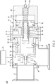
Fig. 2 to Fig. 4 , theright angle valve 100 provided by an embodiment of the present invention comprises avalve body 10, afixing member 20, adisc spring 30, acover 40, and apiston member 50. - The
valve body 10 is a three way pipe, comprising acavity 11 and afirst pipe 12 and asecond pipe 13 that are connected with thecavity 11. Thefirst pipe 12 and thecavity 11 are arranged in an axial alignment. Thefirst pipe 12 and thesecond pipe 13 form a right angle arrangement. - The
fixing member 20 is formed in a barrel shape structure and fixed on one end of thevalve body 10 away from thefirst pipe 12. Thefixing member 20 is provided with a combiningend 21 inserted into thecavity 11. - The
disc spring 30 has one end thereof combined with a combiningend 21 of thefixing member 20, while the other end thereof is connected with asealing member 31 for sealing the inner end of thefirst pipe 12, so as to optionally open or close to allow or block the connection between thefirst pipe 12 and thecavity 11. - The
cover 40 is fixed on one end of thevalve body 10 away from thefirst pipe 12 and arranged on the outer side of thefixing member 20. Thecover 40 includes aninner space 41. Anair inflow portion 42 is disposed on thecover 40 adjacent to thevalve body 10. Theair inflow portion 42 comprises anair inlet 421 which is connected with theinner space 41 for contacting an outer air source, such that the air is input into theinner space 41. Furthermore, one end of thecover 40 away from theair inflow portion 42 is provided with a sealedend 43. The sealedend 43 includes asilencing member 44, wherein the inner end of thesilencing member 44 is connected with theinner space 41 for balancing the inner pressure and the outer pressure of thecover 40. In addition, the sealedend 43 of thecover 40 is provided with apositioning recess 45 which is connected with theinner space 41 and the inner end of the silencingmember 44. - The
piston member 50 is slidingly disposed inside thecover 40. In an embodiment of the present invention, thepiston member 50 includes apiston body 51 which is slidingly disposed in theinner space 41. Thepiston body 51 is combined with a controllingshaft 52. The controllingshaft 52 pass through theair inflow portion 42 and the fixingmember 20, wherein one end of the controllingshaft 52 is combined with the sealingmember 31. When thepiston member 50 moves, the sealingmember 31 optionally opens or closes thefirst pipe 12. Further, thepiston body 51 is axially and concavely provided with aspring recess 53 which receives aspring 54, such that thespring 54 is disposed between thespring recess 53 and thepositioning recess 45 of the sealedend 43, thereby providing the recovering function of thepiston member 50. In addition, a positioningmember 55 is disposed in thespring recess 53, and the positioningmember 55 is formed in a T shape, so as to be inserted into thespring 54 in order to position thespring 54. - An embodiment of the present invention further comprises a covering measure. When the
piston member 50 drives the sealingmember 31 to move away from the inner end of thefirst pipe 12 and enables the air to flow, thedisc spring 30 is covered, so that thedisc spring 30 is prevented from being exposed to the flowing air. As a result, thedisc spring 30 is not stuck and attached by foreign objects or dust in the air, facilitating the normal operation of thedisc spring 30. - The covering measure includes a
sleeve 60, which comprises a fixingend 61 and afree end 62. Thesleeve 60 is mounted around the fixingmember 20, such that the fixingend 61 is fastened with the fixingmember 20 by use of screws or bolts, and thefree end 62 surrounds the combiningend 21 of the fixingmember 20 and thedisc spring 30. Also, the outer diameter of thefree end 62 of thesleeve 60 is substantially equal to the outer diameter of the sealingmember 31. When the sealingmember 31 moves away from the inner end of thefirst pipe 12 to the largest distance, one end of the sealingmember 31 away from the inner side of thefirst pipe 12 contacts thefree end 62, forming a blockage status. Also, the sealingmember 31 seals thefree end 62 of thesleeve 60, whereby thedisc spring 30 is completely compressed into thesleeve 60. Therefore, a covering and protecting effect is provided upon thedisc spring 30. - Furthermore, an embodiment of the present invention includes a
heating device 70, which heats thevalve body 10 by in a contact or non-contact manner. By use of heating, when thefirst pipe 12 is opened, the micro size foreign objects or matters are burned in a high temperature environment. Therefore, foreign objects do not stick or accumulate in the pipe. - Also, a
heat insulating plate 71 is disposed between thevalve body 10 and thecover 40. When theheating device 70 heats thevalve body 10, the heat is transmitted to thecover 40, so as to prevent the adverse effects due to the operation of thepiston member 50 and the air leakage from happening. - Referring to
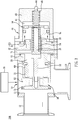
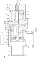
Fig. 3 andFig. 4 , thepiston member 50 moves to open thefirst pipe 12. As shown byFig. 3 , by inputting a high pressure air from the outside, when thepiston member 50 pushes thepiston body 51 to move toward the sealedend 43 of thecover 40, thepiston body 51, by use of the controllingshaft 52, drives the sealingmember 31 to gradually move away from the inner end of thefirst pipe 12, whereby the connection between thefirst pipe 12 and thesecond pipe 13 is established. At the meantime, thedisc spring 30 bears a force to be compressed. As shown byFig. 4 , when thepiston body 51 reaches the movement limitation, thefirst pipe 12 is completely opened, and the inner surface of the sealingmember 31 rests against thefree end 62 of thesleeve 60 to form a blockage structure, such that thedisc spring 30 is completely covered in the sealingmember 31 and thesleeve 60. Therefore, when the air is flowing, thedisc spring 30 is prevented from being exposed in the flowing air, whereby thedisc spring 30 is not stuck and attached by foreign objects and dust in the air, thus facilitating the normal operation of thedisc spring 30. Further, when the valve is closed to block the high pressure air from the outside, by use of the resilient force provided by thedisc spring 30 and thespring 54, the position of thepiston member 50 is recovered, such that thefirst pipe 12 is blocked by the sealingmember 31 to block the flowing air. - Referring to
Fig. 5 andFig. 6 illustrating another embodiment of the present invention, the elements/structures identical and similar to the corresponding elements cited in the previous drawing are marked with identical numberings. The covering measure includes asleeve 80 which is fixedly combined with the sealingmember 31 and surrounds thedisc spring 30. Thesleeve 80 is allowed to be integrally formed with the sealingmember 31. Also, the combiningend 21 of the fixingmember 20 is provided with a heldportion 22. When thepiston member 50 drives the sealingmember 31 to open against thefirst pipe 12, thesleeve 80 gradually moves along with the sealingmember 31 toward the fixingmember 20; when the sealingmember 31 is completely open against thefirst pipe 12, thesleeve 80 rests against the heldportion 22 of the fixingmember 20, whereby thedisc spring 30 is completely covered, achieving the aforementioned covering and protecting effect. - To sum up, by use of the covering measure, when the sealing
member 31 opens to allow the air flowing, thedisc spring 30 is covered in thesleeve 60 orsleeve 80, such that thedisc spring 30 is prevented from being stuck or attached by foreign objects in the flowing air, assuring the normal operation of thedisc spring 30. - Furthermore, through the
heating device 70 heating thevalve body 10, when thefirst pipe 12 is opened, the foreign matters or objects in thevalve body 10 are burned by the high temperature heat, preventing the foreign objects from sticking or accumulating in the pipe. - Although particular embodiments of the invention have been described in detail for purposes of illustration, various modifications and enhancements may be made without departing from the scope of the invention. Accordingly, the invention is not to be limited except as by the appended claims.
Claims (9)
- A right angle valve (100), comprising:a valve body (10) including a cavity (11) and a first pipe (12) and a second pipe (13) connected with the cavity (11);a fixing member (20) fixed to the valve body (10), the fixing member (20) provided with a combining end (21) inserted into the cavity (11);a disc spring (30) with one end thereof combined to the combining end (21) and the other end thereof connected with a sealing member (30) for sealing an inner end of the first pipe (12);a cover (40) fixed to an end of the valve body (10) away from the first pipe (12);a piston member (50) slidingly disposed in the cover (40), one end of the piston member (50) combined to the sealing member (31); anda covering measure including a sleeve (60), wherein the covering measure covers the disc spring (30) when the piston member (50) drives the sealing member (31) to move away from the inner end of the first pipe (12) to allow an air inflow, such that the disc spring (30) is prevented from being exposed to the flowing air,characterized in thatthe sleeve (60) comprises a fixing end (61) and a free end (62), the fixing end (61) fixedly combined with the fixing member, the free end (62) surrounding the combining end (21) of the fixing member (20) and the disc spring (30), wherein the sealing member (31) rests against the free end (62) when the sealing member (31) moves away from the inner end of the first pipe (12) to the largest distance.
- The right angle valve (100) of claim 1, wherein the fixing end (61) is fastened with the fixing member (20).
- The right angle valve (100) of claim 1, wherein the cover (40) is provided with an inner space (41), the piston member (50) includes a piston body (51) slidingly disposed in the inner space (41), and an air inflow portion (42) connected with the inner space (41) is disposed at the cover (40) adjacent to the valve body (10).
- The right angle valve (100) of claim 3, wherein the piston body (51) is connected with a controlling shaft (52), the controlling shaft (52) passing through the fixing member (20) and is connected with the sealing member (31).
- The right angle valve (100) of claim 3, wherein the piston body (51) is concavely provided with a spring recess (53), the cover (40) is provided with a sealed end (43), and a spring (54) is disposed between the spring recess (53) and the sealed end (43).
- The right angle valve (100) of claim 5, wherein a positioning member (55) is disposed in the spring recess (53) to be inserted in the spring (54).
- The right angle valve (100) of claim 5, wherein the sealed end (43) of the cover (40) is provided with a silencing member (44), wherein an inner end of the silencing member (44) contacts the inner space (41).
- The right angle valve (100) of claim 1, further comprising a heating device (70) for heating the valve body (10).
- The right angle valve (100) of claim 8, further comprising a heat insulating plate 71) disposed between the valve body (10) and the cover (40).
Priority Applications (1)
| Application Number | Priority Date | Filing Date | Title |
|---|---|---|---|
| EP16186011.9A EP3287681B1 (en) | 2016-08-26 | 2016-08-26 | Right angle valve |
Applications Claiming Priority (1)
| Application Number | Priority Date | Filing Date | Title |
|---|---|---|---|
| EP16186011.9A EP3287681B1 (en) | 2016-08-26 | 2016-08-26 | Right angle valve |
Publications (2)
| Publication Number | Publication Date |
|---|---|
| EP3287681A1 EP3287681A1 (en) | 2018-02-28 |
| EP3287681B1 true EP3287681B1 (en) | 2020-02-19 |
Family
ID=56852098
Family Applications (1)
| Application Number | Title | Priority Date | Filing Date |
|---|---|---|---|
| EP16186011.9A Active EP3287681B1 (en) | 2016-08-26 | 2016-08-26 | Right angle valve |
Country Status (1)
| Country | Link |
|---|---|
| EP (1) | EP3287681B1 (en) |
Families Citing this family (1)
| Publication number | Priority date | Publication date | Assignee | Title |
|---|---|---|---|---|
| FR3103530B1 (en) * | 2019-11-26 | 2021-11-05 | Asco Sas | Cryogenic valve with reduced heat transfer |
Family Cites Families (5)
| Publication number | Priority date | Publication date | Assignee | Title |
|---|---|---|---|---|
| US5678595A (en) * | 1995-12-21 | 1997-10-21 | Benkan Corporation | Vacuum exhaust valve |
| JP3778866B2 (en) * | 2002-03-20 | 2006-05-24 | Smc株式会社 | Vacuum valve with heater |
| JP5066724B2 (en) * | 2007-01-17 | 2012-11-07 | Smc株式会社 | High vacuum valve |
| US8196893B2 (en) * | 2008-04-09 | 2012-06-12 | Mks Instruments, Inc. | Isolation valve with corrosion protected and heat transfer enhanced valve actuator and closure apparatus and method |
| KR101013137B1 (en) * | 2010-11-19 | 2011-02-10 | 이동민 | Valve for vaccuum process |
-
2016
- 2016-08-26 EP EP16186011.9A patent/EP3287681B1/en active Active
Non-Patent Citations (1)
| Title |
|---|
| None * |
Also Published As
| Publication number | Publication date |
|---|---|
| EP3287681A1 (en) | 2018-02-28 |
Similar Documents
| Publication | Publication Date | Title |
|---|---|---|
| US9395006B2 (en) | Check valve | |
| JP5435439B2 (en) | Two-way valve | |
| US20180051820A1 (en) | Right angle valve | |
| JP2018153685A5 (en) | ||
| EP3108167B1 (en) | Actuator apparatus having integral yoke tubing | |
| RU2614651C2 (en) | Thermostatic valve, in particular radiator valve | |
| US10941865B2 (en) | Steam valve, valve and steam turbine facility | |
| WO2017156831A1 (en) | Gas proportional valve | |
| CN112628455B (en) | Membrane for a power valve | |
| CA2868942A1 (en) | Valve seat for floating ball valve | |
| EP3287681B1 (en) | Right angle valve | |
| JP2012233579A (en) | Valve | |
| JP2018534499A (en) | Pressure limiting valve | |
| KR20180029714A (en) | Right angle valve | |
| AR119332A1 (en) | ARRANGEMENT OF A VALVE | |
| JP6002933B2 (en) | Check valve and water heater provided with the same | |
| RU2647577C2 (en) | Safety shut-off device with controlled valve disc (versions) | |
| US20150377371A1 (en) | Intelligent Pressure Relief Device For A Double Isolation Valve | |
| WO2014147915A1 (en) | Leakage prevention seal, and pump for nuclear reactor cooling material | |
| JP6257717B1 (en) | Right angle valve | |
| KR20170054890A (en) | Air pressure valve for controlling high temperature fluid | |
| JP2007253325A (en) | Thermal deburring facility by rapid deaeration | |
| WO2014012496A1 (en) | Sealing device in a valve and a valve with the same | |
| TWI792686B (en) | Magnetronic Fluid Interrupter | |
| JP6220273B2 (en) | Relief valve |
Legal Events
| Date | Code | Title | Description |
|---|---|---|---|
| PUAI | Public reference made under article 153(3) epc to a published international application that has entered the european phase |
Free format text: ORIGINAL CODE: 0009012 |
|
| STAA | Information on the status of an ep patent application or granted ep patent |
Free format text: STATUS: THE APPLICATION HAS BEEN PUBLISHED |
|
| AK | Designated contracting states |
Kind code of ref document: A1 Designated state(s): AL AT BE BG CH CY CZ DE DK EE ES FI FR GB GR HR HU IE IS IT LI LT LU LV MC MK MT NL NO PL PT RO RS SE SI SK SM TR |
|
| AX | Request for extension of the european patent |
Extension state: BA ME |
|
| STAA | Information on the status of an ep patent application or granted ep patent |
Free format text: STATUS: REQUEST FOR EXAMINATION WAS MADE |
|
| 17P | Request for examination filed |
Effective date: 20180828 |
|
| RBV | Designated contracting states (corrected) |
Designated state(s): AL AT BE BG CH CY CZ DE DK EE ES FI FR GB GR HR HU IE IS IT LI LT LU LV MC MK MT NL NO PL PT RO RS SE SI SK SM TR |
|
| GRAP | Despatch of communication of intention to grant a patent |
Free format text: ORIGINAL CODE: EPIDOSNIGR1 |
|
| STAA | Information on the status of an ep patent application or granted ep patent |
Free format text: STATUS: GRANT OF PATENT IS INTENDED |
|
| RIC1 | Information provided on ipc code assigned before grant |
Ipc: F16K 49/00 20060101AFI20190820BHEP Ipc: F16K 1/36 20060101ALI20190820BHEP Ipc: F16K 51/02 20060101ALI20190820BHEP |
|
| INTG | Intention to grant announced |
Effective date: 20190916 |
|
| GRAS | Grant fee paid |
Free format text: ORIGINAL CODE: EPIDOSNIGR3 |
|
| GRAA | (expected) grant |
Free format text: ORIGINAL CODE: 0009210 |
|
| STAA | Information on the status of an ep patent application or granted ep patent |
Free format text: STATUS: THE PATENT HAS BEEN GRANTED |
|
| AK | Designated contracting states |
Kind code of ref document: B1 Designated state(s): AL AT BE BG CH CY CZ DE DK EE ES FI FR GB GR HR HU IE IS IT LI LT LU LV MC MK MT NL NO PL PT RO RS SE SI SK SM TR |
|
| REG | Reference to a national code |
Ref country code: CH Ref legal event code: EP |
|
| REG | Reference to a national code |
Ref country code: DE Ref legal event code: R096 Ref document number: 602016029948 Country of ref document: DE |
|
| REG | Reference to a national code |
Ref country code: AT Ref legal event code: REF Ref document number: 1235360 Country of ref document: AT Kind code of ref document: T Effective date: 20200315 |
|
| REG | Reference to a national code |
Ref country code: IE Ref legal event code: FG4D |
|
| REG | Reference to a national code |
Ref country code: NL Ref legal event code: MP Effective date: 20200219 |
|
| PG25 | Lapsed in a contracting state [announced via postgrant information from national office to epo] |
Ref country code: RS Free format text: LAPSE BECAUSE OF FAILURE TO SUBMIT A TRANSLATION OF THE DESCRIPTION OR TO PAY THE FEE WITHIN THE PRESCRIBED TIME-LIMIT Effective date: 20200219 Ref country code: FI Free format text: LAPSE BECAUSE OF FAILURE TO SUBMIT A TRANSLATION OF THE DESCRIPTION OR TO PAY THE FEE WITHIN THE PRESCRIBED TIME-LIMIT Effective date: 20200219 Ref country code: NO Free format text: LAPSE BECAUSE OF FAILURE TO SUBMIT A TRANSLATION OF THE DESCRIPTION OR TO PAY THE FEE WITHIN THE PRESCRIBED TIME-LIMIT Effective date: 20200519 |
|
| REG | Reference to a national code |
Ref country code: LT Ref legal event code: MG4D |
|
| PG25 | Lapsed in a contracting state [announced via postgrant information from national office to epo] |
Ref country code: GR Free format text: LAPSE BECAUSE OF FAILURE TO SUBMIT A TRANSLATION OF THE DESCRIPTION OR TO PAY THE FEE WITHIN THE PRESCRIBED TIME-LIMIT Effective date: 20200520 Ref country code: BG Free format text: LAPSE BECAUSE OF FAILURE TO SUBMIT A TRANSLATION OF THE DESCRIPTION OR TO PAY THE FEE WITHIN THE PRESCRIBED TIME-LIMIT Effective date: 20200519 Ref country code: HR Free format text: LAPSE BECAUSE OF FAILURE TO SUBMIT A TRANSLATION OF THE DESCRIPTION OR TO PAY THE FEE WITHIN THE PRESCRIBED TIME-LIMIT Effective date: 20200219 Ref country code: SE Free format text: LAPSE BECAUSE OF FAILURE TO SUBMIT A TRANSLATION OF THE DESCRIPTION OR TO PAY THE FEE WITHIN THE PRESCRIBED TIME-LIMIT Effective date: 20200219 Ref country code: IS Free format text: LAPSE BECAUSE OF FAILURE TO SUBMIT A TRANSLATION OF THE DESCRIPTION OR TO PAY THE FEE WITHIN THE PRESCRIBED TIME-LIMIT Effective date: 20200619 Ref country code: LV Free format text: LAPSE BECAUSE OF FAILURE TO SUBMIT A TRANSLATION OF THE DESCRIPTION OR TO PAY THE FEE WITHIN THE PRESCRIBED TIME-LIMIT Effective date: 20200219 |
|
| PG25 | Lapsed in a contracting state [announced via postgrant information from national office to epo] |
Ref country code: NL Free format text: LAPSE BECAUSE OF FAILURE TO SUBMIT A TRANSLATION OF THE DESCRIPTION OR TO PAY THE FEE WITHIN THE PRESCRIBED TIME-LIMIT Effective date: 20200219 |
|
| PG25 | Lapsed in a contracting state [announced via postgrant information from national office to epo] |
Ref country code: PT Free format text: LAPSE BECAUSE OF FAILURE TO SUBMIT A TRANSLATION OF THE DESCRIPTION OR TO PAY THE FEE WITHIN THE PRESCRIBED TIME-LIMIT Effective date: 20200712 Ref country code: RO Free format text: LAPSE BECAUSE OF FAILURE TO SUBMIT A TRANSLATION OF THE DESCRIPTION OR TO PAY THE FEE WITHIN THE PRESCRIBED TIME-LIMIT Effective date: 20200219 Ref country code: SK Free format text: LAPSE BECAUSE OF FAILURE TO SUBMIT A TRANSLATION OF THE DESCRIPTION OR TO PAY THE FEE WITHIN THE PRESCRIBED TIME-LIMIT Effective date: 20200219 Ref country code: DK Free format text: LAPSE BECAUSE OF FAILURE TO SUBMIT A TRANSLATION OF THE DESCRIPTION OR TO PAY THE FEE WITHIN THE PRESCRIBED TIME-LIMIT Effective date: 20200219 Ref country code: EE Free format text: LAPSE BECAUSE OF FAILURE TO SUBMIT A TRANSLATION OF THE DESCRIPTION OR TO PAY THE FEE WITHIN THE PRESCRIBED TIME-LIMIT Effective date: 20200219 Ref country code: SM Free format text: LAPSE BECAUSE OF FAILURE TO SUBMIT A TRANSLATION OF THE DESCRIPTION OR TO PAY THE FEE WITHIN THE PRESCRIBED TIME-LIMIT Effective date: 20200219 Ref country code: ES Free format text: LAPSE BECAUSE OF FAILURE TO SUBMIT A TRANSLATION OF THE DESCRIPTION OR TO PAY THE FEE WITHIN THE PRESCRIBED TIME-LIMIT Effective date: 20200219 Ref country code: CZ Free format text: LAPSE BECAUSE OF FAILURE TO SUBMIT A TRANSLATION OF THE DESCRIPTION OR TO PAY THE FEE WITHIN THE PRESCRIBED TIME-LIMIT Effective date: 20200219 Ref country code: LT Free format text: LAPSE BECAUSE OF FAILURE TO SUBMIT A TRANSLATION OF THE DESCRIPTION OR TO PAY THE FEE WITHIN THE PRESCRIBED TIME-LIMIT Effective date: 20200219 |
|
| REG | Reference to a national code |
Ref country code: AT Ref legal event code: MK05 Ref document number: 1235360 Country of ref document: AT Kind code of ref document: T Effective date: 20200219 |
|
| REG | Reference to a national code |
Ref country code: DE Ref legal event code: R097 Ref document number: 602016029948 Country of ref document: DE |
|
| PLBE | No opposition filed within time limit |
Free format text: ORIGINAL CODE: 0009261 |
|
| STAA | Information on the status of an ep patent application or granted ep patent |
Free format text: STATUS: NO OPPOSITION FILED WITHIN TIME LIMIT |
|
| 26N | No opposition filed |
Effective date: 20201120 |
|
| PG25 | Lapsed in a contracting state [announced via postgrant information from national office to epo] |
Ref country code: IT Free format text: LAPSE BECAUSE OF FAILURE TO SUBMIT A TRANSLATION OF THE DESCRIPTION OR TO PAY THE FEE WITHIN THE PRESCRIBED TIME-LIMIT Effective date: 20200219 Ref country code: AT Free format text: LAPSE BECAUSE OF FAILURE TO SUBMIT A TRANSLATION OF THE DESCRIPTION OR TO PAY THE FEE WITHIN THE PRESCRIBED TIME-LIMIT Effective date: 20200219 |
|
| PG25 | Lapsed in a contracting state [announced via postgrant information from national office to epo] |
Ref country code: SI Free format text: LAPSE BECAUSE OF FAILURE TO SUBMIT A TRANSLATION OF THE DESCRIPTION OR TO PAY THE FEE WITHIN THE PRESCRIBED TIME-LIMIT Effective date: 20200219 Ref country code: PL Free format text: LAPSE BECAUSE OF FAILURE TO SUBMIT A TRANSLATION OF THE DESCRIPTION OR TO PAY THE FEE WITHIN THE PRESCRIBED TIME-LIMIT Effective date: 20200219 |
|
| PG25 | Lapsed in a contracting state [announced via postgrant information from national office to epo] |
Ref country code: MC Free format text: LAPSE BECAUSE OF FAILURE TO SUBMIT A TRANSLATION OF THE DESCRIPTION OR TO PAY THE FEE WITHIN THE PRESCRIBED TIME-LIMIT Effective date: 20200219 |
|
| PG25 | Lapsed in a contracting state [announced via postgrant information from national office to epo] |
Ref country code: LU Free format text: LAPSE BECAUSE OF NON-PAYMENT OF DUE FEES Effective date: 20200826 |
|
| REG | Reference to a national code |
Ref country code: BE Ref legal event code: MM Effective date: 20200831 |
|
| PG25 | Lapsed in a contracting state [announced via postgrant information from national office to epo] |
Ref country code: BE Free format text: LAPSE BECAUSE OF NON-PAYMENT OF DUE FEES Effective date: 20200831 Ref country code: IE Free format text: LAPSE BECAUSE OF NON-PAYMENT OF DUE FEES Effective date: 20200826 |
|
| PG25 | Lapsed in a contracting state [announced via postgrant information from national office to epo] |
Ref country code: TR Free format text: LAPSE BECAUSE OF FAILURE TO SUBMIT A TRANSLATION OF THE DESCRIPTION OR TO PAY THE FEE WITHIN THE PRESCRIBED TIME-LIMIT Effective date: 20200219 Ref country code: MT Free format text: LAPSE BECAUSE OF FAILURE TO SUBMIT A TRANSLATION OF THE DESCRIPTION OR TO PAY THE FEE WITHIN THE PRESCRIBED TIME-LIMIT Effective date: 20200219 Ref country code: CY Free format text: LAPSE BECAUSE OF FAILURE TO SUBMIT A TRANSLATION OF THE DESCRIPTION OR TO PAY THE FEE WITHIN THE PRESCRIBED TIME-LIMIT Effective date: 20200219 |
|
| PG25 | Lapsed in a contracting state [announced via postgrant information from national office to epo] |
Ref country code: MK Free format text: LAPSE BECAUSE OF FAILURE TO SUBMIT A TRANSLATION OF THE DESCRIPTION OR TO PAY THE FEE WITHIN THE PRESCRIBED TIME-LIMIT Effective date: 20200219 Ref country code: AL Free format text: LAPSE BECAUSE OF FAILURE TO SUBMIT A TRANSLATION OF THE DESCRIPTION OR TO PAY THE FEE WITHIN THE PRESCRIBED TIME-LIMIT Effective date: 20200219 |
|
| PGFP | Annual fee paid to national office [announced via postgrant information from national office to epo] |
Ref country code: GB Payment date: 20230824 Year of fee payment: 8 Ref country code: CH Payment date: 20230902 Year of fee payment: 8 |
|
| PGFP | Annual fee paid to national office [announced via postgrant information from national office to epo] |
Ref country code: FR Payment date: 20230821 Year of fee payment: 8 Ref country code: DE Payment date: 20230828 Year of fee payment: 8 |