EP3287368A1 - Small store suspension and release unit - Google Patents
Small store suspension and release unit Download PDFInfo
- Publication number
- EP3287368A1 EP3287368A1 EP17187956.2A EP17187956A EP3287368A1 EP 3287368 A1 EP3287368 A1 EP 3287368A1 EP 17187956 A EP17187956 A EP 17187956A EP 3287368 A1 EP3287368 A1 EP 3287368A1
- Authority
- EP
- European Patent Office
- Prior art keywords
- suspension
- store
- suspension hook
- release unit
- latch
- Prior art date
- Legal status (The legal status is an assumption and is not a legal conclusion. Google has not performed a legal analysis and makes no representation as to the accuracy of the status listed.)
- Granted
Links
Images



Classifications
-
- B—PERFORMING OPERATIONS; TRANSPORTING
- B64—AIRCRAFT; AVIATION; COSMONAUTICS
- B64D—EQUIPMENT FOR FITTING IN OR TO AIRCRAFT; FLIGHT SUITS; PARACHUTES; ARRANGEMENT OR MOUNTING OF POWER PLANTS OR PROPULSION TRANSMISSIONS IN AIRCRAFT
- B64D1/00—Dropping, ejecting, releasing or receiving articles, liquids, or the like, in flight
- B64D1/02—Dropping, ejecting, or releasing articles
-
- B—PERFORMING OPERATIONS; TRANSPORTING
- B64—AIRCRAFT; AVIATION; COSMONAUTICS
- B64D—EQUIPMENT FOR FITTING IN OR TO AIRCRAFT; FLIGHT SUITS; PARACHUTES; ARRANGEMENT OR MOUNTING OF POWER PLANTS OR PROPULSION TRANSMISSIONS IN AIRCRAFT
- B64D1/00—Dropping, ejecting, releasing or receiving articles, liquids, or the like, in flight
- B64D1/02—Dropping, ejecting, or releasing articles
- B64D1/04—Dropping, ejecting, or releasing articles the articles being explosive, e.g. bombs
- B64D1/06—Bomb releasing; Bomb doors
-
- B—PERFORMING OPERATIONS; TRANSPORTING
- B64—AIRCRAFT; AVIATION; COSMONAUTICS
- B64D—EQUIPMENT FOR FITTING IN OR TO AIRCRAFT; FLIGHT SUITS; PARACHUTES; ARRANGEMENT OR MOUNTING OF POWER PLANTS OR PROPULSION TRANSMISSIONS IN AIRCRAFT
- B64D7/00—Arrangement of military equipment, e.g. armaments, armament accessories or military shielding, in aircraft; Adaptations of armament mountings for aircraft
- B64D7/08—Arrangement of rocket launchers
-
- F—MECHANICAL ENGINEERING; LIGHTING; HEATING; WEAPONS; BLASTING
- F41—WEAPONS
- F41F—APPARATUS FOR LAUNCHING PROJECTILES OR MISSILES FROM BARRELS, e.g. CANNONS; LAUNCHERS FOR ROCKETS OR TORPEDOES; HARPOON GUNS
- F41F5/00—Launching-apparatus for gravity-propelled missiles or projectiles
-
- H—ELECTRICITY
- H01—ELECTRIC ELEMENTS
- H01R—ELECTRICALLY-CONDUCTIVE CONNECTIONS; STRUCTURAL ASSOCIATIONS OF A PLURALITY OF MUTUALLY-INSULATED ELECTRICAL CONNECTING ELEMENTS; COUPLING DEVICES; CURRENT COLLECTORS
- H01R13/00—Details of coupling devices of the kinds covered by groups H01R12/70 or H01R24/00 - H01R33/00
- H01R13/62—Means for facilitating engagement or disengagement of coupling parts or for holding them in engagement
- H01R13/629—Additional means for facilitating engagement or disengagement of coupling parts, e.g. aligning or guiding means, levers, gas pressure electrical locking indicators, manufacturing tolerances
- H01R13/633—Additional means for facilitating engagement or disengagement of coupling parts, e.g. aligning or guiding means, levers, gas pressure electrical locking indicators, manufacturing tolerances for disengagement only
- H01R13/635—Additional means for facilitating engagement or disengagement of coupling parts, e.g. aligning or guiding means, levers, gas pressure electrical locking indicators, manufacturing tolerances for disengagement only by mechanical pressure, e.g. spring force
Definitions
- This invention concerns a suspension and release unit particularly (although not exclusively) for attaching small and relatively lightweight stores to the underside of an aircraft, for example beneath the wings, for release when desired.
- Conventional store suspension and release units for aircraft comprise sway braces used to hold the store steady during carriage in flight, and separate gas-powered pistons which push the store away from the aircraft at the moment of release, so that the store is ejected out of the aircraft slipstream in a controlled manner, along the correct trajectory, without risk of colliding with the aircraft.
- the size and mass of conventional stores makes such power assisted ejection necessary.
- the electrical interface between such suspension and release units and the store for arming, target programming and similar functions is provided by an umbilical cable with a releasable electrical connector at one end attached to the store. This allows the store to be mechanically attached to the suspension and release unit before the electrical connection is made up, making the relatively large and heavy conventional stores easier to load.
- such cables can cause additional drag during separation of the store from the aircraft, necessitating still higher ejection forces.
- Powered ejection systems and umbilical connector cables have therefore been found necessary for conventional stores, but are complex and expensive in both hardware and maintenance costs.
- the suspension and release unit may be made structurally simpler, with either or both of the sway brace and electrical connector used to perform a dual function: in the case of the sway brace, both steadying the store during carriage and ejection upon release; and in the case of the electrical connector, electrical interfacing with the store and ejection upon release.
- the sway brace (or a portion thereof) may be movable under resilient bias to provide the ejection impulse.
- the electrical connector (or a portion thereof) may be movable under resilient bias to provide the ejection impulse.
- Mechanical springs may be used to provide such resilient bias in a particularly straightforward way and are particularly effective in the case of smaller and lighter stores.
- the sway brace (or a portion thereof) may additionally or alternatively be power actuated, e.g. by a gas powered piston or any other suitable means, to provide the ejection impulse.
- the electrical connector (or a portion thereof) may additionally or alternatively be power actuated, e.g. by a gas powered piston or any other suitable means, to provide the ejection impulse.
- the sway brace may comprise a leg which is angularly adjustable for engagement with the store.
- the adjustment may be provided by a lead screw.
- the leg may be height adjustable with respect to a suspension and release hook of the suspension and release unit, to more readily accommodate stores of differing diameters.
- the leg may comprise a pivotally attached foot engageable with the store, the ejection impulse being provided by a torsion spring which biases at least a portion of the foot in a direction outwardly away from the remainder of the suspension and release unit.
- the electrical connector may comprise one or more coil springs which bias at least a portion of the electrical connector in a direction away from the remainder of the suspension and release unit, to provide the ejection impulse.
- the present invention provides safety improvements in a latching mechanism of a store suspension and release unit.
- such units comprise a rotary solenoid actuated primary latch which is releasable to allow a store suspension hook to rotate under spring action and under the weight of the store, thereby releasing the store.
- the primary latch is mechanically interlinked with a safety latch, actuated by a separate rotary solenoid, so that it is necessary to energize the solenoids sequentially in order to release the hook for rotation. Under some conditions ice may form within the latching mechanism which may jam the suspension hook, preventing it from moving sufficiently to release the store upon actuation of the primary latch.
- parts of the primary latch may be free to move sufficiently to prevent them from lockingly re-engaging with the suspension hook and with the safety latch, after the solenoids have been de-energized. This leaves the latching mechanism in an unsafe condition, as once the ice has melted, the store can suddenly and unexpectedly be released.
- the invention therefore provides a store suspension and release unit, as defined in claim 1. Therefore in the event of the suspension hook becoming jammed against movement, e.g. through ice formation, the safety latch is able to move into the locked position to prevent movement of the suspension hook and release of the store, no matter whether or not the primary latch is able to re-engage the suspension hook.
- the safety latch is engageable with the primary latch to prevent actuation of the primary latch and in the unlocked position the safety latch allows actuation of the primary latch.
- the safety latch is primarily actuated by a solenoid or similar electrically powered actuator.
- the suspension hook comprises a nib engageable with the distal end of a store suspension lug as a store is offered up to the suspension hook, so as to rotate the suspension hook from a released position to a position in which the suspension hook engages the lug, the safety latch moving into the path of rotation of the nib.
- the safety latch comprises an actuator driven rotary arm having a detent disengageable from the primary latch by operation of the actuator; the rotary arm being drivingly coupled to a detent pawl which is movable out of the path of rotation of the nib by operation of the actuator.
- the safety latch and primary latch mechanism can preferably be disengaged mechanically by means of a manual release override cam.
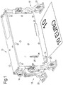
- FIG. 1 shows the illustrative suspension and release unit 10 next to a ten Euro note, to provide an indication of scale.
- the unit 10 comprises a main body 12 for attachment to an aircraft, e.g. beneath a wing.
- the main body has a fixed electrical connector 14 for interfacing the suspension and release unit with the aircraft electrical systems, and a spring biased, movable electrical connector assembly 16 for interfacing with a store (not shown).
- the movable electrical connector assembly 16 is electrically connected to a fixed electrical connector 14 ( Figure 2 ) positioned at the opposite end of the main body 12 relative to the fixed electrical connector 14a.
- Mounted one at either end of the suspension and release unit 10, are respective sway brace assemblies 18.
- Each assembly comprises a pair of adjustable legs 20, described in more detail below.
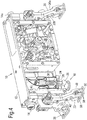
- the movable electrical connector assembly 16 comprises a movable crossbar 22. Reduced diameter ends 24 of the crossbar 22 are slidable in vertical guide slots 26 provided in the unit 10 side covers. A pair of vertical guide rods 28 are fixed to and move with the crossbar 22 and carry at their lower ends mountings 30 for an electrical coupling plug housing 32. Flexible printed circuit ribbon cables 33 and ribbon cable connector plugs 35 connect the electrical coupling plug in the housing 32 to the fixed electrical connector 14. Upper ends of the guide rods 28 are closely slidable in through bores provided in a fixed cross bar 34. Reduced diameter end portions 36 of the fixed cross bar 34 are fixedly received in holes drilled in the unit 10 side covers.
- a respective compression spring 38 is held captive on each guide rod 28, between the cross bars 22, 34.
- the springs 38 are schematically shown fully compressed in Figures 2-4 , to expose a length of each guide rod 28. However normally the springs 38 will remain braced between the cross bars 22, 24 so that the movable cross bar 22, guide rods 28 and coupling plug housing 32 are biased downwardly.
- the guide rods 28 are held captive in the upper cross bar 34 guide bores by circlips 40 and the lower cross bar 22 outer ends are slidably captive in the unit side cover guide slots 26.
- a complementary electrical connector socket (not shown) on the store is offered up for "blind mating" with the coupling plug in the housing 32.
- the store suspension hook 102 within the unit 10 (described in further detail below) is mounted at a vertical level such that compression of the springs 38 is required, via the engaged electrical connector socket and coupling plug, in order to achieve mechanical engagement between the suspension hook and a corresponding suspension lug (not shown) on the store.
- the electrical coupling plug housing 32 is therefore resiliently biased or pre-loaded against the suspended store. When the suspension hook is released, the springs 38 are free to expand, thereby providing an impulse propelling the coupling plug housing and the store downwardly away from the body 12 of the suspension and release unit 10.
- each leg 20 of each sway brace mechanism 18 comprises a pair of machined components 20a, 20b having a central bend to form a shallow V shape.
- the two components of each pair are substantially mirror images of one another and are secured back to back by machine screws 42.
- Upper ends of the components are outwardly cranked away from each other to form upper forks 44 for the reception of drive nuts 46.
- Lower ends of the components are similarly outwardly cranked to form lower forks 48 in which feet 50 are pivotally mounted.
- Trunnions 52 on the drive nuts 46 are received in slots 54 in the forks 44 to connect the upper ends of the legs 20 to the drive nuts 46 (see Figure 6 ).
- Pivot pins 56 mounted across the lower forks 48 pass through vertical webs 58 of the associated foot 50 to pivotally mount it to the leg lower end (see Figures 4 and 6 ).
- Centre pivot pins 60 passing through each leg 20 have an outer end received in a guide slot 62 provided in a centre bracket 64. Inner ends of the centre pivot pins 60 are received in respective C-shaped recesses 66 provided in the adjacent end faces of the body 12 (see Figures 6 and 7 ).
- the respective centre brackets 64 of the two sway brace assemblies are provided one at either end of the body 12 to which they are slidably attached in the same manner.
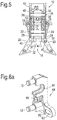
- Each bracket comprises a pair of parallel, horizontally inwardly projecting, mounting and guide shafts 72 which are a close sliding fit in a pair of axially aligned guide slots 68, 70 provided in the ends of the body 12. Inner ends of the mounting and guide shafts 72 project through the guide slots 68, 70 into the body 12 interior. Washers 74 and circlips 76 are fitted about the shaft 72 inner ends to hold the centre bracket 64 captive but vertically slidable in the guide slots 68, 70 (see Figures 5 , 6 , 6a and 7 ).
- the inner face of the bracket 64 has a spacer 78 secured to it by a machine screw 80.
- a torsion spring 82 is mounted on the spacer 78 and has opposed arms braced in slots 84 formed in each leg 20 of the sway brace assembly 18.
- Each slot 84 is formed by abutting chamfered portions on the "knee" of the central bend in each of the components making up the leg 20 concerned. In this way, the two legs making up each sway brace assembly are resiliently biased away from each other, so that the centre pivot pins 60 are biased towards the outer ends of the centre bracket guide slots 62 and towards the outer ends of the limbs of the C-shaped recesses 66.
- the feet 50 of the sway brace 18 are further below the coupling plug housing 32 than when the sway brace is in the upper position.
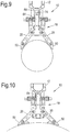
- the lower position is therefore more suitable for steeply curving (small diameter, e.g. down to 3 inch, 76.2 mm) store cross-sections; whereas the upper position is more suitable for more gently curving store cross-sections (larger diameters, e.g. up to 12 inches, 305mm).
- the centre bracket 64 also carries a bearing yoke 86 for a lead screw 88 having oppositely handed threads at each end.
- the drive nuts 46 are threadingly mounted one on each of these threads.
- the lead screw may be turned by a wrench or drive key fitted to hexagonal-sectioned end portions 90.
- a hollow grub screw 92 contains a spring loaded ball detent engageable in a series of pits 94 around the circumference of the lead screw 88, to prevent rotation of the lead screw in the bracket 64 under shock and vibration. With the sway braces set at the appropriate height for the store diameter, the store is blind mated to the electrical connector assembly 16 and engaged by the suspension hook 102.
- the sway braces 18 are then brought into firm engagement with the body of the store by turning the lead screw 88 to move the drive nuts 46 outwardly.
- the upper ends of the sway brace legs 20 are thus moved outwardly.
- the centre pivot pins 60 are constrained against vertical movement and against outward horizontal movement by the ends of the centre bracket slots 52 and of the C-shaped guide slots 66.
- the lower ends of the sway brace legs 20 thus move inwardly towards the store.
- the centre pivot pins 62 cannot move along the guide slots 62 and the sway brace assemblies are therefore locked against up or down sliding movement, as the case may be.
- each foot 50 pivot pin 56 carries a torsion spring 100 wrapped around it.
- One limb 96 of the torsion spring is trapped in a recess defined between the two components of the leg 20 and the other limb 98 of the torsion spring is received in a recess formed inside the base of the foot 50.
- the inner part of each foot is resiliently biased in a direction downwardly and outwardly away from the body 12 of the suspension and release unit 10.
- the inner parts of the feet 50 are rotated upwardly towards the body 12 of the suspension and release unit 10, so as to preload the torsion springs 100.
- the torsion springs 100 rotate the inner portions of the feet 50 downwardly and outwardly away from the suspension and release unit body 12, to provide an ejection impulse to the store, with a "flick" action.
- the suspension hook 102 and its latching mechanisms are best seen in Figures 2-4 .
- the hook is shown in the engaged position, for engaging the suspension lug of a store (not shown).
- the suspension hook 102 is mounted for rotation on a pivot shaft 104 and is biased towards the disengaged position by a torsion spring 106.
- the shaft 104 also carries a nib 108 fixed for rotation with the hook 102.
- the primary latch mechanism comprises a rotary solenoid 114, a first rotary arm 116 mounted to the solenoid output shaft, a two-bar "undercentre" linkage 118, a mounting shaft 120, a thrust wheel 124, and a control arm 122 attached to rotate with the hook 102.
- the upper end of the linkage is rotatably mounted on the shaft 120 and the thrust wheel 124 is rotatably mounted on a pivot shaft connecting the two bars of the linkage 118.
- the upper bar of the linkage 118 is biased in the clockwise direction about the shaft 120 by a torsion spring 124a.
- the lower end of the linkage 118 is pivotally connected to the distal end of the control arm 122.
- the first rotary arm 116 is spring biased in the anticlockwise direction, to a horizontal rest position as shown in Figure 2 . In this position, the right hand end of the first rotary arm 116 rests against and supports the thrust wheel 124, thereby preventing the linkage 118 from collapsing under the influence of the springs 106, 124a. With the safety latch disengaged (as further described below), the first rotary arm 116 is free to be rotated in the clockwise direction by the solenoid 114.
- the safety latch mechanism comprises a second rotary solenoid 126, a second rotary arm 128, an icing safety latch 130 and a manual override cam 132.
- the icing safety latch 130 is mounted for rotation on a shaft 134 and is connected to the second rotary arm 128 by a locking pin 136 received in a drive slot 138.
- the second rotary arm 128 is resiliently biased anticlockwise to a generally vertical rest position as shown in Figure 2 . In this position, a detent pin 140 on the left hand end of the first rotary arm 116 is held in a notch in the second rotary arm 128, preventing the first rotary arm from rotating.
- Energising the second solenoid 126 rotates the attached second rotary arm 128 clockwise, disengaging the detent pin 140 from the notch.
- the first rotary arm 116 is thereby free to rotate when the first solenoid 114 is energised.
- Clockwise rotation of the second rotary arm 128 also rotates the icing safety latch 130 anticlockwise about the shaft 134, via the pin and slot connection 136, 138. This moves the locking pin 136 out of the path of rotation of the nib 108, so that the hook 102 is free to rotate anticlockwise to its disengaged position.
- De-energising the second solenoid 126 moves the locking pin 136 back in front of the nib 108 if the hook has jammed, e.g.
- the second rotary arm 128 is biased anticlockwise via the pin and slot connection 136, 138.
- the second rotary arm 128 is prevented from rotating anticlockwise by engagement of the pin 140 in the second rotary arm notch.
- the hook 102 is therefore locked against rotation and prevented from disengaging from the store suspension lug, even if the primary latch mechanism has moved sufficiently so that the first rotary arm 116 right hand end no longer engages the thrust wheel 124 and the linkage 118 has begun to collapse.
- the present disclosure also comprises the following features:
Landscapes
- Engineering & Computer Science (AREA)
- Aviation & Aerospace Engineering (AREA)
- General Engineering & Computer Science (AREA)
- Details Of Connecting Devices For Male And Female Coupling (AREA)
- Hooks, Suction Cups, And Attachment By Adhesive Means (AREA)
- Closing And Opening Devices For Wings, And Checks For Wings (AREA)
- Holders For Apparel And Elements Relating To Apparel (AREA)
Abstract
Description
- This invention concerns a suspension and release unit particularly (although not exclusively) for attaching small and relatively lightweight stores to the underside of an aircraft, for example beneath the wings, for release when desired.
- Conventional store suspension and release units for aircraft comprise sway braces used to hold the store steady during carriage in flight, and separate gas-powered pistons which push the store away from the aircraft at the moment of release, so that the store is ejected out of the aircraft slipstream in a controlled manner, along the correct trajectory, without risk of colliding with the aircraft. The size and mass of conventional stores makes such power assisted ejection necessary. The electrical interface between such suspension and release units and the store for arming, target programming and similar functions is provided by an umbilical cable with a releasable electrical connector at one end attached to the store. This allows the store to be mechanically attached to the suspension and release unit before the electrical connection is made up, making the relatively large and heavy conventional stores easier to load. However, such cables can cause additional drag during separation of the store from the aircraft, necessitating still higher ejection forces. Powered ejection systems and umbilical connector cables have therefore been found necessary for conventional stores, but are complex and expensive in both hardware and maintenance costs.
- The suspension and release unit may be made structurally simpler, with either or both of the sway brace and electrical connector used to perform a dual function: in the case of the sway brace, both steadying the store during carriage and ejection upon release; and in the case of the electrical connector, electrical interfacing with the store and ejection upon release.
- The sway brace (or a portion thereof) may be movable under resilient bias to provide the ejection impulse. Similarly, the electrical connector (or a portion thereof) may be movable under resilient bias to provide the ejection impulse. Mechanical springs may be used to provide such resilient bias in a particularly straightforward way and are particularly effective in the case of smaller and lighter stores. However the sway brace (or a portion thereof) may additionally or alternatively be power actuated, e.g. by a gas powered piston or any other suitable means, to provide the ejection impulse. Similarly, the electrical connector (or a portion thereof) may additionally or alternatively be power actuated, e.g. by a gas powered piston or any other suitable means, to provide the ejection impulse. The sway brace may comprise a leg which is angularly adjustable for engagement with the store. The adjustment may be provided by a lead screw. The leg may be height adjustable with respect to a suspension and release hook of the suspension and release unit, to more readily accommodate stores of differing diameters. The leg may comprise a pivotally attached foot engageable with the store, the ejection impulse being provided by a torsion spring which biases at least a portion of the foot in a direction outwardly away from the remainder of the suspension and release unit.
- The electrical connector may comprise one or more coil springs which bias at least a portion of the electrical connector in a direction away from the remainder of the suspension and release unit, to provide the ejection impulse.
- The present invention provides safety improvements in a latching mechanism of a store suspension and release unit. Typically, such units comprise a rotary solenoid actuated primary latch which is releasable to allow a store suspension hook to rotate under spring action and under the weight of the store, thereby releasing the store. The primary latch is mechanically interlinked with a safety latch, actuated by a separate rotary solenoid, so that it is necessary to energize the solenoids sequentially in order to release the hook for rotation. Under some conditions ice may form within the latching mechanism which may jam the suspension hook, preventing it from moving sufficiently to release the store upon actuation of the primary latch. However under such conditions parts of the primary latch may be free to move sufficiently to prevent them from lockingly re-engaging with the suspension hook and with the safety latch, after the solenoids have been de-energized. This leaves the latching mechanism in an unsafe condition, as once the ice has melted, the store can suddenly and unexpectedly be released.
- The invention therefore provides a store suspension and release unit, as defined in claim 1. Therefore in the event of the suspension hook becoming jammed against movement, e.g. through ice formation, the safety latch is able to move into the locked position to prevent movement of the suspension hook and release of the store, no matter whether or not the primary latch is able to re-engage the suspension hook.
- Preferably in the locked position the safety latch is engageable with the primary latch to prevent actuation of the primary latch and in the unlocked position the safety latch allows actuation of the primary latch.
- Preferably the safety latch is primarily actuated by a solenoid or similar electrically powered actuator.
- Preferably the suspension hook comprises a nib engageable with the distal end of a store suspension lug as a store is offered up to the suspension hook, so as to rotate the suspension hook from a released position to a position in which the suspension hook engages the lug, the safety latch moving into the path of rotation of the nib.
- Preferably the safety latch comprises an actuator driven rotary arm having a detent disengageable from the primary latch by operation of the actuator; the rotary arm being drivingly coupled to a detent pawl which is movable out of the path of rotation of the nib by operation of the actuator. The safety latch and primary latch mechanism can preferably be disengaged mechanically by means of a manual release override cam.
- An illustrative suspension and release unit embodying the invention is described below with reference to the drawings, in which:
-
Figure 1 shows a side perspective view of the illustrative suspension and release unit; -
Figure 2 is a side view of the suspension and release unit ofFigure 1 with a side cover removed; -
Figures 3 and4 are perspective views corresponding toFigure 2 , viewed from different ends of the suspension and release unit respectively; -
Figure 5 is a cross-sectional view taken on line V-V inFigure 2 , showing the sway brace legs adjusted to move the feet closest together; -
Figure 6 is an end view in the direction of arrow VI inFigure 2 ; -
Figure 6a is a perspective view of a centre bracket; -
Figure 7 corresponds toFigure 6 , but shows the centre bracket omitted and one sway brace leg ghosted so that other parts can be seen; -
Figure 8 is a detailed cross-sectional view showing a sway brace foot, and -
Figures 9 and 10 are end views showing the sway brace mechanism in lower and upper positions respectively, adjusted for engagement with schematically indicated small diameter and larger diameter stores respectively. -
Figure 1 shows the illustrative suspension and releaseunit 10 next to a ten Euro note, to provide an indication of scale. Theunit 10 comprises amain body 12 for attachment to an aircraft, e.g. beneath a wing. The main body has a fixedelectrical connector 14 for interfacing the suspension and release unit with the aircraft electrical systems, and a spring biased, movableelectrical connector assembly 16 for interfacing with a store (not shown). The movableelectrical connector assembly 16 is electrically connected to a fixed electrical connector 14 (Figure 2 ) positioned at the opposite end of themain body 12 relative to the fixedelectrical connector 14a. Mounted one at either end of the suspension and releaseunit 10, are respectivesway brace assemblies 18. Each assembly comprises a pair ofadjustable legs 20, described in more detail below. - Referring to
Figures 1-5 , the movableelectrical connector assembly 16 comprises amovable crossbar 22. Reduceddiameter ends 24 of thecrossbar 22 are slidable invertical guide slots 26 provided in theunit 10 side covers. A pair ofvertical guide rods 28 are fixed to and move with thecrossbar 22 and carry at theirlower ends mountings 30 for an electricalcoupling plug housing 32. Flexible printedcircuit ribbon cables 33 and ribbon cable connector plugs 35 connect the electrical coupling plug in thehousing 32 to the fixedelectrical connector 14. Upper ends of theguide rods 28 are closely slidable in through bores provided in afixed cross bar 34. Reduceddiameter end portions 36 of thefixed cross bar 34 are fixedly received in holes drilled in theunit 10 side covers. Arespective compression spring 38 is held captive on eachguide rod 28, between thecross bars springs 38 are schematically shown fully compressed inFigures 2-4 , to expose a length of eachguide rod 28. However normally thesprings 38 will remain braced between thecross bars movable cross bar 22,guide rods 28 andcoupling plug housing 32 are biased downwardly. Theguide rods 28 are held captive in theupper cross bar 34 guide bores bycirclips 40 and thelower cross bar 22 outer ends are slidably captive in the unit sidecover guide slots 26. During mounting of a store for carriage by the suspension andrelease unit 10, a complementary electrical connector socket (not shown) on the store is offered up for "blind mating" with the coupling plug in thehousing 32. That is, the store and the electrical connector socket mounted on it are moved bodily into mating engagement with the coupling plug in thehousing 32. The store suspension hook 102 within the unit 10 (described in further detail below) is mounted at a vertical level such that compression of thesprings 38 is required, via the engaged electrical connector socket and coupling plug, in order to achieve mechanical engagement between the suspension hook and a corresponding suspension lug (not shown) on the store. The electricalcoupling plug housing 32 is therefore resiliently biased or pre-loaded against the suspended store. When the suspension hook is released, thesprings 38 are free to expand, thereby providing an impulse propelling the coupling plug housing and the store downwardly away from thebody 12 of the suspension and releaseunit 10. When the movableelectrical connector assembly 16 reaches its maximum extension, gravity and the momentum of the downwardly moving store (assisted if necessary by spring loading or other biasing of sway brace components as further described below) will cause the electrical coupling plug within thehousing 32 to pull out of the store socket. The store is thereby completely released from the suspension and releaseunit 10 and travels away from the aircraft along a controlled trajectory. - Now referring additionally to
Figures 6-10 , it can be seen that eachleg 20 of eachsway brace mechanism 18 comprises a pair of machinedcomponents machine screws 42. Upper ends of the components are outwardly cranked away from each other to formupper forks 44 for the reception of drive nuts 46. Lower ends of the components are similarly outwardly cranked to formlower forks 48 in whichfeet 50 are pivotally mounted.Trunnions 52 on the drive nuts 46 are received inslots 54 in theforks 44 to connect the upper ends of thelegs 20 to the drive nuts 46 (seeFigure 6 ). Pivot pins 56 mounted across thelower forks 48 pass throughvertical webs 58 of the associatedfoot 50 to pivotally mount it to the leg lower end (seeFigures 4 and6 ). - Centre pivot pins 60 passing through each
leg 20 have an outer end received in aguide slot 62 provided in acentre bracket 64. Inner ends of the centre pivot pins 60 are received in respective C-shapedrecesses 66 provided in the adjacent end faces of the body 12 (seeFigures 6 and 7 ). Therespective centre brackets 64 of the two sway brace assemblies are provided one at either end of thebody 12 to which they are slidably attached in the same manner. Each bracket comprises a pair of parallel, horizontally inwardly projecting, mounting and guideshafts 72 which are a close sliding fit in a pair of axially alignedguide slots body 12. Inner ends of the mounting and guideshafts 72 project through theguide slots body 12 interior.Washers 74 andcirclips 76 are fitted about theshaft 72 inner ends to hold thecentre bracket 64 captive but vertically slidable in theguide slots 68, 70 (seeFigures 5 ,6 ,6a and7 ). - The inner face of the
bracket 64 has aspacer 78 secured to it by amachine screw 80. Atorsion spring 82 is mounted on thespacer 78 and has opposed arms braced inslots 84 formed in eachleg 20 of thesway brace assembly 18. Eachslot 84 is formed by abutting chamfered portions on the "knee" of the central bend in each of the components making up theleg 20 concerned. In this way, the two legs making up each sway brace assembly are resiliently biased away from each other, so that the centre pivot pins 60 are biased towards the outer ends of the centrebracket guide slots 62 and towards the outer ends of the limbs of the C-shapedrecesses 66. Squeezing the legs of a givensway brace assembly 18 together against the bias of thetorsion spring 82 causes each leg to pivot about thedrive nut trunnions 52, so that the centre pivot pins 60 move inwardly along theguide slots 62. The inner ends of the centre pivot pins are thus disengaged from whichever limb of the C-shaped recess they were previously engaged in. The entiresway brace assembly 18 including thecentre bracket 64 may then be slid up or down, whereupon on releasing thelegs 20, the centre pivot pins 60 may engage in the other limbs of the C-shapedrecesses 66. Thesway brace assembly 18 may therefore be moved between two different vertical positions relative to thebody 12 by squeezing thelegs 20 together, and upon release of the legs is automatically locked in the position to which it has been moved. - In the lower position, the
feet 50 of thesway brace 18 are further below the coupling plughousing 32 than when the sway brace is in the upper position. As shown inFigures 9 and 10 , the lower position is therefore more suitable for steeply curving (small diameter, e.g. down to 3 inch, 76.2 mm) store cross-sections; whereas the upper position is more suitable for more gently curving store cross-sections (larger diameters, e.g. up to 12 inches, 305mm). - The
centre bracket 64 also carries a bearingyoke 86 for alead screw 88 having oppositely handed threads at each end. The drive nuts 46 are threadingly mounted one on each of these threads. The lead screw may be turned by a wrench or drive key fitted to hexagonal-sectionedend portions 90. Ahollow grub screw 92 contains a spring loaded ball detent engageable in a series ofpits 94 around the circumference of thelead screw 88, to prevent rotation of the lead screw in thebracket 64 under shock and vibration. With the sway braces set at the appropriate height for the store diameter, the store is blind mated to theelectrical connector assembly 16 and engaged by thesuspension hook 102. The sway braces 18 are then brought into firm engagement with the body of the store by turning thelead screw 88 to move the drive nuts 46 outwardly. The upper ends of thesway brace legs 20 are thus moved outwardly. The centre pivot pins 60 are constrained against vertical movement and against outward horizontal movement by the ends of thecentre bracket slots 52 and of the C-shapedguide slots 66. The lower ends of thesway brace legs 20 thus move inwardly towards the store. When thesway brace legs 20 have been brought into firm engagement with the store, the centre pivot pins 62 cannot move along theguide slots 62 and the sway brace assemblies are therefore locked against up or down sliding movement, as the case may be. - As shown in
Figure 8 , eachfoot 50pivot pin 56 carries atorsion spring 100 wrapped around it. Onelimb 96 of the torsion spring is trapped in a recess defined between the two components of theleg 20 and theother limb 98 of the torsion spring is received in a recess formed inside the base of thefoot 50. In this way, the inner part of each foot is resiliently biased in a direction downwardly and outwardly away from thebody 12 of the suspension andrelease unit 10. As thesway brace legs 20 are brought into firm engagement with the store as described above, the inner parts of thefeet 50 are rotated upwardly towards thebody 12 of the suspension andrelease unit 10, so as to preload the torsion springs 100. Upon release of the suspension hook from the store, the torsion springs 100 rotate the inner portions of thefeet 50 downwardly and outwardly away from the suspension andrelease unit body 12, to provide an ejection impulse to the store, with a "flick" action. - The
suspension hook 102 and its latching mechanisms are best seen inFigures 2-4 . In these Figures, the hook is shown in the engaged position, for engaging the suspension lug of a store (not shown). Thesuspension hook 102 is mounted for rotation on apivot shaft 104 and is biased towards the disengaged position by atorsion spring 106. Theshaft 104 also carries anib 108 fixed for rotation with thehook 102. When a suspension lug attached to a store (not shown) is inserted throughaperture 110 in thebody 12 with thehook 102 in its disengaged position, the leading end of the suspension lug encounters thenib 108 and pushes against it, rotating thehook 102 clockwise as viewed inFigure 2 , against the torsion spring bias, to the position shown. In this position, thehook 102 engages through the lug to mechanically couple the store to the suspension andrelease unit 10. - The primary latch mechanism comprises a
rotary solenoid 114, a first rotary arm 116 mounted to the solenoid output shaft, a two-bar "undercentre"linkage 118, a mountingshaft 120, athrust wheel 124, and acontrol arm 122 attached to rotate with thehook 102. The upper end of the linkage is rotatably mounted on theshaft 120 and thethrust wheel 124 is rotatably mounted on a pivot shaft connecting the two bars of thelinkage 118. The upper bar of thelinkage 118 is biased in the clockwise direction about theshaft 120 by atorsion spring 124a. The lower end of thelinkage 118 is pivotally connected to the distal end of thecontrol arm 122. With thesolenoid 114 de-energised, the first rotary arm 116 is spring biased in the anticlockwise direction, to a horizontal rest position as shown inFigure 2 . In this position, the right hand end of the first rotary arm 116 rests against and supports thethrust wheel 124, thereby preventing thelinkage 118 from collapsing under the influence of thesprings solenoid 114. This moves the right hand end of the arm 116 out of engagement with thethrust wheel 124, so that thelinkage 118 is free to collapse, its upper bar rotating clockwise about theshaft 120, partially under the influence ofspring 124a. As the linkage collapses, thecontrol arm 122 rotates anticlockwise about theshaft 104, partially under the influence of thespring 106. When thelinkage 118 has fully collapsed, the upper bar attains a generally horizontal orientation and thehook 102 is fully disengaged from the store suspension lug, releasing it from theaperture 110. Theelectrical connector assembly 16 and the sway braces 18 (in particular their feet 50) provide an impulse to the store causing it to separate from the suspension andrelease unit 10, as described above. - The safety latch mechanism comprises a second
rotary solenoid 126, a secondrotary arm 128, anicing safety latch 130 and amanual override cam 132. Theicing safety latch 130 is mounted for rotation on ashaft 134 and is connected to the secondrotary arm 128 by alocking pin 136 received in adrive slot 138. The secondrotary arm 128 is resiliently biased anticlockwise to a generally vertical rest position as shown inFigure 2 . In this position, adetent pin 140 on the left hand end of the first rotary arm 116 is held in a notch in the secondrotary arm 128, preventing the first rotary arm from rotating. Energising thesecond solenoid 126 rotates the attached secondrotary arm 128 clockwise, disengaging thedetent pin 140 from the notch. The first rotary arm 116 is thereby free to rotate when thefirst solenoid 114 is energised. Clockwise rotation of the secondrotary arm 128 also rotates theicing safety latch 130 anticlockwise about theshaft 134, via the pin andslot connection locking pin 136 out of the path of rotation of thenib 108, so that thehook 102 is free to rotate anticlockwise to its disengaged position. De-energising thesecond solenoid 126 moves thelocking pin 136 back in front of thenib 108 if the hook has jammed, e.g. due to icing. Then if thenib 108 presses against the lockingpin 136 attempting to rotate it clockwise about the shaft 134 (e.g. if ice melts to unjam the hook 102) the secondrotary arm 128 is biased anticlockwise via the pin andslot connection rotary arm 128 is prevented from rotating anticlockwise by engagement of thepin 140 in the second rotary arm notch. Thehook 102 is therefore locked against rotation and prevented from disengaging from the store suspension lug, even if the primary latch mechanism has moved sufficiently so that the first rotary arm 116 right hand end no longer engages thethrust wheel 124 and thelinkage 118 has begun to collapse. On the other hand, if thehook 102 rotates properly to the fully disengaged position, thenib 108 now lies clockwise of thelocking pin 136. Pushing another store suspension lug through theaperture 110 will rotate thenib 108 clockwise and thelocking pin 136 anticlockwise, until the nib passes the locking pin. Thelocking pin 136 and remainder of theicing safety latch 130 are free to rotate anticlockwise during this procedure, as the secondrotary arm 128 is free to rotate clockwise. Clockwise rotation of thenib 130 also engages thehook 102 in the suspension lug and resets thecontrol arm 122 andlinkage 118 so that thethrust wheel 124 momentarily displaces and is then supported against the right hand end of the first rotary arm 116. - Rotating the
manual override cam 132 approximately 90 degrees anticlockwise from the position shown inFigure 2 , using a screwdriver in thedrive slot 134a, displaces the secondrotary arm 128 slightly clockwise, forming a detent for the second rotary arm so that thedetent pin 140 is released by the secondrotary arm 128. The safety latch mechanism is thereby disconnected from the primary latch mechanism, but theicing safety latch 130 remains effective. This is assisted by a degree of lost motion provided in the pin andslot connection second arm 128 arising when theoverride cam 132 is set, results in little or no anticlockwise rotation of thelocking pin 136.Limit switches hook 102 assembly and of the secondrotary arm 128. - The present disclosure also comprises the following features:
- 1. A suspension and release unit for an aircraft, the suspension and release unit comprising a sway brace and a suspension hook engageable with a store, the sway brace comprising an adjustable leg and a foot pivotally attached to the adjustable leg, characterised in that the pivoting of the foot is resiliently biased to provide an ejection impulse to the store upon release of the store from the suspension hook.
- 2. A suspension and release unit as defined in feature 1, in which a mechanical spring is used to bias the pivoting foot to provide the ejection impulse.
- 3. A suspension and release unit as defined in feature 1 or feature 2 in which the sway brace leg is angularly adjustable to bring the foot into resiliently biased engagement with the store.
- 4. A suspension and release unit as defined in feature 3 in which the adjustment is provided by a lead screw.
- 5. A suspension and release unit as defined in feature 4, in which the sway brace comprises a pair of said adjustable legs and feet, each leg being provided with a respective drive nut; the lead screw having an oppositely handed thread at each end and the respective drive nuts being mounted one on each of these threads.
- 6. A suspension and release unit as defined in any of features 1-5 in which the adjustable leg is height adjustable with respect to the suspension hook.
- 7. A suspension and release unit as defined in feature 6 in which the sway brace may be freed for movement between two different vertical positions by squeezing a pair of said adjustable legs together, and upon release of the legs is automatically locked in the position to which it has been moved.
- 8. A suspension and release unit as defined in any of features 1-7 in which the ejection impulse is provided by a torsion spring which biases at least a portion of the foot in a direction outwardly away from the remainder of the suspension and release unit.
- 9. A suspension and release unit as defined in any of features 1-8 in which the sway brace or a portion thereof is additionally power actuated to provide the ejection impulse.
- 10. A suspension and release unit for an aircraft, comprising a main body and an electrical connector, the electrical connector being engageable with a store and movable under resilient bias which acts between the main body and the electrical connector,
characterised in that the main body is adapted for fixed attachment to an aircraft, so that the resilient bias provides an ejection impulse between the aircraft and the store. - 11. A suspension and release unit as defined in
feature 10 in which a mechanical spring is used to bias the electrical connector and provide the ejection impulse. - 12. A suspension and release unit as defined in
feature 10 or 11 in which the electrical connector or a portion thereof is power actuated to provide the ejection impulse. - 13. A suspension and release unit as defined in any of features 10-12 comprising one or more coil springs which bias the electrical connector in a direction away from the main body.
- 14. A suspension and release unit as defined in any of features 1-9 and any of features 10-12.
Claims (6)
- A store suspension and release unit (10), comprising a suspension hook (102), a primary latch (114, 116, 118, 120, 122, 124) which can be actuated to release the suspension hook for movement, thereby to release a store, and a safety latch (128, 130, 132, 136) movable from a locked position in which it lies in the path of movement of the suspension hook (102) or of parts movable therewith so as to block movement of the suspension hook, to an unlocked position in which the safety latch (128, 130, 132, 136) lies clear of the path of movement whereby the suspension hook (102) is free to move and release the store;
characterised in that the safety latch (128, 130, 132, 136) is continuously resiliently biased towards the locked position, whereby if the suspension hook (102) has jammed following the actuation of the primary latch, (114, 116, 118, 120, 122, 124) the safety latch (128, 130, 132, 136) prevents the suspension hook (102) from releasing the store. - A store suspension and release unit (10) as defined in claim 1 in which in the locked position the safety latch (128, 130, 132, 136) is engageable with the primary latch (114, 116, 118, 120, 122, 124) to prevent actuation of the primary latch and in the unlocked position the safety latch (128, 130, 132, 136) allows actuation of the primary latch (114, 116, 118, 120, 122, 124).
- A store suspension and release unit (10) as defined in claim 2 in which the safety latch (128, 130, 136) comprises a detent (132) to hold it in a partially locked position in which it lies in the path of movement of the suspension hook (102) or of the parts movable therewith, but in which actuation of the primary latch (114, 116, 118, 120, 122, 124) is allowed.
- A store suspension and release unit (10) as defined in any of claims 1-3 in which the suspension hook (102) comprises a nib (108) engageable with the distal end of a store suspension lug as a store is offered up to the suspension hook (102), so as to rotate the suspension hook from a released position to a position in which the suspension hook engages the lug, the safety latch (128, 130, 132, 136) moving into the path of rotation of the nib (108).
- A store suspension and release unit (10) as defined in any of claims 1-4 in which the safety latch (130, 132, 136) comprises an actuator driven rotary arm (128) having a detent (140) disengageable from the primary latch (114, 116, 118, 120, 122, 124) by operation of the actuator (126).
- A store suspension and release unit (10) as defined in claim 5 in which the rotary arm (128) is drivingly coupled to a detent (136) which is movable out of the path of rotation of the nib (108)by operation of the actuator (126).
Applications Claiming Priority (3)
| Application Number | Priority Date | Filing Date | Title |
|---|---|---|---|
| GB1421473.8A GB2532969A (en) | 2014-12-01 | 2014-12-01 | Small store suspension and release unit |
| PCT/GB2015/053609 WO2016087822A1 (en) | 2014-12-01 | 2015-11-26 | Small store suspension and release unit |
| EP15804207.7A EP3227182B1 (en) | 2014-12-01 | 2015-11-26 | Small store suspension and release unit |
Related Parent Applications (2)
| Application Number | Title | Priority Date | Filing Date |
|---|---|---|---|
| EP15804207.7A Division-Into EP3227182B1 (en) | 2014-12-01 | 2015-11-26 | Small store suspension and release unit |
| EP15804207.7A Division EP3227182B1 (en) | 2014-12-01 | 2015-11-26 | Small store suspension and release unit |
Publications (2)
| Publication Number | Publication Date |
|---|---|
| EP3287368A1 true EP3287368A1 (en) | 2018-02-28 |
| EP3287368B1 EP3287368B1 (en) | 2023-08-30 |
Family
ID=52349870
Family Applications (2)
| Application Number | Title | Priority Date | Filing Date |
|---|---|---|---|
| EP15804207.7A Active EP3227182B1 (en) | 2014-12-01 | 2015-11-26 | Small store suspension and release unit |
| EP17187956.2A Active EP3287368B1 (en) | 2014-12-01 | 2015-11-26 | Small store suspension and release unit |
Family Applications Before (1)
| Application Number | Title | Priority Date | Filing Date |
|---|---|---|---|
| EP15804207.7A Active EP3227182B1 (en) | 2014-12-01 | 2015-11-26 | Small store suspension and release unit |
Country Status (7)
| Country | Link |
|---|---|
| US (1) | US10518883B2 (en) |
| EP (2) | EP3227182B1 (en) |
| KR (3) | KR102091959B1 (en) |
| CN (3) | CN112249335A (en) |
| GB (1) | GB2532969A (en) |
| TR (1) | TR201900966T4 (en) |
| WO (1) | WO2016087822A1 (en) |
Cited By (1)
| Publication number | Priority date | Publication date | Assignee | Title |
|---|---|---|---|---|
| EP4674753A1 (en) | 2024-07-05 | 2026-01-07 | AEREA S.p.A. | External airborne load restraint and release mechanism with magnetic interface |
Families Citing this family (13)
| Publication number | Priority date | Publication date | Assignee | Title |
|---|---|---|---|---|
| US10662897B2 (en) | 2017-01-18 | 2020-05-26 | Woodward, Inc. | Over-center thrust reverser primary lock |
| US11459102B2 (en) | 2018-11-26 | 2022-10-04 | The Boeing Company | Container retention and release apparatus having integral swaybrace and retention features |
| US11332246B2 (en) * | 2018-11-26 | 2022-05-17 | The Boeing Company | Container retention and release apparatus for use with aircraft |
| CN109760841B (en) * | 2019-01-23 | 2024-01-26 | 西安深瞳智控技术有限公司 | Small unmanned aerial vehicle weapon stores pylon |
| US11505318B2 (en) | 2019-06-12 | 2022-11-22 | The Boeing Company | Container retention and release apparatus having integral swaybrace and retention features |
| CN112124593B (en) * | 2020-08-31 | 2025-01-28 | 中国航天空气动力技术研究院 | Small mount release mechanism for Class I heavyweight suspension eye |
| CN112849409B (en) * | 2020-12-31 | 2024-10-01 | 河南正大航空工业股份有限公司 | Medical kit for plant protection unmanned aerial vehicle and plant protection unmanned aerial vehicle |
| TR2021015266A2 (en) * | 2021-09-30 | 2023-04-24 | Tusas Tuerk Havacilik Ve Uzay Sanayii Anonim Sirketi | An ammunition support system. |
| TR2022001028A1 (en) * | 2022-01-26 | 2023-08-21 | Ostim Teknik Ueniversitesi | Modular payload loading and releasing system in unmanned aerial vehicles. |
| CN116495174B (en) * | 2023-04-28 | 2025-07-18 | 中航电测仪器股份有限公司 | A light hanging and releasing locking mechanism and hanging and releasing method thereof |
| EP4477539B1 (en) | 2023-06-15 | 2026-04-29 | AEREA S.p.A. | Restrain and release mechanism for an externally airborne load with "single lug" interface |
| US12319409B1 (en) * | 2023-11-29 | 2025-06-03 | United States Of America, As Represented By The Secretary Of The Navy | Lightweight modular payload dispenser |
| CN120135449B (en) * | 2025-04-19 | 2025-08-22 | 山西中航国鑫信息科技有限公司 | A drone carrying platform |
Citations (8)
| Publication number | Priority date | Publication date | Assignee | Title |
|---|---|---|---|---|
| US2856224A (en) * | 1955-06-02 | 1958-10-14 | Pastushin Aviat Corp | Means for mounting jettisonable stores on aircraft |
| GB1088571A (en) * | 1964-02-21 | 1967-10-25 | Plessey Uk Ltd | Improvements in or relating to combined ejector and release devices for aircraft stores |
| US3967528A (en) * | 1974-04-05 | 1976-07-06 | The United States Of America As Represented By The Secretary Of The Navy | Bomb rack sway bolt assembly |
| US4050656A (en) * | 1976-05-17 | 1977-09-27 | The United States Of America As Represented By The Secretary Of The Air Force | Ejector rack |
| GB2044898A (en) * | 1979-01-11 | 1980-10-22 | Edo Corp | Automatically self-adjusting and load-limiting swaybrace |
| US4313582A (en) * | 1978-12-15 | 1982-02-02 | R. Alkan & Cie | Device with independent hooks and automatic locking mechanism for hooking up loads under aircraft |
| US4399733A (en) * | 1981-08-28 | 1983-08-23 | The United States Of America As Represented By The Secretary Of The Air Force | Semiautomatic swaybrace |
| US8052444B1 (en) * | 2009-09-02 | 2011-11-08 | Raytheon Company | Latching release system for a connector assembly |
Family Cites Families (23)
| Publication number | Priority date | Publication date | Assignee | Title |
|---|---|---|---|---|
| GB236671A (en) * | 1924-04-14 | 1925-07-14 | Henry William Holland | Improvements in release mechanism for dropping bombs and other articles from aircraft |
| GB578931A (en) * | 1944-06-02 | 1946-07-17 | Fairey Aviat Co Ltd | Improved means for supporting bombs, torpedoes and similar bodies on aircraft and in like situations |
| US2865584A (en) * | 1956-03-19 | 1958-12-23 | North American Aviation Inc | Aircraft pylon ejector |
| DE2457795B2 (en) * | 1974-09-16 | 1980-04-03 | R. Alkan & Cie., Paris | Device for attaching and bracing loads that are carried under an aircraft |
| IL55454A0 (en) * | 1977-09-26 | 1978-10-31 | Ml Aviation Co Ltd | Load ejector release units having self-closing hooks |
| US4138181A (en) * | 1978-04-25 | 1979-02-06 | The United States Of America As Represented By The Secretary Of The Navy | Releasable electrical connector |
| FR2457218A1 (en) * | 1979-05-23 | 1980-12-19 | Thomson Brandt | SECURITY DEVICE FOR WIDENING A LOAD, SUSPENDED FROM AN AIRCRAFT FOR TRANSPORT, AND LOAD EQUIPPED WITH SUCH A DEVICE |
| US4257639A (en) * | 1979-12-17 | 1981-03-24 | Rockwell International Corporation | Ejector device for stores |
| DE3008397C2 (en) * | 1980-03-05 | 1987-02-12 | Messerschmitt-Bölkow-Blohm GmbH, 8000 München | Device for locking and unlocking the suspension hook for external loads on aircraft |
| US4678219A (en) * | 1986-05-14 | 1987-07-07 | Aeroquip Corporation | Helicopter cargo hook |
| GB0100277D0 (en) * | 2001-01-05 | 2001-02-14 | Flight Refueling Ltd | Release suspension for an airborne store |
| US6517128B2 (en) * | 2001-02-06 | 2003-02-11 | Delphi Technologies, Inc. | Vehicle door latch with power operated release mechanism |
| DE10149201C1 (en) * | 2001-10-05 | 2003-06-18 | Bayerische Motoren Werke Ag | Electrical connector for motor vehicle has elastically-deformable element which deforms when electrical connection is made, and separates contacts when securing device is released |
| DE10203523B4 (en) * | 2002-01-14 | 2006-12-14 | Eads Deutschland Gmbh | Locking device for locking two structural parts |
| GB2382733B (en) * | 2002-12-17 | 2004-02-04 | Mbm Technology Ltd | Electrical connnector |
| GB0315941D0 (en) * | 2003-07-08 | 2003-08-13 | Smiths Group Plc | Locking mechanisms |
| JP4503266B2 (en) * | 2003-11-18 | 2010-07-14 | シロキ工業株式会社 | Locking device |
| US7083148B2 (en) * | 2004-11-23 | 2006-08-01 | Raytheon Company | Assembly for carrying and ejecting stores |
| WO2006081820A1 (en) * | 2005-02-01 | 2006-08-10 | Terma A/S | Uncoupling mechanism for male and female connectors |
| US7648104B1 (en) * | 2006-06-15 | 2010-01-19 | The Boeing Company | Store ejector rack |
| US7850123B2 (en) * | 2006-09-08 | 2010-12-14 | Raytheon Company | Methods and apparatus for a cable retractor |
| US9108731B2 (en) * | 2006-12-18 | 2015-08-18 | The Boeing Company | Repairable lanyard release connector |
| GB0703597D0 (en) * | 2007-02-23 | 2007-04-04 | Meritor Technology Inc | Latch assembley |
-
2014
- 2014-12-01 GB GB1421473.8A patent/GB2532969A/en not_active Withdrawn
-
2015
- 2015-11-26 US US15/531,669 patent/US10518883B2/en active Active
- 2015-11-26 TR TR2019/00966T patent/TR201900966T4/en unknown
- 2015-11-26 KR KR1020187018269A patent/KR102091959B1/en active Active
- 2015-11-26 CN CN202010801504.9A patent/CN112249335A/en active Pending
- 2015-11-26 EP EP15804207.7A patent/EP3227182B1/en active Active
- 2015-11-26 CN CN202010800876.XA patent/CN112238944A/en active Pending
- 2015-11-26 WO PCT/GB2015/053609 patent/WO2016087822A1/en not_active Ceased
- 2015-11-26 CN CN201580074946.5A patent/CN107406143B/en active Active
- 2015-11-26 KR KR1020177018221A patent/KR102009097B1/en active Active
- 2015-11-26 EP EP17187956.2A patent/EP3287368B1/en active Active
- 2015-11-26 KR KR1020187018270A patent/KR102091960B1/en active Active
Patent Citations (8)
| Publication number | Priority date | Publication date | Assignee | Title |
|---|---|---|---|---|
| US2856224A (en) * | 1955-06-02 | 1958-10-14 | Pastushin Aviat Corp | Means for mounting jettisonable stores on aircraft |
| GB1088571A (en) * | 1964-02-21 | 1967-10-25 | Plessey Uk Ltd | Improvements in or relating to combined ejector and release devices for aircraft stores |
| US3967528A (en) * | 1974-04-05 | 1976-07-06 | The United States Of America As Represented By The Secretary Of The Navy | Bomb rack sway bolt assembly |
| US4050656A (en) * | 1976-05-17 | 1977-09-27 | The United States Of America As Represented By The Secretary Of The Air Force | Ejector rack |
| US4313582A (en) * | 1978-12-15 | 1982-02-02 | R. Alkan & Cie | Device with independent hooks and automatic locking mechanism for hooking up loads under aircraft |
| GB2044898A (en) * | 1979-01-11 | 1980-10-22 | Edo Corp | Automatically self-adjusting and load-limiting swaybrace |
| US4399733A (en) * | 1981-08-28 | 1983-08-23 | The United States Of America As Represented By The Secretary Of The Air Force | Semiautomatic swaybrace |
| US8052444B1 (en) * | 2009-09-02 | 2011-11-08 | Raytheon Company | Latching release system for a connector assembly |
Cited By (1)
| Publication number | Priority date | Publication date | Assignee | Title |
|---|---|---|---|---|
| EP4674753A1 (en) | 2024-07-05 | 2026-01-07 | AEREA S.p.A. | External airborne load restraint and release mechanism with magnetic interface |
Also Published As
| Publication number | Publication date |
|---|---|
| WO2016087822A1 (en) | 2016-06-09 |
| KR20170092636A (en) | 2017-08-11 |
| CN112238944A (en) | 2021-01-19 |
| KR102009097B1 (en) | 2019-08-08 |
| US10518883B2 (en) | 2019-12-31 |
| GB201421473D0 (en) | 2015-01-14 |
| GB2532969A (en) | 2016-06-08 |
| KR102091959B1 (en) | 2020-03-20 |
| CN112249335A (en) | 2021-01-22 |
| EP3227182A1 (en) | 2017-10-11 |
| EP3227182B1 (en) | 2019-01-02 |
| CN107406143B (en) | 2020-10-02 |
| CN107406143A (en) | 2017-11-28 |
| KR20180074821A (en) | 2018-07-03 |
| KR102091960B1 (en) | 2020-03-20 |
| WO2016087822A4 (en) | 2016-08-25 |
| KR20180074820A (en) | 2018-07-03 |
| TR201900966T4 (en) | 2019-02-21 |
| US20180281952A1 (en) | 2018-10-04 |
| EP3287368B1 (en) | 2023-08-30 |
Similar Documents
| Publication | Publication Date | Title |
|---|---|---|
| EP3227182B1 (en) | Small store suspension and release unit | |
| EP2441666B1 (en) | Door assembly, in particular for a helicopter, provided with an emergency release device | |
| US5024138A (en) | Aircraft armament apparatus | |
| US6250195B1 (en) | Compact universal ejection/rail launching system | |
| US4966063A (en) | Aircraft armament apparatus | |
| CN106697294A (en) | Machine gun installing bracket of helicopter cabin door | |
| US20200391866A1 (en) | Container retention and release apparatus having integral swaybrace and retention features | |
| CN114212281A (en) | Electromagnetic-triggered repeated connection and separation release device for primary and secondary satellites and working method of electromagnetic-triggered repeated connection and separation release device | |
| CN113277129A (en) | Net shooting device flies of adjustable launch angle | |
| US20160377154A1 (en) | Unlocking mechanism for ram air turbine actuator | |
| EP3196117B1 (en) | Retractable self-aligning aircraft stabilizer strut assembly and aircraft including the same | |
| CN222022864U (en) | A load delivery device | |
| CN104590578A (en) | Unmanned aerial vehicle locking and releasing mechanism | |
| US7028949B2 (en) | Landing assist probe mounting system | |
| US7252266B2 (en) | Landing assist apparatus eccentric bushing | |
| US2706431A (en) | Rocket jettison mechanism | |
| EP3461745A1 (en) | Release mechanism for ram air turbine actuator | |
| US7114681B2 (en) | Landing assist apparatus with offset landing probe | |
| US2944774A (en) | Ejection seats for aircraft | |
| US2696143A (en) | Aircraft and gun installations therefor | |
| GB673147A (en) | Control means for use with ejection seat of aircraft |
Legal Events
| Date | Code | Title | Description |
|---|---|---|---|
| PUAI | Public reference made under article 153(3) epc to a published international application that has entered the european phase |
Free format text: ORIGINAL CODE: 0009012 |
|
| STAA | Information on the status of an ep patent application or granted ep patent |
Free format text: STATUS: THE APPLICATION HAS BEEN PUBLISHED |
|
| AC | Divisional application: reference to earlier application |
Ref document number: 3227182 Country of ref document: EP Kind code of ref document: P |
|
| AK | Designated contracting states |
Kind code of ref document: A1 Designated state(s): AL AT BE BG CH CY CZ DE DK EE ES FI FR GB GR HR HU IE IS IT LI LT LU LV MC MK MT NL NO PL PT RO RS SE SI SK SM TR |
|
| AX | Request for extension of the european patent |
Extension state: BA ME |
|
| STAA | Information on the status of an ep patent application or granted ep patent |
Free format text: STATUS: REQUEST FOR EXAMINATION WAS MADE |
|
| 17P | Request for examination filed |
Effective date: 20180820 |
|
| RBV | Designated contracting states (corrected) |
Designated state(s): AL AT BE BG CH CY CZ DE DK EE ES FI FR GB GR HR HU IE IS IT LI LT LU LV MC MK MT NL NO PL PT RO RS SE SI SK SM TR |
|
| STAA | Information on the status of an ep patent application or granted ep patent |
Free format text: STATUS: EXAMINATION IS IN PROGRESS |
|
| 17Q | First examination report despatched |
Effective date: 20191219 |
|
| RAP3 | Party data changed (applicant data changed or rights of an application transferred) |
Owner name: L3HARRIS RELEASE & INTEGRATED SOLUTIONS LTD |
|
| GRAP | Despatch of communication of intention to grant a patent |
Free format text: ORIGINAL CODE: EPIDOSNIGR1 |
|
| STAA | Information on the status of an ep patent application or granted ep patent |
Free format text: STATUS: GRANT OF PATENT IS INTENDED |
|
| INTG | Intention to grant announced |
Effective date: 20230412 |
|
| P01 | Opt-out of the competence of the unified patent court (upc) registered |
Effective date: 20230425 |
|
| GRAS | Grant fee paid |
Free format text: ORIGINAL CODE: EPIDOSNIGR3 |
|
| GRAA | (expected) grant |
Free format text: ORIGINAL CODE: 0009210 |
|
| STAA | Information on the status of an ep patent application or granted ep patent |
Free format text: STATUS: THE PATENT HAS BEEN GRANTED |
|
| AC | Divisional application: reference to earlier application |
Ref document number: 3227182 Country of ref document: EP Kind code of ref document: P |
|
| AK | Designated contracting states |
Kind code of ref document: B1 Designated state(s): AL AT BE BG CH CY CZ DE DK EE ES FI FR GB GR HR HU IE IS IT LI LT LU LV MC MK MT NL NO PL PT RO RS SE SI SK SM TR |
|
| REG | Reference to a national code |
Ref country code: GB Ref legal event code: FG4D |
|
| REG | Reference to a national code |
Ref country code: CH Ref legal event code: EP |
|
| REG | Reference to a national code |
Ref country code: DE Ref legal event code: R096 Ref document number: 602015085484 Country of ref document: DE |
|
| REG | Reference to a national code |
Ref country code: IE Ref legal event code: FG4D |
|
| REG | Reference to a national code |
Ref country code: LT Ref legal event code: MG9D |
|
| REG | Reference to a national code |
Ref country code: NL Ref legal event code: MP Effective date: 20230830 |
|
| REG | Reference to a national code |
Ref country code: AT Ref legal event code: MK05 Ref document number: 1605142 Country of ref document: AT Kind code of ref document: T Effective date: 20230830 |
|
| PG25 | Lapsed in a contracting state [announced via postgrant information from national office to epo] |
Ref country code: GR Free format text: LAPSE BECAUSE OF FAILURE TO SUBMIT A TRANSLATION OF THE DESCRIPTION OR TO PAY THE FEE WITHIN THE PRESCRIBED TIME-LIMIT Effective date: 20231201 |
|
| PG25 | Lapsed in a contracting state [announced via postgrant information from national office to epo] |
Ref country code: IS Free format text: LAPSE BECAUSE OF FAILURE TO SUBMIT A TRANSLATION OF THE DESCRIPTION OR TO PAY THE FEE WITHIN THE PRESCRIBED TIME-LIMIT Effective date: 20231230 |
|
| PG25 | Lapsed in a contracting state [announced via postgrant information from national office to epo] |
Ref country code: SE Free format text: LAPSE BECAUSE OF FAILURE TO SUBMIT A TRANSLATION OF THE DESCRIPTION OR TO PAY THE FEE WITHIN THE PRESCRIBED TIME-LIMIT Effective date: 20230830 Ref country code: RS Free format text: LAPSE BECAUSE OF FAILURE TO SUBMIT A TRANSLATION OF THE DESCRIPTION OR TO PAY THE FEE WITHIN THE PRESCRIBED TIME-LIMIT Effective date: 20230830 Ref country code: NO Free format text: LAPSE BECAUSE OF FAILURE TO SUBMIT A TRANSLATION OF THE DESCRIPTION OR TO PAY THE FEE WITHIN THE PRESCRIBED TIME-LIMIT Effective date: 20231130 Ref country code: LV Free format text: LAPSE BECAUSE OF FAILURE TO SUBMIT A TRANSLATION OF THE DESCRIPTION OR TO PAY THE FEE WITHIN THE PRESCRIBED TIME-LIMIT Effective date: 20230830 Ref country code: LT Free format text: LAPSE BECAUSE OF FAILURE TO SUBMIT A TRANSLATION OF THE DESCRIPTION OR TO PAY THE FEE WITHIN THE PRESCRIBED TIME-LIMIT Effective date: 20230830 Ref country code: IS Free format text: LAPSE BECAUSE OF FAILURE TO SUBMIT A TRANSLATION OF THE DESCRIPTION OR TO PAY THE FEE WITHIN THE PRESCRIBED TIME-LIMIT Effective date: 20231230 Ref country code: HR Free format text: LAPSE BECAUSE OF FAILURE TO SUBMIT A TRANSLATION OF THE DESCRIPTION OR TO PAY THE FEE WITHIN THE PRESCRIBED TIME-LIMIT Effective date: 20230830 Ref country code: GR Free format text: LAPSE BECAUSE OF FAILURE TO SUBMIT A TRANSLATION OF THE DESCRIPTION OR TO PAY THE FEE WITHIN THE PRESCRIBED TIME-LIMIT Effective date: 20231201 Ref country code: FI Free format text: LAPSE BECAUSE OF FAILURE TO SUBMIT A TRANSLATION OF THE DESCRIPTION OR TO PAY THE FEE WITHIN THE PRESCRIBED TIME-LIMIT Effective date: 20230830 Ref country code: AT Free format text: LAPSE BECAUSE OF FAILURE TO SUBMIT A TRANSLATION OF THE DESCRIPTION OR TO PAY THE FEE WITHIN THE PRESCRIBED TIME-LIMIT Effective date: 20230830 |
|
| PG25 | Lapsed in a contracting state [announced via postgrant information from national office to epo] |
Ref country code: PL Free format text: LAPSE BECAUSE OF FAILURE TO SUBMIT A TRANSLATION OF THE DESCRIPTION OR TO PAY THE FEE WITHIN THE PRESCRIBED TIME-LIMIT Effective date: 20230830 Ref country code: NL Free format text: LAPSE BECAUSE OF FAILURE TO SUBMIT A TRANSLATION OF THE DESCRIPTION OR TO PAY THE FEE WITHIN THE PRESCRIBED TIME-LIMIT Effective date: 20230830 |
|
| PG25 | Lapsed in a contracting state [announced via postgrant information from national office to epo] |
Ref country code: ES Free format text: LAPSE BECAUSE OF FAILURE TO SUBMIT A TRANSLATION OF THE DESCRIPTION OR TO PAY THE FEE WITHIN THE PRESCRIBED TIME-LIMIT Effective date: 20230830 |
|
| PG25 | Lapsed in a contracting state [announced via postgrant information from national office to epo] |
Ref country code: SM Free format text: LAPSE BECAUSE OF FAILURE TO SUBMIT A TRANSLATION OF THE DESCRIPTION OR TO PAY THE FEE WITHIN THE PRESCRIBED TIME-LIMIT Effective date: 20230830 Ref country code: RO Free format text: LAPSE BECAUSE OF FAILURE TO SUBMIT A TRANSLATION OF THE DESCRIPTION OR TO PAY THE FEE WITHIN THE PRESCRIBED TIME-LIMIT Effective date: 20230830 Ref country code: ES Free format text: LAPSE BECAUSE OF FAILURE TO SUBMIT A TRANSLATION OF THE DESCRIPTION OR TO PAY THE FEE WITHIN THE PRESCRIBED TIME-LIMIT Effective date: 20230830 Ref country code: EE Free format text: LAPSE BECAUSE OF FAILURE TO SUBMIT A TRANSLATION OF THE DESCRIPTION OR TO PAY THE FEE WITHIN THE PRESCRIBED TIME-LIMIT Effective date: 20230830 Ref country code: DK Free format text: LAPSE BECAUSE OF FAILURE TO SUBMIT A TRANSLATION OF THE DESCRIPTION OR TO PAY THE FEE WITHIN THE PRESCRIBED TIME-LIMIT Effective date: 20230830 Ref country code: CZ Free format text: LAPSE BECAUSE OF FAILURE TO SUBMIT A TRANSLATION OF THE DESCRIPTION OR TO PAY THE FEE WITHIN THE PRESCRIBED TIME-LIMIT Effective date: 20230830 Ref country code: SK Free format text: LAPSE BECAUSE OF FAILURE TO SUBMIT A TRANSLATION OF THE DESCRIPTION OR TO PAY THE FEE WITHIN THE PRESCRIBED TIME-LIMIT Effective date: 20230830 Ref country code: PT Free format text: LAPSE BECAUSE OF FAILURE TO SUBMIT A TRANSLATION OF THE DESCRIPTION OR TO PAY THE FEE WITHIN THE PRESCRIBED TIME-LIMIT Effective date: 20240102 |
|
| REG | Reference to a national code |
Ref country code: DE Ref legal event code: R097 Ref document number: 602015085484 Country of ref document: DE |
|
| REG | Reference to a national code |
Ref country code: CH Ref legal event code: PL |
|
| PG25 | Lapsed in a contracting state [announced via postgrant information from national office to epo] |
Ref country code: MC Free format text: LAPSE BECAUSE OF FAILURE TO SUBMIT A TRANSLATION OF THE DESCRIPTION OR TO PAY THE FEE WITHIN THE PRESCRIBED TIME-LIMIT Effective date: 20230830 |
|
| PLBE | No opposition filed within time limit |
Free format text: ORIGINAL CODE: 0009261 |
|
| STAA | Information on the status of an ep patent application or granted ep patent |
Free format text: STATUS: NO OPPOSITION FILED WITHIN TIME LIMIT |
|
| PG25 | Lapsed in a contracting state [announced via postgrant information from national office to epo] |
Ref country code: LU Free format text: LAPSE BECAUSE OF NON-PAYMENT OF DUE FEES Effective date: 20231126 |
|
| PG25 | Lapsed in a contracting state [announced via postgrant information from national office to epo] |
Ref country code: CH Free format text: LAPSE BECAUSE OF NON-PAYMENT OF DUE FEES Effective date: 20231130 |
|
| PG25 | Lapsed in a contracting state [announced via postgrant information from national office to epo] |
Ref country code: MC Free format text: LAPSE BECAUSE OF FAILURE TO SUBMIT A TRANSLATION OF THE DESCRIPTION OR TO PAY THE FEE WITHIN THE PRESCRIBED TIME-LIMIT Effective date: 20230830 Ref country code: LU Free format text: LAPSE BECAUSE OF NON-PAYMENT OF DUE FEES Effective date: 20231126 Ref country code: CH Free format text: LAPSE BECAUSE OF NON-PAYMENT OF DUE FEES Effective date: 20231130 Ref country code: SI Free format text: LAPSE BECAUSE OF FAILURE TO SUBMIT A TRANSLATION OF THE DESCRIPTION OR TO PAY THE FEE WITHIN THE PRESCRIBED TIME-LIMIT Effective date: 20230830 |
|
| REG | Reference to a national code |
Ref country code: BE Ref legal event code: MM Effective date: 20231130 |
|
| 26N | No opposition filed |
Effective date: 20240603 |
|
| REG | Reference to a national code |
Ref country code: IE Ref legal event code: MM4A |
|
| PG25 | Lapsed in a contracting state [announced via postgrant information from national office to epo] |
Ref country code: IE Free format text: LAPSE BECAUSE OF NON-PAYMENT OF DUE FEES Effective date: 20231126 |
|
| PG25 | Lapsed in a contracting state [announced via postgrant information from national office to epo] |
Ref country code: BE Free format text: LAPSE BECAUSE OF NON-PAYMENT OF DUE FEES Effective date: 20231130 |
|
| PG25 | Lapsed in a contracting state [announced via postgrant information from national office to epo] |
Ref country code: IE Free format text: LAPSE BECAUSE OF NON-PAYMENT OF DUE FEES Effective date: 20231126 Ref country code: BE Free format text: LAPSE BECAUSE OF NON-PAYMENT OF DUE FEES Effective date: 20231130 |
|
| PG25 | Lapsed in a contracting state [announced via postgrant information from national office to epo] |
Ref country code: BG Free format text: LAPSE BECAUSE OF FAILURE TO SUBMIT A TRANSLATION OF THE DESCRIPTION OR TO PAY THE FEE WITHIN THE PRESCRIBED TIME-LIMIT Effective date: 20230830 |
|
| PG25 | Lapsed in a contracting state [announced via postgrant information from national office to epo] |
Ref country code: BG Free format text: LAPSE BECAUSE OF FAILURE TO SUBMIT A TRANSLATION OF THE DESCRIPTION OR TO PAY THE FEE WITHIN THE PRESCRIBED TIME-LIMIT Effective date: 20230830 |
|
| PG25 | Lapsed in a contracting state [announced via postgrant information from national office to epo] |
Ref country code: CY Free format text: LAPSE BECAUSE OF FAILURE TO SUBMIT A TRANSLATION OF THE DESCRIPTION OR TO PAY THE FEE WITHIN THE PRESCRIBED TIME-LIMIT; INVALID AB INITIO Effective date: 20151126 |
|
| PG25 | Lapsed in a contracting state [announced via postgrant information from national office to epo] |
Ref country code: HU Free format text: LAPSE BECAUSE OF FAILURE TO SUBMIT A TRANSLATION OF THE DESCRIPTION OR TO PAY THE FEE WITHIN THE PRESCRIBED TIME-LIMIT; INVALID AB INITIO Effective date: 20151126 |
|
| PGFP | Annual fee paid to national office [announced via postgrant information from national office to epo] |
Ref country code: DE Payment date: 20251128 Year of fee payment: 11 |
|
| PGFP | Annual fee paid to national office [announced via postgrant information from national office to epo] |
Ref country code: GB Payment date: 20251127 Year of fee payment: 11 |
|
| PGFP | Annual fee paid to national office [announced via postgrant information from national office to epo] |
Ref country code: IT Payment date: 20251119 Year of fee payment: 11 |
|
| PGFP | Annual fee paid to national office [announced via postgrant information from national office to epo] |
Ref country code: FR Payment date: 20251125 Year of fee payment: 11 |
|
| PGFP | Annual fee paid to national office [announced via postgrant information from national office to epo] |
Ref country code: TR Payment date: 20251104 Year of fee payment: 11 |