EP3287314A1 - Vorrichtung mit adapterelement - Google Patents
Vorrichtung mit adapterelement Download PDFInfo
- Publication number
- EP3287314A1 EP3287314A1 EP17180731.6A EP17180731A EP3287314A1 EP 3287314 A1 EP3287314 A1 EP 3287314A1 EP 17180731 A EP17180731 A EP 17180731A EP 3287314 A1 EP3287314 A1 EP 3287314A1
- Authority
- EP
- European Patent Office
- Prior art keywords
- backrest
- recess
- seat
- vehicle seat
- adapter element
- Prior art date
- Legal status (The legal status is an assumption and is not a legal conclusion. Google has not performed a legal analysis and makes no representation as to the accuracy of the status listed.)
- Granted
Links
Images




Classifications
-
- B—PERFORMING OPERATIONS; TRANSPORTING
- B60—VEHICLES IN GENERAL
- B60N—SEATS SPECIALLY ADAPTED FOR VEHICLES; VEHICLE PASSENGER ACCOMMODATION NOT OTHERWISE PROVIDED FOR
- B60N2/00—Seats specially adapted for vehicles; Arrangement or mounting of seats in vehicles
- B60N2/68—Seat frames
- B60N2/682—Joining means
-
- B—PERFORMING OPERATIONS; TRANSPORTING
- B60—VEHICLES IN GENERAL
- B60N—SEATS SPECIALLY ADAPTED FOR VEHICLES; VEHICLE PASSENGER ACCOMMODATION NOT OTHERWISE PROVIDED FOR
- B60N2/00—Seats specially adapted for vehicles; Arrangement or mounting of seats in vehicles
- B60N2/02—Seats specially adapted for vehicles; Arrangement or mounting of seats in vehicles the seat or part thereof being movable, e.g. adjustable
- B60N2/22—Seats specially adapted for vehicles; Arrangement or mounting of seats in vehicles the seat or part thereof being movable, e.g. adjustable the back-rest being adjustable
-
- B—PERFORMING OPERATIONS; TRANSPORTING
- B60—VEHICLES IN GENERAL
- B60N—SEATS SPECIALLY ADAPTED FOR VEHICLES; VEHICLE PASSENGER ACCOMMODATION NOT OTHERWISE PROVIDED FOR
- B60N2/00—Seats specially adapted for vehicles; Arrangement or mounting of seats in vehicles
- B60N2/02—Seats specially adapted for vehicles; Arrangement or mounting of seats in vehicles the seat or part thereof being movable, e.g. adjustable
- B60N2/22—Seats specially adapted for vehicles; Arrangement or mounting of seats in vehicles the seat or part thereof being movable, e.g. adjustable the back-rest being adjustable
- B60N2/225—Seats specially adapted for vehicles; Arrangement or mounting of seats in vehicles the seat or part thereof being movable, e.g. adjustable the back-rest being adjustable by cycloidal or planetary mechanisms
-
- B—PERFORMING OPERATIONS; TRANSPORTING
- B60—VEHICLES IN GENERAL
- B60N—SEATS SPECIALLY ADAPTED FOR VEHICLES; VEHICLE PASSENGER ACCOMMODATION NOT OTHERWISE PROVIDED FOR
- B60N2/00—Seats specially adapted for vehicles; Arrangement or mounting of seats in vehicles
- B60N2/02—Seats specially adapted for vehicles; Arrangement or mounting of seats in vehicles the seat or part thereof being movable, e.g. adjustable
- B60N2/22—Seats specially adapted for vehicles; Arrangement or mounting of seats in vehicles the seat or part thereof being movable, e.g. adjustable the back-rest being adjustable
- B60N2/235—Seats specially adapted for vehicles; Arrangement or mounting of seats in vehicles the seat or part thereof being movable, e.g. adjustable the back-rest being adjustable by gear-pawl type mechanisms
- B60N2/2356—Seats specially adapted for vehicles; Arrangement or mounting of seats in vehicles the seat or part thereof being movable, e.g. adjustable the back-rest being adjustable by gear-pawl type mechanisms with internal pawls
-
- B—PERFORMING OPERATIONS; TRANSPORTING
- B60—VEHICLES IN GENERAL
- B60N—SEATS SPECIALLY ADAPTED FOR VEHICLES; VEHICLE PASSENGER ACCOMMODATION NOT OTHERWISE PROVIDED FOR
- B60N2/00—Seats specially adapted for vehicles; Arrangement or mounting of seats in vehicles
- B60N2/24—Seats specially adapted for vehicles; Arrangement or mounting of seats in vehicles for particular purposes or particular vehicles
- B60N2/30—Non-dismountable or dismountable seats storable in a non-use position, e.g. foldable spare seats
- B60N2/3002—Non-dismountable or dismountable seats storable in a non-use position, e.g. foldable spare seats back-rest movements
- B60N2/3004—Non-dismountable or dismountable seats storable in a non-use position, e.g. foldable spare seats back-rest movements by rotation only
- B60N2/3009—Non-dismountable or dismountable seats storable in a non-use position, e.g. foldable spare seats back-rest movements by rotation only about transversal axis
- B60N2/3011—Non-dismountable or dismountable seats storable in a non-use position, e.g. foldable spare seats back-rest movements by rotation only about transversal axis the back-rest being hinged on the cushion, e.g. "portefeuille movement"
-
- B—PERFORMING OPERATIONS; TRANSPORTING
- B60—VEHICLES IN GENERAL
- B60N—SEATS SPECIALLY ADAPTED FOR VEHICLES; VEHICLE PASSENGER ACCOMMODATION NOT OTHERWISE PROVIDED FOR
- B60N2/00—Seats specially adapted for vehicles; Arrangement or mounting of seats in vehicles
- B60N2/68—Seat frames
- B60N2/682—Joining means
- B60N2002/684—Joining means the back rest being mounted or joined with an easy attachment system to the seat
Definitions
- the invention relates to a device for connecting a lower region of a backrest, viewed in the vehicle seat height direction, with a rear region of a seat part of a vehicle seat which is seen in the vehicle seat longitudinal direction, wherein a tilt adjustment device rotatable about a first axis of rotation extending in the vehicle seat width direction adjusts the inclination of the backrest relative to the seat part with the seat part and the backrest is connected.
- the tilt adjustment device is connected to the seat part and, on the other hand, to the backrest.
- the tilt adjustment device By operating the tilt adjustment device, the inclination of the backrest can be changed relative to the seat part, so that the vehicle seat can be adjusted according to the comfort expectations of a person.
- the basic idea of the invention is to provide a device for connecting a lower region of a backrest, viewed in the vehicle seat height direction, with a rear region of a seat part of a vehicle seat which is seen in the vehicle seat longitudinal direction, wherein an inclination adjustment device rotatable about a first axis of rotation extending in the vehicle seat width direction adjusts the inclination of the backrest relative to the seat part is connected to the seat part and the backrest, wherein the device comprises a fixedly connected to the tilt adjustment device and rotatable about the first axis of rotation adapter element which has a first angle to a backrest longitudinal direction extending first recess, wherein the first recess with a on the Backrest arranged and complementary to the first recess formed first tab is connectable.
- the adapter element with the inclination adjustment device is welded, screwed, riveted or the like, wherein a welded connection is preferred.
- the first recess and the complementary tab formed thereon limit the degrees of freedom of the backrest to the seat part through the adapter element.
- the backrest can be better arranged relative to the seat part and, correspondingly, can also be better connected to one another.
- a plurality of devices are provided, for example a device on the left side of the seat part and a device on the right side of the seat part.
- the first angle is constant, since with the rotation of the tilt adjustment device the adapter element and the backrest are rotated to the same extent about the first axis of rotation.
- the backrest relative to the seat part can be arranged even better when the backrest has a second recess, which is engageable with a fixedly connected to the adapter element bolt element which is rotatably disposed about the first axis of rotation in operative contact.
- the radial movement of the backrest relative to the seat part can be limited. Due to the second recess and its connection to the bolt element, the backrest no longer needs to be held opposite the seat part by a person. In particular, the backrest by means of the first and second recess, the bolt member and the tab can be easily attached to the adapter element and therefore in particular on the seat part.
- the bolt member is fixedly connected to the adapter element and rotates upon rotation of the adapter element, caused by actuation of the inclination adjustment device, also about the first axis of rotation.
- the bolt element comprises at least one area formed area, which, viewed in the vehicle seat width direction includes a second angle with the backrest longitudinal direction.
- the device has a spiral spring which is connected to a first spiral spring end with the bolt element, wherein the second spiral spring end interacts with a first stop element of the adapter element and / or with a second stop element of the seat part.
- the spiral spring is arranged stationary relative to the bolt element.
- the second stop element is correspondingly arranged stationary relative to the seat part, whereas the first stop element is arranged stationary relative to the adapter element and is rotated upon rotation of the adapter element corresponding to the first axis of rotation.
- the second stop Similar to the first recess and the first stop is arranged at a certain third angle relative to the backrest longitudinal direction.
- the second stop which is arranged stationary relative to the seat part, is arranged at a constant fourth angle relative to the vehicle seat height direction.
- the backrest is rotated about the first axis of rotation, so the angle between the backrest longitudinal direction and vehicle seat height direction changes constantly. It may therefore happen that, seen in a radial direction away from the first axis of rotation, the first and the second stop element are arranged on a common radial path.
- the coil spring in this case has a bias.
- the spiral spring in particular the second spiral spring end, is in operative contact with both the first and the second stop element. If the backrest is now rotated further forward in the vehicle longitudinal direction, then the first stop element is rotated correspondingly and also the second spiral spring end. As a result, the second coil spring end remains in contact with the first stopper member, and at the same time, the contact between the second coil spring end and the second stopper member is released.
- the bias of the coil spring is not changed, so that without spending the backrest can be folded forward.
- the situation changes.
- the second coil spring end is further in operative contact with the second stop member and the first stop member is moved away from the second coil spring end. If the adapter element with the coil spring continues around the first axis of rotation moved rearwardly, the bias of the coil spring is changed, since the first coil spring end is moved in accordance with the adapter element and the second coil spring end is further in contact with the second stop element.
- the spiral spring is arranged between the backrest and the adapter element.
- the tab and the second recess can be easily arranged on the backrest when an adapter housing is arranged on the backrest, which has the tab and the second recess, wherein the adapter housing is connectable to the adapter element, for example via screw or like.
- the coil spring can be protected by the adapter housing and the person or persons are protected by the coil spring, when the coil spring between the adapter housing and the adapter element is arranged.
- the installation space can be optimized if the adapter element has a first and a second area, wherein the first area is arranged in a first plane and the second area in a second plane, wherein the first plane and the second plane are formed parallel to one another are.
- the second region is formed such that it substantially corresponds to the shape of the coil spring.
- the adapter housing has correspondingly a third and a fourth region, wherein the third region in a third plane and the fourth region are arranged in a fourth plane and the third plane and the fourth plane are formed parallel to each other.
- the fourth region is configured in such a way that it substantially corresponds to the shape of the spiral spring.
- the first and the third region passages are preferably connected to each other by means of screws or the like.
- the adapter element is arranged between the backrest and the seat part, wherein the inclination adjustment device is arranged between the adapter element and the seat part.
- the first angle is 0 ° or 180 °. That is, the first recess extends in the backrest longitudinal direction.
- Core idea here is to provide a method for connecting a seen in vehicle seat height direction lower portion of a backrest with a seen in vehicle longitudinal direction rear portion of a seat portion of a vehicle seat, one extending to a vehicle seat width direction first rotation axis rotatable inclination adjustment device for adjusting an inclination of the backrest relative to the seat part is connected to the seat part, wherein the device comprises a fixedly connected to the inclination adjustment device and rotatable about the first axis of rotation adapter element which extends at a first angle to a backrest longitudinal direction first recess wherein the first recess is connected to a first tab disposed on the backrest and complementary to the first recess.
- the device further comprises a bolt element and a coil spring, which has a first coil spring end connected to the bolt element, wherein after connecting the first recess with the first tab, the coil spring is adjusted in a single assembly step, a bias of the coil spring.
- the one-time assembly step comprises the steps of (a) turning the seat back forward in the vehicle seat longitudinal direction, (b) turning the seat back to the rear.
- the coil spring is first attached to the bolt element, so that the first coil spring end is fixedly connected to the bolt element.
- the second coil spring end is in operative contact neither with the first nor with the second stop element.
- the second coil spring end is arranged in the longitudinal direction before the first and the second stop element, wherein the second stop element is arranged in front of the first stop element.
- step (a) the second spiral spring end is forcibly guided along the first stop element until the second spiral spring end skips over the second stop element, in particular a second stop region.
- the basic preload of the coil spring is set.
- the second spiral spring end is now between the first and the second stop element, so that hitherto only an operative contact of the second spiral spring end with the second stop element is possible.
- the second spiral spring end In order to enable operative contact with the first stop element, it is necessary for the second spiral spring end to be arranged in the longitudinal direction behind both the first and the second stop element.
- step (b) This is produced in step (b) by turning the backrest backwards in the longitudinal direction. Since in step (a) the second coil spring end is arranged between the first and the second stop element, the first stop element is moved forwards by rotation of the backrest to the rear. The second coil spring end positively moves on the second stopper member and also skips the first stopper member.
- FIG. 1A-1C Various components of a device 1 according to a particularly preferred embodiment are shown. It shows the Figure 1A an adapter element 9, the FIG. 1B a bolt member 14 and the Figure 1C an adapter housing 17th
- the adapter element 9 is firmly connected to a tilt adjustment device 8 (not shown here).
- the adapter element 9 preferably has at least one first connection point 27, which can be connected to first complementary connection points 27 '(not shown here), in particular can be welded.
- the connecting points 27, 27 ' are used in particular for positioning the adapter element 9 with respect to the tilt adjustment device 8.
- the adapter element 9 is likewise rotatably arranged around the first axis of rotation 7 by the fixed connection to the tilt adjustment device 8.
- the adapter element 9 has a first recess 11, which is connectable to a first tab 12.
- the first recess 11 preferably has a central region 30 and at least one side region 31, in the present case two side regions 31.
- the central region 30 is configured in its dimensions in such a way that a width 31 of the lug 12 substantially corresponds to a width 33 of the central region 30 corresponds.
- a height 35 of the recess 11 is greater than a height 34 of the tab 12th
- the recess 11 is substantially funnel-shaped or in the form of a funnel 36, wherein the central region 30 is configured substantially rectangular in a plan view of the adapter element.
- the side areas 31 form in a plan view of the adapter element 9, the legs of a trapezoid, wherein the shorter base side 37 of the trapezoid forms one side of the rectangle of the central portion 30.
- the adapter element 9 has a first region 23 and a second region 24, the first region 23 extending in a first plane and the second region 24 extending in a second plane, wherein the first plane is formed parallel to the second plane ,
- the adapter element 9 comprises a first stop element 21, which is connected to the second region 24 of the adapter element 9 with an initial region 39 and has a central region 40 and an end region 41.
- the middle region 40 extends, inter alia, in the direction of the first rotation axis 7 away from the second region 24.
- the middle region 40 merges into an end region 41, which preferably extends in a third plane, the third plane being parallel to the first plane and wherein the first level is disposed between the third and second levels.
- the first region 23 has at least one second connection point 28, which can be connected to second connection points 28 'of the first region 25 of the adapter housing 17 by means of a connection, for example by a screw connection or the like.
- a bolt member 14 can be seen, which can be firmly connected to the adapter element 9 by a connecting portion 43, so that the bolt member 14 is also rotatable about the first axis of rotation 7.
- the connecting portion 43 is welded to the adapter element 9.
- the bolt element 14 comprises a section which has at least one flat area 15 and a circular area 15 'with diameter D'. In the present case, two such areal regions 15 are arranged.
- the bolt element 14 comprises a cylindrical section 38, which adjoins the section with the areal regions 15.
- the cylindrical portion 38 has a diameter D which corresponds to a width 44 of a second recess 44.
- the second recess 13 is in this case formed similarly to the first recess 11, thus also has a central region, which in the present case, however, is formed substantially circular, and a funnel.
- the first recess 11 can be connected more easily to the first tab 12 and on the other hand the second recess 13 can be connected more easily to the bolt element 14.
- the bolt element has a transition region 42 between the section with flat regions 15 and the cylindrical region 38.
- the diameter D of the cylindrical region 38 is at most a distance between the present two areas 15 of the bolt element 14 which are formed parallel to one another.
- the adapter housing 17 comprises an adapter plate 29, by means of which the adapter housing 17 can be connected to the backrest 2.
- a device 1 according to a preferred embodiment and a backrest 2 and a seat part 3 can be seen.
- the seat part 3 has in its rear region 4 in particular a section 45 extending in the vehicle seat height direction H.
- the seat part 3, in this case the section 45, is connected to the seat part 3 or the section 45 by a tilt adjustment device 8.
- the adapter housing 17 is connected by means of the adapter plate 29.
- the adapter element 9 is arranged on the tilt adjustment device 8, wherein at least the first connection points 27 are firmly connected to the first complementary connection points 27 ', so that the adapter element 9 is firmly connected to the inclination adjustment device 8.
- the bolt element 14 is fixedly connected to the adapter element 9, and a spiral spring 18 is connected to the bolt element 14, which has a first spiral spring end 19 and a second spiral spring end 20.
- the first spiral spring end 19 is formed corresponding to the section with areal regions 15 of the bolt element 14 and dimensioned such that the first coil spring end 19 encloses the section with flat areas 15 in a form-fitting manner.
- the adapter housing 17 and the adapter element 9 are connected to each other by screws 46.
- screws 46 Even more releasable connections are conceivable, so that the backrest 2 can be easily and quickly released again from the seat part 3.
- the seat part 3 still has a second stop element 22.
- the adapter housing 17 with the first tab 12 and the second recess 13 are connected as a first assembly 50 with the backrest 2, the inclination adjustment device 8, the adapter element 9 and the bolt member are connected as a second assembly 51 to the seat part 3.
- FIGS. 3A and 3C two first modules 50 and two second modules 51 are provided. Between the first assembly 50 and the second assembly 51, a coil spring 18 is arranged, which is tensioned depending on the position of the backrest or not. The operation of the coil spring 18 will be described in more detail below in conjunction with subsequent figures.
- the second stop 22 which is arranged stationary relative to the seat part 3, is arranged at a constant fourth angle 53 with respect to the vehicle seat height direction H.
- the angle between the backrest longitudinal direction RL and vehicle seat height direction changes constantly. It may therefore happen that, viewed in a radial direction away from the first axis of rotation 7, the first 21 and the second stop element 22 are arranged on a common radial path.
- the coil spring 19 in this case has a certain bias.
- the matching of the first 21 and the second stop member 22 is the coil spring 19, in particular the second coil spring end 20, both with the first 21 and the second stop member 22 in operative contact. If the backrest 2 is now rotated further forward in the vehicle longitudinal direction L, then the first stop element 21 is correspondingly rotated and also the second spiral spring end 20. As a result, the second spiral spring end 20 remains in contact with the first stop element 21 and at the same time the contact between the two second coil spring end 20 and the second stop element 22 is released.
- the situation changes.
- the second coil spring end 20 continues to be in operative contact with the second stop element 22 and the first stop element 21 is moved away from the second spiral spring end 20. If the adapter element 9 with the coil spring 19 further rotated about the first axis of rotation 7 to the rear, the bias of the coil spring 19 is further changed because the first coil spring 19 is moved according to the adapter element 9 and the second coil spring end 20 continues with the second stop element 22nd in contact.
- FIGS. 4A to 4C show the different positions of the backrest 2 relative to the seat part 3 and the coil spring 19 in the positions.
- FIG. 4A shows the coil spring 19 in contact with the first 21 and the second stop member 22.
- the backrest 2 is inclined forward in this situation, so that the legislative effortlehenlteilscardi RL includes a fifth angle with the vehicle longitudinal direction L, preferably an angle of about 80 °. But there are of course other fifth angle conceivable, which depend on the second angle 16, the third angle 52 and the fourth angle 53.
- FIG. 4B As can be seen, the coil spring 19, in particular the second spiral spring end 20, in operative contact with the second stop element 22, the first stop element 21 was in accordance with the adapter element 9 with backwards turned. The fact that the first coil spring end 19 is also rotated to the rear, the spring tension of the coil spring 19 is changed, so that when moving backwards of the backrest 2 force must be expended.
- FIG. 4C shows the situation with a forwardly rotated backrest 2, so that the backrest longitudinal direction RL corresponds to the vehicle seat longitudinal direction L.
- the second coil spring end 20 is in operative contact exclusively with the first stop element 21. There is therefore no additional force necessary to turn the backrest 2 forward.
- FIG. 5 shows a schematic overview of the first 10, second 16, third 52 and fourth angle 53.
- the backrest longitudinal direction RL corresponds to the main extension direction the backrest 2, which is also rotated upon rotation of the adapter element 9 about the first axis of rotation 7.
- FIG. 6 shows in particular the components of the device 1, which are fixedly connected to the seat part 3, in this case the inclination adjustment device 8, the adapter element 9 and the bolt member 14, wherein the bolt member 14 is fixedly connected to the adapter element 9 and the adapter element 9 fixed to the tilt adjustment device 8 ,
- the second stop element 22 can be seen, which is also firmly connected to the seat part 3.
- the solid compound is a welded joint.
- the second stop element 22 has a widening region 58 which widens continuously in the axial direction of the axis of rotation 7 in the longitudinal direction L from the front to the rear.
- the second stop element 22 has a second stop region 49, which extends perpendicular to the first axis of rotation 7 and in the axial direction of the axis of rotation 7.
- FIG. 6 The elements of FIG. 6 are in the FIG. 7 to be seen in an assembled state in a front view.
- the axial extent 54 of the first stop element 21, in particular of the first stop area 55 is smaller than the axial extent 56 of the second stop element 22, in particular of the second stop area 49.
- the angle between the backrest longitudinal direction RL and the vehicle longitudinal direction L changes constantly. It may therefore happen that, viewed in a direction perpendicular to the first axis of rotation 7, the first 21 and the second stop member 22 are arranged on a common route.
- the coil spring 18 in this case has a certain bias, but it is also conceivable that the coil spring 18 has no bias.
- the matching of the first 21 and the second stop member 22 is the coil spring 19, in particular the second coil spring end 20, both with the first 21 and the second stop member 22 in operative contact. If the backrest 2 is now rotated further forward in the vehicle longitudinal direction L, then the first stop element becomes Accordingly, the second spiral spring end 20 remains in contact with the first stop element 21 and simultaneously the contact between the second spiral spring end 20 and the second stop element 22 is released.
- the situation changes.
- the second coil spring end 20 continues to be in operative contact with the second stop element 22 and the first stop element 21 is moved away from the second spiral spring end 20. If the adapter element 9 with the coil spring 19 further rotated about the first axis of rotation 7 to the rear, the bias of the coil spring 19 is further changed because the first coil spring 19 is moved according to the adapter element 9 and the second coil spring end 20 continues with the second stop element 22nd in contact.
- the coil spring 18 has a bias voltage, corresponding to the positions of the first and second spiral spring ends 20, in particular of the second spiral spring end 20 relative to the stop elements 21, 22.
- the basic bias of the coil spring 18 is predetermined by the effective contact of the second coil spring end the second stop element 22, since at least this bias is present, as already described above.
- a one-time assembly step is performed to adjust the bias of the coil spring 18, which will be described in more detail below in its individual steps.
- a first step S1 shown in the Figure 8A , the respective components are correspondingly attached to the backrest 2 and the seat part 3.
- the adapter housing 17 is fixedly connected to the backrest 2 and the inclination adjustment device 8, the adapter element 9 and the bolt member 14 fixedly connected to the seat part 3.
- the second stop element 22 is fixedly connected to the seat part 3.
- a second step S2 shown in the FIG. 8B , the coil spring 18 is attached to the bolt member 14, so that the first coil spring end 19 is fixedly connected to the bolt member 14, but still has a degree of freedom in the axial direction of the first axis of rotation 7.
- the second coil spring end 20 is still in operative contact neither with the first 21 nor with the second stop element 22.
- the second spiral spring end 20 is arranged in the longitudinal direction L in front of the first 21 and the second stop element 22, wherein the second stop element 22 is arranged in front of the first stop element 21.
- a third step S3, shown in FIG. 8C the adapter housing 17 is screwed to the adapter element 9 screwed by screws 46 and the degree of freedom of the coil spring 18 in the axial direction.
- a fourth step S4 is shown, in which the backrest 2 is rotated in the vehicle longitudinal direction L forward. Due to the configuration of the second stop element 22 with the widening region 58, the second spiral spring end 20 is forcibly guided on the widening region 58 until the second spiral spring end 20 has skipped the second stop element 22, in particular the second stop region 57, as in FIG Figure 8E shown.
- the basic bias of the coil spring 18 has been adjusted.
- the second coil spring end 19 is now between the first 21 and the second stop element 22, so far only an operative contact of the second spiral spring end 20 with the second stop element 22 is possible.
- the second spiral spring end 20 In order to enable operative contact with the first stop element 21, it is necessary for the second spiral spring end 20 to be arranged behind the first 21 as well as the second stop element 22 when viewed in the longitudinal direction L.
- step S5 shown in the Figures 8F and 8G , manufactured by the backrest 2 is seen in the longitudinal direction L is rotated back to the rear. Since the second coil spring end 20 is arranged between the first 21 and the second stop element 22 in step S4, the first stop element 21 is moved forwards by rotation of the backrest 2 to the rear. Due to the design of the first stop element 21, in particular of the central region 40, which is similar to the widening region 58 is formed. Since the second stopper member 22 extends in the axial direction farther than the first stopper member 21, the second spiral spring end 20 is continuously held by the second stopper member. The second coil spring end 20 forcibly moves on the central portion 40 and also skips over the first stopper member 21.
- the backrest is brought into a position in which the backrest longitudinal direction RL and the vehicle seat longitudinal direction L have an angle of 90 °.
- the angle between the first direction 48 and the second direction 50 is greater than 0 °, preferably 10 °.
Landscapes
- Engineering & Computer Science (AREA)
- Aviation & Aerospace Engineering (AREA)
- Transportation (AREA)
- Mechanical Engineering (AREA)
- Seats For Vehicles (AREA)
- Chairs For Special Purposes, Such As Reclining Chairs (AREA)
Abstract
Description
- Die Erfindung betrifft eine Vorrichtung zum Verbinden eines in Fahrzeugsitzhöhenrichtung gesehenen unteren Bereichs einer Rückenlehne mit einem in Fahrzeugsitzlängsrichtung gesehenen hinteren Bereich eines Sitzteils eines Fahrzeugsitzes, wobei eine um eine in Fahrzeugsitzbreitenrichtung verlaufende erste Drehachse drehbare Neigungsverstellungseinrichtung zum Einstellen einer Neigung der Rückenlehne relativ zum Sitzteil mit dem Sitzteil und der Rückenlehne verbunden ist.
- Es sind aus dem Stand der Technik derartige Fahrzeugsitze bekannt. Vorliegend ist einerseits die Neigungsverstellungseinrichtung mit dem Sitzteil und andererseits mit der Rückenlehne verbunden. Durch Betätigung der Neigungsverstellungseinrichtung kann die Neigung der Rückenlehne relativ zum Sitzteil verändert werden, so dass der Fahrzeugsitz gemäß den Komfortvorstellungen einer Person angepasst werden kann.
- Die Montage bzw. der Zusammenbau eines derartigen Fahrzeugsitzes ist jedoch zeitaufwändig und erfordert nicht selten den Einsatz von mehreren Personen, da die Rückenlehne gegenüber dem Sitzteil durch eine Person gehalten und positioniert werden muss und gleichzeitig die Rückenlehne mit dem Sitzteil verschraubt werden muss.
- Es ist demzufolge Aufgabe der vorliegenden Erfindung, eine Vorrichtung und ein Verfahren bereitzustellen, mittels welcher die Verbindung zwischen Rückenlehne und Sitzteil bzw. die Montage des Fahrzeugsitzes vereinfacht werden kann.
- Diese Aufgabe wird gemäß den Merkmalen des Patentanspruches 1 gelöst. Vorteilhafte Ausgestaltungen der Erfindung finden sich in den abhängigen Patentansprüchen.
- Kerngedanke der Erfindung ist es eine Vorrichtung zum Verbinden eines in Fahrzeugsitzhöhenrichtung gesehenen unteren Bereichs einer Rückenlehne mit einem in Fahrzeugsitzlängsrichtung gesehenen hinteren Bereich eines Sitzteils eines Fahrzeugsitzes bereitzustellen, wobei eine um eine in Fahrzeugsitzbreitenrichtung verlaufende erste Drehachse drehbare Neigungsverstellungseinrichtung zum Einstellen einer Neigung der Rückenlehne relativ zum Sitzteil mit dem Sitzteil und der Rückenlehne verbunden ist, wobei die Vorrichtung ein mit der Neigungsverstellungseinrichtung fest verbundenes und um die erste Drehachse drehbares Adapterelement umfasst, welches eine sich in einem ersten Winkel zu einer Rückenlehnenlängsrichtung erstreckende erste Aussparung aufweist, wobei die erste Aussparung mit einer an der Rückenlehne angeordneten und komplementär zu der ersten Aussparung ausgebildeten ersten Lasche verbindbar ist.
- Besonders bevorzugt ist das Adapterelement mit der Neigungsverstellungseinrichtung verschweißt, verschraubt, vernietet oder dergleichen, wobei eine Schweißverbindung bevorzugt wird. Durch Betätigung der Neigungsverstellungseinrichtung, also einer Drehung der Neigungsverstellungseinrichtung um die erste Drehachse, wird aufgrund der festen Verbindung des Adapterelements zu der Neigungsverstellungseinrichtung das Adapterelement ebenfalls um die erste Drehachse gedreht.
- Die erste Aussparung und die dazu verbundene und komplementäre ausgebildete Lasche begrenzen durch ihre Verbindung zueinander die Freiheitsgrade der Rückenlehne zu dem Sitzteil durch das Adapterelement. Durch Einschränkung bzw. Erniedrigung der Freiheitsgrade ist die Rückenlehne gegenüber dem Sitzteil besser anordenbar und entsprechend auch besser miteinander verbindbar.
- Besonders bevorzugt sind mehrere Vorrichtungen vorgesehen, beispielsweise eine Vorrichtung auf der linken Seite des Sitzteils und eine Vorrichtung auf der rechten Seite des Sitzteils.
- Gemäß der erfindungsgemäßen Anordnung des Adapterelements fest verbunden mit der Neigungsverstellungseinrichtung ist der erste Winkel konstant, da mit der Drehung der Neigungsverstellungseinrichtung das Adapterelement als auch die Rückenlehne in gleichem Maße um die erste Drehachse gedreht werden.
- Gemäß einer besonders bevorzugten Ausführungsform kann die Rückenlehne gegenüber dem Sitzteil noch besser angeordnet werden, wenn die Rückenlehne eine zweite Aussparung aufweist, welche mit einem mit dem Adapterelement fest verbundenen Bolzenelement, welches um die erste Drehachse drehbar angeordnet ist, in Wirkkontakt bringbar ist.
- Durch die Laschenverbindung, bestehend aus Lasche und erste Aussparung, kann die radiale Bewegung der Rückenlehne gegenüber dem Sitzteil beschränkt werden. Durch die zweite Aussparung und deren Verbindung zu dem Bolzenelement muss die Rückenlehne nicht mehr gegenüber dem Sitzteil durch eine Person gehalten werden. Insbesondere kann die Rückenlehne mittels der ersten und zweiten Aussparung, dem Bolzenelement und der Lasche einfach auf das Adapterelement und daher insbesondere auf das Sitzteil aufgesteckt werden.
- Vorzugsweise ist das Bolzenelement fest mit dem Adapterelement verbunden und dreht sich bei Drehung des Adapterelements, hervorgerufen durch Betätigung der Neigungsverstellungseinrichtung, ebenfalls um die erste Drehachse.
- Gemäß einer besonders bevorzugten Ausführungsform umfasst das Bolzenelement mindestens einen flächig ausgebildeten Bereich, welcher in Fahrzeugsitzbreitenrichtung gesehen einen zweiten Winkel mit der Rückenlehnenlängsrichtung einschließt.
- Gemäß einer weiteren bevorzugten Ausführungsform weist die Vorrichtung eine Spiralfeder auf, welche mit einem ersten Spiralfederende mit dem Bolzenelement verbunden ist, wobei das zweite Spiralfederende mit einem ersten Anschlagelement des Adapterelements und/oder mit einem zweiten Anschlagelement des Sitzteils wechselwirkt.
- Weist hierbei das Bolzenelement mindestens einen flächig ausgebildeten Bereich aus und ist das erste Spiralfederende komplementär dazu ausgebildet, so ist die Spiralfeder gegenüber dem Bolzenelement ortsfest angeordnet.
- Das zweite Anschlagelement ist entsprechend ortsfest gegenüber dem Sitzteil angeordnet, wohingegen das erste Anschlagelement ortsfest gegenüber dem Adapterelement angeordnet und bei einer Drehung des Adapterelements entsprechend um die erste Drehachse gedreht wird.
- Die genauere Ausgestaltung und Funktionsweise des ersten und zweiten Anschlagelements mit der Spiralfeder wird im Folgenden genauer dargestellt.
- Ähnlich wie die erste Aussparung ist auch der erste Anschlag mit einem bestimmten dritten Winkel gegenüber der Rückenlehnenlängsrichtung angeordnet. Der zweite Anschlag, welcher ortsfest gegenüber dem Sitzteil angeordnet ist, ist mit einem konstanten vierten Winkel gegenüber der Fahrzeugsitzhöhenrichtung angeordnet.
- Wird die Rückenlehne um die erste Drehachse gedreht, so verändert sich der Winkel zwischen Rückenlehnenlängsrichtung und Fahrzeugsitzhöhenrichtung ständig. Es kann daher vorkommen, dass, in einer radialen Richtung von der ersten Drehachse weg gesehen, das erste und das zweite Anschlagelement auf einer gemeinsamen radialen Strecke angeordnet sind. Die Spiralfeder weist hierbei eine Vorspannung auf.
- In diesem Fall des Übereinstimmens von dem ersten und dem zweiten Anschlagelement steht die Spiralfeder, insbesondere dem zweiten Spiralfederende, sowohl mit dem ersten als auch dem zweiten Anschlagelement in Wirkkontakt. Wird die Rückenlehne nun in Fahrzeugsitzlängsrichtung weiter nach vorne gedreht, so wird das erste Anschlagelement entsprechend mitgedreht und ebenfalls das zweite Spiralfederende. Dadurch bleibt das zweite Spiralfederende weiterhin mit dem ersten Anschlagelement in Kontakt und es wird gleichzeitig der Kontakt zwischen dem zweiten Spiralfederende und dem zweiten Anschlagelement gelöst.
- Dadurch, dass das erste Spiralfederende mittels des Bolzenelements ortsfest gegenüber dem Adapterelement angeordnet ist und ebenso das erste Anschlagelement ortsfest an dem Adapterelement angeordnet ist, wird die Vorspannung der Spiralfeder nicht geändert, so dass ohne Kraft aufzuwenden die Rückenlehne nach vorne geklappt werden kann.
- Wird hingegen die Rückenlehne in Fahrzeugsitzlängsrichtung nach hinten bewegt, so ändert sich die Situation. Das zweite Spiralfederende steht weiterhin mit dem zweiten Anschlagelement in Wirkkontakt und das erste Anschlagelement wird von dem zweiten Spiralfederende weg bewegt. Wird das Adapterelement mit der Spiralfeder weiter um die erste Drehachse nach hinten bewegt, so wird die Vorspannung der Spiralfeder geändert, da das erste Spiralfederende entsprechend dem Adapterelement bewegt wird und das zweite Spiralfederende weiterhin mit dem zweiten Anschlagelement in Kontakt steht.
- Gemäß einer weiteren Ausführungsform ist die Spiralfeder zwischen der Rückenlehne und dem Adapterelement angeordnet.
- Gemäß einer besonders bevorzugten Ausführungsform können die Lasche und die zweite Aussparung leicht an der Rückenlehne angeordnet werden, wenn an der Rückenlehne ein Adaptergehäuse angeordnet ist, welches die Lasche und die zweite Aussparung aufweist, wobei das Adaptergehäuse mit dem Adapterelement verbindbar ist, beispielsweise über Schraubverbindungen oder dergleichen.
- Zusätzlich kann durch das Adaptergehäuse die Spiralfeder geschützt werden und auch die Person oder Personen von der Spiralfeder geschützt werden, wenn die Spiralfeder zwischen dem Adaptergehäuse und dem Adapterelement angeordnet ist.
- Gemäß einer Ausführungsform kann der Bauraum optimiert werden, wenn das Adapterelement einen ersten und einen zweiten Bereich aufweist, wobei der erste Bereich in einer ersten Ebene und der zweite Bereich in einer zweiten Ebene angeordnet sind, wobei die erste Ebene und die zweite Ebene parallel zueinander ausgebildet sind.
- Vorzugsweise ist der zweite Bereich derart ausgebildet, dass dieser im Wesentlichen der Form der Spiralfeder entspricht.
- Das Adaptergehäuse weist entsprechend einen dritten und einen vierten Bereich auf, wobei der dritte Bereich in einer dritten Ebene und der vierte Bereich in einer vierten Ebene angeordnet sind und die dritte Ebene und die vierte Ebene parallel zueinander ausgebildet sind. Analog zu dem zweiten Bereich ist der vierte Bereich derart ausgestaltet, dass dieser im Wesentlichen der Form der Spiralfeder entspricht.
- Besonders bevorzugt weisen der erste und der dritte Bereich Durchgänge auf, so dass diese mittels von Schrauben oder dergleichen miteinander verbunden werden können.
- Vorzugsweise ist in Fahrzeugsitzbreitenrichtung gesehen das Adapterelement zwischen der Rückenlehne und dem Sitzteil angeordnet, wobei zwischen dem Adapterelement und dem Sitzteil die Neigungsverstellungseinrichtung angeordnet ist.
- Gemäß einer besonders bevorzugten Ausführungsform beträgt der erste Winkel 0° oder 180°. Das heißt, dass sich die erste Aussparung in Rückenlehnenlängsrichtung erstreckt.
- Gelöst wird die zugrunde liegende Aufgabe auch von einem Verfahren gemäß Anspruch 10. Kerngedanke ist es hierbei ein Verfahren zum Verbinden eines in Fahrzeugsitzhöhenrichtung gesehenen unteren Bereichs einer Rückenlehne mit einem in Fahrzeugsitzlängsrichtung gesehenen hinteren Bereich eines Sitzteils eines Fahrzeugsitzes bereitzustellen, wobei eine um eine in Fahrzeugsitzbreitenrichtung verlaufende erste Drehachse drehbare Neigungsverstellungseinrichtung zum Einstellen einer Neigung der Rückenlehne relativ zum Sitzteil mit dem Sitzteil verbunden ist, wobei die Vorrichtung ein mit der Neigungsverstellungseinrichtung fest verbundenes und um die erste Drehachse drehbares Adapterelement umfasst, welches eine sich in einem ersten Winkel zu einer Rückenlehnenlängsrichtung erstreckende erste Aussparung aufweist, wobei die erste Aussparung mit einer an der Rückenlehne angeordneten und komplementär zu der ersten Aussparung ausgebildeten ersten Lasche verbunden wird.
- Gemäß einer besonders bevorzugten Ausführungsform umfasst die Vorrichtung weiter ein Bolzenelement und eine Spiralfeder, welche ein mit dem Bolzenelement verbundenes erstes Spiralfederende aufweist, wobei nach Verbinden der ersten Aussparung mit der ersten Lasche die Spiralfeder in einem einmaligen Montageschritt eine Vorspannung der Spiralfeder eingestellt wird.
- Der einmalige Montageschritt umfasst dabei die Schritte (a) Drehen der Rückenlehne in Fahrzeugsitzlängsrichtung nach vorne, (b) Drehen der Rückenlehne nach hinten.
- Die Spiralfeder wird zunächst auf das Bolzenelement aufgesteckt, so dass das erste Spiralfederende ortsfest mit dem Bolzenelement verbunden ist. Das zweite Spiralfederende ist dabei weder mit dem ersten noch mit dem zweiten Anschlagelement in Wirkkontakt. Insbesondere ist das zweite Spiralfederende in Längsrichtung gesehen vor dem ersten und dem zweiten Anschlagelement angeordnet, wobei das zweite Anschlagelement vor dem ersten Anschlagelement angeordnet ist.
- Dabei wird beim Schritt (a) das zweite Spiralfederende entlang dem ersten Anschlagelement solange zwangsgeführt, bis das zweite Spiralfederende das zweite Anschlagelement, insbesondere einen zweiten Anschlagbereich, überspringt. Die grundlegende Vorspannung der Spiralfeder ist eingestellt. Jedoch befindet sich das zweite Spiralfederende nun zwischen dem ersten und dem zweiten Anschlagelement, so dass bisher nur ein Wirkkontakt des zweiten Spiralfederendes mit dem zweiten Anschlagelement möglich ist. Um einen Wirkkontakt mit dem ersten Anschlagelement zu ermöglichen, ist es notwendig, dass zweite Spiralfederende in Längsrichtung gesehen sowohl hinter dem ersten als auch dem zweiten Anschlagelement angeordnet ist.
- Dies wird in dem Schritt (b) hergestellt, indem die Rückenlehne in Längsrichtung gesehen wieder nach hinten gedreht wird. Da im Schritt (a) das zweite Spiralfederende zwischen dem ersten und dem zweiten Anschlagelement angeordnet ist, wird durch Drehung der Rückenlehne nach hinten das erste Anschlagelement nach vorne bewegt. Das zweite Spiralfederende bewegt sich zwangsführt an dem zweiten Anschlagelement und überspringt auch das erste Anschlagelement.
- Weitere vorteilhafte Ausführungsformen ergeben sich aus den Unteransprüchen.
- Weitere Ziele, Vorteile und Zweckmäßigkeiten der vorliegenden Erfindung sind der nachfolgenden von der Beschreibung in Verbindung mit der Zeichnung zu entnehmen. Hierbei zeigen:
- Fig. 1A
- ein Adapterelement einer Vorrichtung gemäß einer bevorzugten Ausführungsform;
- Fig. 1B
- ein Bolzenelement einer Vorrichtung gemäß einer bevorzugten Ausführungsform;
- Fig. 1C
- ein Adaptergehäuse einer Vorrichtung gemäß einer bevorzugten Ausführungsform;
- Fig. 2
- eine Explosionsansicht einer Vorrichtung gemäß einer bevorzugten Ausführungsform;
- Fig. 3A
- ein schematisches Verbinden der Rückenlehne und eines Sitzteils mittels einer Vorrichtung gemäß einer besonders bevorzugten Ausführungsform;
- Fig. 3B
- ein schematisches Verbinden der Rückenlehne und eines Sitzteils mittels einer Vorrichtung gemäß einer besonders bevorzugten Ausführungsform;
- Fig. 3C
- ein schematisches Verbinden der Rückenlehne und eines Sitzteils mittels einer Vorrichtung gemäß einer besonders bevorzugten Ausführungsform;
- Fig. 3D
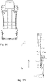
- die Vorrichtung gemäß einer bevorzugten Ausführungsform in einer Vorderansicht;
- Fig. 4A
- den Fahrzeugsitz in einer ersten Stellung;
- Fig. 4B
- den Fahrzeugsitz in einer nach hinten geneigten Stellung;
- Fig. 4C
- den Fahrzeugsitz in einer nach vorne geneigten Stellung;
- Fig. 5
- schematische Ansicht eines Adapterelements mit einem Bolzenelement;
- Fig. 6
- die Elemente, welche mit dem Sitzteil fest verbunden sind;
- Fig. 7
- die Elemente der
Figur 6 in einem montierten Zustand in einer Vorderansicht; - Fig. 8A-8H
- ein schematisches Vorgehen zum Herstellen einer Vorspannung der Spiralfeder;
- In den Figuren sind gleiche Bauteile jeweils mit den entsprechenden Bezugszeichen zu verstehen. Zur besseren Übersichtlichkeit können in manchen Figuren Bauteile nicht mit einem Bezugszeichen versehen sein, die jedoch an anderer Stelle bezeichnet worden sind.
- In den
Figuren 1A-1C werden verschiedene Bauteile einer Vorrichtung 1 gemäß einer besonders bevorzugten Ausführungsform gezeigt. Dabei zeigt dieFigur 1A ein Adapterelement 9, dieFigur 1B ein Bolzenelement 14 und dieFigur 1C ein Adaptergehäuse 17. - Erfindungsgemäß ist das Adapterelement 9 mit einer Neigungsverstellungseinrichtung 8 (hier nicht gezeigt) fest verbunden. Dazu weist vorzugsweise das Adapterelement 9 mindestens eine erste Verbindungsstelle 27 auf, die mit ersten komplementären Verbindungsstellen 27' (hier nicht gezeigt) verbindbar sind, insbesondere verschweißbar sind. Die Verbindungsstellen 27, 27' dienen insbesondere der Positionierung des Adapterelement 9 gegenüber der Neigungsverstellungseinrichtung 8. Das Adapterelement 9 ist durch die feste Verbindung zu der Neigungsverstellungseinrichtung 8 ebenfalls um die erste Drehachse 7 drehbar angeordnet.
- Weiter erfindungsgemäß weist das Adapterelement 9 eine erste Aussparung 11 auf, welche mit einer ersten Lasche 12 verbindbar ist. Vorzugsweise weist dabei die erste Aussparung 11 einen zentralen Bereich 30 sowie zumindest einen Seitenbereich 31 auf, vorliegend zwei Seitenbereiche 31. Der zentrale Bereich 30 ist hierbei in seinen Dimensionen derart ausgebildet, dass eine Breite 31 der Lasche 12 im Wesentlichen einer Breite 33 des zentralen Bereichs 30 entspricht. Darüber hinaus ist eine Höhe 35 der Aussparung 11 größer als eine Höhe 34 der Lasche 12.
- Die Aussparung 11 ist vorliegend im Wesentlichen trichterförmig bzw. in der Form eines Trichters 36 ausgebildet, wobei der zentrale Bereich 30 ist in einer Draufsicht auf das Adapterelement im Wesentlichen rechteckig ausgestaltet ist. Die Seitenbereiche 31 bilden dabei in einer Draufsicht des Adapterelements 9 die Schenkel eines Trapezes aus, wobei die kürzere Grundseite 37 des Trapezes eine Seite des Rechtecks des zentralen Bereichs 30 bildet.
- Weiter ist gemäß der
Figur 1A zu erkennen, dass das Adapterelement 9 einen ersten Bereich 23 und einen zweiten Bereich 24 aufweist, wobei sich der erste Bereich 23 in einer ersten Ebene und der zweite Bereich 24 in einer zweiten Ebene erstrecken, wobei die erste Ebene parallel zu der zweiten Ebene ausgebildet ist. - Weiter umfasst das Adapterelement 9 ein erstes Anschlagelement 21, welches mit dem zweiten Bereich 24 des Adapterelements 9 mit einem Anfangsbereich 39 verbunden ist und einen Mittelbereich 40 und einen Endbereich 41 aufweist. Insbesondere der Mittelbereich 40 erstreckt sich unter anderem in Richtung der ersten Drehachse 7 weg von dem zweiten Bereich 24. Der Mittelbereich 40 geht in einen Endbereich 41 über, welcher sich vorzugsweise in einer dritten Ebene erstreckt, wobei die dritte Ebene parallel zu der ersten Ebene ist und wobei die erste Ebene zwischen der dritten und der zweiten Ebene angeordnet ist.
- Weiter ist der
Figur 1A zu entnehmen, dass der erste Bereich 23 mindestens eine zweite Verbindungsstelle 28 aufweist, welche mit zweiten Verbindungsstellen 28' des ersten Bereichs 25 des Adaptergehäuses 17 mittels einer Verbindung, beispielsweise durch eine Schraubverbindung oder dergleichen, verbindbar sind. - Der
Figur 1B ist hierbei ein Bolzenelement 14 zu entnehmen, welches mit dem Adapterelement 9 durch einen Verbindungsabschnitt 43 fest verbunden werden kann, so dass das Bolzenelement 14 ebenfalls um die erste Drehachse 7 drehbar ist. Bevorzugt wird der Verbindungsabschnitt 43 mit dem Adapterelement 9 verschweißt. Weiter umfasst das Bolzenelement 14 einen Abschnitt, welcher zumindest einen flächig ausgebildeten Bereich 15 und einen kreisartigen Bereich 15' mit Durchmesser D' aufweist. Vorliegend sind zwei derartige flächige Bereiche 15 angeordnet. Weiter umfasst das Bolzenelement 14 einen zylinderförmigen Abschnitt 38, welcher sich an dem Abschnitt mit den flächigen Bereichen 15 anschließt. Der zylinderförmige Abschnitt 38 weist einen Durchmesser D auf, welcher einer Breite 44 einer zweiten Aussparung 44 entspricht. - Die zweite Aussparung 13 ist hierbei ähnlich zu der ersten Aussparung 11 ausgebildet, weist also ebenso einen zentralen Bereich auf, der vorliegend jedoch im Wesentlichen kreisförmig ausgebildet ist, und einen Trichter auf.
- Durch die trichterförmige Ausgestaltung kann einerseits die erste Aussparung 11 leichter mit der ersten Lasche 12 und andererseits die zweite Aussparung 13 leichter mit dem Bolzenelement 14 verbunden werden.
- Weiter weist das Bolzenelement einen Übergangsbereich 42 zwischen dem Abschnitt mit flächigen Bereichen 15 und dem zylinderförmigen Bereich 38 auf.
- Insbesondere beträgt der Durchmesser D des zylinderförmigen Bereichs 38 höchstens einen Abstand zwischen den vorliegend zwei parallel zueinander flächig ausgebildeten Bereichen 15 des Bolzenelements 14.
- Weiter umfasst das Adaptergehäuse 17 eine Adapterplatte 29, mittels welcher das Adaptergehäuse 17 mit der Rückenlehne 2 verbindbar ist.
- Der
Figur 2 ist hierbei eine Vorrichtung 1 gemäß einer bevorzugten Ausführungsform und eine Rückenlehne 2 sowie ein Sitzteil 3 zu entnehmen. Das Sitzteil 3 weist im seinem hinteren Bereich 4 insbesondere einen sich in Fahrzeugsitzhöhenrichtung H erstreckenden Abschnitt 45. Mit dem Sitzteil 3, vorliegend dem Abschnitt 45, ist eine Neigungsverstellungseinrichtung 8 fest mit dem Sitzteil 3 bzw. dem Abschnitt 45 verbunden. - Mit der Rückenlehne 2 ist das Adaptergehäuse 17 mittels der Adapterplatte 29 verbunden. Darüber hinaus ist an der Neigungsverstellungseinrichtung 8 das Adapterelement 9 angeordnet, wobei zumindest die ersten Verbindungsstellen 27 mit den ersten komplementären Verbindungsstellen 27' fest verbunden sind, so dass das Adapterelement 9 fest mit der Neigungsverstellungseinrichtung 8 verbunden ist.
- Mit dem Adapterelement 9 ist das Bolzenelement 14 fest verbunden, und mit dem Bolzenelement 14 ist eine Spiralfeder 18 verbunden, welche ein erstes Spiralfederende 19 und in zweites Spiralfederende 20 aufweist. Das erste Spiralfederende 19 ist dabei entsprechend dem Abschnitt mit flächigen Bereichen 15 des Bolzenelements 14 ausgebildet und derart dimensioniert, dass das erste Spiralfederende 19 den Abschnitt mit flächigen Bereichen 15 formschlüssig umschließt.
- Weiter sind das Adaptergehäuse 17 und das Adapterelement 9 durch Schrauben 46 miteinander verbunden. Insbesondere sind auch noch weitere lösbare Verbindungen denkbar, so dass die Rückenlehne 2 leicht und schnell wieder von dem Sitzteil 3 gelöst werden kann.
- Zusätzlich weist das Sitzteil 3 noch ein zweites Anschlagelement 22 auf.
- Das Adaptergehäuse 17 mit der ersten Lasche 12 und der zweiten Aussparung 13 sind als eine erste Baugruppe 50 mit der Rückenlehne 2 verbunden, die Neigungsverstellungseinrichtung 8, das Adapterelement 9 und das Bolzenelement sind als eine zweite Baugruppe 51 mit dem Sitzteil 3 verbunden.
- Durch die Anordnung und Ausgestaltung der ersten 11 und zweien Aussparung 13, der ersten Lasche 12 und dem Bolzenelement 14 zueinander können, wie in den
Figuren 3A- 3D , das Sitzteil 3 und die Rückenlehne 2 leicht miteinander verbunden werden, so dass ein Verschrauben oder dergleichen ohne größere Anstrengung möglich ist. - Wie insbesondere den
Figuren 3A und3C zu entnehmen ist, sind zwei erste Baugruppen 50 und zwei zweite Baugruppen 51 vorgesehen. Zwischen der ersten Baugruppe 50 und der zweiten Baugruppe 51 ist eine Spiralfeder 18 angeordnet, die je nach Stellung der Rückenlehne gespannt ist oder nicht. Die Funktionsweise der Spiralfeder 18 wird nachfolgend in Verbindung mit nachfolgenden Figuren genauer beschrieben. - Der
Figur 3D ist die Lage der ersten 47, der zweiten 48 und der dritten Ebene 49 zueinander gezeigt. Wie weiter zu erkennen ist, erstreckt sich auch der erste Bereich 25 des Adaptergehäuses 17 in der ersten Ebene 47. - Ähnlich wie die erste Aussparung 11 ist auch der erste Anschlag 21 mit einem bestimmten dritten Winkel 52 gegenüber der Rückenlehnenlängsrichtung RL angeordnet. Der zweite Anschlag 22, welcher ortsfest gegenüber dem Sitzteil 3 angeordnet ist, ist mit einem konstanten vierten Winkel 53 gegenüber der Fahrzeugsitzhöhenrichtung H angeordnet.
- Wird die Rückenlehne 2 um die erste Drehachse 7 gedreht, so verändert sich der Winkel zwischen Rückenlehnenlängsrichtung RL und Fahrzeugsitzhöhenrichtung ständig. Es kann daher vorkommen, dass, in einer radialen Richtung von der ersten Drehachse 7 weg gesehen, das erste 21 und das zweite Anschlagelement 22 auf einer gemeinsamen radialen Strecke angeordnet sind. Die Spiralfeder 19 weist hierbei eine gewisse Vorspannung auf.
- In diesem Fall des Übereinstimmens von dem ersten 21 und dem zweiten Anschlagelement 22 steht die Spiralfeder 19, insbesondere dem zweiten Spiralfederende 20, sowohl mit dem ersten 21 als auch dem zweiten Anschlagelement 22 in Wirkkontakt. Wird die Rückenlehne 2 nun in Fahrzeugsitzlängsrichtung L weiter nach vorne gedreht, so wird das erste Anschlagelement 21 entsprechend mitgedreht und ebenfalls das zweite Spiralfederende 20. Dadurch bleibt das zweite Spiralfederende 20 weiterhin mit dem ersten Anschlagelement 21 in Kontakt und es wird gleichzeitig der Kontakt zwischen dem zweiten Spiralfederende 20 und dem zweiten Anschlagelement 22 gelöst.
- Dadurch, dass das erste Spiralfederende 20 mittels des Bolzenelements 14 ortsfest gegenüber dem Adapterelement 9 angeordnet ist und ebenso das erste Anschlagelement 21 ortsfest an dem Adapterelement 9 angeordnet ist, wird die Vorspannung der Spiralfeder nicht geändert, so dass ohne Kraft aufzuwenden die Rückenlehne 2 nach vorne geklappt werden kann.
- Wird hingegen die Rückenlehne 2 in Fahrzeugsitzlängsrichtung L nach hinten bewegt, so ändert sich die Situation. Das zweite Spiralfederende 20 steht weiterhin mit dem zweiten Anschlagelement 22 in Wirkkontakt und das erste Anschlagelement 21 wird von dem zweiten Spiralfederende 20 weg bewegt. Wird das Adapterelement 9 mit der Spiralfeder 19 weiter um die erste Drehachse 7 nach hinten gedreht, so wird die Vorspannung der Spiralfeder 19 weiter geändert, da das erste Spiralfederende 19 entsprechend dem Adapterelement 9 bewegt wird und das zweite Spiralfederende 20 weiterhin mit dem zweiten Anschlagelement 22 in Kontakt steht.
- Die
Figuren 4A bis 4C zeigen die verschiedenen Stellungen der Rückenlehne 2 gegenüber dem Sitzteil 3 und die Spiralfeder 19 in den Stellungen. - Die
Figur 4A zeigt die Spiralfeder 19 in Kontakt mit dem ersten 21 und dem zweiten Anschlagelement 22. Die Rückenlehne 2 ist in dieser Situation nach vorne geneigt, so dass die Rückenlehenlängsrichtung RL einen fünften Winkel mit der Fahrzeugsitzlängsrichtung L einschließt, vorzugsweise einen Winkel von etwa 80°. Es sind aber natürlich auch andere fünfte Winkel denkbar, wobei diese von dem zweiten Winkel 16, dem dritten Winkel 52 und dem vierten Winkel 53 abhängen. - Die
Figur 4B zeigt die Situation mit einer in Fahrzeugsitzlängsrichtung L nach hinten gedrehten Rückenlehne 2. Wie zu erkennen ist, ist die Spiralfeder 19, insbesondere das zweite Spiralfederende 20, mit dem zweiten Anschlagelement 22 in Wirkkontakt, das erste Anschlagelement 21 wurde entsprechend dem Adapterelement 9 mit nach hinten gedreht. Dadurch, dass das erste Spiralfederende 19 ebenfalls nach hinten gedreht wird, wird die Federspannung der Spiralfeder 19 verändert, so dass beim nach hinten bewegen der Rückenlehne 2 Kraft aufgewendet werden muss. - Die
Figur 4C zeigt die Situation mit einer nach vorne gedrehten Rückenlehne 2, so dass die Rückenlehnenlängsrichtung RL der Fahrzeugsitzlängsrichtung L entspricht. Wie zu erkennen ist, steht das zweite Spiralfederende 20 ausschließlich mit dem ersten Anschlagelement 21 in Wirkkontakt. Es ist daher keine zusätzliche Kraft notwendig, die Rückenlehne 2 nach vorne zu drehen. - Die
Figur 5 zeigt dabei eine schematische Übersicht über den ersten 10, zweiten 16, dritten 52 und vierten Winkel 53. Die Rückenlehnenlängsrichtung RL entspricht dabei der Haupterstreckungsrichtung der Rückenlehne 2, welche bei einer Drehung des Adapterelements 9 ebenso um die erste Drehachse 7 gedreht wird. - Die
Figur 6 zeigt insbesondere die Bauelemente der Vorrichtung 1, welche mit dem Sitzteil 3 fest verbunden sind, vorliegend die Neigungsverstellungseinrichtung 8, das Adapterelement 9 und das Bolzenelement 14, wobei das Bolzenelement 14 fest mit dem Adapterelement 9 und das Adapterelement 9 fest mit der Neigungsverstellungseinrichtung 8 verbunden ist. Weiter ist das zweite Anschlagelement 22 zu erkennen, welches ebenfalls fest mit dem Sitzteil 3 verbunden ist. Vorzugsweise handelt es sich bei der festen Verbindung um eine Schweißverbindung. - Wie weiter zu erkennen ist, weist das zweite Anschlagelement 22 einen Verbreiterungsbereich 58 auf, welcher sich in axialer Richtung der Drehachse 7 in Längsrichtung L von vorne nach hinten stetig verbreitert.
- Dabei weist das zweite Anschlagelement 22 einen zweiten Anschlagsbereich 49 auf, welcher sich senkrecht zu der ersten Drehachse 7 und in axialer Richtung der Drehachse 7 erstreckt.
- Die Elemente der
Figur 6 sind in derFigur 7 in einem zusammengebauten Zustand in einer Vorderansicht zu sehen. Wie insbesondere zu erkennen ist, ist die axiale Erstreckung 54 des ersten Anschlagelements 21, insbesondere des ersten Anschlagbereichs 55, kleiner als die axiale Erstreckung 56 des zweiten Anschlagelements 22, insbesondere des zweiten Anschlagbereichs 49. - Wird die Rückenlehne 2 um die erste Drehachse 7 gedreht, so verändert sich der Winkel zwischen Rückenlehnenlängsrichtung RL und Fahrzeugsitzlängsrichtung L ständig. Es kann daher vorkommen, dass, in einer Richtung senkrecht zu der ersten Drehachse 7 gesehen, das erste 21 und das zweite Anschlagelement 22 auf einer gemeinsamen Strecke angeordnet sind. Die Spiralfeder 18 weist hierbei eine gewisse Vorspannung auf, wobei es jedoch auch denkbar ist, dass die Spiralfeder 18 keine Vorspannung aufweist.
- In diesem Fall des Übereinstimmens von dem ersten 21 und dem zweiten Anschlagelement 22 steht die Spiralfeder 19, insbesondere dem zweiten Spiralfederende 20, sowohl mit dem ersten 21 als auch dem zweiten Anschlagelement 22 in Wirkkontakt. Wird die Rückenlehne 2 nun in Fahrzeugsitzlängsrichtung L weiter nach vorne gedreht, so wird das erste Anschlagelement 21 entsprechend mitgedreht und ebenfalls das zweite Spiralfederende 20. Dadurch bleibt das zweite Spiralfederende 20 weiterhin mit dem ersten Anschlagelement 21 in Kontakt und es wird gleichzeitig der Kontakt zwischen dem zweiten Spiralfederende 20 und dem zweiten Anschlagelement 22 gelöst.
- Dadurch, dass das erste Spiralfederende 20 mittels des Bolzenelements 14 ortsfest gegenüber dem Adapterelement 9 angeordnet ist und ebenso das erste Anschlagelement 21 ortsfest an dem Adapterelement 9 angeordnet ist, wird die Vorspannung der Spiralfeder nicht geändert, so dass ohne Kraft aufzuwenden die Rückenlehne 2 nach vorne geklappt werden kann.
- Wird hingegen die Rückenlehne 2 in Fahrzeugsitzlängsrichtung L nach hinten bewegt, so ändert sich die Situation. Das zweite Spiralfederende 20 steht weiterhin mit dem zweiten Anschlagelement 22 in Wirkkontakt und das erste Anschlagelement 21 wird von dem zweiten Spiralfederende 20 weg bewegt. Wird das Adapterelement 9 mit der Spiralfeder 19 weiter um die erste Drehachse 7 nach hinten gedreht, so wird die Vorspannung der Spiralfeder 19 weiter geändert, da das erste Spiralfederende 19 entsprechend dem Adapterelement 9 bewegt wird und das zweite Spiralfederende 20 weiterhin mit dem zweiten Anschlagelement 22 in Kontakt steht.
- Gemäß einer Ausführungsform weist die Spiralfeder 18 eine Vorspannung auf, entsprechend der Positionen des ersten 19 und zweiten Spiralfederende 20, insbesondere des zweiten Spiralfederendes 20 gegenüber den Anschlagelementen 21, 22. Die grundlegende Vorspannung der Spiralfeder 18 ist hierbei vorgegeben durch den Wirkkontakt des zweiten Spiralfederendes mit dem zweiten Anschlagelement 22, da zumindest immer diese Vorspannung vorliegt, wie bereits weiter oben beschrieben. Bei einer Drehung der Rückenlehne 2 in Fahrzeugsitzlängsrichtung L nach vorne herrscht weiter die grundlegende Vorspannung vor, wohingegen bei einer Drehung der Rückenlehne 2 nach hinten die Vorspannung verändert wird bei Drehung der Rückenlehne 2.
- Es ist jedoch bei Montage der Vorrichtung 1 bzw. des Fahrzeugsitzes 2 nicht vorteilhaft, eine Vorspannung der Spiralfeder durch einen Arbeiter einstellen zu lassen, da dies eine nicht unerhebliche Gefahr für den Arbeiter darstellen kann.
- Bei der Montage wird daher zur Einstellung der Vorspannung der Spiralfeder 18 ein einmaliger Montageschritt ausgeführt, welcher in seinen Einzelschritten nachfolgend detaillierter beschrieben wird.
- In einem ersten Schritt S1, dargestellt in der
Figur 8A , sind die jeweiligen Bauteile entsprechend an der Rückenlehne 2 bzw. dem Sitzteil 3 angebracht. Dabei ist das Adaptergehäuse 17 mit der Rückenlehne 2 fest verbunden und die Neigungsverstellungseinrichtung 8, das Adapterelement 9 und das Bolzenelement 14 mit dem Sitzteil 3 fest verbunden. Ebenso ist das zweite Anschlagelement 22 fest mit dem Sitzteil 3 verbunden. - In einem zweiten Schritt S2, dargestellt in der
Figur 8B , wird die Spiralfeder 18 auf das Bolzenelement 14 aufgesteckt, so dass das erste Spiralfederende 19 ortsfest mit dem Bolzenelement 14 verbunden ist, weist jedoch noch einen Freiheitsgrad in axialer Richtung der ersten Drehachse 7 auf. Wie zu erkennen ist, ist das zweite Spiralfederende 20 noch weder mit dem ersten 21 noch mit dem zweiten Anschlagelement 22 in Wirkkontakt. Insbesondere ist das zweite Spiralfederende 20 in Längsrichtung L gesehen vor dem ersten 21 und dem zweiten Anschlagelement 22 angeordnet, wobei das zweite Anschlagelement 22 vor dem ersten Anschlagelement 21 angeordnet ist. - In einem dritten Schritt S3, dargestellt in
Figur 8C , wird das Adaptergehäuse 17 mit dem Adapterelement 9 verschraubt durch Schrauben 46 und der Freiheitsgrad der Spiralfeder 18 in axialer Richtung entfernt. - In der
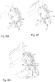
Figur 8D wird ein vierter Schritt S4 gezeigt, in welchem die Rückenlehne 2 in Fahrzeugsitzlängsrichtung L nach vorne gedreht wird. Durch die Ausgestaltung des zweiten Anschlagelements 22 mit dem Verbreiterungsbereich 58 wird das zweite Spiralfederende 20 an dem Verbreiterungsbereich 58 solange zwangsgeführt, bis das zweite Spiralfederende 20 das zweite Anschlagelement 22, insbesondere den zweiten Anschlagbereich 57, übersprungen hat, wie in derFigur 8E dargestellt. Somit wurde die grundlegende Vorspannung der Spiralfeder 18 eingestellt. Jedoch befindet sich das zweite Spiralfederende 19 nun zwischen dem ersten 21 und dem zweiten Anschlagelement 22, so dass bisher nur ein Wirkkontakt des zweiten Spiralfederendes 20 mit dem zweiten Anschlagelement 22 möglich ist. Um einen Wirkkontakt mit dem ersten Anschlagelement 21 zu ermöglichen, ist es notwendig, dass zweite Spiralfederende 20 in Längsrichtung L gesehen sowohl hinter dem ersten 21 als auch dem zweiten Anschlagelement 22 angeordnet ist. - Dies wird in einem Schritt S5, dargestellt in den
Figuren 8F und 8G , hergestellt, indem die Rückenlehne 2 in Längsrichtung L gesehen wieder nach hinten gedreht wird. Da im Schritt S4 das zweite Spiralfederende 20 zwischen dem ersten 21 und dem zweiten Anschlagelement 22 angeordnet ist, wird durch Drehung der Rückenlehne 2 nach hinten das erste Anschlagelement 21 nach vorne bewegt. Durch die Ausgestaltung des ersten Anschlagelements 21, insbesondere des Mittelbereichs 40, welcher ähnlich dem Verbreiterungsbereich 58 ausgebildet ist. Da sich das zweite Anschlagelement 22 in axialer Richtung weiter erstreckt als das erste Anschlagelement 21, wird das zweite Spiralfederende 20 durchgehend von dem zweiten Anschlagelement gehalten. Das zweite Spiralfederende 20 bewegt sich zwangsführt an dem Mittelbereich 40 und überspringt auch das erste Anschlagelement 21. - In einem abschließenden Schritt S6, dargestellt in der
Figur 8H , wird die Rückenlehne in eine Position gebracht, in welcher die Rückenlehnenlängsrichtung RL und die Fahrzeugsitzlängsrichtung L einen Winkel von 90° aufweisen. Der Winkel zwischen der ersten Richtung 48 und der zweiten Richtung 50 ist dabei größer als 0°, vorzugsweise 10°. - Sämtliche in den Anmeldungsunterlagen offenbarten Merkmale werden als erfindungswesentlich beansprucht, sofern sie einzeln oder in Kombination gegenüber dem Stand der Technik neu sind.
-
- 1
- Vorrichtung
- 2
- Rückenlehne
- 3
- Sitzteil
- 4
- hinterer Bereich des Sitzteils
- 5
- unterer Bereich der Rückenlehne
- 6
- Fahrzeugsitz
- 7
- erste Drehachse
- 8
- Neigungsverstellungseinrichtung
- 9
- Adapterelement
- 10
- erster Winkel
- 11
- Aussparung
- 12
- erste Lasche
- 13
- zweite Aussparung
- 14
- Bolzenelement
- 15
- flächig ausgebildeter Bereich
- 16
- zweiter Winkel
- 17
- Adaptergehäuse
- 18
- Spiralfeder
- 19
- erstes Spiralfederende
- 20
- zweites Spiralfederende
- 21
- erstes Anschlagelement
- 22
- zweites Anschlagelement
- 23
- erster Bereich des Adapterelements
- 24
- zweiter Bereich des Adapterelements
- 25
- erster Bereich Adaptergehäuse
- 26
- zweiter Bereich Adaptergehäuse
- 27
- erste Verbindungsstelle
- 27'
- erste komplementäre Verbindungsstelle
- 28, 28'
- zweite Verbindungsstelle
- 29
- Adapterplatte
- 30
- zentraler Bereich
- 31
- Seitenbereich
- 32
- Breite Lasche
- 33
- Breite zentraler Bereich
- 34
- Höhe Lasche
- 35
- Höhe zentraler Bereich
- 36
- Trichter
- 37
- kurze Grundseite
- 38
- zylindrischer Abschnitt
- 39
- Anfangsbereich
- 40
- Mittelbereich
- 41
- Endbereich
- 42
- Übergangsbereich
- 43
- Verbindungsabschnitt
- 44
- Breite zweite Aussparung
- 45
- nach oben erstreckender Abschnitt
- 46
- Schraube
- 47
- erste Ebene
- 48
- zweite Ebene
- 49
- dritte Ebene
- 50
- erste Baugruppe
- 51
- zweite Baugruppe
- 52
- dritter Winkel
- 53
- vierter Winkel54 axiale Erstreckung
- 55
- erster Anschlagbereich
- 56
- axiale Erstreckung
- 57
- zweiter Anschlagbereich
- 58
- Verbreiterungsbereich
Claims (10)
- Vorrichtung zum Verbinden eines in Fahrzeugsitzhöhenrichtung gesehenen unteren Bereichs einer Rückenlehne mit einem in Fahrzeugsitzlängsrichtung gesehenen hinteren Bereich eines Sitzteils eines Fahrzeugsitzes, wobei eine um eine in Fahrzeugsitzbreitenrichtung verlaufende erste Drehachse drehbare Neigungsverstellungseinrichtung zum Einstellen einer Neigung der Rückenlehne relativ zum Sitzteil mit dem Sitzteil verbunden ist,
dadurch gekennzeichnet, dass
die Vorrichtung ein mit der Neigungsverstellungseinrichtung fest verbundenes und um die erste Drehachse drehbares Adapterelement umfasst, welches eine sich in einem ersten Winkel zu einer Rückenlehnenlängsrichtung erstreckende erste Aussparung aufweist, wobei die erste Aussparung mit einer an der Rückenlehne angeordneten und komplementär zu der ersten Aussparung ausgebildeten ersten Lasche verbindbar ist. - Vorrichtung gemäß Anspruch 1,
dadurch gekennzeichnet, dass
die Rückenlehne eine zweite Aussparung aufweist, welche mit einem mit dem Adapterelement fest verbundenen Bolzenelement, welches um die erste Drehachse drehbar angeordnet ist, in Wirkkontakt bringbar ist. - Vorrichtung gemäß Anspruch 2,
dadurch gekennzeichnet, dass
das Bolzenelement mindestens einen flächig ausgebildeten Bereich umfasst, welcher in Fahrzeugsitzbreitenrichtung gesehen einen zweiten Winkel mit der Rückenlehnenlängsrichtung einschließt. - Vorrichtung nach einem der vorangegangenen Ansprüche,
dadurch gekennzeichnet, dass
an der Rückenlehne ein Adaptergehäuse angeordnet ist, welches die Lasche und die zweite Aussparung aufweist, wobei das Adaptergehäuse mit dem Adapterelement verbindbar ist. - Vorrichtung nach einem der vorangegangenen Ansprüche,
dadurch gekennzeichnet, dass
in Fahrzeugsitzbreitenrichtung gesehen das Adapterelement zwischen der Rückenlehne und dem Sitzteil angeordnet ist, wobei zwischen dem Adapterelement und dem Sitzteil die Neigungsverstellungseinrichtung angeordnet ist. - Vorrichtung nach Anspruch 2 oder 3,
dadurch gekennzeichnet, dass
die Vorrichtung eine Spiralfeder aufweist, welche mit einem ersten Spiralfederende mit dem Bolzenelement verbunden ist, wobei das zweite Spiralfederende mit einem ersten Anschlagelement des Adapterelements und/oder mit einem zweiten Anschlagelement des Sitzteils wechselwirkt. - Vorrichtung nach Anspruch 6,
dadurch gekennzeichnet, dass
die Spiralfeder zwischen der Rückenlehne und dem Adapterelement angeordnet ist. - Vorrichtung nach einem der vorangegangen Ansprüche,
dadurch gekennzeichnet, dass
das Adapterelement einen ersten und einen zweiten Bereich aufweist, wobei der erste Bereich in einer ersten Ebene und der zweite Bereich in einer zweiten Ebene angeordnet sind, wobei die erste Ebene und die zweite Ebene parallel zueinander ausgebildet sind. - Vorrichtung nach einem der vorangegangenen Ansprüche,
dadurch gekennzeichnet, dass
der erste Winkel entweder 0° oder 180° beträgt. - Verfahren zum Verbinden eines in Fahrzeugsitzhöhenrichtung gesehenen unteren Bereichs einer Rückenlehne mit einem in Fahrzeugsitzlängsrichtung gesehenen hinteren Bereich eines Sitzteils eines Fahrzeugsitzes, wobei eine um eine in Fahrzeugsitzbreitenrichtung verlaufende erste Drehachse drehbare Neigungsverstellungseinrichtung zum Einstellen einer Neigung der Rückenlehne relativ zum Sitzteil mit dem Sitzteil verbunden ist,
dadurch gekennzeichnet, dass
die Vorrichtung ein mit der Neigungsverstellungseinrichtung fest verbundenes und um die erste Drehachse drehbares Adapterelement umfasst, welches eine sich in einem ersten Winkel zu einer Rückenlehnenlängsrichtung erstreckende erste Aussparung aufweist, wobei die erste Aussparung mit einer an der Rückenlehne angeordneten und komplementär zu der ersten Aussparung ausgebildeten ersten Lasche verbunden wird.
Applications Claiming Priority (1)
| Application Number | Priority Date | Filing Date | Title |
|---|---|---|---|
| DE102016115266.8A DE102016115266B4 (de) | 2016-08-17 | 2016-08-17 | Vorrichtung mit Adapterelement und Verfahren zum Verbinden |
Publications (2)
| Publication Number | Publication Date |
|---|---|
| EP3287314A1 true EP3287314A1 (de) | 2018-02-28 |
| EP3287314B1 EP3287314B1 (de) | 2020-03-04 |
Family
ID=59315490
Family Applications (1)
| Application Number | Title | Priority Date | Filing Date |
|---|---|---|---|
| EP17180731.6A Active EP3287314B1 (de) | 2016-08-17 | 2017-07-11 | Fahrzeugsitz mit vorrichtung |
Country Status (4)
| Country | Link |
|---|---|
| US (1) | US10513207B2 (de) |
| EP (1) | EP3287314B1 (de) |
| CN (1) | CN107757432B (de) |
| DE (1) | DE102016115266B4 (de) |
Cited By (1)
| Publication number | Priority date | Publication date | Assignee | Title |
|---|---|---|---|---|
| WO2025072706A1 (en) * | 2023-09-29 | 2025-04-03 | Permobil, Inc. | Caster adjustment assembly for a wheelchair |
Families Citing this family (3)
| Publication number | Priority date | Publication date | Assignee | Title |
|---|---|---|---|---|
| JP6874360B2 (ja) * | 2016-12-21 | 2021-05-19 | トヨタ紡織株式会社 | 乗物用シート |
| US10668843B2 (en) * | 2018-06-25 | 2020-06-02 | Faurecia Automotive Seating, Llc | Fastening device for a vehicle seat bottom |
| DE102020112459A1 (de) * | 2020-05-07 | 2021-11-11 | Faurecia Autositze Gmbh | Fahrzeugsitzbeschlag und Fahrzeugsitz |
Citations (3)
| Publication number | Priority date | Publication date | Assignee | Title |
|---|---|---|---|---|
| US5263763A (en) * | 1993-01-25 | 1993-11-23 | Saturn Corporation | Vehicle seat mounting bracket |
| FR2842476A1 (fr) * | 2002-07-18 | 2004-01-23 | Faurecia Sieges Automobile | Systeme de liaison d'un dossier pivotant sur une assise de siege de vehicule automobile, et siege pourvu d'un tel systeme de liaison |
| DE102014220405A1 (de) * | 2014-10-08 | 2016-04-14 | Johnson Controls Components Gmbh & Co. Kg | Verstellvorrichtung für eine Rücksitzbank und Sitzanordnung |
Family Cites Families (10)
| Publication number | Priority date | Publication date | Assignee | Title |
|---|---|---|---|---|
| AUPO877397A0 (en) * | 1997-08-26 | 1997-09-18 | Henderson's Industries Pty Ltd | Seat backrest mounting |
| WO2003022622A1 (de) * | 2001-09-06 | 2003-03-20 | Keiper Gmbh & Co. | Beschlag für einen fahrzeugsitz |
| JP2007038852A (ja) * | 2005-08-03 | 2007-02-15 | Aisin Seiki Co Ltd | 車両用シート装置 |
| DE102008023943B4 (de) * | 2008-05-13 | 2012-03-15 | Keiper Gmbh & Co. Kg | Fahrzeugsitz mit Beschlägen |
| CN102037461A (zh) * | 2008-08-15 | 2011-04-27 | 李尔公司 | 交通工具座椅和倾斜存储器模块 |
| JP5625831B2 (ja) * | 2010-12-01 | 2014-11-19 | アイシン精機株式会社 | シートフレーム |
| CN203410325U (zh) * | 2013-07-29 | 2014-01-29 | 江苏力乐汽车部件股份有限公司 | 一种带有核心元件的汽车座椅调角器 |
| CN203805735U (zh) * | 2014-03-28 | 2014-09-03 | 上海延锋江森座椅有限公司 | 一种后排座椅靠背调角器的解锁手柄机构 |
| DE102015009094B4 (de) * | 2015-07-17 | 2020-07-09 | Faurecia Autositze Gmbh | Verstellbarer Fahrzeugsitz |
| CN204956166U (zh) * | 2015-08-27 | 2016-01-13 | 江苏力乐汽车部件股份有限公司 | 双联动式角度可调机构 |
-
2016
- 2016-08-17 DE DE102016115266.8A patent/DE102016115266B4/de active Active
-
2017
- 2017-07-11 EP EP17180731.6A patent/EP3287314B1/de active Active
- 2017-08-02 US US15/666,992 patent/US10513207B2/en active Active
- 2017-08-04 CN CN201710658589.8A patent/CN107757432B/zh active Active
Patent Citations (3)
| Publication number | Priority date | Publication date | Assignee | Title |
|---|---|---|---|---|
| US5263763A (en) * | 1993-01-25 | 1993-11-23 | Saturn Corporation | Vehicle seat mounting bracket |
| FR2842476A1 (fr) * | 2002-07-18 | 2004-01-23 | Faurecia Sieges Automobile | Systeme de liaison d'un dossier pivotant sur une assise de siege de vehicule automobile, et siege pourvu d'un tel systeme de liaison |
| DE102014220405A1 (de) * | 2014-10-08 | 2016-04-14 | Johnson Controls Components Gmbh & Co. Kg | Verstellvorrichtung für eine Rücksitzbank und Sitzanordnung |
Cited By (2)
| Publication number | Priority date | Publication date | Assignee | Title |
|---|---|---|---|---|
| WO2025072706A1 (en) * | 2023-09-29 | 2025-04-03 | Permobil, Inc. | Caster adjustment assembly for a wheelchair |
| US12420587B2 (en) | 2023-09-29 | 2025-09-23 | Permobil, Inc. | Caster adjustment assembly for a wheelchair |
Also Published As
| Publication number | Publication date |
|---|---|
| DE102016115266A1 (de) | 2018-02-22 |
| EP3287314B1 (de) | 2020-03-04 |
| DE102016115266B4 (de) | 2021-05-12 |
| US10513207B2 (en) | 2019-12-24 |
| CN107757432A (zh) | 2018-03-06 |
| CN107757432B (zh) | 2019-11-05 |
| US20180050618A1 (en) | 2018-02-22 |
Similar Documents
| Publication | Publication Date | Title |
|---|---|---|
| DE102014200933B4 (de) | Lenksäule | |
| EP3287314B1 (de) | Fahrzeugsitz mit vorrichtung | |
| DE102014000522A1 (de) | Bewegungseinrichtung für einen Flugzeugsitz | |
| EP2710616B1 (de) | Überspannungsableiter | |
| CH713677A2 (de) | Anlenkungseinrichtung für eine Kupplung, insbesondere eines Schienenfahrzeugs. | |
| DE102013014966A1 (de) | Lenksäule für ein Fahrzeug | |
| DE102016112119A1 (de) | Federungsvorrichtung | |
| AT516100A1 (de) | Einstellsystem für einen Fahrzeugscheinwerfer sowie Fahrzeugscheinwerfer | |
| WO2006082024A1 (de) | Wägesystem | |
| WO2013117429A2 (de) | Luftfederbefestigung | |
| DE202018102171U1 (de) | Sensorhalter und Vorrichtung mit einem solchen Sensorhalter | |
| DE10217534A1 (de) | Verriegelungseinrichtung von Einstelleinrichtungen für Lenksäulen von Kraftfahrzeugen | |
| DE10316190A1 (de) | Klemmvorrichtung zur Lagefixierung einer Lenksäule | |
| DE102011089015A1 (de) | Verbindungsanordnung für Karosseriebauteile eines Fahrzeugs | |
| EP3287313B1 (de) | Vorrichtung zum einstellen einer rückenlehnenneigung | |
| DE202010012472U1 (de) | Gurthöheneinstellvorrichtung sowie Fahrzeugsitz mit einer solchen | |
| EP3501889A1 (de) | Fahrzeugsitz und längshorizontalfederung | |
| EP3825175B1 (de) | Fahrzeugsitz | |
| DE102023115519A1 (de) | Lagereinrichtung, Führungsanordnung sowie Ausstattungsteil eines Fahrzeuginnenraums | |
| EP1901953B1 (de) | Klemmvorrichtung für eine lenksäule | |
| EP1848971A1 (de) | W[gesystem | |
| DE202007015012U1 (de) | Schutzwandanordnung zum Begrenzen und Absichern von Fahrbahnen, insbesondere in Baustellenbereichen | |
| DE102018128237B4 (de) | Befestigungs- und Einstellvorrichtung für eine Lampe | |
| DE102023119171A1 (de) | Längsverstelleinrichtung mit Abweiserkonzept für Fahrzeugsitz | |
| DE102016006873A1 (de) | Verriegelungseinrichtung für eine Kopfstütze einer Fahrzeugsitzanlage |
Legal Events
| Date | Code | Title | Description |
|---|---|---|---|
| PUAI | Public reference made under article 153(3) epc to a published international application that has entered the european phase |
Free format text: ORIGINAL CODE: 0009012 |
|
| STAA | Information on the status of an ep patent application or granted ep patent |
Free format text: STATUS: THE APPLICATION HAS BEEN PUBLISHED |
|
| AK | Designated contracting states |
Kind code of ref document: A1 Designated state(s): AL AT BE BG CH CY CZ DE DK EE ES FI FR GB GR HR HU IE IS IT LI LT LU LV MC MK MT NL NO PL PT RO RS SE SI SK SM TR |
|
| AX | Request for extension of the european patent |
Extension state: BA ME |
|
| STAA | Information on the status of an ep patent application or granted ep patent |
Free format text: STATUS: REQUEST FOR EXAMINATION WAS MADE |
|
| 17P | Request for examination filed |
Effective date: 20180731 |
|
| RBV | Designated contracting states (corrected) |
Designated state(s): AL AT BE BG CH CY CZ DE DK EE ES FI FR GB GR HR HU IE IS IT LI LT LU LV MC MK MT NL NO PL PT RO RS SE SI SK SM TR |
|
| REG | Reference to a national code |
Ref country code: DE Ref legal event code: R079 Ref document number: 502017004055 Country of ref document: DE Free format text: PREVIOUS MAIN CLASS: B60N0002235000 Ipc: B60N0002220000 |
|
| RIC1 | Information provided on ipc code assigned before grant |
Ipc: B60N 2/225 20060101ALI20190503BHEP Ipc: B60N 2/235 20060101ALI20190503BHEP Ipc: B60N 2/68 20060101ALI20190503BHEP Ipc: B60N 2/22 20060101AFI20190503BHEP Ipc: B60N 2/30 20060101ALI20190503BHEP |
|
| GRAP | Despatch of communication of intention to grant a patent |
Free format text: ORIGINAL CODE: EPIDOSNIGR1 |
|
| STAA | Information on the status of an ep patent application or granted ep patent |
Free format text: STATUS: GRANT OF PATENT IS INTENDED |
|
| INTG | Intention to grant announced |
Effective date: 20190624 |
|
| GRAJ | Information related to disapproval of communication of intention to grant by the applicant or resumption of examination proceedings by the epo deleted |
Free format text: ORIGINAL CODE: EPIDOSDIGR1 |
|
| STAA | Information on the status of an ep patent application or granted ep patent |
Free format text: STATUS: REQUEST FOR EXAMINATION WAS MADE |
|
| INTC | Intention to grant announced (deleted) | ||
| GRAP | Despatch of communication of intention to grant a patent |
Free format text: ORIGINAL CODE: EPIDOSNIGR1 |
|
| STAA | Information on the status of an ep patent application or granted ep patent |
Free format text: STATUS: GRANT OF PATENT IS INTENDED |
|
| INTG | Intention to grant announced |
Effective date: 20191009 |
|
| GRAS | Grant fee paid |
Free format text: ORIGINAL CODE: EPIDOSNIGR3 |
|
| GRAA | (expected) grant |
Free format text: ORIGINAL CODE: 0009210 |
|
| STAA | Information on the status of an ep patent application or granted ep patent |
Free format text: STATUS: THE PATENT HAS BEEN GRANTED |
|
| AK | Designated contracting states |
Kind code of ref document: B1 Designated state(s): AL AT BE BG CH CY CZ DE DK EE ES FI FR GB GR HR HU IE IS IT LI LT LU LV MC MK MT NL NO PL PT RO RS SE SI SK SM TR |
|
| REG | Reference to a national code |
Ref country code: GB Ref legal event code: FG4D Free format text: NOT ENGLISH |
|
| REG | Reference to a national code |
Ref country code: CH Ref legal event code: EP |
|
| REG | Reference to a national code |
Ref country code: AT Ref legal event code: REF Ref document number: 1239991 Country of ref document: AT Kind code of ref document: T Effective date: 20200315 |
|
| REG | Reference to a national code |
Ref country code: DE Ref legal event code: R096 Ref document number: 502017004055 Country of ref document: DE |
|
| REG | Reference to a national code |
Ref country code: IE Ref legal event code: FG4D Free format text: LANGUAGE OF EP DOCUMENT: GERMAN |
|
| PG25 | Lapsed in a contracting state [announced via postgrant information from national office to epo] |
Ref country code: NO Free format text: LAPSE BECAUSE OF FAILURE TO SUBMIT A TRANSLATION OF THE DESCRIPTION OR TO PAY THE FEE WITHIN THE PRESCRIBED TIME-LIMIT Effective date: 20200604 Ref country code: FI Free format text: LAPSE BECAUSE OF FAILURE TO SUBMIT A TRANSLATION OF THE DESCRIPTION OR TO PAY THE FEE WITHIN THE PRESCRIBED TIME-LIMIT Effective date: 20200304 Ref country code: RS Free format text: LAPSE BECAUSE OF FAILURE TO SUBMIT A TRANSLATION OF THE DESCRIPTION OR TO PAY THE FEE WITHIN THE PRESCRIBED TIME-LIMIT Effective date: 20200304 |
|
| REG | Reference to a national code |
Ref country code: NL Ref legal event code: MP Effective date: 20200304 |
|
| PG25 | Lapsed in a contracting state [announced via postgrant information from national office to epo] |
Ref country code: BG Free format text: LAPSE BECAUSE OF FAILURE TO SUBMIT A TRANSLATION OF THE DESCRIPTION OR TO PAY THE FEE WITHIN THE PRESCRIBED TIME-LIMIT Effective date: 20200604 Ref country code: GR Free format text: LAPSE BECAUSE OF FAILURE TO SUBMIT A TRANSLATION OF THE DESCRIPTION OR TO PAY THE FEE WITHIN THE PRESCRIBED TIME-LIMIT Effective date: 20200605 Ref country code: HR Free format text: LAPSE BECAUSE OF FAILURE TO SUBMIT A TRANSLATION OF THE DESCRIPTION OR TO PAY THE FEE WITHIN THE PRESCRIBED TIME-LIMIT Effective date: 20200304 Ref country code: LV Free format text: LAPSE BECAUSE OF FAILURE TO SUBMIT A TRANSLATION OF THE DESCRIPTION OR TO PAY THE FEE WITHIN THE PRESCRIBED TIME-LIMIT Effective date: 20200304 Ref country code: SE Free format text: LAPSE BECAUSE OF FAILURE TO SUBMIT A TRANSLATION OF THE DESCRIPTION OR TO PAY THE FEE WITHIN THE PRESCRIBED TIME-LIMIT Effective date: 20200304 |
|
| REG | Reference to a national code |
Ref country code: LT Ref legal event code: MG4D |
|
| PG25 | Lapsed in a contracting state [announced via postgrant information from national office to epo] |
Ref country code: NL Free format text: LAPSE BECAUSE OF FAILURE TO SUBMIT A TRANSLATION OF THE DESCRIPTION OR TO PAY THE FEE WITHIN THE PRESCRIBED TIME-LIMIT Effective date: 20200304 |
|
| RAP2 | Party data changed (patent owner data changed or rights of a patent transferred) |
Owner name: GRAMMER AG |
|
| PG25 | Lapsed in a contracting state [announced via postgrant information from national office to epo] |
Ref country code: PT Free format text: LAPSE BECAUSE OF FAILURE TO SUBMIT A TRANSLATION OF THE DESCRIPTION OR TO PAY THE FEE WITHIN THE PRESCRIBED TIME-LIMIT Effective date: 20200729 Ref country code: LT Free format text: LAPSE BECAUSE OF FAILURE TO SUBMIT A TRANSLATION OF THE DESCRIPTION OR TO PAY THE FEE WITHIN THE PRESCRIBED TIME-LIMIT Effective date: 20200304 Ref country code: CZ Free format text: LAPSE BECAUSE OF FAILURE TO SUBMIT A TRANSLATION OF THE DESCRIPTION OR TO PAY THE FEE WITHIN THE PRESCRIBED TIME-LIMIT Effective date: 20200304 Ref country code: ES Free format text: LAPSE BECAUSE OF FAILURE TO SUBMIT A TRANSLATION OF THE DESCRIPTION OR TO PAY THE FEE WITHIN THE PRESCRIBED TIME-LIMIT Effective date: 20200304 Ref country code: SK Free format text: LAPSE BECAUSE OF FAILURE TO SUBMIT A TRANSLATION OF THE DESCRIPTION OR TO PAY THE FEE WITHIN THE PRESCRIBED TIME-LIMIT Effective date: 20200304 Ref country code: RO Free format text: LAPSE BECAUSE OF FAILURE TO SUBMIT A TRANSLATION OF THE DESCRIPTION OR TO PAY THE FEE WITHIN THE PRESCRIBED TIME-LIMIT Effective date: 20200304 Ref country code: IS Free format text: LAPSE BECAUSE OF FAILURE TO SUBMIT A TRANSLATION OF THE DESCRIPTION OR TO PAY THE FEE WITHIN THE PRESCRIBED TIME-LIMIT Effective date: 20200704 Ref country code: SM Free format text: LAPSE BECAUSE OF FAILURE TO SUBMIT A TRANSLATION OF THE DESCRIPTION OR TO PAY THE FEE WITHIN THE PRESCRIBED TIME-LIMIT Effective date: 20200304 Ref country code: EE Free format text: LAPSE BECAUSE OF FAILURE TO SUBMIT A TRANSLATION OF THE DESCRIPTION OR TO PAY THE FEE WITHIN THE PRESCRIBED TIME-LIMIT Effective date: 20200304 |
|
| REG | Reference to a national code |
Ref country code: DE Ref legal event code: R097 Ref document number: 502017004055 Country of ref document: DE |
|
| PLBE | No opposition filed within time limit |
Free format text: ORIGINAL CODE: 0009261 |
|
| STAA | Information on the status of an ep patent application or granted ep patent |
Free format text: STATUS: NO OPPOSITION FILED WITHIN TIME LIMIT |
|
| PG25 | Lapsed in a contracting state [announced via postgrant information from national office to epo] |
Ref country code: DK Free format text: LAPSE BECAUSE OF FAILURE TO SUBMIT A TRANSLATION OF THE DESCRIPTION OR TO PAY THE FEE WITHIN THE PRESCRIBED TIME-LIMIT Effective date: 20200304 |
|
| 26N | No opposition filed |
Effective date: 20201207 |
|
| PG25 | Lapsed in a contracting state [announced via postgrant information from national office to epo] |
Ref country code: MC Free format text: LAPSE BECAUSE OF FAILURE TO SUBMIT A TRANSLATION OF THE DESCRIPTION OR TO PAY THE FEE WITHIN THE PRESCRIBED TIME-LIMIT Effective date: 20200304 Ref country code: SI Free format text: LAPSE BECAUSE OF FAILURE TO SUBMIT A TRANSLATION OF THE DESCRIPTION OR TO PAY THE FEE WITHIN THE PRESCRIBED TIME-LIMIT Effective date: 20200304 Ref country code: PL Free format text: LAPSE BECAUSE OF FAILURE TO SUBMIT A TRANSLATION OF THE DESCRIPTION OR TO PAY THE FEE WITHIN THE PRESCRIBED TIME-LIMIT Effective date: 20200304 |
|
| REG | Reference to a national code |
Ref country code: CH Ref legal event code: PL |
|
| REG | Reference to a national code |
Ref country code: BE Ref legal event code: MM Effective date: 20200731 |
|
| PG25 | Lapsed in a contracting state [announced via postgrant information from national office to epo] |
Ref country code: CH Free format text: LAPSE BECAUSE OF NON-PAYMENT OF DUE FEES Effective date: 20200731 Ref country code: LU Free format text: LAPSE BECAUSE OF NON-PAYMENT OF DUE FEES Effective date: 20200711 Ref country code: LI Free format text: LAPSE BECAUSE OF NON-PAYMENT OF DUE FEES Effective date: 20200731 |
|
| PG25 | Lapsed in a contracting state [announced via postgrant information from national office to epo] |
Ref country code: BE Free format text: LAPSE BECAUSE OF NON-PAYMENT OF DUE FEES Effective date: 20200731 |
|
| PG25 | Lapsed in a contracting state [announced via postgrant information from national office to epo] |
Ref country code: IE Free format text: LAPSE BECAUSE OF NON-PAYMENT OF DUE FEES Effective date: 20200711 |
|
| GBPC | Gb: european patent ceased through non-payment of renewal fee |
Effective date: 20210711 |
|
| PG25 | Lapsed in a contracting state [announced via postgrant information from national office to epo] |
Ref country code: GB Free format text: LAPSE BECAUSE OF NON-PAYMENT OF DUE FEES Effective date: 20210711 |
|
| PG25 | Lapsed in a contracting state [announced via postgrant information from national office to epo] |
Ref country code: TR Free format text: LAPSE BECAUSE OF FAILURE TO SUBMIT A TRANSLATION OF THE DESCRIPTION OR TO PAY THE FEE WITHIN THE PRESCRIBED TIME-LIMIT Effective date: 20200304 Ref country code: MT Free format text: LAPSE BECAUSE OF FAILURE TO SUBMIT A TRANSLATION OF THE DESCRIPTION OR TO PAY THE FEE WITHIN THE PRESCRIBED TIME-LIMIT Effective date: 20200304 Ref country code: CY Free format text: LAPSE BECAUSE OF FAILURE TO SUBMIT A TRANSLATION OF THE DESCRIPTION OR TO PAY THE FEE WITHIN THE PRESCRIBED TIME-LIMIT Effective date: 20200304 |
|
| PG25 | Lapsed in a contracting state [announced via postgrant information from national office to epo] |
Ref country code: MK Free format text: LAPSE BECAUSE OF FAILURE TO SUBMIT A TRANSLATION OF THE DESCRIPTION OR TO PAY THE FEE WITHIN THE PRESCRIBED TIME-LIMIT Effective date: 20200304 Ref country code: AL Free format text: LAPSE BECAUSE OF FAILURE TO SUBMIT A TRANSLATION OF THE DESCRIPTION OR TO PAY THE FEE WITHIN THE PRESCRIBED TIME-LIMIT Effective date: 20200304 |
|
| REG | Reference to a national code |
Ref country code: AT Ref legal event code: MM01 Ref document number: 1239991 Country of ref document: AT Kind code of ref document: T Effective date: 20220711 |
|
| PG25 | Lapsed in a contracting state [announced via postgrant information from national office to epo] |
Ref country code: AT Free format text: LAPSE BECAUSE OF NON-PAYMENT OF DUE FEES Effective date: 20220711 |
|
| PGFP | Annual fee paid to national office [announced via postgrant information from national office to epo] |
Ref country code: DE Payment date: 20250722 Year of fee payment: 9 |
|
| PGFP | Annual fee paid to national office [announced via postgrant information from national office to epo] |
Ref country code: IT Payment date: 20250731 Year of fee payment: 9 |
|
| PGFP | Annual fee paid to national office [announced via postgrant information from national office to epo] |
Ref country code: FR Payment date: 20250723 Year of fee payment: 9 |