EP3287248A1 - Fiber-reinforced-plastic producing device, movable stage, shaped fiber base material producing method, and fiber-reinforced-plastic producing method - Google Patents
Fiber-reinforced-plastic producing device, movable stage, shaped fiber base material producing method, and fiber-reinforced-plastic producing method Download PDFInfo
- Publication number
- EP3287248A1 EP3287248A1 EP16832946.4A EP16832946A EP3287248A1 EP 3287248 A1 EP3287248 A1 EP 3287248A1 EP 16832946 A EP16832946 A EP 16832946A EP 3287248 A1 EP3287248 A1 EP 3287248A1
- Authority
- EP
- European Patent Office
- Prior art keywords
- placement surface
- fabric
- molding die
- fiber
- movable stage
- Prior art date
- Legal status (The legal status is an assumption and is not a legal conclusion. Google has not performed a legal analysis and makes no representation as to the accuracy of the status listed.)
- Granted
Links
Images





Classifications
-
- B—PERFORMING OPERATIONS; TRANSPORTING
- B29—WORKING OF PLASTICS; WORKING OF SUBSTANCES IN A PLASTIC STATE IN GENERAL
- B29C—SHAPING OR JOINING OF PLASTICS; SHAPING OF MATERIAL IN A PLASTIC STATE, NOT OTHERWISE PROVIDED FOR; AFTER-TREATMENT OF THE SHAPED PRODUCTS, e.g. REPAIRING
- B29C70/00—Shaping composites, i.e. plastics material comprising reinforcements, fillers or preformed parts, e.g. inserts
- B29C70/04—Shaping composites, i.e. plastics material comprising reinforcements, fillers or preformed parts, e.g. inserts comprising reinforcements only, e.g. self-reinforcing plastics
- B29C70/28—Shaping operations therefor
- B29C70/40—Shaping or impregnating by compression not applied
- B29C70/42—Shaping or impregnating by compression not applied for producing articles of definite length, i.e. discrete articles
- B29C70/44—Shaping or impregnating by compression not applied for producing articles of definite length, i.e. discrete articles using isostatic pressure, e.g. pressure difference-moulding, vacuum bag-moulding, autoclave-moulding or expanding rubber-moulding
- B29C70/443—Shaping or impregnating by compression not applied for producing articles of definite length, i.e. discrete articles using isostatic pressure, e.g. pressure difference-moulding, vacuum bag-moulding, autoclave-moulding or expanding rubber-moulding and impregnating by vacuum or injection
-
- B—PERFORMING OPERATIONS; TRANSPORTING
- B29—WORKING OF PLASTICS; WORKING OF SUBSTANCES IN A PLASTIC STATE IN GENERAL
- B29C—SHAPING OR JOINING OF PLASTICS; SHAPING OF MATERIAL IN A PLASTIC STATE, NOT OTHERWISE PROVIDED FOR; AFTER-TREATMENT OF THE SHAPED PRODUCTS, e.g. REPAIRING
- B29C39/00—Shaping by casting, i.e. introducing the moulding material into a mould or between confining surfaces without significant moulding pressure; Apparatus therefor
- B29C39/02—Shaping by casting, i.e. introducing the moulding material into a mould or between confining surfaces without significant moulding pressure; Apparatus therefor for making articles of definite length, i.e. discrete articles
- B29C39/10—Shaping by casting, i.e. introducing the moulding material into a mould or between confining surfaces without significant moulding pressure; Apparatus therefor for making articles of definite length, i.e. discrete articles incorporating preformed parts or layers, e.g. casting around inserts or for coating articles
-
- B—PERFORMING OPERATIONS; TRANSPORTING
- B29—WORKING OF PLASTICS; WORKING OF SUBSTANCES IN A PLASTIC STATE IN GENERAL
- B29C—SHAPING OR JOINING OF PLASTICS; SHAPING OF MATERIAL IN A PLASTIC STATE, NOT OTHERWISE PROVIDED FOR; AFTER-TREATMENT OF THE SHAPED PRODUCTS, e.g. REPAIRING
- B29C39/00—Shaping by casting, i.e. introducing the moulding material into a mould or between confining surfaces without significant moulding pressure; Apparatus therefor
- B29C39/22—Component parts, details or accessories; Auxiliary operations
-
- B—PERFORMING OPERATIONS; TRANSPORTING
- B29—WORKING OF PLASTICS; WORKING OF SUBSTANCES IN A PLASTIC STATE IN GENERAL
- B29C—SHAPING OR JOINING OF PLASTICS; SHAPING OF MATERIAL IN A PLASTIC STATE, NOT OTHERWISE PROVIDED FOR; AFTER-TREATMENT OF THE SHAPED PRODUCTS, e.g. REPAIRING
- B29C39/00—Shaping by casting, i.e. introducing the moulding material into a mould or between confining surfaces without significant moulding pressure; Apparatus therefor
- B29C39/22—Component parts, details or accessories; Auxiliary operations
- B29C39/26—Moulds or cores
-
- B—PERFORMING OPERATIONS; TRANSPORTING
- B29—WORKING OF PLASTICS; WORKING OF SUBSTANCES IN A PLASTIC STATE IN GENERAL
- B29C—SHAPING OR JOINING OF PLASTICS; SHAPING OF MATERIAL IN A PLASTIC STATE, NOT OTHERWISE PROVIDED FOR; AFTER-TREATMENT OF THE SHAPED PRODUCTS, e.g. REPAIRING
- B29C39/00—Shaping by casting, i.e. introducing the moulding material into a mould or between confining surfaces without significant moulding pressure; Apparatus therefor
- B29C39/22—Component parts, details or accessories; Auxiliary operations
- B29C39/42—Casting under special conditions, e.g. vacuum
-
- B—PERFORMING OPERATIONS; TRANSPORTING
- B29—WORKING OF PLASTICS; WORKING OF SUBSTANCES IN A PLASTIC STATE IN GENERAL
- B29C—SHAPING OR JOINING OF PLASTICS; SHAPING OF MATERIAL IN A PLASTIC STATE, NOT OTHERWISE PROVIDED FOR; AFTER-TREATMENT OF THE SHAPED PRODUCTS, e.g. REPAIRING
- B29C43/00—Compression moulding, i.e. applying external pressure to flow the moulding material; Apparatus therefor
- B29C43/02—Compression moulding, i.e. applying external pressure to flow the moulding material; Apparatus therefor of articles of definite length, i.e. discrete articles
- B29C43/10—Isostatic pressing, i.e. using non-rigid pressure-exerting members against rigid parts or dies
- B29C43/12—Isostatic pressing, i.e. using non-rigid pressure-exerting members against rigid parts or dies using bags surrounding the moulding material or using membranes contacting the moulding material
-
- B—PERFORMING OPERATIONS; TRANSPORTING
- B29—WORKING OF PLASTICS; WORKING OF SUBSTANCES IN A PLASTIC STATE IN GENERAL
- B29C—SHAPING OR JOINING OF PLASTICS; SHAPING OF MATERIAL IN A PLASTIC STATE, NOT OTHERWISE PROVIDED FOR; AFTER-TREATMENT OF THE SHAPED PRODUCTS, e.g. REPAIRING
- B29C53/00—Shaping by bending, folding, twisting, straightening or flattening; Apparatus therefor
- B29C53/02—Bending or folding
-
- B—PERFORMING OPERATIONS; TRANSPORTING
- B29—WORKING OF PLASTICS; WORKING OF SUBSTANCES IN A PLASTIC STATE IN GENERAL
- B29C—SHAPING OR JOINING OF PLASTICS; SHAPING OF MATERIAL IN A PLASTIC STATE, NOT OTHERWISE PROVIDED FOR; AFTER-TREATMENT OF THE SHAPED PRODUCTS, e.g. REPAIRING
- B29C53/00—Shaping by bending, folding, twisting, straightening or flattening; Apparatus therefor
- B29C53/02—Bending or folding
- B29C53/04—Bending or folding of plates or sheets
-
- B—PERFORMING OPERATIONS; TRANSPORTING
- B29—WORKING OF PLASTICS; WORKING OF SUBSTANCES IN A PLASTIC STATE IN GENERAL
- B29C—SHAPING OR JOINING OF PLASTICS; SHAPING OF MATERIAL IN A PLASTIC STATE, NOT OTHERWISE PROVIDED FOR; AFTER-TREATMENT OF THE SHAPED PRODUCTS, e.g. REPAIRING
- B29C70/00—Shaping composites, i.e. plastics material comprising reinforcements, fillers or preformed parts, e.g. inserts
- B29C70/04—Shaping composites, i.e. plastics material comprising reinforcements, fillers or preformed parts, e.g. inserts comprising reinforcements only, e.g. self-reinforcing plastics
- B29C70/28—Shaping operations therefor
- B29C70/54—Component parts, details or accessories; Auxiliary operations, e.g. feeding or storage of prepregs or SMC after impregnation or during ageing
- B29C70/541—Positioning reinforcements in a mould, e.g. using clamping means for the reinforcement
-
- B—PERFORMING OPERATIONS; TRANSPORTING
- B64—AIRCRAFT; AVIATION; COSMONAUTICS
- B64C—AEROPLANES; HELICOPTERS
- B64C1/00—Fuselages; Constructional features common to fuselages, wings, stabilising surfaces or the like
- B64C1/06—Frames; Stringers; Longerons ; Fuselage sections
- B64C1/12—Construction or attachment of skin panels
Definitions
- the present invention relates to a fiber-reinforced plastic producing device, a movable stage, a shaped fabric producing method, and a fiber-reinforced plastic producing method.
- Structural materials are not limited to flat members, and may have a C-shaped cross-sectional shape, that is, a groove type (C-type).
- an FRP molding method is an RTM (Resin Transfer Molding) method, wherein a reinforcing fabric (preform) which has not been impregnated with a resin is impregnated with a resin.
- RTM Resin Transfer Molding
- a reinforcing fabric (preform) which has not been impregnated with a resin is impregnated with a resin.
- a resin transfer molding method when a structural material made of FRP having a cross-sectional shape such as the C-shape described above is to be formed, a dry reinforcing fabric (preform) is formed (shaped) in advance by a molding die so as to have the cross-sectional shape of the structural member made of FRP.
- Patent Document 1 described below discloses technology which makes it unnecessary to release or convey a preform from a molding die when a preform which maintains the shape of a final product is formed in a resin transfer molding method.
- Patent Document 1 JP-A-2007-260925
- a laminate of a reinforcing fabric and a secondary molding material for infusing a matrix resin are disposed on a shaping die. These are covered with a sheet and sealed, and the sealed space is subjected to vacuum suction so as to shape the laminate by making the laminate adhere to the shaping die.
- the lower surface side of the reinforcing fabric is not supported, so the reinforcing fabric may be bent as a result of falling due to gravity rather than being bent by a force applied from a sheet. In this case, wrinkles or folds are formed in the vicinity of the bent portion of the laminate.
- the present invention was conceived in light of such circumstances, and an object of the present invention is to provide a fiber-reinforced plastic producing device, a movable stage, a shaped fabric producing method, and a fiber-reinforced plastic producing method whereby the formation of wrinkles or folds in the vicinity of a bent portion can be prevented when a fabric is bent in a resin transfer molding method.
- the fiber-reinforced plastic producing device of a first aspect of the present invention includes: a molding die having a first placement surface for the placement of a fabric and a formation surface having a predetermined angle with respect to the first placement surface; and a movable stage having a second placement surface for the placement of an end side of the fabric, and being disposed adjacent to the molding die; the movable stage being configured so that the second placement surface forms a continuous plane with the first placement surface and can move below the first placement surface after being inclined with respect to the first placement surface.
- the molding die has a first placement surface and a formation surface
- the fabric is bent along the first placement surface and the formation surface so as to be formed into a cross-sectional shape corresponding to the molding die.
- the first placement surface of the molding die and the second placement surface of the movable stage form a continuous plane.
- the second placement surface of the movable stage is inclined with respect to the first placement surface from a state in which the fabric is placed on the first placement surface and the second placement surface.
- the fabric is bent along the edge of the first placement surface of the molding die.
- the second placement surface then moves below the first placement surface so that the fabric is disposed along the formation surface of the molding die.
- the continuous plane formed by the first placement surface of the molding die and the second placement surface of the movable stage also includes cases in which a gap is provided between the first placement surface and the second placement surface.
- the second placement surface of the movable stage is configured so as to be inclined with respect to the first placement surface in a state in which the molding die side is higher than the opposite side of the molding die side.
- the fabric is bent at the border of the first placement surface and the second placement surface and tilts in accordance with the slope of the second placement surface.
- the second placement surface of the movable stage is inclined with respect to the first placement surface in a state in which the opposite side of the molding die side is higher than the molding die side.
- the fabric is bent at the edge of the first placement surface and is bent near a point in contact with the second placement surface. That is, when the second placement surface of the movable stage is inclined with respect to the first placement surface, the fabric is bent twice, and the respective bending directions are opposite one another, so misalignment is unlikely to occur between the inside layer and the outside layer, and wrinkles are unlikely to be formed.
- the movable stage further has a leg part which supports the second placement surface and contracts in a height direction of the molding die, and a connection part with which the second placement surface and the leg part are connected so that the second placement surface rotates with respect to the leg part.
- the inclination of the second placement surface with respect to the first placement surface is achieved by the rotation of the second placement surface with respect to the leg part, and the movement of the second placement surface to below the first placement surface is achieved by the contraction of the second placement surface in the height direction of the molding die.
- a first elastic member is provided in the connection part; a second elastic member is provided in the leg part; and an elastic force of the first elastic member is lower than an elastic force of the second elastic member.
- the first elastic member having a lower elastic force provided in the connection part contracts prior to the second elastic member provided in the leg portion.
- the second placement surface rotates with respect to the leg part, and after the second placement surface is inclined, the leg part then contracts in the height direction of the molding die.
- the movable stage of a second aspect of the present invention has a second placement surface disposed adjacent to a molding die having a formation surface having a predetermined angle with respect to a first placement surface, an end side of a fabric being placed on the second placement surface when the fabric is placed on the first placement surface; and the second placement surface being configured so that the second placement surface forms a continuous plane with the first placement surface and can move below the first placement surface after being inclined with respect to the first placement surface.
- the shaped fabric producing method of a third aspect of the present invention includes the steps of: placing a fabric on a first placement surface in a molding die having a first placement surface and a formation surface having a predetermined angle with respect to the first placement surface; placing an end side of the fabric on a second placement surface set so as to form a continuous surface with the first placement surface in a movable stage having a second placement surface and being disposed adjacent to the molding die; allowing the second placement surface to be inclined with respect to the first placement surface; and moving the second placement surface to below the first placement surface.
- the third aspect described above may further include the steps of: covering the fabric placed on the first placement surface and the second placement surface with a back film; and performing vacuum suction on a space further inside than the back film; wherein the space further inside than the back film is depressurized, and the back film presses against the second placement surface so that the second placement surface is inclined with respect to the first placement surface and moves below the first placement surface.
- the fiber-reinforced plastic producing method of a fourth aspect of the present invention includes: placing a fabric on a first placement surface in a molding die having a first placement surface and a formation surface having a predetermined angle with respect to the first placement surface; placing an end side of the fabric on a second placement surface set so as to form a continuous surface with the first placement surface in a movable stage having a second placement surface and being disposed adjacent to the molding die; allowing the second placement surface to be inclined with respect to the first placement surface; moving the second placement surface to below the first placement surface; covering the fabric placed on the first placement surface and the second placement surface with a back film; performing vacuum suction on a space further inside than the back film; and injecting a resin into the space further inside than the back film.
- FRP fiber-reinforced plastic
- the fiber-reinforced plastic is composed of the fabric 20 and the resin.
- the fabric 20 is a laminate composed of a plurality of sheet-like members, and the required number of sheet-like members are laminated in accordance with the thickness of the molded product. Any fiber such as a carbon fiber or glass fiber may be used for the fabric 20.
- the resin with which the fabric 20 is impregnated is a thermosetting resin which cures by heating such as an epoxy resin, polyimide, polyurethane, or unsaturated polyester, for example. It is also possible to use a thermoplastic resin which hardens by heating such as a polyamide (for example, Nylon (trade name)), polyethylene, polystyrene, or polyvinyl chloride.
- a thermosetting resin which cures by heating
- a thermoplastic resin which hardens by heating such as a polyamide (for example, Nylon (trade name)), polyethylene, polystyrene, or polyvinyl chloride.
- a convex-shaped part 3 of the molding die 1 is mounted on the base plate 2 so as to shape the fabric 20.
- the molding die 1 is then used directly for the molding of the fiber-reinforced plastic after the completion of the shaping of the fabric 20.
- the convex-shaped part 3 has a first placement surface 3A on which the fabric 20 is placed and a formation surface 3B having a predetermined angle with respect to the first placement surface 3A. Since the convex-shaped part 3 has the first placement surface 3A and the formation surface 3B, the fabric 20 is bent along the first placement surface 3A and the formation surface 3B so as to be formed into a cross-sectional shape corresponding to the convex-shaped part 3.
- the base plate 2 and the convex-shaped part 3 may be separate units or may be formed integrally.
- the fabric 20 is disposed on the first placement surface 3A of the convex-shaped part 3 of the molding die 1.
- the fabric 20 is disposed while being aligned with the convex-shaped part 3 so that a molded product having a desired shape is obtained in the shaping and subsequent molding steps.
- molding members required to inject and mold the resin are disposed with respect to the fabric 20.
- molding members refer to members used in a resin transfer molding method such as, a fiber woven fabric 31, a resin pass medium 41, a pressure plate 32, a resin supply port 33, an injection port 34, a suction port 35, and a back film 36.
- the molding members that are used may be the same as the members used in an ordinary resin transfer molding method.
- the fiber woven fabric 31 is disposed above the fabric 20 and below the resin pass medium 41 and is made of a fiber such as a polyamide (for example, Nylon (trade name)) or polyester, for example.
- the fiber woven fabric 31 is disposed so that after the resin is cured, the resin supply port 33 does not adhere to the molded product so as to be formed integrally with the molded product.
- the resin pass medium 41 is disposed above the fiber woven fabric 31 so as to disperse the resin into the entire fabric.
- the pressure plate 32 is disposed between the back film 36 and the fabric 20 and above the resin pass medium 41.
- the surface of the fiber-reinforced plastic molded product facing the back film 36 is smoothened by the pressure plate 32.
- a flat plate-like metal material is used for the pressure plate 32.
- the cross-sectional shape of the molded product is an arc shape, for example, the cross section of the pressure plate 32 is formed into an arc shape.
- the resin supply port 33 is disposed above the pressure plate 32 as linear resin flow path along the longitudinal direction of the molding die 1.
- the resin supply port 33 guides the resin from the injection port 34 to the entire resin pass medium 41.
- the resin supply port 33 is a mesh-like member (thickness: approximately 0.15 to 4.0 mm), a spiral tube, a channel material, or the like made of a polypropylene or polyamide (for example, Nylon (trade name)).
- the resin supply port 33 is a mesh-like member, the upper surface of the resin supply port 33 may be covered by the back film 36 so as to secure a resin flow path in a state in which it is compressed by the back film 36 due to vacuum suction.
- the injection port 34 from which the resin is injected is provided above the first placement surface 3A of the molding die 1, for example.
- a suction port 35 is provided in the formation surface of the molding die 1, and the space between the back film 36 and the molding die 1 is subjected to vacuum suction via the suction port 35.
- a permeable sheet 37, through which the resin cannot pass but which transmits air, and a permeable member 38 such as a fiber woven fabric are mounted on the inlet of the suction port 35.
- the back film 36 is a high-elastic elongation film (such as Strechlon (trade name)), for example, and is disposed so as to cover the entirety of the fabric 20 or the mold 1 and the movable stage 11.
- a high-elastic elongation film such as Strechlon (trade name)
- FIG. 2 illustrates a state prior to vacuum suction.
- FIG. 3 illustrates a state during vacuum suction.
- FIG. 4 illustrates a state after vacuum suction.
- FIGS. 2 to 4 are vertical cross-sectional views taken along line a-a in FIG. 1 .
- the entirety of the molding die 1 and the movable stage 11, the fabric 20 and the pressure plate 32, and the like are covered from above by the back film 36, and the end part of the back film 36 is attached to the base plate 2 of the molding die 1 using a sealant 39. As a result, the space between the back film 36 and the molding die 1 is sealed.
- the injection port 34 is closed, and the space between the back film 36 and the molding die 1 is subjected to vacuum suction from the suction port 35 so that the fabric 20 is crimped against the convex-shaped part 3 and the fabric 20 is shaped as illustrated in FIG. 4 .
- the sealed space further inside than the back film 36 is decompressed to a vacuum pressure, and atmospheric pressure is applied to the outside of the back film 36 so that the back film 36 conforms to the molding die 1.
- the fabric 20 is shaped along the molding die 1 having the convex-shaped part 3.
- the height of the convex-shaped part 3 is set so that the fabric 20 that is shaped after vacuum suction does not reach the base plate 2 of the molding die 1.
- the back film 36 adheres to the sealant 40 provided on the formation surface 3B, and the back film 36 is thereby attached snugly across the entire molding die 1.
- a thermosetting resin for example, is then injected from the injection port 34 so that the fabric 20 is impregnated with the resin.
- the space between the back film 36 and the molding die 1 is filled with the injected resin.
- resin injection is achieved by a VaRTM method, an RTM method, an RFI method, or the like, and the fabric 20 is impregnated with the resin by these methods.
- the movable stage 11 is provided with a plate part 13, a leg part 14 for supporting the plate part 13, a fixing part 15 for fixing the leg part 14 to the base plate 2, and the like.
- the movable stage 11 is disposed adjacent to the molding die 1.
- the plate part 13 is a plate-like member, and the upper surface of the plate part 13 is a second placement surface 13A on which the end part 20a side of the fabric 20 is placed.
- the second placement surface 13A is disposed at a position contiguous with the adjacent first placement surface 3A. That is, in a state before the fabric 20 is pressed using the back film 36, the end part of the second placement surface 13A of the plate part 13 on the side near the molding die 1 and the first connection part 16 described below is at roughly the same height as the end part of the first placement surface 3A.
- the second placement surface 13A of the plate part 13 is in a horizontal state
- the second placement surface 13A is an extension of the first placement surface 3A of the molding die 1, as illustrated in FIG. 2 .
- the plate part 13 when applied to a molded product with an arc-shaped cross section or the like, the plate part 13 may not be disposed in a horizontal state at the stage prior to pressure by the back film 36. Also, note that a gap of approximately 5 mm may be provided between the first placement surface 3A and the second placement surface 13A and that the position at which the first placement surface 3A and the second placement surface 13A described above continue from one another includes cases in which a gap is provided between the two units in this way.
- a first connection part 16 connected to the upper end of the leg part 14 is provided on one end side of the plate part 13, and a guide member 19 with a curved outer circumferential surface is provided on the other end side of the plate part 13.
- the leg part 14 which supports the plate part 13 is connected to the plate part 13 on the molding die 1 side of the plate part 13.
- the first connection part 16 Prior to vacuum suction, the first connection part 16 supports the plate part 13 horizontally.
- the plate part 13 When the back film 36 presses against the plate part 13 due to vacuum suction and a load of at least a prescribed amount is applied from above the plate part 13, the plate part 13 is rotated using the axis of the first connection part 16 as a fulcrum. The plate part 13 rotates around the axis of the first connection part 16.
- the guide member 19 moves the plate part 13 smoothly over the base plate 2 while smoothly rotating the plate part 13.
- a groove 2A corresponding to the guide member 19 is formed on the base plate 2 so that the plate part 13 is horizontal when the movable stage 11 is completely collapsed.
- a sidewall surface is formed in the groove 2A on the movable stage 11 side, and this sidewall surface interlocks with the guide member 19 so that the movable stage 11 switches the operation from the rotation of the plate part 13 to the bending of the leg part 14.
- An elastic member such as a compression spring 16A, for example, is provided on the first connection part 16 so as to support the plate part 13 horizontally until a predetermined load is applied.
- the leg part 14 contracts in the height direction of the molding die 1 and can move the plate part 13 below the first placement surface 3A of the molding die 1.
- the upper end side of the leg part 14 is connected to the plate part 13, and the lower end side thereof is connected to the fixing part 15.
- the leg part 14 is provided with two rod-like members 14A and 14B connected in the height direction, for example.
- the two rod-like members 14A and 14B rotate relative to one another.
- the second connection part 17 maintains the height of the leg part 14.
- the two rod-like members 14A and 14B are rotated relative to one another using the axis of the second connection part 17 as a fulcrum.
- the two rod-like members 14A and 14B rotate around the axis of the second connection part 17.
- the fixing part 15 is linked to the base plate 2 by a bolt or the like, for example, so as to fix the movable stage 11 to the top of the base plate 2.
- a third connection part 18 connected to the lower end of the leg part 14 is provided on one end side of the fixing part 15.
- the rod-like member 14B of the leg part 14 rotates. Until a predetermined load is applied, the third connection part 18 maintains the height of the leg part 14.
- the rod-like member 14B is rotated with respect to fixing part 15 using the axis of the third connection part 18 as a fulcrum. The rod-like member 14B rotates around the axis of the third connection part 18.
- the rod-like members 14A and 14B rotate so that the leg part 14 contracts in the height direction of the molding die 1.
- the position in the height direction of the first connection part 16 moves to a lower position from roughly the same height as the first placement surface 3A.
- Elastic members such as compression springs 17A and 18A, for example, are respectively provided on the second connection part 17 and the third connection part 18 so as to maintain the height of the leg part 14 until a predetermined load is applied.
- the elastic forces of the compression springs 17A and 18A of the second connection part 17 and the third connection part 18 are roughly equal, and the elastic force of the compression spring 16A of the first connection part 16 is lower than the elastic forces of the compression springs 17A and 18A.
- leg part 14 bends completely, a state such as that illustrated in FIG. 4 is achieved. At this time, the leg part 14 remains compressed further inside than the back film 36. The fabric 20 is then impregnated with a resin in this state, and the fabric 20 impregnated with the resin is heated. Accordingly, the leg part 14 has a quality capable of withstanding the temperature when the resin is heated (for example, approximately 140°C.
- the molding die 1 since the molding die 1 has a first placement surface 3A and a formation surface 3B, the fabric 20 is bent along the first placement surface 3A and the formation surface 3B so as to be formed into a cross-sectional shape corresponding to the molding die.
- the state transitions from a state in which the first placement surface 3A of the molding die 1 and the second placement surface 13A of the movable stage 11 are of roughly the same height and the fabric 20 is placed on the first placement surface 3A and the second placement surface 13A, as illustrated in FIG. 2 , to a state in which the second placement surface 13A of the movable stage 11 is inclined with respect to the first placement surface 3A, as illustrated in FIG. 3 .
- the second placement surface 13A of the movable stage 11 is inclined with respect to the first placement surface 3A in a state in which the molding die 1 side is higher than the opposite side of the molding die 1 side.
- the fabric 20 is bent at the boundary between the first placement surface 3A and the second placement surface 13A along the edge of the first placement surface 3A of the molding die 1.
- the second placement surface 13A then moves below the first placement surface 3A so that the fabric 20 is disposed along the formation surface 3B of the molding die 1.
- the second placement surface 13A moves below the first placement surface 3A
- the second placement surface 13A of the movable stage 11 is inclined with respect to the first placement surface 3A, and the fabric 20 is supported from below, Therefore, wrinkles and folds are less likely to be formed in the bent portion of the fabric 20 than when a movable stage 11 is not used.
- the fiber-reinforced plastic (FRP) producing device of a second embodiment of the present invention and a production method thereof will be described hereinafter with reference to FIGS. 5 to 8 .
- leg part 14 is fixed to the molding die 1 side and the end part on the opposite side of the molding die 1 side of the plate part 13 moves downward was described, but the position of the leg part 14 in the second embodiment differs from that of the first embodiment.
- a movable stage 12 is disposed adjacent to the molding die 1.
- the second placement surface 13A of the plate part 13 is an extension of the first placement surface 3A of the molding die and forms a continuous plane. Note that when applied to a molded product with an arc-shaped cross section or the like, the plate part 13 may not be disposed in a horizontal state at the stage prior to pressure by the back film 36.
- a gap of approximately 5 mm may be provided between the first placement surface 3A and the second placement surface 13A and that the position at which the first placement surface 3A and the second placement surface 13A described above continue from one another includes cases in which a gap is provided between the two units in this way.
- the leg part 14 which supports the plate part 13 is then connected to the plate part 13 on the opposite side of the molding die 1 side of the plate part 13.
- the end part on the molding die 1 side of the plate part 13 then moves downward.
- the plate part 13 when the sealed space further inside than the back film 36 is decompressed to a vacuum pressure and a predetermined load is applied to the plate part 13, the plate part 13 is first rotated with respect to the leg part 14 as illustrated in FIG. 6 while the height of the leg part 14 is maintained. When vacuum suction is then continued, the plate part 13 is pressed downward by the back film 36 so that the leg part 14 bends, as illustrated in FIG. 7 . When the leg part 14 bends completely, a state such as that illustrated in FIG. 8 is achieved.
- the second placement surface 13A of the movable stage 12 is inclined with respect to the first placement surface 3A in a state in which the opposite side of the molding die 1 side is higher than the molding die 1 side.
- the fabric 20 is bent at the edge of the first placement surface 3A and is bent near a point in contact with the second placement surface 13A. That is, when the second placement surface 13A of the movable stage 12 is inclined with respect to the first placement surface 3A, the fabric 20 is bent twice, and the respective bending directions are opposite one another, so misalignment is unlikely to occur between the inside layer and the outside layer of the fabric 20.
- the second placement surface 13A of the movable stage 12 supports the fabric 20 from below, wrinkles are less likely to be formed in the bent portion of the fabric 20 than when a movable stage 11 is not used.
- the contraction mechanism in the height direction of the leg part 14 of the movable stage 11 was described as the contraction mechanism in the height direction of the leg part 14 of the movable stage 11, but the present invention is not limited to this example.
- the contraction mechanism in the height direction of the leg part may have a telescopic configuration which expands and contracts in response to one member moving in and out of another member.
Landscapes
- Engineering & Computer Science (AREA)
- Mechanical Engineering (AREA)
- Chemical & Material Sciences (AREA)
- Composite Materials (AREA)
- Aviation & Aerospace Engineering (AREA)
- Casting Or Compression Moulding Of Plastics Or The Like (AREA)
- Moulding By Coating Moulds (AREA)
- Moulds For Moulding Plastics Or The Like (AREA)
Description
- The present invention relates to a fiber-reinforced plastic producing device, a movable stage, a shaped fabric producing method, and a fiber-reinforced plastic producing method.
- The notion of forming structural materials for aircraft or the like with FRP (fiber-reinforced plastic) is known. Structural materials are not limited to flat members, and may have a C-shaped cross-sectional shape, that is, a groove type (C-type).
- One example of an FRP molding method is an RTM (Resin Transfer Molding) method, wherein a reinforcing fabric (preform) which has not been impregnated with a resin is impregnated with a resin. In a resin transfer molding method, when a structural material made of FRP having a cross-sectional shape such as the C-shape described above is to be formed, a dry reinforcing fabric (preform) is formed (shaped) in advance by a molding die so as to have the cross-sectional shape of the structural member made of FRP.
- Patent Document 1 described below discloses technology which makes it unnecessary to release or convey a preform from a molding die when a preform which maintains the shape of a final product is formed in a resin transfer molding method.
- Patent Document 1:
JP-A-2007-260925 - In the technology described in Patent Document 1 above, a laminate of a reinforcing fabric and a secondary molding material for infusing a matrix resin are disposed on a shaping die. These are covered with a sheet and sealed, and the sealed space is subjected to vacuum suction so as to shape the laminate by making the laminate adhere to the shaping die.
- However, when the laminate of the reinforcing fabric is made to adhere to the shaping die, there is a problem in that wrinkles or folds are formed in the vicinity of the bent portion of the laminate. This is because the curvature differs between the inside layer and the outside layer where the respective layers of the laminate of the reinforcing fabric are in contact with one another, as a result, misalignment occurs between the inside layer and the outside layer due to frictional resistance. The laminate is then bent by the frictional force and the welding pressure generated under vacuum while misalignment remains between each of the layers of the reinforcing fabric, as a result, wrinkles or folds are formed.
- In the technology described in Patent Document 1 above, the lower surface side of the reinforcing fabric is not supported, so the reinforcing fabric may be bent as a result of falling due to gravity rather than being bent by a force applied from a sheet. In this case, wrinkles or folds are formed in the vicinity of the bent portion of the laminate.
- The present invention was conceived in light of such circumstances, and an object of the present invention is to provide a fiber-reinforced plastic producing device, a movable stage, a shaped fabric producing method, and a fiber-reinforced plastic producing method whereby the formation of wrinkles or folds in the vicinity of a bent portion can be prevented when a fabric is bent in a resin transfer molding method.
- The fiber-reinforced plastic producing device of a first aspect of the present invention includes: a molding die having a first placement surface for the placement of a fabric and a formation surface having a predetermined angle with respect to the first placement surface; and a movable stage having a second placement surface for the placement of an end side of the fabric, and being disposed adjacent to the molding die; the movable stage being configured so that the second placement surface forms a continuous plane with the first placement surface and can move below the first placement surface after being inclined with respect to the first placement surface.
- With such a configuration, since the molding die has a first placement surface and a formation surface, the fabric is bent along the first placement surface and the formation surface so as to be formed into a cross-sectional shape corresponding to the molding die. In addition, the first placement surface of the molding die and the second placement surface of the movable stage form a continuous plane. The second placement surface of the movable stage is inclined with respect to the first placement surface from a state in which the fabric is placed on the first placement surface and the second placement surface. As a result, the fabric is bent along the edge of the first placement surface of the molding die. The second placement surface then moves below the first placement surface so that the fabric is disposed along the formation surface of the molding die. When the second placement surface moves below the first placement surface, the second placement surface of the movable stage is inclined with respect to the first placement surface, and the fabric is supported from below. Therefore, wrinkles are less likely to be formed in the bent portion of the fabric than when a movable stage is not used. The continuous plane formed by the first placement surface of the molding die and the second placement surface of the movable stage also includes cases in which a gap is provided between the first placement surface and the second placement surface.
- In the first aspect described above, the second placement surface of the movable stage is configured so as to be inclined with respect to the first placement surface in a state in which the molding die side is higher than the opposite side of the molding die side.
- With this configuration, the fabric is bent at the border of the first placement surface and the second placement surface and tilts in accordance with the slope of the second placement surface.
- In the first aspect described above, the second placement surface of the movable stage is inclined with respect to the first placement surface in a state in which the opposite side of the molding die side is higher than the molding die side.
- With this configuration, the fabric is bent at the edge of the first placement surface and is bent near a point in contact with the second placement surface. That is, when the second placement surface of the movable stage is inclined with respect to the first placement surface, the fabric is bent twice, and the respective bending directions are opposite one another, so misalignment is unlikely to occur between the inside layer and the outside layer, and wrinkles are unlikely to be formed.
- In the first aspect described above, the movable stage further has a leg part which supports the second placement surface and contracts in a height direction of the molding die, and a connection part with which the second placement surface and the leg part are connected so that the second placement surface rotates with respect to the leg part.
- With this configuration, the inclination of the second placement surface with respect to the first placement surface is achieved by the rotation of the second placement surface with respect to the leg part, and the movement of the second placement surface to below the first placement surface is achieved by the contraction of the second placement surface in the height direction of the molding die.
- In the first aspect described above, a first elastic member is provided in the connection part; a second elastic member is provided in the leg part; and an elastic force of the first elastic member is lower than an elastic force of the second elastic member.
- With this configuration, when a pressure force is applied, the first elastic member having a lower elastic force provided in the connection part contracts prior to the second elastic member provided in the leg portion. As a result, the second placement surface rotates with respect to the leg part, and after the second placement surface is inclined, the leg part then contracts in the height direction of the molding die.
- The movable stage of a second aspect of the present invention has a second placement surface disposed adjacent to a molding die having a formation surface having a predetermined angle with respect to a first placement surface, an end side of a fabric being placed on the second placement surface when the fabric is placed on the first placement surface; and the second placement surface being configured so that the second placement surface forms a continuous plane with the first placement surface and can move below the first placement surface after being inclined with respect to the first placement surface.
- The shaped fabric producing method of a third aspect of the present invention includes the steps of: placing a fabric on a first placement surface in a molding die having a first placement surface and a formation surface having a predetermined angle with respect to the first placement surface; placing an end side of the fabric on a second placement surface set so as to form a continuous surface with the first placement surface in a movable stage having a second placement surface and being disposed adjacent to the molding die; allowing the second placement surface to be inclined with respect to the first placement surface; and moving the second placement surface to below the first placement surface.
- The third aspect described above may further include the steps of: covering the fabric placed on the first placement surface and the second placement surface with a back film; and performing vacuum suction on a space further inside than the back film; wherein the space further inside than the back film is depressurized, and the back film presses against the second placement surface so that the second placement surface is inclined with respect to the first placement surface and moves below the first placement surface.
- The fiber-reinforced plastic producing method of a fourth aspect of the present invention includes: placing a fabric on a first placement surface in a molding die having a first placement surface and a formation surface having a predetermined angle with respect to the first placement surface; placing an end side of the fabric on a second placement surface set so as to form a continuous surface with the first placement surface in a movable stage having a second placement surface and being disposed adjacent to the molding die; allowing the second placement surface to be inclined with respect to the first placement surface; moving the second placement surface to below the first placement surface; covering the fabric placed on the first placement surface and the second placement surface with a back film; performing vacuum suction on a space further inside than the back film; and injecting a resin into the space further inside than the back film.
- With the present invention, it is possible to prevent the formation of wrinkles in the vicinity of a bent portion when a fabric is bent in a resin transfer molding method.
-
-
FIG. 1 is a perspective view illustrating the fiber-reinforced plastic producing device of a first embodiment of the present invention. -
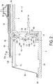
FIG. 2 is a vertical cross-sectional view illustrating the fiber-reinforced plastic producing device of a first embodiment of the present invention in a state in which the plate part of the movable stage is horizontal. -
FIG. 3 is a vertical cross-sectional view illustrating the fiber-reinforced plastic producing device of a first embodiment of the present invention in a state in which the plate part of the movable stage is inclined. -
FIG. 4 is a vertical cross-sectional view illustrating the fiber-reinforced plastic producing device of a first embodiment of the present invention in a state in which the movable stage is completely collapsed. -
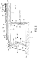
FIG. 5 is a vertical cross-sectional view illustrating the fiber-reinforced plastic producing device of a second embodiment of the present invention in a state in which the plate part of the movable stage is horizontal. -
FIG. 6 is a vertical cross-sectional view illustrating the fiber-reinforced plastic producing device of a second embodiment of the present invention in a state in which the plate part of the movable stage is inclined. -
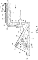
FIG. 7 is a vertical cross-sectional view illustrating the fiber-reinforced plastic producing device of a second embodiment of the present invention in a state in which the plate part of the movable stage is inclined and the end part is in contact with the base plate. -
FIG. 8 is a vertical cross-sectional view illustrating the fiber-reinforced plastic producing device of a second embodiment of the present invention in a state in which the movable stage is collapsed. - The fiber-reinforced plastic (FRP) producing device of a first embodiment of the present invention and a production method thereof will be described hereinafter with reference to the drawings.
- With the fiber-reinforced plastic producing method of this embodiment, after a
fabric 20 is shaped using a molding die 1 and amovable stage 11 constituting a fiber-reinforced plastic producing device such as that illustrated inFIG. 1 , a resin is injected into thefabric 20 so that a fiber-reinforced plastic molded product is formed. - The fiber-reinforced plastic is composed of the
fabric 20 and the resin. - The
fabric 20 is a laminate composed of a plurality of sheet-like members, and the required number of sheet-like members are laminated in accordance with the thickness of the molded product. Any fiber such as a carbon fiber or glass fiber may be used for thefabric 20. - The resin with which the
fabric 20 is impregnated is a thermosetting resin which cures by heating such as an epoxy resin, polyimide, polyurethane, or unsaturated polyester, for example. It is also possible to use a thermoplastic resin which hardens by heating such as a polyamide (for example, Nylon (trade name)), polyethylene, polystyrene, or polyvinyl chloride. - A convex-
shaped part 3 of the molding die 1 is mounted on thebase plate 2 so as to shape thefabric 20. The molding die 1 is then used directly for the molding of the fiber-reinforced plastic after the completion of the shaping of thefabric 20. The convex-shaped part 3 has afirst placement surface 3A on which thefabric 20 is placed and aformation surface 3B having a predetermined angle with respect to thefirst placement surface 3A. Since the convex-shapedpart 3 has thefirst placement surface 3A and theformation surface 3B, thefabric 20 is bent along thefirst placement surface 3A and theformation surface 3B so as to be formed into a cross-sectional shape corresponding to the convex-shapedpart 3. - Note that in the molding die 1, the
base plate 2 and the convex-shapedpart 3 may be separate units or may be formed integrally. - The
fabric 20 is disposed on thefirst placement surface 3A of the convex-shapedpart 3 of the molding die 1. Thefabric 20 is disposed while being aligned with the convex-shapedpart 3 so that a molded product having a desired shape is obtained in the shaping and subsequent molding steps. - In addition, molding members required to inject and mold the resin are disposed with respect to the
fabric 20. Here, molding members refer to members used in a resin transfer molding method such as, a fiber wovenfabric 31, aresin pass medium 41, apressure plate 32, aresin supply port 33, aninjection port 34, asuction port 35, and aback film 36. - The molding members that are used may be the same as the members used in an ordinary resin transfer molding method.
- The fiber woven
fabric 31 is disposed above thefabric 20 and below theresin pass medium 41 and is made of a fiber such as a polyamide (for example, Nylon (trade name)) or polyester, for example. The fiber wovenfabric 31 is disposed so that after the resin is cured, theresin supply port 33 does not adhere to the molded product so as to be formed integrally with the molded product. - The resin pass medium 41 is disposed above the fiber woven
fabric 31 so as to disperse the resin into the entire fabric. - The
pressure plate 32 is disposed between theback film 36 and thefabric 20 and above theresin pass medium 41. The surface of the fiber-reinforced plastic molded product facing theback film 36 is smoothened by thepressure plate 32. When the molded product is flat, a flat plate-like metal material is used for thepressure plate 32. When the cross-sectional shape of the molded product is an arc shape, for example, the cross section of thepressure plate 32 is formed into an arc shape. - The
resin supply port 33 is disposed above thepressure plate 32 as linear resin flow path along the longitudinal direction of the molding die 1. Theresin supply port 33 guides the resin from theinjection port 34 to the entireresin pass medium 41. - The
resin supply port 33 is a mesh-like member (thickness: approximately 0.15 to 4.0 mm), a spiral tube, a channel material, or the like made of a polypropylene or polyamide (for example, Nylon (trade name)). When theresin supply port 33 is a mesh-like member, the upper surface of theresin supply port 33 may be covered by theback film 36 so as to secure a resin flow path in a state in which it is compressed by theback film 36 due to vacuum suction. - The
injection port 34 from which the resin is injected is provided above thefirst placement surface 3A of the molding die 1, for example. - A
suction port 35 is provided in the formation surface of the molding die 1, and the space between theback film 36 and the molding die 1 is subjected to vacuum suction via thesuction port 35. Apermeable sheet 37, through which the resin cannot pass but which transmits air, and apermeable member 38 such as a fiber woven fabric are mounted on the inlet of thesuction port 35. - The
back film 36 is a high-elastic elongation film (such as Strechlon (trade name)), for example, and is disposed so as to cover the entirety of thefabric 20 or the mold 1 and themovable stage 11. -
FIG. 2 illustrates a state prior to vacuum suction.FIG. 3 illustrates a state during vacuum suction.FIG. 4 illustrates a state after vacuum suction.FIGS. 2 to 4 are vertical cross-sectional views taken along line a-a inFIG. 1 . - As illustrated in
FIG. 2 , the entirety of the molding die 1 and themovable stage 11, thefabric 20 and thepressure plate 32, and the like are covered from above by theback film 36, and the end part of theback film 36 is attached to thebase plate 2 of the molding die 1 using asealant 39. As a result, the space between theback film 36 and the molding die 1 is sealed. - Next, the
injection port 34 is closed, and the space between theback film 36 and the molding die 1 is subjected to vacuum suction from thesuction port 35 so that thefabric 20 is crimped against the convex-shapedpart 3 and thefabric 20 is shaped as illustrated inFIG. 4 . - In this embodiment, the sealed space further inside than the
back film 36 is decompressed to a vacuum pressure, and atmospheric pressure is applied to the outside of theback film 36 so that theback film 36 conforms to the molding die 1. As a result, thefabric 20 is shaped along the molding die 1 having the convex-shapedpart 3. - Note that the height of the convex-shaped
part 3 is set so that thefabric 20 that is shaped after vacuum suction does not reach thebase plate 2 of the molding die 1. - After shaping is complete, the
back film 36 adheres to thesealant 40 provided on theformation surface 3B, and theback film 36 is thereby attached snugly across the entire molding die 1. A thermosetting resin, for example, is then injected from theinjection port 34 so that thefabric 20 is impregnated with the resin. The space between theback film 36 and the molding die 1 is filled with the injected resin. Note that resin injection is achieved by a VaRTM method, an RTM method, an RFI method, or the like, and thefabric 20 is impregnated with the resin by these methods. - Next, the
movable stage 11 of this embodiment will be described. - The
movable stage 11 is provided with aplate part 13, aleg part 14 for supporting theplate part 13, a fixingpart 15 for fixing theleg part 14 to thebase plate 2, and the like. Themovable stage 11 is disposed adjacent to the molding die 1. - The
plate part 13 is a plate-like member, and the upper surface of theplate part 13 is asecond placement surface 13A on which theend part 20a side of thefabric 20 is placed. Thesecond placement surface 13A is disposed at a position contiguous with the adjacentfirst placement surface 3A. That is, in a state before thefabric 20 is pressed using theback film 36, the end part of thesecond placement surface 13A of theplate part 13 on the side near the molding die 1 and thefirst connection part 16 described below is at roughly the same height as the end part of thefirst placement surface 3A. For example, when thesecond placement surface 13A of theplate part 13 is in a horizontal state, thesecond placement surface 13A is an extension of thefirst placement surface 3A of the molding die 1, as illustrated inFIG. 2 . Note that when applied to a molded product with an arc-shaped cross section or the like, theplate part 13 may not be disposed in a horizontal state at the stage prior to pressure by theback film 36. Also, note that a gap of approximately 5 mm may be provided between thefirst placement surface 3A and thesecond placement surface 13A and that the position at which thefirst placement surface 3A and thesecond placement surface 13A described above continue from one another includes cases in which a gap is provided between the two units in this way. - A
first connection part 16 connected to the upper end of theleg part 14 is provided on one end side of theplate part 13, and aguide member 19 with a curved outer circumferential surface is provided on the other end side of theplate part 13. Theleg part 14 which supports theplate part 13 is connected to theplate part 13 on the molding die 1 side of theplate part 13. - Prior to vacuum suction, the
first connection part 16 supports theplate part 13 horizontally. When theback film 36 presses against theplate part 13 due to vacuum suction and a load of at least a prescribed amount is applied from above theplate part 13, theplate part 13 is rotated using the axis of thefirst connection part 16 as a fulcrum. Theplate part 13 rotates around the axis of thefirst connection part 16. - When the other end side of the
plate part 13 touches thebase plate 2, theguide member 19 moves theplate part 13 smoothly over thebase plate 2 while smoothly rotating theplate part 13. As illustrated inFIG. 4 , agroove 2A corresponding to theguide member 19 is formed on thebase plate 2 so that theplate part 13 is horizontal when themovable stage 11 is completely collapsed. In addition, a sidewall surface is formed in thegroove 2A on themovable stage 11 side, and this sidewall surface interlocks with theguide member 19 so that themovable stage 11 switches the operation from the rotation of theplate part 13 to the bending of theleg part 14. - An elastic member such as a
compression spring 16A, for example, is provided on thefirst connection part 16 so as to support theplate part 13 horizontally until a predetermined load is applied. - The
leg part 14 contracts in the height direction of the molding die 1 and can move theplate part 13 below thefirst placement surface 3A of the molding die 1. The upper end side of theleg part 14 is connected to theplate part 13, and the lower end side thereof is connected to the fixingpart 15. - The
leg part 14 is provided with two rod-like members second connection part 17 to which the two rod-like members like members second connection part 17 maintains the height of theleg part 14. When theback film 36 presses against theplate part 13 due to vacuum suction and a load of at least a prescribed amount is applied to theplate part 13 from above, the two rod-like members second connection part 17 as a fulcrum. The two rod-like members second connection part 17. - The fixing
part 15 is linked to thebase plate 2 by a bolt or the like, for example, so as to fix themovable stage 11 to the top of thebase plate 2. - A
third connection part 18 connected to the lower end of theleg part 14 is provided on one end side of the fixingpart 15. In thethird connection part 18 to which the fixingpart 15 and the rod-like member 14B of theleg part 14 are connected, the rod-like member 14B of theleg part 14 rotates. Until a predetermined load is applied, thethird connection part 18 maintains the height of theleg part 14. When theback film 36 presses against theplate part 13 due to vacuum suction and a load of at least a prescribed amount is applied to theplate part 13 from above, the rod-like member 14B is rotated with respect to fixingpart 15 using the axis of thethird connection part 18 as a fulcrum. The rod-like member 14B rotates around the axis of thethird connection part 18. - In the
second connection part 17 and thethird connection part 18, the rod-like members leg part 14 contracts in the height direction of the molding die 1. At this time, the position in the height direction of thefirst connection part 16 moves to a lower position from roughly the same height as thefirst placement surface 3A. - Elastic members such as compression springs 17A and 18A, for example, are respectively provided on the
second connection part 17 and thethird connection part 18 so as to maintain the height of theleg part 14 until a predetermined load is applied. - The elastic forces of the compression springs 17A and 18A of the
second connection part 17 and thethird connection part 18 are roughly equal, and the elastic force of thecompression spring 16A of thefirst connection part 16 is lower than the elastic forces of the compression springs 17A and 18A. As a result, when the sealed space further inside than theback film 36 is decompressed to a vacuum pressure and a predetermined load is applied to theplate part 13, theplate part 13 is first rotated and inclined with respect to theleg part 14 as illustrated inFIG. 3 while the height of theleg part 14 is maintained. When vacuum suction is then continued, theplate part 13 is pressed downward by theback film 36 so that theleg part 14 bends. - When the
leg part 14 bends completely, a state such as that illustrated inFIG. 4 is achieved. At this time, theleg part 14 remains compressed further inside than theback film 36. Thefabric 20 is then impregnated with a resin in this state, and thefabric 20 impregnated with the resin is heated. Accordingly, theleg part 14 has a quality capable of withstanding the temperature when the resin is heated (for example, approximately 140°C. - As described above, with this embodiment, since the molding die 1 has a
first placement surface 3A and aformation surface 3B, thefabric 20 is bent along thefirst placement surface 3A and theformation surface 3B so as to be formed into a cross-sectional shape corresponding to the molding die. - In addition, the state transitions from a state in which the
first placement surface 3A of the molding die 1 and thesecond placement surface 13A of themovable stage 11 are of roughly the same height and thefabric 20 is placed on thefirst placement surface 3A and thesecond placement surface 13A, as illustrated inFIG. 2 , to a state in which thesecond placement surface 13A of themovable stage 11 is inclined with respect to thefirst placement surface 3A, as illustrated inFIG. 3 . Thesecond placement surface 13A of themovable stage 11 is inclined with respect to thefirst placement surface 3A in a state in which the molding die 1 side is higher than the opposite side of the molding die 1 side. As a result, thefabric 20 is bent at the boundary between thefirst placement surface 3A and thesecond placement surface 13A along the edge of thefirst placement surface 3A of the molding die 1. - The
second placement surface 13A then moves below thefirst placement surface 3A so that thefabric 20 is disposed along theformation surface 3B of the molding die 1. When thesecond placement surface 13A moves below thefirst placement surface 3A, thesecond placement surface 13A of themovable stage 11 is inclined with respect to thefirst placement surface 3A, and thefabric 20 is supported from below, Therefore, wrinkles and folds are less likely to be formed in the bent portion of thefabric 20 than when amovable stage 11 is not used. - In addition, as described above, when the
fabric 20 is pressed using theback film 36, a pressing force is applied to thefabric 20 in the order of the location corresponding to the edge of thefirst placement surface 3A having the shape of the convex-shapedpart 3 to the end of thefabric 20. As a result, sliding between each layer of thefabric 20 is possible, and the generation of wrinkles after shaping can be suppressed. - The fiber-reinforced plastic (FRP) producing device of a second embodiment of the present invention and a production method thereof will be described hereinafter with reference to
FIGS. 5 to 8 . - In the embodiment described above, a configuration in which the
leg part 14 is fixed to the molding die 1 side and the end part on the opposite side of the molding die 1 side of theplate part 13 moves downward was described, but the position of theleg part 14 in the second embodiment differs from that of the first embodiment. - That is, in the second embodiment, as in the first embodiment, a
movable stage 12 is disposed adjacent to the molding die 1. When thesecond placement surface 13A of theplate part 13 is in a horizontal state, thesecond placement surface 13A is an extension of thefirst placement surface 3A of the molding die and forms a continuous plane. Note that when applied to a molded product with an arc-shaped cross section or the like, theplate part 13 may not be disposed in a horizontal state at the stage prior to pressure by theback film 36. Also note that, as in the first embodiment, a gap of approximately 5 mm may be provided between thefirst placement surface 3A and thesecond placement surface 13A and that the position at which thefirst placement surface 3A and thesecond placement surface 13A described above continue from one another includes cases in which a gap is provided between the two units in this way. - The
leg part 14 which supports theplate part 13 is then connected to theplate part 13 on the opposite side of the molding die 1 side of theplate part 13. The end part on the molding die 1 side of theplate part 13 then moves downward. - In this embodiment, when the sealed space further inside than the
back film 36 is decompressed to a vacuum pressure and a predetermined load is applied to theplate part 13, theplate part 13 is first rotated with respect to theleg part 14 as illustrated inFIG. 6 while the height of theleg part 14 is maintained. When vacuum suction is then continued, theplate part 13 is pressed downward by theback film 36 so that theleg part 14 bends, as illustrated inFIG. 7 . When theleg part 14 bends completely, a state such as that illustrated inFIG. 8 is achieved. - The
second placement surface 13A of themovable stage 12 is inclined with respect to thefirst placement surface 3A in a state in which the opposite side of the molding die 1 side is higher than the molding die 1 side. As a result, as illustrated inFIG. 6 , thefabric 20 is bent at the edge of thefirst placement surface 3A and is bent near a point in contact with thesecond placement surface 13A. That is, when thesecond placement surface 13A of themovable stage 12 is inclined with respect to thefirst placement surface 3A, thefabric 20 is bent twice, and the respective bending directions are opposite one another, so misalignment is unlikely to occur between the inside layer and the outside layer of thefabric 20. In addition, since thesecond placement surface 13A of themovable stage 12 supports thefabric 20 from below, wrinkles are less likely to be formed in the bent portion of thefabric 20 than when amovable stage 11 is not used. - Note that in the embodiments described above, a case having a configuration in which the
leg part 14 bends like a joint was described as the contraction mechanism in the height direction of theleg part 14 of themovable stage 11, but the present invention is not limited to this example. For example, the contraction mechanism in the height direction of the leg part may have a telescopic configuration which expands and contracts in response to one member moving in and out of another member. -
- 1
- Molding die
- 2
- Base plate
- 2A
- Groove
- 3
- Convex-shaped part
- 3A
- First placement surface
- 3B
- Formation surface
- 11, 12
- Movable stage
- 13
- Plate part
- 13A
- Second placement surface
- 14
- Leg part
- 15
- Fixed part
- 16
- First connection part
- 17
- Second connection part
- 18
- Third connection part
- 16A, 17A, 18A
- Compression spring
- 19
- Guide member
- 20
- Fabric
- 31
- Fiber woven fabric
- 32
- Pressure plate
- 33
- Resin supply port
- 34
- Injection port
- 35
- Suction port
- 36
- Back film
- 37
- Permeable sheet
- 38
- Permeable member
- 39, 40
- Sealant
- 41
- Resin pass medium
Claims (9)
- A fiber-reinforced plastic producing device comprising:a molding die having a first placement surface for the placement of a fabric and a formation surface having a predetermined angle with respect to the first placement surface; anda movable stage having a second placement surface for the placement of an end side of the fabric, and being disposed adjacent to the molding die;the movable stage being configured so that the second placement surface forms a continuous plane with the first placement surface and can move below the first placement surface after being inclined with respect to the first placement surface.
- The fiber-reinforced plastic producing device according to claim 1, wherein the second placement surface of the movable stage is configured so as to be inclined with respect to the first placement surface in a state in which the molding die side is higher than the opposite side of the molding die side.
- The fiber-reinforced plastic producing device according to claim 1, wherein the second placement surface of the movable stage is configured so as to be inclined with respect to the first placement surface in a state in which the opposite side of the molding die side is higher than the molding die side.
- The fiber-reinforced plastic producing device according to any one of claims 1 to 3, wherein the movable stage further include a leg part which supports the second placement surface and contracts in a height direction of the molding die; and a connection part with which the second placement surface and the leg part are connected so that the second placement surface rotates with respect to the leg part.
- The fiber-reinforced plastic producing device according to claim 4, wherein a first elastic member is provided in the connection part; a second elastic member is provided in the leg part; and an elastic force of the first elastic member is lower than an elastic force of the second elastic member.
- A movable stage having a second placement surface disposed adjacent to a molding die having a formation surface having a predetermined angle with respect to a first placement surface, an end side of a fabric being placed on the second placement surface when the fabric is placed on the first placement surface; and the second placement surface being configured so that the second placement surface forms a continuous plane with the first placement surface and can move below the first placement surface after being inclined with respect to the first placement surface.
- A shaped fabric producing method comprising:placing a fabric on a first placement surface in a molding die having a first placement surface and a formation surface having a predetermined angle with respect to the first placement surface;placing an end side of the fabric on a second placement surface set so as to form a continuous surface with the first placement surface in a movable stage having a second placement surface and being disposed adjacent to the molding die;allowing the second placement surface to be inclined with respect to the first placement surface; andmoving the second placement surface to below the first placement surface.
- The shaped fabric producing method according to claim 7 further comprising:covering the fabric placed on the first placement surface and the second placement surface with a back film; andperforming vacuum suction on a space further inside than the back film;wherein the space further inside than the back film is depressurized, and the back film presses against the second placement surface so that the second placement surface is inclined with respect to the first placement surface and moves below the first placement surface.
- A fiber-reinforced plastic producing method comprising:placing a fabric on a first placement surface of a molding die having a first placement surface and a formation surface having a predetermined angle with respect to the first placement surface;placing an end side of the fabric on a second placement surface set so as to form a continuous surface with the first placement surface in a movable stage having a second placement surface and being disposed adjacent to the molding die;allowing the second placement surface to be inclined with respect to the first placement surface;moving the second placement surface to below the first placement surface;covering the fabric placed on the first placement surface and the second placement surface with a back film;performing vacuum suction on a space further inside than the back film; andinjecting a resin into the space further inside than the back film.
Applications Claiming Priority (2)
| Application Number | Priority Date | Filing Date | Title |
|---|---|---|---|
| JP2015155896A JP6537921B2 (en) | 2015-08-06 | 2015-08-06 | Apparatus for producing fiber-reinforced plastic, movable base, method for producing shaped fiber substrate, and method for producing fiber-reinforced plastic |
| PCT/JP2016/072346 WO2017022667A1 (en) | 2015-08-06 | 2016-07-29 | Fiber-reinforced-plastic producing device, movable stage, shaped fiber base material producing method, and fiber-reinforced-plastic producing method |
Publications (3)
| Publication Number | Publication Date |
|---|---|
| EP3287248A1 true EP3287248A1 (en) | 2018-02-28 |
| EP3287248A4 EP3287248A4 (en) | 2018-06-13 |
| EP3287248B1 EP3287248B1 (en) | 2020-07-08 |
Family
ID=57943944
Family Applications (1)
| Application Number | Title | Priority Date | Filing Date |
|---|---|---|---|
| EP16832946.4A Active EP3287248B1 (en) | 2015-08-06 | 2016-07-29 | Fiber-reinforced-plastic producing device, movable stage, shaped fiber base material producing method, and fiber-reinforced-plastic producing method |
Country Status (5)
| Country | Link |
|---|---|
| US (1) | US10807282B2 (en) |
| EP (1) | EP3287248B1 (en) |
| JP (1) | JP6537921B2 (en) |
| CA (1) | CA2985987C (en) |
| WO (1) | WO2017022667A1 (en) |
Cited By (1)
| Publication number | Priority date | Publication date | Assignee | Title |
|---|---|---|---|---|
| EP3505320A1 (en) * | 2017-12-29 | 2019-07-03 | Premium AEROTEC GmbH | Method and device for producing a fibre preform |
Families Citing this family (14)
| Publication number | Priority date | Publication date | Assignee | Title |
|---|---|---|---|---|
| US10688697B2 (en) * | 2016-01-22 | 2020-06-23 | The Boeing Company | Apparatus and method of forming a composite structure |
| JP6543577B2 (en) | 2016-01-22 | 2019-07-10 | 三菱重工業株式会社 | Method of forming composite material and jig for forming composite material |
| US10213968B2 (en) * | 2016-03-04 | 2019-02-26 | The Boeing Company | Dynamic forming tools for composite parts |
| JP6804211B2 (en) * | 2016-03-31 | 2020-12-23 | 三菱航空機株式会社 | Molding method of reinforcing fiber base material |
| JP6717105B2 (en) * | 2016-08-08 | 2020-07-01 | 三菱ケミカル株式会社 | Method for producing fiber-reinforced resin molding |
| US10987880B2 (en) | 2016-09-07 | 2021-04-27 | Mitsubishi Heavy Industries, Ltd. | Method for molding composite material and jig for molding composite material |
| JP7162346B2 (en) * | 2019-11-22 | 2022-10-28 | 株式会社micro-AMS | Electromagnetic wave forming device and electromagnetic wave forming method |
| US11260607B2 (en) * | 2020-02-11 | 2022-03-01 | The Boeing Company | Forming systems and methods for drape forming a composite charge |
| US11498288B2 (en) * | 2020-02-11 | 2022-11-15 | The Boeing Company | Forming systems and methods for drape forming a composite charge |
| JP7310027B2 (en) * | 2020-07-31 | 2023-07-18 | 三菱重工業株式会社 | Shaping device and method |
| US12138868B2 (en) | 2021-01-04 | 2024-11-12 | The Boeing Company | Drape forming apparatus and device, and method of forming a composite structure |
| JP7679027B2 (en) * | 2021-06-07 | 2025-05-19 | トヨタ紡織株式会社 | Method for manufacturing fiber-resin molded body |
| JP2024162802A (en) * | 2023-05-11 | 2024-11-21 | 三菱重工業株式会社 | Shaping device and shaping method |
| JP2025012453A (en) * | 2023-07-13 | 2025-01-24 | 三菱重工業株式会社 | Molded product manufacturing method and molded product manufacturing device |
Family Cites Families (12)
| Publication number | Priority date | Publication date | Assignee | Title |
|---|---|---|---|---|
| US5648109A (en) * | 1995-05-03 | 1997-07-15 | Massachusetts Institute Of Technology | Apparatus for diaphragm forming |
| JP3117118B2 (en) * | 1995-07-31 | 2000-12-11 | ヒーハイスト精工株式会社 | Multi-degree-of-freedom positioning mechanism |
| US20030075657A1 (en) * | 2001-10-18 | 2003-04-24 | Pierre Joubert | Scissors lift with combination wedge and lever mechanism |
| JP2006312260A (en) * | 2005-05-09 | 2006-11-16 | Fuji Heavy Ind Ltd | Pre-preg bending apparatus and bending method thereof |
| JP4967405B2 (en) | 2006-03-27 | 2012-07-04 | 東レ株式会社 | Manufacturing method of fiber reinforced plastic |
| ES2443917T3 (en) * | 2007-10-09 | 2014-02-21 | Saab Ab | Procedure and device for forming a composite material |
| EP2116358B1 (en) * | 2008-05-09 | 2016-06-29 | Saab Ab | Method and apparatus for conforming a blank |
| JP5226470B2 (en) * | 2008-11-13 | 2013-07-03 | 富士重工業株式会社 | Bending machine |
| JP2010120167A (en) * | 2008-11-17 | 2010-06-03 | Toray Ind Inc | Method of manufacturing preform and fiber reinforced plastic |
| JP5533743B2 (en) * | 2010-09-24 | 2014-06-25 | 東レ株式会社 | Manufacturing method of fiber reinforced plastic |
| US9914268B2 (en) * | 2014-06-04 | 2018-03-13 | The Boeing Company | Systems and methods for defining a surface contour of a layered charge of material |
| US10479029B2 (en) * | 2015-01-16 | 2019-11-19 | The Boeing Company | Composite forming apparatus |
-
2015
- 2015-08-06 JP JP2015155896A patent/JP6537921B2/en active Active
-
2016
- 2016-07-29 WO PCT/JP2016/072346 patent/WO2017022667A1/en not_active Ceased
- 2016-07-29 EP EP16832946.4A patent/EP3287248B1/en active Active
- 2016-07-29 US US15/572,363 patent/US10807282B2/en active Active
- 2016-07-29 CA CA2985987A patent/CA2985987C/en active Active
Cited By (1)
| Publication number | Priority date | Publication date | Assignee | Title |
|---|---|---|---|---|
| EP3505320A1 (en) * | 2017-12-29 | 2019-07-03 | Premium AEROTEC GmbH | Method and device for producing a fibre preform |
Also Published As
| Publication number | Publication date |
|---|---|
| CA2985987C (en) | 2019-12-17 |
| EP3287248B1 (en) | 2020-07-08 |
| JP2017030329A (en) | 2017-02-09 |
| WO2017022667A1 (en) | 2017-02-09 |
| EP3287248A4 (en) | 2018-06-13 |
| JP6537921B2 (en) | 2019-07-03 |
| CA2985987A1 (en) | 2017-02-09 |
| US10807282B2 (en) | 2020-10-20 |
| US20180126604A1 (en) | 2018-05-10 |
Similar Documents
| Publication | Publication Date | Title |
|---|---|---|
| US10807282B2 (en) | Fiber-reinforced plastic producing device, movable stage, shaped fabric producing method, and fiber-reinforced plastic producing method | |
| EP2116358B1 (en) | Method and apparatus for conforming a blank | |
| US11826969B2 (en) | Diaphragm forming | |
| CN106414031B (en) | Apparatus and method for forming a flange | |
| US11701797B2 (en) | Composite material molding jig and composite material molding method | |
| EP4035878B1 (en) | Preform shaping apparatus and preform shaping method | |
| JP6239272B2 (en) | Method and apparatus for molding fiber reinforced plastic member | |
| US20190210320A1 (en) | Fiber-composite sandwich material containing shape-memory alloys | |
| EP2954994B1 (en) | Systems and methods for defining a surface contour of a layered charge of material | |
| JP6281865B2 (en) | FRP forming jig and FRP structure forming method | |
| US12172396B2 (en) | Systems and methods for manufacturing large contoured parts from thermoplastic laminate sheets | |
| JP2014015041A (en) | Apparatus for manufacturing flanged composite component and method of manufacturing said flanged composite component | |
| JP2006335049A (en) | Composite sheet processing apparatus and composite structure forming method | |
| JP6197105B2 (en) | System for forming a stack of composite materials | |
| EP2295228B1 (en) | Method of manufacturing a fuselage frame of composite material | |
| JP2018122523A (en) | Bagging sheet | |
| US10144170B2 (en) | Device and method for shaping a semi-finished fiber product | |
| US12128639B2 (en) | Forming device and forming method | |
| EP3785891B1 (en) | Preform shaping method and composite material molding method | |
| EP4472832B1 (en) | Concavity diaphragm forming | |
| US12496786B2 (en) | Forming method |
Legal Events
| Date | Code | Title | Description |
|---|---|---|---|
| STAA | Information on the status of an ep patent application or granted ep patent |
Free format text: STATUS: THE INTERNATIONAL PUBLICATION HAS BEEN MADE |
|
| PUAI | Public reference made under article 153(3) epc to a published international application that has entered the european phase |
Free format text: ORIGINAL CODE: 0009012 |
|
| STAA | Information on the status of an ep patent application or granted ep patent |
Free format text: STATUS: REQUEST FOR EXAMINATION WAS MADE |
|
| 17P | Request for examination filed |
Effective date: 20171120 |
|
| AK | Designated contracting states |
Kind code of ref document: A1 Designated state(s): AL AT BE BG CH CY CZ DE DK EE ES FI FR GB GR HR HU IE IS IT LI LT LU LV MC MK MT NL NO PL PT RO RS SE SI SK SM TR |
|
| AX | Request for extension of the european patent |
Extension state: BA ME |
|
| REG | Reference to a national code |
Ref country code: DE Ref legal event code: R079 Ref document number: 602016039710 Country of ref document: DE Free format text: PREVIOUS MAIN CLASS: B29C0039100000 Ipc: B29C0053020000 |
|
| A4 | Supplementary search report drawn up and despatched |
Effective date: 20180516 |
|
| RIC1 | Information provided on ipc code assigned before grant |
Ipc: B29C 70/44 20060101ALI20180509BHEP Ipc: B29C 53/02 20060101AFI20180509BHEP |
|
| DAV | Request for validation of the european patent (deleted) | ||
| DAX | Request for extension of the european patent (deleted) | ||
| STAA | Information on the status of an ep patent application or granted ep patent |
Free format text: STATUS: EXAMINATION IS IN PROGRESS |
|
| 17Q | First examination report despatched |
Effective date: 20190402 |
|
| GRAP | Despatch of communication of intention to grant a patent |
Free format text: ORIGINAL CODE: EPIDOSNIGR1 |
|
| STAA | Information on the status of an ep patent application or granted ep patent |
Free format text: STATUS: GRANT OF PATENT IS INTENDED |
|
| INTG | Intention to grant announced |
Effective date: 20200213 |
|
| GRAS | Grant fee paid |
Free format text: ORIGINAL CODE: EPIDOSNIGR3 |
|
| GRAA | (expected) grant |
Free format text: ORIGINAL CODE: 0009210 |
|
| STAA | Information on the status of an ep patent application or granted ep patent |
Free format text: STATUS: THE PATENT HAS BEEN GRANTED |
|
| AK | Designated contracting states |
Kind code of ref document: B1 Designated state(s): AL AT BE BG CH CY CZ DE DK EE ES FI FR GB GR HR HU IE IS IT LI LT LU LV MC MK MT NL NO PL PT RO RS SE SI SK SM TR |
|
| REG | Reference to a national code |
Ref country code: CH Ref legal event code: EP Ref country code: AT Ref legal event code: REF Ref document number: 1287982 Country of ref document: AT Kind code of ref document: T Effective date: 20200715 |
|
| REG | Reference to a national code |
Ref country code: DE Ref legal event code: R096 Ref document number: 602016039710 Country of ref document: DE |
|
| REG | Reference to a national code |
Ref country code: IE Ref legal event code: FG4D |
|
| REG | Reference to a national code |
Ref country code: LT Ref legal event code: MG4D |
|
| REG | Reference to a national code |
Ref country code: AT Ref legal event code: MK05 Ref document number: 1287982 Country of ref document: AT Kind code of ref document: T Effective date: 20200708 |
|
| REG | Reference to a national code |
Ref country code: NL Ref legal event code: MP Effective date: 20200708 |
|
| PG25 | Lapsed in a contracting state [announced via postgrant information from national office to epo] |
Ref country code: ES Free format text: LAPSE BECAUSE OF FAILURE TO SUBMIT A TRANSLATION OF THE DESCRIPTION OR TO PAY THE FEE WITHIN THE PRESCRIBED TIME-LIMIT Effective date: 20200708 Ref country code: GR Free format text: LAPSE BECAUSE OF FAILURE TO SUBMIT A TRANSLATION OF THE DESCRIPTION OR TO PAY THE FEE WITHIN THE PRESCRIBED TIME-LIMIT Effective date: 20201009 Ref country code: BG Free format text: LAPSE BECAUSE OF FAILURE TO SUBMIT A TRANSLATION OF THE DESCRIPTION OR TO PAY THE FEE WITHIN THE PRESCRIBED TIME-LIMIT Effective date: 20201008 Ref country code: SE Free format text: LAPSE BECAUSE OF FAILURE TO SUBMIT A TRANSLATION OF THE DESCRIPTION OR TO PAY THE FEE WITHIN THE PRESCRIBED TIME-LIMIT Effective date: 20200708 Ref country code: PT Free format text: LAPSE BECAUSE OF FAILURE TO SUBMIT A TRANSLATION OF THE DESCRIPTION OR TO PAY THE FEE WITHIN THE PRESCRIBED TIME-LIMIT Effective date: 20201109 Ref country code: HR Free format text: LAPSE BECAUSE OF FAILURE TO SUBMIT A TRANSLATION OF THE DESCRIPTION OR TO PAY THE FEE WITHIN THE PRESCRIBED TIME-LIMIT Effective date: 20200708 Ref country code: LT Free format text: LAPSE BECAUSE OF FAILURE TO SUBMIT A TRANSLATION OF THE DESCRIPTION OR TO PAY THE FEE WITHIN THE PRESCRIBED TIME-LIMIT Effective date: 20200708 Ref country code: FI Free format text: LAPSE BECAUSE OF FAILURE TO SUBMIT A TRANSLATION OF THE DESCRIPTION OR TO PAY THE FEE WITHIN THE PRESCRIBED TIME-LIMIT Effective date: 20200708 Ref country code: AT Free format text: LAPSE BECAUSE OF FAILURE TO SUBMIT A TRANSLATION OF THE DESCRIPTION OR TO PAY THE FEE WITHIN THE PRESCRIBED TIME-LIMIT Effective date: 20200708 Ref country code: NO Free format text: LAPSE BECAUSE OF FAILURE TO SUBMIT A TRANSLATION OF THE DESCRIPTION OR TO PAY THE FEE WITHIN THE PRESCRIBED TIME-LIMIT Effective date: 20201008 |
|
| PG25 | Lapsed in a contracting state [announced via postgrant information from national office to epo] |
Ref country code: RS Free format text: LAPSE BECAUSE OF FAILURE TO SUBMIT A TRANSLATION OF THE DESCRIPTION OR TO PAY THE FEE WITHIN THE PRESCRIBED TIME-LIMIT Effective date: 20200708 Ref country code: LV Free format text: LAPSE BECAUSE OF FAILURE TO SUBMIT A TRANSLATION OF THE DESCRIPTION OR TO PAY THE FEE WITHIN THE PRESCRIBED TIME-LIMIT Effective date: 20200708 Ref country code: PL Free format text: LAPSE BECAUSE OF FAILURE TO SUBMIT A TRANSLATION OF THE DESCRIPTION OR TO PAY THE FEE WITHIN THE PRESCRIBED TIME-LIMIT Effective date: 20200708 Ref country code: IS Free format text: LAPSE BECAUSE OF FAILURE TO SUBMIT A TRANSLATION OF THE DESCRIPTION OR TO PAY THE FEE WITHIN THE PRESCRIBED TIME-LIMIT Effective date: 20201108 |
|
| REG | Reference to a national code |
Ref country code: CH Ref legal event code: PL |
|
| PG25 | Lapsed in a contracting state [announced via postgrant information from national office to epo] |
Ref country code: NL Free format text: LAPSE BECAUSE OF FAILURE TO SUBMIT A TRANSLATION OF THE DESCRIPTION OR TO PAY THE FEE WITHIN THE PRESCRIBED TIME-LIMIT Effective date: 20200708 |
|
| REG | Reference to a national code |
Ref country code: DE Ref legal event code: R097 Ref document number: 602016039710 Country of ref document: DE |
|
| REG | Reference to a national code |
Ref country code: BE Ref legal event code: MM Effective date: 20200731 |
|
| PG25 | Lapsed in a contracting state [announced via postgrant information from national office to epo] |
Ref country code: EE Free format text: LAPSE BECAUSE OF FAILURE TO SUBMIT A TRANSLATION OF THE DESCRIPTION OR TO PAY THE FEE WITHIN THE PRESCRIBED TIME-LIMIT Effective date: 20200708 Ref country code: IT Free format text: LAPSE BECAUSE OF FAILURE TO SUBMIT A TRANSLATION OF THE DESCRIPTION OR TO PAY THE FEE WITHIN THE PRESCRIBED TIME-LIMIT Effective date: 20200708 Ref country code: SM Free format text: LAPSE BECAUSE OF FAILURE TO SUBMIT A TRANSLATION OF THE DESCRIPTION OR TO PAY THE FEE WITHIN THE PRESCRIBED TIME-LIMIT Effective date: 20200708 Ref country code: LU Free format text: LAPSE BECAUSE OF NON-PAYMENT OF DUE FEES Effective date: 20200729 Ref country code: LI Free format text: LAPSE BECAUSE OF NON-PAYMENT OF DUE FEES Effective date: 20200731 Ref country code: RO Free format text: LAPSE BECAUSE OF FAILURE TO SUBMIT A TRANSLATION OF THE DESCRIPTION OR TO PAY THE FEE WITHIN THE PRESCRIBED TIME-LIMIT Effective date: 20200708 Ref country code: CH Free format text: LAPSE BECAUSE OF NON-PAYMENT OF DUE FEES Effective date: 20200731 Ref country code: DK Free format text: LAPSE BECAUSE OF FAILURE TO SUBMIT A TRANSLATION OF THE DESCRIPTION OR TO PAY THE FEE WITHIN THE PRESCRIBED TIME-LIMIT Effective date: 20200708 Ref country code: CZ Free format text: LAPSE BECAUSE OF FAILURE TO SUBMIT A TRANSLATION OF THE DESCRIPTION OR TO PAY THE FEE WITHIN THE PRESCRIBED TIME-LIMIT Effective date: 20200708 |
|
| PLBE | No opposition filed within time limit |
Free format text: ORIGINAL CODE: 0009261 |
|
| STAA | Information on the status of an ep patent application or granted ep patent |
Free format text: STATUS: NO OPPOSITION FILED WITHIN TIME LIMIT |
|
| PG25 | Lapsed in a contracting state [announced via postgrant information from national office to epo] |
Ref country code: BE Free format text: LAPSE BECAUSE OF NON-PAYMENT OF DUE FEES Effective date: 20200731 Ref country code: AL Free format text: LAPSE BECAUSE OF FAILURE TO SUBMIT A TRANSLATION OF THE DESCRIPTION OR TO PAY THE FEE WITHIN THE PRESCRIBED TIME-LIMIT Effective date: 20200708 |
|
| 26N | No opposition filed |
Effective date: 20210409 |
|
| GBPC | Gb: european patent ceased through non-payment of renewal fee |
Effective date: 20201008 |
|
| PG25 | Lapsed in a contracting state [announced via postgrant information from national office to epo] |
Ref country code: SK Free format text: LAPSE BECAUSE OF FAILURE TO SUBMIT A TRANSLATION OF THE DESCRIPTION OR TO PAY THE FEE WITHIN THE PRESCRIBED TIME-LIMIT Effective date: 20200708 |
|
| PG25 | Lapsed in a contracting state [announced via postgrant information from national office to epo] |
Ref country code: GB Free format text: LAPSE BECAUSE OF NON-PAYMENT OF DUE FEES Effective date: 20201008 Ref country code: IE Free format text: LAPSE BECAUSE OF NON-PAYMENT OF DUE FEES Effective date: 20200729 Ref country code: SI Free format text: LAPSE BECAUSE OF FAILURE TO SUBMIT A TRANSLATION OF THE DESCRIPTION OR TO PAY THE FEE WITHIN THE PRESCRIBED TIME-LIMIT Effective date: 20200708 |
|
| PG25 | Lapsed in a contracting state [announced via postgrant information from national office to epo] |
Ref country code: TR Free format text: LAPSE BECAUSE OF FAILURE TO SUBMIT A TRANSLATION OF THE DESCRIPTION OR TO PAY THE FEE WITHIN THE PRESCRIBED TIME-LIMIT Effective date: 20200708 Ref country code: MT Free format text: LAPSE BECAUSE OF FAILURE TO SUBMIT A TRANSLATION OF THE DESCRIPTION OR TO PAY THE FEE WITHIN THE PRESCRIBED TIME-LIMIT Effective date: 20200708 Ref country code: CY Free format text: LAPSE BECAUSE OF FAILURE TO SUBMIT A TRANSLATION OF THE DESCRIPTION OR TO PAY THE FEE WITHIN THE PRESCRIBED TIME-LIMIT Effective date: 20200708 |
|
| PG25 | Lapsed in a contracting state [announced via postgrant information from national office to epo] |
Ref country code: MK Free format text: LAPSE BECAUSE OF FAILURE TO SUBMIT A TRANSLATION OF THE DESCRIPTION OR TO PAY THE FEE WITHIN THE PRESCRIBED TIME-LIMIT Effective date: 20200708 Ref country code: MC Free format text: LAPSE BECAUSE OF FAILURE TO SUBMIT A TRANSLATION OF THE DESCRIPTION OR TO PAY THE FEE WITHIN THE PRESCRIBED TIME-LIMIT Effective date: 20200708 |
|
| PGFP | Annual fee paid to national office [announced via postgrant information from national office to epo] |
Ref country code: FR Payment date: 20250610 Year of fee payment: 10 |
|
| PGFP | Annual fee paid to national office [announced via postgrant information from national office to epo] |
Ref country code: DE Payment date: 20250604 Year of fee payment: 10 |