EP3287064A1 - Endoscope system - Google Patents
Endoscope system Download PDFInfo
- Publication number
- EP3287064A1 EP3287064A1 EP16782860.7A EP16782860A EP3287064A1 EP 3287064 A1 EP3287064 A1 EP 3287064A1 EP 16782860 A EP16782860 A EP 16782860A EP 3287064 A1 EP3287064 A1 EP 3287064A1
- Authority
- EP
- European Patent Office
- Prior art keywords
- optical
- optical fiber
- connector
- signal
- fiber
- Prior art date
- Legal status (The legal status is an assumption and is not a legal conclusion. Google has not performed a legal analysis and makes no representation as to the accuracy of the status listed.)
- Withdrawn
Links
- 230000003287 optical effect Effects 0.000 claims abstract description 150
- 239000013307 optical fiber Substances 0.000 claims abstract description 78
- 230000005540 biological transmission Effects 0.000 claims abstract description 14
- 238000003384 imaging method Methods 0.000 claims abstract description 6
- 238000012937 correction Methods 0.000 claims description 24
- 239000000835 fiber Substances 0.000 claims description 10
- 238000004891 communication Methods 0.000 claims description 8
- 230000000087 stabilizing effect Effects 0.000 claims description 6
- 238000003780 insertion Methods 0.000 description 15
- 230000037431 insertion Effects 0.000 description 15
- 230000010365 information processing Effects 0.000 description 14
- 238000005286 illumination Methods 0.000 description 10
- 238000005452 bending Methods 0.000 description 8
- 238000010586 diagram Methods 0.000 description 8
- 238000012545 processing Methods 0.000 description 7
- 230000002238 attenuated effect Effects 0.000 description 4
- 238000001727 in vivo Methods 0.000 description 3
- XLYOFNOQVPJJNP-UHFFFAOYSA-N water Substances O XLYOFNOQVPJJNP-UHFFFAOYSA-N 0.000 description 3
- 239000000428 dust Substances 0.000 description 2
- 238000005401 electroluminescence Methods 0.000 description 2
- 238000006243 chemical reaction Methods 0.000 description 1
- 238000005253 cladding Methods 0.000 description 1
- 230000000694 effects Effects 0.000 description 1
- 238000009499 grossing Methods 0.000 description 1
- 239000004973 liquid crystal related substance Substances 0.000 description 1
- 238000000034 method Methods 0.000 description 1
- 210000000056 organ Anatomy 0.000 description 1
- 230000002093 peripheral effect Effects 0.000 description 1
- 230000008054 signal transmission Effects 0.000 description 1
Images


Classifications
-
- G—PHYSICS
- G02—OPTICS
- G02B—OPTICAL ELEMENTS, SYSTEMS OR APPARATUS
- G02B6/00—Light guides; Structural details of arrangements comprising light guides and other optical elements, e.g. couplings
- G02B6/24—Coupling light guides
- G02B6/26—Optical coupling means
- G02B6/32—Optical coupling means having lens focusing means positioned between opposed fibre ends
-
- A—HUMAN NECESSITIES
- A61—MEDICAL OR VETERINARY SCIENCE; HYGIENE
- A61B—DIAGNOSIS; SURGERY; IDENTIFICATION
- A61B1/00—Instruments for performing medical examinations of the interior of cavities or tubes of the body by visual or photographical inspection, e.g. endoscopes; Illuminating arrangements therefor
-
- A—HUMAN NECESSITIES
- A61—MEDICAL OR VETERINARY SCIENCE; HYGIENE
- A61B—DIAGNOSIS; SURGERY; IDENTIFICATION
- A61B1/00—Instruments for performing medical examinations of the interior of cavities or tubes of the body by visual or photographical inspection, e.g. endoscopes; Illuminating arrangements therefor
- A61B1/00002—Operational features of endoscopes
- A61B1/00011—Operational features of endoscopes characterised by signal transmission
- A61B1/00013—Operational features of endoscopes characterised by signal transmission using optical means
-
- A—HUMAN NECESSITIES
- A61—MEDICAL OR VETERINARY SCIENCE; HYGIENE
- A61B—DIAGNOSIS; SURGERY; IDENTIFICATION
- A61B1/00—Instruments for performing medical examinations of the interior of cavities or tubes of the body by visual or photographical inspection, e.g. endoscopes; Illuminating arrangements therefor
- A61B1/00112—Connection or coupling means
- A61B1/00121—Connectors, fasteners and adapters, e.g. on the endoscope handle
- A61B1/00126—Connectors, fasteners and adapters, e.g. on the endoscope handle optical, e.g. for light supply cables
-
- A—HUMAN NECESSITIES
- A61—MEDICAL OR VETERINARY SCIENCE; HYGIENE
- A61B—DIAGNOSIS; SURGERY; IDENTIFICATION
- A61B1/00—Instruments for performing medical examinations of the interior of cavities or tubes of the body by visual or photographical inspection, e.g. endoscopes; Illuminating arrangements therefor
- A61B1/00163—Optical arrangements
- A61B1/00165—Optical arrangements with light-conductive means, e.g. fibre optics
-
- A—HUMAN NECESSITIES
- A61—MEDICAL OR VETERINARY SCIENCE; HYGIENE
- A61B—DIAGNOSIS; SURGERY; IDENTIFICATION
- A61B1/00—Instruments for performing medical examinations of the interior of cavities or tubes of the body by visual or photographical inspection, e.g. endoscopes; Illuminating arrangements therefor
- A61B1/04—Instruments for performing medical examinations of the interior of cavities or tubes of the body by visual or photographical inspection, e.g. endoscopes; Illuminating arrangements therefor combined with photographic or television appliances
- A61B1/05—Instruments for performing medical examinations of the interior of cavities or tubes of the body by visual or photographical inspection, e.g. endoscopes; Illuminating arrangements therefor combined with photographic or television appliances characterised by the image sensor, e.g. camera, being in the distal end portion
-
- A—HUMAN NECESSITIES
- A61—MEDICAL OR VETERINARY SCIENCE; HYGIENE
- A61B—DIAGNOSIS; SURGERY; IDENTIFICATION
- A61B1/00—Instruments for performing medical examinations of the interior of cavities or tubes of the body by visual or photographical inspection, e.g. endoscopes; Illuminating arrangements therefor
- A61B1/06—Instruments for performing medical examinations of the interior of cavities or tubes of the body by visual or photographical inspection, e.g. endoscopes; Illuminating arrangements therefor with illuminating arrangements
- A61B1/0661—Endoscope light sources
- A61B1/0676—Endoscope light sources at distal tip of an endoscope
-
- G—PHYSICS
- G02—OPTICS
- G02B—OPTICAL ELEMENTS, SYSTEMS OR APPARATUS
- G02B23/00—Telescopes, e.g. binoculars; Periscopes; Instruments for viewing the inside of hollow bodies; Viewfinders; Optical aiming or sighting devices
- G02B23/24—Instruments or systems for viewing the inside of hollow bodies, e.g. fibrescopes
-
- G—PHYSICS
- G02—OPTICS
- G02B—OPTICAL ELEMENTS, SYSTEMS OR APPARATUS
- G02B23/00—Telescopes, e.g. binoculars; Periscopes; Instruments for viewing the inside of hollow bodies; Viewfinders; Optical aiming or sighting devices
- G02B23/24—Instruments or systems for viewing the inside of hollow bodies, e.g. fibrescopes
- G02B23/2476—Non-optical details, e.g. housings, mountings, supports
- G02B23/2484—Arrangements in relation to a camera or imaging device
-
- G—PHYSICS
- G02—OPTICS
- G02B—OPTICAL ELEMENTS, SYSTEMS OR APPARATUS
- G02B23/00—Telescopes, e.g. binoculars; Periscopes; Instruments for viewing the inside of hollow bodies; Viewfinders; Optical aiming or sighting devices
- G02B23/24—Instruments or systems for viewing the inside of hollow bodies, e.g. fibrescopes
- G02B23/26—Instruments or systems for viewing the inside of hollow bodies, e.g. fibrescopes using light guides
-
- A—HUMAN NECESSITIES
- A61—MEDICAL OR VETERINARY SCIENCE; HYGIENE
- A61B—DIAGNOSIS; SURGERY; IDENTIFICATION
- A61B1/00—Instruments for performing medical examinations of the interior of cavities or tubes of the body by visual or photographical inspection, e.g. endoscopes; Illuminating arrangements therefor
- A61B1/00112—Connection or coupling means
- A61B1/00117—Optical cables in or with an endoscope
-
- G—PHYSICS
- G02—OPTICS
- G02B—OPTICAL ELEMENTS, SYSTEMS OR APPARATUS
- G02B6/00—Light guides; Structural details of arrangements comprising light guides and other optical elements, e.g. couplings
- G02B6/24—Coupling light guides
- G02B6/42—Coupling light guides with opto-electronic elements
- G02B6/4201—Packages, e.g. shape, construction, internal or external details
- G02B6/4204—Packages, e.g. shape, construction, internal or external details the coupling comprising intermediate optical elements, e.g. lenses, holograms
- G02B6/4206—Optical features
-
- G—PHYSICS
- G02—OPTICS
- G02B—OPTICAL ELEMENTS, SYSTEMS OR APPARATUS
- G02B6/00—Light guides; Structural details of arrangements comprising light guides and other optical elements, e.g. couplings
- G02B6/24—Coupling light guides
- G02B6/42—Coupling light guides with opto-electronic elements
- G02B6/4201—Packages, e.g. shape, construction, internal or external details
- G02B6/4256—Details of housings
Definitions
- the present invention relates to an endoscope system using an optical transmission system for transmitting image information.
- An endoscope system includes: an endoscope including an insertion part provided with an image sensor at a distal end, the insertion part having a flexible elongated shape and being inserted into a body cavity of a subject; an information processing device connected with the insertion part via a cable and a connector and configured to perform image processing on in-vivo images captured by the image sensor; and a display device configured to display the in-vivo images, for example.
- an endoscope system in which an imaging unit converts an imaging signal into an optical signal by an E/O converter, and the optical signal is transmitted by an optical fiber and output to an O/E converter in a processor, is disclosed (for example, refer to Patent Literature 1).
- an endoscope system including a light source device capable of outputting a plurality of kinds of laser light, in which holder aligning unit for aligning the optical axes of a plurality of optical fibers, which transmit laser light, is provided in an optical connector for connecting the optical fibers is disclosed (for example, refer to Patent Literature 2).
- an optical signal can be transmitted without being attenuated when the optical fibers are properly connected. If, however, dirt such as dust or water scale is adhered to or fitting misalignment is caused at a connection between optical fibers, that is, an optical connector, the light intensity of an optical signal may be significantly attenuated and the optical signal may not be successfully transmitted.
- the present invention has been made in view of the above, and an object thereof is to provide an endoscope system capable of transmitting an optical signal even if some dirt is adhered to or fitting misalignment is present at an optical connector.
- an endoscope system includes: an image sensor configured to image a subject; a transmission module including a first photoelectric element configured to convert an imaging signal output from the image sensor into an optical signal and output the optical signal; a first optical fiber configured to transmit the optical signal output from the first photoelectric element; a first optical connector configured to hold an end of the first optical fiber connected with the first photoelectric element, the end being opposite to an end connected with the first photoelectric element; a second optical connector removably connected with the first optical connector; a second optical fiber configured to transmit the optical signal output from the first optical fiber, the second optical fiber being held by the second optical connector and having a core diameter larger than a core diameter of the first optical fiber; a reception module including a second photoelectric element configured to convert the optical signal transmitted by the second optical fiber into an electrical signal and output the electrical signal; a first correction optical system incorporated in the first optical connector and configured to increase a beam diameter of the optical signal output from the end of the first optical fiber;
- the first optical fiber includes a communication mode stabilizing unit configured to smooth an optical beam transmitted by the first optical fiber.
- the second optical fiber is a multicore fiber.
- the reception module includes a third correction optical system configured to collect the optical signal output from an end of the second optical fiber.
- the first correction optical system, the second correction optical system, and the third correction optical system each include one or more lenses.
- an end of the second optical fiber is an optical collecting part in a tapered shape, a hemispherical shape, a spherical shape or a wedge shape to collect the output optical signal.
- the core diameter of an optical fiber on a receiving side is larger than that of an optical fiber on a transmitting side, which are connected by an optical connector, which prevents attenuation of an optical signal and allows normal transmission of the optical signal even when dirt is adhered to or fitting misalignment is caused at the optical connector part.
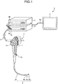
- FIG. 1 is a schematic diagram illustrating a schematic configuration of an endoscope system according to an embodiment of the present invention.
- FIG. 2 is a schematic diagram illustrating a schematic configuration of an optical connector for use in the endoscope system according to the embodiment of the present invention.
- FIG. 2 illustrates a state in which a first optical connector 11 and a second optical connector 12 are disconnected from each other.
- an endoscope system 1 includes an endoscope 2 to be introduced into a subject and configured to capture an inside of a body of the subject and generate an image signal of the inside of the subject, an information processing device 3 (external processor) configured to perform predetermined image processing on the image signal captured by the endoscope 2 and control the respective components of the endoscope system 1, a light source device 4 configured to generate illumination light for the endoscope 2, and a display device 5 configured to display an image corresponding to the image signal resulting from image processing performed by the information processing device 3.
- an information processing device 3 external processor
- a light source device 4 configured to generate illumination light for the endoscope 2
- a display device 5 configured to display an image corresponding to the image signal resulting from image processing performed by the information processing device 3.
- the endoscope 2 includes an insertion part 6 to be inserted into the subject, an operating unit 7, which is provided adjacent to a proximal end portion of the insertion part 6 and which is to be gripped by an operator, and flexible universal cord 8 extending from the operating unit 7.
- the insertion part 6 is constituted by an illumination fiber (light guide cable), an electric cable, an optical fiber, and the like.
- the insertion part 6 has a distal end portion 6a incorporating an image sensor, a bending portion 6b, which is freely bendable and constituted by a plurality of bending pieces, and a flexible tube portion 6c, which is flexible and provided on the proximal end side of the bending portion 6b.
- the distal end portion 6a is provided with an illumination portion for illuminating the inside of the subject via an illumination lens, an observation portion for capturing the inside of the subject, an aperture 6d through which a channel for a processing tool communicates, and an air/water nozzle (not illustrated).
- the image sensor located at an image forming position of an optical system for light collection and configured to receive light collected by the optical system, perform photoelectric conversion on the light into an electrical signal and perform predetermined signal processing on the electrical signal
- a transmission module 20 having a light emitting element 23 configured to convert an electrical signal containing image information input form the image sensor into an optical signal and transmit the optical signal to the information processing device 3 are arranged.
- the transmission module 20 holds and fixes an end of a first optical fiber 21, which transmits an optical signal output from the light emitting element 23, with a ferrule 22 therebetween.
- the operating unit 7 includes a bending nob 7a for bending the bending portion 6b upward, downward, leftward, and rightward, treatment tool insertion part 7b through which a treatment tool such as living body forceps or a laser knife is inserted into the body cavity of a subject, and a plurality of switches 7c for operation of peripheral devices such as the information processing device 3, the light source device 4, an air supply device, a water supply device, and a gas supply device.
- a treatment tool inserted through the treatment tool insertion part 7b passes through a treatment tool channel formed thereinside and comes out from the aperture 6d at the distal end of the insertion part 6.
- the universal cord 8 is constituted by an illumination fiber, an electric cable, the first optical fiber 21, and the like.
- the universal cord 8 branches at the proximal end into one end being a first connector 8a and the other proximal end being an illumination connector 8b.
- the first connector 8a is removably connected with a second connector 8c of the information processing device 3.
- the illumination connector 8b is removably connected with the light source device 4.
- the first connector 8a incorporates the first optical connector 11 for holding the first optical fiber 21, and the second connector 8c incorporates the second optical connector 12 for holding a second optical fiber 31.
- the information processing device 3 performs predetermined image processing on an image signal of the inside of the subject captured by an imaging unit at the distal end portion 6a of the endoscope 2.
- the information processing device 3 controls the respective components of the endoscope system 1 on the basis of various instruction signals transmitted from the switches 7c at the operating unit 7 of the endoscope 2 via the universal cord 8.
- the light source device 4 is constituted by a light source that emits light, a condenser lens, and the like.
- the light source device 4 emits light from the light source, and supplies the light as light for illuminating the inside of the subject to be imaged to the endoscope 2 connected via the illumination connector 8b and the illumination fiber and the first connector 8a of the universal cord 8 under the control of the information processing device 3.
- the display device 5 is constituted by a display using liquid crystal or organic electro-luminescence (EL), or the like.
- the display device 5 displays various information data, including images subjected to the predetermined image processing performed by the information processing device 3, via a video cable 5a. This allows the operator to operate the endoscope 2 while looking at an image (in-vivo image) displayed by the display device 5 to observe a desired position in the subject and determine characteristics.
- an optical connector 10 is constituted by the first optical connector 11 and the second optical connector 12.
- the first optical connector 11 is a connector on a transmitting side, and includes a ferrule 25 for holding the first optical fiber 21, a lens 26 and a lens 27 for increasing the beam diameter of an optical signal output from the end of the first optical fiber 21 to obtain parallel light, a sleeve 28 for positioning and holding the ferrule 25, the lens 26, and the lens 27, and a casing 29 accommodating the sleeve 28.
- the lens 26 and the lens 27 function as a first correction optical system.
- the second optical connector 12 is a connector on a receiving side, and includes a ferrule 32 for holding the second optical fiber 31, a lens 33 and a lens 34 for collecting the optical signal with the increased beam diameter output from the lens 27, a sleeve 35 for positioning and holding the lens 33 and the lens 34, and a casing 36 accommodating the sleeve 35 and the ferrule 32.
- the lens 33 and the lens 34 function as a second correction optical system.
- the first correction optical system and the second correction optical system are not limited to two lenses but may be constituted by one or three lenses.
- An optical fiber having a diameter, which is a core diameter, larger than that of the first optical fiber 21 is used for the second optical fiber 31.
- the second optical fiber 31 preferably has a core diameter that is 2.5 to 3.5 times the core diameter of the first optical fiber 21.
- the second optical fiber 31 may be either a graded index (GI) optical fiber having a core refractive index continuously changing quadratically in the radial direction or a step index (SI) optical fiber having a refractive index discontinuously changing only at a core-cladding interface.
- GI graded index
- SI step index
- a multicore fiber including a plurality of cores having approximately the same diameter as the first optical fiber 21 can be used.
- a protrusion 36a is formed at a connecting end of the casing 36 on the second optical connector 12 side, and the protrusion 36a is fitted into a recess 29a formed in the casing 29 on the first optical connector 11 side so that the first optical connector 11 and the second optical connector 12 are connected with each other.
- the first optical connector 11 and the second optical connector 12 incorporate the first connector 8a and the second connector 8c, respectively, and the first connector 8a is removed from the second connector 8c (the first optical connector 11 is also removed from the second optical connector 12) each time observation with the endoscope 2 is terminated. Repetition of the removal may cause adhesion of dirt to the surfaces of the lens 27 and the lens 34 and misalignment in the fitting of the first optical connector 11 and the second optical connector 12.
- FIG. 3 is a diagram for explaining transmission of an optical signal according to the embodiment of the present invention, in which a part (a) in FIG. 3 illustrates a case in which no fitting misalignment is caused and a part (b) in FIG. 3 illustrates a case in which dust 37 has adhered to the lens 27 and fitting misalignment of the first optical connector 11 and the second optical connector 12 is caused.
- An optical signal output from a core 21a of the first optical fiber 21 is increased in beam diameter and converted into parallel light by the lens 26 and the lens 27, and input to the lens 34 of the second optical connector 12.
- the lens 33 and the lens 34 collects the optical signal with the increase beam diameter output from the lens 27, and inputs the optical signal to a core 31a of the second optical fiber 31.
- an optical fiber having a core diameter larger than that of the first optical fiber 21 is used for the second optical fiber 31, which allows an optical signal to be input to the core 31a of the second optical fiber 31 even when the position to which the optical signal is collected is shifted to some extent owing to adhesion of dirt or fitting misalignment as in the part (b) in FIG. 3 , and thus allows transmission of an optical signal without causing attenuation of the optical signal.
- the light intensity of an optical signal is attenuated by about 40 to 50%; however, it is confirmed that, when the diameter of the second optical fiber 31 is 2.5 to 3.5 times that of the first optical fiber 21, the light intensity of an optical signal is not attenuated even when the optical axis of the optical connector is tilted by ⁇ 0.4°.
- a communication mode stabilizing unit 24 for smoothing optical beams is provided in the first optical fiber 21 for transmitting optical signals between the transmission module 20 and the first optical connector 11.
- the provision of the communication mode stabilizing unit 24 allows transmission of an optical signal by using a larger area of the core of the first optical fiber 21, and the communication mode is stabilized.
- the communication mode stabilizing unit 24 may employ an SGS type, a mandrel type, a microbend type, or the like. With the SGS type, the communication mode can be easily adjusted. With the mandrel type, no additional mechanism is needed. With the microbend type, removal of higher-order modes is more achieved than the other two types. Any one of these types may be employed depending on the need.
- a reception module 30 includes a light receiving element configured to convert the optical signal transmitted by the second optical fiber 31 into an electrical signal and output the electrical signal to the information processing device 3.
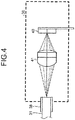
- FIG. 4 is a schematic diagram illustrating a schematic configuration of the reception module 30 according to the embodiment of the present invention.
- the reception module 30 includes a casing (not illustrated) for fixing a ferrule 38 for holding the end of the second optical fiber 31, and a lens 41 for collecting the optical signal output from the end of the second optical fiber 31.
- the lens 41 functions as a third correction optical system.
- the third correction optical system is not limited to one lens as in the present embodiment, but may be constituted by two or three lenses.
- a third correction optical system constituted by one lens allows miniaturization, and a third correction optical system constituted by two lenses facilitates optical axis alignment. If light collection is difficult with two or less lenses because the core diameter of the second optical fiber 31 is large, the third correction optical system may be constituted by three lenses to enable light collection.
- the lens configuration may be selected depending on the need. When three lenses are used, a lens adjacent to a light receiving element 40 may be directly connected with the light receiving element 40.
- the third correction optical system may be constituted by separate lens or lenses, or may be constituted by an end of the second optical fiber 31 formed in a tapered shape or a hemispherical shape to collect an optical signal.
- a tapered fiber with an end having a tapered shape or a lensed fiber with an end having a hemispherical shape, a spherical shape or a wedge shape can be used for the second optical fiber 31.
- Use of a tapered fiber or a lensed fiber reduces the space in which lenses are provided and allows miniaturization of the reception module 30.
- optical connectors may be provided in the operating unit 7.
- optical connectors may be provided at a plurality of positions in the endoscope system 1, such as in the operating unit 7, the first connector 8a, and the second connector 8c. In a case where a plurality of optical connectors are provided in the endoscope system 1, the diameters of optical fibers used therein are gradually increased from the insertion part 6 side toward the information processing device 3 side, which prevents attenuation of an optical signal.
Landscapes
- Health & Medical Sciences (AREA)
- Life Sciences & Earth Sciences (AREA)
- Physics & Mathematics (AREA)
- Surgery (AREA)
- Optics & Photonics (AREA)
- Engineering & Computer Science (AREA)
- Medical Informatics (AREA)
- General Health & Medical Sciences (AREA)
- Pathology (AREA)
- Nuclear Medicine, Radiotherapy & Molecular Imaging (AREA)
- Biomedical Technology (AREA)
- Heart & Thoracic Surgery (AREA)
- Biophysics (AREA)
- Molecular Biology (AREA)
- Animal Behavior & Ethology (AREA)
- Radiology & Medical Imaging (AREA)
- Public Health (AREA)
- Veterinary Medicine (AREA)
- General Physics & Mathematics (AREA)
- Astronomy & Astrophysics (AREA)
- Multimedia (AREA)
- Endoscopes (AREA)
- Instruments For Viewing The Inside Of Hollow Bodies (AREA)
- Optical Couplings Of Light Guides (AREA)
Abstract
Description
- The present invention relates to an endoscope system using an optical transmission system for transmitting image information.
- Conventionally, endoscope systems are used for observation of organs of subjects such as patients in the medical field. An endoscope system includes: an endoscope including an insertion part provided with an image sensor at a distal end, the insertion part having a flexible elongated shape and being inserted into a body cavity of a subject; an information processing device connected with the insertion part via a cable and a connector and configured to perform image processing on in-vivo images captured by the image sensor; and a display device configured to display the in-vivo images, for example.
- In recent years, image sensors with large numbers of pixels enabling observation with clearer image have been developed, and it has been considered to use the image sensors with large numbers of pixels for an endoscope. In addition, there are demands for reducing the diameter of the insertion part in view of facilitating introduction into a subject. Furthermore, a transmission system using optical fibers and optical waveguides has been employed in endoscope systems for high-speed and large-capacity signal transmission between an image sensor and an information processing device while achieving reduction in diameter of the insertion parts.
- As such a technique, an endoscope system in which an imaging unit converts an imaging signal into an optical signal by an E/O converter, and the optical signal is transmitted by an optical fiber and output to an O/E converter in a processor, is disclosed (for example, refer to Patent Literature 1).
- In addition, an endoscope system including a light source device capable of outputting a plurality of kinds of laser light, in which holder aligning unit for aligning the optical axes of a plurality of optical fibers, which transmit laser light, is provided in an optical connector for connecting the optical fibers is disclosed (for example, refer to Patent Literature 2).
-
- Patent Literature 1:
JP 2010-194037 A - Patent Literature 2:
JP 2011-152369 A - In
Patent Literatures - The present invention has been made in view of the above, and an object thereof is to provide an endoscope system capable of transmitting an optical signal even if some dirt is adhered to or fitting misalignment is present at an optical connector.
- To solve the above-described problem and achieve the object, an endoscope system according to the present invention includes: an image sensor configured to image a subject; a transmission module including a first photoelectric element configured to convert an imaging signal output from the image sensor into an optical signal and output the optical signal; a first optical fiber configured to transmit the optical signal output from the first photoelectric element; a first optical connector configured to hold an end of the first optical fiber connected with the first photoelectric element, the end being opposite to an end connected with the first photoelectric element; a second optical connector removably connected with the first optical connector; a second optical fiber configured to transmit the optical signal output from the first optical fiber, the second optical fiber being held by the second optical connector and having a core diameter larger than a core diameter of the first optical fiber; a reception module including a second photoelectric element configured to convert the optical signal transmitted by the second optical fiber into an electrical signal and output the electrical signal; a first correction optical system incorporated in the first optical connector and configured to increase a beam diameter of the optical signal output from the end of the first optical fiber; and a second correction optical system incorporated in the second optical connector and configured to collect the optical signal output from the first correction optical system.
- Moreover, in the above-described endoscope system according to the present invention, the first optical fiber includes a communication mode stabilizing unit configured to smooth an optical beam transmitted by the first optical fiber.
- Moreover, in the above-described endoscope system according to the present invention, the second optical fiber is a multicore fiber.
- Moreover, in the above-described endoscope system according to the present invention, the reception module includes a third correction optical system configured to collect the optical signal output from an end of the second optical fiber.
- Moreover, in the above-described endoscope system according to the present invention, the first correction optical system, the second correction optical system, and the third correction optical system each include one or more lenses.
- Moreover, in the above-described endoscope system according to the present invention, an end of the second optical fiber is an optical collecting part in a tapered shape, a hemispherical shape, a spherical shape or a wedge shape to collect the output optical signal.
- According to the present invention, the core diameter of an optical fiber on a receiving side is larger than that of an optical fiber on a transmitting side, which are connected by an optical connector, which prevents attenuation of an optical signal and allows normal transmission of the optical signal even when dirt is adhered to or fitting misalignment is caused at the optical connector part.
-
-
FIG. 1 is a schematic diagram illustrating a schematic configuration of an endoscope system according to an embodiment of the present invention. -
FIG. 2 is a schematic diagram illustrating a schematic configuration of an optical connector to for use in the endoscope system according to the embodiment of the present invention. -
FIG. 3 is a diagram illustrating transmission of an optical signal according to the embodiment of the present invention. -
FIG. 4 is a schematic diagram illustrating a schematic configuration of a reception module according to the embodiment of the present invention. - In the description below, an endoscope system, which is a mode for carrying out the present invention (hereinafter referred to as an "embodiment"), will be described. Note that the present invention is not limited to the embodiment. In depiction of the drawings, the same components will be designated by the same reference numerals.
-
FIG. 1 is a schematic diagram illustrating a schematic configuration of an endoscope system according to an embodiment of the present invention.FIG. 2 is a schematic diagram illustrating a schematic configuration of an optical connector for use in the endoscope system according to the embodiment of the present invention.FIG. 2 illustrates a state in which a firstoptical connector 11 and a secondoptical connector 12 are disconnected from each other. - As illustrated in
FIGS. 1 and2 , anendoscope system 1 according to the embodiment includes anendoscope 2 to be introduced into a subject and configured to capture an inside of a body of the subject and generate an image signal of the inside of the subject, an information processing device 3 (external processor) configured to perform predetermined image processing on the image signal captured by theendoscope 2 and control the respective components of theendoscope system 1, a light source device 4 configured to generate illumination light for theendoscope 2, and adisplay device 5 configured to display an image corresponding to the image signal resulting from image processing performed by theinformation processing device 3. - The
endoscope 2 includes aninsertion part 6 to be inserted into the subject, an operating unit 7, which is provided adjacent to a proximal end portion of theinsertion part 6 and which is to be gripped by an operator, and flexibleuniversal cord 8 extending from the operating unit 7. - The
insertion part 6 is constituted by an illumination fiber (light guide cable), an electric cable, an optical fiber, and the like. Theinsertion part 6 has adistal end portion 6a incorporating an image sensor, abending portion 6b, which is freely bendable and constituted by a plurality of bending pieces, and aflexible tube portion 6c, which is flexible and provided on the proximal end side of thebending portion 6b. Thedistal end portion 6a is provided with an illumination portion for illuminating the inside of the subject via an illumination lens, an observation portion for capturing the inside of the subject, anaperture 6d through which a channel for a processing tool communicates, and an air/water nozzle (not illustrated). - At the
distal end portion 6a, the image sensor located at an image forming position of an optical system for light collection and configured to receive light collected by the optical system, perform photoelectric conversion on the light into an electrical signal and perform predetermined signal processing on the electrical signal, and atransmission module 20 having alight emitting element 23 configured to convert an electrical signal containing image information input form the image sensor into an optical signal and transmit the optical signal to theinformation processing device 3 are arranged. Thetransmission module 20 holds and fixes an end of a firstoptical fiber 21, which transmits an optical signal output from thelight emitting element 23, with aferrule 22 therebetween. - The operating unit 7 includes a
bending nob 7a for bending thebending portion 6b upward, downward, leftward, and rightward, treatmenttool insertion part 7b through which a treatment tool such as living body forceps or a laser knife is inserted into the body cavity of a subject, and a plurality ofswitches 7c for operation of peripheral devices such as theinformation processing device 3, the light source device 4, an air supply device, a water supply device, and a gas supply device. A treatment tool inserted through the treatmenttool insertion part 7b passes through a treatment tool channel formed thereinside and comes out from theaperture 6d at the distal end of theinsertion part 6. - The
universal cord 8 is constituted by an illumination fiber, an electric cable, the firstoptical fiber 21, and the like. Theuniversal cord 8 branches at the proximal end into one end being afirst connector 8a and the other proximal end being anillumination connector 8b. Thefirst connector 8a is removably connected with asecond connector 8c of theinformation processing device 3. Theillumination connector 8b is removably connected with the light source device 4. Thefirst connector 8a incorporates the firstoptical connector 11 for holding the firstoptical fiber 21, and thesecond connector 8c incorporates the secondoptical connector 12 for holding a secondoptical fiber 31. - The
information processing device 3 performs predetermined image processing on an image signal of the inside of the subject captured by an imaging unit at thedistal end portion 6a of theendoscope 2. Theinformation processing device 3 controls the respective components of theendoscope system 1 on the basis of various instruction signals transmitted from theswitches 7c at the operating unit 7 of theendoscope 2 via theuniversal cord 8. - The light source device 4 is constituted by a light source that emits light, a condenser lens, and the like. The light source device 4 emits light from the light source, and supplies the light as light for illuminating the inside of the subject to be imaged to the
endoscope 2 connected via theillumination connector 8b and the illumination fiber and thefirst connector 8a of theuniversal cord 8 under the control of theinformation processing device 3. - The
display device 5 is constituted by a display using liquid crystal or organic electro-luminescence (EL), or the like. Thedisplay device 5 displays various information data, including images subjected to the predetermined image processing performed by theinformation processing device 3, via avideo cable 5a. This allows the operator to operate theendoscope 2 while looking at an image (in-vivo image) displayed by thedisplay device 5 to observe a desired position in the subject and determine characteristics. - As illustrated in
FIG. 2 , anoptical connector 10 is constituted by the firstoptical connector 11 and the secondoptical connector 12. The firstoptical connector 11 is a connector on a transmitting side, and includes aferrule 25 for holding the firstoptical fiber 21, alens 26 and alens 27 for increasing the beam diameter of an optical signal output from the end of the firstoptical fiber 21 to obtain parallel light, asleeve 28 for positioning and holding theferrule 25, thelens 26, and thelens 27, and acasing 29 accommodating thesleeve 28. In the present embodiment, thelens 26 and thelens 27 function as a first correction optical system. - The second
optical connector 12 is a connector on a receiving side, and includes aferrule 32 for holding the secondoptical fiber 31, alens 33 and alens 34 for collecting the optical signal with the increased beam diameter output from thelens 27, asleeve 35 for positioning and holding thelens 33 and thelens 34, and acasing 36 accommodating thesleeve 35 and theferrule 32. In the present embodiment, thelens 33 and thelens 34 function as a second correction optical system. The first correction optical system and the second correction optical system are not limited to two lenses but may be constituted by one or three lenses. - An optical fiber having a diameter, which is a core diameter, larger than that of the first
optical fiber 21 is used for the secondoptical fiber 31. The secondoptical fiber 31 preferably has a core diameter that is 2.5 to 3.5 times the core diameter of the firstoptical fiber 21. The secondoptical fiber 31 may be either a graded index (GI) optical fiber having a core refractive index continuously changing quadratically in the radial direction or a step index (SI) optical fiber having a refractive index discontinuously changing only at a core-cladding interface. Alternatively, a multicore fiber including a plurality of cores having approximately the same diameter as the firstoptical fiber 21 can be used. - A
protrusion 36a is formed at a connecting end of thecasing 36 on the secondoptical connector 12 side, and theprotrusion 36a is fitted into arecess 29a formed in thecasing 29 on the firstoptical connector 11 side so that the firstoptical connector 11 and the secondoptical connector 12 are connected with each other. - The first
optical connector 11 and the secondoptical connector 12 incorporate thefirst connector 8a and thesecond connector 8c, respectively, and thefirst connector 8a is removed from thesecond connector 8c (the firstoptical connector 11 is also removed from the second optical connector 12) each time observation with theendoscope 2 is terminated. Repetition of the removal may cause adhesion of dirt to the surfaces of thelens 27 and thelens 34 and misalignment in the fitting of the firstoptical connector 11 and the secondoptical connector 12. -
FIG. 3 is a diagram for explaining transmission of an optical signal according to the embodiment of the present invention, in which a part (a) inFIG. 3 illustrates a case in which no fitting misalignment is caused and a part (b) inFIG. 3 illustrates a case in whichdust 37 has adhered to thelens 27 and fitting misalignment of the firstoptical connector 11 and the secondoptical connector 12 is caused. An optical signal output from acore 21a of the firstoptical fiber 21 is increased in beam diameter and converted into parallel light by thelens 26 and thelens 27, and input to thelens 34 of the secondoptical connector 12. Thelens 33 and thelens 34 collects the optical signal with the increase beam diameter output from thelens 27, and inputs the optical signal to acore 31a of the secondoptical fiber 31. While the optical light is collected to substantially the central part of the core 31a of the secondoptical fiber 31 in the part (a) inFIG. 3 in which no fitting misalignment is caused, the position to which the optical signal is collected is shifted in the case where fitting misalignment is caused as illustrated in the part (b) inFIG. 3 . In the embodiment of the present invention, an optical fiber having a core diameter larger than that of the firstoptical fiber 21 is used for the secondoptical fiber 31, which allows an optical signal to be input to thecore 31a of the secondoptical fiber 31 even when the position to which the optical signal is collected is shifted to some extent owing to adhesion of dirt or fitting misalignment as in the part (b) inFIG. 3 , and thus allows transmission of an optical signal without causing attenuation of the optical signal. - When optical fibers having the same diameter are used for the first
optical fiber 21 and the secondoptical fiber 31 and when the optical axis of an optical connector is tilted by ±0.2°, the light intensity of an optical signal is attenuated by about 40 to 50%; however, it is confirmed that, when the diameter of the secondoptical fiber 31 is 2.5 to 3.5 times that of the firstoptical fiber 21, the light intensity of an optical signal is not attenuated even when the optical axis of the optical connector is tilted by ±0.4°. - In addition, a communication
mode stabilizing unit 24 for smoothing optical beams is provided in the firstoptical fiber 21 for transmitting optical signals between thetransmission module 20 and the firstoptical connector 11. The provision of the communicationmode stabilizing unit 24 allows transmission of an optical signal by using a larger area of the core of the firstoptical fiber 21, and the communication mode is stabilized. The communicationmode stabilizing unit 24 may employ an SGS type, a mandrel type, a microbend type, or the like. With the SGS type, the communication mode can be easily adjusted. With the mandrel type, no additional mechanism is needed. With the microbend type, removal of higher-order modes is more achieved than the other two types. Any one of these types may be employed depending on the need. - A
reception module 30 includes a light receiving element configured to convert the optical signal transmitted by the secondoptical fiber 31 into an electrical signal and output the electrical signal to theinformation processing device 3.FIG. 4 is a schematic diagram illustrating a schematic configuration of thereception module 30 according to the embodiment of the present invention. Thereception module 30 includes a casing (not illustrated) for fixing aferrule 38 for holding the end of the secondoptical fiber 31, and alens 41 for collecting the optical signal output from the end of the secondoptical fiber 31. In the present embodiment, thelens 41 functions as a third correction optical system. The third correction optical system is not limited to one lens as in the present embodiment, but may be constituted by two or three lenses. A third correction optical system constituted by one lens allows miniaturization, and a third correction optical system constituted by two lenses facilitates optical axis alignment. If light collection is difficult with two or less lenses because the core diameter of the secondoptical fiber 31 is large, the third correction optical system may be constituted by three lenses to enable light collection. The lens configuration may be selected depending on the need. When three lenses are used, a lens adjacent to alight receiving element 40 may be directly connected with thelight receiving element 40. - Furthermore, the third correction optical system may be constituted by separate lens or lenses, or may be constituted by an end of the second
optical fiber 31 formed in a tapered shape or a hemispherical shape to collect an optical signal. A tapered fiber with an end having a tapered shape or a lensed fiber with an end having a hemispherical shape, a spherical shape or a wedge shape can be used for the secondoptical fiber 31. Use of a tapered fiber or a lensed fiber reduces the space in which lenses are provided and allows miniaturization of thereception module 30. - While the first
optical connector 11 is incorporated in thefirst connector 8a and the secondoptical connector 12 is incorporated in thesecond connector 8c in the embodiment described above, an optical connector may be provided in the operating unit 7. Furthermore, optical connectors may be provided at a plurality of positions in theendoscope system 1, such as in the operating unit 7, thefirst connector 8a, and thesecond connector 8c. In a case where a plurality of optical connectors are provided in theendoscope system 1, the diameters of optical fibers used therein are gradually increased from theinsertion part 6 side toward theinformation processing device 3 side, which prevents attenuation of an optical signal. -
- 1
- ENDOSCOPE SYSTEM
- 2
- ENDOSCOPE
- 3
- INFORMATION PROCESSING DEVICE
- 4
- LIGHT SOURCE DEVICE
- 5
- DISPLAY DEVICE
- 6
- INSERTION PART
- 6a
- DISTAL END PORTION
- 6b
- BENDING PORTION
- 6c
- FLEXIBLE TUBE PORTION
- 6d
- APERTURE
- 7
- OPERATING UNIT
- 7a
- BENDING NOB
- 7b
- TREATMENT TOOL INSERTION PART
- 7c
- SWITCHES
- 8
- UNIVERSAL CORD
- 8a
- FIRST CONNECTOR
- 8b
- ILLUMINATION CONNECTOR
- 8c
- SECOND CONNECTOR
- 10
- OPTICAL CONNECTOR
- 11
- FIRST OPTICAL CONNECTOR
- 12
- SECOND OPTICAL CONNECTOR
- 20
- TRANSMISSION MODULE
- 21
- FIRST OPTICAL FIBER
- 21a, 31a
- CORE
- 22, 25, 32, 38
- FERRULE
- 23
- LIGHT EMITTING ELEMENT
- 24
- COMMUNICATION MODE STABILIZING UNIT
- 26, 27, 33, 34, 41
- LENS
- 28, 35
- SLEEVE
- 29, 36
- CASING
- 29a
- RECESS
- 30
- RECEPTION MODULE
- 31
- SECOND OPTICAL FIBER
- 36a
- PROTRUSION
- 40
- LIGHT RECEIVING ELEMENT
Claims (6)
- An endoscope system comprising:an image sensor configured to image a subject;a transmission module including a first photoelectric element configured to convert an imaging signal output from the image sensor into an optical signal and output the optical signal;a first optical fiber configured to transmit the optical signal output from the first photoelectric element;a first optical connector configured to hold an end of the first optical fiber connected with the first photoelectric element, the end being opposite to an end connected with the first photoelectric element;a second optical connector removably connected with the first optical connector;a second optical fiber configured to transmit the optical signal output from the first optical fiber, the second optical fiber being held by the second optical connector and having a core diameter larger than a core diameter of the first optical fiber;a reception module including a second photoelectric element configured to convert the optical signal transmitted by the second optical fiber into an electrical signal and output the electrical signal;a first correction optical system incorporated in the first optical connector and configured to increase a beam diameter of the optical signal output from the end of the first optical fiber; anda second correction optical system incorporated in the second optical connector and configured to collect the optical signal output from the first correction optical system.
- The endoscope system according to claim 1, wherein the first optical fiber includes a communication mode stabilizing unit configured to smooth an optical beam transmitted by the first optical fiber.
- The endoscope system according to claim 1, wherein the second optical fiber is a multicore fiber.
- The endoscope system according to claim 1, wherein the reception module includes a third correction optical system configured to collect the optical signal output from an end of the second optical fiber.
- The endoscope system according to claim 4, wherein the first correction optical system, the second correction optical system, and the third correction optical system each include one or more lenses.
- The endoscope system according to claim 1, wherein an end of the second optical fiber is an optical collecting part in a tapered shape, a hemispherical shape, a spherical shape or a wedge shape to collect the output optical signal.
Applications Claiming Priority (2)
| Application Number | Priority Date | Filing Date | Title |
|---|---|---|---|
| JP2015088514 | 2015-04-23 | ||
| PCT/JP2016/055195 WO2016170838A1 (en) | 2015-04-23 | 2016-02-23 | Endoscope system |
Publications (1)
| Publication Number | Publication Date |
|---|---|
| EP3287064A1 true EP3287064A1 (en) | 2018-02-28 |
Family
ID=57144591
Family Applications (1)
| Application Number | Title | Priority Date | Filing Date |
|---|---|---|---|
| EP16782860.7A Withdrawn EP3287064A1 (en) | 2015-04-23 | 2016-02-23 | Endoscope system |
Country Status (5)
| Country | Link |
|---|---|
| US (1) | US10687696B2 (en) |
| EP (1) | EP3287064A1 (en) |
| JP (1) | JP6177463B2 (en) |
| CN (1) | CN107529967B (en) |
| WO (1) | WO2016170838A1 (en) |
Families Citing this family (8)
| Publication number | Priority date | Publication date | Assignee | Title |
|---|---|---|---|---|
| US11495942B2 (en) | 2016-10-28 | 2022-11-08 | Nlight, Inc. | Method, system and apparatus for higher order mode suppression |
| JPWO2018163498A1 (en) * | 2017-03-08 | 2020-05-14 | ソニー・オリンパスメディカルソリューションズ株式会社 | Medical device and method of manufacturing medical device |
| US11063404B1 (en) | 2018-09-13 | 2021-07-13 | Nlight, Inc. | Bidirectionally emitting semiconductor laser devices |
| US11824323B1 (en) | 2018-12-06 | 2023-11-21 | Nlight, Inc. | Diode laser package for bidirectionally emitting semiconductor laser devices |
| CN110764248B (en) * | 2019-09-26 | 2021-09-24 | 浙江大学 | A probe with optimized depth of focus, working distance and axial intensity uniformity |
| CN115735147B (en) * | 2020-07-30 | 2025-09-09 | 富士胶片株式会社 | Imaging device and endoscope |
| CN115670354A (en) * | 2021-07-27 | 2023-02-03 | 深圳迈瑞生物医疗电子股份有限公司 | Optical connector and endoscope camera system |
| CN118452792B (en) * | 2024-07-01 | 2025-03-21 | 美希艾精密仪器(苏州)有限公司 | An optoelectronic connection component for connecting an optical imaging system and a handheld terminal |
Family Cites Families (25)
| Publication number | Priority date | Publication date | Assignee | Title |
|---|---|---|---|---|
| US4421383A (en) * | 1980-01-17 | 1983-12-20 | Gte Laboratories Incorporated | Optical fiber connectors |
| JPS56146103A (en) * | 1980-04-15 | 1981-11-13 | Mitsubishi Electric Corp | Optical multidistributor |
| JPS5936213A (en) * | 1982-08-23 | 1984-02-28 | Agency Of Ind Science & Technol | Optical fiber connector |
| US4563057A (en) * | 1982-08-31 | 1986-01-07 | The United States Of America As Represented By The Secretary Of The Air Force | Fiber optic cable connector |
| JPH01234804A (en) * | 1988-03-16 | 1989-09-20 | Toshiba Corp | Method of connecting optical fibers |
| US5039193A (en) * | 1990-04-03 | 1991-08-13 | Focal Technologies Incorporated | Fibre optic single mode rotary joint |
| JPH04101508U (en) * | 1991-01-30 | 1992-09-02 | ホーヤ株式会社 | optical connector |
| US5293438A (en) * | 1991-09-21 | 1994-03-08 | Namiki Precision Jewel Co., Ltd. | Microlensed optical terminals and optical system equipped therewith, and methods for their manufacture, especially an optical coupling method and optical coupler for use therewith |
| JP3135979B2 (en) * | 1992-04-06 | 2001-02-19 | 並木精密宝石株式会社 | Optical fiber terminal optical device with micro lens |
| JP3313559B2 (en) * | 1995-12-20 | 2002-08-12 | 三菱電機株式会社 | Light trigger thyristor |
| JP2001201657A (en) * | 2000-01-21 | 2001-07-27 | Nippon Sheet Glass Co Ltd | Optical device |
| US6632025B2 (en) * | 2001-07-05 | 2003-10-14 | Corning Incorporated | High power expanded beam connector and methods for using and making the high power expanded beam connector |
| US6655850B2 (en) * | 2001-07-05 | 2003-12-02 | Corning Incorporated | Hybrid fiber expanded beam connector and methods for using and making the hybrid fiber expanded beam connector |
| US20100141732A1 (en) * | 2005-07-25 | 2010-06-10 | Fujifilm Corporation | Image recording device and method |
| JP2007273842A (en) * | 2006-03-31 | 2007-10-18 | Miyachi Technos Corp | Fiber laser oscillator and fiber laser processing apparatus |
| JP5224445B2 (en) * | 2008-03-17 | 2013-07-03 | 富士フイルム株式会社 | Laser light source device |
| JP2010101669A (en) * | 2008-10-22 | 2010-05-06 | Nec Corp | Device and method for measuring band of multimode optical fiber |
| US7775725B2 (en) * | 2008-10-29 | 2010-08-17 | Tyco Electronics Corporation | Single-channel expanded beam connector |
| JP2010194037A (en) * | 2009-02-24 | 2010-09-09 | Olympus Corp | Electronic endoscope |
| CN101988977A (en) * | 2009-07-31 | 2011-03-23 | 鸿富锦精密工业(深圳)有限公司 | Optical fiber coupling connector |
| JP5277187B2 (en) | 2010-01-28 | 2013-08-28 | 富士フイルム株式会社 | Medical equipment and endoscope device |
| TWI490577B (en) * | 2011-07-07 | 2015-07-01 | Hon Hai Prec Ind Co Ltd | Adapter and optical fiber connector |
| JP2013156337A (en) * | 2012-01-27 | 2013-08-15 | Mitsubishi Pencil Co Ltd | Optical coupling member and optical connector |
| CN102946045B (en) * | 2012-11-30 | 2015-01-14 | 清华大学 | Fiber laser pump coupler |
| CN107735708B (en) * | 2015-07-02 | 2019-10-25 | 奥林巴斯株式会社 | Optical signal transmission system and optical socket |
-
2016
- 2016-02-23 WO PCT/JP2016/055195 patent/WO2016170838A1/en not_active Ceased
- 2016-02-23 CN CN201680020376.6A patent/CN107529967B/en active Active
- 2016-02-23 EP EP16782860.7A patent/EP3287064A1/en not_active Withdrawn
- 2016-02-23 JP JP2016567940A patent/JP6177463B2/en active Active
-
2017
- 2017-10-02 US US15/722,052 patent/US10687696B2/en active Active
Also Published As
| Publication number | Publication date |
|---|---|
| WO2016170838A1 (en) | 2016-10-27 |
| CN107529967A (en) | 2018-01-02 |
| US20180035877A1 (en) | 2018-02-08 |
| JPWO2016170838A1 (en) | 2017-04-27 |
| CN107529967B (en) | 2020-08-11 |
| JP6177463B2 (en) | 2017-08-09 |
| US10687696B2 (en) | 2020-06-23 |
Similar Documents
| Publication | Publication Date | Title |
|---|---|---|
| US10687696B2 (en) | Endoscope system with communication mode stabilizing unit | |
| US9261662B2 (en) | Photoelectric conversion connector, optical transmission module, imaging apparatus, and endoscope | |
| US20190183324A1 (en) | Digital disposable endoscope system | |
| US8917315B2 (en) | Imaging module | |
| JP7143492B2 (en) | transmission cable | |
| EP2837324A1 (en) | Endoscope | |
| JP6062076B2 (en) | Unit, method of connecting module and connector, and endoscope system | |
| RU146337U1 (en) | LASER VIDEO ENDOSCOPE | |
| US9445709B2 (en) | Imaging unit and imaging system | |
| CN116262028A (en) | Relay adapters and plug-in device systems | |
| US9537574B2 (en) | Optical transmitting and receiving unit | |
| US20230148839A1 (en) | Disposable endoscope | |
| JP6664943B2 (en) | Endoscope system and information processing device | |
| JP2021166647A (en) | Endoscope apparatus | |
| JP2016209084A (en) | Endoscope system | |
| JP2018029885A (en) | Electronic scope, electronic scope system, and lens unit | |
| JP2015177920A (en) | Endoscope extention apparatus | |
| JP2009237424A (en) | Lens unit for probe and assembling method therefor |
Legal Events
| Date | Code | Title | Description |
|---|---|---|---|
| STAA | Information on the status of an ep patent application or granted ep patent |
Free format text: STATUS: THE INTERNATIONAL PUBLICATION HAS BEEN MADE |
|
| PUAI | Public reference made under article 153(3) epc to a published international application that has entered the european phase |
Free format text: ORIGINAL CODE: 0009012 |
|
| STAA | Information on the status of an ep patent application or granted ep patent |
Free format text: STATUS: REQUEST FOR EXAMINATION WAS MADE |
|
| 17P | Request for examination filed |
Effective date: 20171116 |
|
| AK | Designated contracting states |
Kind code of ref document: A1 Designated state(s): AL AT BE BG CH CY CZ DE DK EE ES FI FR GB GR HR HU IE IS IT LI LT LU LV MC MK MT NL NO PL PT RO RS SE SI SK SM TR |
|
| AX | Request for extension of the european patent |
Extension state: BA ME |
|
| DAV | Request for validation of the european patent (deleted) | ||
| DAX | Request for extension of the european patent (deleted) | ||
| STAA | Information on the status of an ep patent application or granted ep patent |
Free format text: STATUS: THE APPLICATION IS DEEMED TO BE WITHDRAWN |
|
| 18D | Application deemed to be withdrawn |
Effective date: 20180901 |