JP7143492B2 - transmission cable - Google Patents
transmission cable Download PDFInfo
- Publication number
- JP7143492B2 JP7143492B2 JP2021124521A JP2021124521A JP7143492B2 JP 7143492 B2 JP7143492 B2 JP 7143492B2 JP 2021124521 A JP2021124521 A JP 2021124521A JP 2021124521 A JP2021124521 A JP 2021124521A JP 7143492 B2 JP7143492 B2 JP 7143492B2
- Authority
- JP
- Japan
- Prior art keywords
- connector
- optical
- optical fiber
- substrate
- transmission cable
- Prior art date
- Legal status (The legal status is an assumption and is not a legal conclusion. Google has not performed a legal analysis and makes no representation as to the accuracy of the status listed.)
- Active
Links
Images


Classifications
-
- G—PHYSICS
- G02—OPTICS
- G02B—OPTICAL ELEMENTS, SYSTEMS OR APPARATUS
- G02B6/00—Light guides; Structural details of arrangements comprising light guides and other optical elements, e.g. couplings
- G02B6/24—Coupling light guides
- G02B6/36—Mechanical coupling means
- G02B6/38—Mechanical coupling means having fibre to fibre mating means
- G02B6/3807—Dismountable connectors, i.e. comprising plugs
- G02B6/3873—Connectors using guide surfaces for aligning ferrule ends, e.g. tubes, sleeves, V-grooves, rods, pins, balls
- G02B6/3874—Connectors using guide surfaces for aligning ferrule ends, e.g. tubes, sleeves, V-grooves, rods, pins, balls using tubes, sleeves to align ferrules
- G02B6/3877—Split sleeves
-
- A—HUMAN NECESSITIES
- A61—MEDICAL OR VETERINARY SCIENCE; HYGIENE
- A61B—DIAGNOSIS; SURGERY; IDENTIFICATION
- A61B1/00—Instruments for performing medical examinations of the interior of cavities or tubes of the body by visual or photographical inspection, e.g. endoscopes; Illuminating arrangements therefor
- A61B1/00002—Operational features of endoscopes
- A61B1/00004—Operational features of endoscopes characterised by electronic signal processing
- A61B1/00009—Operational features of endoscopes characterised by electronic signal processing of image signals during a use of endoscope
-
- A—HUMAN NECESSITIES
- A61—MEDICAL OR VETERINARY SCIENCE; HYGIENE
- A61B—DIAGNOSIS; SURGERY; IDENTIFICATION
- A61B1/00—Instruments for performing medical examinations of the interior of cavities or tubes of the body by visual or photographical inspection, e.g. endoscopes; Illuminating arrangements therefor
- A61B1/00002—Operational features of endoscopes
- A61B1/00011—Operational features of endoscopes characterised by signal transmission
- A61B1/00013—Operational features of endoscopes characterised by signal transmission using optical means
-
- A—HUMAN NECESSITIES
- A61—MEDICAL OR VETERINARY SCIENCE; HYGIENE
- A61B—DIAGNOSIS; SURGERY; IDENTIFICATION
- A61B1/00—Instruments for performing medical examinations of the interior of cavities or tubes of the body by visual or photographical inspection, e.g. endoscopes; Illuminating arrangements therefor
- A61B1/00002—Operational features of endoscopes
- A61B1/00011—Operational features of endoscopes characterised by signal transmission
- A61B1/00018—Operational features of endoscopes characterised by signal transmission using electrical cables
-
- A—HUMAN NECESSITIES
- A61—MEDICAL OR VETERINARY SCIENCE; HYGIENE
- A61B—DIAGNOSIS; SURGERY; IDENTIFICATION
- A61B1/00—Instruments for performing medical examinations of the interior of cavities or tubes of the body by visual or photographical inspection, e.g. endoscopes; Illuminating arrangements therefor
- A61B1/00064—Constructional details of the endoscope body
- A61B1/0011—Manufacturing of endoscope parts
-
- A—HUMAN NECESSITIES
- A61—MEDICAL OR VETERINARY SCIENCE; HYGIENE
- A61B—DIAGNOSIS; SURGERY; IDENTIFICATION
- A61B1/00—Instruments for performing medical examinations of the interior of cavities or tubes of the body by visual or photographical inspection, e.g. endoscopes; Illuminating arrangements therefor
- A61B1/00112—Connection or coupling means
- A61B1/00114—Electrical cables in or with an endoscope
-
- A—HUMAN NECESSITIES
- A61—MEDICAL OR VETERINARY SCIENCE; HYGIENE
- A61B—DIAGNOSIS; SURGERY; IDENTIFICATION
- A61B1/00—Instruments for performing medical examinations of the interior of cavities or tubes of the body by visual or photographical inspection, e.g. endoscopes; Illuminating arrangements therefor
- A61B1/00112—Connection or coupling means
- A61B1/00117—Optical cables in or with an endoscope
-
- A—HUMAN NECESSITIES
- A61—MEDICAL OR VETERINARY SCIENCE; HYGIENE
- A61B—DIAGNOSIS; SURGERY; IDENTIFICATION
- A61B1/00—Instruments for performing medical examinations of the interior of cavities or tubes of the body by visual or photographical inspection, e.g. endoscopes; Illuminating arrangements therefor
- A61B1/00112—Connection or coupling means
- A61B1/00121—Connectors, fasteners and adapters, e.g. on the endoscope handle
- A61B1/00124—Connectors, fasteners and adapters, e.g. on the endoscope handle electrical, e.g. electrical plug-and-socket connection
-
- A—HUMAN NECESSITIES
- A61—MEDICAL OR VETERINARY SCIENCE; HYGIENE
- A61B—DIAGNOSIS; SURGERY; IDENTIFICATION
- A61B1/00—Instruments for performing medical examinations of the interior of cavities or tubes of the body by visual or photographical inspection, e.g. endoscopes; Illuminating arrangements therefor
- A61B1/00112—Connection or coupling means
- A61B1/00121—Connectors, fasteners and adapters, e.g. on the endoscope handle
- A61B1/00126—Connectors, fasteners and adapters, e.g. on the endoscope handle optical, e.g. for light supply cables
-
- A—HUMAN NECESSITIES
- A61—MEDICAL OR VETERINARY SCIENCE; HYGIENE
- A61B—DIAGNOSIS; SURGERY; IDENTIFICATION
- A61B1/00—Instruments for performing medical examinations of the interior of cavities or tubes of the body by visual or photographical inspection, e.g. endoscopes; Illuminating arrangements therefor
- A61B1/00163—Optical arrangements
- A61B1/00165—Optical arrangements with light-conductive means, e.g. fibre optics
-
- A—HUMAN NECESSITIES
- A61—MEDICAL OR VETERINARY SCIENCE; HYGIENE
- A61B—DIAGNOSIS; SURGERY; IDENTIFICATION
- A61B1/00—Instruments for performing medical examinations of the interior of cavities or tubes of the body by visual or photographical inspection, e.g. endoscopes; Illuminating arrangements therefor
- A61B1/04—Instruments for performing medical examinations of the interior of cavities or tubes of the body by visual or photographical inspection, e.g. endoscopes; Illuminating arrangements therefor combined with photographic or television appliances
- A61B1/05—Instruments for performing medical examinations of the interior of cavities or tubes of the body by visual or photographical inspection, e.g. endoscopes; Illuminating arrangements therefor combined with photographic or television appliances characterised by the image sensor, e.g. camera, being in the distal end portion
- A61B1/051—Details of CCD assembly
-
- G—PHYSICS
- G02—OPTICS
- G02B—OPTICAL ELEMENTS, SYSTEMS OR APPARATUS
- G02B23/00—Telescopes, e.g. binoculars; Periscopes; Instruments for viewing the inside of hollow bodies; Viewfinders; Optical aiming or sighting devices
- G02B23/24—Instruments or systems for viewing the inside of hollow bodies, e.g. fibrescopes
-
- H—ELECTRICITY
- H04—ELECTRIC COMMUNICATION TECHNIQUE
- H04N—PICTORIAL COMMUNICATION, e.g. TELEVISION
- H04N7/00—Television systems
- H04N7/18—Closed-circuit television [CCTV] systems, i.e. systems in which the video signal is not broadcast
- H04N7/183—Closed-circuit television [CCTV] systems, i.e. systems in which the video signal is not broadcast for receiving images from a single remote source
-
- H—ELECTRICITY
- H04—ELECTRIC COMMUNICATION TECHNIQUE
- H04N—PICTORIAL COMMUNICATION, e.g. TELEVISION
- H04N7/00—Television systems
- H04N7/22—Adaptations for optical transmission
-
- A—HUMAN NECESSITIES
- A61—MEDICAL OR VETERINARY SCIENCE; HYGIENE
- A61B—DIAGNOSIS; SURGERY; IDENTIFICATION
- A61B1/00—Instruments for performing medical examinations of the interior of cavities or tubes of the body by visual or photographical inspection, e.g. endoscopes; Illuminating arrangements therefor
- A61B1/04—Instruments for performing medical examinations of the interior of cavities or tubes of the body by visual or photographical inspection, e.g. endoscopes; Illuminating arrangements therefor combined with photographic or television appliances
- A61B1/044—Instruments for performing medical examinations of the interior of cavities or tubes of the body by visual or photographical inspection, e.g. endoscopes; Illuminating arrangements therefor combined with photographic or television appliances for absorption imaging
-
- G—PHYSICS
- G02—OPTICS
- G02B—OPTICAL ELEMENTS, SYSTEMS OR APPARATUS
- G02B6/00—Light guides; Structural details of arrangements comprising light guides and other optical elements, e.g. couplings
- G02B6/24—Coupling light guides
- G02B6/36—Mechanical coupling means
- G02B6/38—Mechanical coupling means having fibre to fibre mating means
- G02B6/3807—Dismountable connectors, i.e. comprising plugs
- G02B6/389—Dismountable connectors, i.e. comprising plugs characterised by the method of fastening connecting plugs and sockets, e.g. screw- or nut-lock, snap-in, bayonet type
Description
本発明は、伝送ケーブルに関する。 The present invention relates to transmission cables.
近年、内視鏡等の医療用装置において、CMOS(Complementary Metal Oxide Semiconductor)等の撮像素子の高画素化に伴って、大容量の画像信号を画像処理装置へ高速に伝送するため、伝送ケーブルに光ファイバを用いることによって伝送する技術が知られている(特許文献1参照)。この技術では、光ファイバの先端側に撮像素子が生成した画像信号(電気信号)を光信号に変換するE/O変換器を設けるとともに、光ファイバの基端側に光信号を画像信号に変換するO/E変換器を設けることによって、撮像素子が生成した大容量の画像信号を画像処理装置へ高速に伝送する。 In recent years, in medical equipment such as endoscopes, along with the increase in the number of pixels in image sensors such as CMOS (Complementary Metal Oxide Semiconductor), transmission cables have been used to transmit large-capacity image signals at high speed to image processing devices. A technology for transmission using an optical fiber is known (see Patent Document 1). In this technology, an E/O converter that converts an image signal (electrical signal) generated by an image sensor into an optical signal is provided on the distal end of the optical fiber, and the optical signal is converted into an image signal on the proximal end of the optical fiber. By providing an O/E converter, a large-capacity image signal generated by the imaging element is transmitted to the image processing apparatus at high speed.
ところで、光ファイバは、非常に細く、かつ、光信号を伝送するコアも非常に細い径であるため、E/O変換器またはO/E変換器との光軸合わせの作業に高度な技術が必要となる。このため、光軸合わせの作業は、E/O変換器およびO/E変換器の各々の変換器メーカによって行われることが望ましい。しかしながら、光ファイバを光ファイバメーカから変換器メーカへ供給する場合、供給の輸送コストがかかるうえ、供給時に光ファイバが断線する虞がある。さらに、変換器メーカにおいては、既にE/O変換器およびO/E変換器のどちらか一方が接続された光ファイバに、他方の変換器を接続する場合、一方の変換器からの荷重により、光ファイバが断線する虞がある。このような複合的な要因により、医療用装置に光ファイバを用いた場合、経済的であるとは言い難かった。 By the way, since the optical fiber is very thin and the diameter of the core that transmits the optical signal is also very thin, advanced technology is required to align the optical axis with the E/O converter or O/E converter. necessary. Therefore, it is desirable that the work of optical axis alignment be performed by each converter manufacturer of the E/O converter and the O/E converter. However, when the optical fiber is supplied from the optical fiber manufacturer to the converter manufacturer, there is a risk that the optical fiber will be broken during supply, in addition to the cost of transporting the supply. Furthermore, when a converter manufacturer connects an optical fiber to which either one of the E/O converter and the O/E converter has already been connected to the other converter, the load from one converter causes There is a risk that the optical fiber will break. Due to such complex factors, it is difficult to say that the use of optical fibers in medical devices is economical.
本発明は、上記に鑑みてなされたものであって、光ファイバを用いる場合であっても、経済的に優れた伝送ケーブルを提供することを目的とする。 SUMMARY OF THE INVENTION It is an object of the present invention to provide an economically superior transmission cable even when optical fibers are used.
上述した課題を解決し、目的を達成するために、本発明に係る医療用装置は、光信号を伝送する第1の光ファイバと、前記光信号を伝送する第2の光ファイバと、前記第1の光ファイバと前記第2の光ファイバとを接続する光コネクタと、を内蔵することを特徴とする。 In order to solve the above-described problems and achieve the object, a medical device according to the present invention includes a first optical fiber for transmitting an optical signal, a second optical fiber for transmitting the optical signal, and the second optical fiber for transmitting the optical signal. and an optical connector for connecting the first optical fiber and the second optical fiber.
また、本発明に係る医療用装置は、上記発明において、前記第1の光ファイバが接続されてなり、電気信号を前記光信号に変換するE/O変換部と、前記第2の光ファイバが接続されてなり、前記光信号を電気信号に変換するO/E変換部と、の少なくともいずれかをさらに内蔵することを特徴とする。 Further, in the medical apparatus according to the present invention, in the above invention, the first optical fiber is connected to an E/O conversion section that converts an electrical signal into the optical signal, and the second optical fiber is and an O/E conversion unit connected to convert the optical signal into an electrical signal.
また、本発明に係る医療用装置は、上記発明において、電気信号を伝送するメタルケーブルと、前記第1の光ファイバまたは前記第2の光ファイバの少なくともいずれか一方とがユニット化された複合ケーブルをさらに備えたことを特徴とする。 In the above invention, the medical device according to the present invention is a composite cable in which a metal cable for transmitting electrical signals and at least one of the first optical fiber and the second optical fiber are unitized. is further provided.
また、本発明に係る医療用装置は、上記発明において、前記複合ケーブルを被覆する外被をさらに備えることを特徴とする。 Moreover, the medical device according to the present invention is characterized in that, in the above invention, it further comprises a jacket that covers the composite cable.
また、本発明に係る医療用装置は、上記発明において、基板と、前記基板に設けられ、前記基板と前記メタルケーブルとを接続するケーブルコネクタと、をさらに備えることを特徴とする。 Further, the medical device according to the present invention is characterized in that, in the above invention, it further comprises a substrate and a cable connector provided on the substrate for connecting the substrate and the metal cable.
また、本発明に係る医療用装置は、上記発明において、内視鏡装置であることを特徴とする。 In the above invention, the medical device according to the present invention is characterized by being an endoscope device.
また、本発明に係る医療用装置は、上記発明において、内視鏡カメラヘッドであることを特徴とする。 In the above invention, the medical device according to the present invention is characterized by being an endoscope camera head.
また、本発明に係る医療用装置は、上記発明において、手術用顕微鏡であることを特徴とする。 In the above invention, the medical device according to the present invention is characterized by being a surgical microscope.
また、本発明に係る医療用装置は、上記発明において、一端が内視鏡カメラヘッドに接続され、他端が画像処理装置に接続され、かつ、前記内視鏡カメラヘッドからの画像信号を前記光信号として前記画像処理装置に伝送する伝送ケーブルであることを特徴とする。 Further, in the medical device according to the present invention, one end is connected to the endoscope camera head, the other end is connected to the image processing device, and the image signal from the endoscope camera head is It is characterized by being a transmission cable for transmitting to the image processing device as an optical signal.
また、本発明に係る医療用装置の製造方法は、医療用装置の製造方法であって、前記医療用装置の内部で、光信号を伝送する第1の光ファイバと、前記光信号を伝送する第2の光ファイバと、光コネクタを用いて前記第1の光ファイバと前記第2の光ファイバとを接続する接続工程を含むことを特徴とする。 Further, a method for manufacturing a medical device according to the present invention is a method for manufacturing a medical device, comprising: a first optical fiber for transmitting an optical signal; A connecting step of connecting the first optical fiber and the second optical fiber using a second optical fiber and an optical connector.
本発明によれば、光ファイバを用いる場合であっても、経済的に優れるという効果を奏する。 According to the present invention, even when optical fibers are used, it is economically effective.
以下、本発明を実施するための形態を図面とともに詳細に説明する。なお、以下の実施の形態により本発明が限定されるものではない。また、以下の説明において参照する各図は、本発明の内容を理解でき得る程度に形状、大きさ、および位置関係を概略的に示しているに過ぎない。即ち、本発明は、各図で例示された形状、大きさ、および位置関係のみに限定されるものでない。さらに、図面の記載において、同一の部分には同一の符号を付して説明する。 Hereinafter, the form for carrying out the present invention is explained in detail with a drawing. In addition, the present invention is not limited by the following embodiments. In addition, each drawing referred to in the following description only schematically shows the shape, size, and positional relationship to the extent that the contents of the present invention can be understood. That is, the present invention is not limited only to the shapes, sizes, and positional relationships illustrated in each drawing. Furthermore, in the description of the drawings, the same parts are denoted by the same reference numerals.
(実施の形態1)
〔医療用装置の概略構成〕
図1は、本発明の実施の形態1に係る医療用装置の概略構成を示す図である。
図1に示す医療用装置1は、医療分野に用いられ、生体等の被検体内を観察する装置である。なお、本実施の形態1では、医療用装置1として、図1に示す硬性鏡(挿入部2)を用いた硬性内視鏡について説明するが、これに限定されず、軟性内視鏡であってもよい。
(Embodiment 1)
[Schematic configuration of medical device]
FIG. 1 is a diagram showing a schematic configuration of a medical device according to
A
図1に示すように、医療用装置1は、挿入部2と、光源装置3と、ライトガイド4と、内視鏡カメラヘッド5(内視鏡用撮像装置)と、第1の伝送ケーブル6と、表示装置7と、第2の伝送ケーブル8と、制御装置9と、第3の伝送ケーブル10と、を備える。
As shown in FIG. 1, the
挿入部2は、硬質または少なくとも一部が軟性で細長形状を有し、患者等の被検体内に挿入される。挿入部2の内部には、1または複数のレンズを用いて構成され、観察像を結像する光学系が設けられている。
The
光源装置3は、ライトガイド4の一端が接続され、制御装置9による制御のもと、ライトガイド4の一端に被検体内を照明するための光を供給する。光源装置3は、例えばLED(Light Emitting Diode)ランプやハロゲンランプ等を用いて構成される。
The
ライトガイド4は、一端が光源装置3に着脱自在に接続されるとともに、他端が挿入部2に着脱自在に接続される。ライトガイド4は、光源装置3から供給された光を一端から他端に伝達し、挿入部2に供給する。
The
内視鏡カメラヘッド5は、挿入部2の接眼部21が着脱自在に接続される。内視鏡カメラヘッド5は、制御装置9の制御のもと、挿入部2によって結像された観察像を撮像し、この撮像信号(電気信号)を光信号に変換して出力する。
The
第1の伝送ケーブル6は、一端がビデオコネクタ61を介して制御装置9に着脱自在に接続され、他端がカメラヘッドコネクタ62を介して内視鏡カメラヘッド5に接続される。第1の伝送ケーブル6は、内視鏡カメラヘッド5から出力される撮像信号を制御装置9へ伝送するとともに、制御装置9から出力される制御信号、同期信号、クロックおよび電力等を内視鏡カメラヘッド5にそれぞれ伝送する。なお、第1の伝送ケーブル6の詳細な構成は、後述する。
The
表示装置7は、制御装置9の制御のもと、制御装置9において処理された映像信号に基づく観察画像や医療用装置1に関する各種情報を表示する。表示装置7は、液晶または有機EL(Electro Luminescence)等を用いて構成される。
Under the control of the
第2の伝送ケーブル8は、一端が表示装置7に着脱自在に接続され、他端が制御装置9に着脱自在に接続される。第2の伝送ケーブル8は、制御装置9において処理された映像信号を表示装置7に伝送する。
The
制御装置9は、CPU(Central Processing Unit)、GPU(Graphics Processing Unit)および各種メモリ等を含んで構成され、メモリ(図示せず)に記録されたプログラムに従って、第1の伝送ケーブル6、第2の伝送ケーブル8および第3の伝送ケーブル10の各々を介して、光源装置3、内視鏡カメラヘッド5、および表示装置7の動作を統括的に制御する。なお、本実施の形態1では、制御装置9が画像処理装置として機能する。
The
第3の伝送ケーブル10は、一端が光源装置3に着脱自在に接続され、他端が制御装置9に着脱自在に接続される。第3の伝送ケーブル10は、制御装置9からの制御信号を光源装置3に伝送する。
The
〔第1の伝送ケーブルの構成〕
次に、第1の伝送ケーブル6の構成について説明する。
図2は、第1の伝送ケーブル6の断面を示す模式図である。図3は、第1の伝送ケーブル6の要部の断面を示す模式図である。
[Configuration of first transmission cable]
Next, the configuration of the
FIG. 2 is a schematic diagram showing a cross section of the
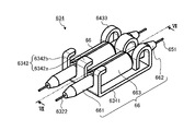
図2および図3に示すように、第1の伝送ケーブル6は、カメラヘッドコネクタ62内に設けられた第1の光電複合モジュール63と、ビデオコネクタ61内に設けられた第2の光電複合モジュール64と、第1の光電複合モジュール63と第2の光電複合モジュール64とを光学的および電気的に接続する複合ケーブル65と、第1の光電複合モジュール63と複合ケーブル65とを光学的に接続する第1の光コネクタ66と、第2の光電複合モジュール64と複合ケーブル65とを光学的に接続する第2の光コネクタ67と、第1の光電複合モジュール63、第2の光電複合モジュール64、複合ケーブル65、第1の光コネクタ66および第2の光コネクタ67を被覆する軟性の外被68(外郭)と、を備える。
As shown in FIGS. 2 and 3, the
〔第1の光電複合モジュールの構成〕
まず、第1の光電複合モジュール63について説明する。
第1の光電複合モジュール63は、内視鏡カメラヘッド5に設けられたハーメチックコネクタ50に機械的および電気的に接続する。第1の光電複合モジュール63は、内視鏡カメラヘッド5の撮像素子(図示せず)から出力された撮像信号(電気信号)を光信号に変換し、第1の光ファイバ6322および第1の光コネクタ66を介して複合ケーブル65(複数の第2の光ファイバ651)に出力する。また、第1の光電複合モジュール63は、第2の光電複合モジュール64および複合ケーブル65を介して制御装置9から出力された制御信号等(電気信号)を、内視鏡カメラヘッド5に設けられたハーメチックコネクタ50に中継する。第1の光電複合モジュール63は、レセプタクル631と、第1の基板632と、2つの第2の基板633と、保持部634と、第1の光コネクタ66と、を備える。
[Structure of the first photoelectric composite module]
First, the first photoelectric
The first photoelectric
レセプタクル631は、ハーメチックコネクタ50に機械的および電気的に接続する丸形コネクタで構成され、第1の光電複合モジュール63の先端に設けられている。レセプタクル631は、絶縁材料から構成されたインシュレータ6311と、複数のコンタクト6312と、を有する。インシュレータ6311は、ハーメチックコネクタ50にレセプタクル631が接続される際に、ハーメチックコネクタ50の複数の導通ピン501を挿入可能な複数の挿入孔6311aが形成されている。また、インシュレータ6311は、複数の挿入孔6311aの基端側それぞれに複数のコンタクト6312が設けられている。複数のコンタクト6312は、ハーメチックコネクタ50の複数の導通ピン501が複数の挿入孔6311aにそれぞれ挿入された際に、複数の導通ピン501と電気的に接続する。
The
第1の基板632は、リジッド基板で構成され、電気信号を光信号に変換するE/O変換部6321および第1の光コネクタ66を保持する保持部634(図2を参照)が実装されている。第1の基板632は、レセプタクル631の複数の第1のコンタクト6312aに電気的に接続し、内視鏡カメラヘッド5の撮像素子(図示せず)から出力され、複数の導通ピン501および複数の第1のコンタクト6312aを介して撮像信号(電気信号)をE/O変換部6321に中継する。E/O変換部6321には、複数の第1の光ファイバ6322が接続される。E/O変換部6321は、撮像信号(電気信号)を光信号に変換して複数の第1の光ファイバ6322に出力する。複数の第1の光ファイバ6322は、一端がE/O変換部6321に接続され、他端に第1の光コネクタ66の一部として機能する第1のフェルール661が設けられている。複数の第1の光ファイバ6322は、第1のフェルール661を介して複数の第2の光ファイバ651の一端に設けられた第2のフェルール662に光学的に接続される。保持部634は、割スリーブ663を用いて光学的に接続された複数の第1の光コネクタ66を保持する。なお、保持部634の詳細な構成は、後述する。
The
第2の基板633は、少なくとも一部が湾曲可能とするフレキシブル基板で構成され、複合ケーブル65に含まれる複数のメタルケーブル652と第2の基板633とを電気的および機械的に接続する第1のピンソケット6331(接続部)が実装されている。第2の基板633は、制御装置9から出力された制御信号等(電気信号)を、複数のメタルケーブル652およびコネクタ6521を介して複数の第2のコンタクト6312bに中継する。即ち、複数の第2のコンタクト6312bに中継された制御信号等(電気信号)は、複数の導通ピン501を介して内視鏡カメラヘッド5の撮像素子(図示せず)に出力される。これら2つの第2の基板633は、同一の構成を有する。また、2つの第2の基板633および第1の基板632は、一部が異なる平面にそれぞれ位置し、かつ、一部が互いに重なり合う状態で、立体的に配設されている。第1のピンソケット6331(メス型ソケット)は、半田等によって第2の基板633上に実装される。
The
第1の光コネクタ66は、複数の第1の光ファイバ6322および複数の第2の光ファイバ651の各々を光学的に接続する。第1の光コネクタ66は、第1の光ファイバ6322に設けられた第1のフェルール661と、第2の光ファイバ651の一端に設けられた第2のフェルール662と、第1のフェルール661と第2のフェルール662とを接続する割スリーブ663と、を有する。
The first
〔複合ケーブルの構成〕
次に、複合ケーブル65の構成について説明する。
複合ケーブル65は、光信号を伝送する複数の第2の光ファイバ651と、電気信号を伝送する複数のメタルケーブル652と、がユニット化されてなる。また、複合ケーブル65の両端の各々には、複合ケーブル65が折れ曲がることを防止するとともに、アースとして機能するGNDコネクタ69が設けられている。なお、GNDコネクタ69の詳細な構成は後述する。複数の第2の光ファイバ651は、一端に第1の光コネクタ66として機能する第2のフェルール662が設けられ、他端に第2の光コネクタ67として機能する第3のフェルール671が設けられている。また、複数のメタルケーブル652の各々は、両端に第1のピンソケット6331および第2のピンソケット6412に接続可能なコネクタ6521(オス型)が設けられている。
[Configuration of composite cable]
Next, the configuration of the
The
〔第2の光電複合モジュールの構成〕
次に、第2の光電複合モジュール64の構成について説明する。
第2の光電複合モジュール64は、制御装置9に設けられたレセプタクル(図示せず)に機械的、電気的および光学的に接続する。第2の光電複合モジュール64は、制御装置9から出力された制御信号等(電気信号)を複合ケーブル65(複数のメタルケーブル652)に中継する。また、第2の光電複合モジュール64は、複合ケーブル65を介して第1の光電複合モジュール63から出力された光信号を制御装置9へ中継する。第2の光電複合モジュール64は、第3の基板641と、第4の基板642と、コネクタプラグ643と、コリメータ部644と、第3の光ファイバ645と、第2の光コネクタ67と、を備える。
[Configuration of second optoelectronic composite module]
Next, the configuration of the second photoelectric
The second optoelectronic
第3の基板641は、外被68内に配設され、リジッド基板で構成される。第3の基板641は、第2の光コネクタ67を保持する保持部634(図2を参照)、複数のメタルケーブル652のコネクタ6521(オス型)と第3の基板641とを電気的および機械的に接続する第2のピンソケット6412(メス型ソケット)、および第4の基板642と電気的に接続するための基板間コネクタ6413が実装されている。第2のピンソケット6412および基板間コネクタ6413の各々は、半田等によって第3の基板641上に実装される。なお、保持部634の詳細な構成は、後述する。
A
第4の基板642は、外被68(被膜)内に配設され、リジット基板で構成される。第4の基板642は、コネクタプラグ643に設けられた複数のコネクタプラグ電極6431と第3の基板641とを中継する。また、第4の基板642は、複数の第3の光ファイバ645が挿入される挿入孔6422を有する。第4の基板642は、複数のコネクタプラグ電極6431(プラグ側電気接点)の各々と電気的に接続するとともに、基板間コネクタ6413を介して第3の基板641に電気的に接続する。
A
コリメータ部644は、第3の光ファイバ645が接続され、第3の光ファイバ645の出射端から出射された光(光信号)を平行光とする。
The
第2の光コネクタ67は、複数の第2の光ファイバ651および複数の第3の光ファイバ645の各々を光学的に接続する。第2の光コネクタ67は、第2の光ファイバ651に設けられた第3のフェルール671と、第3の光ファイバ645に設けられた第4のフェルール672と、第3のフェルール671と第4のフェルール672とを接続する割スリーブ673と、を有する。
The second
〔保持部の構成〕
次に、上述した保持部634の詳細な構成について説明する。
図4は、図2の保持部634を先端側(内視鏡カメラヘッド5側)から見た斜視図である。図5は、図2の保持部634を基端側から見た斜視図である。図6は、図2の保持部634のみの斜視図である。図7は、図4のVII-VII線断面図である。なお、図4~図7では、保持部634が第1の光コネクタ66を保持している状態について説明するが、第2の光コネクタ67を保持する場合であっても同様である。
[Configuration of holding part]
Next, a detailed configuration of the holding
FIG. 4 is a perspective view of the holding
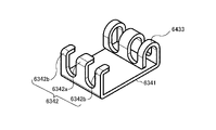
図4~図7に示すように、保持部634は、複数の第1の光コネクタ66または複数の第2の光コネクタ67を保持する。保持部634は、主面6341と、複数の鉤部6342と、複数のバネ部6433と、を有する。主面6341、複数の鉤部6342および複数のバネ部6433は、一体的に形成される。
As shown in FIGS. 4 to 7, the holding
複数の鉤部6342の各々は、主面6341の長手方向の端部から主面6341が載置された載置面と直交する方向に延在して主面6341側に向けて略直角に折り曲げられて形成される。複数の鉤部6342は、所定の間隔毎に設けられ、中央の鉤部6342aは、両端の鉤部6342bの幅より大きく形成される。具体的には、複数の鉤部6342は、第1のフェルール661の径と略同じ幅で形成され、かつ、割スリーブ663の径より小さい幅となるような間隔で設けられる。なお、図4~図7では、主面6341に対して3個の鉤部6342を設けた例を説明しているが、これに限定されることなく、保持する第1の光コネクタ66の数に応じて適宜変更することができる。
Each of the plurality of
複数のバネ部6433は、主面6341の長手方向の端部から主面6341が載置された載置面と直交する方向に延在して主面6341側に湾曲されて形成される。複数のバネ部6433は、第1の光コネクタ66が保持部634に収容された際に、第1の光コネクタ66を鉤部6342に向けて付勢する。
The plurality of
このように構成された保持部634は、まず、第1の光コネクタ66の先端側(第1のフェルール661)が鉤部6342に差し込まれた後、第1の光コネクタ66の後端側がバネ部6433に当接されながら押圧されることによって第1の光コネクタ66が収容される。これにより、保持部634は、バネ部6433が第1の光コネクタ66を鉤部6342に向けて付勢するので、第1の光コネクタ66が保持部634から外れることを防止することができる。
In the holding
〔GNDコネクタの構成〕
次に、上述した図2で説明したGNDコネクタ69の詳細な構成について説明する。
図8は、図2のGNDコネクタ69を先端側(内視鏡カメラヘッド5側)から見た斜視図である。図9は、図2のGNDコネクタ69の側面図である。図10は、図8のGNDコネクタ69を分割した状態の斜視図である。図11は、図9のGNDコネクタ69を分割した状態の側面図である。
[Configuration of GND connector]
Next, a detailed configuration of the
FIG. 8 is a perspective view of the
GNDコネクタ69は、複合ケーブル65の編組線65aを挟み込むことにより複合ケーブル65を保持する分割部692と、分割部692を結合する結合部693と、を有する。分割部692は、図10および図11に示すように分割可能であるとともに導電性の材質からなり、内部で複合ケーブル65の編組線65aを把持することにより、グランドとして機能させる編組線65aと同電位となる。なお、分割部692の端部には凸状の抜け防止部692aが設けられている。抜け防止部692aを複合ケーブル65の編組線65aと外被65bとの間に挿入させ、複合ケーブル65の外被65bが抜け防止部692aを覆う様に装着されることにより、複合ケーブル65が分割部692から抜けることを防止している。結合部693は、略円環状をなし、内部に複合ケーブル65の一部が挿通される。
The
このように構成されたGNDコネクタ69は、まず、複合ケーブル65の外被65bから露出した複合ケーブル65の編組線65aを、一対の分割部692によって挟み込み、複合ケーブル65の外被65bに覆われる様に一対の分割部692を複合ケーブル65に装着する。その後、一対の分割部692に結合部693をネジ6931によって固定する。これにより、GNDコネクタ69の前後に組み付ける部品、例えばフェルールや割スリーブの組み立て順序を考量することなく、固定することができる。
In the
〔第1の伝送ケーブルの製造方法〕
次に、上述した第1の伝送ケーブル6の製造方法について説明する。
図12A~図12Cは、第1の伝送ケーブル6の製造方法における要部を模式的に示す図である。
[Manufacturing method of the first transmission cable]
Next, a method for manufacturing the above-described
12A to 12C are diagrams schematically showing the main parts in the method of manufacturing the
図12Aに示すように、まず、作業者は、第1の光電複合モジュール63および第2の光電複合モジュール64の各々に対して、複合ケーブル65を接続する(図12A→図12B)。例えば、作業者は、第1の光電複合モジュール63の第1のフェルール661と、複合ケーブル65における第2の光ファイバ651の第2のフェルール662と、を割スリーブ663によって光学的に接続する。具体的には、作業者は、割スリーブ663内において第1のフェルール661の中心と、第2のフェルール662の中心とを突合わせる突合わせ工程を行う(第1の突き合わせ工程)。
As shown in FIG. 12A, the operator first connects the
続いて、作業者は、第1の光電複合モジュール63の第1のピンソケット6331に、メタルケーブル652のコネクタ6521を接続する(第1の接続工程)。
Subsequently, the operator connects the
その後、作業者は、第2の光電複合モジュール64と複合ケーブル65とを接続する。具体的には、作業者は、第2の光電複合モジュール64の第4のフェルール672と、複合ケーブル65の第3のフェルール671と、を割スリーブ673によって光学的に接続する。具体的には、作業者は、割スリーブ673内において第3のフェルール671の中心と、第4のフェルール672の中心とを突合わせる突合わせ工程を行う(第2の突き合わせ工程)。
After that, the operator connects the second photoelectric
続いて、作業者は、第2の光電複合モジュール64の第2のピンソケット6412に、メタルケーブル652のコネクタ6521を接続する(第2の接続工程)。
Subsequently, the operator connects the
その後、作業者は、第1の光コネクタ66および第2の光コネクタ67を保持部634によって収納し、この保持部634を第1の基板632および第3の基板641それぞれに配置させる(図12B→図12C)(保持工程)。
Thereafter, the operator accommodates the first
そして、作業者は、GNDコネクタ69を複合ケーブル65に接続し、外被68によって被覆する(被覆工程)。
Then, the operator connects the
以上説明した本実施の形態1によれば、光ファイバを用いた場合であっても、経済的に優れる。 According to the first embodiment described above, even when an optical fiber is used, it is economically superior.
また、本実施の形態1によれば、第1の光ファイバ6322、第2の光ファイバ651、第1の光ファイバ6322と第2の光ファイバ651とを接続する第1の光コネクタ66、第3の光ファイバ645、および、第2の光ファイバ651と第3の光ファイバ645とを接続する第2の光コネクタ67を第1の伝送ケーブル6内に内蔵させたので、E/O変換器またはO/E変換器との光軸合わせを容易に行うことができるうえ、E/O変換部6321に光ファイバを接続する際に、光ファイバが断線することを防止することができる。
Further, according to the first embodiment, the first
さらに、本実施の形態1によれば、光ファイバを変換器メーカ等に送付する必要がないので、経済的なコストを低減することができる。 Furthermore, according to the first embodiment, there is no need to send the optical fiber to the converter maker or the like, so the economic cost can be reduced.
また、本実施の形態1によれば、第1の光ファイバ6322、第2の光ファイバ651、第1の光ファイバ6322と第2の光ファイバ651とを接続する第1の光コネクタ66、第3の光ファイバ645、および、第2の光ファイバ651と第3の光ファイバ645とを接続する第2の光コネクタ67を第1の伝送ケーブル6内に内蔵させているため、例えば第2の光ファイバ651が断線した場合において、新たな第1の伝送ケーブル6に交換するとき、第1の光コネクタ66および第2の光コネクタ67を用いて各光ファイバを光学的に接続するので、容易に交換することができる。
Further, according to the first embodiment, the first
また、本実施の形態1によれば、電気信号を伝送する複数のメタルケーブル652と、第2の光ファイバ651とがユニット化されて複合ケーブル65として機能するので、第1の伝送ケーブル6の取り扱いを容易にすることができる。
Further, according to the first embodiment, the plurality of
また、本実施の形態1によれば、第2の基板633および第3の基板641に第1のピンソケット6331および第2のピンソケット6412の各々を設け、複数のメタルケーブル652の両端にコネクタ6521を設けてケーブルコネクタとして機能させることによって、メタルケーブル652の半田付けの工程を省略するとともに、容易に組み立てを行うことができる。
Further, according to the first embodiment, the
また、本実施の形態1によれば、第1の伝送ケーブル6の第1の光電複合モジュール63、第2の光電複合モジュール64および複合ケーブル65の各々をモジュール化することによって、E/O変換部6321と光ファイバとの接続工程およびコリメータ部644と光ファイバとの接続工程を順列に組み合わせる必要がなくなり、各接続工程を独立した工程とすることができるので、製造期間の短縮、仕損費の低減および最終組み立て加工の簡易化を行うことができる。
Further, according to the first embodiment, by modularizing each of the first photoelectric
なお、本実施の形態1では、複数のメタルケーブル652の両端にコネクタ6521を設け、第2の基板633に第1のピンソケット6331および第3の基板641に第2のピンソケット6412を設けることによって接続していたが、これに限定されることなく、図13に示す第1の伝送ケーブル6Aに示すように、複数のメタルケーブル652の各々の両端と第2の基板633および第3の基板641の各々を半田付けによって接続してもよい。
In the first embodiment, the
また、本実施の形態1では、制御装置9からの制御信号(電気信号)を複数のメタルケーブル652によって内視鏡カメラヘッド5へ伝送していたが、図14に示す第1の伝送ケーブル6Bに示すように、複数のメタルケーブル652に換えて、複数の光ファイバによって伝送するようにしてもよい。
Further, in
なお、本実施の形態1では、コリメータ部644を用いて制御装置9に光学的に接続していたが、例えば第3の基板641にO/E変換部を設け、光信号を電気信号に変換して制御装置9へ出力するようにしてもよい。この場合、O/E変換部に第3の光ファイバ645を設け、第2の光コネクタ67を用いて第2の光ファイバ651と光学的に接続させるとともに、基板間コネクタ6413を介してO/E変換部とコネクタプラグ643とを電気的に接続させるようにすればよい。
In the first embodiment, the
(実施の形態2)
次に、本発明の実施の形態2について説明する。上述した実施の形態1では、硬性内視鏡(挿入部2)を用いた医療用装置に本発明を適用していたが、本実施の形態2では、挿入部の先端側に撮像部を有する軟性内視鏡、所謂ビデオスコープを用いた医療用観察システムに本発明を適用する。なお、上述した実施の形態1と同様の構成には同一符号を付し、その詳細な説明は省略または簡略化する。
(Embodiment 2)
Next,
図15は、本実施の形態2に係る医療用装置の概略構成を示す図である。図15に示す医療用装置1Bは、生体内に挿入部2Aを挿入することによって被検体の観察部位の体内画像を撮像して画像信号を出力する内視鏡11と、内視鏡11の先端から出射する照明光を発生する光源装置3と、内視鏡11から出力された画像信号を処理して映像信号を生成して出力する制御装置9と、映像信号に基づく画像を表示する表示装置7と、を備える。
FIG. 15 is a diagram showing a schematic configuration of a medical device according to the second embodiment. A
内視鏡11は、図15に示すように、可撓性を有する細長形状をなす挿入部2Aと、挿入部2Aの基端側に接続され、各種の操作信号の入力を受け付ける操作部141と、操作部141から挿入部2Aが延びる方向と異なる方向に延び、光源装置3および制御装置9に接続し、上述した第1の伝送ケーブル6を含む各種ケーブルを内蔵するユニバーサルコード142と、を備える。
As shown in FIG. 15, the
挿入部2Aは、図15に示すように、生体内を撮像して画像信号を生成する撮像部(図示略)を内蔵した先端部22と、先端部22の基端側に接続され、複数の湾曲駒によって構成された湾曲自在な湾曲部23と、湾曲部23の基端側に接続され、可撓性を有する長尺状の可撓管部24と、を備える。そして、先端部22(撮像部)にて撮像された画像信号は、操作部141および上述した第1の伝送ケーブル6が内蔵されたユニバーサルコード142を介して、制御装置9に出力される。
As shown in FIG. 15, the
以上説明した本発明の実施の形態2によれば、軟性内視鏡(内視鏡11)を用いた場合であっても、上述した実施の形態1と同様の効果を奏する。 According to the second embodiment of the present invention described above, even when a flexible endoscope (endoscope 11) is used, the same effects as those of the first embodiment described above can be obtained.
(実施の形態3)
次に、本発明の実施の形態3について説明する。上述した実施の形態1では、硬性内視鏡(挿入部2)を用いた医療用装置1に本発明を適用していたが、本実施の形態3では、被検体内部(生体内)または被検体表面(生体表面)における所定の視野領域を拡大して撮像する手術用顕微鏡を用いた医療用装置に本発明を適用する。なお、以下の説明では、上述した実施の形態1と同様の構成には同一符号を付し、その詳細な説明は省略または簡略化する。
(Embodiment 3)
Next,
図16は、本実施の形態3に係る医療用装置の概略構成を示す図である。図16に示す医療用装置1Cは、被検体を撮像して画像信号を出力する手術用顕微鏡12と、手術用顕微鏡12から出力された画像信号を処理して映像信号を生成して出力する制御装置9と、映像信号に基づく画像を表示する表示装置7と、を備える。
FIG. 16 is a diagram showing a schematic configuration of a medical device according to the third embodiment. A
手術用顕微鏡12は、図16に示すように、被写体の微小部位を拡大して撮像し、画像信号を出力する顕微鏡部121と、顕微鏡部121の基端部に接続し、顕微鏡部121を回動可能に支持するアームを含む支持部122と、支持部122の基端部を回動可能に保持し、床面上を移動可能なベース部123と、を備える。
As shown in FIG. 16 , the
制御装置9は、図16に示すように、ベース部123に設置されている。また、支持部122には、支持部122に沿って第1の伝送ケーブル6が配線されている。すなわち、顕微鏡部121にて撮像された画像信号は、第1の伝送ケーブル6を介して、制御装置9に出力される。
The
なお、ベース部123は、床面上に移動可能に設けるのではなく、天井や壁面等に固定して支持部122を支持する構成としてもよい。また、ベース部123は、手術用顕微鏡12から被写体に照射する照明光を生成する光源部を備えていてもよい。
Note that the
以上説明した本発明の実施の形態3によれば、手術用顕微鏡12を用いた場合であっても、上述した実施の形態1と同様の効果を奏する。
According to the third embodiment of the present invention described above, even when the
なお、本発明の実施の形態3では、顕微鏡部121と制御装置9とを第1の伝送ケーブル6によって光学的および電気的に接続していたが、図17に示す医療用装置1Dのように、顕微鏡部121と制御装置9との間に中継器122Aを設け、顕微鏡部121と中継器122Aとを上述した第1の伝送ケーブル6と同様の構成を有する第1の伝送ケーブル6Aによって光学的および電気的に接続し、中継器122Aと制御装置9とを上述した第1の伝送ケーブル6と同様の構成を有する伝送ケーブル6Eによって光学的および電気的に接続してもよい。もちろん、顕微鏡部121と中継器122Aとを図14に示す光ファイバおよび光コネクタによって光学的に接続してもよい。
In
(その他の実施の形態)
本明細書における医療用装置の製造方法の説明では、「まず」、「その後」、「続いて」等の表現を用いて各工程の前後関係を明示していたが、本発明を実施するために必要な工程の順序は、それらの表現によって一意的に定められるわけではない。即ち、本明細書で記載した医療用装置の製造方法における工程の順序は、矛盾のない範囲で変更することができる。
(Other embodiments)
In the description of the manufacturing method of the medical device in this specification, expressions such as "first,""afterward," and "subsequently" are used to clearly indicate the relationship between steps. is not uniquely dictated by those representations. That is, the order of the steps in the methods of manufacturing the medical devices described herein may be changed within a consistent range.
このように、本発明は、ここでは記載していない様々な実施の形態を含みうるものであり、請求の範囲によって特定される技術的思想の範囲内で種々の設計変更等を行うことが可能である。 Thus, the present invention can include various embodiments not described here, and various design changes can be made within the scope of the technical ideas specified by the claims. is.
1,1B,1C,1D 医療用装置
2,2A 挿入部
3 光源装置
4 ライトガイド
5 内視鏡カメラヘッド
6,6A,6B 第1の伝送ケーブル
7 表示装置
8 第2の伝送ケーブル
9 制御装置
10 第3の伝送ケーブル
11 内視鏡
12 手術用顕微鏡
21 接眼部
22 先端部
23 湾曲部
24 可撓管部
50 ハーメチックコネクタ
61 ビデオコネクタ
62 カメラヘッドコネクタ
63 第1の光電複合モジュール
64 第2の光電複合モジュール
65 複合ケーブル
66 第1の光コネクタ
67 第2の光コネクタ
68 外被
69 GNDコネクタ
121 顕微鏡部
122 支持部
122A 中継器
123 ベース部
632 第1の基板
633 第2の基板
634 保持部
641 第3の基板
642 第4の基板
645 第3の光ファイバ
651 第2の光ファイバ
652 メタルケーブル
661 第1のフェルール
662 第2のフェルール
663,673 割スリーブ
671 第3のフェルール
672 第4のフェルール
692 分割部
693 結合部
6321 E/O変換部
6322 第1の光ファイバ
Claims (7)
前記カメラヘッドに接続されるカメラヘッドコネクタと、
前記画像処理装置に接続されるビデオコネクタと、
光信号を伝送する第1~第3の光ファイバと、
前記第1の光ファイバと前記第2の光ファイバとを接続する第1の光コネクタと、
前記第2の光ファイバと前記第3の光ファイバとを接続する第2の光コネクタと、
前記第1の光ファイバが接続され、電気信号を前記光信号に変換するE/O変換部と、
電気信号を伝送するメタルケーブルと前記第2の光ファイバと、がユニット化された複合ケーブルと、
を備え、
前記カメラヘッドコネクタは、
前記E/O変換部と、前記第1の光コネクタと、を配置する第1の基板と、
前記メタルケーブルから伝送された電気信号を前記カメラヘッドコネクタに伝送する第2の基板と、
を有し、
前記ビデオコネクタは、
前記第2の光コネクタを配置する第3の基板を有する伝送ケーブル。 A transmission cable for connecting a camera head to which a rigid endoscope is attachable and detachable and an image processing device for processing an imaging signal captured by the camera head,
a camera head connector connected to the camera head;
a video connector connected to the image processing device;
first to third optical fibers for transmitting optical signals;
a first optical connector that connects the first optical fiber and the second optical fiber;
a second optical connector that connects the second optical fiber and the third optical fiber;
an E/O converter to which the first optical fiber is connected and which converts an electrical signal into the optical signal;
a composite cable in which a metal cable for transmitting electrical signals and the second optical fiber are unitized;
with
The camera head connector is
a first substrate on which the E/O converter and the first optical connector are arranged;
a second substrate for transmitting electrical signals transmitted from the metal cable to the camera head connector;
has
The video connector is
A transmission cable having a third substrate on which the second optical connector is arranged.
立体的に配置される請求項1に記載の伝送ケーブル。 The first substrate and the second substrate are
2. The transmission cable according to claim 1, which is arranged three-dimensionally.
前記メタルケーブルの他端に設けられる第2のコネクタと、
前記第1のコネクタを接続する第1の接続部と、
前記第2のコネクタを接続する第2の接続部と、
をさらに備え、
前記第2の基板は、前記第1の接続部を配置され、
前記第3の基板は、
前記第2の光コネクタを配置する第1の面と、
前記第1の面とは反対側の面である第2の面と、
を有する請求項1または請求項2に記載の伝送ケーブル。 a first connector provided at one end of the metal cable;
a second connector provided at the other end of the metal cable;
a first connecting portion that connects the first connector;
a second connection portion that connects the second connector;
further comprising
The second substrate is arranged with the first connection portion,
The third substrate is
a first surface on which the second optical connector is arranged;
a second surface opposite to the first surface;
3. A transmission cable according to claim 1 or claim 2, comprising:
前記第2の光コネクタを保持する第2の保持部と、
をさらに備え、
前記第1の光コネクタは、
前記第1の保持部により、前記第1の基板に固定され、
前記第2の光コネクタは、
前記第2の保持部により、前記第3の基板に固定される、
請求項1~3のいずれか1つに記載の伝送ケーブル。 a first holding portion that holds the first optical connector;
a second holding portion that holds the second optical connector;
further comprising
The first optical connector is
fixed to the first substrate by the first holding part;
The second optical connector is
fixed to the third substrate by the second holding part;
The transmission cable according to any one of claims 1-3.
前記第1の光ファイバに設けられる第1のフェルールと、
前記第2の光ファイバに設けられる第2のフェルールと、
前記第1のフェルールと前記第2のフェルールとを接続するスリーブと、
を有する請求項1~4のいずれか1つに記載の伝送ケーブル。 The first optical connector is
a first ferrule provided on the first optical fiber;
a second ferrule provided on the second optical fiber;
a sleeve connecting the first ferrule and the second ferrule;
The transmission cable according to any one of claims 1 to 4, having
長方形をなす主面と、
前記主面の長手方向における一方の端部から、前記主面と直交する方向に延在して、前記主面側に向けて略直角に折り曲げられて形成される鉤部と、
前記主面の長手方向における他方の端部から、前記主面と直交する方向に延在して、前記主面側に湾曲し、前記第1の光コネクタを前記鉤部に向けて付勢する付勢部と、
を有する請求項4に記載の伝送ケーブル。 The first holding part is
a principal surface forming a rectangle;
a hook extending in a direction perpendicular to the principal surface from one end in the longitudinal direction of the principal surface and bent at a substantially right angle toward the principal surface;
Extending from the other end in the longitudinal direction of the main surface in a direction orthogonal to the main surface, curved toward the main surface, and biasing the first optical connector toward the hook. a biasing portion;
5. The transmission cable of claim 4, comprising:
Applications Claiming Priority (3)
| Application Number | Priority Date | Filing Date | Title |
|---|---|---|---|
| JP2017044213 | 2017-03-08 | ||
| JP2017044213 | 2017-03-08 | ||
| JP2019504310A JPWO2018163498A1 (en) | 2017-03-08 | 2017-10-25 | Medical device and method of manufacturing medical device |
Related Parent Applications (1)
| Application Number | Title | Priority Date | Filing Date |
|---|---|---|---|
| JP2019504310A Division JPWO2018163498A1 (en) | 2017-03-08 | 2017-10-25 | Medical device and method of manufacturing medical device |
Publications (2)
| Publication Number | Publication Date |
|---|---|
| JP2021193446A JP2021193446A (en) | 2021-12-23 |
| JP7143492B2 true JP7143492B2 (en) | 2022-09-28 |
Family
ID=63447477
Family Applications (2)
| Application Number | Title | Priority Date | Filing Date |
|---|---|---|---|
| JP2019504310A Ceased JPWO2018163498A1 (en) | 2017-03-08 | 2017-10-25 | Medical device and method of manufacturing medical device |
| JP2021124521A Active JP7143492B2 (en) | 2017-03-08 | 2021-07-29 | transmission cable |
Family Applications Before (1)
| Application Number | Title | Priority Date | Filing Date |
|---|---|---|---|
| JP2019504310A Ceased JPWO2018163498A1 (en) | 2017-03-08 | 2017-10-25 | Medical device and method of manufacturing medical device |
Country Status (5)
| Country | Link |
|---|---|
| US (2) | US11166621B2 (en) |
| EP (1) | EP3586714B1 (en) |
| JP (2) | JPWO2018163498A1 (en) |
| CN (1) | CN110381796B (en) |
| WO (1) | WO2018163498A1 (en) |
Families Citing this family (2)
| Publication number | Priority date | Publication date | Assignee | Title |
|---|---|---|---|---|
| WO2020179067A1 (en) * | 2019-03-07 | 2020-09-10 | オリンパス株式会社 | Endoscope optical transducer, endoscope imaging device, and endoscope |
| CN116115154A (en) * | 2021-12-30 | 2023-05-16 | 武汉迈瑞医疗技术研究院有限公司 | Endoscope image pickup device, communication cable, and endoscope image pickup apparatus |
Citations (6)
| Publication number | Priority date | Publication date | Assignee | Title |
|---|---|---|---|---|
| JP2009273652A (en) | 2008-05-14 | 2009-11-26 | Olympus Corp | Endoscope system and connector cover |
| JP2010096838A (en) | 2008-10-14 | 2010-04-30 | Advanced Cable Systems Corp | Optical connector |
| JP2014076097A (en) | 2012-10-09 | 2014-05-01 | Fujifilm Corp | Connection structure between optical fibers and endoscope system |
| JP2015134039A (en) | 2014-01-16 | 2015-07-27 | ソニー・オリンパスメディカルソリューションズ株式会社 | Photoelectric composite module, camera head, and endoscope device |
| CN204631296U (en) | 2015-02-12 | 2015-09-09 | 嘉基电子科技(苏州)有限公司 | Light coupling assembling |
| JP2016209541A (en) | 2015-04-30 | 2016-12-15 | ソニー・オリンパスメディカルソリューションズ株式会社 | Medical observation apparatus |
Family Cites Families (44)
| Publication number | Priority date | Publication date | Assignee | Title |
|---|---|---|---|---|
| US4416268A (en) * | 1980-07-10 | 1983-11-22 | Olympus Optical Co., Ltd. | Endoscope having two detachable armour tubes |
| JP3715718B2 (en) * | 1996-07-17 | 2005-11-16 | キヤノン株式会社 | Imaging device |
| JPH1033473A (en) * | 1996-07-19 | 1998-02-10 | Olympus Optical Co Ltd | Endoscope device |
| JP4061682B2 (en) * | 1996-12-27 | 2008-03-19 | 住友電気工業株式会社 | Method for forming optical connector ferrule |
| JPH10314113A (en) * | 1997-05-15 | 1998-12-02 | Fuji Photo Optical Co Ltd | Electric connector for electronic endoscope |
| JP2000147392A (en) * | 1998-11-18 | 2000-05-26 | Nippon Sheet Glass Co Ltd | Objective lens for endoscope |
| JP2003195111A (en) * | 2001-10-17 | 2003-07-09 | Fujitsu Component Ltd | Plastic ferrule, and its manufacturing method and mold |
| JP2003338805A (en) * | 2002-03-15 | 2003-11-28 | Kddi Submarine Cable Systems Inc | Optical transmission system, optical transmitter and methods thereof |
| JP3803073B2 (en) * | 2002-06-28 | 2006-08-02 | 矢崎総業株式会社 | Optical connector |
| JP2004202040A (en) | 2002-12-26 | 2004-07-22 | I Systems:Kk | Electronic endoscopic apparatus |
| JP2005181902A (en) * | 2003-12-22 | 2005-07-07 | Kyocera Corp | Optical connector |
| US7712976B2 (en) * | 2006-04-10 | 2010-05-11 | Finisar Corporation | Active optical cable with integrated retiming |
| WO2010051401A1 (en) * | 2008-10-31 | 2010-05-06 | Vascular Imaging Corporation | Optical imaging probe connector |
| JP5258613B2 (en) * | 2009-02-16 | 2013-08-07 | 富士フイルム株式会社 | Light guide, light source device and endoscope system |
| JP5475342B2 (en) * | 2009-06-25 | 2014-04-16 | 富士フイルム株式会社 | Endoscope system |
| JP5192452B2 (en) * | 2009-06-25 | 2013-05-08 | 富士フイルム株式会社 | Optical fiber connection structure and endoscope system |
| JP5448885B2 (en) * | 2010-01-28 | 2014-03-19 | 富士フイルム株式会社 | Medical equipment and endoscope device |
| CN102948141B (en) * | 2010-05-28 | 2016-08-10 | 索尼公司 | Image capture apparatus and image-capturing method |
| JP5417268B2 (en) * | 2010-06-28 | 2014-02-12 | 富士フイルム株式会社 | Endoscope system |
| CN103081456A (en) | 2010-09-10 | 2013-05-01 | 奥林巴斯医疗株式会社 | Image capture device |
| DE102011106386A1 (en) * | 2011-07-04 | 2013-01-10 | Karl Storz Gmbh & Co. Kg | Endoscopic arrangement |
| JP5868629B2 (en) | 2011-08-02 | 2016-02-24 | オリンパス株式会社 | Light source device |
| US8985867B2 (en) * | 2011-09-07 | 2015-03-24 | Adc Telecommunications, Inc. | Optical fiber connection system |
| US8942530B2 (en) | 2011-09-20 | 2015-01-27 | San Marino Capital, Inc. | Endoscope connector method and apparatus |
| CN104011572B (en) * | 2011-11-23 | 2016-03-16 | Adc电信公司 | The joints of optical fibre of many optical fiber |
| US9033592B2 (en) * | 2012-04-13 | 2015-05-19 | Sumitomo Electric Industries, Ltd. | Optical connector module |
| WO2014006536A2 (en) * | 2012-07-02 | 2014-01-09 | Koninklijke Philips N.V. | Minimally invasive medical instrument |
| CN102868447B (en) * | 2012-09-24 | 2015-07-15 | 深圳太辰光通信股份有限公司 | Fiber grating tracker and fault detection method of optical fiber circuit |
| CN103091795B (en) * | 2013-01-28 | 2015-04-22 | 深圳市特发信息光网科技股份有限公司 | Machinery type field-assembled optical fiber connector |
| EP2987449A4 (en) * | 2013-04-19 | 2017-01-04 | Olympus Corporation | Image capture device and processing device |
| JP6389383B2 (en) * | 2014-06-27 | 2018-09-12 | ソニー・オリンパスメディカルソリューションズ株式会社 | Optical connector and medical device |
| JP6556430B2 (en) * | 2014-06-27 | 2019-08-07 | ソニー・オリンパスメディカルソリューションズ株式会社 | Medical equipment |
| JP5869194B1 (en) * | 2014-07-02 | 2016-02-24 | オリンパス株式会社 | Imaging apparatus, endoscope system, and endoscope apparatus |
| US9651745B2 (en) * | 2014-09-25 | 2017-05-16 | Optomedia Technology Inc | Optical connector module for aligning optical connectors to optical connecting seat |
| JP6498903B2 (en) * | 2014-09-30 | 2019-04-10 | 富士通コンポーネント株式会社 | Clip for ferrule, optical module and optical connector |
| JP6076554B2 (en) | 2014-12-15 | 2017-02-08 | オリンパス株式会社 | A set of connectors, a flange, a method of manufacturing a set of connectors, and an endoscope |
| US10578854B2 (en) | 2015-03-17 | 2020-03-03 | Sony Corporation | Optical connector, optical connector set, image pickup unit, image pickup system, and optical transmission module |
| JP6177463B2 (en) * | 2015-04-23 | 2017-08-09 | オリンパス株式会社 | Endoscope system |
| US10405733B2 (en) * | 2015-04-30 | 2019-09-10 | Sony Olympus Medical Solutions Inc. | Medical signal processing device and medical observation system |
| CN104991313A (en) * | 2015-06-28 | 2015-10-21 | 中航光电科技股份有限公司 | Tensile structure of optical fiber connector |
| JP2017134282A (en) * | 2016-01-28 | 2017-08-03 | ソニー株式会社 | Optical connector and optical transmission module |
| JP2017138535A (en) * | 2016-02-05 | 2017-08-10 | 富士通コンポーネント株式会社 | Ferrule connection component |
| JP7039548B2 (en) * | 2016-07-14 | 2022-03-22 | インテュイティブ サージカル オペレーションズ, インコーポレイテッド | Pressure test port housed inside the body of the surgical instrument |
| WO2018157115A1 (en) * | 2017-02-27 | 2018-08-30 | Commscope, Inc. Of North Carolina | Hardened converter and sealing shell for field terminated connector |
-
2017
- 2017-10-25 EP EP17900201.9A patent/EP3586714B1/en active Active
- 2017-10-25 CN CN201780087358.4A patent/CN110381796B/en active Active
- 2017-10-25 US US16/490,079 patent/US11166621B2/en active Active
- 2017-10-25 WO PCT/JP2017/038576 patent/WO2018163498A1/en unknown
- 2017-10-25 JP JP2019504310A patent/JPWO2018163498A1/en not_active Ceased
-
2021
- 2021-07-29 JP JP2021124521A patent/JP7143492B2/en active Active
- 2021-10-04 US US17/492,676 patent/US20220022729A1/en active Pending
Patent Citations (6)
| Publication number | Priority date | Publication date | Assignee | Title |
|---|---|---|---|---|
| JP2009273652A (en) | 2008-05-14 | 2009-11-26 | Olympus Corp | Endoscope system and connector cover |
| JP2010096838A (en) | 2008-10-14 | 2010-04-30 | Advanced Cable Systems Corp | Optical connector |
| JP2014076097A (en) | 2012-10-09 | 2014-05-01 | Fujifilm Corp | Connection structure between optical fibers and endoscope system |
| JP2015134039A (en) | 2014-01-16 | 2015-07-27 | ソニー・オリンパスメディカルソリューションズ株式会社 | Photoelectric composite module, camera head, and endoscope device |
| CN204631296U (en) | 2015-02-12 | 2015-09-09 | 嘉基电子科技(苏州)有限公司 | Light coupling assembling |
| JP2016209541A (en) | 2015-04-30 | 2016-12-15 | ソニー・オリンパスメディカルソリューションズ株式会社 | Medical observation apparatus |
Also Published As
| Publication number | Publication date |
|---|---|
| EP3586714A1 (en) | 2020-01-01 |
| CN110381796B (en) | 2022-04-22 |
| CN110381796A (en) | 2019-10-25 |
| JP2021193446A (en) | 2021-12-23 |
| EP3586714A4 (en) | 2020-03-04 |
| JPWO2018163498A1 (en) | 2020-05-14 |
| US20220022729A1 (en) | 2022-01-27 |
| US11166621B2 (en) | 2021-11-09 |
| US20200029790A1 (en) | 2020-01-30 |
| WO2018163498A1 (en) | 2018-09-13 |
| EP3586714B1 (en) | 2024-03-20 |
Similar Documents
| Publication | Publication Date | Title |
|---|---|---|
| JP7143492B2 (en) | transmission cable | |
| US9261662B2 (en) | Photoelectric conversion connector, optical transmission module, imaging apparatus, and endoscope | |
| US9125553B2 (en) | Endoscope with electrical conductive portion | |
| US11737652B2 (en) | Medical device assembly and related methods | |
| US20130158350A1 (en) | Electrical connecting element and endoscopy system | |
| WO2017013745A1 (en) | Cable connection structure, endoscope system, and method for manufacturing cable connection structure | |
| US10687696B2 (en) | Endoscope system with communication mode stabilizing unit | |
| EP3195792A1 (en) | Optical transmitter unit, method for connecting optical transmitter module and transmission-side optical connector, and endoscope system | |
| WO2018230368A1 (en) | Image capture unit and endoscope | |
| WO2021181620A1 (en) | Endoscope processor and endoscope system | |
| WO2016047172A1 (en) | Optical transmitter/receiver unit | |
| JP2018092844A (en) | Medical treatment coaxial connector, medical treatment coaxial cable, and medical treatment observation system | |
| JP5851661B1 (en) | Optical transceiver unit | |
| WO2021181914A1 (en) | Medical observation system and transmission cable | |
| US20220296089A1 (en) | Endoscope, distal end portion of endoscope, and insertion portion of endoscope | |
| WO2020188723A1 (en) | Holding frame, endoscope distal end structure, and endoscope |
Legal Events
| Date | Code | Title | Description |
|---|---|---|---|
| A621 | Written request for application examination |
Free format text: JAPANESE INTERMEDIATE CODE: A621 Effective date: 20210729 |
|
| A977 | Report on retrieval |
Free format text: JAPANESE INTERMEDIATE CODE: A971007 Effective date: 20220617 |
|
| A131 | Notification of reasons for refusal |
Free format text: JAPANESE INTERMEDIATE CODE: A131 Effective date: 20220705 |
|
| A521 | Request for written amendment filed |
Free format text: JAPANESE INTERMEDIATE CODE: A523 Effective date: 20220804 |
|
| TRDD | Decision of grant or rejection written | ||
| A01 | Written decision to grant a patent or to grant a registration (utility model) |
Free format text: JAPANESE INTERMEDIATE CODE: A01 Effective date: 20220823 |
|
| A61 | First payment of annual fees (during grant procedure) |
Free format text: JAPANESE INTERMEDIATE CODE: A61 Effective date: 20220914 |
|
| R151 | Written notification of patent or utility model registration |
Ref document number: 7143492 Country of ref document: JP Free format text: JAPANESE INTERMEDIATE CODE: R151 |