EP3286999B1 - Coupe-rubans - Google Patents
Coupe-rubans Download PDFInfo
- Publication number
- EP3286999B1 EP3286999B1 EP17160515.7A EP17160515A EP3286999B1 EP 3286999 B1 EP3286999 B1 EP 3286999B1 EP 17160515 A EP17160515 A EP 17160515A EP 3286999 B1 EP3286999 B1 EP 3286999B1
- Authority
- EP
- European Patent Office
- Prior art keywords
- belt
- hand side
- speed
- speeds
- central
- Prior art date
- Legal status (The legal status is an assumption and is not a legal conclusion. Google has not performed a legal analysis and makes no representation as to the accuracy of the status listed.)
- Active
Links
- 239000000463 material Substances 0.000 description 7
- 238000005259 measurement Methods 0.000 description 6
- 244000188595 Brassica sinapistrum Species 0.000 description 5
- 235000004977 Brassica sinapistrum Nutrition 0.000 description 5
- 230000000903 blocking effect Effects 0.000 description 4
- 238000003306 harvesting Methods 0.000 description 4
- 238000009825 accumulation Methods 0.000 description 3
- 230000008901 benefit Effects 0.000 description 3
- 230000008859 change Effects 0.000 description 3
- 230000001276 controlling effect Effects 0.000 description 3
- 230000002441 reversible effect Effects 0.000 description 3
- 235000013339 cereals Nutrition 0.000 description 2
- 230000001419 dependent effect Effects 0.000 description 2
- 238000007726 management method Methods 0.000 description 2
- 230000001737 promoting effect Effects 0.000 description 2
- 241000209140 Triticum Species 0.000 description 1
- 235000021307 Triticum Nutrition 0.000 description 1
- 230000001133 acceleration Effects 0.000 description 1
- 230000009471 action Effects 0.000 description 1
- 238000002485 combustion reaction Methods 0.000 description 1
- 230000008878 coupling Effects 0.000 description 1
- 238000010168 coupling process Methods 0.000 description 1
- 238000005859 coupling reaction Methods 0.000 description 1
- 230000000694 effects Effects 0.000 description 1
- 238000005265 energy consumption Methods 0.000 description 1
- 230000007613 environmental effect Effects 0.000 description 1
- 230000007246 mechanism Effects 0.000 description 1
- 230000007935 neutral effect Effects 0.000 description 1
- 230000009467 reduction Effects 0.000 description 1
- 230000001105 regulatory effect Effects 0.000 description 1
- 239000010902 straw Substances 0.000 description 1
- 230000032258 transport Effects 0.000 description 1
- 238000004804 winding Methods 0.000 description 1
Images

Classifications
-
- A—HUMAN NECESSITIES
- A01—AGRICULTURE; FORESTRY; ANIMAL HUSBANDRY; HUNTING; TRAPPING; FISHING
- A01D—HARVESTING; MOWING
- A01D41/00—Combines, i.e. harvesters or mowers combined with threshing devices
- A01D41/12—Details of combines
- A01D41/127—Control or measuring arrangements specially adapted for combines
-
- A—HUMAN NECESSITIES
- A01—AGRICULTURE; FORESTRY; ANIMAL HUSBANDRY; HUNTING; TRAPPING; FISHING
- A01D—HARVESTING; MOWING
- A01D57/00—Delivering mechanisms for harvesters or mowers
- A01D57/20—Delivering mechanisms for harvesters or mowers with conveyor belts
-
- A—HUMAN NECESSITIES
- A01—AGRICULTURE; FORESTRY; ANIMAL HUSBANDRY; HUNTING; TRAPPING; FISHING
- A01D—HARVESTING; MOWING
- A01D41/00—Combines, i.e. harvesters or mowers combined with threshing devices
- A01D41/12—Details of combines
- A01D41/14—Mowing tables
- A01D41/141—Automatic header control
-
- A—HUMAN NECESSITIES
- A01—AGRICULTURE; FORESTRY; ANIMAL HUSBANDRY; HUNTING; TRAPPING; FISHING
- A01D—HARVESTING; MOWING
- A01D61/00—Elevators or conveyors for binders or combines
- A01D61/002—Elevators or conveyors for binders or combines transversal conveying devices
-
- A—HUMAN NECESSITIES
- A01—AGRICULTURE; FORESTRY; ANIMAL HUSBANDRY; HUNTING; TRAPPING; FISHING
- A01D—HARVESTING; MOWING
- A01D61/00—Elevators or conveyors for binders or combines
- A01D61/008—Elevators or conveyors for binders or combines for longitudinal conveying, especially for combines
-
- A—HUMAN NECESSITIES
- A01—AGRICULTURE; FORESTRY; ANIMAL HUSBANDRY; HUNTING; TRAPPING; FISHING
- A01D—HARVESTING; MOWING
- A01D61/00—Elevators or conveyors for binders or combines
- A01D61/02—Endless belts
-
- A—HUMAN NECESSITIES
- A01—AGRICULTURE; FORESTRY; ANIMAL HUSBANDRY; HUNTING; TRAPPING; FISHING
- A01D—HARVESTING; MOWING
- A01D75/00—Accessories for harvesters or mowers
- A01D75/28—Control mechanisms for harvesters or mowers when moving on slopes; Devices preventing lateral pull
- A01D75/287—Control mechanisms for harvesters or mowers when moving on slopes; Devices preventing lateral pull acting on the mowing table
-
- B—PERFORMING OPERATIONS; TRANSPORTING
- B65—CONVEYING; PACKING; STORING; HANDLING THIN OR FILAMENTARY MATERIAL
- B65G—TRANSPORT OR STORAGE DEVICES, e.g. CONVEYORS FOR LOADING OR TIPPING, SHOP CONVEYOR SYSTEMS OR PNEUMATIC TUBE CONVEYORS
- B65G43/00—Control devices, e.g. for safety, warning or fault-correcting
-
- A—HUMAN NECESSITIES
- A01—AGRICULTURE; FORESTRY; ANIMAL HUSBANDRY; HUNTING; TRAPPING; FISHING
- A01D—HARVESTING; MOWING
- A01D41/00—Combines, i.e. harvesters or mowers combined with threshing devices
- A01D41/02—Self-propelled combines
-
- B—PERFORMING OPERATIONS; TRANSPORTING
- B65—CONVEYING; PACKING; STORING; HANDLING THIN OR FILAMENTARY MATERIAL
- B65G—TRANSPORT OR STORAGE DEVICES, e.g. CONVEYORS FOR LOADING OR TIPPING, SHOP CONVEYOR SYSTEMS OR PNEUMATIC TUBE CONVEYORS
- B65G2203/00—Indexing code relating to control or detection of the articles or the load carriers during conveying
- B65G2203/02—Control or detection
- B65G2203/0266—Control or detection relating to the load carrier(s)
- B65G2203/0291—Speed of the load carrier
Definitions
- the present invention relates to a combine harvester with a band cutting device according to the preamble of claim 1.
- Attachments for harvesting machines have a conveying device behind the cutter bars in order to feed the cut crop over the entire width of the attachment to a feed channel, which is often arranged in the center, of an inclined conveyor.
- feed screws that is to say rolls with counter-rotating screw turns and / or conveyor belts, are used as conveying devices.
- Attachments whose crop is conveyed to the feed channel essentially by means of conveyor belts are called belt cutting units.
- the conveyor belts of the belt cutting units convey the crop more gently and evenly to the feed channel than feed augers, especially even with small amounts of crop.
- Belt cutting units also generally have a lower weight, which means that large cutting unit widths are possible. They also enable higher crop throughput.
- the object of the invention is to create the existing disadvantages of the prior art and in particular a self-propelled combine harvester with a belt cutting device and an alternative control of the belt speed of the conveyor belts, which improves the crop throughput.
- a combine harvester with a belt cutting unit which comprises at least one center belt for conveying crop to a feed roller and / or to a feed channel of an inclined conveyor, and at least one cross conveyor belt arranged on the left side and one on the right side to the center belt for conveying the crop to the center belt and the center belt
- the left-hand and right-hand cross conveyor belts are arranged behind a cutter bar in the direction of travel
- the center belt, the left-hand and right-hand cross conveyor belts can each be operated at an individual belt speed
- the combine harvester and / or the belt cutting device has a control unit, and the control unit is set up for this purpose, the belt speeds of the left-hand and right-hand cross conveyor belts in each case as a function of a right-of-way speed, and the belt speed of the center belt as a function of the right-of-way speed or as a function of the belt
- Automatically controlling the speed of the left-hand and right-hand cross conveyor belts ensures that the throughput is improved by the convey
- the right-of-way speed is directly related to the amount of crop to be picked up by the belt cutting unit per unit of time.
- the belt speeds can thus be automatically adapted to the crop quantities per unit of time as a result of the automatic control of the belt speeds as a function of the forward speed, whereby the crop throughput is optimized and evened out. Furthermore, the risk of overloading the center belt and / or the cross conveyor belts due to too much crop is reduced.
- the belt speed of the center belt can be set differently to the belt speeds of the cross conveyor belts. The belt speed of the center belt can thus be easily adapted to the additional loading of crop material by the cross conveyor belts.
- the belt speeds of the left-hand and right-hand cross conveyor belts and / or the belt speed of the center belt is coupled to the right of way.
- the control unit can easily control the belt speeds as a function of the quantity of crop.
- the belt speed of the center belt is coupled to the belt speeds of at least the left-hand and / or the right-hand cross conveyor belt.
- the belt speed of the center belt can be easily adapted to the belt speed of the cross conveyor belts.
- the belt speed of the center belt can thus be adapted to the crop flow from the cross conveyor belts.
- An optimal ratio of the belt speeds to each other can be set.
- the optimal ratio of the belt speeds to each other can be maintained when changing the right of way.
- the belt speed of the center belt, the belt speed of the left-hand cross conveyor belt and / or the belt speed of the right-hand cross conveyor belt are coupled to the forward speed specific to the crop, in particular in such a way that higher belt speeds are set for cereals and lower belt speeds for rapeseed become.
- this has the effect that, in the case of crops with a low density, such as rapeseed, slippage between the crop and the center belt and the cross conveyor belts is prevented or reduced and the crop is reliably caught by the center belt and the cross conveyor belts.
- a minimum belt speed and a maximum belt speed can be set for the center belt, the left-hand and the right-hand cross conveyor belt.
- the minimum belt speed prevents the center belt and cross conveyor belts from stopping at slow forward speeds.
- the maximum belt speed prevents the slippage between the crop and the central belt and the cross conveyor belts from becoming too large. This means that the crop is captured and conveyed more reliably by the center belt and the cross conveyor belts.
- the center belt preferably has a higher belt speed than the left-hand and the right-hand cross conveyor belt.
- the belt speeds of the left-hand and right-hand cross conveyor belts are controlled as a function of the slope of the belt cutting device and the conveying directions of the left-hand and right-hand cross conveyor belts, in particular the belt speed of the uphill-conveying cross conveyor belt is increased and / or the belt speed of the downhill cross conveyor is reduced. This can compensate for the downward movement of the crop due to the incline and the crop can be conveyed evenly on slopes.
- the belt speed of the center belt can be regulated as a function of the slope of the belt cutter.
- the left-hand and the right-hand cross conveyor belt By lowering the belt speeds of the center belt, the left-hand and the right-hand cross conveyor belt to the minimum belt speed when moving out of a crop stock, in an advantageous embodiment of the invention it is ensured that the wear of the center belt and the cross conveyor belts is kept low. It also reduces energy consumption.
- the belt speeds of the left-hand and right-hand cross conveyor belts and the belt speed of the center belt can be adjusted manually in a range between the minimum belt speed and the maximum belt speed. This enables the vehicle driver to set the required belt speeds himself if, among other things, the crop condition, e.g. the crop moisture or the crop density makes this necessary.
- the vehicle driver can preferably switch between an automatic mode, in which the control unit controls, and a manual mode.
- the inclined conveyor has a chain conveyor, and a direction of rotation of the feed roller and / or a conveying direction of the chain conveyor of the inclined conveyor and the conveying direction of the center belt are mutually reversible, and the left-hand and right-hand transverse conveyor belts can be stopped.
- the chain conveyor of the inclined conveyor is blocked or overloaded with too much crop, or when the feed channel is blocked by accumulated crop, the crop can be reversed.
- the crop that is conveyed out of the inclined conveyor in the direction of travel is conveyed back to the center belt by the feed roller, which conveys the crop in the direction of travel FR and in front of the belt cutting unit.
- the center band is preferably decelerated and accelerated slowly. This gentle start-up has the particular advantage that the slip between the crop and the center belt is kept to a minimum. As a result, the crop is captured better and conveyed faster in the opposite direction.
- the combine harvester has a multifunction handle with a switch in a driver's cab, the switch reversing the center belt, the left-hand and the right-hand cross conveyor belt in a first switching position and the belt speeds of the center belt, the left-hand and of the right-hand cross conveyor belt to a fixed value, in particular to 25% of the set belt speeds.
- This configuration has the advantage that the driver has direct and quick access to the most important functions. Reversing, i.e. reversing the conveying directions, serves to release blockages in the center belt and / or the transverse conveyor belts.
- the driver can react to local low stock densities in order to even out a crop flow.
- the belt cutter behind the center belt has a feed roller for pulling the crop into the feed channel and / or has at least one guide screw for conveying crop to the feed roller and / or the center belt, and the control unit is set up to set a speed of rotation of the feed roller and / or to control a speed of the guide auger depending on the right of way, it is ensured that the crop is transferred to the feeder of the combine without any problems.
- the speeds can be automatically adapted to the crop quantities in a simple manner, as a result of which the crop throughput is increased and / or equalized.
- the guide screw is particularly advantageous for bulky crops such as rapeseed.
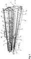
- Figure 1 shows a schematic perspective view of a combine harvester 1 with a band cutting device 2.
- the belt cutting unit 2 is arranged on a inclined conveyor 3 of the combine harvester 1 on the front side of the combine harvester 1, in particular mounted.
- the band cutting device 2 has a longitudinal axis 4 which extends in the center and parallel to a direction of travel FR.
- the band cutting device 2 has a frame 5.
- the belt cutter 2 has a center belt 6 and a cross conveyor belt 7, 8, which is arranged on the left-hand side and a right-hand side of the center belt 6.
- the center belt 6 and the cross conveyor belts 7, 8 are arranged such that they together extend essentially over an entire width 9 of the belt cutting unit 2.
- the center belt 6 and the cross conveyor belts 7, 8 each comprise an endless belt 10.
- a continuous, preferably flexible, cutter bar 11 is arranged. Furthermore, a pivotable reel 12 is arranged on the frame 5 of the band cutting unit 2. The cutter bar 11 and the reel 12 extend essentially over the width 9 of the belt cutting unit 2.
- a feed roller 13 with finger elements 14 is arranged on the upper side and essentially over a width of the center belt 6.
- the feed roller 13 can also be designed, for example, as a feed screw with screw turns.
- a feed channel 19 of the inclined conveyor 3 of the combine harvester 1 is arranged behind the feed roller 13.
- a guide screw 15 extends above the center belt 6, the cross conveyor belts 7, 8 and the feed roller 13 and essentially over the width 9 of the belt cutting device 2 transversely to the direction of travel FR.
- the guide screw 15 has two rolls 16, 17 with opposing screw turns 18.
- Combine 1 also has an in Fig. 1 only schematically indicated control unit 20 for controlling, among other things, the band cutting unit 2, which will be described later.
- the control unit 20 controls the cutter bar 11, the feed roller 13, the guide screw 15 and in particular the center belt 6 and the transverse conveyor belts 7, 8 of the belt cutting unit 2.
- the control unit 20 can alternatively be integrated in a central control and control unit in the combine harvester 1.
- the control unit 20 can also be assigned to the band cutting unit 2 or the control system can be divided between several control units 20.
- the combine harvester 1 has a driver's cab 21 on the front.
- the center belt 6 is arranged below the cross conveyor belts 7, 8, so that harvested crop falls onto the center belt 6 when it is conveyed from the cross conveyor belts 7, 8.
- the center belt 6 conveys the crop to the feed roller 13. This captures the crop, compresses it and transports it into the feed channel 19 of the inclined conveyor 3.
- the crop is then conveyed by the inclined conveyor 3 to the threshing unit (not shown) of the combine harvester 1, where it continues is processed.
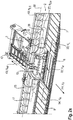
- a common hydraulic pump is assigned to both hydraulic motors 47, 48 of the cross conveyor belts 7, 8. This is particularly advantageous in an embodiment in which both transverse conveyor belts 7, 8 are driven with identical belt speeds v L , v R.
- the hydraulic pumps 49-51 are driven by a gear 52 of the band cutting unit 2.
- the feed roller 13 is preferably mechanically driven via the gear 52 of the band cutting unit 2 and controlled at the speed 36.
- the chain conveyor 42 of the inclined conveyor 3 is preferably mechanically driven by means of V-belts and controlled by means of a variator (not shown).
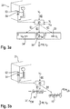
- Figure 3a shows the control according to the invention of the center belt 6 and the cross conveyor belts 7, 8 and a multifunction handle 53 in the driver's cab 21.
- the control unit 20 controls the belt speeds v M , v L , v R of the center belt 6 and the left-hand and right-hand cross-conveyor belt 7 , 8 automatically as a function of the right of way speed v F in such a way that the belt speeds v M , v L , v R of the center belt 6 and the cross conveyor belts 7, 8 are adapted to the right of way speed v F.
- the belt speeds v L , v R of the cross conveyor belts 7,8 are adapted to the forward speed v F and the belt speed v M of the center belt 6 to the belt speeds v L , v R of the cross conveyor belts 7,8.
- the forward speed v F for the center band 6 there is only an indirect dependency on the forward speed v F for the center band 6.
- the right of way speed v F and the belt speeds v L , v R are monitored and from them individual belt speeds v M , v L , v R for the center belt 6, the left-hand cross conveyor belt 7 and the right-hand cross conveyor belt 8 are calculated.
- the control of the center belt 6 and the cross conveyor belts 7, 8 is implemented in the first embodiment by the control unit 20 receiving measurement signals 60 comprehensively information about the current right-of-way speed v F , for example from a vehicle speed sensor.
- the control unit 20 also receives measurement signals 60 comprising information on the belt speeds v L , v R of the left-hand and right-hand cross conveyor belts 7, 8, for example from speed sensors.
- the control unit 20 calculates from the forward speed v F, the tape speeds v L, R v of the left side and the right-side cross conveyor belt 7,8 and the tape speed v M of the center band 6.
- the control unit 20 calculates from the forward speed v F the belt speeds v L , v R of the left-hand and right-hand cross conveyor belts 7, 8 and the belt speed v M of the center belt 6 from the belt speeds v L , v R of the left-hand and right-hand cross conveyor belts 7,8.
- the belt speeds v M , v L , v R can be identical or different from one another in both configurations.
- the control unit 20 then sends control signals 61 to the central belt 6 and to the transverse conveyor belts 7, 8.
- the control signals 61 are received by the hydraulic pumps 49-51 and change the engine speeds of the hydraulic motors 46-48 of the center belt 6 and the transverse conveyor belts 7,8 (see also Figure 2b ).
- the control unit 20 preferably uses weighting parameters and / or algorithms stored for the calculations.
- the weighting parameters are preferably linear, so that a proportional change in the forward speed v F leads to the same proportional change in the belt speeds v M , v L , v R.
- the belt speeds of the left-hand and right-hand cross conveyor belts 7, 8 are coupled in this way to the forward speed v F.
- the belt speeds v L , v R of the cross conveyor belts 7, 8, when coupled to the right-of-way speed v F are preferably up to two km / h higher or lower than the right-of-way speed v F.
- the belt speed v M of the center belt 6 when coupled to the right-of-way speed v F is up to two km / h higher than the right-of-way speed v F.
- the belt speed v M of the center belt 6 is coupled to the belt speeds v L , v R of at least the left-hand and / or the right-hand cross conveyor belt 7, 8.
- a constant ratio of the belt speed v M of the central belt 6 to at least one of the belt speeds v L , v R of the two transverse conveyor belts 7, 8 is preferably established.
- the control unit 20 preferably calculates the belt speed v M of the center belt 6 from the belt speeds v L , v R of both cross conveyor belts 7, 8 if both belt speeds v L , v R are identical.
- a minimum belt speed v M , v L , v R and a maximum belt speed v M , v L , v R can preferably be set for the center belt 6 and the transverse conveyor belts 7, 8 in the exemplary embodiment shown here.
- the values for the minimum belt speed v M , v L , v R and the maximum belt speed v M , v L , v R are preferably independent of the forward speed v F. They limit an adjustable range for the belt speeds v M , v L , v R of the center belt 6 and of the transverse conveyor belts 7, 8.
- the control unit 20 cannot fall below the minimum belt speed v M , v L , v R and exceed the maximum belt speed v M , v L , v R. They are preferably adjustable by the driver. Alternatively, a factory setting is also conceivable.
- the minimum and / or the maximum belt speed v M , v L , v R are preferably specific to the crop.
- a slope is measured by means of inclination sensors which are known per se and not described in more detail, preferably on the band cutting device 2 or alternatively on the combine harvester 1.
- the belt speeds v L , v R of the left-hand and right-hand cross conveyor belts 7, 8 are identical. If the slope is not equal to 0 ° or substantially not equal to 0 °, one of the two transverse conveyor belts 7, 8 is a transverse conveyor belt 7, 8 promoting uphill and the other transverse conveyor belt 8, 7 is a transverse conveyor belt 8, 7 promoting downhill.
- the control unit 20 preferably reduces the belt speed v R , v L of the downhill cross conveyor belt 8.7 and increases the belt speed v L , v R of the uphill cross conveyor belt 7.8 as a function of the slope of the belt cutter 2.
- both belt speeds v L , v R changed by the same amount.
- only one of the belt speeds v L , v R is changed.
- the belt speed v M of the center belt 6 is increased depending on the slope, preferably by up to 20% of the set belt speed v M of the center belt 6.
- the belt speed v M of the central belt 6 and the belt speeds v L , v R of the cross conveyor belts 7, 8 are reduced to the minimum belt speed v M , v L , v R lowered.
- Driving out of the crop stock is preferably detected by the control unit 20.
- a GPS-based field map or from environmental sensors can be automatically transmitted to the control unit 20 and used by the control unit 20 as a signal for the exit from the crop stock.
- the lowering of the belt speeds v M of the center belt 6 and the belt speeds v L , v R of the cross conveyor belts 7, 8 to the minimum belt speed v M , v L , v R is integrated in a field end management system.
- the vehicle driver can specify that the crop be withdrawn.
- the belt speeds v M , v L , v R in the range between the minimum and the maximum belt speed v M , v L , v R can be adjusted manually, that is by the vehicle driver.
- the belt speeds v M , v L , v R are preferably selected from a scale of 0% to 100%, the percentage values preferably being linearly linked to the belt speeds v M , v L , v R. 0% is preferably the minimum belt speed v M , v L , v R and 100% is preferably the maximum belt speed v M , v L , v R.
- the driver's cab 21 of the combine harvester 1 preferably has a switching element (not shown) for switching from an automatic belt speed mode by means of the control unit 20 to a manual belt speed mode.
- the conveying directions 30, 32, 34 of the center belt 6 and the transverse conveyor belts 7, 8 are reversible, preferably by means of a switching element in the driver's cab 21.
- the switching element is preferably arranged on a multifunction handle 53.
- the control unit 20 also controls the conveying directions 30, 32, 34 of the center belt 6 and the transverse conveyor belts 7, 8.
- the control unit 20 preferably receives measurement signals 60 comprising information on motor directions of rotation from the hydraulic motors 46-48.
- the hydraulic motors 46-48 can preferably be driven in two directions of motor rotation.
- the hydraulic pumps 49-51 can preferably be driven in a pump delivery direction.
- valves are preferably assigned to the hydraulic motors.
- the hydraulic pumps 49-51 drive the hydraulic motors 46-48 of the center belt 6 and the transverse conveyor belts 7, 8, preferably by changing the valve positions of the valves, in an opposite direction of motor rotation.
- control unit 20 sends control signals 61 to the feed roller 13, the chain conveyor 42, the center belt and the cross conveyor belts, in particular on its actuators such as the hydraulic pumps 49-51.
- This direction of rotation 37 and the conveying directions are preferably reversed 43,30 and the stopping of the cross conveyor belts 7,8 by means of a switching element in the driver's cab 21.
- the switching element can be arranged on the multifunction handle 53.
- the combine in the driver's cab 21 preferably has a multifunction handle 53 with at least one switch 54 for controlling the center belt 6 and the cross conveyor belts 7, 8.
- the switch 54 preferably has three switch positions. In a first switching position, the center belt 6 and the transverse conveyor belts 7, 8 are reversed. This means that your funding directions 30, 32, 34 will be reversed. In a second switching position, the belt speeds v M , v L , v R of the center belt 6 and the transverse conveyor belts 7, 8 are reduced to preferably 25% of the belt speeds v M , v L , v R set .
- the third switch position is a neutral switch position without action assignment.
- the switch 54 can also be designed as an element of an electronic terminal.
- the forward speed v F is monitored and the control unit 20 uses it to calculate the speeds n EW , n LS of the feed roller 13 and the guide screw 15 and sends control signals 61 to the feed roller 13 and the guide screw 15, in particular their actuators.
- An increase in the speed of advance v F leads to an increase in the speeds n EW , n LS of the feed roller 13 and the guide screw 15.
- a reduction in the speed of advance v F leads to a decrease in the speeds n EW , n LS of the feed roller 13 and the guide screw 15.
Landscapes
- Life Sciences & Earth Sciences (AREA)
- Environmental Sciences (AREA)
- Harvester Elements (AREA)
- Harvesting Machines For Root Crops (AREA)
Claims (14)
- Moissonneuse-batteuse (1) comprenant un tablier de coupe à tapis (2), lequel inclut au moins un tapis central (6) pour amener du produit récolté à un rouleau d'alimentation (13) et/ou à un canal d'alimentation (19) d'un convoyeur incliné (3), et des tapis d'alimentation latéraux (7, 8) disposés au moins un à gauche et un à droite par rapport au tapis central (6), le tapis central (6) et les tapis d'alimentation latéraux gauche et droit (7, 8) étant disposés, par rapport au sens de marche (FR), derrière une barre porte-lames (11), le tapis central (6) et les tapis d'alimentation latéraux gauche et droit (7, 8) pouvant être exploités respectivement à une vitesse de tapis individuelle (vM, vL, vR), la moissonneuse-batteuse (1) et/ou le tablier de coupe à tapis (2) comportant une unité de commande (20), caractérisée en ce que l'unité de commande (20) est agencée pour commander automatiquement les vitesses de tapis (vL, vR) des tapis d'alimentation latéraux gauche et droit (7, 8) respectivement en fonction d'une vitesse de marche avant (vF), et la vitesse de tapis (vM) du tapis central (6) en fonction de la vitesse de marche avant (vF) ou en fonction de la vitesse de tapis (vL, vR) des tapis d'alimentation latéraux gauche et droit (7, 8).
- Moissonneuse-batteuse (1) selon la revendication 1, caractérisée en ce que les vitesses de tapis (vL, vR) des tapis d'alimentation latéraux gauche et droit (7, 8) et/ou la vitesse de tapis (vM) du tapis central (6) sont couplées à la vitesse de marche avant (vF).
- Moissonneuse-batteuse (1) selon une des revendications précédentes, caractérisée en ce que la vitesse de tapis (vM) du tapis central (6) est couplée aux vitesses de tapis (vL, vR) au moins du tapis d'alimentation latéral gauche et/ou droit (7, 8) .
- Moissonneuse-batteuse (1) selon une des revendications précédentes, caractérisée en ce que la vitesse de tapis (vM) du tapis central (6), la vitesse de tapis (vL) du tapis d'alimentation latéral gauche (7) et/ou la vitesse de tapis (vR) du tapis d'alimentation latéral droit (8) sont couplées à la vitesse de marche avant (vF) de manière spécifique au type de produit récolté, en particulier de façon que, avec des céréales, des vitesses de tapis (vM, vL, vR) assez élevées et, avec du colza, des vitesses de tapis (vM, vL, vR) assez basses soient établies.
- Moissonneuse-batteuse (1) selon une des revendications précédentes, caractérisée en ce que pour le tapis central (6) et les tapis d'alimentation latéraux gauche et droit (7, 8) peuvent être instaurées une vitesse de tapis minimale (vM, vL, vR) et une vitesse de tapis maximale (vM, vL, vR).
- Moissonneuse-batteuse (1) selon une des revendications précédentes, caractérisée en ce que le tapis central (6) présente une vitesse de tapis (vM) supérieure à celle des tapis d'alimentation latéraux gauche et droit (7, 8).
- Moissonneuse-batteuse (1) selon une des revendications précédentes, caractérisée en ce que, en dévers, les vitesses de tapis (vL, vR) des tapis d'alimentation latéraux gauche et droit (7, 8) sont commandées en fonction du dévers du tablier de coupe à tapis (2) et des directions de convoyage (32, 34) des tapis d'alimentation latéraux gauche et droit (7, 8), en particulier la vitesse de tapis (vL, vR) du tapis d'alimentation latéral vers l'amont (7, 8) étant augmentée et/ou la vitesse de tapis (vR, vL) du tapis d'alimentation latéral vers l'aval (8, 7) étant réduite.
- Moissonneuse-batteuse (1) selon une des revendications précédentes, caractérisée en ce que la vitesse de tapis (vM) du tapis central (6) est régulable en fonction du dévers du tablier de coupe à tapis (2).
- Moissonneuse-batteuse (1) selon une des revendications précédentes, caractérisée en ce que, à la sortie d'une culture à récolter, les vitesses de tapis (vM, vL, vR) du tapis central (6) et des tapis d'alimentation latéraux gauche et droit (7, 8) sont ramenées à la vitesse de tapis minimale (vM, vL, vR).
- Moissonneuse-batteuse (1) selon une des revendications précédentes, caractérisée en ce que les vitesses de tapis (vL, vR) des tapis d'alimentation latéraux gauche et droit (7, 8) et la vitesse de tapis (vM) du tapis central (6) sont réglables manuellement dans une plage entre la vitesse de tapis (vM, vL, vR) minimale et la vitesse de tapis (vM, vL, vR) maximale.
- Moissonneuse-batteuse (1) selon une des revendications précédentes, caractérisée en ce que les directions de convoyage (30, 32, 34) du tapis central (6) et des tapis d'alimentation latéraux gauche et droit (7, 8) sont réversibles.
- Moissonneuse-batteuse (1) selon une des revendications précédentes, caractérisée en ce que le convoyeur incliné (3) comporte un convoyeur à chaîne (42), et en ce qu'une direction de rotation (37) du rouleau d'alimentation (13) et/ou une direction de convoyage (43) d'un convoyeur à chaîne (42) du convoyeur incliné (3) et la direction de convoyage (30) du tapis central (6) sont réversibles conjointement, et les tapis d'alimentation latéraux gauche et droit (7, 8) sont blocables.
- Moissonneuse-batteuse (1) selon une des revendications précédentes, caractérisée en ce que la moissonneuse-batteuse (1) comporte, dans une cabine de conduite (21), une poignée multifonction (53) avec un commutateur (54), le commutateur (54) inversant, dans une première position de commutation, le tapis central (6) et les tapis d'alimentation latéraux gauche et droit (7, 8) et ramenant, dans une seconde position de commutation, les vitesses de tapis (vM, vL, vR) du tapis central (6) et des tapis d'alimentation latéraux gauche et droit (7, 8) à une valeur définie, en particulier à 25 % des vitesses de tapis (vM, vL, vR) instaurées.
- Moissonneuse-batteuse (1) selon une des revendications précédentes, caractérisée en ce que le tablier de coupe à tapis (2) comporte, derrière le tapis central (6), un rouleau d'alimentation (13) pour introduire le produit récolté dans le canal d'alimentation (19) et/ou au moins une vis de guidage (15) pour convoyer du produit récolté jusqu'au rouleau d'alimentation (13) et/ou jusqu'au tapis central (6), et en ce que l'unité de commande (20) est agencée pour commander une vitesse de rotation (nEW) du rouleau d'alimentation (13) et/ou la vitesse de rotation (nLS) de la vis de guidage (15) en fonction de la vitesse de marche avant (vF).
Applications Claiming Priority (1)
| Application Number | Priority Date | Filing Date | Title |
|---|---|---|---|
| DE102016115589.6A DE102016115589A1 (de) | 2016-08-23 | 2016-08-23 | Bandschneidwerk |
Publications (2)
| Publication Number | Publication Date |
|---|---|
| EP3286999A1 EP3286999A1 (fr) | 2018-02-28 |
| EP3286999B1 true EP3286999B1 (fr) | 2020-07-01 |
Family
ID=58267005
Family Applications (1)
| Application Number | Title | Priority Date | Filing Date |
|---|---|---|---|
| EP17160515.7A Active EP3286999B1 (fr) | 2016-08-23 | 2017-03-13 | Coupe-rubans |
Country Status (4)
| Country | Link |
|---|---|
| US (1) | US10412887B2 (fr) |
| EP (1) | EP3286999B1 (fr) |
| DE (1) | DE102016115589A1 (fr) |
| HU (1) | HUE050727T2 (fr) |
Cited By (2)
| Publication number | Priority date | Publication date | Assignee | Title |
|---|---|---|---|---|
| EP4154697A1 (fr) | 2021-09-28 | 2023-03-29 | CLAAS Selbstfahrende Erntemaschinen GmbH | Système d'aide à la conduite d'un engin d'abattage-façonnage pourvu de mécanisme de coupe de bande |
| EP4154700A1 (fr) | 2021-09-28 | 2023-03-29 | CLAAS Selbstfahrende Erntemaschinen GmbH | Engin d'abattage-façonnage pourvu de mécanisme de coupe de bande |
Families Citing this family (23)
| Publication number | Priority date | Publication date | Assignee | Title |
|---|---|---|---|---|
| EP3342272A1 (fr) * | 2016-12-28 | 2018-07-04 | CNH Industrial France | Dispositif comprenant un convoyeur motorisé de transport d'un flux de culture récoltée |
| DE102017113775A1 (de) * | 2017-06-21 | 2018-12-27 | Carl Geringhoff Gmbh & Co. Kg | Draper-Schneidwerk mit mehrteiliger Förderschnecke |
| US10477767B2 (en) * | 2017-07-28 | 2019-11-19 | Deere & Company | Draper platform with removable central roller baffle |
| US10477770B2 (en) * | 2017-07-28 | 2019-11-19 | Deere & Company | Draper platform with reconfigurable central roller baffle |
| US10806081B2 (en) * | 2017-09-14 | 2020-10-20 | Deere & Company | Crop deflector for a harvesting head |
| US10420284B2 (en) | 2017-10-31 | 2019-09-24 | Deere & Company | Slip controller for side conveyors of a draper harvesting head |
| US10813288B2 (en) | 2018-05-31 | 2020-10-27 | Deere & Company | Automated belt speed control |
| US10820515B2 (en) * | 2018-06-28 | 2020-11-03 | Deere & Company | Combine header with feed assist bulky crop auger on a draper platform |
| DE102018218442A1 (de) * | 2018-10-29 | 2020-04-30 | Deere & Company | Anordnung zur Steuerung des Betriebs eines Bandschneidwerks |
| EP3879963A1 (fr) * | 2018-11-16 | 2021-09-22 | CNH Industrial Belgium NV | Bec cueilleur de moissonneuse avec support de rouleaux à courroie latérale |
| US11510367B2 (en) * | 2019-05-13 | 2022-11-29 | Macdon Industries Ltd. | Draper header for a crop harvesting machine |
| US11160210B2 (en) * | 2019-06-13 | 2021-11-02 | Macdon Industries Ltd. | Three-section crop header with drapers and top cross auger |
| US11758850B2 (en) * | 2019-09-30 | 2023-09-19 | Deere & Company | Combine header with split augers and method of using the same |
| US11497165B2 (en) * | 2019-10-24 | 2022-11-15 | Cnh Industrial America Llc | Controlled lateral belt reverse for draper head of agricultural combine |
| CN111066476B (zh) * | 2019-12-16 | 2021-04-20 | 山东时风(集团)有限责任公司 | 一种高含水率下玉米籽粒联合收获机 |
| US11691824B2 (en) * | 2020-02-05 | 2023-07-04 | Cnh Industrial America Llc | Slip and wrap detection systems for a conveyor belt of an agricultural header |
| GB202003488D0 (en) * | 2020-03-11 | 2020-04-29 | Agco Int Gmbh | Agricultural apparatus |
| US11927459B2 (en) * | 2020-10-09 | 2024-03-12 | Deere & Company | Machine control using a predictive map |
| US11825768B2 (en) * | 2020-10-09 | 2023-11-28 | Deere & Company | Machine control using a predictive map |
| US11592822B2 (en) * | 2020-10-09 | 2023-02-28 | Deere & Company | Machine control using a predictive map |
| US11983009B2 (en) * | 2020-10-09 | 2024-05-14 | Deere & Company | Map generation and control system |
| CN112789995A (zh) * | 2021-01-19 | 2021-05-14 | 江苏沃得农业机械股份有限公司 | 一种多功能一体联合收割机 |
| US11963480B2 (en) * | 2021-02-03 | 2024-04-23 | Cnh Industrial America Llc | Header fore/aft tilt control for combine harvester |
Citations (10)
| Publication number | Priority date | Publication date | Assignee | Title |
|---|---|---|---|---|
| EP1055359A1 (fr) | 1999-05-27 | 2000-11-29 | Deere & Company | Appareil pour le montage sur véhicule de support |
| DE10331197A1 (de) | 2003-07-10 | 2005-01-27 | Deere & Company, Moline | Erntegutaufnahmevorrichtung mit Fördergurtzusammenbau |
| DE102004013287A1 (de) | 2004-03-18 | 2005-10-06 | Maschinenfabrik Bernard Krone Gmbh | Erntemaschine |
| EP1609351A1 (fr) | 2004-06-21 | 2005-12-28 | Deere & Company | Entraínement d'une tête de récolte |
| US7587885B2 (en) | 2007-06-04 | 2009-09-15 | Claas Selbstfahrende Emtemaschinen Gmbh | Central auger crop feed system for a harvester |
| EP2179642A1 (fr) | 2008-09-19 | 2010-04-28 | CLAAS Selbstfahrende Erntemaschinen GmbH | Moissonneuse agricole |
| EP2382854A1 (fr) | 2010-04-28 | 2011-11-02 | Deere & Company | Moissonneuse-batteuse avec tablier de coupe avec convoyeur à bande |
| WO2012166947A1 (fr) | 2011-05-31 | 2012-12-06 | Cnh America Llc | Système et procédé de commande d'une moissonneuse à tabliers pendant et après une opération de nettoyage de limaces |
| DE102013002967A1 (de) | 2013-02-22 | 2014-09-11 | Claas Saulgau Gmbh | Steuerungseinrichtung zum Betreiben einer Erntemaschine und Erntemaschine mit einer solchen Steuerungseinrichtung |
| EP2910101A1 (fr) | 2014-02-25 | 2015-08-26 | CNH Industrial Belgium nv | Système hydraulique pour une tête de récolte d'une moissonneuse agricole |
Family Cites Families (9)
| Publication number | Priority date | Publication date | Assignee | Title |
|---|---|---|---|---|
| US5921070A (en) * | 1997-06-13 | 1999-07-13 | Fmc Corporation | Corn head with variable knife and gathering belt speed |
| US5927054A (en) * | 1997-06-13 | 1999-07-27 | Fmc Corporation | Corn head with variable angle harvesting |
| US7277785B2 (en) * | 2005-07-15 | 2007-10-02 | Cnh America Llc | Apparatus and method to calibrate a draper on an agricultural header on an agricultural windrower |
| US8109068B2 (en) * | 2009-03-06 | 2012-02-07 | Deere & Company | Agricultural harvester with accelerated draper belt unload |
| US8087224B1 (en) * | 2010-09-16 | 2012-01-03 | Deere & Company | Flexible draper platform with pivot geometry |
| US8833044B2 (en) * | 2012-10-04 | 2014-09-16 | Deere & Company | Harvesting head with conveyor drive system |
| US9265199B2 (en) | 2013-11-21 | 2016-02-23 | Deere & Company | Side hill compensation for a harvesting head |
| US9668406B2 (en) * | 2015-05-20 | 2017-06-06 | Deere & Company | Sectional yield measurement on row independent harvesting head |
| EP3114919B1 (fr) * | 2015-07-08 | 2020-10-28 | Zürn Harvesting GmbH & Co. KG | Systeme de tête de coupe |
-
2016
- 2016-08-23 DE DE102016115589.6A patent/DE102016115589A1/de not_active Withdrawn
-
2017
- 2017-03-13 HU HUE17160515A patent/HUE050727T2/hu unknown
- 2017-03-13 EP EP17160515.7A patent/EP3286999B1/fr active Active
- 2017-08-16 US US15/678,445 patent/US10412887B2/en active Active
Patent Citations (10)
| Publication number | Priority date | Publication date | Assignee | Title |
|---|---|---|---|---|
| EP1055359A1 (fr) | 1999-05-27 | 2000-11-29 | Deere & Company | Appareil pour le montage sur véhicule de support |
| DE10331197A1 (de) | 2003-07-10 | 2005-01-27 | Deere & Company, Moline | Erntegutaufnahmevorrichtung mit Fördergurtzusammenbau |
| DE102004013287A1 (de) | 2004-03-18 | 2005-10-06 | Maschinenfabrik Bernard Krone Gmbh | Erntemaschine |
| EP1609351A1 (fr) | 2004-06-21 | 2005-12-28 | Deere & Company | Entraínement d'une tête de récolte |
| US7587885B2 (en) | 2007-06-04 | 2009-09-15 | Claas Selbstfahrende Emtemaschinen Gmbh | Central auger crop feed system for a harvester |
| EP2179642A1 (fr) | 2008-09-19 | 2010-04-28 | CLAAS Selbstfahrende Erntemaschinen GmbH | Moissonneuse agricole |
| EP2382854A1 (fr) | 2010-04-28 | 2011-11-02 | Deere & Company | Moissonneuse-batteuse avec tablier de coupe avec convoyeur à bande |
| WO2012166947A1 (fr) | 2011-05-31 | 2012-12-06 | Cnh America Llc | Système et procédé de commande d'une moissonneuse à tabliers pendant et après une opération de nettoyage de limaces |
| DE102013002967A1 (de) | 2013-02-22 | 2014-09-11 | Claas Saulgau Gmbh | Steuerungseinrichtung zum Betreiben einer Erntemaschine und Erntemaschine mit einer solchen Steuerungseinrichtung |
| EP2910101A1 (fr) | 2014-02-25 | 2015-08-26 | CNH Industrial Belgium nv | Système hydraulique pour une tête de récolte d'une moissonneuse agricole |
Non-Patent Citations (3)
| Title |
|---|
| ANONYMOUS: "Evaluation Report 151 - Co-op Implements 660 Pull-Type Windrower", EVALUATION REPORT NO. E3378C, May 1979 (1979-05-01), pages 1 - 6, XP055790252, ISSN: 0383-3445 |
| ANONYMOUS: "MACDON OPERATOR'S MANUALS", ROBERTSONEQUIPMENT.COM, 2017, Retrieved from the Internet <URL:https://www.robertsonequipment.com/departments/our-service-department/macdon-operators-manuals> |
| ANONYMOUS: "Model 873 COMBINE ADAPTER For 963, 972, 973 & 974 Headers on:Case Combines, New Holland Combines, John Deere Combines, Lexion Combines, Agco Combines OPERATOR'S MANUAL", MACDON FORM # 147069, September 2006 (2006-09-01), pages 1 - 88, XP055790257 |
Cited By (4)
| Publication number | Priority date | Publication date | Assignee | Title |
|---|---|---|---|---|
| EP4154697A1 (fr) | 2021-09-28 | 2023-03-29 | CLAAS Selbstfahrende Erntemaschinen GmbH | Système d'aide à la conduite d'un engin d'abattage-façonnage pourvu de mécanisme de coupe de bande |
| EP4154700A1 (fr) | 2021-09-28 | 2023-03-29 | CLAAS Selbstfahrende Erntemaschinen GmbH | Engin d'abattage-façonnage pourvu de mécanisme de coupe de bande |
| DE102021125099A1 (de) | 2021-09-28 | 2023-03-30 | Claas Selbstfahrende Erntemaschinen Gmbh | Erntemaschine mit Bandschneidwerk |
| DE102021125117A1 (de) | 2021-09-28 | 2023-03-30 | Claas Selbstfahrende Erntemaschinen Gmbh | Fahrerassistenzsystem einer Erntemaschine mit Bandschneidwerk |
Also Published As
| Publication number | Publication date |
|---|---|
| EP3286999A1 (fr) | 2018-02-28 |
| US10412887B2 (en) | 2019-09-17 |
| US20180054964A1 (en) | 2018-03-01 |
| HUE050727T2 (hu) | 2021-01-28 |
| DE102016115589A1 (de) | 2018-03-01 |
Similar Documents
| Publication | Publication Date | Title |
|---|---|---|
| EP3286999B1 (fr) | Coupe-rubans | |
| EP1668975B1 (fr) | Machine de travail automoteur | |
| EP2702858B1 (fr) | Moissonneuse agricole avec régulation de l'acheminement de produits | |
| EP3542610B1 (fr) | Ramasseuse-hacheuse | |
| EP2591664B1 (fr) | Crible pour une installation de nettoyage d'une moissonneuse-batteuse | |
| EP1493318B1 (fr) | Procédé de control d'un ensemble de battage pour moissonneuse-batteuse | |
| EP1609349B1 (fr) | Moissonneuse automotrice | |
| EP2248411B1 (fr) | Moissonneuse | |
| WO2017005852A1 (fr) | Dispositif d'unité de coupe | |
| EP1419687B1 (fr) | Procédé pour contrôler la vitesse d'une machine de récolte | |
| EP3549433A1 (fr) | Système de commande de hauteur pour un appareil tête de récolte | |
| EP1243173A1 (fr) | Convoyeur élévateur muni d'un capteur de force pour détecter le débit d'une moissonneuse-batteuse | |
| EP2218320B1 (fr) | Ramasseuse-hacheuse dotée d'un dispositif de traitement et de transport de marchandises à réglage couplé | |
| EP3597027B1 (fr) | Moissonneuse-batteuse doté d'un convoyeur incliné pourvu de rouleau de déviation inférieur réglable | |
| EP0349908A1 (fr) | Dispositif transporteur pour une moissonneuse | |
| EP1510123A1 (fr) | Méthode et dispositif pour controller un outil de coupe à hauteur réglable | |
| EP1243174A1 (fr) | Moissonneuse-batteuse avec capteur d'humidité | |
| EP0862849B1 (fr) | Dispositif pour le traitement de récolte | |
| DE4425453C1 (de) | Mähdrescher mit Gebläseregelung | |
| DE102019123496B3 (de) | Erntemaschine für Feldfrüchte | |
| EP3527445A1 (fr) | Procédé de fonctionnement d'une moissonneuse autonome | |
| DE102021131109A1 (de) | Adaptereinheit zur Ankopplung eines Vorsatzgerätes an eine selbstfahrende Erntemaschine | |
| DE102023127392A1 (de) | System und Verfahren zur automatischen Einstellung von Deckplatten | |
| DE102022100195A1 (de) | Feldhäcksler | |
| EP4111846A1 (fr) | Procédé et appareil de commande permettant de faire fonctionner un engin d'abattage-façonnage agricole et engin d'abattage-façonnage agricole |
Legal Events
| Date | Code | Title | Description |
|---|---|---|---|
| PUAI | Public reference made under article 153(3) epc to a published international application that has entered the european phase |
Free format text: ORIGINAL CODE: 0009012 |
|
| STAA | Information on the status of an ep patent application or granted ep patent |
Free format text: STATUS: THE APPLICATION HAS BEEN PUBLISHED |
|
| AK | Designated contracting states |
Kind code of ref document: A1 Designated state(s): AL AT BE BG CH CY CZ DE DK EE ES FI FR GB GR HR HU IE IS IT LI LT LU LV MC MK MT NL NO PL PT RO RS SE SI SK SM TR |
|
| AX | Request for extension of the european patent |
Extension state: BA ME |
|
| STAA | Information on the status of an ep patent application or granted ep patent |
Free format text: STATUS: REQUEST FOR EXAMINATION WAS MADE |
|
| 17P | Request for examination filed |
Effective date: 20180828 |
|
| RBV | Designated contracting states (corrected) |
Designated state(s): AL AT BE BG CH CY CZ DE DK EE ES FI FR GB GR HR HU IE IS IT LI LT LU LV MC MK MT NL NO PL PT RO RS SE SI SK SM TR |
|
| REG | Reference to a national code |
Ref country code: DE Ref legal event code: R079 Ref document number: 502017005923 Country of ref document: DE Free format text: PREVIOUS MAIN CLASS: A01D0041140000 Ipc: A01D0057200000 |
|
| GRAP | Despatch of communication of intention to grant a patent |
Free format text: ORIGINAL CODE: EPIDOSNIGR1 |
|
| STAA | Information on the status of an ep patent application or granted ep patent |
Free format text: STATUS: GRANT OF PATENT IS INTENDED |
|
| RIC1 | Information provided on ipc code assigned before grant |
Ipc: A01D 75/28 20060101ALI20191217BHEP Ipc: A01D 41/14 20060101ALI20191217BHEP Ipc: A01D 57/20 20060101AFI20191217BHEP |
|
| INTG | Intention to grant announced |
Effective date: 20200122 |
|
| GRAS | Grant fee paid |
Free format text: ORIGINAL CODE: EPIDOSNIGR3 |
|
| GRAA | (expected) grant |
Free format text: ORIGINAL CODE: 0009210 |
|
| STAA | Information on the status of an ep patent application or granted ep patent |
Free format text: STATUS: THE PATENT HAS BEEN GRANTED |
|
| AK | Designated contracting states |
Kind code of ref document: B1 Designated state(s): AL AT BE BG CH CY CZ DE DK EE ES FI FR GB GR HR HU IE IS IT LI LT LU LV MC MK MT NL NO PL PT RO RS SE SI SK SM TR |
|
| REG | Reference to a national code |
Ref country code: CH Ref legal event code: EP Ref country code: AT Ref legal event code: REF Ref document number: 1285241 Country of ref document: AT Kind code of ref document: T Effective date: 20200715 |
|
| REG | Reference to a national code |
Ref country code: IE Ref legal event code: FG4D Free format text: LANGUAGE OF EP DOCUMENT: GERMAN |
|
| REG | Reference to a national code |
Ref country code: DE Ref legal event code: R096 Ref document number: 502017005923 Country of ref document: DE |
|
| REG | Reference to a national code |
Ref country code: LT Ref legal event code: MG4D |
|
| PG25 | Lapsed in a contracting state [announced via postgrant information from national office to epo] |
Ref country code: BG Free format text: LAPSE BECAUSE OF FAILURE TO SUBMIT A TRANSLATION OF THE DESCRIPTION OR TO PAY THE FEE WITHIN THE PRESCRIBED TIME-LIMIT Effective date: 20201001 |
|
| REG | Reference to a national code |
Ref country code: NL Ref legal event code: MP Effective date: 20200701 |
|
| REG | Reference to a national code |
Ref country code: HU Ref legal event code: AG4A Ref document number: E050727 Country of ref document: HU |
|
| PG25 | Lapsed in a contracting state [announced via postgrant information from national office to epo] |
Ref country code: FI Free format text: LAPSE BECAUSE OF FAILURE TO SUBMIT A TRANSLATION OF THE DESCRIPTION OR TO PAY THE FEE WITHIN THE PRESCRIBED TIME-LIMIT Effective date: 20200701 Ref country code: LT Free format text: LAPSE BECAUSE OF FAILURE TO SUBMIT A TRANSLATION OF THE DESCRIPTION OR TO PAY THE FEE WITHIN THE PRESCRIBED TIME-LIMIT Effective date: 20200701 Ref country code: CZ Free format text: LAPSE BECAUSE OF FAILURE TO SUBMIT A TRANSLATION OF THE DESCRIPTION OR TO PAY THE FEE WITHIN THE PRESCRIBED TIME-LIMIT Effective date: 20200701 Ref country code: PT Free format text: LAPSE BECAUSE OF FAILURE TO SUBMIT A TRANSLATION OF THE DESCRIPTION OR TO PAY THE FEE WITHIN THE PRESCRIBED TIME-LIMIT Effective date: 20201102 Ref country code: ES Free format text: LAPSE BECAUSE OF FAILURE TO SUBMIT A TRANSLATION OF THE DESCRIPTION OR TO PAY THE FEE WITHIN THE PRESCRIBED TIME-LIMIT Effective date: 20200701 Ref country code: NO Free format text: LAPSE BECAUSE OF FAILURE TO SUBMIT A TRANSLATION OF THE DESCRIPTION OR TO PAY THE FEE WITHIN THE PRESCRIBED TIME-LIMIT Effective date: 20201001 Ref country code: GR Free format text: LAPSE BECAUSE OF FAILURE TO SUBMIT A TRANSLATION OF THE DESCRIPTION OR TO PAY THE FEE WITHIN THE PRESCRIBED TIME-LIMIT Effective date: 20201002 Ref country code: HR Free format text: LAPSE BECAUSE OF FAILURE TO SUBMIT A TRANSLATION OF THE DESCRIPTION OR TO PAY THE FEE WITHIN THE PRESCRIBED TIME-LIMIT Effective date: 20200701 Ref country code: SE Free format text: LAPSE BECAUSE OF FAILURE TO SUBMIT A TRANSLATION OF THE DESCRIPTION OR TO PAY THE FEE WITHIN THE PRESCRIBED TIME-LIMIT Effective date: 20200701 |
|
| PG25 | Lapsed in a contracting state [announced via postgrant information from national office to epo] |
Ref country code: RS Free format text: LAPSE BECAUSE OF FAILURE TO SUBMIT A TRANSLATION OF THE DESCRIPTION OR TO PAY THE FEE WITHIN THE PRESCRIBED TIME-LIMIT Effective date: 20200701 Ref country code: PL Free format text: LAPSE BECAUSE OF FAILURE TO SUBMIT A TRANSLATION OF THE DESCRIPTION OR TO PAY THE FEE WITHIN THE PRESCRIBED TIME-LIMIT Effective date: 20200701 Ref country code: LV Free format text: LAPSE BECAUSE OF FAILURE TO SUBMIT A TRANSLATION OF THE DESCRIPTION OR TO PAY THE FEE WITHIN THE PRESCRIBED TIME-LIMIT Effective date: 20200701 Ref country code: IS Free format text: LAPSE BECAUSE OF FAILURE TO SUBMIT A TRANSLATION OF THE DESCRIPTION OR TO PAY THE FEE WITHIN THE PRESCRIBED TIME-LIMIT Effective date: 20201101 |
|
| REG | Reference to a national code |
Ref country code: DE Ref legal event code: R026 Ref document number: 502017005923 Country of ref document: DE |
|
| PLBI | Opposition filed |
Free format text: ORIGINAL CODE: 0009260 |
|
| PG25 | Lapsed in a contracting state [announced via postgrant information from national office to epo] |
Ref country code: NL Free format text: LAPSE BECAUSE OF FAILURE TO SUBMIT A TRANSLATION OF THE DESCRIPTION OR TO PAY THE FEE WITHIN THE PRESCRIBED TIME-LIMIT Effective date: 20200701 |
|
| 26 | Opposition filed |
Opponent name: DEERE & COMPANY/JOHN DEERE GMBH & CO. KG Effective date: 20210308 |
|
| PLAX | Notice of opposition and request to file observation + time limit sent |
Free format text: ORIGINAL CODE: EPIDOSNOBS2 |
|
| PG25 | Lapsed in a contracting state [announced via postgrant information from national office to epo] |
Ref country code: SM Free format text: LAPSE BECAUSE OF FAILURE TO SUBMIT A TRANSLATION OF THE DESCRIPTION OR TO PAY THE FEE WITHIN THE PRESCRIBED TIME-LIMIT Effective date: 20200701 Ref country code: EE Free format text: LAPSE BECAUSE OF FAILURE TO SUBMIT A TRANSLATION OF THE DESCRIPTION OR TO PAY THE FEE WITHIN THE PRESCRIBED TIME-LIMIT Effective date: 20200701 Ref country code: DK Free format text: LAPSE BECAUSE OF FAILURE TO SUBMIT A TRANSLATION OF THE DESCRIPTION OR TO PAY THE FEE WITHIN THE PRESCRIBED TIME-LIMIT Effective date: 20200701 Ref country code: RO Free format text: LAPSE BECAUSE OF FAILURE TO SUBMIT A TRANSLATION OF THE DESCRIPTION OR TO PAY THE FEE WITHIN THE PRESCRIBED TIME-LIMIT Effective date: 20200701 |
|
| PG25 | Lapsed in a contracting state [announced via postgrant information from national office to epo] |
Ref country code: AL Free format text: LAPSE BECAUSE OF FAILURE TO SUBMIT A TRANSLATION OF THE DESCRIPTION OR TO PAY THE FEE WITHIN THE PRESCRIBED TIME-LIMIT Effective date: 20200701 |
|
| PG25 | Lapsed in a contracting state [announced via postgrant information from national office to epo] |
Ref country code: SK Free format text: LAPSE BECAUSE OF FAILURE TO SUBMIT A TRANSLATION OF THE DESCRIPTION OR TO PAY THE FEE WITHIN THE PRESCRIBED TIME-LIMIT Effective date: 20200701 |
|
| PLBB | Reply of patent proprietor to notice(s) of opposition received |
Free format text: ORIGINAL CODE: EPIDOSNOBS3 |
|
| PG25 | Lapsed in a contracting state [announced via postgrant information from national office to epo] |
Ref country code: SI Free format text: LAPSE BECAUSE OF FAILURE TO SUBMIT A TRANSLATION OF THE DESCRIPTION OR TO PAY THE FEE WITHIN THE PRESCRIBED TIME-LIMIT Effective date: 20200701 |
|
| PG25 | Lapsed in a contracting state [announced via postgrant information from national office to epo] |
Ref country code: MC Free format text: LAPSE BECAUSE OF FAILURE TO SUBMIT A TRANSLATION OF THE DESCRIPTION OR TO PAY THE FEE WITHIN THE PRESCRIBED TIME-LIMIT Effective date: 20200701 |
|
| REG | Reference to a national code |
Ref country code: CH Ref legal event code: PL |
|
| GBPC | Gb: european patent ceased through non-payment of renewal fee |
Effective date: 20210313 |
|
| PG25 | Lapsed in a contracting state [announced via postgrant information from national office to epo] |
Ref country code: CH Free format text: LAPSE BECAUSE OF NON-PAYMENT OF DUE FEES Effective date: 20210331 Ref country code: LI Free format text: LAPSE BECAUSE OF NON-PAYMENT OF DUE FEES Effective date: 20210331 Ref country code: LU Free format text: LAPSE BECAUSE OF NON-PAYMENT OF DUE FEES Effective date: 20210313 Ref country code: IE Free format text: LAPSE BECAUSE OF NON-PAYMENT OF DUE FEES Effective date: 20210313 Ref country code: GB Free format text: LAPSE BECAUSE OF NON-PAYMENT OF DUE FEES Effective date: 20210313 |
|
| PLCK | Communication despatched that opposition was rejected |
Free format text: ORIGINAL CODE: EPIDOSNREJ1 |
|
| REG | Reference to a national code |
Ref country code: DE Ref legal event code: R100 Ref document number: 502017005923 Country of ref document: DE |
|
| PLBN | Opposition rejected |
Free format text: ORIGINAL CODE: 0009273 |
|
| STAA | Information on the status of an ep patent application or granted ep patent |
Free format text: STATUS: OPPOSITION REJECTED |
|
| 27O | Opposition rejected |
Effective date: 20221110 |
|
| PGFP | Annual fee paid to national office [announced via postgrant information from national office to epo] |
Ref country code: FR Payment date: 20230327 Year of fee payment: 7 |
|
| REG | Reference to a national code |
Ref country code: AT Ref legal event code: MM01 Ref document number: 1285241 Country of ref document: AT Kind code of ref document: T Effective date: 20220313 |
|
| PGFP | Annual fee paid to national office [announced via postgrant information from national office to epo] |
Ref country code: IT Payment date: 20230328 Year of fee payment: 7 Ref country code: BE Payment date: 20230321 Year of fee payment: 7 |
|
| P01 | Opt-out of the competence of the unified patent court (upc) registered |
Effective date: 20230516 |
|
| PG25 | Lapsed in a contracting state [announced via postgrant information from national office to epo] |
Ref country code: CY Free format text: LAPSE BECAUSE OF FAILURE TO SUBMIT A TRANSLATION OF THE DESCRIPTION OR TO PAY THE FEE WITHIN THE PRESCRIBED TIME-LIMIT Effective date: 20200701 |
|
| PG25 | Lapsed in a contracting state [announced via postgrant information from national office to epo] |
Ref country code: AT Free format text: LAPSE BECAUSE OF NON-PAYMENT OF DUE FEES Effective date: 20220313 |
|
| PG25 | Lapsed in a contracting state [announced via postgrant information from national office to epo] |
Ref country code: MK Free format text: LAPSE BECAUSE OF FAILURE TO SUBMIT A TRANSLATION OF THE DESCRIPTION OR TO PAY THE FEE WITHIN THE PRESCRIBED TIME-LIMIT Effective date: 20200701 |
|
| PGFP | Annual fee paid to national office [announced via postgrant information from national office to epo] |
Ref country code: HU Payment date: 20240322 Year of fee payment: 8 Ref country code: DE Payment date: 20240320 Year of fee payment: 8 |