EP3286539B1 - Screwer test bench with improved control - Google Patents
Screwer test bench with improved control Download PDFInfo
- Publication number
- EP3286539B1 EP3286539B1 EP16726166.8A EP16726166A EP3286539B1 EP 3286539 B1 EP3286539 B1 EP 3286539B1 EP 16726166 A EP16726166 A EP 16726166A EP 3286539 B1 EP3286539 B1 EP 3286539B1
- Authority
- EP
- European Patent Office
- Prior art keywords
- curve
- angle
- torque
- brake
- value
- Prior art date
- Legal status (The legal status is an assumption and is not a legal conclusion. Google has not performed a legal analysis and makes no representation as to the accuracy of the status listed.)
- Active
Links
Images

Classifications
-
- G—PHYSICS
- G01—MEASURING; TESTING
- G01L—MEASURING FORCE, STRESS, TORQUE, WORK, MECHANICAL POWER, MECHANICAL EFFICIENCY, OR FLUID PRESSURE
- G01L5/00—Apparatus for, or methods of, measuring force, work, mechanical power, or torque, specially adapted for specific purposes
- G01L5/24—Apparatus for, or methods of, measuring force, work, mechanical power, or torque, specially adapted for specific purposes for determining value of torque or twisting moment for tightening a nut or other member which is similarly stressed
-
- G—PHYSICS
- G01—MEASURING; TESTING
- G01B—MEASURING LENGTH, THICKNESS OR SIMILAR LINEAR DIMENSIONS; MEASURING ANGLES; MEASURING AREAS; MEASURING IRREGULARITIES OF SURFACES OR CONTOURS
- G01B21/00—Measuring arrangements or details thereof, where the measuring technique is not covered by the other groups of this subclass, unspecified or not relevant
- G01B21/22—Measuring arrangements or details thereof, where the measuring technique is not covered by the other groups of this subclass, unspecified or not relevant for measuring angles or tapers; for testing the alignment of axes
-
- G—PHYSICS
- G01—MEASURING; TESTING
- G01L—MEASURING FORCE, STRESS, TORQUE, WORK, MECHANICAL POWER, MECHANICAL EFFICIENCY, OR FLUID PRESSURE
- G01L25/00—Testing or calibrating of apparatus for measuring force, torque, work, mechanical power, or mechanical efficiency
- G01L25/003—Testing or calibrating of apparatus for measuring force, torque, work, mechanical power, or mechanical efficiency for measuring torque
-
- B—PERFORMING OPERATIONS; TRANSPORTING
- B25—HAND TOOLS; PORTABLE POWER-DRIVEN TOOLS; MANIPULATORS
- B25B—TOOLS OR BENCH DEVICES NOT OTHERWISE PROVIDED FOR, FOR FASTENING, CONNECTING, DISENGAGING, OR HOLDING
- B25B23/00—Details of, or accessories for, spanners, wrenches, screwdrivers
- B25B23/14—Arrangement of torque limiters or torque indicators in wrenches or screwdrivers
- B25B23/147—Arrangement of torque limiters or torque indicators in wrenches or screwdrivers specially adapted for electrically operated wrenches or screwdrivers
Definitions
- the present invention relates to an innovative test bench for screwdrivers featuring enhanced control of test performance.
- test benches are used which are equipped with a joint that simulates a screw being tightened by the screwdriver being tested and the behaviour of the screwdriver is measured by the test bench.
- the joint on the bench is connected to a brake (usually hydraulically operated), which is instructed by an electronic control unit to follow a preset braking curve which simulates the predetermined type of screw joint, allowing the bench to test whether the screwdriver continues to maintain its initial calibration parameters during the tightening cycle.
- a brake usually hydraulically operated
- the benches' preset braking curves usually follow a route which, in a Cartesian representation of torque/angle, starts from the zero torque point with the rotation angle at zero and proceeds along a first slope (called the "pre-tightening slope”) to reach a tightening starting point, from which a second slope starts with a higher gradient (called the "tightening slope”), which continues to a point corresponding to the simulated screw's initial yield torque/angle. After this point there is a third slope, with a lower gradient, which simulates the area of plastic behaviour of the screw.
- the bench measures (using the angle and torque sensors thereof located on the joint) whether the screwdriver behaves correctly along the said curve, by - for example - tightening with a predetermined acceleration or speed or with a stopping accuracy at a set maximum torque, etc.
- US5886246 discloses a method and test bench with an electric motor as a brake.
- the general aim of the present invention is to provide a test bench which allows greater precision during tests and ensures more accurate testing of the calibration of a screwdriver.
- a control method for a test bench for screwdrivers as claimed in claim 1.
- the method comprising a braking unit with a brake equipped with a fitting for a screwdriver to be tested and transducers for the measurement of angle and torque, the said brake being instructed by a control unit to follow, during a screwdriver test, a torque/angle curve, and the method comprising steps wherein a starting Cstart torque value other than zero is set and the torque/angle curve is followed starting from such Cstart value.
- the decision was made to provide a method comprising a step wherein a route along the torque/angle curve (17) is controlled in a bidirectional manner, in the sense that the brake is controlled according to the curve whose torque values are a function of the angle during both decremental progression of the angle and incremental progression of the angle.
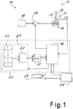
- Figure 1 shows, schematically, a test bench as a whole denoted by the number 10, produced by applying the principles of the invention.
- the bench 10 comprises a braking unit 11 equipped with a fitting 12 (possibly of the replaceable kind) for coupling with the corresponding end of a screwdriver 13 to be tested.
- the braking unit includes a brake 14 and a commonly known transducer unit or torque and angle sensor 15 connected to the brake (advantageously located between the fitting 12 and the brake 14).
- the brake is controlled by a control unit 16, advantageously produced using a commonly known system microprocessor which is suitably programmed, which controls the braking force of the brake according to predetermined torque/angle curves 17.
- control unit 16 receives information from the transducer unit 15 including the rotation angle and the torque transmitted, in order to both control the brake so as to apply torque providing a level of resistance based on the angle measured (following the said predetermined torque/angle curve simulating the screw) and to test the operating parameters of the screwdriver being tested.
- the type of brake control system employed by the control unit depends on the type of brake used.
- the control unit can control the delivery to the brake 14 of fluid under pressure from a suitable source 18 through a suitable electrically powered control valve 19, advantageously of a proportional kind.
- the invention described here is, however, applicable to any other type of brake usable for a test bench.
- the source 18 will be an electrical source and the valve 19 will be replaced by an electrical modulation system of the control power transmitted to the electromagnetic brake.
- the torque/angle braking curves 17 are sent to a control unit 16 by a selection unit 20 which, advantageously, comprises a memory 21 and a processing unit 22.
- the control unit 16 controls the selection unit 20 so as to obtain the brake control values (as a function of the angle measured) required for the desired screwdriver test operation.
- the braking curves 17 can be set in the memory 21, for example entirely point by point (with a very close series of pairs of torque and angle values), or the said curves can be set by storing solely some of the main points on the curve in the memory 21, or some representative values, and the intermediate values can be obtained through the use of suitable mathematical formulas for the interpolation of the trend of the curve between such points processed by the processing unit 22.
- the terms 'main points' or 'representative values' are intended as those points or the values on the curve from which the totality of the desired curve can be derived.
- the information to be stored in the memory 21 may consist solely of the coordinates of the points on the Cartesian plane marking the start, changes in gradient, and the end of each curve, and the trend between the points can be easily calculated mathematically by the processing unit as simply straight line segments linking pairs of successive main points.
- the mathematical formulas for interpolation can also be stored in the memory 21, associated with each curve (in the case, for example, that such formulas differ from one curve to another) or be programmed in the processing unit (in the case, for example, that such formulas are identical for all the curves or for a set of curves) so that the processing unit has to retrieve solely the main points (of the curve to be calculated) from the memory 21.
- This is, however, easily imaginable by persons skilled in the art in light of the description - provided herein - of the system according to the invention.
- processing unit 22 the control unit 16 and, possibly, also the memory 21 can be integrated within a single suitably programmed microprocessor-based processing system (denoted by 23), as is easily imaginable by a person skilled in the art.
- the control unit 16 is also advantageously connected to commonly known user interface peripherals such as a screen 24 (possibly of the touchscreen kind) and a keyboard 25, for entering commands and viewing results.
- user interface peripherals such as a screen 24 (possibly of the touchscreen kind) and a keyboard 25, for entering commands and viewing results.
- the user can select - through the user interface - an appropriate control curve for the brake depending on the screwdriver to be tested.
- selection can be made either by selecting a curve directly or by setting information about the screwdriver (such as the brand and model, serial number, type of use, etc.) which allows the control unit 16 to select the most appropriate test curve from the selection unit (and/or memory 17) or to propose test curves or test types from which the user can make the selection.
- Figure 2 shows the trend of a possible conventional braking curve 17 on the Cartesian plane of the torque based on the angle.
- This example curve is a classic polyline with point of origin 0 on the Cartesian plane and main points P1(C1, ⁇ 1), P2(C2, ⁇ 2), and Pmax(Cmax, ⁇ max).
- the first line segment between 0 and P1 represents the pre-tightening slope
- the second line segment between P1 and P2 represents the tightening slope
- the third line segment between P2 and Pmax represents the area of plastic behaviour.
- points P1, P2, and Pmax stored in memory 21
- the holder of the present application has found, however, that it is not always suitable in order to fully or, in any case, efficiently, test the correct calibration of a screwdriver.
- the sole reason for the test is to establish whether or not the calibration parameters of the screwdriver are correct at a much later point on the curve, for example, in the vicinity of the screw yield point or even beyond such yield point.
- the control unit 16 in the test bench according to the invention it is therefore also advantageously envisaged that it is possible to instruct the control unit 16 to select a braking action starting point somewhere on the braking curve other than 0 (i.e. other than the point at which torque is zero and the angle is zero).
- the brake is advantageously instructed to start from a desired torque value 'Cstart' which is not zero, rather than from the zero torque value.
- the screwdriver will therefore follow the curve from Cstart onwards.
- the entire braking curve is shifted to the left, on the Cartesian plane, so that the said curve intersects the vertical axis at the point with the predetermined Cstart torque value.
- the said Cstart value can be also usefully be stored in the memory 21, so that the processing unit 22 produces the new shifted curve 17 directly.
- it can also be the control unit 16 which - after receiving the normal curve 17 (starting at the origin) and the Cstart value, finds the angle value corresponding to the Cstart value on the curve and subtracts such angle value from the angle values gradually measured by the angle sensor 15 so as to obtain the torque values to be gradually transmitted to the brake, starting from Cstart.
- the torque/angle curve followed by the brake can be of the kind shown, by way of example, in Figure 3 .
- the Cstart value will depend on the pre-tightening (or tightening) value from which it is desired that the test be desired. This value can depend on the type of screwdriver and the normal use thereof, and even the (pre-)tightening value which the real screw would normally have when the screwdriver encounters the screw during use in the field.
- the Cstart value can, for example, be entered directly by the user via the user interface or set on the basis of information entered about the screwdriver (for example, brand and model, the serial number, type of use, etc.) which allows the control unit 16 to independently select the most suitable Cstart value or to propose Cstart values from which the user can make the selection.
- a method is advantageously applied according to which the brake 14 is instructed by the control unit 16 to follow, during a screwdriver test, a torque/angle curve 17 by setting a different starting Cstart torque value other than zero and following the torque/angle curve (17) from such Cstart value.
- the method comprises the initial step consisting of the storage - in the memory 21 of the bench - of one or more torque/angle curves 17 or values or points which are representative of such curves for the generation of the curves 17, with such curves starting from a torque value of zero with an angle value of zero.
- the desired curve for the screwdriver test is thus selected and the control unit shifts the curve so as to start from the Cstart torque value with a zero angle and controls the brake according to the shifted curve.
- test method according to the first aspect of the invention which envisages the possibility of starting the test from a desired torque value other than zero, a clear improvement was obtained in terms of flexibility and accuracy of the test bench compared with commonly known benches.
- the bench according to the invention may also advantageously comprise a further advantageous innovative feature regarding the braking curve followed by the test bench.
- the bench may envisage control of the brake by the control unit in order to use the said curve 17 also during a brake release phase, as well as during the normal braking step, as - meanwhile - occurs in the commonly known technique.
- the braking curve can be rendered bidirectional, in the sense that the brake is instructed to follow the braking curve for both increases in the angle ⁇ (measured by the angle sensor 15) and decreases in the said angle.
- This can be preferably limited, for example, to the progression of the curve up to the torque/angle value set as the start of the plastic behaviour of the screw simulated by the bench with the torque/angle curve.
- the method according to the invention using the curve bidirectionally has also been found to be particularly advantageous for successfully testing screwdrivers which have a tightening curve which involves momentary untightening movements during the tightening of a screw.
- a conventional test bench can misperform the screwdriver test.
- a conventional bench usually ends the test when it reaches the maximum torque value set for the screwdriver, completely releasing the brake so as to bring the latter back to zero for the start of the next test.
- the screwdriver were set to reach the maximum value by means of one or more slight untightening movements prior to the final tightening, such oscillations would not be managed properly by the joint simulated by the brake, and the measurement of the final torque value produced by the screwdriver prior to stopping would be out of line, i.e. if the screwdriver tested is electronic, the said screwdriver would detect the behaviour of the simulated joint during the untightening step as abnormal and would interrupt the tightening without reaching the final torque value, thereby preventing completion of the test.
- the joint is set by the control unit to the desired Cstart value at the start of the test but for negative angle values (from the zero angle point to the start of the test), the brake is activated to decrease braking action, following the braking curve selected "backwards", until the screwdriver resumes action in the tightening direction, resulting in the resumption of the braking curve route in the normal direction.
- the curve as shown by way of example in Figure 3 , can therefore be followed in both directions.
- the invention achieves the aims set by providing a bench and operating method therefor which allow a wide range of screwdrivers to be tested adequately and with great accuracy.
- the description set out above of an embodiment applying the innovative principles of the present invention is given by way of example of such innovative principles and therefore must not be deemed a limitation of the patent right claimed here.
- the braking curves produced and followed by the system can differ from those shown as examples in the drawings and can, for example, be formed of continuous curved lines rather than polylines, or can have a greater number of line segments, as easily imaginable by the person skilled in the art.
Landscapes
- Physics & Mathematics (AREA)
- General Physics & Mathematics (AREA)
- Details Of Spanners, Wrenches, And Screw Drivers And Accessories (AREA)
- Control Of Stepping Motors (AREA)
- Workshop Equipment, Work Benches, Supports, Or Storage Means (AREA)
Priority Applications (2)
| Application Number | Priority Date | Filing Date | Title |
|---|---|---|---|
| RS20190968A RS59096B1 (sr) | 2015-04-22 | 2016-04-18 | Ispitni sto za odvijač sa poboljšanom kontrolom |
| PL16726166T PL3286539T3 (pl) | 2015-04-22 | 2016-04-18 | Stanowisko do prób wkrętarek mające ulepszone sterowanie |
Applications Claiming Priority (2)
| Application Number | Priority Date | Filing Date | Title |
|---|---|---|---|
| ITUB2015A000428A ITUB20150428A1 (it) | 2015-04-22 | 2015-04-22 | Banco di test per avvitatore con controllo perfezionato |
| PCT/IB2016/052202 WO2016170462A1 (en) | 2015-04-22 | 2016-04-18 | Screwer test bench with improved control |
Publications (2)
| Publication Number | Publication Date |
|---|---|
| EP3286539A1 EP3286539A1 (en) | 2018-02-28 |
| EP3286539B1 true EP3286539B1 (en) | 2019-06-05 |
Family
ID=53490180
Family Applications (1)
| Application Number | Title | Priority Date | Filing Date |
|---|---|---|---|
| EP16726166.8A Active EP3286539B1 (en) | 2015-04-22 | 2016-04-18 | Screwer test bench with improved control |
Country Status (10)
| Country | Link |
|---|---|
| US (1) | US10641671B2 (pl) |
| EP (1) | EP3286539B1 (pl) |
| ES (1) | ES2737409T3 (pl) |
| HU (1) | HUE044464T2 (pl) |
| IT (1) | ITUB20150428A1 (pl) |
| PL (1) | PL3286539T3 (pl) |
| PT (1) | PT3286539T (pl) |
| RS (1) | RS59096B1 (pl) |
| TR (1) | TR201910787T4 (pl) |
| WO (1) | WO2016170462A1 (pl) |
Families Citing this family (3)
| Publication number | Priority date | Publication date | Assignee | Title |
|---|---|---|---|---|
| IT201600076117A1 (it) * | 2016-07-20 | 2018-01-20 | Atlas Copco Blm Srl | Sistema per controllare il corretto funzionamento di avvitatori industriali. |
| WO2022064352A1 (en) * | 2020-09-22 | 2022-03-31 | Scs Concept S.R.L. | Device for testing screwdrivers in automatic stations, test method and plant |
| US12571696B2 (en) * | 2020-12-03 | 2026-03-10 | Atlas Copco Industrial Technique Ab | Method to check the correct functioning of a tightening tool |
Family Cites Families (7)
| Publication number | Priority date | Publication date | Assignee | Title |
|---|---|---|---|---|
| IT1283158B1 (it) * | 1996-07-15 | 1998-04-07 | Blm S A S Di L Bareggi & C | Metodo e dispositivo di prova per avvitatori |
| DE50114947D1 (de) * | 2000-02-07 | 2009-08-06 | Kistler Holding Ag | Prüfgerät zur ermittlung der reib- und vorspannwerte von schraubenverbindungen |
| ITMI20011993A1 (it) * | 2001-09-25 | 2003-03-25 | Blm S A S Di L Bareggi & C | Banco di verifica di avvitatori comprendente un freno a disco sottile |
| ITMI20011992A1 (it) * | 2001-09-25 | 2003-03-25 | Blm S A S Di L Bareggi & C | Banco di verifica di avvitatori comprendente un dispositivo di frenatura per la simulazione della coppia rsistente |
| ITMI20011990A1 (it) * | 2001-09-25 | 2003-03-25 | Blm S A S Di L Bareggi & C | Banco di verifica di avvitatori comprendente un gruppo di simulazionedella coppia resistente |
| WO2007038769A1 (en) | 2005-09-28 | 2007-04-05 | Hetzel Adrian H | Electro-hydraulic timed angle controlled joint simulation torque calibration, certification and analysis device |
| ITMI20070072A1 (it) * | 2007-01-19 | 2008-07-20 | Atlas Copco Blm Srl | Dispositivo di rilevamento delle caratteristiche di coppia di un avvitatore |
-
2015
- 2015-04-22 IT ITUB2015A000428A patent/ITUB20150428A1/it unknown
-
2016
- 2016-04-18 US US15/564,279 patent/US10641671B2/en active Active
- 2016-04-18 TR TR2019/10787T patent/TR201910787T4/tr unknown
- 2016-04-18 PL PL16726166T patent/PL3286539T3/pl unknown
- 2016-04-18 PT PT16726166T patent/PT3286539T/pt unknown
- 2016-04-18 RS RS20190968A patent/RS59096B1/sr unknown
- 2016-04-18 EP EP16726166.8A patent/EP3286539B1/en active Active
- 2016-04-18 WO PCT/IB2016/052202 patent/WO2016170462A1/en not_active Ceased
- 2016-04-18 HU HUE16726166 patent/HUE044464T2/hu unknown
- 2016-04-18 ES ES16726166T patent/ES2737409T3/es active Active
Non-Patent Citations (1)
| Title |
|---|
| None * |
Also Published As
| Publication number | Publication date |
|---|---|
| PL3286539T3 (pl) | 2019-11-29 |
| PT3286539T (pt) | 2019-08-01 |
| US20180136060A1 (en) | 2018-05-17 |
| ES2737409T3 (es) | 2020-01-14 |
| WO2016170462A1 (en) | 2016-10-27 |
| US10641671B2 (en) | 2020-05-05 |
| HUE044464T2 (hu) | 2019-10-28 |
| TR201910787T4 (tr) | 2019-08-21 |
| EP3286539A1 (en) | 2018-02-28 |
| ITUB20150428A1 (it) | 2016-10-22 |
| RS59096B1 (sr) | 2019-09-30 |
Similar Documents
| Publication | Publication Date | Title |
|---|---|---|
| EP3286538B1 (en) | Screwer test bench with bidirectional control | |
| US11460824B2 (en) | Numerical controller | |
| US11531319B2 (en) | Failure prediction device and machine learning device | |
| EP3286539B1 (en) | Screwer test bench with improved control | |
| EP0911119A2 (en) | Method for determining the installed torque in a screw joint at impulse tightening and a torque impulse tool for tightening a screw joint to a predetermined torque level | |
| CN101932982A (zh) | 电动机控制特性评价装置及电动机控制特性的提示方法 | |
| ITTO20100683A1 (it) | Sistema predittivo di controllo e visualizzazione virtuale per una macchina utensile a controllo numerico | |
| KR20200056635A (ko) | 지능형 가공 시뮬레이션을 이용한 가공 공정 모니터링 시스템 및 이를 이용한 모니터링 방법 | |
| EP3488214B1 (en) | System for controlling the proper functioning of industrial screwdrivers | |
| EP1699600B1 (en) | Method for governing the operation of a pneumatic impulse wrench and a power screw joint tightening tool system | |
| US20080281533A1 (en) | Process and device for controlling the deformation of a metal part, in particular for redressing a metal part | |
| JP2021076395A (ja) | 診断装置 | |
| JP6730058B2 (ja) | パワーレンチのための制御システムおよび機器 | |
| KR101922729B1 (ko) | 건설기계의 전자 유압 제어장치 | |
| WO2005050493A3 (en) | Simulation system and computer-implemented method for simulation and verifying a control system | |
| SE543553C2 (sv) | Förfarande och arrangemang för att styra och kontrollera livslängden hos ett trädhanteringssystem vid en skogsmaskin | |
| EP1353293A3 (en) | Behavior control apparatus and method | |
| EP2368101B1 (en) | Method, device, system and computer program product for evaluating a power tool | |
| EP4256298B1 (en) | Method to check the correct functioning of a tightening tool | |
| KR101758375B1 (ko) | 기계설치를 위한 수평조정장치 | |
| KR100249772B1 (ko) | 건설기계 진단장치 | |
| KR102433963B1 (ko) | 기계식 건설 기계의 전자비례감압 밸브 제어 방법 및 이를 수행하기 위한 장치 | |
| SE0103258L (sv) | System för att kontrollera och övervaka fartygs påverkan samt medel härför | |
| KR20130031741A (ko) | 이상부분 추적이 가능한 차량 토크 제어방법 및 그 장치 |
Legal Events
| Date | Code | Title | Description |
|---|---|---|---|
| STAA | Information on the status of an ep patent application or granted ep patent |
Free format text: STATUS: THE INTERNATIONAL PUBLICATION HAS BEEN MADE |
|
| PUAI | Public reference made under article 153(3) epc to a published international application that has entered the european phase |
Free format text: ORIGINAL CODE: 0009012 |
|
| STAA | Information on the status of an ep patent application or granted ep patent |
Free format text: STATUS: REQUEST FOR EXAMINATION WAS MADE |
|
| 17P | Request for examination filed |
Effective date: 20171002 |
|
| AK | Designated contracting states |
Kind code of ref document: A1 Designated state(s): AL AT BE BG CH CY CZ DE DK EE ES FI FR GB GR HR HU IE IS IT LI LT LU LV MC MK MT NL NO PL PT RO RS SE SI SK SM TR |
|
| AX | Request for extension of the european patent |
Extension state: BA ME |
|
| DAV | Request for validation of the european patent (deleted) | ||
| DAX | Request for extension of the european patent (deleted) | ||
| REG | Reference to a national code |
Ref country code: DE Ref legal event code: R079 Ref document number: 602016014841 Country of ref document: DE Free format text: PREVIOUS MAIN CLASS: G01L0025000000 Ipc: G01L0005240000 |
|
| RIC1 | Information provided on ipc code assigned before grant |
Ipc: G01L 25/00 20060101ALI20181129BHEP Ipc: G01L 5/24 20060101AFI20181129BHEP |
|
| GRAP | Despatch of communication of intention to grant a patent |
Free format text: ORIGINAL CODE: EPIDOSNIGR1 |
|
| STAA | Information on the status of an ep patent application or granted ep patent |
Free format text: STATUS: GRANT OF PATENT IS INTENDED |
|
| INTG | Intention to grant announced |
Effective date: 20190108 |
|
| GRAS | Grant fee paid |
Free format text: ORIGINAL CODE: EPIDOSNIGR3 |
|
| RAP1 | Party data changed (applicant data changed or rights of an application transferred) |
Owner name: SCS CONCEPT S.R.L. |
|
| GRAA | (expected) grant |
Free format text: ORIGINAL CODE: 0009210 |
|
| STAA | Information on the status of an ep patent application or granted ep patent |
Free format text: STATUS: THE PATENT HAS BEEN GRANTED |
|
| AK | Designated contracting states |
Kind code of ref document: B1 Designated state(s): AL AT BE BG CH CY CZ DE DK EE ES FI FR GB GR HR HU IE IS IT LI LT LU LV MC MK MT NL NO PL PT RO RS SE SI SK SM TR |
|
| REG | Reference to a national code |
Ref country code: GB Ref legal event code: FG4D |
|
| REG | Reference to a national code |
Ref country code: CH Ref legal event code: EP |
|
| REG | Reference to a national code |
Ref country code: AT Ref legal event code: REF Ref document number: 1140498 Country of ref document: AT Kind code of ref document: T Effective date: 20190615 |
|
| REG | Reference to a national code |
Ref country code: IE Ref legal event code: FG4D |
|
| REG | Reference to a national code |
Ref country code: DE Ref legal event code: R096 Ref document number: 602016014841 Country of ref document: DE |
|
| REG | Reference to a national code |
Ref country code: CH Ref legal event code: NV Representative=s name: VALIPAT S.A. C/O BOVARD SA NEUCHATEL, CH |
|
| REG | Reference to a national code |
Ref country code: PT Ref legal event code: SC4A Ref document number: 3286539 Country of ref document: PT Date of ref document: 20190801 Kind code of ref document: T Free format text: AVAILABILITY OF NATIONAL TRANSLATION Effective date: 20190725 |
|
| REG | Reference to a national code |
Ref country code: NL Ref legal event code: FP |
|
| REG | Reference to a national code |
Ref country code: SE Ref legal event code: TRGR |
|
| REG | Reference to a national code |
Ref country code: LT Ref legal event code: MG4D |
|
| REG | Reference to a national code |
Ref country code: HU Ref legal event code: AG4A Ref document number: E044464 Country of ref document: HU |
|
| PG25 | Lapsed in a contracting state [announced via postgrant information from national office to epo] |
Ref country code: LT Free format text: LAPSE BECAUSE OF FAILURE TO SUBMIT A TRANSLATION OF THE DESCRIPTION OR TO PAY THE FEE WITHIN THE PRESCRIBED TIME-LIMIT Effective date: 20190605 Ref country code: NO Free format text: LAPSE BECAUSE OF FAILURE TO SUBMIT A TRANSLATION OF THE DESCRIPTION OR TO PAY THE FEE WITHIN THE PRESCRIBED TIME-LIMIT Effective date: 20190905 Ref country code: HR Free format text: LAPSE BECAUSE OF FAILURE TO SUBMIT A TRANSLATION OF THE DESCRIPTION OR TO PAY THE FEE WITHIN THE PRESCRIBED TIME-LIMIT Effective date: 20190605 Ref country code: AL Free format text: LAPSE BECAUSE OF FAILURE TO SUBMIT A TRANSLATION OF THE DESCRIPTION OR TO PAY THE FEE WITHIN THE PRESCRIBED TIME-LIMIT Effective date: 20190605 |
|
| REG | Reference to a national code |
Ref country code: SK Ref legal event code: T3 Ref document number: E 31785 Country of ref document: SK |
|
| PG25 | Lapsed in a contracting state [announced via postgrant information from national office to epo] |
Ref country code: GR Free format text: LAPSE BECAUSE OF FAILURE TO SUBMIT A TRANSLATION OF THE DESCRIPTION OR TO PAY THE FEE WITHIN THE PRESCRIBED TIME-LIMIT Effective date: 20190906 Ref country code: BG Free format text: LAPSE BECAUSE OF FAILURE TO SUBMIT A TRANSLATION OF THE DESCRIPTION OR TO PAY THE FEE WITHIN THE PRESCRIBED TIME-LIMIT Effective date: 20190905 Ref country code: LV Free format text: LAPSE BECAUSE OF FAILURE TO SUBMIT A TRANSLATION OF THE DESCRIPTION OR TO PAY THE FEE WITHIN THE PRESCRIBED TIME-LIMIT Effective date: 20190605 |
|
| REG | Reference to a national code |
Ref country code: ES Ref legal event code: FG2A Ref document number: 2737409 Country of ref document: ES Kind code of ref document: T3 Effective date: 20200114 |
|
| PG25 | Lapsed in a contracting state [announced via postgrant information from national office to epo] |
Ref country code: EE Free format text: LAPSE BECAUSE OF FAILURE TO SUBMIT A TRANSLATION OF THE DESCRIPTION OR TO PAY THE FEE WITHIN THE PRESCRIBED TIME-LIMIT Effective date: 20190605 Ref country code: RO Free format text: LAPSE BECAUSE OF FAILURE TO SUBMIT A TRANSLATION OF THE DESCRIPTION OR TO PAY THE FEE WITHIN THE PRESCRIBED TIME-LIMIT Effective date: 20190605 |
|
| PG25 | Lapsed in a contracting state [announced via postgrant information from national office to epo] |
Ref country code: IS Free format text: LAPSE BECAUSE OF FAILURE TO SUBMIT A TRANSLATION OF THE DESCRIPTION OR TO PAY THE FEE WITHIN THE PRESCRIBED TIME-LIMIT Effective date: 20191005 Ref country code: SM Free format text: LAPSE BECAUSE OF FAILURE TO SUBMIT A TRANSLATION OF THE DESCRIPTION OR TO PAY THE FEE WITHIN THE PRESCRIBED TIME-LIMIT Effective date: 20190605 |
|
| REG | Reference to a national code |
Ref country code: DE Ref legal event code: R097 Ref document number: 602016014841 Country of ref document: DE |
|
| PLBE | No opposition filed within time limit |
Free format text: ORIGINAL CODE: 0009261 |
|
| STAA | Information on the status of an ep patent application or granted ep patent |
Free format text: STATUS: NO OPPOSITION FILED WITHIN TIME LIMIT |
|
| PG25 | Lapsed in a contracting state [announced via postgrant information from national office to epo] |
Ref country code: DK Free format text: LAPSE BECAUSE OF FAILURE TO SUBMIT A TRANSLATION OF THE DESCRIPTION OR TO PAY THE FEE WITHIN THE PRESCRIBED TIME-LIMIT Effective date: 20190605 |
|
| 26N | No opposition filed |
Effective date: 20200306 |
|
| PG25 | Lapsed in a contracting state [announced via postgrant information from national office to epo] |
Ref country code: SI Free format text: LAPSE BECAUSE OF FAILURE TO SUBMIT A TRANSLATION OF THE DESCRIPTION OR TO PAY THE FEE WITHIN THE PRESCRIBED TIME-LIMIT Effective date: 20190605 |
|
| PG25 | Lapsed in a contracting state [announced via postgrant information from national office to epo] |
Ref country code: MC Free format text: LAPSE BECAUSE OF FAILURE TO SUBMIT A TRANSLATION OF THE DESCRIPTION OR TO PAY THE FEE WITHIN THE PRESCRIBED TIME-LIMIT Effective date: 20190605 |
|
| PG25 | Lapsed in a contracting state [announced via postgrant information from national office to epo] |
Ref country code: LU Free format text: LAPSE BECAUSE OF NON-PAYMENT OF DUE FEES Effective date: 20200418 |
|
| REG | Reference to a national code |
Ref country code: AT Ref legal event code: UEP Ref document number: 1140498 Country of ref document: AT Kind code of ref document: T Effective date: 20190605 |
|
| PG25 | Lapsed in a contracting state [announced via postgrant information from national office to epo] |
Ref country code: IE Free format text: LAPSE BECAUSE OF NON-PAYMENT OF DUE FEES Effective date: 20200418 |
|
| PG25 | Lapsed in a contracting state [announced via postgrant information from national office to epo] |
Ref country code: MT Free format text: LAPSE BECAUSE OF FAILURE TO SUBMIT A TRANSLATION OF THE DESCRIPTION OR TO PAY THE FEE WITHIN THE PRESCRIBED TIME-LIMIT Effective date: 20190605 Ref country code: CY Free format text: LAPSE BECAUSE OF FAILURE TO SUBMIT A TRANSLATION OF THE DESCRIPTION OR TO PAY THE FEE WITHIN THE PRESCRIBED TIME-LIMIT Effective date: 20190605 |
|
| PG25 | Lapsed in a contracting state [announced via postgrant information from national office to epo] |
Ref country code: MK Free format text: LAPSE BECAUSE OF FAILURE TO SUBMIT A TRANSLATION OF THE DESCRIPTION OR TO PAY THE FEE WITHIN THE PRESCRIBED TIME-LIMIT Effective date: 20190605 |
|
| P01 | Opt-out of the competence of the unified patent court (upc) registered |
Effective date: 20230625 |
|
| PGFP | Annual fee paid to national office [announced via postgrant information from national office to epo] |
Ref country code: NL Payment date: 20250427 Year of fee payment: 10 |
|
| PGFP | Annual fee paid to national office [announced via postgrant information from national office to epo] |
Ref country code: FI Payment date: 20250425 Year of fee payment: 10 |
|
| PGFP | Annual fee paid to national office [announced via postgrant information from national office to epo] |
Ref country code: DE Payment date: 20250429 Year of fee payment: 10 Ref country code: PL Payment date: 20250402 Year of fee payment: 10 |
|
| PGFP | Annual fee paid to national office [announced via postgrant information from national office to epo] |
Ref country code: GB Payment date: 20250428 Year of fee payment: 10 Ref country code: ES Payment date: 20250505 Year of fee payment: 10 |
|
| PGFP | Annual fee paid to national office [announced via postgrant information from national office to epo] |
Ref country code: HU Payment date: 20250422 Year of fee payment: 10 Ref country code: RS Payment date: 20250402 Year of fee payment: 10 |
|
| PGFP | Annual fee paid to national office [announced via postgrant information from national office to epo] |
Ref country code: BE Payment date: 20250428 Year of fee payment: 10 Ref country code: IT Payment date: 20250424 Year of fee payment: 10 |
|
| PGFP | Annual fee paid to national office [announced via postgrant information from national office to epo] |
Ref country code: PT Payment date: 20250401 Year of fee payment: 10 |
|
| PGFP | Annual fee paid to national office [announced via postgrant information from national office to epo] |
Ref country code: FR Payment date: 20250425 Year of fee payment: 10 |
|
| PGFP | Annual fee paid to national office [announced via postgrant information from national office to epo] |
Ref country code: CH Payment date: 20250501 Year of fee payment: 10 |
|
| PGFP | Annual fee paid to national office [announced via postgrant information from national office to epo] |
Ref country code: AT Payment date: 20250402 Year of fee payment: 10 |
|
| PGFP | Annual fee paid to national office [announced via postgrant information from national office to epo] |
Ref country code: TR Payment date: 20250418 Year of fee payment: 10 |
|
| PGFP | Annual fee paid to national office [announced via postgrant information from national office to epo] |
Ref country code: CZ Payment date: 20250407 Year of fee payment: 10 |
|
| PGFP | Annual fee paid to national office [announced via postgrant information from national office to epo] |
Ref country code: SE Payment date: 20250430 Year of fee payment: 10 |
|
| PGFP | Annual fee paid to national office [announced via postgrant information from national office to epo] |
Ref country code: SK Payment date: 20260331 Year of fee payment: 11 |