EP3285985B1 - Plastic tube bending method and apparatus - Google Patents
Plastic tube bending method and apparatus Download PDFInfo
- Publication number
- EP3285985B1 EP3285985B1 EP16782414.3A EP16782414A EP3285985B1 EP 3285985 B1 EP3285985 B1 EP 3285985B1 EP 16782414 A EP16782414 A EP 16782414A EP 3285985 B1 EP3285985 B1 EP 3285985B1
- Authority
- EP
- European Patent Office
- Prior art keywords
- tube
- bending
- cooling
- bend
- heating
- Prior art date
- Legal status (The legal status is an assumption and is not a legal conclusion. Google has not performed a legal analysis and makes no representation as to the accuracy of the status listed.)
- Active
Links
- 238000005452 bending Methods 0.000 title claims description 102
- 238000000034 method Methods 0.000 title claims description 27
- 239000004033 plastic Substances 0.000 title claims description 17
- 238000001816 cooling Methods 0.000 claims description 88
- 238000010438 heat treatment Methods 0.000 claims description 76
- 238000005520 cutting process Methods 0.000 claims description 14
- 239000000463 material Substances 0.000 claims description 9
- 230000000712 assembly Effects 0.000 claims 3
- 238000000429 assembly Methods 0.000 claims 3
- 239000004677 Nylon Substances 0.000 description 17
- 229920001778 nylon Polymers 0.000 description 17
- 238000004519 manufacturing process Methods 0.000 description 9
- 230000008569 process Effects 0.000 description 8
- 230000008901 benefit Effects 0.000 description 4
- 230000009977 dual effect Effects 0.000 description 3
- XLYOFNOQVPJJNP-UHFFFAOYSA-N water Substances O XLYOFNOQVPJJNP-UHFFFAOYSA-N 0.000 description 3
- 238000005485 electric heating Methods 0.000 description 2
- 239000000446 fuel Substances 0.000 description 2
- 239000007788 liquid Substances 0.000 description 2
- 238000012546 transfer Methods 0.000 description 2
- 239000004952 Polyamide Substances 0.000 description 1
- 229910000831 Steel Inorganic materials 0.000 description 1
- 230000004913 activation Effects 0.000 description 1
- 239000000654 additive Substances 0.000 description 1
- 230000000996 additive effect Effects 0.000 description 1
- 230000003466 anti-cipated effect Effects 0.000 description 1
- 230000008859 change Effects 0.000 description 1
- 239000007795 chemical reaction product Substances 0.000 description 1
- 238000007796 conventional method Methods 0.000 description 1
- 238000012937 correction Methods 0.000 description 1
- 238000011161 development Methods 0.000 description 1
- 238000006073 displacement reaction Methods 0.000 description 1
- 230000006698 induction Effects 0.000 description 1
- 238000013101 initial test Methods 0.000 description 1
- 230000007246 mechanism Effects 0.000 description 1
- 238000005457 optimization Methods 0.000 description 1
- 229920002647 polyamide Polymers 0.000 description 1
- 230000009467 reduction Effects 0.000 description 1
- 238000007670 refining Methods 0.000 description 1
- 229920005989 resin Polymers 0.000 description 1
- 239000011347 resin Substances 0.000 description 1
- 239000010959 steel Substances 0.000 description 1
- 238000012360 testing method Methods 0.000 description 1
Images


Classifications
-
- B—PERFORMING OPERATIONS; TRANSPORTING
- B29—WORKING OF PLASTICS; WORKING OF SUBSTANCES IN A PLASTIC STATE IN GENERAL
- B29C—SHAPING OR JOINING OF PLASTICS; SHAPING OF MATERIAL IN A PLASTIC STATE, NOT OTHERWISE PROVIDED FOR; AFTER-TREATMENT OF THE SHAPED PRODUCTS, e.g. REPAIRING
- B29C53/00—Shaping by bending, folding, twisting, straightening or flattening; Apparatus therefor
- B29C53/02—Bending or folding
- B29C53/08—Bending or folding of tubes or other profiled members
- B29C53/083—Bending or folding of tubes or other profiled members bending longitudinally, i.e. modifying the curvature of the tube axis
-
- B—PERFORMING OPERATIONS; TRANSPORTING
- B29—WORKING OF PLASTICS; WORKING OF SUBSTANCES IN A PLASTIC STATE IN GENERAL
- B29C—SHAPING OR JOINING OF PLASTICS; SHAPING OF MATERIAL IN A PLASTIC STATE, NOT OTHERWISE PROVIDED FOR; AFTER-TREATMENT OF THE SHAPED PRODUCTS, e.g. REPAIRING
- B29C53/00—Shaping by bending, folding, twisting, straightening or flattening; Apparatus therefor
- B29C53/80—Component parts, details or accessories; Auxiliary operations
- B29C53/84—Heating or cooling
-
- B—PERFORMING OPERATIONS; TRANSPORTING
- B29—WORKING OF PLASTICS; WORKING OF SUBSTANCES IN A PLASTIC STATE IN GENERAL
- B29C—SHAPING OR JOINING OF PLASTICS; SHAPING OF MATERIAL IN A PLASTIC STATE, NOT OTHERWISE PROVIDED FOR; AFTER-TREATMENT OF THE SHAPED PRODUCTS, e.g. REPAIRING
- B29C35/00—Heating, cooling or curing, e.g. crosslinking or vulcanising; Apparatus therefor
- B29C35/16—Cooling
- B29C2035/1658—Cooling using gas
- B29C2035/1666—Cooling using gas dried air
-
- B—PERFORMING OPERATIONS; TRANSPORTING
- B29—WORKING OF PLASTICS; WORKING OF SUBSTANCES IN A PLASTIC STATE IN GENERAL
- B29C—SHAPING OR JOINING OF PLASTICS; SHAPING OF MATERIAL IN A PLASTIC STATE, NOT OTHERWISE PROVIDED FOR; AFTER-TREATMENT OF THE SHAPED PRODUCTS, e.g. REPAIRING
- B29C35/00—Heating, cooling or curing, e.g. crosslinking or vulcanising; Apparatus therefor
- B29C35/16—Cooling
-
- B—PERFORMING OPERATIONS; TRANSPORTING
- B29—WORKING OF PLASTICS; WORKING OF SUBSTANCES IN A PLASTIC STATE IN GENERAL
- B29L—INDEXING SCHEME ASSOCIATED WITH SUBCLASS B29C, RELATING TO PARTICULAR ARTICLES
- B29L2023/00—Tubular articles
- B29L2023/004—Bent tubes
-
- B—PERFORMING OPERATIONS; TRANSPORTING
- B29—WORKING OF PLASTICS; WORKING OF SUBSTANCES IN A PLASTIC STATE IN GENERAL
- B29L—INDEXING SCHEME ASSOCIATED WITH SUBCLASS B29C, RELATING TO PARTICULAR ARTICLES
- B29L2023/00—Tubular articles
- B29L2023/22—Tubes or pipes, i.e. rigid
Definitions
- This invention relates to bending of plastic tubes, particularly nylon tubes but not necessarily limited to the same, and particularly as applied to automotive applications, appliances and other commercial or industrial applications, but not necessarily limited to the same.
- nylon may be used in referring to the plastic tube material.
- the expression is intended to include other plastic tube materials, including for example resin, polyamide or nylon-based materials.
- plastic/nylon tubes are used to convey liquids and vapors in many applications, including automotive applications. These tubes are semi-rigid with very stable properties under various conditions of heat and light, and are therefore suitable for conveying liquids, including fuels and fuel vapors.
- the tube in these applications, so that the tube can be properly routed, it usually needs to be formed to a specific contour, i.e. with various bend radii, bend angles, bend rotations, and distances between bends.
- This forming process requires a staged sequence of heating, bending and cooling.
- United States patent no. 5,516, 479 (Schimmelpfennig et al. ) is a typical prior art example, in which a pipe section is heated in a water bath and then laid around one or more bending plates, then further heated (for example by hot air), then cooled from inside the pipe with cold compressed air, then further cooled in a cold water bath. There is no bending and cooling at one bend location while a next bend location is heated for bending, and once configured, the apparatus cannot be readily reconfigured for different pipe configurations.
- the method and apparatus ideally would have a reasonably small footprint, and a short cycle time for each bend.
- a principal object of the present invention is to create a readily reconfigurable method and apparatus for bending plastic/nylon tubes.
- a plastic tube is formed using the conventional method of a staged sequence of heating, bending and cooling.
- the means by which this is accomplished is flexible to facilitate initial setup, as well as reconfiguration for different contours.
- the plastic tube is bent by first advancing the tube to position a desired first bend location of the tube at a bending and cooling station, the bend location of the tube having been previously heated by a tube heating assembly sufficiently for bending. Then the tube heating assembly is moved to a next desired bend location of the tube. Bending and cooling of the tube at the first bend location, and heating at the next desired bend location, then take place with the time window for the bending and cooling overlapping with the time window for heating at the next bend location. The tube is then advanced to position said next desired bend location at the bending/cooling station, and is rotated if/as necessary for the desired next bend orientation. These steps are repeated until all desired bends have been completed. As a result of the overlapping time windows, the total cycle time for heating, bending and cooling is substantially reduced compared to carrying out heating, bending and cooling sequentially.
- Preferred apparatus for carrying out the method of the invention has a base; a bending/cooling station mounted on the base, including means for bending and cooling the tube; a tube clamping assembly mounted on a track on the base, movable towards and away from the bending/cooling station, and including tube clamping fingers for gripping the plastic tube to advance it through the bending/cooling station, and a tube rotation assembly for rotating the tube; a tube heating assembly mounted on the track, between the bending/cooling station and the tube clamping assembly, including means for heating the tube; respective servomotors for moving the tube clamping assembly on the track, for moving the tube heating assembly on the track, for rotating the tube clamping fingers to rotate the tube, and for actuating a pivoting bending die at the bending/cooling station to bend the tube on a bend radius locate die; and programmable control means to monitor and control the servomotors and heating and cooling temperatures and times, including moving the tube heating assembly to a position to heat a next bend location while the tube is bent at
- all bending functions of the machine are accomplished using servomotors.
- the tube is held in its straight form, and is advanced through each heating, bending and cooling step in series until a final contour is complete.
- the bending/cooling station includes means to accommodate at least two different bend radii sizes, selectable through programmable means.
- a tube cutting system is also provided, to cut the tube to the desired length after its last bend is accomplished.
- pre-cut lengths can be used, and loaded manually or from a feeder.
- Each individual bend contour requires a separate heating and cooling function in addition to bend tooling actuation.
- Tube contours with multiple bends require multiple forming sequences applied in series.
- Minimized time allotments for heating and cooling are particularly important and are addressed in this invention by having heating for one bend taking place at least partially contemporaneously with cooling of the previous bend, so that overall cycle time is minimized.
- Figure 1 shows a preferred example of the overall apparatus for bending the tube 1, which may be a pre-cut length, or which may be supplied from a roll 3 (shown only schematically).
- the apparatus includes a base 2, supporting a tube indexing assembly 10, a tube heating assembly 20 , a tube bending/cooling assembly 30 , and a tube cutting assembly 40 .
- the tube indexing assembly 10 , and the tube heating assembly 20 and tube cutting assembly 40 move along tracks 5 .
- FIG. 2 shows the tube indexing system 10 .
- the tube 1 is clamped by tube clamping fingers 11 in a tube clamping assembly 12 , rotatably mounted on a carriage 13 .
- the tube clamping fingers are activated to grip the tube.
- the carriage 13 is advanced towards the bending/cooling station 30 by a tube advance servomotor 14 , which drives a gear to move the carriage along a rack 15 mounted on one of the tracks 5 .
- a tube advance servomotor 14 controls the tube advance servomotor 14 determines the longitudinal position of the tube at the bending/cooling station 30 .
- the carriage 13 also carries a tube rotation servomotor 18 , directly coupled to a hollow shaft gearbox which holds the tube clamping assembly 12 .
- a tube rotation servomotor 18 directly coupled to a hollow shaft gearbox which holds the tube clamping assembly 12 .
- the tube rotation servomotor 18 controls the rotational orientation of the tube at the bending/cooling station 30 .
- the longitudinal position of the tube is controlled by the tube advance servomotor 14 .
- the hollow configuration allows for long tubes (from straight or coil configurations) to be loaded from behind the tube clamping fingers 11 , although in some embodiments pre-cut lengths could instead be loaded from the front.
- the tube clamping assembly 12 has interchangeable tooling to accommodate various tube diameters and allow for quite simple manual changeover.
- the disc 19 which has a central opening, may be switched out for a disc with a different diameter of opening, to accommodate a different diameter of tube.
- the disc does not have any particular operational function, other than to prevent the tube from dropping down between the clamping fingers 11 when they are opened.
- Figure 3 shows the tube heating assembly 20 , which is also controlled and driven along the rack 15 and the tracks 5 .
- An important aspect of the invention is that controlling the position of the tube heating assembly allows the next bend location to be heated by the tube heating assembly 20 while the current location is being bent at the bending/cooling station 30 . This parallel process greatly improves cycle time compared to having separate, sequential heating and cooling steps.
- Figure 3 illustrates the elements and functions of the tube heating assembly 20 .
- Compressed air is supplied to air ports 21 .
- the air passes over electric heating coils 22 and into hot air delivery manifolds 23 on either side of the tube so that the hot air completely envelops the tube.
- Figure 3a shows two of the manifolds in the heating position, with the others removed for clarity. Hot air exits the manifolds through exit holes 29 .
- a thermocouple 24 is mounted to monitor and allow for the control of the actual air temperature at its application point.
- the heater positioning servomotor 25 drives a gear to move the tube heating assembly carriage 26 to the location on the tube where the next bend will be.
- manifolds 23 are provided, so as to accommodate varying bend radii specifications. For example, a large bend radius will require a longer area of the tube to be heated than for a tight bend.
- the manifold advance and retract cylinders 27 are actuated to advance one or more manifolds, depending on the bend requirements, and the hot air brings the tube temperature to an ideal state for forming. Retraction of the manifolds also allows heating time to be controlled, which is highly desirable for optimizing tube forming temperature.
- the manifold advance and retract cylinders 27 provide a means to apply and remove heat for the correct time necessary to reach the desired forming temperature.
- a series of tube supports are individually lowered out of position by cam 28 to allow the carriage to pass by, as with the carriage of the tube indexing system 10.
- the nylon tube should be heated to a temperature in the range of about 180-240 Celsius. In this example of the invention, this heating is accomplished using a steady stream of hot air heated to about 250 Celsius. This heats the tube to the desired temperature range in approximately 10 seconds. Obviously the invention is not limited to this particular hot air temperature and heating time. Optimum temperatures and heating times are determined on a case-by-case basis for any given tube characteristics, through routine experimentation.
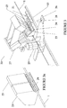
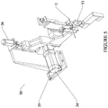
- Figures 4 and 5 show the bending/cooling station 30 .
- the station includes a dual set of bend radius locate dies, namely a small-radius die 31 and a larger-radius die 31' , a corresponding dual set of pivoting bending dies 32 and 32' , tube hold-down tooling 33 which is pneumatically actuated to move horizontally and vertically into a position to hold the tube straight during bending, and a bend actuation servomotor 34 which is connected to pivot the bending dies.
- the hold-down tooling is to counteract the tube wanting to lift just ahead of the bend radius locate dies as the bending dies are forming the desired bend.
- the bend radius locate dies 32 and 32' also serve as the cooling application tools, as described later below.
- Both the bend radius locate dies 31 and 31' and pivoting bending dies 32 and 32' are interchangeable to accommodate various tube diameters and bend radii and allow for manual changeover.
- Figures 6 to 6d further illustrate the tooling that applies each bend to the pre-heated tube 1 .
- Figures 6a to 6c in particular show the bending sequence.
- the pivoting bending die 32 moves along an arc relative to the bend radius locate die 31 .
- the pivoting bending die 32 is mounted so as to rotate freely on its axis, to prevent possible damage to the preheated tube.
- the pivoting bending die 32 produces the desired amount of bend angle at each bend.
- This function being actuated by a servomotor, i.e. by the bend actuation servomotor 34 , is an important aspect of the invention. This is because relaxation of the bend angle of the tube after bending is a known factor in bending plastic/nylon tube.
- the bend angle can be adjusted by controlling the bend actuation servomotor 34 , to accommodate relaxation in the bent tube angle.
- the pre-heat temperature parameter also affects bend angle relaxation; a tube that is heated to the correct forming temperature will require less over-bending to compensate for relaxation.
- temperature and servomotor bend angle are adjusted through routine experimentation, until a final stable and reproducible result is achieved. Being able to control the bend actuation via a servomotor greatly facilitates this routine experimentation, making it much easier to optimize production of a new part quickly.
- Figures 7a and 7b best show the side shift feature and vertical adjustment feature that allows the dual set of bend dies to alternate position, allowing greater flexibility for tubes that require two different bend radii. This is accomplished by air cylinder 35 that moves the dies horizontally and a servomotor 36 that moves the dies vertically into position, presenting the tube 1 for bending. Figure 7b in particular shows the two positions clearly.
- FIGS 7a and 7b show the plastic/nylon tube cooling application points.
- Compressed air that is chilled, is passed through ducts in the bend radius locate dies 31 and 31' .
- Each bend radius locate die provides three cooling ducts 61 , 61' and 61" (left, right and bottom respectively) where chilled air exits along the die where the bent tube lies. This creates a complete envelope of chilled air around the tube 1 .
- the temperature of the chilled air and its thorough application to the outside of the tube are important factors in how much time is required for the process of establishing the plastic/nylon tube in its bent position, and in obtaining a stable process with minimal cooling time. Shorter cooling times make manufacturing of higher quantity of tubes more viable.
- the tube is cooled before advancing it from the bending/cooling station 30 .
- this is accomplished using a steady stream of air cooled to about -25 Celsius or lower. This cools the tube sufficiently in approximately 10 seconds.
- the invention is not limited to this particular cooling air temperature and cooling time. As with heating the tube, optimum cooling temperatures and times are determined on a case-by-case basis for any given tube characteristics, through routine experimentation.
- the bending/cooling station preferably also includes thermocouple feedback, to aid in producing a stable manufacturing method.
- temperatures stated above are just examples which have been determined from initial testing only. Routine experimentation may determine narrower or wider preferred ranges of temperatures, and optimum temperatures or temperature ranges will vary according to the application and specific tube characteristics. Similarly, heating and cooling times may vary, with optimums to be determined according to routine experimentation.
- Figure 8 shows the tube cutting assembly 40 , described in greater detail below.
- An important advantage of the preferred embodiment of the invention is that long tubes (from straight or coil configurations) can be cut to length as part of the bending process with minimal operator involvement. As will be described later below, tubes pre-cut to the correct length can be loaded manually, automatically or semi-automatically, but incorporating a tube cutting system such as this one avoids that need and renders the process more efficient.
- the tube cutting system 40 is mounted to the tube heating assembly 20 which allows for programmable positioning along the length of the tube by way of the heater positioning servomotor 25 that drives a gear to move the tube heating assembly carriage 26 to the location on the tube where the next cut will be.
- the cutter is driven downward over the tube by air cylinder 71 , causing the knife blade 72 to sever the tube.
- programmable control means e.g. programmable logic controller (PLC) or PC-based programs
- PLC programmable logic controller
- various parameters including heating air temperature, heating time, cooling air temperature, cooling time, bend angle for each bend, rotation between bends, index distance between bends, and cutting position
- PLC programmable logic controller
- PC-based programs to provide key advantages at multiple stages.
- various parameters including heating air temperature, heating time, cooling air temperature, cooling time, bend angle for each bend, rotation between bends, index distance between bends, and cutting position
- various parameters including heating air temperature, heating time, cooling air temperature, cooling time, bend angle for each bend, rotation between bends, index distance between bends, and cutting position
- the parameters may need adjustment from time to time to deal with ambient conditions and material variations which are common in manufacturing settings.
- tubes pre-cut to the correct length can be loaded manually, automatically or semi-automatically.
- pre-cut tubes are presented, preferably by an automated loading system, to the front of the tube clamp fingers 11 .
- the automated loading system will accommodate various lengths and diameters of tube by storing them in varying quantities and subsequently dispensing individual tubes into the bending apparatus on demand.
- the completed parts will simply be allowed to fall into a bin once completed.
- the system can also be provided with an unloading system to transfer completed parts from the system to bins, racks, conveyors or the like, for example by using a telescoping arm with a gripping mechanism to grip the part just prior to cutting via the tube cutting assembly, and then transfer it to the desired location.
- a central source can be included in the apparatus to eliminate the multiple electric heating coils 22.
- This centralized source of heat would convey hot air to the hot air delivery ducts 23 by way of a series of pneumatic valves controlled by the PLC.
- Alternative cooling means could also be employed.
- Alternative chilled air sources may include, but are not limited to, vortex air chillers, thermo-electric air conditioners, compressor based air conditioners and the like.
- Figure 9 shows a nylon tube that was produced on a prototype of the preferred embodiment of the invention. It has five bends 101 to 105 , each bend processed as described herein.
- the plastic tube made of a nylon material known as PA-12, having an outside diameter of 8mm and an inside diameter of 6mm, was bent by applying air heated to 230°C for 6 to 8 seconds.
- the tube was cooled, in parallel with heating, by applying air at -25°C for 6 to 8 seconds.
- the specified bend radius was 32.0mm.
Description
- This invention relates to bending of plastic tubes, particularly nylon tubes but not necessarily limited to the same, and particularly as applied to automotive applications, appliances and other commercial or industrial applications, but not necessarily limited to the same.
- Throughout this specification, for convenience, the term "nylon" may be used in referring to the plastic tube material. However, except where the context dictates otherwise, the expression is intended to include other plastic tube materials, including for example resin, polyamide or nylon-based materials.
- Various plastic/nylon tubes are used to convey liquids and vapors in many applications, including automotive applications. These tubes are semi-rigid with very stable properties under various conditions of heat and light, and are therefore suitable for conveying liquids, including fuels and fuel vapors.
- In these applications, so that the tube can be properly routed, it usually needs to be formed to a specific contour, i.e. with various bend radii, bend angles, bend rotations, and distances between bends. This forming process requires a staged sequence of heating, bending and cooling.
- Many methods of forming plastic/nylon tubes using this sequence of heating, bending and cooling are currently in use. They generally use dedicated forming tools to produce one contour consisting of multiple bends of varying radii, bend angle, bend rotation, and distance between bends. The tube is heated using hot air or other means in its straight form, transferred into a steel forming tool or series of tools to bend the tube to the desired contour, cooled in place using cold air or water or other means, and removed having achieved the desired contour. Due to the dedicated nature of these bending methods, the tooling is expensive and generally not easily reconfigurable for different contours. Contour changes are very common, and are expensive and time consuming. This is disproportionately costly, especially for producing tubes in relatively low quantity. The dedicated tools and machines also require a large manufacturing space.
- United States patent no.
5,516, 479 (Schimmelpfennig et al. ) is a typical prior art example, in which a pipe section is heated in a water bath and then laid around one or more bending plates, then further heated (for example by hot air), then cooled from inside the pipe with cold compressed air, then further cooled in a cold water bath. There is no bending and cooling at one bend location while a next bend location is heated for bending, and once configured, the apparatus cannot be readily reconfigured for different pipe configurations. - In view of the preceding, there is a need for a readily reconfigurable method of bending plastic/nylon tubes which is effective and efficient, and for apparatus to carry out the same.
- In addition to being readily reconfigurable, the method and apparatus ideally would have a reasonably small footprint, and a short cycle time for each bend.
- Accordingly, in view of the above-described problems encountered in the prior art, a principal object of the present invention is to create a readily reconfigurable method and apparatus for bending plastic/nylon tubes. In the invention, a plastic tube is formed using the conventional method of a staged sequence of heating, bending and cooling. However the means by which this is accomplished is flexible to facilitate initial setup, as well as reconfiguration for different contours.
- In the method of the invention, the plastic tube is bent by first advancing the tube to position a desired first bend location of the tube at a bending and cooling station, the bend location of the tube having been previously heated by a tube heating assembly sufficiently for bending. Then the tube heating assembly is moved to a next desired bend location of the tube. Bending and cooling of the tube at the first bend location, and heating at the next desired bend location, then take place with the time window for the bending and cooling overlapping with the time window for heating at the next bend location. The tube is then advanced to position said next desired bend location at the bending/cooling station, and is rotated if/as necessary for the desired next bend orientation. These steps are repeated until all desired bends have been completed. As a result of the overlapping time windows, the total cycle time for heating, bending and cooling is substantially reduced compared to carrying out heating, bending and cooling sequentially.
- Preferred apparatus for carrying out the method of the invention has a base; a bending/cooling station mounted on the base, including means for bending and cooling the tube; a tube clamping assembly mounted on a track on the base, movable towards and away from the bending/cooling station, and including tube clamping fingers for gripping the plastic tube to advance it through the bending/cooling station, and a tube rotation assembly for rotating the tube; a tube heating assembly mounted on the track, between the bending/cooling station and the tube clamping assembly, including means for heating the tube; respective servomotors for moving the tube clamping assembly on the track, for moving the tube heating assembly on the track, for rotating the tube clamping fingers to rotate the tube, and for actuating a pivoting bending die at the bending/cooling station to bend the tube on a bend radius locate die; and programmable control means to monitor and control the servomotors and heating and cooling temperatures and times, including moving the tube heating assembly to a position to heat a next bend location while the tube is bent at a bend location.
- In preferred embodiments, all bending functions of the machine (distance between bends, rotation between bends, and angle of bend) are accomplished using servomotors. The tube is held in its straight form, and is advanced through each heating, bending and cooling step in series until a final contour is complete.
- Preferably, the bending/cooling station includes means to accommodate at least two different bend radii sizes, selectable through programmable means.
- Preferably, to facilitate continuous feeding of tubing from a roll instead of in discreet lengths, a tube cutting system is also provided, to cut the tube to the desired length after its last bend is accomplished. However, if desired, pre-cut lengths can be used, and loaded manually or from a feeder.
- Each individual bend contour requires a separate heating and cooling function in addition to bend tooling actuation. Tube contours with multiple bends require multiple forming sequences applied in series. Minimized time allotments for heating and cooling are particularly important and are addressed in this invention by having heating for one bend taking place at least partially contemporaneously with cooling of the previous bend, so that overall cycle time is minimized.
- Various tube diameters and bend radii are expected to be accommodated at different times, and preferred embodiments of the invention ensure that the physical changeover of tooling is optimized for user simplicity.
- Further details of the invention will be described or will become apparent in the course of the following detailed description and drawings of embodiments of the invention, being presented as examples only.
- Examples of the invention will now be described with reference to the accompanying drawings, in which:
-
Figure 1 is an overview of the apparatus in top view; -
Figure 2 is a perspective view of the tube indexing assembly; -
Figures 2a and 2b are perspective views to illustrate how movement of the carriage of the tube indexing assembly causes displacement of the tube supports; -
Figure 3 is a perspective view of the tube heating assembly; -
Figure 3a is a perspective view showing the hot air delivery manifolds; -
Figure 4 is a front perspective view of the tube bending/cooling assembly; -
Figure 5 is a rear perspective view of the tube bending/cooling assembly; -
Figure 6 is a perspective view showing the bending dies with the tube in position for a small-radius bend; -
Figures 6a to 6c are side view showing the bending sequence; -
Figure 6d is a perspective view similar toFigure 6 , but showing the bending dies with the tube in position for a large-radius bend; -
Figure 7a is a cross-sectional view showing the cooling ducts, and the tube in position for a small-radius bend; -
Figure 7b is a cross-sectional view similar toFigure 7a , but showing the bending/cooling assembly shifted to a position for a large-radius bend; -
Figure 8 is a perspective view of the tube cutting assembly; -
Figure 9 is a perspective view of an example of a nylon tube produced by the method and apparatus. -
Figure 1 shows a preferred example of the overall apparatus for bending thetube 1, which may be a pre-cut length, or which may be supplied from a roll 3 (shown only schematically). The apparatus includes abase 2, supporting atube indexing assembly 10, atube heating assembly 20, a tube bending/cooling assembly 30, and atube cutting assembly 40. Thetube indexing assembly 10, and thetube heating assembly 20 andtube cutting assembly 40, move along tracks 5. -
Figure 2 shows thetube indexing system 10. Thetube 1 is clamped bytube clamping fingers 11 in atube clamping assembly 12, rotatably mounted on acarriage 13. The tube clamping fingers are activated to grip the tube. Thecarriage 13 is advanced towards the bending/cooling station 30 by atube advance servomotor 14, which drives a gear to move the carriage along arack 15 mounted on one of the tracks 5. Thus controlling thetube advance servomotor 14 determines the longitudinal position of the tube at the bending/cooling station 30. - Long tubes require longitudinal support throughout the process, to allow the tube to remain in a horizontally linear profile for successful positioning in the bending/cooling station.. As
carriage 13 advances towards the bending/cooling station, a series of tube supports 16 are individually lowered out of position bycams 17 to allow the carriage to pass by. As seen best inFigs. 2a and 2b , thecams 17 come into contact withbars 171 which are connected to respective pivot blocks 172, to rotate the tube supports downwardly against the upward bias ofsprings 173. The length of the bars corresponds to how long the tube support has to be held down away from the carriage. - The
carriage 13 also carries atube rotation servomotor 18, directly coupled to a hollow shaft gearbox which holds thetube clamping assembly 12. Thus the rotational orientation of the tube at the bending/cooling station 30 is controlled by thetube rotation servomotor 18, and the longitudinal position of the tube is controlled by thetube advance servomotor 14. The hollow configuration allows for long tubes (from straight or coil configurations) to be loaded from behind thetube clamping fingers 11, although in some embodiments pre-cut lengths could instead be loaded from the front. - The
tube clamping assembly 12 has interchangeable tooling to accommodate various tube diameters and allow for quite simple manual changeover. Specifically, thedisc 19, which has a central opening, may be switched out for a disc with a different diameter of opening, to accommodate a different diameter of tube. The disc does not have any particular operational function, other than to prevent the tube from dropping down between the clampingfingers 11 when they are opened. -
Figure 3 shows thetube heating assembly 20, which is also controlled and driven along therack 15 and the tracks 5. An important aspect of the invention is that controlling the position of the tube heating assembly allows the next bend location to be heated by thetube heating assembly 20 while the current location is being bent at the bending/cooling station 30. This parallel process greatly improves cycle time compared to having separate, sequential heating and cooling steps. -
Figure 3 illustrates the elements and functions of thetube heating assembly 20. Compressed air is supplied toair ports 21. The air passes over electric heating coils 22 and into hot air delivery manifolds 23 on either side of the tube so that the hot air completely envelops the tube.Figure 3a shows two of the manifolds in the heating position, with the others removed for clarity. Hot air exits the manifolds through exit holes 29. Athermocouple 24 is mounted to monitor and allow for the control of the actual air temperature at its application point. When thetube 1 is advanced to the current bend position, theheater positioning servomotor 25 drives a gear to move the tubeheating assembly carriage 26 to the location on the tube where the next bend will be.Multiple manifolds 23 are provided, so as to accommodate varying bend radii specifications. For example, a large bend radius will require a longer area of the tube to be heated than for a tight bend. The manifold advance and retract cylinders 27 (one per manifold) are actuated to advance one or more manifolds, depending on the bend requirements, and the hot air brings the tube temperature to an ideal state for forming. Retraction of the manifolds also allows heating time to be controlled, which is highly desirable for optimizing tube forming temperature. - This heating process using hot air directed through multiple and independently actuated manifolds with thermocouple feedback, is highly advantageous in terms of producing a stable manufacturing method. The manifold advance and retract
cylinders 27 provide a means to apply and remove heat for the correct time necessary to reach the desired forming temperature. Ascarriage 26 advances towards the bending/cooling station, a series of tube supports are individually lowered out of position bycam 28 to allow the carriage to pass by, as with the carriage of thetube indexing system 10. - For optimal bending, the nylon tube should be heated to a temperature in the range of about 180-240 Celsius. In this example of the invention, this heating is accomplished using a steady stream of hot air heated to about 250 Celsius. This heats the tube to the desired temperature range in approximately 10 seconds. Obviously the invention is not limited to this particular hot air temperature and heating time. Optimum temperatures and heating times are determined on a case-by-case basis for any given tube characteristics, through routine experimentation.
-
Figures 4 and5 show the bending/cooling station 30. The station includes a dual set of bend radius locate dies, namely a small-radius die 31 and a larger-radius die 31', a corresponding dual set of pivoting bending dies 32 and 32', tube hold-down tooling 33 which is pneumatically actuated to move horizontally and vertically into a position to hold the tube straight during bending, and abend actuation servomotor 34 which is connected to pivot the bending dies. The hold-down tooling is to counteract the tube wanting to lift just ahead of the bend radius locate dies as the bending dies are forming the desired bend. - The bend radius locate dies 32 and 32' also serve as the cooling application tools, as described later below.
- Both the bend radius locate dies 31 and 31' and pivoting bending dies 32 and 32' are interchangeable to accommodate various tube diameters and bend radii and allow for manual changeover.
-
Figures 6 to 6d further illustrate the tooling that applies each bend to thepre-heated tube 1.Figures 6a to 6c in particular show the bending sequence. The pivoting bending die 32 moves along an arc relative to the bend radius locatedie 31. The pivoting bending die 32 is mounted so as to rotate freely on its axis, to prevent possible damage to the preheated tube. The pivoting bending die 32 produces the desired amount of bend angle at each bend. This function being actuated by a servomotor, i.e. by thebend actuation servomotor 34, is an important aspect of the invention. This is because relaxation of the bend angle of the tube after bending is a known factor in bending plastic/nylon tube. In this invention the bend angle can be adjusted by controlling thebend actuation servomotor 34, to accommodate relaxation in the bent tube angle. The pre-heat temperature parameter also affects bend angle relaxation; a tube that is heated to the correct forming temperature will require less over-bending to compensate for relaxation. When a specific tube part is programmed to produce a final tube contour these two parameters, temperature and servomotor bend angle, are adjusted through routine experimentation, until a final stable and reproducible result is achieved. Being able to control the bend actuation via a servomotor greatly facilitates this routine experimentation, making it much easier to optimize production of a new part quickly. -
Figures 7a and 7b best show the side shift feature and vertical adjustment feature that allows the dual set of bend dies to alternate position, allowing greater flexibility for tubes that require two different bend radii. This is accomplished byair cylinder 35 that moves the dies horizontally and aservomotor 36 that moves the dies vertically into position, presenting thetube 1 for bending.Figure 7b in particular shows the two positions clearly. -
Figures 7a and 7b show the plastic/nylon tube cooling application points. Compressed air, that is chilled, is passed through ducts in the bend radius locate dies 31 and 31'. Each bend radius locate die provides threecooling ducts tube 1. The temperature of the chilled air and its thorough application to the outside of the tube are important factors in how much time is required for the process of establishing the plastic/nylon tube in its bent position, and in obtaining a stable process with minimal cooling time. Shorter cooling times make manufacturing of higher quantity of tubes more viable. - The tube is cooled before advancing it from the bending/
cooling station 30. In this example of the invention, this is accomplished using a steady stream of air cooled to about -25 Celsius or lower. This cools the tube sufficiently in approximately 10 seconds. Obviously the invention is not limited to this particular cooling air temperature and cooling time. As with heating the tube, optimum cooling temperatures and times are determined on a case-by-case basis for any given tube characteristics, through routine experimentation. - The bending/cooling station preferably also includes thermocouple feedback, to aid in producing a stable manufacturing method.
- Notwithstanding the preceding, it must again be emphasized that the temperatures stated above, for both heating and cooling, are just examples which have been determined from initial testing only. Routine experimentation may determine narrower or wider preferred ranges of temperatures, and optimum temperatures or temperature ranges will vary according to the application and specific tube characteristics. Similarly, heating and cooling times may vary, with optimums to be determined according to routine experimentation.
-
Figure 8 shows thetube cutting assembly 40, described in greater detail below. An important advantage of the preferred embodiment of the invention is that long tubes (from straight or coil configurations) can be cut to length as part of the bending process with minimal operator involvement. As will be described later below, tubes pre-cut to the correct length can be loaded manually, automatically or semi-automatically, but incorporating a tube cutting system such as this one avoids that need and renders the process more efficient. - The
tube cutting system 40 is mounted to thetube heating assembly 20 which allows for programmable positioning along the length of the tube by way of theheater positioning servomotor 25 that drives a gear to move the tubeheating assembly carriage 26 to the location on the tube where the next cut will be. The cutter is driven downward over the tube byair cylinder 71, causing theknife blade 72 to sever the tube. - It is a specific advantage of the invention that because heating of the next bend location starts while the previous bend is being cooled, i.e. in overlapping time windows (as close to simultaneous as possible), the heating and cooling times are not additive. An overall cycle time in the range of approximately 10 to 15 seconds per bend is presently expected from the preferred embodiment, and may be reduced below that range with further routine experimental optimization of parameters. This reduction in cycle time obviously is especially important for higher volume manufacturing requirements.
- Central to optimal forming of nylon tubing by this invention is the ability to control the time that heating and cooling apparatus is applied to the tube, as well as other parameters such a heating and cooling air temperatures. The invention allows for optimally setting these parameters on a per bend basis and refining these parameters to achieve accurate and repeatable results.
- It is known that relaxation of nylon materials may occur at the time of bending and within 12-24 hours thereafter, due to the nature of these nylon materials. The invention allows for complete adjustability for bend position, angle and rotation using servomotors to compensate for anticipated or demonstrated relaxation of bend angle or rotation correction.
- An important feature of the invention and its stated purpose of flexibility (i.e. being readily reconfigurable) is the use of programmable control means, e.g. programmable logic controller (PLC) or PC-based programs, to provide key advantages at multiple stages. Firstly, various parameters (including heating air temperature, heating time, cooling air temperature, cooling time, bend angle for each bend, rotation between bends, index distance between bends, and cutting position) can be entered into the system during the development of a set of parameters for a particular tube contour. The process involves a sequence of setting these parameters and then testing and resetting them via routine experimentation until the desired end product result is achieved. Secondly, during manufacturing, the parameters may need adjustment from time to time to deal with ambient conditions and material variations which are common in manufacturing settings. Thirdly, change of contour requirements in automotive and other commercial and industrial settings is common. With dedicated equipment, making these changes is a costly undertaking, both in material and labor costs, plus involves time-consuming down time. With this invention, through revision of parameters in the algorithms for a particular tube contour, changes can made quickly and with little or no additional tooling cost. Furthermore, because the PLC can store multiple "recipes", i.e. parameter sets for given part numbers based on previous production, it is easy to switch from producing one part to producing another part, with no need to repeat the routine experimentation to re-establish the optimum parameters.
- As an alternative to continuous feeding of the tube and using a tube cutting system to cut the tubes within the system, tubes pre-cut to the correct length can be loaded manually, automatically or semi-automatically.
- In such an alternative, pre-cut tubes are presented, preferably by an automated loading system, to the front of the
tube clamp fingers 11. The automated loading system will accommodate various lengths and diameters of tube by storing them in varying quantities and subsequently dispensing individual tubes into the bending apparatus on demand. - In many applications, the completed parts will simply be allowed to fall into a bin once completed. However, if desired, the system can also be provided with an unloading system to transfer completed parts from the system to bins, racks, conveyors or the like, for example by using a telescoping arm with a gripping mechanism to grip the part just prior to cutting via the tube cutting assembly, and then transfer it to the desired location.
- As an alternative source of heat, a central source can be included in the apparatus to eliminate the multiple electric heating coils 22. This centralized source of heat would convey hot air to the hot
air delivery ducts 23 by way of a series of pneumatic valves controlled by the PLC. - Other alternative methods of heating the tube could be incorporated into the apparatus, such as including an ultrasonic tooling source that would replace the hot air delivery manifolds 23 on either side of the tube. High frequency induction or radiant heat could also be used.
- Alternative cooling means could also be employed. Alternative chilled air sources may include, but are not limited to, vortex air chillers, thermo-electric air conditioners, compressor based air conditioners and the like.
- As an example,
Figure 9 shows a nylon tube that was produced on a prototype of the preferred embodiment of the invention. It has fivebends 101 to 105, each bend processed as described herein. - The plastic tube, made of a nylon material known as PA-12, having an outside diameter of 8mm and an inside diameter of 6mm, was bent by applying air heated to 230°C for 6 to 8 seconds. The tube was cooled, in parallel with heating, by applying air at -25°C for 6 to 8 seconds. Including time for tube indexing and bend activation, the overall cycle time to produce the bent part was 60 seconds. The specified bend radius was 32.0mm.
- It will be evident to those knowledgeable in the field of the invention that many variations on the examples described above are conceivable within the scope of the invention. It should therefore be understood that the claims which define the invention are not restricted to the specific examples described above.
- Further variations may be apparent or become apparent to those knowledgeable in the field of the invention, within the scope of the invention as defined by the claims which follow.
Claims (18)
- A method of bending a plastic tube (1), comprising the steps of:a. advancing the tube (1) to position a desired first bend location (105) of the tube (1) at a bending and cooling station (30), the bend location of the tube (1) having been previously heated by a tube heating assembly (20) sufficiently for bending;b. moving said tube heating assembly (20) to a next desired bend location (104) of the tube (1);c. bending and cooling the tube (1) at the first bend location (105), and heating said next desired bend location (104) with said tube heating assembly (20) sufficiently for bending, such that a time window for said bending and cooling at said first bend location (105) overlaps with a time window for heating at said next bend location (104);d. advancing the tube (1) to position said next desired bend location (104) of the tube (1) at said bending and cooling station (30), and rotating the tube (1) if/as necessary for the desired next bend orientation; ande. repeating steps b., c. and d. until all desired bends have been completed;whereby total cycle time for heating, bending and cooling is substantially reduced compared to carrying out heating, bending and cooling sequentially.
- The method of claim 1, where said cooling of the tube (1) at said bending and cooling station (30) is by application of chilled air applied so as to envelop the tube (1) in said bending and cooling station (30).
- The method of claim 1, where said heating of the tube (1) by said tube heating assembly (20) is by application of heated air applied so as to envelop the tube (1) in said tube heating assembly (20).
- The method of claim 1, where said cooling of the tube (1) at said bending and cooling station (30) is by application of chilled air applied so as to envelop the tube in said bending and cooling station (30), and where said heating of the tube (1) by said tube heating assembly (20) is by application of heated air applied so as to envelop the tube (1) in said tube heating assembly (20).
- The method of claim 3, wherein the heated air is supplied to said tube heating assembly (20) by selectable manifolds (23) such that heated air may be applied to varying lengths of tube (1) by selecting which manifolds (23) are used to supply the heated air.
- The method of claim 4, wherein the heated air is supplied to said tube heating assembly (20) by selectable manifolds (23) such that heated air may be applied to varying lengths of tube (1) by selecting which manifolds (23) are used to supply the heated air.
- The method of either claim 4 or claim 6, where the temperatures of said chilled air and of said heated air are monitored by thermocouples (24) and are controlled by programmable control means.
- The method of any one of claims 1 to 7, where heating time, cooling time, bend angle for each bend, tube rotation between bends, and distance between bends are controlled by programmable control means.
- The method of any one of claims 1 to 8, where at least advancing said tube (1), rotating said tube (1), moving said heating assembly (20), and bending said tube (1), are carried out by operation of servomotors (14, 18, 25, 34, 36) controlled by programmable control means.
- Apparatus for bending a plastic tube (1) by carrying out the steps of:a. advancing the tube (1) to position a desired first bend location (105) of the tube (1) at a bending and cooling station (30), the bend location of the tube (1) having been previously heated by a tube heating assembly (20) sufficiently for bending;b. moving said tube heating assembly (20) to a next desired bend location (104) of the tube (1);c. bending and cooling the tube (1) at the first bend location (105), and heating said next desired bend location (104) with said tube heating assembly (20) sufficiently for bending, such that a time window for said bending and cooling at said first bend location (105) overlaps with a time window for heating at said next bend location (104);d. advancing the tube (1) to position said next desired bend location (104) of the tube (1) at said bending and cooling station, and rotating the tube (1) if/as necessary for the desired next bend orientation; ande. repeating steps b., c. and d. until all desired bends have been completed;
said apparatus comprising:a base (2);said bending and cooling station (30) mounted on said base (2), said bending and cooling station (30) including means (31, 31', 32, 32') for bending and cooling the tube (1);a tube clamping assembly (12) mounted on a track (5) on said base (2), movable towards and away from said bending and cooling station (30), said tube clamping assembly (12) including tube clamping means (11) for gripping said tube (1), and a tube rotation assembly (18) connected to rotate said gripping means to axially rotate the tube (1);a tube heating assembly (20) mounted for movement between said bending and cooling station (30) and said tube clamping assembly (12), including means (23, 29) for heating the tube (1);respective servomotors (14, 25, 18, 34) connected for moving said tube clamping assembly (12), for moving said tube heating assembly (20), for rotating said tube clamping means (11) to rotate said tube (1), and for actuating said means for bending at said bending and cooling station (30), to bend said tube (1); andprogrammable control means programmed and connected to control said servomotors (14, 25, 18, 34). - Apparatus as in claim 10, where said means for bending the tube (1) at said bending and cooling station (30) comprises at least one bending and cooling assembly, each said bending and cooling assembly comprising a pivoting bending die (32, 32') for bending said tube (1) around a bend radius locate die (31, 31'), and means (61, 61', 61") for cooling said tube (1).
- Apparatus as in claim 11, where said means for cooling said tube (1) comprises cold air routed to envelop said tube (1) in said bending and cooling station (30).
- Apparatus as in either claim 11 or claim 12, where there are two said bending and cooling assemblies, and means (36) for moving said bending and cooling assemblies to position one or the other to bend the tube (1).
- Apparatus as in claim 13, where said means for moving said bending and cooling assemblies comprises further servomotors (36) controlled by said programmable control means.
- Apparatus as in any one of claims 10 to 12, wherein said means for heating the tube (1) comprises a hot air supply (23, 29) arranged to route hot air so as to envelop a selected length of said tube (1) in said tube heating assembly (20).
- Apparatus as in claim 15, wherein said hot air supply comprises multiple hot air manifolds (23) selectively positionable adjacent said tube (1), and selectively retractable therefrom.
- Apparatus as in any one of claims 10 to 16, further comprising a tube cutting assembly (40) mounted on the tube heating assembly (20) and including programmable means (71, 72) for cutting said tube at a desired location.
- Apparatus as in any one of claims 10 to 17, wherein said tube clamping assembly (12) has a hollow central axis, whereby tube material may be fed axially through said hollow central axis.
Priority Applications (1)
| Application Number | Priority Date | Filing Date | Title |
|---|---|---|---|
| PL16782414T PL3285985T3 (en) | 2015-04-23 | 2016-03-17 | Plastic tube bending method and apparatus |
Applications Claiming Priority (2)
| Application Number | Priority Date | Filing Date | Title |
|---|---|---|---|
| US201562151669P | 2015-04-23 | 2015-04-23 | |
| PCT/CA2016/050302 WO2016168917A1 (en) | 2015-04-23 | 2016-03-17 | Plastic tube bending method and apparatus |
Publications (4)
| Publication Number | Publication Date |
|---|---|
| EP3285985A1 EP3285985A1 (en) | 2018-02-28 |
| EP3285985A4 EP3285985A4 (en) | 2018-06-06 |
| EP3285985B1 true EP3285985B1 (en) | 2019-07-17 |
| EP3285985B2 EP3285985B2 (en) | 2024-04-10 |
Family
ID=57142765
Family Applications (1)
| Application Number | Title | Priority Date | Filing Date |
|---|---|---|---|
| EP16782414.3A Active EP3285985B2 (en) | 2015-04-23 | 2016-03-17 | Plastic tube bending method and apparatus |
Country Status (8)
| Country | Link |
|---|---|
| US (2) | US10035295B2 (en) |
| EP (1) | EP3285985B2 (en) |
| CA (1) | CA2924687C (en) |
| ES (1) | ES2749920T3 (en) |
| HU (1) | HUE046918T2 (en) |
| PL (1) | PL3285985T3 (en) |
| PT (1) | PT3285985T (en) |
| WO (1) | WO2016168917A1 (en) |
Cited By (1)
| Publication number | Priority date | Publication date | Assignee | Title |
|---|---|---|---|---|
| CN111775432A (en) * | 2020-09-04 | 2020-10-16 | 烟台利顺达科技发展有限责任公司 | Automobile brake oil pipe bending device |
Families Citing this family (14)
| Publication number | Priority date | Publication date | Assignee | Title |
|---|---|---|---|---|
| CN107127959A (en) * | 2017-07-02 | 2017-09-05 | 浙江波士特机械有限公司 | It is molded nylon tube automatic heat forming equipment |
| EA202091071A1 (en) * | 2017-10-31 | 2020-12-08 | Тринити Бэй Эквипмент Холдингс, Ллк | SYSTEM AND METHOD OF HEATING AND ROUNDING OF WRAPPED PIPE |
| EP3593975A1 (en) * | 2018-07-09 | 2020-01-15 | MSV SYSTEMS CZ s.r.o. | Method of shaping products made of hdpe or pa, particularly spatial shaping of hdpe or pa tubes, and a device for performing it |
| US11413803B1 (en) | 2019-04-30 | 2022-08-16 | Faith Technologies, Inc. | Conduit bending apparatus with offset |
| US11203148B1 (en) * | 2019-04-30 | 2021-12-21 | Faith Technologies, Inc. | Conduit bending apparatus |
| CN110948841B (en) * | 2019-12-18 | 2021-07-30 | 浙江波士特机械有限公司 | Automatic nylon tube heating forming equipment and forming process |
| CN111231281A (en) * | 2020-02-13 | 2020-06-05 | 江西省储建工程技术有限公司 | PE water pipe bending die |
| FR3116320B1 (en) * | 2020-11-19 | 2023-11-24 | Stelia Aerospace | Reinforced thermoplastic pipe |
| CN113560826B (en) * | 2021-08-13 | 2022-09-09 | 燕山大学 | Welded pipe forming method for comprehensively controlling springback through warm forming and light overbending |
| DE102021131986A1 (en) | 2021-12-03 | 2023-06-07 | Wafios Aktiengesellschaft | Apparatus for heating bar-shaped material and bending machine therewith |
| DE102022115299B4 (en) | 2022-06-20 | 2024-02-08 | Wafios Aktiengesellschaft | Bending head for heated bar-shaped material and bending machine therewith |
| DE102022123815A1 (en) | 2022-09-16 | 2024-03-21 | Wafios Aktiengesellschaft | Bending machine for bar-shaped material that can only be bent when heated |
| CN115320078B (en) * | 2022-10-13 | 2022-12-09 | 山东亚通汽车零部件制造有限公司 | Nylon tube forming equipment for vehicle |
| CN116001250A (en) * | 2022-12-27 | 2023-04-25 | 浙江斯波特机械科技发展有限公司 | Continuous automatic feeding type water pipe bending machine |
Citations (7)
| Publication number | Priority date | Publication date | Assignee | Title |
|---|---|---|---|---|
| US5516479A (en) | 1993-03-26 | 1996-05-14 | Aeroquip Zweigniederlassung Der Trinoza Gmbh | Method of and apparatus for bending plastic pipes |
| EP0715568A1 (en) | 1993-09-04 | 1996-06-12 | ITT Automotive Europe GmbH | Process and device for bending plastic tubes |
| US6309588B1 (en) | 1999-06-04 | 2001-10-30 | Dana Corporation | Process and apparatus for bending thin-wall plastic tubing |
| GB2390566A (en) | 2002-07-09 | 2004-01-14 | Tfx Group Ltd | Improved shaping of thermoplastic tubes |
| DE102004002539A1 (en) | 2004-01-17 | 2005-08-11 | Rehau Ag + Co. | Bending of plastic or composite profiled sections, especially lengths of pipe, involves axial movement through heaters and bending rollers |
| DE102012005973A1 (en) | 2012-03-23 | 2012-11-08 | Daimler Ag | Method of bending thermoplastic fiber composite pipe e.g. fiber reinforced plastic (FRP) pipe, involves locally heating to-be-bent pipe sections of pipe by heaters only up to deformability and bending at locally heated pipe section |
| DE202013103273U1 (en) | 2013-07-22 | 2014-10-23 | Wegener International Gmbh | Bending machine for bending workpieces made of thermoplastic material |
Family Cites Families (5)
| Publication number | Priority date | Publication date | Assignee | Title |
|---|---|---|---|---|
| JPS5938048B2 (en) * | 1975-09-18 | 1984-09-13 | 第一高周波工業 (株) | Continuous bending method and device for long materials |
| JP2548578B2 (en) * | 1987-09-17 | 1996-10-30 | 臼井国際産業株式会社 | Bending method of thermoplastic resin small diameter long material |
| US5422048A (en) | 1992-09-30 | 1995-06-06 | Tokai Rubber Industries, Ltd. | Method of producing a bent resin tube |
| US5504308A (en) | 1994-06-15 | 1996-04-02 | Kabushikikaisha Fujipula Seiko | Synthetic resin tube for bending use and its bending method |
| US7231798B2 (en) * | 2004-09-29 | 2007-06-19 | General Electric Company | System and method for tube bending |
-
2016
- 2016-03-17 PT PT167824143T patent/PT3285985T/en unknown
- 2016-03-17 US US15/073,269 patent/US10035295B2/en active Active
- 2016-03-17 CA CA2924687A patent/CA2924687C/en active Active
- 2016-03-17 WO PCT/CA2016/050302 patent/WO2016168917A1/en unknown
- 2016-03-17 EP EP16782414.3A patent/EP3285985B2/en active Active
- 2016-03-17 ES ES16782414T patent/ES2749920T3/en active Active
- 2016-03-17 PL PL16782414T patent/PL3285985T3/en unknown
- 2016-03-17 HU HUE16782414A patent/HUE046918T2/en unknown
-
2018
- 2018-06-20 US US16/013,044 patent/US10406742B2/en active Active
Patent Citations (7)
| Publication number | Priority date | Publication date | Assignee | Title |
|---|---|---|---|---|
| US5516479A (en) | 1993-03-26 | 1996-05-14 | Aeroquip Zweigniederlassung Der Trinoza Gmbh | Method of and apparatus for bending plastic pipes |
| EP0715568A1 (en) | 1993-09-04 | 1996-06-12 | ITT Automotive Europe GmbH | Process and device for bending plastic tubes |
| US6309588B1 (en) | 1999-06-04 | 2001-10-30 | Dana Corporation | Process and apparatus for bending thin-wall plastic tubing |
| GB2390566A (en) | 2002-07-09 | 2004-01-14 | Tfx Group Ltd | Improved shaping of thermoplastic tubes |
| DE102004002539A1 (en) | 2004-01-17 | 2005-08-11 | Rehau Ag + Co. | Bending of plastic or composite profiled sections, especially lengths of pipe, involves axial movement through heaters and bending rollers |
| DE102012005973A1 (en) | 2012-03-23 | 2012-11-08 | Daimler Ag | Method of bending thermoplastic fiber composite pipe e.g. fiber reinforced plastic (FRP) pipe, involves locally heating to-be-bent pipe sections of pipe by heaters only up to deformability and bending at locally heated pipe section |
| DE202013103273U1 (en) | 2013-07-22 | 2014-10-23 | Wegener International Gmbh | Bending machine for bending workpieces made of thermoplastic material |
Non-Patent Citations (1)
| Title |
|---|
| ANONYMOUS: "Von außen zum Insider", BBR - BÄNDER - BLECHE - ROHRE, 3 September 2002 (2002-09-03), pages 1 - 6, XP055745831 |
Cited By (1)
| Publication number | Priority date | Publication date | Assignee | Title |
|---|---|---|---|---|
| CN111775432A (en) * | 2020-09-04 | 2020-10-16 | 烟台利顺达科技发展有限责任公司 | Automobile brake oil pipe bending device |
Also Published As
| Publication number | Publication date |
|---|---|
| CA2924687C (en) | 2019-06-18 |
| US10035295B2 (en) | 2018-07-31 |
| US20180297265A1 (en) | 2018-10-18 |
| EP3285985A1 (en) | 2018-02-28 |
| ES2749920T3 (en) | 2020-03-24 |
| CA2924687A1 (en) | 2016-10-23 |
| PT3285985T (en) | 2019-10-28 |
| US20160311149A1 (en) | 2016-10-27 |
| WO2016168917A1 (en) | 2016-10-27 |
| PL3285985T3 (en) | 2020-01-31 |
| EP3285985B2 (en) | 2024-04-10 |
| EP3285985A4 (en) | 2018-06-06 |
| US10406742B2 (en) | 2019-09-10 |
| HUE046918T2 (en) | 2020-03-30 |
Similar Documents
| Publication | Publication Date | Title |
|---|---|---|
| US10406742B2 (en) | Plastic tube bending method and apparatus | |
| EP3865279B1 (en) | Automatic-heating forming equipment and forming process for nylon pipe | |
| US20120080817A1 (en) | Apparatus and method of producing oval plastics material containers | |
| CN105798181A (en) | Necking tight-wrapping pipe bending machine | |
| US20160207247A1 (en) | Device for bending tubes by thermoforming | |
| CN102699683B (en) | Automatic production line for screw stakes | |
| CA2298204C (en) | Process for manufacturing cylindrical sections from tubes, preferably of glass, and a device for performing the process | |
| JPS6054239A (en) | Manufacture of coil spring and its manufacturing machine | |
| US10105872B2 (en) | Apparatus and a method for producing oval plastic containers | |
| CN110027192A (en) | Continuously run bottle blowing machine | |
| WO1995028270A1 (en) | Blow molding apparatus | |
| CN102699514B (en) | Automatic nut welding equipment for spiral pile production | |
| KR100887395B1 (en) | Manufacturing System of Sutured vessel | |
| US20090000435A1 (en) | Apparatus and method for attaching spouts to containers | |
| CN102699172B (en) | Automatic molding device of pointed cone for helix ground pillar production | |
| CN203973137U (en) | Heat-shrink tube automatic tube-penetrating system | |
| CN202411819U (en) | Automatic production line of helical pile | |
| CN211492808U (en) | Automatic heating forming equipment for nylon pipe | |
| CN102699477B (en) | Blade penetrating welding manipulator | |
| CN102699590A (en) | Welding manipulator | |
| CN202411184U (en) | Pointed cone portion automatic forming deice for screw pile production | |
| US20230134903A1 (en) | Bending machine | |
| EP4000873A1 (en) | Method and machine to weld section bars made of a plastic material, in particular pvc | |
| CN202447830U (en) | Welding manipulator | |
| CN117087139A (en) | Pipe production equipment and production process thereof |
Legal Events
| Date | Code | Title | Description |
|---|---|---|---|
| STAA | Information on the status of an ep patent application or granted ep patent |
Free format text: STATUS: THE INTERNATIONAL PUBLICATION HAS BEEN MADE |
|
| PUAI | Public reference made under article 153(3) epc to a published international application that has entered the european phase |
Free format text: ORIGINAL CODE: 0009012 |
|
| STAA | Information on the status of an ep patent application or granted ep patent |
Free format text: STATUS: REQUEST FOR EXAMINATION WAS MADE |
|
| 17P | Request for examination filed |
Effective date: 20171031 |
|
| AK | Designated contracting states |
Kind code of ref document: A1 Designated state(s): AL AT BE BG CH CY CZ DE DK EE ES FI FR GB GR HR HU IE IS IT LI LT LU LV MC MK MT NL NO PL PT RO RS SE SI SK SM TR |
|
| AX | Request for extension of the european patent |
Extension state: BA ME |
|
| A4 | Supplementary search report drawn up and despatched |
Effective date: 20180508 |
|
| RIC1 | Information provided on ipc code assigned before grant |
Ipc: B29C 53/08 20060101AFI20180502BHEP |
|
| DAV | Request for validation of the european patent (deleted) | ||
| DAX | Request for extension of the european patent (deleted) | ||
| GRAP | Despatch of communication of intention to grant a patent |
Free format text: ORIGINAL CODE: EPIDOSNIGR1 |
|
| STAA | Information on the status of an ep patent application or granted ep patent |
Free format text: STATUS: GRANT OF PATENT IS INTENDED |
|
| INTG | Intention to grant announced |
Effective date: 20190307 |
|
| GRAS | Grant fee paid |
Free format text: ORIGINAL CODE: EPIDOSNIGR3 |
|
| GRAA | (expected) grant |
Free format text: ORIGINAL CODE: 0009210 |
|
| STAA | Information on the status of an ep patent application or granted ep patent |
Free format text: STATUS: THE PATENT HAS BEEN GRANTED |
|
| AK | Designated contracting states |
Kind code of ref document: B1 Designated state(s): AL AT BE BG CH CY CZ DE DK EE ES FI FR GB GR HR HU IE IS IT LI LT LU LV MC MK MT NL NO PL PT RO RS SE SI SK SM TR |
|
| REG | Reference to a national code |
Ref country code: GB Ref legal event code: FG4D |
|
| REG | Reference to a national code |
Ref country code: CH Ref legal event code: EP |
|
| REG | Reference to a national code |
Ref country code: IE Ref legal event code: FG4D |
|
| REG | Reference to a national code |
Ref country code: DE Ref legal event code: R096 Ref document number: 602016017089 Country of ref document: DE |
|
| REG | Reference to a national code |
Ref country code: AT Ref legal event code: REF Ref document number: 1155433 Country of ref document: AT Kind code of ref document: T Effective date: 20190815 |
|
| REG | Reference to a national code |
Ref country code: RO Ref legal event code: EPE |
|
| REG | Reference to a national code |
Ref country code: PT Ref legal event code: SC4A Ref document number: 3285985 Country of ref document: PT Date of ref document: 20191028 Kind code of ref document: T Free format text: AVAILABILITY OF NATIONAL TRANSLATION Effective date: 20191010 |
|
| REG | Reference to a national code |
Ref country code: NL Ref legal event code: MP Effective date: 20190717 |
|
| REG | Reference to a national code |
Ref country code: SK Ref legal event code: T3 Ref document number: E 32351 Country of ref document: SK |
|
| REG | Reference to a national code |
Ref country code: LT Ref legal event code: MG4D |
|
| REG | Reference to a national code |
Ref country code: AT Ref legal event code: MK05 Ref document number: 1155433 Country of ref document: AT Kind code of ref document: T Effective date: 20190717 |
|
| PG25 | Lapsed in a contracting state [announced via postgrant information from national office to epo] |
Ref country code: BG Free format text: LAPSE BECAUSE OF FAILURE TO SUBMIT A TRANSLATION OF THE DESCRIPTION OR TO PAY THE FEE WITHIN THE PRESCRIBED TIME-LIMIT Effective date: 20191017 Ref country code: SE Free format text: LAPSE BECAUSE OF FAILURE TO SUBMIT A TRANSLATION OF THE DESCRIPTION OR TO PAY THE FEE WITHIN THE PRESCRIBED TIME-LIMIT Effective date: 20190717 Ref country code: AT Free format text: LAPSE BECAUSE OF FAILURE TO SUBMIT A TRANSLATION OF THE DESCRIPTION OR TO PAY THE FEE WITHIN THE PRESCRIBED TIME-LIMIT Effective date: 20190717 Ref country code: NL Free format text: LAPSE BECAUSE OF FAILURE TO SUBMIT A TRANSLATION OF THE DESCRIPTION OR TO PAY THE FEE WITHIN THE PRESCRIBED TIME-LIMIT Effective date: 20190717 Ref country code: LT Free format text: LAPSE BECAUSE OF FAILURE TO SUBMIT A TRANSLATION OF THE DESCRIPTION OR TO PAY THE FEE WITHIN THE PRESCRIBED TIME-LIMIT Effective date: 20190717 Ref country code: HR Free format text: LAPSE BECAUSE OF FAILURE TO SUBMIT A TRANSLATION OF THE DESCRIPTION OR TO PAY THE FEE WITHIN THE PRESCRIBED TIME-LIMIT Effective date: 20190717 Ref country code: FI Free format text: LAPSE BECAUSE OF FAILURE TO SUBMIT A TRANSLATION OF THE DESCRIPTION OR TO PAY THE FEE WITHIN THE PRESCRIBED TIME-LIMIT Effective date: 20190717 Ref country code: NO Free format text: LAPSE BECAUSE OF FAILURE TO SUBMIT A TRANSLATION OF THE DESCRIPTION OR TO PAY THE FEE WITHIN THE PRESCRIBED TIME-LIMIT Effective date: 20191017 |
|
| PG25 | Lapsed in a contracting state [announced via postgrant information from national office to epo] |
Ref country code: GR Free format text: LAPSE BECAUSE OF FAILURE TO SUBMIT A TRANSLATION OF THE DESCRIPTION OR TO PAY THE FEE WITHIN THE PRESCRIBED TIME-LIMIT Effective date: 20191018 Ref country code: LV Free format text: LAPSE BECAUSE OF FAILURE TO SUBMIT A TRANSLATION OF THE DESCRIPTION OR TO PAY THE FEE WITHIN THE PRESCRIBED TIME-LIMIT Effective date: 20190717 Ref country code: IS Free format text: LAPSE BECAUSE OF FAILURE TO SUBMIT A TRANSLATION OF THE DESCRIPTION OR TO PAY THE FEE WITHIN THE PRESCRIBED TIME-LIMIT Effective date: 20191117 Ref country code: RS Free format text: LAPSE BECAUSE OF FAILURE TO SUBMIT A TRANSLATION OF THE DESCRIPTION OR TO PAY THE FEE WITHIN THE PRESCRIBED TIME-LIMIT Effective date: 20190717 Ref country code: AL Free format text: LAPSE BECAUSE OF FAILURE TO SUBMIT A TRANSLATION OF THE DESCRIPTION OR TO PAY THE FEE WITHIN THE PRESCRIBED TIME-LIMIT Effective date: 20190717 |
|
| REG | Reference to a national code |
Ref country code: ES Ref legal event code: FG2A Ref document number: 2749920 Country of ref document: ES Kind code of ref document: T3 Effective date: 20200324 |
|
| REG | Reference to a national code |
Ref country code: HU Ref legal event code: AG4A Ref document number: E046918 Country of ref document: HU |
|
| REG | Reference to a national code |
Ref country code: DE Ref legal event code: R026 Ref document number: 602016017089 Country of ref document: DE |
|
| PLBI | Opposition filed |
Free format text: ORIGINAL CODE: 0009260 |
|
| PG25 | Lapsed in a contracting state [announced via postgrant information from national office to epo] |
Ref country code: DK Free format text: LAPSE BECAUSE OF FAILURE TO SUBMIT A TRANSLATION OF THE DESCRIPTION OR TO PAY THE FEE WITHIN THE PRESCRIBED TIME-LIMIT Effective date: 20190717 Ref country code: EE Free format text: LAPSE BECAUSE OF FAILURE TO SUBMIT A TRANSLATION OF THE DESCRIPTION OR TO PAY THE FEE WITHIN THE PRESCRIBED TIME-LIMIT Effective date: 20190717 |
|
| 26 | Opposition filed |
Opponent name: WAFIOS AKTIENGESELLSCHAFT Effective date: 20200414 |
|
| PG25 | Lapsed in a contracting state [announced via postgrant information from national office to epo] |
Ref country code: SM Free format text: LAPSE BECAUSE OF FAILURE TO SUBMIT A TRANSLATION OF THE DESCRIPTION OR TO PAY THE FEE WITHIN THE PRESCRIBED TIME-LIMIT Effective date: 20190717 Ref country code: IS Free format text: LAPSE BECAUSE OF FAILURE TO SUBMIT A TRANSLATION OF THE DESCRIPTION OR TO PAY THE FEE WITHIN THE PRESCRIBED TIME-LIMIT Effective date: 20200224 |
|
| PLAF | Information modified related to communication of a notice of opposition and request to file observations + time limit |
Free format text: ORIGINAL CODE: EPIDOSCOBS2 |
|
| PLAX | Notice of opposition and request to file observation + time limit sent |
Free format text: ORIGINAL CODE: EPIDOSNOBS2 |
|
| PG2D | Information on lapse in contracting state deleted |
Ref country code: IS |
|
| PG25 | Lapsed in a contracting state [announced via postgrant information from national office to epo] |
Ref country code: SI Free format text: LAPSE BECAUSE OF FAILURE TO SUBMIT A TRANSLATION OF THE DESCRIPTION OR TO PAY THE FEE WITHIN THE PRESCRIBED TIME-LIMIT Effective date: 20190717 |
|
| PG25 | Lapsed in a contracting state [announced via postgrant information from national office to epo] |
Ref country code: MC Free format text: LAPSE BECAUSE OF FAILURE TO SUBMIT A TRANSLATION OF THE DESCRIPTION OR TO PAY THE FEE WITHIN THE PRESCRIBED TIME-LIMIT Effective date: 20190717 |
|
| REG | Reference to a national code |
Ref country code: CH Ref legal event code: PL |
|
| PLBB | Reply of patent proprietor to notice(s) of opposition received |
Free format text: ORIGINAL CODE: EPIDOSNOBS3 |
|
| PG25 | Lapsed in a contracting state [announced via postgrant information from national office to epo] |
Ref country code: LU Free format text: LAPSE BECAUSE OF NON-PAYMENT OF DUE FEES Effective date: 20200317 |
|
| PG25 | Lapsed in a contracting state [announced via postgrant information from national office to epo] |
Ref country code: LI Free format text: LAPSE BECAUSE OF NON-PAYMENT OF DUE FEES Effective date: 20200331 Ref country code: CH Free format text: LAPSE BECAUSE OF NON-PAYMENT OF DUE FEES Effective date: 20200331 Ref country code: IE Free format text: LAPSE BECAUSE OF NON-PAYMENT OF DUE FEES Effective date: 20200317 |
|
| PG25 | Lapsed in a contracting state [announced via postgrant information from national office to epo] |
Ref country code: MT Free format text: LAPSE BECAUSE OF FAILURE TO SUBMIT A TRANSLATION OF THE DESCRIPTION OR TO PAY THE FEE WITHIN THE PRESCRIBED TIME-LIMIT Effective date: 20190717 Ref country code: CY Free format text: LAPSE BECAUSE OF FAILURE TO SUBMIT A TRANSLATION OF THE DESCRIPTION OR TO PAY THE FEE WITHIN THE PRESCRIBED TIME-LIMIT Effective date: 20190717 |
|
| APBM | Appeal reference recorded |
Free format text: ORIGINAL CODE: EPIDOSNREFNO |
|
| APBP | Date of receipt of notice of appeal recorded |
Free format text: ORIGINAL CODE: EPIDOSNNOA2O |
|
| PG25 | Lapsed in a contracting state [announced via postgrant information from national office to epo] |
Ref country code: MK Free format text: LAPSE BECAUSE OF FAILURE TO SUBMIT A TRANSLATION OF THE DESCRIPTION OR TO PAY THE FEE WITHIN THE PRESCRIBED TIME-LIMIT Effective date: 20190717 |
|
| APAH | Appeal reference modified |
Free format text: ORIGINAL CODE: EPIDOSCREFNO |
|
| APBQ | Date of receipt of statement of grounds of appeal recorded |
Free format text: ORIGINAL CODE: EPIDOSNNOA3O |
|
| APBU | Appeal procedure closed |
Free format text: ORIGINAL CODE: EPIDOSNNOA9O |
|
| PGFP | Annual fee paid to national office [announced via postgrant information from national office to epo] |
Ref country code: RO Payment date: 20230309 Year of fee payment: 8 Ref country code: FR Payment date: 20230313 Year of fee payment: 8 Ref country code: CZ Payment date: 20230309 Year of fee payment: 8 |
|
| PGFP | Annual fee paid to national office [announced via postgrant information from national office to epo] |
Ref country code: TR Payment date: 20230313 Year of fee payment: 8 Ref country code: SK Payment date: 20230308 Year of fee payment: 8 Ref country code: PT Payment date: 20230317 Year of fee payment: 8 Ref country code: PL Payment date: 20230307 Year of fee payment: 8 Ref country code: IT Payment date: 20230308 Year of fee payment: 8 Ref country code: HU Payment date: 20230310 Year of fee payment: 8 Ref country code: GB Payment date: 20230307 Year of fee payment: 8 Ref country code: DE Payment date: 20230331 Year of fee payment: 8 Ref country code: BE Payment date: 20230327 Year of fee payment: 8 |
|
| P01 | Opt-out of the competence of the unified patent court (upc) registered |
Effective date: 20230427 |
|
| PGFP | Annual fee paid to national office [announced via postgrant information from national office to epo] |
Ref country code: ES Payment date: 20230411 Year of fee payment: 8 |
|
| RAP4 | Party data changed (patent owner data changed or rights of a patent transferred) |
Owner name: CMP AUTOMATION INC. |
|
| PUAH | Patent maintained in amended form |
Free format text: ORIGINAL CODE: 0009272 |
|
| STAA | Information on the status of an ep patent application or granted ep patent |
Free format text: STATUS: PATENT MAINTAINED AS AMENDED |
|
| 27A | Patent maintained in amended form |
Effective date: 20240410 |
|
| AK | Designated contracting states |
Kind code of ref document: B2 Designated state(s): AL AT BE BG CH CY CZ DE DK EE ES FI FR GB GR HR HU IE IS IT LI LT LU LV MC MK MT NL NO PL PT RO RS SE SI SK SM TR |
|
| REG | Reference to a national code |
Ref country code: DE Ref legal event code: R102 Ref document number: 602016017089 Country of ref document: DE |