EP3285367A2 - Winding assembly for rotary electric machine and method of manufacturing - Google Patents
Winding assembly for rotary electric machine and method of manufacturing Download PDFInfo
- Publication number
- EP3285367A2 EP3285367A2 EP17184704.9A EP17184704A EP3285367A2 EP 3285367 A2 EP3285367 A2 EP 3285367A2 EP 17184704 A EP17184704 A EP 17184704A EP 3285367 A2 EP3285367 A2 EP 3285367A2
- Authority
- EP
- European Patent Office
- Prior art keywords
- winding
- wire
- motor
- cross
- dies
- Prior art date
- Legal status (The legal status is an assumption and is not a legal conclusion. Google has not performed a legal analysis and makes no representation as to the accuracy of the status listed.)
- Granted
Links
- 238000004804 winding Methods 0.000 title claims abstract description 80
- 238000004519 manufacturing process Methods 0.000 title claims description 7
- 229910052782 aluminium Inorganic materials 0.000 claims description 9
- XAGFODPZIPBFFR-UHFFFAOYSA-N aluminium Chemical compound [Al] XAGFODPZIPBFFR-UHFFFAOYSA-N 0.000 claims description 9
- 238000000034 method Methods 0.000 claims description 8
- RYGMFSIKBFXOCR-UHFFFAOYSA-N Copper Chemical compound [Cu] RYGMFSIKBFXOCR-UHFFFAOYSA-N 0.000 claims description 7
- 229910052802 copper Inorganic materials 0.000 claims description 6
- 239000010949 copper Substances 0.000 claims description 6
- 230000003247 decreasing effect Effects 0.000 claims description 3
- 238000004534 enameling Methods 0.000 claims description 3
- 230000001590 oxidative effect Effects 0.000 claims description 2
- 239000004020 conductor Substances 0.000 description 9
- 230000008901 benefit Effects 0.000 description 3
- 238000000429 assembly Methods 0.000 description 2
- 230000000712 assembly Effects 0.000 description 2
- 229910052751 metal Inorganic materials 0.000 description 2
- 239000002184 metal Substances 0.000 description 2
- 230000004075 alteration Effects 0.000 description 1
- 238000010276 construction Methods 0.000 description 1
- 238000001125 extrusion Methods 0.000 description 1
- 238000009413 insulation Methods 0.000 description 1
- 239000000463 material Substances 0.000 description 1
- 238000006467 substitution reaction Methods 0.000 description 1
Images

Classifications
-
- H—ELECTRICITY
- H02—GENERATION; CONVERSION OR DISTRIBUTION OF ELECTRIC POWER
- H02K—DYNAMO-ELECTRIC MACHINES
- H02K3/00—Details of windings
- H02K3/04—Windings characterised by the conductor shape, form or construction, e.g. with bar conductors
- H02K3/12—Windings characterised by the conductor shape, form or construction, e.g. with bar conductors arranged in slots
-
- B—PERFORMING OPERATIONS; TRANSPORTING
- B21—MECHANICAL METAL-WORKING WITHOUT ESSENTIALLY REMOVING MATERIAL; PUNCHING METAL
- B21C—MANUFACTURE OF METAL SHEETS, WIRE, RODS, TUBES OR PROFILES, OTHERWISE THAN BY ROLLING; AUXILIARY OPERATIONS USED IN CONNECTION WITH METAL-WORKING WITHOUT ESSENTIALLY REMOVING MATERIAL
- B21C1/00—Manufacture of metal sheets, metal wire, metal rods, metal tubes by drawing
- B21C1/003—Drawing materials of special alloys so far as the composition of the alloy requires or permits special drawing methods or sequences
-
- B—PERFORMING OPERATIONS; TRANSPORTING
- B21—MECHANICAL METAL-WORKING WITHOUT ESSENTIALLY REMOVING MATERIAL; PUNCHING METAL
- B21C—MANUFACTURE OF METAL SHEETS, WIRE, RODS, TUBES OR PROFILES, OTHERWISE THAN BY ROLLING; AUXILIARY OPERATIONS USED IN CONNECTION WITH METAL-WORKING WITHOUT ESSENTIALLY REMOVING MATERIAL
- B21C1/00—Manufacture of metal sheets, metal wire, metal rods, metal tubes by drawing
- B21C1/16—Metal drawing by machines or apparatus in which the drawing action is effected by other means than drums, e.g. by a longitudinally-moved carriage pulling or pushing the work or stock for making metal sheets, bars, or tubes
- B21C1/18—Metal drawing by machines or apparatus in which the drawing action is effected by other means than drums, e.g. by a longitudinally-moved carriage pulling or pushing the work or stock for making metal sheets, bars, or tubes from stock of limited length
-
- B—PERFORMING OPERATIONS; TRANSPORTING
- B21—MECHANICAL METAL-WORKING WITHOUT ESSENTIALLY REMOVING MATERIAL; PUNCHING METAL
- B21C—MANUFACTURE OF METAL SHEETS, WIRE, RODS, TUBES OR PROFILES, OTHERWISE THAN BY ROLLING; AUXILIARY OPERATIONS USED IN CONNECTION WITH METAL-WORKING WITHOUT ESSENTIALLY REMOVING MATERIAL
- B21C3/00—Profiling tools for metal drawing; Combinations of dies and mandrels
- B21C3/02—Dies; Selection of material therefor; Cleaning thereof
- B21C3/04—Dies; Selection of material therefor; Cleaning thereof with non-adjustable section
-
- H—ELECTRICITY
- H02—GENERATION; CONVERSION OR DISTRIBUTION OF ELECTRIC POWER
- H02K—DYNAMO-ELECTRIC MACHINES
- H02K15/00—Methods or apparatus specially adapted for manufacturing, assembling, maintaining or repairing of dynamo-electric machines
- H02K15/06—Embedding prefabricated windings in machines
- H02K15/062—Windings in slots; salient pole windings
- H02K15/064—Windings consisting of separate segments, e.g. hairpin windings
-
- H—ELECTRICITY
- H02—GENERATION; CONVERSION OR DISTRIBUTION OF ELECTRIC POWER
- H02K—DYNAMO-ELECTRIC MACHINES
- H02K15/00—Methods or apparatus specially adapted for manufacturing, assembling, maintaining or repairing of dynamo-electric machines
- H02K15/08—Forming windings by laying conductors into or around core parts
- H02K15/085—Forming windings by laying conductors into or around core parts by laying conductors into slotted stators
-
- H—ELECTRICITY
- H02—GENERATION; CONVERSION OR DISTRIBUTION OF ELECTRIC POWER
- H02K—DYNAMO-ELECTRIC MACHINES
- H02K3/00—Details of windings
- H02K3/04—Windings characterised by the conductor shape, form or construction, e.g. with bar conductors
- H02K3/28—Layout of windings or of connections between windings
-
- H—ELECTRICITY
- H02—GENERATION; CONVERSION OR DISTRIBUTION OF ELECTRIC POWER
- H02K—DYNAMO-ELECTRIC MACHINES
- H02K3/00—Details of windings
- H02K3/32—Windings characterised by the shape, form or construction of the insulation
- H02K3/34—Windings characterised by the shape, form or construction of the insulation between conductors or between conductor and core, e.g. slot insulation
-
- H—ELECTRICITY
- H02—GENERATION; CONVERSION OR DISTRIBUTION OF ELECTRIC POWER
- H02K—DYNAMO-ELECTRIC MACHINES
- H02K15/00—Methods or apparatus specially adapted for manufacturing, assembling, maintaining or repairing of dynamo-electric machines
- H02K15/0025—Shaping or compacting conductors or winding heads after the installation of the winding in the core or machine ; Applying fastening means on winding heads
- H02K15/005—Shaping or compacting conductors or winding heads after the installation of the winding in the core or machine ; Applying fastening means on winding heads by means of electrodynamic forces
Definitions
- the embodiments herein relate to winding assemblies and methods of manufacturing such assemblies.
- High power, low voltage motors such as those used in battery powered applications, require motors designed with a low number of turns per coil.
- a winding assembly for a rotary electric machine includes a stator. Also included is a plurality of radially extending teeth defining a plurality of slots therebetween. Further included is a winding segment disposed within each of the slots, the winding segment having a constant cross-sectional area along an entire length thereof and a cross-sectional geometric shape that varies at each turn along a height of the teeth.
- winding segment comprises a rectangular cross-sectional geometric shape.
- winding segment comprises a trapezoidal cross-sectional geometric shape.
- winding segment comprises a combination of trapezoidal and rectangular cross-sectional geometric shape portions.
- winding segment comprises a wire surrounded by an insulating layer, the wire comprising copper.
- winding segment comprises a wire surrounded by an insulating layer, the wire comprising aluminum.
- further embodiments may include that the insulating layer is enameled to the wire.
- further embodiments may include that the insulating layer is oxidized to the wire.
- further embodiments may include that the rotary electric machine is a battery powered motor.
- a method of manufacturing motor windings includes drawing a wire through a plurality of dies, the plurality of dies varying in at least two dimensions to form the wire to be of a constant cross-sectional area along an entire length thereof and a varying cross-sectional geometric shape.
- further embodiments may include that the plurality of dies have a constant width and a decreasing height as measured in a plane orthogonal to the direction of travel of the wire being drawn through the dies.
- further embodiments may include reversing the direction of travel of the wire to eject the wire from the dies.
- further embodiments may include insulating the wire by enameling the wire that is formed of copper.
- further embodiments may include insulating the wire by oxidizing the wire that is formed of aluminum.
- further embodiments may include winding the motor winding around a plurality of teeth of a stator to dispose the motor winding within a slot of the stator until a final half turn of the motor winding is required. Also included is simultaneously energizing the motor winding and tensioning the motor winding prior to winding the motor winding the final half turn.
- a portion of a rotary electric machine such as a motor 10, is illustrated.
- the machine is a battery driven motor, with a low number of turns per coil, high power and low voltage.
- This type of motor has challenges with conventional manufacturing methods which result in high noise and/or low efficiency.
- One problem driving this issue is that most motor slots are inherently trapezoidal and most conductors are either circular or rectangular, for example. Therefore, the result is a low motor slot fill where much of the slot area is unused.
- the motor 10 includes a stator assembly 12 made up of a stator 14 and a plurality of windings generally designated with numeral 16.
- the stator 14 includes a plurality of teeth 18 and a plurality of slots 20 defined between respectively adjacent teeth 18.
- each of the plurality of slots 20 includes a pair of winding segments 22, 24.
- the winding segments 22, 24 are positioned side-by-side within the slot 20 and each represents an electrical conductor.
- Various contemplated electrically conductive materials may be used to form wires of the winding segments 22, 24. For example, copper and aluminum may be employed, but it is to be appreciated that these examples are not limiting.
- the winding segments 22, 24 each include an electrically insulating layer which serves to insulate the wires of the segments 22, 24 from one another while minimizing the non-electrically conducting fill within the cross-section of each slot 20.
- the conductors are enameled.
- the conductors may be enameled or oxidized.
- the aluminum wire may be coated in copper to improve its conductivity, which is done prior to enameling.
- the winding segments 22, 24 are sized such that when positioned within the slot 20, completely all or substantially all of the cross-section of the slot 20 (i.e., in the plane shown in FIGS. 1 and 2 ) is filled.
- a closed slot assembly is achieved, which increases motor efficiency due to motor resistance and winding losses being reduced.
- such a construction provides the option of using aluminum conductors to reduce cost.
- aluminum wire is not practical for motor winding because of its inherently lower conductivity. Greater conductor area, however, can offset this and allow the use of such a conductor material.
- Typical stator slot and winding cross-sectional shapes are not conducive to obtaining a high slot fill. This is due to the slot being trapezoidal, for example, while windings are circular or rectangular, thereby resulting in much of the slot are being unused.
- the embodiments of the winding segments 22, 24 described herein are of constant cross-sectional area along an entire length thereof, but the cross-sectional geometric shape varies to better conform to the shape of the slot 20.
- the term "constant" used herein refers to the winding segments 22, 24 having a constant cross-sectional area such as within manufacturing tolerances as known to those of skill in the arts of at least metal extrusion and/or pultrusion processes, for example.
- FIG. 1 a rectangular cross-section
- FIG. 2 a trapezoidal cross-section
- FIG. 2 a combination of geometric shape segments
- a combination of rectangular and trapezoidal segments may be employed.
- any combination of rectangular, trapezoidal, circular and/or square segments may be utilized in some embodiments.
- the cross-sectional area remains constant, but the shape changes to accommodate the contour of the surfaces that define the slot 20 at different locations.
- a wider winding segment is desirable proximate a first end 26 of the slot 20, while a narrower winding segment is desirable proximate a second end 28 of the slot 20.
- winding segment varies in portions along a length thereof.
- Each portion of the winding with a common cross-sectional geometric shape corresponds to a full turn of the winding around each tooth 18. Therefore, the shape is the same at the same height on each side of the tooth 18.
- the shape varies when going up or down (i.e., toward or away from the ends 26, 28 of the slot 20).
- the varying shape of the winding segments 22, 24 accommodate the slot geometry to obtain a high fill with little or no wasted space within the slot 20.
- the winding undergoes a number of full turns around the tooth ranging from 3 to 10.
- the winding contains 3 to 10 winding segment portions with different geometric shapes, but with constant cross-sectional area.
- a method of forming the winding segments 22, 24 is schematically represented.
- a wire 30 is drawn through a series of dies 32 to create the variable cross-sectional shape while maintaining the constant cross-sectional area that was described above.
- the length of each turn of the winding segments 22, 24 is controlled by selective spacing of the dies 32.
- a constant cross-sectional area is ensured by maintaining a constant linear speed along the length of the line.
- the line is reversed to eject the wire to preserve the varied shape.
- the dies 32 have a constant width and decreasing height as measured in a plane orthogonal to the direction of travel of the wire being drawn through the dies, with the width of the wire 30 being less than the width of the dies 32.
- the winding segments 22, 24 are then wound onto the teeth 18 in a typical manner to dispose them in the slots 20.
- the winding segment Prior to winding the final half turn, the winding segment is simultaneously energized and tensioned. Energizing the coil heats the metal to make it softer. When the winding segment is tensioned, the conductor pulls tight against the tooth 18. This improves the heat transfer between the coil and the tooth and improves the slot fill.
- this operation can solidify the tooth/coil assembly.
Landscapes
- Engineering & Computer Science (AREA)
- Power Engineering (AREA)
- Mechanical Engineering (AREA)
- Manufacturing & Machinery (AREA)
- Windings For Motors And Generators (AREA)
- Manufacture Of Motors, Generators (AREA)
Abstract
Description
- The embodiments herein relate to winding assemblies and methods of manufacturing such assemblies.
- High power, low voltage motors, such as those used in battery powered applications, require motors designed with a low number of turns per coil.
- According to one embodiment, a winding assembly for a rotary electric machine includes a stator. Also included is a plurality of radially extending teeth defining a plurality of slots therebetween. Further included is a winding segment disposed within each of the slots, the winding segment having a constant cross-sectional area along an entire length thereof and a cross-sectional geometric shape that varies at each turn along a height of the teeth.
- In addition to one or more of the features described above, or as an alternative, further embodiments may include that the winding segment comprises a rectangular cross-sectional geometric shape.
- In addition to one or more of the features described above, or as an alternative, further embodiments may include that the winding segment comprises a trapezoidal cross-sectional geometric shape.
- In addition to one or more of the features described above, or as an alternative, further embodiments may include that the winding segment comprises a combination of trapezoidal and rectangular cross-sectional geometric shape portions.
- In addition to one or more of the features described above, or as an alternative, further embodiments may include that the winding segment comprises a wire surrounded by an insulating layer, the wire comprising copper.
- In addition to one or more of the features described above, or as an alternative, further embodiments may include that the winding segment comprises a wire surrounded by an insulating layer, the wire comprising aluminum.
- In addition to one or more of the features described above, or as an alternative, further embodiments may include that the insulating layer is enameled to the wire.
- In addition to one or more of the features described above, or as an alternative, further embodiments may include that the insulating layer is oxidized to the wire.
- In addition to one or more of the features described above, or as an alternative, further embodiments may include that the rotary electric machine is a battery powered motor.
- According to another embodiment, a method of manufacturing motor windings includes drawing a wire through a plurality of dies, the plurality of dies varying in at least two dimensions to form the wire to be of a constant cross-sectional area along an entire length thereof and a varying cross-sectional geometric shape.
- In addition to one or more of the features described above, or as an alternative, further embodiments may include that the plurality of dies have a constant width and a decreasing height as measured in a plane orthogonal to the direction of travel of the wire being drawn through the dies.
- In addition to one or more of the features described above, or as an alternative, further embodiments may include reversing the direction of travel of the wire to eject the wire from the dies.
- In addition to one or more of the features described above, or as an alternative, further embodiments may include insulating the wire by enameling the wire that is formed of copper.
- In addition to one or more of the features described above, or as an alternative, further embodiments may include insulating the wire by oxidizing the wire that is formed of aluminum.
- In addition to one or more of the features described above, or as an alternative, further embodiments may include winding the motor winding around a plurality of teeth of a stator to dispose the motor winding within a slot of the stator until a final half turn of the motor winding is required. Also included is simultaneously energizing the motor winding and tensioning the motor winding prior to winding the motor winding the final half turn.
- The subject matter which is regarded as the disclosure is particularly pointed out and distinctly claimed in the claims at the conclusion of the specification. The foregoing and other features and advantages of the disclosure are apparent from the following detailed description taken in conjunction with the accompanying drawings in which:
-
FIG. 1 is a sectional view of a motor winding according to an embodiment of the disclosure; -
FIG. 2 is a sectional view of the motor winding according to another embodiment of the disclosure; and -
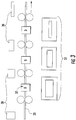
FIG. 3 is a schematic illustration of a method of manufacturing the motor winding. - Referring to
FIG. 1 , a portion of a rotary electric machine, such as amotor 10, is illustrated. The embodiments described herein may benefit numerous types of rotary electric machines. In some embodiments, the machine is a battery driven motor, with a low number of turns per coil, high power and low voltage. This type of motor has challenges with conventional manufacturing methods which result in high noise and/or low efficiency. One problem driving this issue is that most motor slots are inherently trapezoidal and most conductors are either circular or rectangular, for example. Therefore, the result is a low motor slot fill where much of the slot area is unused. - The
motor 10 includes astator assembly 12 made up of astator 14 and a plurality of windings generally designated withnumeral 16. Thestator 14 includes a plurality ofteeth 18 and a plurality ofslots 20 defined between respectivelyadjacent teeth 18. In the illustrated embodiment, each of the plurality ofslots 20 includes a pair ofwinding segments winding segments slot 20 and each represents an electrical conductor. Various contemplated electrically conductive materials may be used to form wires of thewinding segments - The
winding segments segments slot 20. For copper wire, the conductors are enameled. In the case of aluminum wire, the conductors may be enameled or oxidized. Optionally, the aluminum wire may be coated in copper to improve its conductivity, which is done prior to enameling. - The
winding segments slot 20, completely all or substantially all of the cross-section of the slot 20 (i.e., in the plane shown inFIGS. 1 and 2 ) is filled. By increasing the extent to which theslots 20 are filled with thewinding segments - Typical stator slot and winding cross-sectional shapes are not conducive to obtaining a high slot fill. This is due to the slot being trapezoidal, for example, while windings are circular or rectangular, thereby resulting in much of the slot are being unused. The embodiments of the
winding segments slot 20. The term "constant" used herein refers to thewinding segments - Various cross-sectional shapes of the
winding segments FIG. 1 ) and a trapezoidal cross-section (FIG. 2 ) are utilized. It is further contemplated that a combination of geometric shape segments may be employed. For example, a combination of rectangular and trapezoidal segments may be employed. Furthermore, any combination of rectangular, trapezoidal, circular and/or square segments may be utilized in some embodiments. - Regardless of the specific geometry, the cross-sectional area remains constant, but the shape changes to accommodate the contour of the surfaces that define the
slot 20 at different locations. As shown, in the illustrated trapezoidal slots, a wider winding segment is desirable proximate afirst end 26 of theslot 20, while a narrower winding segment is desirable proximate asecond end 28 of theslot 20. In particular, winding segment varies in portions along a length thereof. Each portion of the winding with a common cross-sectional geometric shape corresponds to a full turn of the winding around eachtooth 18. Therefore, the shape is the same at the same height on each side of thetooth 18. As the winding is wound around thetooth 18, the shape varies when going up or down (i.e., toward or away from theends winding segments slot 20. In some embodiments, the winding undergoes a number of full turns around the tooth ranging from 3 to 10. In such embodiments, the winding contains 3 to 10 winding segment portions with different geometric shapes, but with constant cross-sectional area. - Referring now to
FIG. 3 , a method of forming thewinding segments wire 30 is drawn through a series of dies 32 to create the variable cross-sectional shape while maintaining the constant cross-sectional area that was described above. The length of each turn of the windingsegments wire 30 is drawn through, the line is reversed to eject the wire to preserve the varied shape. To facilitate reversal, the dies 32 have a constant width and decreasing height as measured in a plane orthogonal to the direction of travel of the wire being drawn through the dies, with the width of thewire 30 being less than the width of the dies 32. Once thewire 30 is ejected from the dies 32, it is insulated in the manner described in detail above. - The winding
segments teeth 18 in a typical manner to dispose them in theslots 20. Prior to winding the final half turn, the winding segment is simultaneously energized and tensioned. Energizing the coil heats the metal to make it softer. When the winding segment is tensioned, the conductor pulls tight against thetooth 18. This improves the heat transfer between the coil and the tooth and improves the slot fill. Optionally, if self-bonding insulation is employed, this operation can solidify the tooth/coil assembly. - Advantageously, higher motor slot fill is achieved. This translates into better motor efficiency, motor cost reduction, or a combination of these two advantages.
- While the disclosure has been described in detail in connection with only a limited number of embodiments, it should be readily understood that the disclosure is not limited to such disclosed embodiments. Rather, the disclosure can be modified to incorporate any number of variations, alterations, substitutions or equivalent arrangements not heretofore described, but which are commensurate with the spirit and scope of the disclosure. Additionally, while various embodiments of the disclosure have been described, it is to be understood that aspects of the disclosure may include only some of the described embodiments. Accordingly, the disclosure is not to be seen as limited by the foregoing description, but is only limited by the scope of the appended claims.
Claims (15)
- A winding assembly for a rotary electric machine (10) comprising:a stator (14);a plurality of radially extending teeth (18) defining a plurality of slots (20) therebetween; anda winding segment (22, 24) disposed within each of the slots (20), the winding segment (22, 24) having a constant cross-sectional area along an entire length thereof and a cross-sectional geometric shape that varies at each turn along a height of the teeth (18).
- The winding assembly of claim 1, wherein the winding segment (22, 24) comprises a rectangular cross-sectional geometric shape.
- The winding assembly of claim 1, wherein the winding segment (22, 24) comprises a trapezoidal cross-sectional geometric shape.
- The winding assembly of claim 1, wherein the winding segment (22, 24) comprises a combination of trapezoidal and rectangular cross-sectional geometric shape portions.
- The winding assembly of any of the preceding claims, wherein the winding segment (22, 24) comprises a wire (30) surrounded by an insulating layer, the wire (30) comprising copper.
- The winding assembly of any of claims 1-4, wherein the winding segment (22, 24) comprises a wire (30) surrounded by an insulating layer, the wire comprising aluminum.
- The winding assembly of claim 5 or 6, wherein the insulating layer is enameled to the wire (30).
- The winding assembly of claim 5 or 6, wherein the insulating layer is oxidized to the wire (30).
- The winding assembly of any of the preceding claims, wherein the rotary electric machine (10) is a battery powered motor.
- A method of manufacturing motor windings comprising drawing a wire (30) through a plurality of dies (32), the plurality of dies (32) varying in at least two dimensions to form the wire to be of a constant cross-sectional area along an entire length thereof and a varying cross-sectional geometric shape.
- The method of claim 10, wherein the plurality of dies (32) have a constant width and a decreasing height as measured in a plane orthogonal to the direction of travel of the wire being drawn through the dies (32).
- The method of claim 10 or 11, further comprising reversing the direction of travel of the wire (30) to eject the wire from the dies (32).
- The method of any of claims 10-12, further comprising insulating the wire (30) by enameling the wire that is formed of copper.
- The method of any of claims 10-12, further comprising insulating the wire (30) by oxidizing the wire that is formed of aluminum.
- The method of any of claims 10-14, further comprising:winding the motor winding around a plurality of teeth (18) of a stator (14) to dispose the motor winding within a slot (20) of the stator (14) until a final half turn of the motor winding is required; andsimultaneously energizing the motor winding and tensioning the motor winding prior to winding the motor winding the final half turn.
Applications Claiming Priority (1)
| Application Number | Priority Date | Filing Date | Title |
|---|---|---|---|
| US15/228,306 US20180041082A1 (en) | 2016-08-04 | 2016-08-04 | Winding assembly for rotary electric machine and method of manufacturing |
Publications (3)
| Publication Number | Publication Date |
|---|---|
| EP3285367A2 true EP3285367A2 (en) | 2018-02-21 |
| EP3285367A3 EP3285367A3 (en) | 2018-03-07 |
| EP3285367B1 EP3285367B1 (en) | 2019-06-19 |
Family
ID=59522998
Family Applications (1)
| Application Number | Title | Priority Date | Filing Date |
|---|---|---|---|
| EP17184704.9A Active EP3285367B1 (en) | 2016-08-04 | 2017-08-03 | Winding assembly for rotary electric machine and method of manufacturing |
Country Status (3)
| Country | Link |
|---|---|
| US (1) | US20180041082A1 (en) |
| EP (1) | EP3285367B1 (en) |
| CN (1) | CN107689698A (en) |
Families Citing this family (1)
| Publication number | Priority date | Publication date | Assignee | Title |
|---|---|---|---|---|
| CN111641302B (en) * | 2020-05-19 | 2022-08-05 | 台州市金宇机电有限公司 | Winding method of motor stator for electric vehicle |
Family Cites Families (10)
| Publication number | Priority date | Publication date | Assignee | Title |
|---|---|---|---|---|
| BE514194A (en) * | ||||
| US3407472A (en) * | 1966-07-28 | 1968-10-29 | Gen Electric | Apparatus for developing electrical coils in inductive devices |
| JP2001178051A (en) * | 1999-12-10 | 2001-06-29 | Toyota Motor Corp | Concentrated winding coil and method for manufacturing and motor |
| US20110144841A1 (en) * | 2009-12-16 | 2011-06-16 | Murray Ruben | Electronic bike integrated supplemental motor system |
| EP2362526B1 (en) * | 2010-02-26 | 2014-04-09 | Siemens Aktiengesellschaft | Method for manufacturing a stator for an energy converting apparatus |
| CN102668335A (en) * | 2010-10-15 | 2012-09-12 | 丰田自动车株式会社 | Conductive wire for motor, and coil for motor |
| CN102039324B (en) * | 2010-10-21 | 2013-04-17 | 西北工业大学 | Device for preparing ultra-fine grain copper-aluminum wire with variable passage and preparation method |
| JP5737273B2 (en) * | 2012-11-15 | 2015-06-17 | 株式会社デンソー | Stator winding and method for manufacturing stator winding |
| TWI517524B (en) * | 2014-07-01 | 2016-01-11 | Victory Ind Corp | Alternator stator and stator winding |
| DE102014222376A1 (en) * | 2014-11-03 | 2016-05-04 | Bayerische Motoren Werke Aktiengesellschaft | Stator winding for an electric machine, electric machine with the stator winding, and method for its production |
-
2016
- 2016-08-04 US US15/228,306 patent/US20180041082A1/en not_active Abandoned
-
2017
- 2017-08-03 CN CN201710658451.8A patent/CN107689698A/en active Pending
- 2017-08-03 EP EP17184704.9A patent/EP3285367B1/en active Active
Non-Patent Citations (1)
| Title |
|---|
| None |
Also Published As
| Publication number | Publication date |
|---|---|
| US20180041082A1 (en) | 2018-02-08 |
| EP3285367B1 (en) | 2019-06-19 |
| EP3285367A3 (en) | 2018-03-07 |
| CN107689698A (en) | 2018-02-13 |
Similar Documents
| Publication | Publication Date | Title |
|---|---|---|
| EP2983274B1 (en) | Strand cross section variation for increasing fill factor in electric machine winding slots | |
| JP5692247B2 (en) | Collective conductor for motor winding | |
| KR102024972B1 (en) | Stator | |
| US10128706B2 (en) | Coil with twisted wires and stator assembly of a rotary electric machine | |
| JP5774082B2 (en) | Rotating electric machine | |
| CN109075624B (en) | Common laminated component for accommodating multiple conductor geometries in an electrical machine | |
| CN102904361A (en) | Field coil for an electric machine | |
| US11581773B2 (en) | Flat-angled coil having three-dimensional shape for maximizing space factor and electric motor comprising same | |
| CN101151782A (en) | Multipolar, linear or rotating synchronous direct drive motor | |
| US20210218294A1 (en) | Stator for a rotating electrical machine | |
| US6798105B1 (en) | Electrical machine with a winding | |
| CN108323222B (en) | Coil and stator assembly for rotary electric machine | |
| EP3285367B1 (en) | Winding assembly for rotary electric machine and method of manufacturing | |
| JP2015065787A (en) | Rotary electric machine | |
| CN106100189A (en) | Automotive dynamoelectric machine | |
| US20150155749A1 (en) | Method of manufacturing a laminated winding and a laminated winding | |
| CN112583165B (en) | Motor stator winding and stator and motor using same | |
| WO2021236567A8 (en) | Modulated litz wire construction for high power-density motors | |
| EP2892133B1 (en) | High slip variable frequency induction motors | |
| KR20210041027A (en) | Shaped stator winding for switched reluctance machines and manufacturing method thereof | |
| JP2013172486A (en) | Rotary electric machine | |
| CN112703663B (en) | Tooth coil and method for producing a tooth coil | |
| Blunder | STRATIFIED HAIPIN CONDUCTORS FOR REDUCTION OF EDDY CURRENTS | |
| CN113595288B (en) | Variable cross-section low-loss self-cooling runway type winding of permanent magnet motor | |
| CN211629951U (en) | Coil element structure of motor flat enameled wire winding |
Legal Events
| Date | Code | Title | Description |
|---|---|---|---|
| PUAI | Public reference made under article 153(3) epc to a published international application that has entered the european phase |
Free format text: ORIGINAL CODE: 0009012 |
|
| STAA | Information on the status of an ep patent application or granted ep patent |
Free format text: STATUS: THE APPLICATION HAS BEEN PUBLISHED |
|
| PUAL | Search report despatched |
Free format text: ORIGINAL CODE: 0009013 |
|
| AK | Designated contracting states |
Kind code of ref document: A2 Designated state(s): AL AT BE BG CH CY CZ DE DK EE ES FI FR GB GR HR HU IE IS IT LI LT LU LV MC MK MT NL NO PL PT RO RS SE SI SK SM TR |
|
| AX | Request for extension of the european patent |
Extension state: BA ME |
|
| AK | Designated contracting states |
Kind code of ref document: A3 Designated state(s): AL AT BE BG CH CY CZ DE DK EE ES FI FR GB GR HR HU IE IS IT LI LT LU LV MC MK MT NL NO PL PT RO RS SE SI SK SM TR |
|
| AX | Request for extension of the european patent |
Extension state: BA ME |
|
| RIC1 | Information provided on ipc code assigned before grant |
Ipc: B21C 1/18 20060101ALI20180130BHEP Ipc: H02K 3/12 20060101AFI20180130BHEP Ipc: H02K 15/00 20060101ALI20180130BHEP Ipc: B21C 1/00 20060101ALI20180130BHEP Ipc: B21C 3/04 20060101ALI20180130BHEP |
|
| STAA | Information on the status of an ep patent application or granted ep patent |
Free format text: STATUS: REQUEST FOR EXAMINATION WAS MADE |
|
| 17P | Request for examination filed |
Effective date: 20180905 |
|
| RBV | Designated contracting states (corrected) |
Designated state(s): AL AT BE BG CH CY CZ DE DK EE ES FI FR GB GR HR HU IE IS IT LI LT LU LV MC MK MT NL NO PL PT RO RS SE SI SK SM TR |
|
| GRAP | Despatch of communication of intention to grant a patent |
Free format text: ORIGINAL CODE: EPIDOSNIGR1 |
|
| STAA | Information on the status of an ep patent application or granted ep patent |
Free format text: STATUS: GRANT OF PATENT IS INTENDED |
|
| INTG | Intention to grant announced |
Effective date: 20190204 |
|
| GRAS | Grant fee paid |
Free format text: ORIGINAL CODE: EPIDOSNIGR3 |
|
| GRAA | (expected) grant |
Free format text: ORIGINAL CODE: 0009210 |
|
| STAA | Information on the status of an ep patent application or granted ep patent |
Free format text: STATUS: THE PATENT HAS BEEN GRANTED |
|
| AK | Designated contracting states |
Kind code of ref document: B1 Designated state(s): AL AT BE BG CH CY CZ DE DK EE ES FI FR GB GR HR HU IE IS IT LI LT LU LV MC MK MT NL NO PL PT RO RS SE SI SK SM TR |
|
| REG | Reference to a national code |
Ref country code: GB Ref legal event code: FG4D |
|
| REG | Reference to a national code |
Ref country code: CH Ref legal event code: EP |
|
| REG | Reference to a national code |
Ref country code: IE Ref legal event code: FG4D |
|
| REG | Reference to a national code |
Ref country code: DE Ref legal event code: R096 Ref document number: 602017004600 Country of ref document: DE |
|
| REG | Reference to a national code |
Ref country code: AT Ref legal event code: REF Ref document number: 1146738 Country of ref document: AT Kind code of ref document: T Effective date: 20190715 |
|
| REG | Reference to a national code |
Ref country code: NL Ref legal event code: MP Effective date: 20190619 |
|
| PG25 | Lapsed in a contracting state [announced via postgrant information from national office to epo] |
Ref country code: HR Free format text: LAPSE BECAUSE OF FAILURE TO SUBMIT A TRANSLATION OF THE DESCRIPTION OR TO PAY THE FEE WITHIN THE PRESCRIBED TIME-LIMIT Effective date: 20190619 Ref country code: LT Free format text: LAPSE BECAUSE OF FAILURE TO SUBMIT A TRANSLATION OF THE DESCRIPTION OR TO PAY THE FEE WITHIN THE PRESCRIBED TIME-LIMIT Effective date: 20190619 Ref country code: FI Free format text: LAPSE BECAUSE OF FAILURE TO SUBMIT A TRANSLATION OF THE DESCRIPTION OR TO PAY THE FEE WITHIN THE PRESCRIBED TIME-LIMIT Effective date: 20190619 Ref country code: NO Free format text: LAPSE BECAUSE OF FAILURE TO SUBMIT A TRANSLATION OF THE DESCRIPTION OR TO PAY THE FEE WITHIN THE PRESCRIBED TIME-LIMIT Effective date: 20190919 Ref country code: SE Free format text: LAPSE BECAUSE OF FAILURE TO SUBMIT A TRANSLATION OF THE DESCRIPTION OR TO PAY THE FEE WITHIN THE PRESCRIBED TIME-LIMIT Effective date: 20190619 Ref country code: AL Free format text: LAPSE BECAUSE OF FAILURE TO SUBMIT A TRANSLATION OF THE DESCRIPTION OR TO PAY THE FEE WITHIN THE PRESCRIBED TIME-LIMIT Effective date: 20190619 |
|
| REG | Reference to a national code |
Ref country code: LT Ref legal event code: MG4D |
|
| PG25 | Lapsed in a contracting state [announced via postgrant information from national office to epo] |
Ref country code: BG Free format text: LAPSE BECAUSE OF FAILURE TO SUBMIT A TRANSLATION OF THE DESCRIPTION OR TO PAY THE FEE WITHIN THE PRESCRIBED TIME-LIMIT Effective date: 20190919 Ref country code: LV Free format text: LAPSE BECAUSE OF FAILURE TO SUBMIT A TRANSLATION OF THE DESCRIPTION OR TO PAY THE FEE WITHIN THE PRESCRIBED TIME-LIMIT Effective date: 20190619 Ref country code: RS Free format text: LAPSE BECAUSE OF FAILURE TO SUBMIT A TRANSLATION OF THE DESCRIPTION OR TO PAY THE FEE WITHIN THE PRESCRIBED TIME-LIMIT Effective date: 20190619 Ref country code: GR Free format text: LAPSE BECAUSE OF FAILURE TO SUBMIT A TRANSLATION OF THE DESCRIPTION OR TO PAY THE FEE WITHIN THE PRESCRIBED TIME-LIMIT Effective date: 20190920 |
|
| REG | Reference to a national code |
Ref country code: AT Ref legal event code: MK05 Ref document number: 1146738 Country of ref document: AT Kind code of ref document: T Effective date: 20190619 |
|
| PG25 | Lapsed in a contracting state [announced via postgrant information from national office to epo] |
Ref country code: PT Free format text: LAPSE BECAUSE OF FAILURE TO SUBMIT A TRANSLATION OF THE DESCRIPTION OR TO PAY THE FEE WITHIN THE PRESCRIBED TIME-LIMIT Effective date: 20191021 Ref country code: EE Free format text: LAPSE BECAUSE OF FAILURE TO SUBMIT A TRANSLATION OF THE DESCRIPTION OR TO PAY THE FEE WITHIN THE PRESCRIBED TIME-LIMIT Effective date: 20190619 Ref country code: SK Free format text: LAPSE BECAUSE OF FAILURE TO SUBMIT A TRANSLATION OF THE DESCRIPTION OR TO PAY THE FEE WITHIN THE PRESCRIBED TIME-LIMIT Effective date: 20190619 Ref country code: RO Free format text: LAPSE BECAUSE OF FAILURE TO SUBMIT A TRANSLATION OF THE DESCRIPTION OR TO PAY THE FEE WITHIN THE PRESCRIBED TIME-LIMIT Effective date: 20190619 Ref country code: NL Free format text: LAPSE BECAUSE OF FAILURE TO SUBMIT A TRANSLATION OF THE DESCRIPTION OR TO PAY THE FEE WITHIN THE PRESCRIBED TIME-LIMIT Effective date: 20190619 Ref country code: CZ Free format text: LAPSE BECAUSE OF FAILURE TO SUBMIT A TRANSLATION OF THE DESCRIPTION OR TO PAY THE FEE WITHIN THE PRESCRIBED TIME-LIMIT Effective date: 20190619 Ref country code: AT Free format text: LAPSE BECAUSE OF FAILURE TO SUBMIT A TRANSLATION OF THE DESCRIPTION OR TO PAY THE FEE WITHIN THE PRESCRIBED TIME-LIMIT Effective date: 20190619 |
|
| PG25 | Lapsed in a contracting state [announced via postgrant information from national office to epo] |
Ref country code: IS Free format text: LAPSE BECAUSE OF FAILURE TO SUBMIT A TRANSLATION OF THE DESCRIPTION OR TO PAY THE FEE WITHIN THE PRESCRIBED TIME-LIMIT Effective date: 20191019 Ref country code: SM Free format text: LAPSE BECAUSE OF FAILURE TO SUBMIT A TRANSLATION OF THE DESCRIPTION OR TO PAY THE FEE WITHIN THE PRESCRIBED TIME-LIMIT Effective date: 20190619 Ref country code: ES Free format text: LAPSE BECAUSE OF FAILURE TO SUBMIT A TRANSLATION OF THE DESCRIPTION OR TO PAY THE FEE WITHIN THE PRESCRIBED TIME-LIMIT Effective date: 20190619 Ref country code: IT Free format text: LAPSE BECAUSE OF FAILURE TO SUBMIT A TRANSLATION OF THE DESCRIPTION OR TO PAY THE FEE WITHIN THE PRESCRIBED TIME-LIMIT Effective date: 20190619 |
|
| PG25 | Lapsed in a contracting state [announced via postgrant information from national office to epo] |
Ref country code: TR Free format text: LAPSE BECAUSE OF FAILURE TO SUBMIT A TRANSLATION OF THE DESCRIPTION OR TO PAY THE FEE WITHIN THE PRESCRIBED TIME-LIMIT Effective date: 20190619 |
|
| PG25 | Lapsed in a contracting state [announced via postgrant information from national office to epo] |
Ref country code: DK Free format text: LAPSE BECAUSE OF FAILURE TO SUBMIT A TRANSLATION OF THE DESCRIPTION OR TO PAY THE FEE WITHIN THE PRESCRIBED TIME-LIMIT Effective date: 20190619 Ref country code: PL Free format text: LAPSE BECAUSE OF FAILURE TO SUBMIT A TRANSLATION OF THE DESCRIPTION OR TO PAY THE FEE WITHIN THE PRESCRIBED TIME-LIMIT Effective date: 20190619 |
|
| PG25 | Lapsed in a contracting state [announced via postgrant information from national office to epo] |
Ref country code: IS Free format text: LAPSE BECAUSE OF FAILURE TO SUBMIT A TRANSLATION OF THE DESCRIPTION OR TO PAY THE FEE WITHIN THE PRESCRIBED TIME-LIMIT Effective date: 20200224 Ref country code: MC Free format text: LAPSE BECAUSE OF FAILURE TO SUBMIT A TRANSLATION OF THE DESCRIPTION OR TO PAY THE FEE WITHIN THE PRESCRIBED TIME-LIMIT Effective date: 20190619 Ref country code: LU Free format text: LAPSE BECAUSE OF NON-PAYMENT OF DUE FEES Effective date: 20190803 |
|
| REG | Reference to a national code |
Ref country code: BE Ref legal event code: MM Effective date: 20190831 |
|
| REG | Reference to a national code |
Ref country code: DE Ref legal event code: R097 Ref document number: 602017004600 Country of ref document: DE |
|
| PLBE | No opposition filed within time limit |
Free format text: ORIGINAL CODE: 0009261 |
|
| STAA | Information on the status of an ep patent application or granted ep patent |
Free format text: STATUS: NO OPPOSITION FILED WITHIN TIME LIMIT |
|
| PG2D | Information on lapse in contracting state deleted |
Ref country code: IS |
|
| PG25 | Lapsed in a contracting state [announced via postgrant information from national office to epo] |
Ref country code: IE Free format text: LAPSE BECAUSE OF NON-PAYMENT OF DUE FEES Effective date: 20190803 |
|
| 26N | No opposition filed |
Effective date: 20200603 |
|
| PG25 | Lapsed in a contracting state [announced via postgrant information from national office to epo] |
Ref country code: BE Free format text: LAPSE BECAUSE OF NON-PAYMENT OF DUE FEES Effective date: 20190831 Ref country code: SI Free format text: LAPSE BECAUSE OF FAILURE TO SUBMIT A TRANSLATION OF THE DESCRIPTION OR TO PAY THE FEE WITHIN THE PRESCRIBED TIME-LIMIT Effective date: 20190619 |
|
| REG | Reference to a national code |
Ref country code: CH Ref legal event code: PL |
|
| PG25 | Lapsed in a contracting state [announced via postgrant information from national office to epo] |
Ref country code: CH Free format text: LAPSE BECAUSE OF NON-PAYMENT OF DUE FEES Effective date: 20200831 Ref country code: LI Free format text: LAPSE BECAUSE OF NON-PAYMENT OF DUE FEES Effective date: 20200831 |
|
| PG25 | Lapsed in a contracting state [announced via postgrant information from national office to epo] |
Ref country code: CY Free format text: LAPSE BECAUSE OF FAILURE TO SUBMIT A TRANSLATION OF THE DESCRIPTION OR TO PAY THE FEE WITHIN THE PRESCRIBED TIME-LIMIT Effective date: 20190619 |
|
| PG25 | Lapsed in a contracting state [announced via postgrant information from national office to epo] |
Ref country code: MT Free format text: LAPSE BECAUSE OF FAILURE TO SUBMIT A TRANSLATION OF THE DESCRIPTION OR TO PAY THE FEE WITHIN THE PRESCRIBED TIME-LIMIT Effective date: 20190619 Ref country code: HU Free format text: LAPSE BECAUSE OF FAILURE TO SUBMIT A TRANSLATION OF THE DESCRIPTION OR TO PAY THE FEE WITHIN THE PRESCRIBED TIME-LIMIT; INVALID AB INITIO Effective date: 20170803 |
|
| GBPC | Gb: european patent ceased through non-payment of renewal fee |
Effective date: 20210803 |
|
| PG25 | Lapsed in a contracting state [announced via postgrant information from national office to epo] |
Ref country code: MK Free format text: LAPSE BECAUSE OF FAILURE TO SUBMIT A TRANSLATION OF THE DESCRIPTION OR TO PAY THE FEE WITHIN THE PRESCRIBED TIME-LIMIT Effective date: 20190619 |
|
| PG25 | Lapsed in a contracting state [announced via postgrant information from national office to epo] |
Ref country code: GB Free format text: LAPSE BECAUSE OF NON-PAYMENT OF DUE FEES Effective date: 20210803 |
|
| PGFP | Annual fee paid to national office [announced via postgrant information from national office to epo] |
Ref country code: FR Payment date: 20230720 Year of fee payment: 7 Ref country code: DE Payment date: 20230720 Year of fee payment: 7 |