EP3285002A1 - Lighting device for vehicle and lighting tool for vehicle - Google Patents
Lighting device for vehicle and lighting tool for vehicle Download PDFInfo
- Publication number
- EP3285002A1 EP3285002A1 EP17185674.3A EP17185674A EP3285002A1 EP 3285002 A1 EP3285002 A1 EP 3285002A1 EP 17185674 A EP17185674 A EP 17185674A EP 3285002 A1 EP3285002 A1 EP 3285002A1
- Authority
- EP
- European Patent Office
- Prior art keywords
- heat radiating
- face
- vehicle
- flange
- protrusion
- Prior art date
- Legal status (The legal status is an assumption and is not a legal conclusion. Google has not performed a legal analysis and makes no representation as to the accuracy of the status listed.)
- Withdrawn
Links
Images


Classifications
-
- F—MECHANICAL ENGINEERING; LIGHTING; HEATING; WEAPONS; BLASTING
- F21—LIGHTING
- F21S—NON-PORTABLE LIGHTING DEVICES; SYSTEMS THEREOF; VEHICLE LIGHTING DEVICES SPECIALLY ADAPTED FOR VEHICLE EXTERIORS
- F21S43/00—Signalling devices specially adapted for vehicle exteriors, e.g. brake lamps, direction indicator lights or reversing lights
- F21S43/10—Signalling devices specially adapted for vehicle exteriors, e.g. brake lamps, direction indicator lights or reversing lights characterised by the light source
- F21S43/19—Attachment of light sources or lamp holders
- F21S43/195—Details of lamp holders, terminals or connectors
-
- F—MECHANICAL ENGINEERING; LIGHTING; HEATING; WEAPONS; BLASTING
- F21—LIGHTING
- F21S—NON-PORTABLE LIGHTING DEVICES; SYSTEMS THEREOF; VEHICLE LIGHTING DEVICES SPECIALLY ADAPTED FOR VEHICLE EXTERIORS
- F21S43/00—Signalling devices specially adapted for vehicle exteriors, e.g. brake lamps, direction indicator lights or reversing lights
- F21S43/10—Signalling devices specially adapted for vehicle exteriors, e.g. brake lamps, direction indicator lights or reversing lights characterised by the light source
- F21S43/13—Signalling devices specially adapted for vehicle exteriors, e.g. brake lamps, direction indicator lights or reversing lights characterised by the light source characterised by the type of light source
- F21S43/14—Light emitting diodes [LED]
-
- F—MECHANICAL ENGINEERING; LIGHTING; HEATING; WEAPONS; BLASTING
- F21—LIGHTING
- F21S—NON-PORTABLE LIGHTING DEVICES; SYSTEMS THEREOF; VEHICLE LIGHTING DEVICES SPECIALLY ADAPTED FOR VEHICLE EXTERIORS
- F21S45/00—Arrangements within vehicle lighting devices specially adapted for vehicle exteriors, for purposes other than emission or distribution of light
- F21S45/10—Protection of lighting devices
-
- F—MECHANICAL ENGINEERING; LIGHTING; HEATING; WEAPONS; BLASTING
- F21—LIGHTING
- F21S—NON-PORTABLE LIGHTING DEVICES; SYSTEMS THEREOF; VEHICLE LIGHTING DEVICES SPECIALLY ADAPTED FOR VEHICLE EXTERIORS
- F21S45/00—Arrangements within vehicle lighting devices specially adapted for vehicle exteriors, for purposes other than emission or distribution of light
- F21S45/40—Cooling of lighting devices
- F21S45/47—Passive cooling, e.g. using fins, thermal conductive elements or openings
-
- F—MECHANICAL ENGINEERING; LIGHTING; HEATING; WEAPONS; BLASTING
- F21—LIGHTING
- F21V—FUNCTIONAL FEATURES OR DETAILS OF LIGHTING DEVICES OR SYSTEMS THEREOF; STRUCTURAL COMBINATIONS OF LIGHTING DEVICES WITH OTHER ARTICLES, NOT OTHERWISE PROVIDED FOR
- F21V29/00—Protecting lighting devices from thermal damage; Cooling or heating arrangements specially adapted for lighting devices or systems
- F21V29/50—Cooling arrangements
- F21V29/70—Cooling arrangements characterised by passive heat-dissipating elements, e.g. heat-sinks
- F21V29/74—Cooling arrangements characterised by passive heat-dissipating elements, e.g. heat-sinks with fins or blades
- F21V29/76—Cooling arrangements characterised by passive heat-dissipating elements, e.g. heat-sinks with fins or blades with essentially identical parallel planar fins or blades, e.g. with comb-like cross-section
-
- F—MECHANICAL ENGINEERING; LIGHTING; HEATING; WEAPONS; BLASTING
- F21—LIGHTING
- F21V—FUNCTIONAL FEATURES OR DETAILS OF LIGHTING DEVICES OR SYSTEMS THEREOF; STRUCTURAL COMBINATIONS OF LIGHTING DEVICES WITH OTHER ARTICLES, NOT OTHERWISE PROVIDED FOR
- F21V29/00—Protecting lighting devices from thermal damage; Cooling or heating arrangements specially adapted for lighting devices or systems
- F21V29/50—Cooling arrangements
- F21V29/70—Cooling arrangements characterised by passive heat-dissipating elements, e.g. heat-sinks
- F21V29/83—Cooling arrangements characterised by passive heat-dissipating elements, e.g. heat-sinks the elements having apertures, ducts or channels, e.g. heat radiation holes
-
- F—MECHANICAL ENGINEERING; LIGHTING; HEATING; WEAPONS; BLASTING
- F21—LIGHTING
- F21S—NON-PORTABLE LIGHTING DEVICES; SYSTEMS THEREOF; VEHICLE LIGHTING DEVICES SPECIALLY ADAPTED FOR VEHICLE EXTERIORS
- F21S41/00—Illuminating devices specially adapted for vehicle exteriors, e.g. headlamps
- F21S41/10—Illuminating devices specially adapted for vehicle exteriors, e.g. headlamps characterised by the light source
- F21S41/14—Illuminating devices specially adapted for vehicle exteriors, e.g. headlamps characterised by the light source characterised by the type of light source
- F21S41/141—Light emitting diodes [LED]
- F21S41/143—Light emitting diodes [LED] the main emission direction of the LED being parallel to the optical axis of the illuminating device
-
- F—MECHANICAL ENGINEERING; LIGHTING; HEATING; WEAPONS; BLASTING
- F21—LIGHTING
- F21S—NON-PORTABLE LIGHTING DEVICES; SYSTEMS THEREOF; VEHICLE LIGHTING DEVICES SPECIALLY ADAPTED FOR VEHICLE EXTERIORS
- F21S41/00—Illuminating devices specially adapted for vehicle exteriors, e.g. headlamps
- F21S41/10—Illuminating devices specially adapted for vehicle exteriors, e.g. headlamps characterised by the light source
- F21S41/19—Attachment of light sources or lamp holders
- F21S41/192—Details of lamp holders, terminals or connectors
-
- F—MECHANICAL ENGINEERING; LIGHTING; HEATING; WEAPONS; BLASTING
- F21—LIGHTING
- F21S—NON-PORTABLE LIGHTING DEVICES; SYSTEMS THEREOF; VEHICLE LIGHTING DEVICES SPECIALLY ADAPTED FOR VEHICLE EXTERIORS
- F21S41/00—Illuminating devices specially adapted for vehicle exteriors, e.g. headlamps
- F21S41/10—Illuminating devices specially adapted for vehicle exteriors, e.g. headlamps characterised by the light source
- F21S41/19—Attachment of light sources or lamp holders
- F21S41/194—Bayonet attachments
-
- F—MECHANICAL ENGINEERING; LIGHTING; HEATING; WEAPONS; BLASTING
- F21—LIGHTING
- F21Y—INDEXING SCHEME ASSOCIATED WITH SUBCLASSES F21K, F21L, F21S and F21V, RELATING TO THE FORM OR THE KIND OF THE LIGHT SOURCES OR OF THE COLOUR OF THE LIGHT EMITTED
- F21Y2115/00—Light-generating elements of semiconductor light sources
- F21Y2115/10—Light-emitting diodes [LED]
-
- H—ELECTRICITY
- H05—ELECTRIC TECHNIQUES NOT OTHERWISE PROVIDED FOR
- H05B—ELECTRIC HEATING; ELECTRIC LIGHT SOURCES NOT OTHERWISE PROVIDED FOR; CIRCUIT ARRANGEMENTS FOR ELECTRIC LIGHT SOURCES, IN GENERAL
- H05B45/00—Circuit arrangements for operating light-emitting diodes [LED]
Definitions
- Embodiments described herein relate generally to a lighting device for vehicle, and a lighting tool for vehicle.
- a lighting device for vehicle which includes a socket, and a light emitting module which is provided on one end face of the socket, and includes a light emitting diode (LED).
- LED light emitting diode
- Heat generated in the light emitting diode is mainly radiated to the outside through the socket.
- the heat radiating fin is provided on a side of the socket opposite to a side on which the light emitting module is provided.
- the lighting device for vehicle when the lighting device for vehicle is mounted on a lighting tool for vehicle, an end portion of the socket on the side on which the light emitting module is provided is inserted into a hole provided in the lighting tool for vehicle, the lighting device for vehicle is rotated, and is held in the lighting tool for vehicle.
- a mounting method is referred to as twist-lock.
- the number of heat radiating fins provided in a predetermined region is increased, by making a thickness of the heat radiating fin small.
- a worker grips the heat radiating fin when mounting the lighting device for vehicle there is a concern that the thin plate-shaped heat radiating fin may be damaged.
- a socket formed of a high heat conductive resin is proposed in order to make the lighting device for vehicle lightweight.
- intensity of a high heat conductive resin into which filler is mixed decreases. For this reason, when adopting a socket formed of a high heat conductive resin, damage of the heat radiating fin more easily occurs when a worker grips the heat radiating fin.
- a lighting device for vehicle includes a plate-shaped flange; a placing portion which is provided on a first face of the flange; a light emitting module which is provided at an end face of the placing portion, and includes a light emitting element; a plurality of heat radiating fins which are formed in a plate shape, and provided on a second face of the flange on a side opposite to the first face; a plurality of first protrusion portions which are provided on the second face of the flange in a line, in a direction intersecting a direction in which the plurality of heat radiating fins are aligned; and a second protrusion portion which is provided on the second face of the flange on a side opposite to the plurality of first protrusion portions, by interposing the plurality of heat radiating fins therebetween.
- a lighting device for vehicle 1 according to the embodiment can be provided in a vehicle, a railway vehicle, or the like, for example.
- the lighting device for vehicle 1 provided in a vehicle for example, it is possible to exemplify a device which is used in a front combination light (for example, light in which daytime running lamp (DRL), position lamp, turn signal lamp, and the like, are appropriately combined), a rear combination light (for example, stop lamp, tail lamp, turn signal lamp, back lamp, fog lamp, and the like, are appropriately combined), or the like.
- a use of the lighting device for vehicle 1 is not limited to these.
- FIG. 1 is a schematic perspective view for exemplifying the lighting device for vehicle 1 according to the embodiment.
- FIG. 2 is a perspective view in which the lighting device for vehicle 1 is viewed in a direction A in FIG. 1 .
- a socket 10 As illustrated in FIGS. 1 and 2 , a socket 10, a light emitting module 20, and a power feeding unit 30 are provided in the lighting device for vehicle 1.
- the socket 10 includes a receiving portion 10a and a heat radiating portion 10b.
- the receiving portion 10a includes a mounting unit 11, a bayonet 12, and an insulating portion 13.
- the mounting unit 11 is formed in a tubular shape.
- the mounting unit 11 can be set to a cylindrical shape, for example.
- the mounting unit 11 is provided on a face 14a (corresponding to an example of first face) of a flange 14 on a side opposite to a face 14b (corresponding to an example of second face) on which a heat radiating fin 16 is provided.
- the mounting unit 11 surrounds a placing portion 15.
- the bayonet 12 is provided on a side face of the mounting unit 11, and protrudes toward the outside of the lighting device for vehicle 1.
- the bayonet 12 faces the flange 14.
- a plurality of the bayonets 12 are provided.
- the bayonet 12 is used when attaching the lighting device for vehicle 1 to a lighting tool for vehicle 100 using twist-lock.
- the insulating portion 13 is provided inside the mounting unit 11.
- the receiving portion 10a can be formed by integrally molding the mounting unit 11, the bayonet 12, and the insulating portion 13, or can be formed by bonding thereof.
- the receiving portion 10a has a function of receiving the light emitting module 20, and a function of insulating a power feeding terminal 31. For this reason, it is preferable to form the mounting unit 11, the bayonet 12, and the insulating portion 13 using an insulating material.
- the insulating material can be set to an organic material such as a resin, for example, or an inorganic material such as ceramic (for example, aluminum oxide, or aluminum nitride), or the like.
- the heat radiating portion 10b includes the flange 14, the placing portion 15, the heat radiating fin 16, a terminal cover 17, a protrusion portion 18 (corresponding to an example of first protrusion portion), and a protrusion portion 19 (corresponding to an example of second protrusion portion).
- the flange 14 is formed in a plate shape.
- the flange 14 can be set to a flange formed in a disk shape, for example.
- An outer face of the flange 14 is located in the outside of the lighting device for vehicle 1, rather than the outer face of the bayonet 12.
- the placing portion 15 can be set to a columnar shape.
- the placing portion 15 is provided on the face 14a of the flange 14 on a side opposite to the face 14b on which the heat radiating fin 16 is provided.
- a recessed portion is provided on a side face of the placing portion 15.
- the insulating portion 13 is provided inside the recessed portion.
- the light emitting module 20 (substrate 21) including a light emitting element 22 is provided on an end face 15b of the placing portion 15.
- the heat radiating fin 16 is provided on the face 14b of the flange 14 on a side opposite to the face 14a.
- a plurality of the heat radiating fins 16 are provided.
- the plurality of heat radiating fins 16 can be provided so as to be parallel to each other.
- the heat radiating fin 16 can be set to a flat-plate shape.
- the terminal cover 17 has a function of protecting an end portion of the power feeding terminal 31, and a function of holding a connector 105.
- the terminal cover 17 is provided on the face 14b of the flange 14.
- the insulating portion 13 in which the power feeding terminal 31 is provided is provided at a position deviated from a peripheral edge of the flange 14 toward a center side. For this reason, the terminal cover 17 is also provided at a position deviated from the peripheral edge of the flange 14 toward the center side.
- the terminal cover 17 can be set to a rectangular tubular shape, for example.
- An end portion of the power feeding terminal 31 protrudes in the terminal cover 17.
- the connector 105 including a sealing member is mounted on the terminal cover 17.
- the protrusion portions 18 and 19 are provided on the face 14b of the flange 14. The protrusion portions 18 and 19 will be described later in detail.
- a heat radiating portion 10b can be formed by integrally molding the flange 14, the placing portion 15, the heat radiating fin 16, the terminal cover 17, and the protrusion portions 18 and 19, or it is also possible to bond these elements, by separately forming thereof.
- the heat radiating portion 10b has a function of placing the light emitting module 20, and a function of radiating heat generated in the light emitting module 20 to the outside. For this reason, it is preferable to form the heat radiating portion 10b using a material with high heat conductivity by taking the function of radiating heat into consideration. It is possible to set the material with high heat conductivity to, for example, metal such as aluminum, or an aluminum alloy, ceramic such as aluminum oxide, or aluminum nitride, a high heat conductive resin, or the like.
- the high heat conductive resin is obtained by mixing filler formed of aluminum oxide with high heat conductivity, or carbon into a resin such as polyethylene terephthalate (PET), or nylon, for example.
- the heat radiating portion 10b is bonded to the receiving portion 10a.
- the receiving portion 10a and the heat radiating portion 10b may be fitted to each other, may be bonded using an adhesive, or the like, may be integrally molded using an insert molding method, or, may be bonded using heat welding.
- the receiving portion 10a and the heat radiating portion 10b it is also possible to integrally mold the receiving portion 10a and the heat radiating portion 10b.
- the socket 10 receiving portion 10a and heat radiating portion 10b
- the socket 10 to be integrally molded using a high heat conductive resin, or the like.
- a lighting device for vehicle 1 which is lightweight, and of which a heat radiating property is improved.
- the light emitting module 20 is provided on the end face 15b of the placing portion 15.
- the light emitting module 20 includes the substrate 21, the light emitting element 22, a resistor 23, and a diode 24.
- the substrate 21 is provided on the face 15b of the placing portion 15.
- the substrate 21 is formed in a flat-plate shape.
- a wiring pattern 25 is provided on the surface of the substrate 21.
- a material or a structure of the substrate 21 is not particularly limited.
- the substrate 21 can be formed of an inorganic material such as ceramic (aluminum oxide, aluminum nitride, or the like), an organic material such as paper phenol, glass epoxy, or the like.
- the substrate 21 may be a substrate obtained by covering the surface of metal with an insulating material.
- the substrate 21 may be a single layer, or a multiple layer.
- the light emitting element 22 is provided on the substrate 21.
- the light emitting element 22 is electrically connected to the wiring pattern 25 which is provided on the surface of the substrate 21.
- the light emitting element 22 can be set to, for example, a light emitting diode, an organic light emitting diode, a laser diode, or the like.
- a form of the light emitting element 22 is not particularly limited.
- the light emitting element 22 can be set to a surface mounting-type light emitting element such as a plastic leaded chip carrier (PLCC) type.
- PLCC plastic leaded chip carrier
- the light emitting element 22 can also be set to a light emitting element including a lead wire of a cannonball type, or the like.
- the light emitting element 22 can also be set to an element which is mounted using a chip on board (COB).
- COB chip on board
- a chip-shaped light emitting element 22 wiring which electrically connects the light emitting element 22 and the wiring pattern 25
- a frame-shaped member which surrounds the light emitting element 22 and the wiring a sealing portion which is provided inside the frame-shaped member, and the like, can be provided on the substrate 21.
- a phosphor can be contained in the sealing portion.
- the phosphor can be set to a yttrium-aluminum-garnet-based phosphor (YAG), for example.
- YAG yttrium-aluminum-garnet-based phosphor
- a type of the phosphor is not particularly limited to the example, and can be appropriately changed so as to obtain a desired luminescent color according to a use of the lighting device for vehicle 1, or the like.
- the resistor 23 is provided on the substrate 21.
- the resistor 23 is electrically connected to the wiring pattern 25 provided on the surface of the substrate 21.
- the resistor 23 controls a current which flows in the light emitting element 22.
- the resistor 23 can be set to a surface mounting-type resistor, a resistor with a lead wire (metal oxide film resistor), a film-shaped resistor, or the like, which is formed, using a screen printing method, or the like.
- the resistor 23 exemplified in FIG. 1 is a film-shaped resistor.
- the number, a size, an arrangement, and the like, of the resistor 23 are not limited to the example, and can be appropriately changed according to the number, a specification, or the like, of the light emitting element 22.
- the diode 24 is provided on the substrate 21.
- the diode 24 is electrically connected to the wiring pattern 25 which is provided on the surface of the substrate 21.
- the diode 24 can be set to, for example, a surface mounting-type diode, a diode including a lead wire, or the like.
- the diode 24 exemplified in FIG. 1 is the surface mounting-type diode.
- the diode 24 can be provided on an input side of the light emitting module 20.
- the diode 24 is provided so as to cause a backward voltage is not applied to the light emitting element 22, and cause a pulse noise from a reverse direction is not applied to the light emitting element 22.
- a covering portion which covers the wiring pattern 25 or the film-shaped resistor.
- the covering portion can be set to a portion containing a glass material, for example.
- a pull-down resistor in order to detect disconnection of the light emitting element 22, prevent erroneous lighting, or the like.
- the power feeding unit 30 includes a plurality of power feeding terminals 31.
- the plurality of power feeding terminals 31 are provided inside the socket 10 (insulating portion 13).
- One end portion of the plurality of power feeding terminals 31 protrudes from an end face of the insulating portion 13 on a side opposite to the flange 14 side, and is electrically connected to the wiring pattern 25 provided on the substrate 21.
- the other end portion of the plurality of power feeding terminals 31 protrudes from the end face of the insulating portion 13 on the flange 14 side.
- the other end portion of the plurality of power feeding terminals 31 is exposed to the inside of the terminal cover 17.
- the number, a shape, or the like, of the power feeding terminal 31 is not limited to the example, and can be appropriately changed.
- the protrusion portion 18 can be set to a block shaped. By setting to the protrusion portion 18 formed in a block shape, rigidity of the protrusion portion 18 becomes higher than that of the heat radiating fin 16.
- the protrusion portion 18 protrudes from the face 14b of the flange 14.
- the protrusion portion 18 is provided in the vicinity of the peripheral edge of the flange 14.
- a plurality of the protrusion portions 18 can be provided. In a case of the example illustrated in FIG. 2 , two protrusion portions 18 are provided.
- the terminal cover 17 is provided between the plurality of protrusion portions 18.
- the plurality of protrusion portions 18 and the terminal cover 17 can be provided in a line, in a direction intersecting a direction in which the plurality of heat radiating fins 16 are aligned.
- a distance from the face 14b of the flange 14 to an end face of the protrusion portion 18 can be set to be approximately the same as the distance from the face 14b of the flange 14 to an end face of the terminal cover 17.
- the terminal cover 17 is provided between the plurality of protrusion portions 18.
- the plurality of protrusion portions 18 are provided in the vicinity of the peripheral edge of the flange 14, and the terminal cover 17 is provided at a position deviated from the peripheral edge of the flange 14 toward the center side. For this reason, it is possible to suppress an addition of an external force to the terminal cover 17.
- the protrusion portion 19 can be set to a block shape. By setting the protrusion portion 19 to the block shape, rigidity of the protrusion portion 19 increases compared to that of the heat radiating fin 16.
- the protrusion portion 19 protrudes from the face 14b of the flange 14.
- the protrusion portion 19 is provided in the vicinity of the peripheral edge of the flange 14.
- the protrusion portion 19 is provided on a side opposite to the plurality of protrusion portions 18 by interposing the plurality of heat radiating fins 16 therebetween. For this reason, both sides of the columns of the plurality of heat radiating fins 16 are surrounded with the plurality of protrusion portions 18 and the protrusion portion 19.
- a distance from the face 14b of the flange 14 to an end face of the protrusion portion 19 can be set to be approximately the same as a distance from the face 14b of the flange 14 to an end face of the plurality of heat radiating fins 16.
- a distance from the face 14b of the flange 14 to an end face of the protrusion portion 18 can be set to be approximately the same as a distance from the face 14b of the flange 14 to the end face of the plurality of heat radiating fins 16.
- the thickness of the plurality of heat radiating fins 16 when making the thickness of the plurality of heat radiating fins 16 small, it is possible to increase the number of heat radiating fins 16 which are provided in a predetermined region. When it is possible to increase the number of heat radiating fins 16, it is possible to make a heat radiating area large. For this reason, the thickness of the heat radiating fins 16 becomes small, in general. When making the thickness of the heat radiating fin 16 small, resistance of the heat radiating fin 16 to an external force decrease. In the lighting device for vehicle 1 according to the embodiment, both sides of the columns of the plurality of heat radiating fins 16 are surrounded with the plurality of protrusion portions 18 and the protrusion portion 19. For this reason, it is possible to suppress an addition of an external force to the plurality of heat radiating fins 16.
- the worker grips the heat radiating portion 10b of the lighting device for vehicle 1.
- the plurality of heat radiating fins 16 with low rigidity and the terminal cover 17 are provided in the heat radiating portion 10b.
- a high heat conductive resin containing filler has lower rigidity than that of a resin, metal, or the like. For this reason, when forming the heat radiating portion 10b using the high heat conductive resin, the plurality of heat radiating fins 16 and the terminal cover 17 are more easily damaged.
- the protrusion portions 18 and 19 can be set so as to have high rigidity compared to the plurality of heat radiating fins 16 and the terminal cover 17.
- the protrusion portions 18 and 19 are provided on the peripheral edge side of the flange 14, compared to the position in which the plurality of heat radiating fins 16 and the terminal cover 17 are provided. For this reason, when the lighting device for vehicle 1 is mounted on the lighting tool for vehicle 100 by a worker, the worker can easily grip the protrusion portion 18 and the protrusion portion 19 with high rigidity. As a result, when the lighting device for vehicle 1 is mounted on the lighting tool for vehicle 100 by the worker, it is possible to prevent the plurality of heat radiating fins 16 and the terminal cover 17 from being damaged.
- the protrusion portions 18 and 19 since there is a little restriction relating to an external dimension, a wall thickness, or the like, in the protrusion portions 18 and 19, it is possible to make a sectional area of the heat transfer path large. For this reason, it is possible to use the protrusion portions 18 and 19 as a heat radiating member. That is, it is possible for the protrusion portions 18 and 19 to have a function of not causing an external force to be added to the plurality of heat radiating fins 16 and the terminal cover 17, and a function of radiating heat together.
- the thickness of the heat radiating fin 16 is set to T (mm)
- the thickness of the protrusion portion 18 is set to T1 (mm)
- the thickness of the protrusion portion 19 is set to T2 (mm).
- T1 (mm) is an external dimension of the protrusion portion 18 in the thickness direction of the heat radiating fin 16.
- T2 (mm) is an external dimension of the protrusion portion 19 in the thickness direction of the heat radiating fin 16.
- T (mm), T1 (mm), and T2 (mm) satisfy the above described expressions, it is possible to prevent the protrusion portions 18 and 19 from being damaged when a worker grips the protrusion portions 18 and 19.
- a recessed portion 18a which is open to an end face of the protrusion portion 18 (corresponding to an example of first recessed portion), and a recessed portion 19a which is open to an end face of the protrusion portion 19 (corresponding to an example of second recessed portion).
- the recessed portions 18a and 19a are provided, it is possible to make the lighting device for vehicle lightweight.
- the number, the size, the depth, the arrangement, and the like, of the recessed portions 18a and 19a are not limited to the examples, and can be appropriately changed by taking the heat radiating property and the rigidity into consideration.
- FIGS. 3 to 5 are schematic perspective views which exemplify a heat radiating portion 10b1 according to another embodiment.
- the heat radiating portion 10b1 includes the flange 14, the placing portion 15, the terminal cover 17, and a protrusion portion 28.
- the heat radiating fin 16 is not provided in the heat radiating portion 10b1.
- the protrusion portion 28 is provided on the face 14b of the flange 14.
- the protrusion portion 28 can be set to a block shape.
- the protrusion portion 28 protrudes from the face 14b of the flange 14.
- An external dimension of the protrusion portion 28 can be set to be appropriately the same as that of the flange 14.
- a recessed portion 28a which is open to a side face is provided in the protrusion portion 28.
- the terminal cover 17 is provided inside the recessed portion 28a. That is, the terminal cover 17 with low rigidity is surrounded with the protrusion portion 28 with high rigidity.
- a distance from the face 14b of the flange 14 to the end face of the protrusion portion 28 can be set to be approximately the same as the distance from the face 14b of the flange 14 to the end face of the terminal cover 17. For this reason, it is possible to prevent an external force from being added to the terminal cover 17.
- the heat radiating portion 10b1 also can be formed by integrally molding the flange 14, the placing portion 15, the terminal cover 17, and the protrusion portion 28, or can be formed by separately forming and joining the elements.
- a material of the heat radiating portion 10b1 can be set to the same material of the heat radiating portion 10b.
- the protrusion portion 28 is provided, a worker can easily grip the protrusion portion 28 with high rigidity, when the lighting device for vehicle 1 is mounted on the lighting tool for vehicle 100 by the worker. As a result, it is possible to suppress damage of the terminal cover 17 when the lighting device for vehicle 1 is mounted on the lighting tool for vehicle 100 by the worker.
- the heat radiating fin 16 is not provided in the heat radiating portion 10b1.
- the heat radiating portion 10b1 when setting to the protrusion portion 28 formed in a block shape, it is possible to make the sectional area of the heat transfer path large.
- the heat radiating portion 10b1 when adopting the heat radiating portion 10b1 provided with the protrusion portion 28 formed in a block shape, it is possible to improve a heat radiating property compared to a heat radiating portion provided only with the plurality of heat radiating fins 16.
- the recessed portion 28b can be set to a through-hole.
- the recessed portion is set to the through-hole, it is possible to form an air current which flows inside the protrusion portion 28. For this reason, it is possible to improve a heat radiating property.
- the recessed portion 28b provided on the side face of the protrusion portion 28 can be set to a groove.
- the groove is provided on the side face of the protrusion portion 28, it is possible to form an air current which flows inside the groove. For this reason, it is possible to improve a heat radiating property.
- the recessed portion 28b When providing the recessed portion 28b, it is possible to make the lighting device for vehicle lightweight. In addition, it is possible to suppress a sink of a resin when enlarging the heat radiating area, or molding the protrusion portion 28.
- the number, a shape, a depth, an arrangement, or the like, of the recessed portion 28b is not limited to examples, and can be appropriately changed by taking a heat radiating property and rigidity into consideration.
- FIG. 6 is a schematic perspective view which exemplifies a heat radiating portion 10b2 according to another embodiment.
- the heat radiating portion 10b2 includes the flange 14, and a protrusion portion 38.
- the placing portion 15 is provided in the heat radiating portion 10b2.
- the heat radiating fin 16 is not provided in the heat radiating portion 10b2.
- the protrusion portion 38 is provided on the face 14b of the flange 14.
- the protrusion portion 38 can be set to a block shape.
- the protrusion portion 38 protrudes from the face 14b of the flange 14.
- the terminal cover 17 is formed integrally with the protrusion portion 38.
- a side face of the protrusion portion 38 is provided at a position in which the side face of the terminal cover 17 is provided.
- An external dimension of the protrusion portion 38 is set to be smaller than that of the flange 14.
- a distance from the face 14b of the flange 14 to the end face of the protrusion portion 38 can be set to be approximately the same as the distance from the face 14b of the flange 14 to the end face of the terminal cover 17. Since the terminal cover 17 with low rigidity and the protrusion portion 38 with high rigidity are integrally formed, it is possible to improve resistance to an external force at a portion corresponding to the terminal cover 17.
- heat radiating portion 10b2 it is also possible to form the heat radiating portion 10b2 by integrally molding the flange 14, the placing portion 15, and the protrusion portion 38, or by separately forming and joining the elements.
- a material of the heat radiating portion 10b2 can be set to be the same as that of the heat radiating portion 10b.
- the protrusion portion 38 Since the protrusion portion 38 is provided, a worker can easily grip the protrusion portion 38 with high rigidity, when mounting the lighting device for vehicle 1 on the lighting tool for vehicle 100. As a result, when the lighting device for vehicle 1 is mounted on the lighting tool for vehicle 100 by the worker, it is possible to suppress damage of a portion corresponding to the terminal cover 17.
- the heat radiating fin 16 is not provided in the heat radiating portion 10b1.
- the protrusion portion 38 formed in a block shape it is possible to make a sectional area of the heat transfer path large. For this reason, similarly to the above described protrusion portion 28, it is possible to improve a heat radiating property compared to a heat radiating portion provided only with the plurality of heat radiating fins 16.
- a recessed portion 38a which is open to an end face of the protrusion portion 38.
- the recessed portion 38a on a side face of the protrusion portion 38.
- the recessed portion 38a also can be set to a through-hole. When setting to the through-hole, it is possible to form an air current which flows inside the protrusion portion 38. For this reason, it is possible to improve a heat radiating property.
- the recessed portion 38a provided on the side face of the protrusion portion 38 also can be set to a groove. When the groove is provided on the side face of the protrusion portion 38, it is possible to form an air current which flows inside the groove. For this reason, it is possible to improve a heat radiating property.
- the recessed portion 38a When the recessed portion 38a is provided, it is possible to make the lighting device for vehicle lightweight. In addition, it is possible to suppress a sink of a resin when a heat radiating area is enlarged, or the protrusion portion 38 is molded.
- the number, a shape, a size, a depth, an arrangement, or the like, of the recessed portion 38a is not limited to examples, and can be appropriately changed by taking a heat radiating property and rigidity into consideration.
- a recessed portion 38b which is open to the side face and the end face of the protrusion portion 38.
- a plurality of the recessed portions 38b can be provided.
- the recessed portion 38b can be set so as to have a curved face.
- the shape of the recessed portion 38b can be set so as to be fitted to a finger of a person.
- the number, a shape, a size, an arrangement, and the like, of the recessed portion 38b are not limited to the examples, and can be appropriately changed.
- the heat radiating portion 10b2 in the embodiment it is possible to suppress damage of a heat radiating member, and to improve a heat radiating property.
- the lighting tool for vehicle 100 will be exemplified.
- the lighting tool for vehicle 100 is a front combination light provided in a vehicle
- the lighting tool for vehicle 100 is not limited to the front combination light provided in a vehicle.
- the lighting tool for vehicle 100 may be a lighting tool for vehicle which is provided in a vehicle, a railway vehicle, or the like.
- FIG. 7 is a schematic and partial sectional view for exemplifying the lighting tool for vehicle 100.
- the lighting device for vehicle 1 As illustrated in FIG. 7 , the lighting device for vehicle 1, a housing 101, a cover 102, an optical element portion 103, a sealing member 104, and the connector 105 are provided in the lighting tool for vehicle 100.
- the housing 101 holds the mounting unit 11.
- the housing 101 is formed in a box shape of which one end portion side is open.
- the housing 101 can be formed of a resin through which light is not transmitted, or the like, for example.
- An attaching hole 101a into which a portion in which the bayonet 12 of the mounting unit 11 is provided is inserted is provided on a base of the housing 101.
- a recessed portion into which the bayonet 12 provided in the mounting unit 11 is inserted is provided at the peripheral edge of the attaching hole 101a.
- a case in which the attaching hole 101a is directly provided in the housing 101 was exemplified; however, an attaching member including the attaching hole 101a may be provided in the housing 101.
- the cover 102 is provided so as to block the opening of the housing 101.
- the cover 102 can be formed of a light-transmitting resin, or the like. It is also possible to set the cover 102 to a cover with a function of lens, or the like.
- Light output from the lighting device for vehicle 1 is input to the optical element portion 103.
- the optical element portion 103 performs reflection, diffusion, light guiding, condensing, a formation of a predetermined light distributing pattern, or the like, of light output from the lighting device for vehicle 1.
- the optical element portion 103 exemplified in FIG. 7 is a reflector.
- the optical element portion 103 reflects light output from the lighting device for vehicle 1, and forms a predetermined light distributing pattern.
- the sealing member 104 is provided between the flange 14 and the housing 101.
- the sealing member 104 can be set to a member formed in an annular shape.
- the sealing member 104 can be formed of a material with elasticity such as rubber, or a silicone resin.
- the sealing member 104 When attaching the lighting device for vehicle 1 to the lighting tool for vehicle 100, the sealing member 104 is interposed between the flange 14 and the housing 101. For this reason, an inner space of the housing 101 is enclosed by the sealing member 104. In addition, the bayonet 12 is pushed to the housing 101 due to an elastic force of the sealing member 104. For this reason, it is possible to prevent the lighting device for vehicle 1 from escaping from the housing 101.
- the connector 105 is fitted to end portions of the plurality of power feeding terminals 31 which are exposed to the inside of the terminal cover 17.
- a power supply (not illustrated), or the like, is electrically connected to the connector 105. For this reason, the power supply (not illustrated), or the like, and the light emitting element 22 are electrically connected when the connector 105 is fitted to the end portion of the power feeding terminal 31.
- a sealing member (not illustrated) is provided in the connector 105.
- the sealing member is provided in order to prevent water from entering the inside of the terminal cover 17.
Landscapes
- Engineering & Computer Science (AREA)
- General Engineering & Computer Science (AREA)
- Physics & Mathematics (AREA)
- Microelectronics & Electronic Packaging (AREA)
- Optics & Photonics (AREA)
- Arrangement Of Elements, Cooling, Sealing, Or The Like Of Lighting Devices (AREA)
- Non-Portable Lighting Devices Or Systems Thereof (AREA)
Abstract
According to one embodiment, a lighting device for vehicle includes a plate-shaped flange; a placing portion which is provided on a first face of the flange; a light emitting module which is provided at an end face of the placing portion, and includes a light emitting element; a plurality of heat radiating fins which are formed in a plate shape, and are provided on a second face of the flange on a side opposite to the first face; a plurality of first protrusion portions which are provided on the second face of the flange in a line, in a direction intersecting a direction in which the plurality of heat radiating fins are aligned; and a second protrusion portion which is provided on the second face of the flange on a side opposite to the plurality of first protrusion portions, by interposing the plurality of heat radiating fins therebetween.
Description
- Embodiments described herein relate generally to a lighting device for vehicle, and a lighting tool for vehicle.
- There is a lighting device for vehicle which includes a socket, and a light emitting module which is provided on one end face of the socket, and includes a light emitting diode (LED).
- Heat generated in the light emitting diode is mainly radiated to the outside through the socket.
- For this reason, a plurality of thin plate-shaped heat radiating fins are provided in the socket.
- In addition, the heat radiating fin is provided on a side of the socket opposite to a side on which the light emitting module is provided.
- Here, when the lighting device for vehicle is mounted on a lighting tool for vehicle, an end portion of the socket on the side on which the light emitting module is provided is inserted into a hole provided in the lighting tool for vehicle, the lighting device for vehicle is rotated, and is held in the lighting tool for vehicle. Such a mounting method is referred to as twist-lock. When the lighting device for vehicle is mounted on the lighting tool for vehicle, a worker grips a side of the socket opposite to the side on which the light emitting module is provided. In this case, since the heat radiating fin is provided on the side of the socket opposite to the side on which the light emitting module is provided, the worker grips the heat radiating fin.
- Here, in the lighting device for vehicle, the number of heat radiating fins provided in a predetermined region is increased, by making a thickness of the heat radiating fin small. However, since a worker grips the heat radiating fin when mounting the lighting device for vehicle, there is a concern that the thin plate-shaped heat radiating fin may be damaged. In recent years, a socket formed of a high heat conductive resin is proposed in order to make the lighting device for vehicle lightweight. However, there is a problem in that intensity of a high heat conductive resin into which filler is mixed decreases. For this reason, when adopting a socket formed of a high heat conductive resin, damage of the heat radiating fin more easily occurs when a worker grips the heat radiating fin.
- Therefore, there is a desire for a development of a technology in which it is possible to suppress damage of a heat radiating member, and improve a heat radiating property.
-
-
FIG. 1 is a schematic perspective view which exemplifies a lighting device for vehicle according to an embodiment. -
FIG. 2 is a schematic view in which the lighting device for vehicle is viewed in a direction A inFIG. 1 . -
FIG. 3 is a schematic perspective view which exemplifies a heat radiating portion according to another embodiment. -
FIG. 4 is a schematic perspective view which exemplifies a heat radiating portion. -
FIG. 5 is a schematic perspective view which exemplifies a heat radiating portion. -
FIG. 6 is a schematic perspective view which exemplifies a heat radiating portion. -
FIG. 7 is a schematic and partial sectional view which exemplifies a lighting tool for vehicle. - A lighting device for vehicle according to one embodiment includes a plate-shaped flange; a placing portion which is provided on a first face of the flange; a light emitting module which is provided at an end face of the placing portion, and includes a light emitting element; a plurality of heat radiating fins which are formed in a plate shape, and provided on a second face of the flange on a side opposite to the first face; a plurality of first protrusion portions which are provided on the second face of the flange in a line, in a direction intersecting a direction in which the plurality of heat radiating fins are aligned; and a second protrusion portion which is provided on the second face of the flange on a side opposite to the plurality of first protrusion portions, by interposing the plurality of heat radiating fins therebetween.
- Hereinafter, the embodiment will be exemplified with reference to drawings. In addition, in each figure, the same reference numerals are attached to the same constituent elements, and detailed descriptions thereof will be appropriately omitted.
- A lighting device for
vehicle 1 according to the embodiment can be provided in a vehicle, a railway vehicle, or the like, for example. As the lighting device forvehicle 1 provided in a vehicle, for example, it is possible to exemplify a device which is used in a front combination light (for example, light in which daytime running lamp (DRL), position lamp, turn signal lamp, and the like, are appropriately combined), a rear combination light (for example, stop lamp, tail lamp, turn signal lamp, back lamp, fog lamp, and the like, are appropriately combined), or the like. However, a use of the lighting device forvehicle 1 is not limited to these. -
FIG. 1 is a schematic perspective view for exemplifying the lighting device forvehicle 1 according to the embodiment. -
FIG. 2 is a perspective view in which the lighting device forvehicle 1 is viewed in a direction A inFIG. 1 . - As illustrated in
FIGS. 1 and2 , asocket 10, alight emitting module 20, and apower feeding unit 30 are provided in the lighting device forvehicle 1. - The
socket 10 includes a receivingportion 10a and aheat radiating portion 10b. - The
receiving portion 10a includes amounting unit 11, abayonet 12, and aninsulating portion 13. - The
mounting unit 11 is formed in a tubular shape. Themounting unit 11 can be set to a cylindrical shape, for example. Themounting unit 11 is provided on aface 14a (corresponding to an example of first face) of aflange 14 on a side opposite to aface 14b (corresponding to an example of second face) on which aheat radiating fin 16 is provided. Themounting unit 11 surrounds a placingportion 15. - The
bayonet 12 is provided on a side face of themounting unit 11, and protrudes toward the outside of the lighting device forvehicle 1. Thebayonet 12 faces theflange 14. A plurality of thebayonets 12 are provided. Thebayonet 12 is used when attaching the lighting device forvehicle 1 to a lighting tool forvehicle 100 using twist-lock. - The
insulating portion 13 is provided inside themounting unit 11. - The
receiving portion 10a can be formed by integrally molding themounting unit 11, thebayonet 12, and theinsulating portion 13, or can be formed by bonding thereof. - The
receiving portion 10a has a function of receiving thelight emitting module 20, and a function of insulating apower feeding terminal 31. For this reason, it is preferable to form themounting unit 11, thebayonet 12, and theinsulating portion 13 using an insulating material. The insulating material can be set to an organic material such as a resin, for example, or an inorganic material such as ceramic (for example, aluminum oxide, or aluminum nitride), or the like. - The
heat radiating portion 10b includes theflange 14, the placingportion 15, theheat radiating fin 16, aterminal cover 17, a protrusion portion 18 (corresponding to an example of first protrusion portion), and a protrusion portion 19 (corresponding to an example of second protrusion portion). - The
flange 14 is formed in a plate shape. Theflange 14 can be set to a flange formed in a disk shape, for example. An outer face of theflange 14 is located in the outside of the lighting device forvehicle 1, rather than the outer face of thebayonet 12. - The placing
portion 15 can be set to a columnar shape. The placingportion 15 is provided on theface 14a of theflange 14 on a side opposite to theface 14b on which theheat radiating fin 16 is provided. A recessed portion is provided on a side face of the placingportion 15. Theinsulating portion 13 is provided inside the recessed portion. The light emitting module 20 (substrate 21) including alight emitting element 22 is provided on anend face 15b of the placingportion 15. - In addition, it is possible to provide a layer, or the like, formed of a metal substrate (not illustrated), heat conductive grease, or an adhesive between a face of the light emitting module 20 (substrate 21) on a side opposite to a side on which the
light emitting element 22 is provided and theend face 15b of the placingportion 15, in order to increase a heat radiating property. - The
heat radiating fin 16 is provided on theface 14b of theflange 14 on a side opposite to theface 14a. A plurality of theheat radiating fins 16 are provided. The plurality ofheat radiating fins 16 can be provided so as to be parallel to each other. Theheat radiating fin 16 can be set to a flat-plate shape. - The
terminal cover 17 has a function of protecting an end portion of thepower feeding terminal 31, and a function of holding a connector 105. Theterminal cover 17 is provided on theface 14b of theflange 14. The insulatingportion 13 in which thepower feeding terminal 31 is provided is provided at a position deviated from a peripheral edge of theflange 14 toward a center side. For this reason, theterminal cover 17 is also provided at a position deviated from the peripheral edge of theflange 14 toward the center side. Theterminal cover 17 can be set to a rectangular tubular shape, for example. An end portion of thepower feeding terminal 31 protrudes in theterminal cover 17. The connector 105 including a sealing member is mounted on theterminal cover 17. - The
protrusion portions face 14b of theflange 14. Theprotrusion portions - A
heat radiating portion 10b can be formed by integrally molding theflange 14, the placingportion 15, theheat radiating fin 16, theterminal cover 17, and theprotrusion portions - The
heat radiating portion 10b has a function of placing thelight emitting module 20, and a function of radiating heat generated in thelight emitting module 20 to the outside. For this reason, it is preferable to form theheat radiating portion 10b using a material with high heat conductivity by taking the function of radiating heat into consideration. It is possible to set the material with high heat conductivity to, for example, metal such as aluminum, or an aluminum alloy, ceramic such as aluminum oxide, or aluminum nitride, a high heat conductive resin, or the like. The high heat conductive resin is obtained by mixing filler formed of aluminum oxide with high heat conductivity, or carbon into a resin such as polyethylene terephthalate (PET), or nylon, for example. - The
heat radiating portion 10b is bonded to the receivingportion 10a. The receivingportion 10a and theheat radiating portion 10b may be fitted to each other, may be bonded using an adhesive, or the like, may be integrally molded using an insert molding method, or, may be bonded using heat welding. - In addition, it is also possible to integrally mold the receiving
portion 10a and theheat radiating portion 10b. For example, it is also possible to set the socket 10 (receivingportion 10a andheat radiating portion 10b) to be integrally molded using a high heat conductive resin, or the like. In this case, when forming at least any one of the receivingportion 10a and theheat radiating portion 10b using a high heat conductive resin, it is possible to obtain a lighting device forvehicle 1 which is lightweight, and of which a heat radiating property is improved. - The
light emitting module 20 is provided on theend face 15b of the placingportion 15. - The
light emitting module 20 includes thesubstrate 21, thelight emitting element 22, aresistor 23, and adiode 24. - The
substrate 21 is provided on theface 15b of the placingportion 15. Thesubstrate 21 is formed in a flat-plate shape. Awiring pattern 25 is provided on the surface of thesubstrate 21. A material or a structure of thesubstrate 21 is not particularly limited. For example, thesubstrate 21 can be formed of an inorganic material such as ceramic (aluminum oxide, aluminum nitride, or the like), an organic material such as paper phenol, glass epoxy, or the like. In addition, thesubstrate 21 may be a substrate obtained by covering the surface of metal with an insulating material. Thesubstrate 21 may be a single layer, or a multiple layer. - The
light emitting element 22 is provided on thesubstrate 21. Thelight emitting element 22 is electrically connected to thewiring pattern 25 which is provided on the surface of thesubstrate 21. Thelight emitting element 22 can be set to, for example, a light emitting diode, an organic light emitting diode, a laser diode, or the like. - A form of the
light emitting element 22 is not particularly limited. - The
light emitting element 22 can be set to a surface mounting-type light emitting element such as a plastic leaded chip carrier (PLCC) type. Thelight emitting element 22 exemplified inFIG. 1 is the surface mounting-type light emitting element. - The
light emitting element 22 can also be set to a light emitting element including a lead wire of a cannonball type, or the like. - The
light emitting element 22 can also be set to an element which is mounted using a chip on board (COB). When it is set to thelight emitting element 22 which is mounted, using the COB, a chip-shapedlight emitting element 22, wiring which electrically connects thelight emitting element 22 and thewiring pattern 25, a frame-shaped member which surrounds thelight emitting element 22 and the wiring, a sealing portion which is provided inside the frame-shaped member, and the like, can be provided on thesubstrate 21. In this case, a phosphor can be contained in the sealing portion. The phosphor can be set to a yttrium-aluminum-garnet-based phosphor (YAG), for example. However, a type of the phosphor is not particularly limited to the example, and can be appropriately changed so as to obtain a desired luminescent color according to a use of the lighting device forvehicle 1, or the like. - The
resistor 23 is provided on thesubstrate 21. Theresistor 23 is electrically connected to thewiring pattern 25 provided on the surface of thesubstrate 21. Theresistor 23 controls a current which flows in thelight emitting element 22. - Since there is unevenness in forward voltage characteristics of the
light emitting element 22, when setting an application voltage between an anode terminal and a ground terminal to be constant, there is unevenness in brightness (light flux, luminance, intensity of light, illuminance) of thelight emitting element 22. For this reason, it is set so that a value of current which flows in thelight emitting element 22 falls in a predetermined range using theresistor 23, in order for the brightness of thelight emitting element 22 to fall in a predetermined range. In this case, it can be set so that a value of current which flows in thelight emitting element 22 falls in a predetermined range, by changing a resistance value of theresistor 23. - The
resistor 23 can be set to a surface mounting-type resistor, a resistor with a lead wire (metal oxide film resistor), a film-shaped resistor, or the like, which is formed, using a screen printing method, or the like. Theresistor 23 exemplified inFIG. 1 is a film-shaped resistor. The number, a size, an arrangement, and the like, of theresistor 23 are not limited to the example, and can be appropriately changed according to the number, a specification, or the like, of thelight emitting element 22. - The
diode 24 is provided on thesubstrate 21. Thediode 24 is electrically connected to thewiring pattern 25 which is provided on the surface of thesubstrate 21. Thediode 24 can be set to, for example, a surface mounting-type diode, a diode including a lead wire, or the like. Thediode 24 exemplified inFIG. 1 is the surface mounting-type diode. Thediode 24 can be provided on an input side of thelight emitting module 20. Thediode 24 is provided so as to cause a backward voltage is not applied to thelight emitting element 22, and cause a pulse noise from a reverse direction is not applied to thelight emitting element 22. - In addition to that, it is also possible to provide a covering portion which covers the
wiring pattern 25 or the film-shaped resistor. The covering portion can be set to a portion containing a glass material, for example. In addition, it is also possible to provide a pull-down resistor in order to detect disconnection of thelight emitting element 22, prevent erroneous lighting, or the like. - The
power feeding unit 30 includes a plurality ofpower feeding terminals 31. The plurality ofpower feeding terminals 31 are provided inside the socket 10 (insulating portion 13). One end portion of the plurality ofpower feeding terminals 31 protrudes from an end face of the insulatingportion 13 on a side opposite to theflange 14 side, and is electrically connected to thewiring pattern 25 provided on thesubstrate 21. The other end portion of the plurality ofpower feeding terminals 31 protrudes from the end face of the insulatingportion 13 on theflange 14 side. The other end portion of the plurality ofpower feeding terminals 31 is exposed to the inside of theterminal cover 17. In addition, the number, a shape, or the like, of thepower feeding terminal 31 is not limited to the example, and can be appropriately changed. - Subsequently, the
protrusion portions - The
protrusion portion 18 can be set to a block shaped. By setting to theprotrusion portion 18 formed in a block shape, rigidity of theprotrusion portion 18 becomes higher than that of theheat radiating fin 16. Theprotrusion portion 18 protrudes from theface 14b of theflange 14. Theprotrusion portion 18 is provided in the vicinity of the peripheral edge of theflange 14. A plurality of theprotrusion portions 18 can be provided. In a case of the example illustrated inFIG. 2 , twoprotrusion portions 18 are provided. Theterminal cover 17 is provided between the plurality ofprotrusion portions 18. The plurality ofprotrusion portions 18 and theterminal cover 17 can be provided in a line, in a direction intersecting a direction in which the plurality ofheat radiating fins 16 are aligned. A distance from theface 14b of theflange 14 to an end face of theprotrusion portion 18 can be set to be approximately the same as the distance from theface 14b of theflange 14 to an end face of theterminal cover 17. - Here, since the connector 105 is mounted on the
terminal cover 17, it is difficult to make an external dimension (wall thickness dimension) of theterminal cover 17 large. For this reason, there is a case in which resistance of theterminal cover 17 to an external force decreases. In the lighting device forvehicle 1 according to the embodiment, theterminal cover 17 is provided between the plurality ofprotrusion portions 18. In addition, the plurality ofprotrusion portions 18 are provided in the vicinity of the peripheral edge of theflange 14, and theterminal cover 17 is provided at a position deviated from the peripheral edge of theflange 14 toward the center side. For this reason, it is possible to suppress an addition of an external force to theterminal cover 17. - The
protrusion portion 19 can be set to a block shape. By setting theprotrusion portion 19 to the block shape, rigidity of theprotrusion portion 19 increases compared to that of theheat radiating fin 16. Theprotrusion portion 19 protrudes from theface 14b of theflange 14. Theprotrusion portion 19 is provided in the vicinity of the peripheral edge of theflange 14. Theprotrusion portion 19 is provided on a side opposite to the plurality ofprotrusion portions 18 by interposing the plurality ofheat radiating fins 16 therebetween. For this reason, both sides of the columns of the plurality ofheat radiating fins 16 are surrounded with the plurality ofprotrusion portions 18 and theprotrusion portion 19. - A distance from the
face 14b of theflange 14 to an end face of theprotrusion portion 19 can be set to be approximately the same as a distance from theface 14b of theflange 14 to an end face of the plurality ofheat radiating fins 16. - In addition, a distance from the
face 14b of theflange 14 to an end face of theprotrusion portion 18 can be set to be approximately the same as a distance from theface 14b of theflange 14 to the end face of the plurality ofheat radiating fins 16. - Here, when making the thickness of the plurality of
heat radiating fins 16 small, it is possible to increase the number ofheat radiating fins 16 which are provided in a predetermined region. When it is possible to increase the number ofheat radiating fins 16, it is possible to make a heat radiating area large. For this reason, the thickness of theheat radiating fins 16 becomes small, in general. When making the thickness of theheat radiating fin 16 small, resistance of theheat radiating fin 16 to an external force decrease. In the lighting device forvehicle 1 according to the embodiment, both sides of the columns of the plurality ofheat radiating fins 16 are surrounded with the plurality ofprotrusion portions 18 and theprotrusion portion 19. For this reason, it is possible to suppress an addition of an external force to the plurality ofheat radiating fins 16. - As will be described later, when a worker mounts the lighting device for
vehicle 1 on the lighting tool forvehicle 100, the worker grips theheat radiating portion 10b of the lighting device forvehicle 1. In this case, the plurality ofheat radiating fins 16 with low rigidity and theterminal cover 17 are provided in theheat radiating portion 10b. For this reason, when the worker grips the plurality ofheat radiating fins 16 and theterminal cover 17, there is a concern that these may be damaged. In addition, a high heat conductive resin containing filler has lower rigidity than that of a resin, metal, or the like. For this reason, when forming theheat radiating portion 10b using the high heat conductive resin, the plurality ofheat radiating fins 16 and theterminal cover 17 are more easily damaged. - Meanwhile, there is a little restriction related to an external dimension, a wall thickness, or the like, in the
protrusion portions protrusion portions heat radiating fins 16 and theterminal cover 17. In addition, theprotrusion portions flange 14, compared to the position in which the plurality ofheat radiating fins 16 and theterminal cover 17 are provided. For this reason, when the lighting device forvehicle 1 is mounted on the lighting tool forvehicle 100 by a worker, the worker can easily grip theprotrusion portion 18 and theprotrusion portion 19 with high rigidity. As a result, when the lighting device forvehicle 1 is mounted on the lighting tool forvehicle 100 by the worker, it is possible to prevent the plurality ofheat radiating fins 16 and theterminal cover 17 from being damaged. - According to a knowledge obtained by inventors of the exemplary embodiment, it was clarified that it is not possible to improve a heat radiating property when the thickness of the plurality of
heat radiating fins 16 is set to be excessively small. As described above, it is considered that an improvement of heat radiating property can be obtained, by increasing the number ofheat radiating fins 16 which is provided in a predetermined region by making the thickness of theheat radiating fin 16 small, and increasing the heat radiating area. However, when making the thickness of theheat radiating fin 16 small, a sectional area of a heat transfer path becomes small, and heat resistance becomes large. When a heat resistance value becomes large, a transfer of heat to a tip end of the plurality ofheat radiating fins 16 is hindered. For this reason, when making the thickness of the plurality ofheat radiating fins 16 excessively small, it is not possible to obtain the improvement of the heat radiating property. - Meanwhile, since there is a little restriction relating to an external dimension, a wall thickness, or the like, in the
protrusion portions protrusion portions protrusion portions heat radiating fins 16 and theterminal cover 17, and a function of radiating heat together. - For this reason, it is possible to improve the heat radiating property when the
protrusion portions heat radiating fins 16 large to some extents, it is possible to further improve the heat radiating property. - According to a knowledge obtained by the inventors of the exemplary embodiment, it is preferable that the following expressions be satisfied, when the thickness of the
heat radiating fin 16 is set to T (mm), the thickness of theprotrusion portion 18 is set to T1 (mm), and the thickness of theprotrusion portion 19 is set to T2 (mm). In addition, T1 (mm) is an external dimension of theprotrusion portion 18 in the thickness direction of theheat radiating fin 16. T2 (mm) is an external dimension of theprotrusion portion 19 in the thickness direction of theheat radiating fin 16.
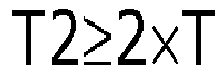
- When T (mm), T1 (mm), and T2 (mm) satisfy the above described expressions, it is possible to prevent the
protrusion portions protrusion portions protrusion portions protrusion portions - As illustrated in
FIG. 2 , it is also possible to provide a recessedportion 18a which is open to an end face of the protrusion portion 18 (corresponding to an example of first recessed portion), and a recessedportion 19a which is open to an end face of the protrusion portion 19 (corresponding to an example of second recessed portion). When the recessedportions protrusion portions portion 18a which is open to a side face of theprotrusion portion 18, and a recessedportion 19a which is open to a side face of theprotrusion portion 19. However, when setting to the recessedportion 18a which is open to the side faces of theprotrusion portion 18, and the recessedportion 19a which is open to the side faces of theprotrusion portion 19, there is a concern that the sectional area of the heat transfer path may become small. In addition, there is a concern that rigidity of theprotrusion portions portion 18a which is open to the end face of theprotrusion portion 18, and the recessedportion 19a which is open to the end face of theprotrusion portion 19. In addition, the number, the size, the depth, the arrangement, and the like, of the recessedportions -
FIGS. 3 to 5 are schematic perspective views which exemplify a heat radiating portion 10b1 according to another embodiment. - As illustrated in
FIGS. 3 to 5 , the heat radiating portion 10b1 includes theflange 14, the placingportion 15, theterminal cover 17, and aprotrusion portion 28. Theheat radiating fin 16 is not provided in the heat radiating portion 10b1. - The
protrusion portion 28 is provided on theface 14b of theflange 14. Theprotrusion portion 28 can be set to a block shape. Theprotrusion portion 28 protrudes from theface 14b of theflange 14. An external dimension of theprotrusion portion 28 can be set to be appropriately the same as that of theflange 14. A recessedportion 28a which is open to a side face is provided in theprotrusion portion 28. Theterminal cover 17 is provided inside the recessedportion 28a. That is, theterminal cover 17 with low rigidity is surrounded with theprotrusion portion 28 with high rigidity. A distance from theface 14b of theflange 14 to the end face of theprotrusion portion 28 can be set to be approximately the same as the distance from theface 14b of theflange 14 to the end face of theterminal cover 17. For this reason, it is possible to prevent an external force from being added to theterminal cover 17. - The heat radiating portion 10b1 also can be formed by integrally molding the
flange 14, the placingportion 15, theterminal cover 17, and theprotrusion portion 28, or can be formed by separately forming and joining the elements. In addition, a material of the heat radiating portion 10b1 can be set to the same material of theheat radiating portion 10b. - Since the
protrusion portion 28 is provided, a worker can easily grip theprotrusion portion 28 with high rigidity, when the lighting device forvehicle 1 is mounted on the lighting tool forvehicle 100 by the worker. As a result, it is possible to suppress damage of theterminal cover 17 when the lighting device forvehicle 1 is mounted on the lighting tool forvehicle 100 by the worker. - Here, the
heat radiating fin 16 is not provided in the heat radiating portion 10b1. However, when setting to theprotrusion portion 28 formed in a block shape, it is possible to make the sectional area of the heat transfer path large. According to a knowledge obtained by the inventors of the exemplary embodiment, when adopting the heat radiating portion 10b1 provided with theprotrusion portion 28 formed in a block shape, it is possible to improve a heat radiating property compared to a heat radiating portion provided only with the plurality ofheat radiating fins 16. - As illustrated in
FIG. 3 , it is also possible to provide a recessedportion 28b which is open to the end face of theprotrusion portion 28. - As illustrated in
FIG. 4 , it is also possible to provide the recessedportion 28b on the side face of theprotrusion portion 28. In this case, the recessedportion 28b can be set to a through-hole. When the recessed portion is set to the through-hole, it is possible to form an air current which flows inside theprotrusion portion 28. For this reason, it is possible to improve a heat radiating property. - As illustrated in
FIG. 5 , the recessedportion 28b provided on the side face of theprotrusion portion 28 can be set to a groove. When the groove is provided on the side face of theprotrusion portion 28, it is possible to form an air current which flows inside the groove. For this reason, it is possible to improve a heat radiating property. - When providing the recessed
portion 28b, it is possible to make the lighting device for vehicle lightweight. In addition, it is possible to suppress a sink of a resin when enlarging the heat radiating area, or molding theprotrusion portion 28. The number, a shape, a depth, an arrangement, or the like, of the recessedportion 28b is not limited to examples, and can be appropriately changed by taking a heat radiating property and rigidity into consideration. - When adopting the heat radiating portion 10b1 according to the embodiment, it is possible to suppress damage of a heat radiating member, and improve a heat radiating property.
-
FIG. 6 is a schematic perspective view which exemplifies a heat radiating portion 10b2 according to another embodiment. - As illustrated in
FIG. 6 , the heat radiating portion 10b2 includes theflange 14, and aprotrusion portion 38. In addition, similarly to the above describedheat radiating portion 10b, the placingportion 15 is provided in the heat radiating portion 10b2. Theheat radiating fin 16 is not provided in the heat radiating portion 10b2. - The
protrusion portion 38 is provided on theface 14b of theflange 14. Theprotrusion portion 38 can be set to a block shape. Theprotrusion portion 38 protrudes from theface 14b of theflange 14. Theterminal cover 17 is formed integrally with theprotrusion portion 38. For this reason, a side face of theprotrusion portion 38 is provided at a position in which the side face of theterminal cover 17 is provided. An external dimension of theprotrusion portion 38 is set to be smaller than that of theflange 14. In addition, a distance from theface 14b of theflange 14 to the end face of theprotrusion portion 38 can be set to be approximately the same as the distance from theface 14b of theflange 14 to the end face of theterminal cover 17. Since theterminal cover 17 with low rigidity and theprotrusion portion 38 with high rigidity are integrally formed, it is possible to improve resistance to an external force at a portion corresponding to theterminal cover 17. - It is also possible to form the heat radiating portion 10b2 by integrally molding the
flange 14, the placingportion 15, and theprotrusion portion 38, or by separately forming and joining the elements. A material of the heat radiating portion 10b2 can be set to be the same as that of theheat radiating portion 10b. - Since the
protrusion portion 38 is provided, a worker can easily grip theprotrusion portion 38 with high rigidity, when mounting the lighting device forvehicle 1 on the lighting tool forvehicle 100. As a result, when the lighting device forvehicle 1 is mounted on the lighting tool forvehicle 100 by the worker, it is possible to suppress damage of a portion corresponding to theterminal cover 17. - Here, the
heat radiating fin 16 is not provided in the heat radiating portion 10b1. However, when theprotrusion portion 38 formed in a block shape is adopted, it is possible to make a sectional area of the heat transfer path large. For this reason, similarly to the above describedprotrusion portion 28, it is possible to improve a heat radiating property compared to a heat radiating portion provided only with the plurality ofheat radiating fins 16. - In addition, it is also possible to provide a recessed
portion 38a which is open to an end face of theprotrusion portion 38. Similarly to the above described recessedportion 28b, it is also possible to provide the recessedportion 38a on a side face of theprotrusion portion 38. In this case, the recessedportion 38a also can be set to a through-hole. When setting to the through-hole, it is possible to form an air current which flows inside theprotrusion portion 38. For this reason, it is possible to improve a heat radiating property. In addition, the recessedportion 38a provided on the side face of theprotrusion portion 38 also can be set to a groove. When the groove is provided on the side face of theprotrusion portion 38, it is possible to form an air current which flows inside the groove. For this reason, it is possible to improve a heat radiating property. - When the recessed
portion 38a is provided, it is possible to make the lighting device for vehicle lightweight. In addition, it is possible to suppress a sink of a resin when a heat radiating area is enlarged, or theprotrusion portion 38 is molded. The number, a shape, a size, a depth, an arrangement, or the like, of the recessedportion 38a is not limited to examples, and can be appropriately changed by taking a heat radiating property and rigidity into consideration. - It is possible to provide a recessed
portion 38b which is open to the side face and the end face of theprotrusion portion 38. A plurality of the recessedportions 38b can be provided. The recessedportion 38b can be set so as to have a curved face. The shape of the recessedportion 38b can be set so as to be fitted to a finger of a person. When the plurality of recessedportions 38b are provided, it is easier for a worker to grip theprotrusion portion 38. In addition, it is possible to provide the recessedportion 38b also in the above describedprotrusion portions protrusion portion 28. The number, a shape, a size, an arrangement, and the like, of the recessedportion 38b are not limited to the examples, and can be appropriately changed. - According to the heat radiating portion 10b2 in the embodiment, it is possible to suppress damage of a heat radiating member, and to improve a heat radiating property.
- Subsequently, the lighting tool for
vehicle 100 will be exemplified. - Hereinafter, a case in which the lighting tool for
vehicle 100 is a front combination light provided in a vehicle will be described, as an example. However, the lighting tool forvehicle 100 is not limited to the front combination light provided in a vehicle. The lighting tool forvehicle 100 may be a lighting tool for vehicle which is provided in a vehicle, a railway vehicle, or the like. -
FIG. 7 is a schematic and partial sectional view for exemplifying the lighting tool forvehicle 100. - As illustrated in
FIG. 7 , the lighting device forvehicle 1, ahousing 101, acover 102, anoptical element portion 103, a sealingmember 104, and the connector 105 are provided in the lighting tool forvehicle 100. - The
housing 101 holds the mountingunit 11. Thehousing 101 is formed in a box shape of which one end portion side is open. Thehousing 101 can be formed of a resin through which light is not transmitted, or the like, for example. An attachinghole 101a into which a portion in which thebayonet 12 of the mountingunit 11 is provided is inserted is provided on a base of thehousing 101. A recessed portion into which thebayonet 12 provided in the mountingunit 11 is inserted is provided at the peripheral edge of the attachinghole 101a. A case in which the attachinghole 101a is directly provided in thehousing 101 was exemplified; however, an attaching member including the attachinghole 101a may be provided in thehousing 101. - When attaching the lighting device for
vehicle 1 to the lighting tool forvehicle 100, the portion in which thebayonet 12 of the mountingunit 11 is provided is inserted into the attachinghole 101a, and the lighting device forvehicle 1 is rotated. Then, thebayonet 12 is held in a joint portion provided at the peripheral edge of the attachinghole 101a. Such an attaching method is referred to as twist-lock. - The
cover 102 is provided so as to block the opening of thehousing 101. Thecover 102 can be formed of a light-transmitting resin, or the like. It is also possible to set thecover 102 to a cover with a function of lens, or the like. - Light output from the lighting device for
vehicle 1 is input to theoptical element portion 103. Theoptical element portion 103 performs reflection, diffusion, light guiding, condensing, a formation of a predetermined light distributing pattern, or the like, of light output from the lighting device forvehicle 1. - For example, the
optical element portion 103 exemplified inFIG. 7 is a reflector. In this case, theoptical element portion 103 reflects light output from the lighting device forvehicle 1, and forms a predetermined light distributing pattern. - The sealing
member 104 is provided between theflange 14 and thehousing 101. The sealingmember 104 can be set to a member formed in an annular shape. The sealingmember 104 can be formed of a material with elasticity such as rubber, or a silicone resin. - When attaching the lighting device for
vehicle 1 to the lighting tool forvehicle 100, the sealingmember 104 is interposed between theflange 14 and thehousing 101. For this reason, an inner space of thehousing 101 is enclosed by the sealingmember 104. In addition, thebayonet 12 is pushed to thehousing 101 due to an elastic force of the sealingmember 104. For this reason, it is possible to prevent the lighting device forvehicle 1 from escaping from thehousing 101. - The connector 105 is fitted to end portions of the plurality of
power feeding terminals 31 which are exposed to the inside of theterminal cover 17. A power supply (not illustrated), or the like, is electrically connected to the connector 105. For this reason, the power supply (not illustrated), or the like, and thelight emitting element 22 are electrically connected when the connector 105 is fitted to the end portion of thepower feeding terminal 31. - In addition, a sealing member (not illustrated) is provided in the connector 105. The sealing member is provided in order to prevent water from entering the inside of the
terminal cover 17. When the connector 105 including the sealing member is mounted on theterminal cover 17, the inside of theterminal cover 17 is enclosed so as to be watertight. - While certain embodiments have been described, these embodiments have been presented by way of example only, and are not intended to limit the scope of the inventions. Indeed, the novel embodiments described herein may be embodied in a variety of other forms; furthermore, various omissions, substitutions and changes in the form of the embodiments described herein may be made without departing from the spirit of the inventions. The accompanying claims and their equivalents are intended to cover such forms or modifications as would fall within the scope and spirit of the inventions. Moreover, above-mentioned embodiments can be combined mutually and can be carried out.
Claims (7)
- A lighting device for vehicle (1) comprising:a plate-shaped flange (14);a placing portion (15) which is provided on a first face (14a) of the flange (14);a light emitting module (20) which is provided at an end face (15b) of the placing portion (15), and includes a light emitting element (22);a plurality of heat radiating fins (16) which are formed in a plate shape, and provided on a second face (14b) of the flange (14) on a side opposite to the first face (14a);a plurality of first protrusion portions (18) which are provided on the second face (14b) of the flange (14) in a line, in a direction intersecting a direction in which the plurality of heat radiating fins (16) are aligned; anda second protrusion portion (19) which is provided on the second face (14b) of the flange (14) on a side opposite to the plurality of first protrusion portions (18), by interposing the plurality of heat radiating fins (16) therebetween.
- The device (1) according to claim 1,
wherein at least any one of the plurality of first protrusion portions (18) includes a first recessed portion (18a) which is open to an end face. - The device (1) according to claim 1 or 2,
wherein the second protrusion portion (19) includes a second recessed portion (19a) which is open to the end face. - The device (1) according to any one of claims 1 to 3,
wherein the plurality of first protrusion portions (18) are provided in vicinity of the peripheral edge of the flange (14). - The device (1) according to any one of claims 1 to 4,
wherein the second protrusion portion (19) is provided in the vicinity of the peripheral edge of the flange (14). - The device (1) according to any one of claims 1 to 5,
wherein the flange (14), the plurality of heat radiating fins (16), the plurality of first protrusion portions (18), and the second protrusion portion (19) include a high heat conductive resin. - A lighting tool for vehicle (100) comprising:the lighting device for vehicle (1) according to any one of claims 1 to 6; anda housing (101) to which the lighting device for vehicle is attached.
Applications Claiming Priority (1)
| Application Number | Priority Date | Filing Date | Title |
|---|---|---|---|
| JP2016161314A JP6722402B2 (en) | 2016-08-19 | 2016-08-19 | Vehicle lighting device and vehicle lamp |
Publications (1)
| Publication Number | Publication Date |
|---|---|
| EP3285002A1 true EP3285002A1 (en) | 2018-02-21 |
Family
ID=59581771
Family Applications (1)
| Application Number | Title | Priority Date | Filing Date |
|---|---|---|---|
| EP17185674.3A Withdrawn EP3285002A1 (en) | 2016-08-19 | 2017-08-10 | Lighting device for vehicle and lighting tool for vehicle |
Country Status (4)
| Country | Link |
|---|---|
| US (1) | US10309609B2 (en) |
| EP (1) | EP3285002A1 (en) |
| JP (1) | JP6722402B2 (en) |
| CN (1) | CN206958836U (en) |
Cited By (3)
| Publication number | Priority date | Publication date | Assignee | Title |
|---|---|---|---|---|
| EP3575678A1 (en) * | 2018-05-29 | 2019-12-04 | Toshiba Lighting & Technology Corporation | Vehicle luminaire and vehicle lamp device |
| FR3103536A1 (en) * | 2019-11-25 | 2021-05-28 | Psa Automobiles Sa | Motor vehicle headlight housing comprising a connector protection device |
| US20220381428A1 (en) * | 2021-05-25 | 2022-12-01 | Toshiba Lighting & Technology Corporation | Vehicle Luminaire and Vehicle Lamp |
Families Citing this family (9)
| Publication number | Priority date | Publication date | Assignee | Title |
|---|---|---|---|---|
| JP6724709B2 (en) * | 2016-10-13 | 2020-07-15 | 東芝ライテック株式会社 | Vehicle lighting device and vehicle lamp |
| EP3522682B1 (en) * | 2018-02-06 | 2020-07-29 | ZKW Group GmbH | Circuit arrangement, lighting device and vehicle headlight |
| JP7079654B2 (en) * | 2018-05-17 | 2022-06-02 | スタンレー電気株式会社 | Vehicle lighting |
| JP2020113506A (en) * | 2019-01-16 | 2020-07-27 | 東芝ライテック株式会社 | Vehicle lighting device and vehicle lamp |
| JP7585741B2 (en) * | 2020-11-26 | 2024-11-19 | 市光工業株式会社 | Vehicle lighting fixtures |
| CN215174775U (en) * | 2021-03-29 | 2021-12-14 | 欧司朗股份有限公司 | Lamp with a light source |
| KR102746036B1 (en) * | 2022-10-11 | 2024-12-23 | 주식회사 현대케피코 | Oxygen sensor to prevent heat damage |
| US20240240771A1 (en) * | 2023-01-17 | 2024-07-18 | Hopkins Manufacturing Corporation | Vehicle light bar with improved heat dissipation fins |
| CN120083937B (en) * | 2025-05-06 | 2025-08-29 | 浙江屹纬精密技术有限公司 | Automobile headlight lamp holder and manufacturing method |
Citations (7)
| Publication number | Priority date | Publication date | Assignee | Title |
|---|---|---|---|---|
| WO2008119392A1 (en) * | 2007-04-03 | 2008-10-09 | Osram Gesellschaft mit beschränkter Haftung | Semiconductor light module |
| JP2012119243A (en) * | 2010-12-03 | 2012-06-21 | Stanley Electric Co Ltd | Led standard module, and vehicular lamp having the same |
| WO2013153938A1 (en) * | 2012-04-11 | 2013-10-17 | 東芝ライテック株式会社 | Optical semiconductor light source and lighting apparatus for vehicle |
| JP2013247062A (en) * | 2012-05-29 | 2013-12-09 | Ichikoh Ind Ltd | Light source unit of semiconductor type light source for vehicle lamp and vehicle lamp |
| EP2899455A2 (en) * | 2014-01-28 | 2015-07-29 | Koito Manufacturing Co., Ltd. | Light source unit |
| JP2016106351A (en) * | 2015-07-24 | 2016-06-16 | 東芝ライテック株式会社 | Vehicular lighting device |
| JP2016106352A (en) * | 2015-09-17 | 2016-06-16 | 東芝ライテック株式会社 | Vehicular lighting device |
Family Cites Families (7)
| Publication number | Priority date | Publication date | Assignee | Title |
|---|---|---|---|---|
| DE102004062990A1 (en) * | 2004-12-22 | 2006-07-06 | Patent-Treuhand-Gesellschaft für elektrische Glühlampen mbH | Lighting device with at least one light emitting diode and vehicle headlights |
| US7905639B2 (en) * | 2008-05-28 | 2011-03-15 | Osram Sylvania Inc. | Side-loaded light emitting diode module for automotive rear combination lamps |
| JP5409217B2 (en) * | 2009-09-07 | 2014-02-05 | 株式会社小糸製作所 | Vehicle lighting |
| US8998458B2 (en) * | 2011-05-31 | 2015-04-07 | Sabic Global Technologies B.V. | LED plastic heat sink and method for making and using the same |
| US9091426B2 (en) * | 2012-03-29 | 2015-07-28 | Abl Ip Holding Llc | Light assembly |
| JP6171270B2 (en) | 2012-05-29 | 2017-08-02 | 市光工業株式会社 | Light source unit for semiconductor light source of vehicle lamp, method for manufacturing light source unit of semiconductor light source for vehicle lamp, and vehicle lamp |
| EP2857739B1 (en) | 2012-05-29 | 2020-04-08 | Ichikoh Industries, Ltd. | Vehicular lighting instrument semiconductor light source light source unit and vehicular lighting instrument |
-
2016
- 2016-08-19 JP JP2016161314A patent/JP6722402B2/en active Active
-
2017
- 2017-08-07 CN CN201720976040.9U patent/CN206958836U/en active Active
- 2017-08-09 US US15/672,985 patent/US10309609B2/en active Active
- 2017-08-10 EP EP17185674.3A patent/EP3285002A1/en not_active Withdrawn
Patent Citations (7)
| Publication number | Priority date | Publication date | Assignee | Title |
|---|---|---|---|---|
| WO2008119392A1 (en) * | 2007-04-03 | 2008-10-09 | Osram Gesellschaft mit beschränkter Haftung | Semiconductor light module |
| JP2012119243A (en) * | 2010-12-03 | 2012-06-21 | Stanley Electric Co Ltd | Led standard module, and vehicular lamp having the same |
| WO2013153938A1 (en) * | 2012-04-11 | 2013-10-17 | 東芝ライテック株式会社 | Optical semiconductor light source and lighting apparatus for vehicle |
| JP2013247062A (en) * | 2012-05-29 | 2013-12-09 | Ichikoh Ind Ltd | Light source unit of semiconductor type light source for vehicle lamp and vehicle lamp |
| EP2899455A2 (en) * | 2014-01-28 | 2015-07-29 | Koito Manufacturing Co., Ltd. | Light source unit |
| JP2016106351A (en) * | 2015-07-24 | 2016-06-16 | 東芝ライテック株式会社 | Vehicular lighting device |
| JP2016106352A (en) * | 2015-09-17 | 2016-06-16 | 東芝ライテック株式会社 | Vehicular lighting device |
Cited By (5)
| Publication number | Priority date | Publication date | Assignee | Title |
|---|---|---|---|---|
| EP3575678A1 (en) * | 2018-05-29 | 2019-12-04 | Toshiba Lighting & Technology Corporation | Vehicle luminaire and vehicle lamp device |
| US10591127B2 (en) | 2018-05-29 | 2020-03-17 | Toshiba Lighting & Technology Corporation | Vehicle luminaire and vehicle lamp device |
| FR3103536A1 (en) * | 2019-11-25 | 2021-05-28 | Psa Automobiles Sa | Motor vehicle headlight housing comprising a connector protection device |
| US20220381428A1 (en) * | 2021-05-25 | 2022-12-01 | Toshiba Lighting & Technology Corporation | Vehicle Luminaire and Vehicle Lamp |
| US11525566B1 (en) * | 2021-05-25 | 2022-12-13 | Toshiba Lighting & Technology Corporation | Vehicle luminaire and vehicle lamp |
Also Published As
| Publication number | Publication date |
|---|---|
| JP2018029037A (en) | 2018-02-22 |
| CN206958836U (en) | 2018-02-02 |
| JP6722402B2 (en) | 2020-07-15 |
| US10309609B2 (en) | 2019-06-04 |
| US20180051858A1 (en) | 2018-02-22 |
Similar Documents
| Publication | Publication Date | Title |
|---|---|---|
| US10309609B2 (en) | Lighting device for vehicle and lighting tool for vehicle | |
| US10203080B1 (en) | Lighting device for vehicles and lighting tool for vehicles | |
| US10903192B2 (en) | Vehicle luminaire and vehicle lamp | |
| US10371366B2 (en) | Lighting device for vehicle, manufacturing method of lighting device for vehicle, and lighting tool for vehicle | |
| US10591127B2 (en) | Vehicle luminaire and vehicle lamp device | |
| US11168863B2 (en) | Vehicular luminaire, vehicular lamp, and method for manufacturing vehicular luminaire | |
| US20220381428A1 (en) | Vehicle Luminaire and Vehicle Lamp | |
| US10654400B2 (en) | Lighting device for vehicles and lighting tool for vehicles | |
| US10781993B2 (en) | Vehicle luminaire and vehicle lamp device | |
| US20200355342A1 (en) | Vehicle Luminaire and Vehicle Lamp | |
| US11821603B1 (en) | Vehicle lighting device and vehicle lamp | |
| JP2021079899A (en) | Vehicular lighting device and vehicular lighting fixture | |
| US10907791B2 (en) | Vehicle luminaire and vehicle lamp | |
| US12055278B2 (en) | Vehicle lighting device and vehicle lamp | |
| JP2021168237A (en) | Vehicle lighting equipment and vehicle lighting equipment | |
| EP3829269B1 (en) | Vehicle luminaire and vehicle lamp | |
| JP2019220425A (en) | Vehicular lighting device and vehicular lighting fixture | |
| JP2020017350A (en) | Vehicle lighting device and vehicle lamp fitting | |
| JP7075050B2 (en) | Vehicle lighting equipment and vehicle lighting equipment | |
| JP2022074314A (en) | Vehicular illuminating device, and vehicular lighting fixture | |
| JP2023175148A (en) | Vehicle lighting equipment and vehicle lights | |
| JP2022191770A (en) | Vehicular illuminating device, and vehicular lighting fixture | |
| JP2023078614A (en) | Vehicle lighting device and vehicle lamp | |
| JP2021039937A (en) | Vehicle lighting equipment and vehicle lighting equipment | |
| JP2021028867A (en) | Vehicle lighting device and vehicle lighting fixture |
Legal Events
| Date | Code | Title | Description |
|---|---|---|---|
| PUAI | Public reference made under article 153(3) epc to a published international application that has entered the european phase |
Free format text: ORIGINAL CODE: 0009012 |
|
| STAA | Information on the status of an ep patent application or granted ep patent |
Free format text: STATUS: THE APPLICATION HAS BEEN PUBLISHED |
|
| AK | Designated contracting states |
Kind code of ref document: A1 Designated state(s): AL AT BE BG CH CY CZ DE DK EE ES FI FR GB GR HR HU IE IS IT LI LT LU LV MC MK MT NL NO PL PT RO RS SE SI SK SM TR |
|
| AX | Request for extension of the european patent |
Extension state: BA ME |
|
| STAA | Information on the status of an ep patent application or granted ep patent |
Free format text: STATUS: THE APPLICATION IS DEEMED TO BE WITHDRAWN |
|
| 18D | Application deemed to be withdrawn |
Effective date: 20180822 |