EP3284654A1 - Method for controlling autonomous valet system pathing for a motor vehicle - Google Patents
Method for controlling autonomous valet system pathing for a motor vehicle Download PDFInfo
- Publication number
- EP3284654A1 EP3284654A1 EP17184845.0A EP17184845A EP3284654A1 EP 3284654 A1 EP3284654 A1 EP 3284654A1 EP 17184845 A EP17184845 A EP 17184845A EP 3284654 A1 EP3284654 A1 EP 3284654A1
- Authority
- EP
- European Patent Office
- Prior art keywords
- parking
- path
- operative
- motor vehicle
- obstruction zone
- Prior art date
- Legal status (The legal status is an assumption and is not a legal conclusion. Google has not performed a legal analysis and makes no representation as to the accuracy of the status listed.)
- Withdrawn
Links
Images


Classifications
-
- G—PHYSICS
- G05—CONTROLLING; REGULATING
- G05D—SYSTEMS FOR CONTROLLING OR REGULATING NON-ELECTRIC VARIABLES
- G05D1/00—Control of position, course, altitude or attitude of land, water, air or space vehicles, e.g. using automatic pilots
- G05D1/02—Control of position or course in two dimensions
- G05D1/021—Control of position or course in two dimensions specially adapted to land vehicles
- G05D1/0231—Control of position or course in two dimensions specially adapted to land vehicles using optical position detecting means
- G05D1/0246—Control of position or course in two dimensions specially adapted to land vehicles using optical position detecting means using a video camera in combination with image processing means
-
- B—PERFORMING OPERATIONS; TRANSPORTING
- B60—VEHICLES IN GENERAL
- B60W—CONJOINT CONTROL OF VEHICLE SUB-UNITS OF DIFFERENT TYPE OR DIFFERENT FUNCTION; CONTROL SYSTEMS SPECIALLY ADAPTED FOR HYBRID VEHICLES; ROAD VEHICLE DRIVE CONTROL SYSTEMS FOR PURPOSES NOT RELATED TO THE CONTROL OF A PARTICULAR SUB-UNIT
- B60W30/00—Purposes of road vehicle drive control systems not related to the control of a particular sub-unit, e.g. of systems using conjoint control of vehicle sub-units
- B60W30/06—Automatic manoeuvring for parking
-
- B—PERFORMING OPERATIONS; TRANSPORTING
- B60—VEHICLES IN GENERAL
- B60W—CONJOINT CONTROL OF VEHICLE SUB-UNITS OF DIFFERENT TYPE OR DIFFERENT FUNCTION; CONTROL SYSTEMS SPECIALLY ADAPTED FOR HYBRID VEHICLES; ROAD VEHICLE DRIVE CONTROL SYSTEMS FOR PURPOSES NOT RELATED TO THE CONTROL OF A PARTICULAR SUB-UNIT
- B60W50/00—Details of control systems for road vehicle drive control not related to the control of a particular sub-unit, e.g. process diagnostic or vehicle driver interfaces
- B60W50/08—Interaction between the driver and the control system
- B60W50/082—Selecting or switching between different modes of propelling
-
- B—PERFORMING OPERATIONS; TRANSPORTING
- B62—LAND VEHICLES FOR TRAVELLING OTHERWISE THAN ON RAILS
- B62D—MOTOR VEHICLES; TRAILERS
- B62D15/00—Steering not otherwise provided for
- B62D15/02—Steering position indicators ; Steering position determination; Steering aids
- B62D15/027—Parking aids, e.g. instruction means
- B62D15/0285—Parking performed automatically
-
- G—PHYSICS
- G01—MEASURING; TESTING
- G01C—MEASURING DISTANCES, LEVELS OR BEARINGS; SURVEYING; NAVIGATION; GYROSCOPIC INSTRUMENTS; PHOTOGRAMMETRY OR VIDEOGRAMMETRY
- G01C21/00—Navigation; Navigational instruments not provided for in groups G01C1/00 - G01C19/00
- G01C21/26—Navigation; Navigational instruments not provided for in groups G01C1/00 - G01C19/00 specially adapted for navigation in a road network
- G01C21/34—Route searching; Route guidance
- G01C21/3407—Route searching; Route guidance specially adapted for specific applications
-
- G—PHYSICS
- G01—MEASURING; TESTING
- G01C—MEASURING DISTANCES, LEVELS OR BEARINGS; SURVEYING; NAVIGATION; GYROSCOPIC INSTRUMENTS; PHOTOGRAMMETRY OR VIDEOGRAMMETRY
- G01C21/00—Navigation; Navigational instruments not provided for in groups G01C1/00 - G01C19/00
- G01C21/26—Navigation; Navigational instruments not provided for in groups G01C1/00 - G01C19/00 specially adapted for navigation in a road network
- G01C21/34—Route searching; Route guidance
- G01C21/36—Input/output arrangements for on-board computers
- G01C21/3679—Retrieval, searching and output of POI information, e.g. hotels, restaurants, shops, filling stations, parking facilities
- G01C21/3685—Retrieval, searching and output of POI information, e.g. hotels, restaurants, shops, filling stations, parking facilities the POI's being parking facilities
-
- G—PHYSICS
- G05—CONTROLLING; REGULATING
- G05D—SYSTEMS FOR CONTROLLING OR REGULATING NON-ELECTRIC VARIABLES
- G05D1/00—Control of position, course, altitude or attitude of land, water, air or space vehicles, e.g. using automatic pilots
-
- G—PHYSICS
- G05—CONTROLLING; REGULATING
- G05D—SYSTEMS FOR CONTROLLING OR REGULATING NON-ELECTRIC VARIABLES
- G05D1/00—Control of position, course, altitude or attitude of land, water, air or space vehicles, e.g. using automatic pilots
- G05D1/02—Control of position or course in two dimensions
- G05D1/021—Control of position or course in two dimensions specially adapted to land vehicles
- G05D1/0257—Control of position or course in two dimensions specially adapted to land vehicles using a radar
-
- G—PHYSICS
- G05—CONTROLLING; REGULATING
- G05D—SYSTEMS FOR CONTROLLING OR REGULATING NON-ELECTRIC VARIABLES
- G05D1/00—Control of position, course, altitude or attitude of land, water, air or space vehicles, e.g. using automatic pilots
- G05D1/02—Control of position or course in two dimensions
- G05D1/021—Control of position or course in two dimensions specially adapted to land vehicles
- G05D1/0276—Control of position or course in two dimensions specially adapted to land vehicles using signals provided by a source external to the vehicle
- G05D1/0278—Control of position or course in two dimensions specially adapted to land vehicles using signals provided by a source external to the vehicle using satellite positioning signals, e.g. GPS
-
- G—PHYSICS
- G05—CONTROLLING; REGULATING
- G05D—SYSTEMS FOR CONTROLLING OR REGULATING NON-ELECTRIC VARIABLES
- G05D1/00—Control of position, course, altitude or attitude of land, water, air or space vehicles, e.g. using automatic pilots
- G05D1/02—Control of position or course in two dimensions
- G05D1/021—Control of position or course in two dimensions specially adapted to land vehicles
- G05D1/0276—Control of position or course in two dimensions specially adapted to land vehicles using signals provided by a source external to the vehicle
- G05D1/028—Control of position or course in two dimensions specially adapted to land vehicles using signals provided by a source external to the vehicle using a RF signal
- G05D1/0282—Control of position or course in two dimensions specially adapted to land vehicles using signals provided by a source external to the vehicle using a RF signal generated in a local control room
-
- G—PHYSICS
- G05—CONTROLLING; REGULATING
- G05D—SYSTEMS FOR CONTROLLING OR REGULATING NON-ELECTRIC VARIABLES
- G05D1/00—Control of position, course, altitude or attitude of land, water, air or space vehicles, e.g. using automatic pilots
- G05D1/02—Control of position or course in two dimensions
- G05D1/021—Control of position or course in two dimensions specially adapted to land vehicles
- G05D1/0276—Control of position or course in two dimensions specially adapted to land vehicles using signals provided by a source external to the vehicle
- G05D1/0285—Control of position or course in two dimensions specially adapted to land vehicles using signals provided by a source external to the vehicle using signals transmitted via a public communication network, e.g. GSM network
-
- G—PHYSICS
- G08—SIGNALLING
- G08G—TRAFFIC CONTROL SYSTEMS
- G08G1/00—Traffic control systems for road vehicles
- G08G1/14—Traffic control systems for road vehicles indicating individual free spaces in parking areas
- G08G1/141—Traffic control systems for road vehicles indicating individual free spaces in parking areas with means giving the indication of available parking spaces
- G08G1/143—Traffic control systems for road vehicles indicating individual free spaces in parking areas with means giving the indication of available parking spaces inside the vehicles
-
- G—PHYSICS
- G08—SIGNALLING
- G08G—TRAFFIC CONTROL SYSTEMS
- G08G1/00—Traffic control systems for road vehicles
- G08G1/14—Traffic control systems for road vehicles indicating individual free spaces in parking areas
- G08G1/141—Traffic control systems for road vehicles indicating individual free spaces in parking areas with means giving the indication of available parking spaces
- G08G1/144—Traffic control systems for road vehicles indicating individual free spaces in parking areas with means giving the indication of available parking spaces on portable or mobile units, e.g. personal digital assistant [PDA]
-
- G—PHYSICS
- G08—SIGNALLING
- G08G—TRAFFIC CONTROL SYSTEMS
- G08G1/00—Traffic control systems for road vehicles
- G08G1/14—Traffic control systems for road vehicles indicating individual free spaces in parking areas
- G08G1/145—Traffic control systems for road vehicles indicating individual free spaces in parking areas where the indication depends on the parking areas
- G08G1/146—Traffic control systems for road vehicles indicating individual free spaces in parking areas where the indication depends on the parking areas where the parking area is a limited parking space, e.g. parking garage, restricted space
-
- G—PHYSICS
- G08—SIGNALLING
- G08G—TRAFFIC CONTROL SYSTEMS
- G08G1/00—Traffic control systems for road vehicles
- G08G1/16—Anti-collision systems
- G08G1/168—Driving aids for parking, e.g. acoustic or visual feedback on parking space
-
- B—PERFORMING OPERATIONS; TRANSPORTING
- B60—VEHICLES IN GENERAL
- B60W—CONJOINT CONTROL OF VEHICLE SUB-UNITS OF DIFFERENT TYPE OR DIFFERENT FUNCTION; CONTROL SYSTEMS SPECIALLY ADAPTED FOR HYBRID VEHICLES; ROAD VEHICLE DRIVE CONTROL SYSTEMS FOR PURPOSES NOT RELATED TO THE CONTROL OF A PARTICULAR SUB-UNIT
- B60W2420/00—Indexing codes relating to the type of sensors based on the principle of their operation
- B60W2420/40—Photo, light or radio wave sensitive means, e.g. infrared sensors
- B60W2420/403—Image sensing, e.g. optical camera
-
- B—PERFORMING OPERATIONS; TRANSPORTING
- B60—VEHICLES IN GENERAL
- B60W—CONJOINT CONTROL OF VEHICLE SUB-UNITS OF DIFFERENT TYPE OR DIFFERENT FUNCTION; CONTROL SYSTEMS SPECIALLY ADAPTED FOR HYBRID VEHICLES; ROAD VEHICLE DRIVE CONTROL SYSTEMS FOR PURPOSES NOT RELATED TO THE CONTROL OF A PARTICULAR SUB-UNIT
- B60W2420/00—Indexing codes relating to the type of sensors based on the principle of their operation
- B60W2420/40—Photo, light or radio wave sensitive means, e.g. infrared sensors
- B60W2420/408—Radar; Laser, e.g. lidar
-
- B—PERFORMING OPERATIONS; TRANSPORTING
- B60—VEHICLES IN GENERAL
- B60W—CONJOINT CONTROL OF VEHICLE SUB-UNITS OF DIFFERENT TYPE OR DIFFERENT FUNCTION; CONTROL SYSTEMS SPECIALLY ADAPTED FOR HYBRID VEHICLES; ROAD VEHICLE DRIVE CONTROL SYSTEMS FOR PURPOSES NOT RELATED TO THE CONTROL OF A PARTICULAR SUB-UNIT
- B60W2554/00—Input parameters relating to objects
- B60W2554/20—Static objects
Definitions
- the invention relates generally to autonomous driver assistance systems for motor vehicles, and more particularly to a method of controlling a path of an autonomous driver assistance system for parking and un-parking or retrieving a motor vehicle.
- a method for autonomously parking or un-parking a motor vehicle includes receiving a map of a parking area having a first temporary obstruction zone, determining a starting location of the motor vehicle relative to the parking area, selecting a destination location within the parking area, setting the first temporary obstruction zone as operative or inoperative, generating a path from the starting location to the destination location, wherein the path does not enter the first temporary obstruction zone when operative, and driving the motor vehicle autonomously along the path from the starting location of the motor vehicle to the destination location.
- first temporary obstruction zone is a lane in the parking area that is to be avoided in certain stages of operation.
- the first temporary obstruction zone when operative defines a more preferred route from the starting location to the destination location along which the path planner is generated.
- the parking area includes a right side lane and a left side lane along a route from the starting location to the destination location, and the first temporary obstruction zone covers the right side lane and the first temporary obstruction zone is set as inoperative.
- the parking area includes a right side lane and a left side lane along a route from the starting location to the destination location, and the first temporary obstruction zone covers the left side lane and the first temporary obstruction zone is set as operative.
- the first temporary obstruction zone is operative to prevent the path from generating on a left hand side of a route and inoperative to allow the path to generate on a right hand side of a route.
- the first temporary obstruction zone is operative or inoperative based on the preferences on the generated path and the current stage of operation.
- the destination location is an open parking spot in the parking area.
- the destination location is a location of a mobile device in communication with the motor vehicle.
- the map includes a permanent obstruction zone that is always operative, wherein the path does not enter the permanent obstruction zone.
- the permanent obstruction zone covers a fixed object located in the parking area.
- a method for autonomously parking or un-parking a motor vehicle includes initiating a park function, receiving a map of a parking area, the map having a plurality of parking spots, a first temporary obstruction zone and a second temporary obstruction zone, wherein the first and second temporary obstruction zones are flagged as either operative or inoperative, determining a starting location of the motor vehicle relative to the parking area, selecting a parking spot within the parking area, flagging the first temporary obstruction zone as operative and the second temporary obstruction zone as inoperative, generating a path from the starting location to the parking spot wherein the path does not enter either the first or second temporary obstruction zones when operative, and driving the motor vehicle autonomously along the path from the starting location of the motor vehicle to the parking spot.
- the plurality of obstruction zones include left and right side lanes in the parking area.
- the plurality of obstruction zones when operative define a route in the approach phase and the return phase between.
- an autonomous valet system according to the principles of the present disclosure is indicated by reference number 10.
- the autonomous valet system 10 is used with an exemplary motor vehicle 12 and an exemplary mobile device 14.
- the motor vehicle 12 is illustrated as a passenger vehicle, however, the motor vehicle 12 may be a truck, sport utility vehicle, van, motor home, or any other type of vehicle without departing from the scope of the present disclosure.
- the mobile device 14 is preferably a mobile phone, however, the mobile device 14 may be a mobile computer, laptop, tablet, smart watch, or any other device in wireless communication with the motor vehicle 12.
- the autonomous valet system 10 runs an autonomous valet method or application, as will be described in greater detail below.
- the autonomous valet system 10 is operable to autonomously park and un-park the motor vehicle 12.
- the autonomous valet system 10 may have various configurations without departing from the scope of the present disclosure but generally includes a sensor sub-system 16 and a communication sub-system 18 each in communication with a controller 20.
- the controller 20 communicates with a vehicle control system 22.
- the sensor sub-system 16 includes a plurality of sensors 24A-D mounted along the periphery of the motor vehicle 12. In the example provided, the sensors 24A-D are located at the front, left, right, and rear of the motor vehicle 12, respectively, to provide 360 degrees of overlapping coverage. However, it should be appreciated that the sensor sub-system 16 may have any number of sensors 24 without departing from the scope of the disclosure.
- Each of the sensors 24A-D is operable to collect or sense information in a predefined area surrounding the motor vehicle 12. Information from the sensors 24A-D is communicated to the controller 20.
- the sensors 24A-D are Light Detection and Ranging (LiDAR) sensors.
- the sensors 24A-D may be cameras, radar or sonar sensors, or any other type of proximity sensors.
- the communication sub-system 18 includes a receiver/transmitter operable to receive and/or transmit wireless data to the mobile device 14. The wireless data is communicated to the controller 20.
- the communication sub-system 18 may communicate with other vehicles (vehicle-to-vehicle communication), infrastructure such as a parking lot (vehicle-to-infrastructure), and may receive GPS data.
- the controller 20 is a non-generalized, electronic control device having a preprogrammed digital computer or processor, memory or non-transitory computer readable medium used to store data such as control logic, instructions, image data, lookup tables, etc., and a plurality of input/output peripherals or ports.
- the processor is configured to execute the control logic or instructions.
- the controller 20 may have additional processors or additional integrated circuits in communication with the processor, such as perception logic circuits for analyzing the sensor data.
- the controller 20 may optionally communicate with a human machine interface (HMI) 26.
- HMI human machine interface
- the HMI 26 is disposed within the cabin of the motor vehicle 12 and is preferably a touch screen accessible by an operator of the motor vehicle 12.
- the HMI 26 may be any haptic, verbal, or gesture control system without departing from the scope of the present disclosure.
- the HMI 26 may be used to activate and control the autonomous valet system 10.
- the mobile device 14 may be used to activate and control the autonomous valet system 10.
- the vehicle control system 22 includes any systems that implement the autonomous valet functions which include parking and un-parking the motor vehicle 12.
- the vehicle control system 22 may include a braking control system, throttle control system, steering control system, body control system, etc.
- the vehicle control system 22 may also include any advanced driver assistance system (ADAS) functions that automate, adapt, or enhance vehicle systems in order to increase vehicle safety and/or operator driving performance.
- ADAS advanced driver assistance system
- the vehicle control system 22 may include ADAS technologies that alert the driver to potential problems or to avoid collisions by implementing safeguards, such as autonomously controlling the motor vehicle 12.
- the vehicle control system 22 may also include ADAS features that enhance certain systems, such as automated lighting, adaptive cruise control, automated braking, or improved blind spot elimination using camera technology.
- the vehicle control system 22 may be part of the autonomous valet system 10 without departing from the scope of the present disclosure.
- the parking area 30 includes a plurality of parking spots including, in the example provided, perpendicular parking spots 32A, angled parking spots 32B, and parallel parking spots 32C. It should be appreciated that the parking area 30 may have any configuration, may be a parking structure, and may have any number and type of parking spots 32 without departing from the scope of the present disclosure.
- the parking area 30 includes a parking area infrastructure 34 that may communicate with the motor vehicle 12.
- a method for autonomously parking and un-parking the motor vehicle 12 in the parking area 30 is indicated by reference number 50.
- the method 50 illustrates parking the motor vehicle 12 within the parking area 30.
- the method 50 may be used identically when un-parking or retrieving the motor vehicle 12 from the parking area 30.
- the method 50 begins at step 52 where an operator of the motor vehicle 12 initiates or activates the autonomous valet system 10 using either the HMI 26 or the mobile device 14. For example, when parking, the operator may use the HMI 26 while during un-parking the operator may use the mobile device 14.
- the motor vehicle 12 is located within, or relative to, the parking area 30.
- the motor vehicle 12 may be located in the parking area 30 by positioning the motor vehicle 12 in a predefined starting location or parking spot or by GPS coordinates.
- the motor vehicle 12 communicates with the parking area infrastructure to receive a map of the parking area 30.
- the map may be defined as a Cartesian coordinate system with x and y coordinates.
- the motor vehicle 12 is located on the map using (x,y, ⁇ ) coordinates, where ⁇ is a steering angle or a heading of the motor vehicle 12.
- the map of the parking area 30 includes a plurality of permanent obstruction zones 57 and a plurality of temporary or virtual obstruction zones 59.
- the permanent obstruction zones 57 cover areas that have fixed objects, for example lamp posts, curbs, buildings, and edge boundaries.
- the temporary obstruction zones 59 cover those areas where it may be desirable, based on certain factors, to prevent the motor vehicle 12 from traveling.
- the temporary obstruction zones 59 may be used to designate parked vehicles or parking spaces, lanes along a route, areas of the parking area 30 that are temporarily off-limits, etc.
- the temporary obstruction zones 59 include a first temporary obstruction zone 59A that covers a lane of a route, a second temporary obstruction zone 59B that covers another lane of the route, and a parked car 59C.
- the temporary obstruction zones 59 may be flagged as operative or inoperative by the parking area infrastructure 34 or by the autonomous valet system 10, as will be described below.
- a destination is set in the parking area 30.
- the destination is a parking spot indicated by reference number 61 in FIG. 2A .
- the destination may be selected by an operator of the motor vehicle 12 or may be assigned by the parking area infrastructure 34 based on open or available parking spots 32.
- the destination location may be the location of the mobile device 14, as shown in FIG. 2B . It should be appreciated that steps 54-58 may be done in various orders or simultaneously without departing from the scope of the present disclosure.
- a node tree path planner is generated from the location of the motor vehicle 12 to the destination location 61. From the node tree path planner a lowest cost path is selected, as shown by reference number 63 in FIG. 2 .
- the lowest cost path 63 operates as a path for the motor vehicle 12 to take from the starting location to the destination location 61.
- the autonomous valet system 10 drives the mover vehicle along the lowest cost path 61 using the vehicle control system 22.
- the sensor sub-system 16 may be used during autonomous driving to avoid obstacles not located in the predefined parking area map, such as pedestrians, other vehicles, etc.
- the node tree path planner begins by generating a first set of nodes a 1 , a 2 , a 3 , a 4 , a 5 ...a n from the starting location L s of the motor vehicle 12. Each node is generated a distance 'd' from the starting location L s at a predefined turn angle ⁇ . It should be appreciated that any number of nodes may be generated however, in a preferred embodiment, nine forward nodes are generated and nine reverse nodes are generated.
- the distance d may have various values but is preferably approximately 2 meters.
- the turn angle ⁇ may also have various values but preferably equally divides the nodes from straight ahead to a full right turn and a full left turn.
- Each of the nodes is defined by (x,y, ⁇ ) coordinates.
- each permanent obstruction zone 57 and temporary obstruction zone 59 is defined as a quadrilateral centered on an x, y coordinate.
- the method determines if the motor vehicle 12 would overlap the obstruction zone 57, 59.
- Various methods may be used to determine the overlap, including a Point in Polygon (PIP) check.
- PIP Point in Polygon
- a safety factor may be used in the overlap determination. If the motor vehicle 12 at a node would overlap a permanent obstruction zone 57 the node would not be generated. If the motor vehicle 12 at a node would overlap an operative temporary obstruction zone 59 the node would not be generated. However, if the motor vehicle 12 at a node would overlap an inoperative temporary obstruction zone 59, the node would be generated.
- the node tree path planner assigns a cost to each of the nodes.
- the cost for each node in the first set is equal to a base cost plus a turning cost.
- the base cost is a function of the distance from the node to the destination location L d .
- the turning cost increases with an increase in the steering angle ⁇ . In other words, the larger the turn required to reach the node, the greater the cost. If the node is a reverse node that would require the motor vehicle to change gears, an additional reverse cost is added to the node.
- the node tree path planner selects the lowest cost node, such as node a 5 in the example provided, and generates another set of nodes b 1 , b 2 , b 3 , b 4 ... b n from the selected lowest cost node.
- Each of the nodes are generated at a distance d from the node a 5 at turn angles ⁇ . Any nodes located in areas designated as permanent obstruction zones 57 or operative temporary obstruction zones 59 are not generated, as described above. Moreover, any nodes previously generated are not generated again.
- costs are assigned to each node b 1 , b 2 , b 3 , b 4 ...
- the base cost also includes the cost of node a 5 .
- each child node inherits the cost of the parent node from which it is generated.
- the base cost also includes a generation cost which is a function of which generation the node is from the starting location node. For example, a generation cost may be added after between 20 or 30 generations in order to discourage further generations.
- the cost of a child node is compared to a fixed or variable threshold value. If the cost of the child node exceeds the threshold value, the node is not generated or no further child nodes are generated from the node. The tree node path planner then selects the lowest cost node from all of the nodes generated thus far and repeats the method until a newly generated node is at the destination location L d .
- the node tree path planner traces the path back to the starting location Ls and sets the path 63.
- the motor vehicle 12 may be driven from node to node along the path or may be driven along an average or weighted curve along the path.
- the temporary obstruction zones 59 may be used to influence the path 63 generated by the path planner by selectively flagging which zones are operative or inoperative.
- FIG. 2A illustrates the motor vehicle 12 during a park function.
- the path 63 includes an approach phase, indicated by reference number 70, and a parking phase, indicated by reference number 72.
- An intermediate node or location, L i separates the approach phase 70 from the parking phase 72.
- L i is set a predefined distance away from the destination location L d , i.e., the parking spot.
- the approach phase 70 is defined by nodes generated between the location L s of the motor vehicle 12 and the intermediate location L i .
- the parking phase 72 is defined by nodes generated between the intermediate location L i and the destination location L d .
- the first temporary obstruction zone 59A is flagged as inoperative while the second temporary obstruction zone 59B is flagged as operative during the approach phase.
- the path 63 will generate on the right hand side.
- both zones 59A, 59B are flagged as inoperative.
- FIG. 2B illustrates the motor vehicle 12 during an un-park or retrieve function.
- the path 63 includes an un-park phase, indicated by reference number 76, and a return phase, indicated by reference number 78.
- An intermediate node or location, L i2 separates the un-park phase 76 from the return phase 78.
- L i2 is set a predefined distance away from the destination location L d , i.e., the parking spot.
- the un-park phase 76 is defined by nodes generated between the location L s of the motor vehicle 12 and the intermediate location L i2 .
- the return phase 78 is defined by nodes generated between the intermediate location L i2 and the destination location L d .
- the second temporary obstruction zone 59B is flagged as inoperative while the first temporary obstruction zone 59A is flagged as operative during the return phase 78.
- the path 63 will generate on the right hand side.
- both zones 59A, 59B are flagged as inoperative.
- the temporary obstruction zones 59 may be constructed to define paths for the approach or return phases 72, 78 in the center of the lane, or even across open parking spots.
- the cost of a generated node may be increased if the node is generated in a temporary obstruction zone 59 rather than not generating the node. Pre-defining paths or increasing node costs essentially reduce the number of nodes generated by the path planner and may reduce processing time.
Landscapes
- Engineering & Computer Science (AREA)
- Radar, Positioning & Navigation (AREA)
- Remote Sensing (AREA)
- Physics & Mathematics (AREA)
- Automation & Control Theory (AREA)
- General Physics & Mathematics (AREA)
- Aviation & Aerospace Engineering (AREA)
- Transportation (AREA)
- Mechanical Engineering (AREA)
- Human Computer Interaction (AREA)
- Combustion & Propulsion (AREA)
- Chemical & Material Sciences (AREA)
- Multimedia (AREA)
- Computer Vision & Pattern Recognition (AREA)
- Electromagnetism (AREA)
- Traffic Control Systems (AREA)
- Business, Economics & Management (AREA)
- Health & Medical Sciences (AREA)
- Artificial Intelligence (AREA)
- Evolutionary Computation (AREA)
- Game Theory and Decision Science (AREA)
- Medical Informatics (AREA)
Abstract
Description
- The invention relates generally to autonomous driver assistance systems for motor vehicles, and more particularly to a method of controlling a path of an autonomous driver assistance system for parking and un-parking or retrieving a motor vehicle.
- The statements in this section merely provide background information related to the present disclosure and may or may not constitute prior art.
- Smart car technologies such as free-ranging on grid navigation, as well as parking guidance and information systems, aid in the prevention of human error when drivers operate a vehicle. Such technologies have been used to improve navigation of roadways, and to augment the parking abilities of motor vehicle drivers while the drivers are present within the motor vehicle. For example, rear view camera systems and impact alert systems have been developed to assist the operator of the motor vehicle while parking to avoid collisions. In addition, autonomous parking systems have been developed that autonomously park the motor vehicle in a parallel parking spot once the operator of the motor vehicle has positioned the motor vehicle in a predefined location proximate the parking spot.
- While these systems are useful for their intended purpose, they require that the operator of the motor vehicle locate the parking spot and drive to the parking spot. Thus, there is a need in the art for improved smart car technologies that utilize preexisting infrastructure to autonomously park a motor vehicle. Moreover, there is a need to implement automatic parking systems in motor vehicles that do not increase cost, and which also increase the accuracy and robustness of parking systems while providing additional redundant ease of access and safety features.
- A method for autonomously parking or un-parking a motor vehicle is provided. The method includes receiving a map of a parking area having a first temporary obstruction zone, determining a starting location of the motor vehicle relative to the parking area, selecting a destination location within the parking area, setting the first temporary obstruction zone as operative or inoperative, generating a path from the starting location to the destination location, wherein the path does not enter the first temporary obstruction zone when operative, and driving the motor vehicle autonomously along the path from the starting location of the motor vehicle to the destination location.
- In one aspect, first temporary obstruction zone is a lane in the parking area that is to be avoided in certain stages of operation.
- In another aspect, the first temporary obstruction zone is a portion of the parking area that covers one or more parking spots in the parking area.
- In another aspect, the first temporary obstruction zone when operative defines a more preferred route from the starting location to the destination location along which the path planner is generated.
- In another aspect, the parking area includes a right side lane and a left side lane along a route from the starting location to the destination location, and the first temporary obstruction zone covers the right side lane and the first temporary obstruction zone is set as inoperative.
- In another aspect, the parking area includes a right side lane and a left side lane along a route from the starting location to the destination location, and the first temporary obstruction zone covers the left side lane and the first temporary obstruction zone is set as operative.
- In another aspect, the first temporary obstruction zone is operative to prevent the path from generating on a left hand side of a route and inoperative to allow the path to generate on a right hand side of a route.
- In another aspect, the first temporary obstruction zone is operative or inoperative based on the preferences on the generated path and the current stage of operation.
- In another aspect, the destination location is an open parking spot in the parking area.
- In another aspect, the destination location is a location of a mobile device in communication with the motor vehicle.
- In another aspect, the first temporary obstruction zone covers a parking spot, and the method includes setting the first temporary obstruction zone operative if the parking spot is full and inoperative if the parking spot is empty.
- In another aspect, the map includes a permanent obstruction zone that is always operative, wherein the path does not enter the permanent obstruction zone.
- In another aspect, the permanent obstruction zone covers a fixed object located in the parking area.
- In another example, a method for autonomously parking or un-parking a motor vehicle includes initiating a park function, receiving a map of a parking area, the map having a plurality of parking spots, a first temporary obstruction zone and a second temporary obstruction zone, wherein the first and second temporary obstruction zones are flagged as either operative or inoperative, determining a starting location of the motor vehicle relative to the parking area, selecting a parking spot within the parking area, flagging the first temporary obstruction zone as operative and the second temporary obstruction zone as inoperative, generating a path from the starting location to the parking spot wherein the path does not enter either the first or second temporary obstruction zones when operative, and driving the motor vehicle autonomously along the path from the starting location of the motor vehicle to the parking spot.
- In one aspect, the method further includes initiating an un-park function, selecting a destination location, flagging the first temporary obstruction zone as inoperative and the second temporary obstruction zone as operative, generating a path from the parking spot to the destination location wherein the path does not enter either the first or second temporary obstruction zones when operative, and driving the motor vehicle autonomously along the path from the parking spot to the destination location.
- In another example, an automatic valet method includes receiving a map of a parking area having a plurality of obstruction zones that can be flagged as either operative or inoperative, determining a starting location of the motor vehicle relative to the parking area, determining a parking spot within the parking area, determining a pick-up location relative to the parking area, generating a path from the starting location to the parking spot to the pick-up location, wherein the path includes an approach phase, a parking phase, an un-parking phase, and a return phase, and wherein the path does not generate within an operative obstruction zone, and wherein an obstruction zone is flagged as either operative or inoperative based on whether the path is in the approach phase, the parking phase, the un-parking phase, and the return phase, and driving the motor vehicle autonomously along the path.
- In one aspect, the plurality of obstruction zones include left and right side lanes in the parking area.
- In another aspect, the plurality of obstruction zones include portions of the parking area that covers one or more parking spots in the parking area.
- In another aspect, the plurality of obstruction zones when operative define a route in the approach phase and the return phase between.
- In another aspect, the approach phase is a portion of the path from the starting location to the parking spot and the return phase is a portion of the path from the parking spot to the pick-up location.
- Further aspects, examples, and advantages will become apparent by reference to the following description and appended drawings wherein like reference numbers refer to the same component, element or feature.
- The drawings described herein are for illustration purposes only and are not intended to limit the scope of the present disclosure in any way. The components in the figures are not necessarily to scale, emphasis instead being placed upon illustrating the principles of the invention. Moreover, in the figures, like reference numerals designate corresponding parts throughout the views.
-
FIG. 1 is a schematic diagram of an exemplary motor vehicle having an automatic valet system according to the principles of the present disclosure; -
FIG. 2A is a schematic diagram of an exemplary parking area showing a park function; -
FIG. 2B is a schematic diagram of an exemplary parking area showing a un-park function; -
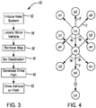
FIG. 3 is a flow chart depicting a method for autonomously parking and un-parking the motor vehicle according to the principles of the present disclosure; and -
FIG. 4 is an example of a node tree used in the method for autonomously parking and un-parking the motor vehicle. - The following description is merely exemplary in nature and is not intended to limit the present disclosure, application or uses.
- With reference to
FIG. 1 , an autonomous valet system according to the principles of the present disclosure is indicated byreference number 10. Theautonomous valet system 10 is used with anexemplary motor vehicle 12 and an exemplarymobile device 14. Themotor vehicle 12 is illustrated as a passenger vehicle, however, themotor vehicle 12 may be a truck, sport utility vehicle, van, motor home, or any other type of vehicle without departing from the scope of the present disclosure. Themobile device 14 is preferably a mobile phone, however, themobile device 14 may be a mobile computer, laptop, tablet, smart watch, or any other device in wireless communication with themotor vehicle 12. Theautonomous valet system 10 runs an autonomous valet method or application, as will be described in greater detail below. - The
autonomous valet system 10 is operable to autonomously park and un-park themotor vehicle 12. Theautonomous valet system 10 may have various configurations without departing from the scope of the present disclosure but generally includes asensor sub-system 16 and acommunication sub-system 18 each in communication with acontroller 20. Thecontroller 20 communicates with avehicle control system 22. Thesensor sub-system 16 includes a plurality ofsensors 24A-D mounted along the periphery of themotor vehicle 12. In the example provided, thesensors 24A-D are located at the front, left, right, and rear of themotor vehicle 12, respectively, to provide 360 degrees of overlapping coverage. However, it should be appreciated that thesensor sub-system 16 may have any number of sensors 24 without departing from the scope of the disclosure. Each of thesensors 24A-D is operable to collect or sense information in a predefined area surrounding themotor vehicle 12. Information from thesensors 24A-D is communicated to thecontroller 20. In a preferred embodiment, thesensors 24A-D are Light Detection and Ranging (LiDAR) sensors. However, thesensors 24A-D may be cameras, radar or sonar sensors, or any other type of proximity sensors. Thecommunication sub-system 18 includes a receiver/transmitter operable to receive and/or transmit wireless data to themobile device 14. The wireless data is communicated to thecontroller 20. In addition, thecommunication sub-system 18 may communicate with other vehicles (vehicle-to-vehicle communication), infrastructure such as a parking lot (vehicle-to-infrastructure), and may receive GPS data. - The
controller 20 is a non-generalized, electronic control device having a preprogrammed digital computer or processor, memory or non-transitory computer readable medium used to store data such as control logic, instructions, image data, lookup tables, etc., and a plurality of input/output peripherals or ports. The processor is configured to execute the control logic or instructions. Thecontroller 20 may have additional processors or additional integrated circuits in communication with the processor, such as perception logic circuits for analyzing the sensor data. - The
controller 20 may optionally communicate with a human machine interface (HMI) 26. TheHMI 26 is disposed within the cabin of themotor vehicle 12 and is preferably a touch screen accessible by an operator of themotor vehicle 12. However, theHMI 26 may be any haptic, verbal, or gesture control system without departing from the scope of the present disclosure. TheHMI 26 may be used to activate and control theautonomous valet system 10. Additionally, themobile device 14 may be used to activate and control theautonomous valet system 10. - The
vehicle control system 22 includes any systems that implement the autonomous valet functions which include parking and un-parking themotor vehicle 12. For example, thevehicle control system 22 may include a braking control system, throttle control system, steering control system, body control system, etc. Thevehicle control system 22 may also include any advanced driver assistance system (ADAS) functions that automate, adapt, or enhance vehicle systems in order to increase vehicle safety and/or operator driving performance. For example, thevehicle control system 22 may include ADAS technologies that alert the driver to potential problems or to avoid collisions by implementing safeguards, such as autonomously controlling themotor vehicle 12. Thevehicle control system 22 may also include ADAS features that enhance certain systems, such as automated lighting, adaptive cruise control, automated braking, or improved blind spot elimination using camera technology. Finally, it should be appreciated that thevehicle control system 22 may be part of theautonomous valet system 10 without departing from the scope of the present disclosure. - Turning to
FIGS. 2A and2B , an exemplary parking area is indicated byreference number 30. Theparking area 30 includes a plurality of parking spots including, in the example provided,perpendicular parking spots 32A, angledparking spots 32B, andparallel parking spots 32C. It should be appreciated that theparking area 30 may have any configuration, may be a parking structure, and may have any number and type of parking spots 32 without departing from the scope of the present disclosure. Theparking area 30 includes aparking area infrastructure 34 that may communicate with themotor vehicle 12. - With reference to
FIG. 3 , and continued reference toFIGS. 1 ,2A , and2B , a method for autonomously parking and un-parking themotor vehicle 12 in theparking area 30 is indicated byreference number 50. By way of example, themethod 50 illustrates parking themotor vehicle 12 within theparking area 30. However, it should be appreciated that themethod 50 may be used identically when un-parking or retrieving themotor vehicle 12 from theparking area 30. Themethod 50 begins atstep 52 where an operator of themotor vehicle 12 initiates or activates theautonomous valet system 10 using either theHMI 26 or themobile device 14. For example, when parking, the operator may use theHMI 26 while during un-parking the operator may use themobile device 14. - At
step 54, themotor vehicle 12 is located within, or relative to, theparking area 30. Themotor vehicle 12 may be located in theparking area 30 by positioning themotor vehicle 12 in a predefined starting location or parking spot or by GPS coordinates. Atstep 56 themotor vehicle 12 communicates with the parking area infrastructure to receive a map of theparking area 30. The map may be defined as a Cartesian coordinate system with x and y coordinates. Themotor vehicle 12 is located on the map using (x,y,Θ) coordinates, where Θ is a steering angle or a heading of themotor vehicle 12. The map of theparking area 30 includes a plurality ofpermanent obstruction zones 57 and a plurality of temporary or virtual obstruction zones 59. Thepermanent obstruction zones 57 cover areas that have fixed objects, for example lamp posts, curbs, buildings, and edge boundaries. The temporary obstruction zones 59 cover those areas where it may be desirable, based on certain factors, to prevent themotor vehicle 12 from traveling. The temporary obstruction zones 59 may be used to designate parked vehicles or parking spaces, lanes along a route, areas of theparking area 30 that are temporarily off-limits, etc. In the example provided, the temporary obstruction zones 59 include a firsttemporary obstruction zone 59A that covers a lane of a route, a secondtemporary obstruction zone 59B that covers another lane of the route, and a parked car 59C. The temporary obstruction zones 59 may be flagged as operative or inoperative by theparking area infrastructure 34 or by theautonomous valet system 10, as will be described below. - At
step 58, a destination is set in theparking area 30. In the example provided, the destination is a parking spot indicated byreference number 61 inFIG. 2A . The destination may be selected by an operator of themotor vehicle 12 or may be assigned by theparking area infrastructure 34 based on open or available parking spots 32. Alternatively, in an un-park mode, the destination location may be the location of themobile device 14, as shown inFIG. 2B . It should be appreciated that steps 54-58 may be done in various orders or simultaneously without departing from the scope of the present disclosure. - Next, at
step 60, a node tree path planner is generated from the location of themotor vehicle 12 to thedestination location 61. From the node tree path planner a lowest cost path is selected, as shown byreference number 63 inFIG. 2 . Thelowest cost path 63 operates as a path for themotor vehicle 12 to take from the starting location to thedestination location 61. Finally, atstep 62, theautonomous valet system 10 drives the mover vehicle along thelowest cost path 61 using thevehicle control system 22. Thesensor sub-system 16 may be used during autonomous driving to avoid obstacles not located in the predefined parking area map, such as pedestrians, other vehicles, etc. - Turning now to
FIG. 4 , the method of generating the node tree path planner will now be described in greater detail. The node tree path planner begins by generating a first set of nodes a1, a2, a3, a4, a5...an from the starting location Ls of themotor vehicle 12. Each node is generated a distance 'd' from the starting location Ls at a predefined turn angle φ. It should be appreciated that any number of nodes may be generated however, in a preferred embodiment, nine forward nodes are generated and nine reverse nodes are generated. The distance d may have various values but is preferably approximately 2 meters. The turn angle φ may also have various values but preferably equally divides the nodes from straight ahead to a full right turn and a full left turn. Each of the nodes is defined by (x,y,Θ) coordinates. - Next, any nodes that are blocked by the parking area map are removed or not generated. For example, each
permanent obstruction zone 57 and temporary obstruction zone 59 is defined as a quadrilateral centered on an x, y coordinate. At each newly generated node, the method determines if themotor vehicle 12 would overlap theobstruction zone 57, 59. Various methods may be used to determine the overlap, including a Point in Polygon (PIP) check. A safety factor may be used in the overlap determination. If themotor vehicle 12 at a node would overlap apermanent obstruction zone 57 the node would not be generated. If themotor vehicle 12 at a node would overlap an operative temporary obstruction zone 59 the node would not be generated. However, if themotor vehicle 12 at a node would overlap an inoperative temporary obstruction zone 59, the node would be generated. - Once the first set of nodes are generated, the node tree path planner assigns a cost to each of the nodes. The cost for each node in the first set is equal to a base cost plus a turning cost. The base cost is a function of the distance from the node to the destination location Ld. Thus, the closer the node is to the destination location Ld, the lower the base cost. The turning cost increases with an increase in the steering angle Θ. In other words, the larger the turn required to reach the node, the greater the cost. If the node is a reverse node that would require the motor vehicle to change gears, an additional reverse cost is added to the node.
- Once the nodes have been assigned a cost, the node tree path planner selects the lowest cost node, such as node a5 in the example provided, and generates another set of nodes b1, b2, b3, b4... bn from the selected lowest cost node. Each of the nodes are generated at a distance d from the node a5 at turn angles φ. Any nodes located in areas designated as
permanent obstruction zones 57 or operative temporary obstruction zones 59 are not generated, as described above. Moreover, any nodes previously generated are not generated again. Next, costs are assigned to each node b1, b2, b3, b4... bn as described above except that the base cost also includes the cost of node a5. Thus, each child node inherits the cost of the parent node from which it is generated. In one embodiment, the base cost also includes a generation cost which is a function of which generation the node is from the starting location node. For example, a generation cost may be added after between 20 or 30 generations in order to discourage further generations. In another embodiment, the cost of a child node is compared to a fixed or variable threshold value. If the cost of the child node exceeds the threshold value, the node is not generated or no further child nodes are generated from the node. The tree node path planner then selects the lowest cost node from all of the nodes generated thus far and repeats the method until a newly generated node is at the destination location Ld. - Once a node is at the location Ld, the node tree path planner traces the path back to the starting location Ls and sets the
path 63. Themotor vehicle 12 may be driven from node to node along the path or may be driven along an average or weighted curve along the path. - The temporary obstruction zones 59 may be used to influence the
path 63 generated by the path planner by selectively flagging which zones are operative or inoperative. For example,FIG. 2A illustrates themotor vehicle 12 during a park function. During the park function, thepath 63 includes an approach phase, indicated byreference number 70, and a parking phase, indicated byreference number 72. An intermediate node or location, Li, separates theapproach phase 70 from theparking phase 72. In a preferred embodiment, Li is set a predefined distance away from the destination location Ld, i.e., the parking spot. Theapproach phase 70 is defined by nodes generated between the location Ls of themotor vehicle 12 and the intermediate location Li. Theparking phase 72 is defined by nodes generated between the intermediate location Li and the destination location Ld. In order to encourage thepath 63 to keep to the right hand side of the lane, the firsttemporary obstruction zone 59A is flagged as inoperative while the secondtemporary obstruction zone 59B is flagged as operative during the approach phase. Thus, thepath 63 will generate on the right hand side. During theparking phase 72, bothzones -
FIG. 2B illustrates themotor vehicle 12 during an un-park or retrieve function. During the un-park function, thepath 63 includes an un-park phase, indicated byreference number 76, and a return phase, indicated byreference number 78. An intermediate node or location, Li2, separates theun-park phase 76 from thereturn phase 78. In a preferred embodiment, Li2 is set a predefined distance away from the destination location Ld, i.e., the parking spot. Theun-park phase 76 is defined by nodes generated between the location Ls of themotor vehicle 12 and the intermediate location Li2. Thereturn phase 78 is defined by nodes generated between the intermediate location Li2 and the destination location Ld. In order to encourage thepath 63 to keep to the right hand side of the lane, the secondtemporary obstruction zone 59B is flagged as inoperative while the firsttemporary obstruction zone 59A is flagged as operative during thereturn phase 78. Thus, thepath 63 will generate on the right hand side. During theun-park phase 76, bothzones - The temporary obstruction zones 59 may be constructed to define paths for the approach or return
phases - The description of the invention is merely exemplary in nature and variations that do not depart from the gist of the invention are intended to be within the scope of the invention. Such variations are not to be regarded as a departure from the spirit and scope of the invention.
Claims (15)
- A method (50) for autonomously driving a motor vehicle (12), the method (50) comprising:receiving a map having a first temporary obstruction zone (59A);determining a starting location (Ls) of the motor vehicle (12) relative to the map;selecting a destination location (Ld) within the map;setting the first temporary obstruction zone (59A) as operative or inoperative;generating a path from the starting location (Ls) to the destination location (Ld), wherein the path (63) does not enter the first temporary obstruction zone (59A) when operative; anddriving the motor vehicle (12) autonomously along the path (63) from the starting location (Ls) of the motor vehicle (12) to the destination location (Ld).
- The method (50) of claim 1 wherein the first temporary obstruction zone (59A) is a lane in the map.
- The method (50) of one of the preceding claims, wherein the map includes a parking area (30) and the first temporary obstruction zone (59A) is a portion of the parking area (30) that covers one or more parking spots (32) in the parking area (30).
- The method (50) of one of the preceding claims, wherein the first temporary obstruction zone (59A) when operative defines a route from the starting location (Ls) to the destination location (Ld) along which the path planner is generated.
- The method (50) of one of the preceding claims, wherein the map includes a right side lane and a left side lane along a route from the starting location (Ls) to the destination location (Ld), and the first temporary obstruction zone (59A) covers the right side lane and the first temporary obstruction zone (59A) is set as inoperative.
- The method (50) of one of the preceding claims, wherein the map includes a right side lane and a left side lane along a route from the starting location (Ls) to the destination location (Ld), and the first temporary obstruction zone (59A) covers the left side lane and the first temporary obstruction zone (59A) is set as operative.
- The method (50) of one of the preceding claims, wherein the first temporary obstruction zone (59A) is operative to prevent the path (63) from generating on a left hand side of a route and inoperative to allow the path to generate on a right hand side of a route.
- The method (50) of one of the preceding claims, wherein the first temporary obstruction zone (59A) is operative or inoperative based on the generated path.
- The method (50) of one of the preceding claims, wherein the destination location (Ld) is an open parking spot (32) in a parking area (30).
- The method (50) of one of the preceding claims, wherein the destination location (Ld) is a location of a mobile device in communication with the motor vehicle (12).
- The method (50) of one of the preceding claims, wherein the first temporary obstruction zone (59A) covers a parking spot (32), and the method includes setting the first temporary obstruction zone operative if the parking spot (32) is full and inoperative if the parking spot (32) is empty.
- The method of one of the preceding claims, further comprising generating a permanent obstruction zone (57) on the map that is always operative, wherein the path (63) does not enter the permanent obstruction zone (57).
- The method (50) of one of the preceding claims, wherein the map includes a parking area (30) having a plurality of parking spots (32) and a second temporary obstruction zone (59B), wherein the second temporary obstruction zone (52B) is flagged as either operative or inoperative, the method (50) further comprises the steps:initiating a park function;selecting the destination location (Ld), wherein the destination location (Ld) is a parking spot (32) within the parking area (30);flagging the first temporary obstruction zone (59A) as operative and the second temporary obstruction (59B) zone as inoperative;generating a path from the starting location (Ls) to the parking spot (32) wherein the path does not enter the second temporary obstruction zones when operative..
- The method (50) of claim 13 further comprising:initiating an un-park function;selecting a destination location (Ld);flagging the first temporary obstruction zone (59A) as inoperative and the second temporary obstruction zone (59B) as operative;generating a path from the parking spot (32) to the destination location (Ld) wherein the path does not enter either the first or second temporary obstruction zones (59A, 59B) when operative; anddriving the motor vehicle autonomously along the path from the parking spot (32) to the destination location (Ld).
- The method (50) of one of the preceding claims, wherein the method is an automatic valet method and wherein the map includes a parking area (30) having a plurality of obstruction zones (59) that can be flagged as either operative or inoperative, further comprising the steps
determining a starting location (Ls) of the motor vehicle (12) relative to the parking area (30);
determining a parking spot (32) within the parking area (30);
determining a pick-up location relative to the parking area (30);
generating a path (63) from the starting location (Ls) to the parking spot (32) to the pick-up location (Ld), wherein the path (63) includes an approach phase (70), a parking phase (72), an un-parking phase (76), and a return phase (78), and wherein the path (63) does not generate within an operative obstruction zone (59), and wherein an obstruction zone (59) is flagged as either operative or inoperative based on whether the path (63) is in the approach phase (70), the parking phase (72), the un-parking phase (76), and the return phase (78); and
driving the motor vehicle (12) autonomously along the path (63).
Applications Claiming Priority (1)
| Application Number | Priority Date | Filing Date | Title |
|---|---|---|---|
| US15/242,175 US10338586B2 (en) | 2016-08-19 | 2016-08-19 | Method for controlling autonomous valet system pathing for a motor vehicle |
Publications (1)
| Publication Number | Publication Date |
|---|---|
| EP3284654A1 true EP3284654A1 (en) | 2018-02-21 |
Family
ID=59676988
Family Applications (1)
| Application Number | Title | Priority Date | Filing Date |
|---|---|---|---|
| EP17184845.0A Withdrawn EP3284654A1 (en) | 2016-08-19 | 2017-08-04 | Method for controlling autonomous valet system pathing for a motor vehicle |
Country Status (3)
| Country | Link |
|---|---|
| US (1) | US10338586B2 (en) |
| EP (1) | EP3284654A1 (en) |
| CN (1) | CN107765685A (en) |
Cited By (6)
| Publication number | Priority date | Publication date | Assignee | Title |
|---|---|---|---|---|
| WO2021150814A1 (en) * | 2020-01-24 | 2021-07-29 | Continental Automotive Systems, Inc | Parking lot safety apparatus and method |
| EP3812228A4 (en) * | 2018-11-20 | 2021-08-25 | Guangzhou Xiaopeng Motors Technology Co., Ltd. | AUTOMATIC PARKING PROCESS AND SYSTEM |
| US20220019218A1 (en) * | 2018-12-20 | 2022-01-20 | Sony Group Corporation | Vehicle control device, vehicle control method, vehicle, information processing device, information processing method, and program |
| DE102020119318A1 (en) | 2020-07-22 | 2022-01-27 | Zf Cv Systems Global Gmbh | Method for coordinating a vehicle in a depot, as well as function control device and vehicle |
| US20220121203A1 (en) * | 2017-10-02 | 2022-04-21 | Toyota Jidosha Kabushiki Kaisha | Managing apparatus |
| CN119239579A (en) * | 2024-12-03 | 2025-01-03 | 成都赛力斯科技有限公司 | Parking path planning method, device, electronic device and storage medium |
Families Citing this family (24)
| Publication number | Priority date | Publication date | Assignee | Title |
|---|---|---|---|---|
| US10210760B2 (en) * | 2016-09-21 | 2019-02-19 | Dura Operating, Llc | System and method for autonomous parking of a vehicle |
| US10585431B2 (en) * | 2018-01-02 | 2020-03-10 | Ford Global Technologies, Llc | Mobile device tethering for a remote parking assist system of a vehicle |
| CN109305163A (en) * | 2018-09-28 | 2019-02-05 | 上汽通用五菱汽车股份有限公司 | Power control method, server and the automobile of automatic parking |
| KR102651410B1 (en) * | 2018-12-28 | 2024-03-28 | 현대자동차주식회사 | Automated Valet Parking System, and infrastructure and vehicle thereof |
| US11035685B2 (en) * | 2018-12-28 | 2021-06-15 | Zenuity Ab | Route planning algorithm for efficiently searching through meaningful links within a defined topology |
| KR102651411B1 (en) * | 2018-12-28 | 2024-03-27 | 현대자동차주식회사 | Automated Valet Parking System, and infrastructure and vehicle thereof |
| JP7176421B2 (en) * | 2019-01-25 | 2022-11-22 | トヨタ自動車株式会社 | parking assist device |
| JP7151526B2 (en) * | 2019-02-08 | 2022-10-12 | トヨタ自動車株式会社 | Automatic parking management device |
| JP2020187624A (en) * | 2019-05-16 | 2020-11-19 | 本田技研工業株式会社 | Vehicle control devices, vehicle control methods, and programs |
| CN112068537B (en) * | 2019-05-21 | 2023-07-07 | 宇通客车股份有限公司 | Automatic driving bus entrance/exit control method and device based on region division |
| JP7222339B2 (en) * | 2019-10-25 | 2023-02-15 | トヨタ自動車株式会社 | automatic parking system |
| JP7207262B2 (en) * | 2019-10-29 | 2023-01-18 | トヨタ自動車株式会社 | automatic parking system |
| JP7172961B2 (en) * | 2019-11-11 | 2022-11-16 | トヨタ自動車株式会社 | automatic parking system |
| KR20210068181A (en) * | 2019-11-29 | 2021-06-09 | 현대자동차주식회사 | Automated Valet Parking System, and infrastructure and vehicle thereof |
| JP7412234B2 (en) * | 2020-03-13 | 2024-01-12 | フォルシアクラリオン・エレクトロニクス株式会社 | Parking information management server, parking support device, and parking support system |
| AU2021212026A1 (en) * | 2020-08-14 | 2022-03-03 | Tusimple, Inc. | Launchpad for autonomous vehicles |
| CN113085895B (en) * | 2021-04-19 | 2022-07-22 | 陕西理工大学 | Vehicle lane change track planning method, device, equipment, storage medium and vehicle |
| JP7548164B2 (en) * | 2021-08-31 | 2024-09-10 | トヨタ自動車株式会社 | Automatic parking system, automatic parking method and program |
| US11999344B2 (en) * | 2022-02-20 | 2024-06-04 | Beijing Jingdong Qianshi Technology Co., Ltd. | System and method for selecting an intermediate parking goal in autonomous delivery |
| US12509062B2 (en) * | 2023-03-22 | 2025-12-30 | Aptiv Technologies AG | Parking path search using a modified parking path algorithm |
| CN116461500A (en) * | 2023-03-29 | 2023-07-21 | 重庆长安汽车股份有限公司 | Automatic parking and pickup method based on high-precision map and readable storage medium |
| CN116811914B (en) * | 2023-06-29 | 2024-07-19 | 重庆亿连信息科技有限公司 | Unmanned vehicle-mounted obstacle sensing system and method |
| CN116827991B (en) * | 2023-06-29 | 2024-11-26 | 重庆亿连信息科技有限公司 | Vehicle route and management system and method based on Internet of Things communication control |
| KR20250034789A (en) * | 2023-09-04 | 2025-03-11 | 삼성전자주식회사 | Real-time path search method and apparatus, and learning method of neural network for real-time path search |
Citations (5)
| Publication number | Priority date | Publication date | Assignee | Title |
|---|---|---|---|---|
| US20060212216A1 (en) * | 2005-03-17 | 2006-09-21 | Denso Corporation | In-vehicle navigation apparatus |
| WO2008032354A1 (en) * | 2006-09-11 | 2008-03-20 | Pioneer Corporation | Route search device, route search method, and others |
| DE102009029117A1 (en) * | 2009-09-02 | 2011-03-03 | Robert Bosch Gmbh | Method for supporting driving operation of motor vehicle, involves conveying navigation information to motor vehicle of external unit, and moving that motor vehicle on basis of navigation information |
| US20160125736A1 (en) * | 2014-10-31 | 2016-05-05 | Toyota Motor Engineering & Manufacturing North America, Inc. | Method to improve parking space identification in autonomous driving |
| DE102015201204A1 (en) * | 2015-01-26 | 2016-07-28 | Robert Bosch Gmbh | Valet parking system |
Family Cites Families (22)
| Publication number | Priority date | Publication date | Assignee | Title |
|---|---|---|---|---|
| FR2839031B1 (en) | 2002-04-30 | 2004-11-26 | Valeo Electronique | SYSTEM FOR CONTROLLING THE ACCESS AND / OR START OF A MOTOR VEHICLE WITH USER ALERTS |
| JP2007049561A (en) | 2005-08-11 | 2007-02-22 | Fujitsu Ten Ltd | In-vehicle communication system, in-vehicle terminal, and mobile terminal |
| JP4687395B2 (en) * | 2005-11-02 | 2011-05-25 | 株式会社エクォス・リサーチ | Parking control device |
| CN101688774A (en) | 2006-07-13 | 2010-03-31 | 威力登音响公司 | High-precision laser radar system |
| US8767190B2 (en) | 2006-07-13 | 2014-07-01 | Velodyne Acoustics, Inc. | High definition LiDAR system |
| DE102008060684B4 (en) * | 2008-03-28 | 2019-05-23 | Volkswagen Ag | Method and device for automatic parking of a motor vehicle |
| WO2010141631A1 (en) | 2009-06-02 | 2010-12-09 | Velodyne Acoustics, Inc. | Color lidar scanner |
| DE102011084993A1 (en) * | 2011-10-21 | 2013-04-25 | Robert Bosch Gmbh | Transfer of data from image data-based map services to an assistance system |
| US9429943B2 (en) | 2012-03-05 | 2016-08-30 | Florida A&M University | Artificial intelligence valet systems and methods |
| EP2849017B1 (en) * | 2013-09-12 | 2016-04-20 | Volvo Car Corporation | Method and arrangement for pick-up point retrieval timing |
| KR101906952B1 (en) * | 2013-11-08 | 2018-10-11 | 한화지상방산 주식회사 | Method for generating optimized parking path of manless driving vehicle, and manless driving vehicle adopting the method |
| US9631933B1 (en) | 2014-05-23 | 2017-04-25 | Google Inc. | Specifying unavailable locations for autonomous vehicles |
| JP5983680B2 (en) * | 2014-06-06 | 2016-09-06 | トヨタ自動車株式会社 | Automatic parking system |
| CN104260722B (en) * | 2014-09-23 | 2017-06-06 | 北京理工大学 | A kind of automated parking system |
| DE102014221771A1 (en) * | 2014-10-27 | 2016-04-28 | Robert Bosch Gmbh | Method and device for operating a parking space |
| DE102014221754A1 (en) | 2014-10-27 | 2016-04-28 | Robert Bosch Gmbh | A method of performing an automatic parking operation of a vehicle |
| DE102014224104A1 (en) * | 2014-11-26 | 2016-06-02 | Robert Bosch Gmbh | Method and device for operating a vehicle or a parking space |
| JP6354542B2 (en) * | 2014-11-26 | 2018-07-11 | 株式会社デンソー | Automatic vehicle driving system |
| US10096248B2 (en) * | 2015-06-11 | 2018-10-09 | Nissan North America, Inc. | Parking lot mapping system |
| US9696720B2 (en) * | 2015-08-27 | 2017-07-04 | Hyundai Motor Company | Apparatus and method for controlling autonomous navigation |
| CN105509747A (en) * | 2015-12-30 | 2016-04-20 | 桂林众捷新能源科技有限公司 | Unmanned automatic navigation system and unmanned automatic navigation method |
| US20170197615A1 (en) * | 2016-01-11 | 2017-07-13 | Ford Global Technologies, Llc | System and method for reverse perpendicular parking a vehicle |
-
2016
- 2016-08-19 US US15/242,175 patent/US10338586B2/en active Active
-
2017
- 2017-07-19 CN CN201710590492.8A patent/CN107765685A/en active Pending
- 2017-08-04 EP EP17184845.0A patent/EP3284654A1/en not_active Withdrawn
Patent Citations (5)
| Publication number | Priority date | Publication date | Assignee | Title |
|---|---|---|---|---|
| US20060212216A1 (en) * | 2005-03-17 | 2006-09-21 | Denso Corporation | In-vehicle navigation apparatus |
| WO2008032354A1 (en) * | 2006-09-11 | 2008-03-20 | Pioneer Corporation | Route search device, route search method, and others |
| DE102009029117A1 (en) * | 2009-09-02 | 2011-03-03 | Robert Bosch Gmbh | Method for supporting driving operation of motor vehicle, involves conveying navigation information to motor vehicle of external unit, and moving that motor vehicle on basis of navigation information |
| US20160125736A1 (en) * | 2014-10-31 | 2016-05-05 | Toyota Motor Engineering & Manufacturing North America, Inc. | Method to improve parking space identification in autonomous driving |
| DE102015201204A1 (en) * | 2015-01-26 | 2016-07-28 | Robert Bosch Gmbh | Valet parking system |
Non-Patent Citations (3)
| Title |
|---|
| CHRISTIAN LÖPER ET AL: "Automated Valet Parking as Part of an Integrated Travel Assistance", PROCEEDINGS OF THE 16TH INTERNATIONAL IEEE ANNUAL CONFERENCE ON INTELLIGENT TRANSPORTATION SYSTEMS (ITSC 2013), 6 October 2013 (2013-10-06), pages 2341 - 2348, XP055439565, Retrieved from the Internet <URL:http://ieeexplore.ieee.org/ielx7/6712176/6728201/06728577.pdf> [retrieved on 20180110], DOI: 10.1109/ITSC.2013.6728577 * |
| MARCOS GOMES PRADO: "Planejamento de trajetória para estacionamento de veículos autônomos", 1 April 2013 (2013-04-01), pages 1 - 84, XP055439434, Retrieved from the Internet <URL:http://www.teses.usp.br/teses/disponiveis/55/55134/tde-13052013-101339/publico/marcospradorevisada.pdf> [retrieved on 20180110] * |
| MAXIM LIKHACHEV ET AL: "Planning Long Dynamically Feasible Maneuvers for Autonomous Vehicles", THE INTERNATIONAL JOURNAL OF ROBOTICS RESEARCH, 1 August 2009 (2009-08-01), London, England, pages 933 - 945, XP055439546, Retrieved from the Internet <URL:http://citeseerx.ist.psu.edu/viewdoc/download?doi=10.1.1.149.23&rep=rep1&type=pdf> [retrieved on 20180110], DOI: 10.1177/0278364909340445 * |
Cited By (9)
| Publication number | Priority date | Publication date | Assignee | Title |
|---|---|---|---|---|
| US20220121203A1 (en) * | 2017-10-02 | 2022-04-21 | Toyota Jidosha Kabushiki Kaisha | Managing apparatus |
| US11782441B2 (en) * | 2017-10-02 | 2023-10-10 | Toyota Jidosha Kabushiki Kaisha | Managing apparatus |
| EP3812228A4 (en) * | 2018-11-20 | 2021-08-25 | Guangzhou Xiaopeng Motors Technology Co., Ltd. | AUTOMATIC PARKING PROCESS AND SYSTEM |
| US20220019218A1 (en) * | 2018-12-20 | 2022-01-20 | Sony Group Corporation | Vehicle control device, vehicle control method, vehicle, information processing device, information processing method, and program |
| US11815887B2 (en) * | 2018-12-20 | 2023-11-14 | Sony Group Corporation | Vehicle control device, vehicle control method, vehicle, information processing device, information processing method, and program |
| WO2021150814A1 (en) * | 2020-01-24 | 2021-07-29 | Continental Automotive Systems, Inc | Parking lot safety apparatus and method |
| DE102020119318A1 (en) | 2020-07-22 | 2022-01-27 | Zf Cv Systems Global Gmbh | Method for coordinating a vehicle in a depot, as well as function control device and vehicle |
| US12510894B2 (en) | 2020-07-22 | 2025-12-30 | Zf Cv Systems Global Gmbh | Method for coordinating a vehicle in a depot, and function control device and vehicle |
| CN119239579A (en) * | 2024-12-03 | 2025-01-03 | 成都赛力斯科技有限公司 | Parking path planning method, device, electronic device and storage medium |
Also Published As
| Publication number | Publication date |
|---|---|
| US20180052460A1 (en) | 2018-02-22 |
| CN107765685A (en) | 2018-03-06 |
| US10338586B2 (en) | 2019-07-02 |
Similar Documents
| Publication | Publication Date | Title |
|---|---|---|
| US10338586B2 (en) | Method for controlling autonomous valet system pathing for a motor vehicle | |
| US9896091B1 (en) | Optimized path planner for an autonomous valet parking system for a motor vehicle | |
| US10207704B2 (en) | Method for autonomously parking and un-parking a motor vehicle | |
| US10012986B2 (en) | Method for autonomously parking a motor vehicle for head-in, tail-in, and parallel parking spots | |
| US11393340B2 (en) | Automatic parking system and automatic parking method | |
| CN108140319B (en) | Parking assistance method and parking assistance device | |
| US11651693B2 (en) | Passenger walking points in pick-up/drop-off zones | |
| CN102334151B (en) | Movement trajectory generator | |
| JP6269552B2 (en) | Vehicle travel control device | |
| US20180364709A1 (en) | Autonomous driving control apparatus for vehicle, autonomous driving control method for vehicle, and vehicle system | |
| EP3284656A1 (en) | System and method for controlling parking functions of a motor vehicle | |
| US11605289B2 (en) | Notification device | |
| US10565875B2 (en) | Apparatus and method for parking assist | |
| US11300419B2 (en) | Pick-up/drop-off zone availability estimation using probabilistic model | |
| JPWO2019058720A1 (en) | Information processing equipment, autonomous mobile devices, and methods, and programs | |
| JP2017007572A (en) | Vehicle control device and vehicle control method | |
| JP7202982B2 (en) | Driving support method and driving support device | |
| JP2018180735A (en) | Operating range determination device | |
| US11904856B2 (en) | Detection of a rearward approaching emergency vehicle | |
| JP2019106022A (en) | Roadside object recognition device | |
| US12264922B2 (en) | Pick-up/drop-off zone tracking system | |
| JP7176651B2 (en) | Parking assistance method and parking assistance device | |
| US20200282978A1 (en) | Vehicle control system, vehicle control method, and storage medium | |
| RU2791347C1 (en) | Parking assistance method and a parking assistance device | |
| JP2021183450A (en) | Travel support method and travel support apparatus for vehicle |
Legal Events
| Date | Code | Title | Description |
|---|---|---|---|
| PUAI | Public reference made under article 153(3) epc to a published international application that has entered the european phase |
Free format text: ORIGINAL CODE: 0009012 |
|
| AK | Designated contracting states |
Kind code of ref document: A1 Designated state(s): AL AT BE BG CH CY CZ DE DK EE ES FI FR GB GR HR HU IE IS IT LI LT LU LV MC MK MT NL NO PL PT RO RS SE SI SK SM TR |
|
| AX | Request for extension of the european patent |
Extension state: BA ME |
|
| 17P | Request for examination filed |
Effective date: 20180821 |
|
| RBV | Designated contracting states (corrected) |
Designated state(s): AL AT BE BG CH CY CZ DE DK EE ES FI FR GB GR HR HU IE IS IT LI LT LU LV MC MK MT NL NO PL PT RO RS SE SI SK SM TR |
|
| 17Q | First examination report despatched |
Effective date: 20190604 |
|
| STAA | Information on the status of an ep patent application or granted ep patent |
Free format text: STATUS: THE APPLICATION IS DEEMED TO BE WITHDRAWN |
|
| 18D | Application deemed to be withdrawn |
Effective date: 20191015 |