EP3284656A1 - System and method for controlling parking functions of a motor vehicle - Google Patents
System and method for controlling parking functions of a motor vehicle Download PDFInfo
- Publication number
- EP3284656A1 EP3284656A1 EP17184850.0A EP17184850A EP3284656A1 EP 3284656 A1 EP3284656 A1 EP 3284656A1 EP 17184850 A EP17184850 A EP 17184850A EP 3284656 A1 EP3284656 A1 EP 3284656A1
- Authority
- EP
- European Patent Office
- Prior art keywords
- park
- button
- host vehicle
- automatic valet
- function
- Prior art date
- Legal status (The legal status is an assumption and is not a legal conclusion. Google has not performed a legal analysis and makes no representation as to the accuracy of the status listed.)
- Withdrawn
Links
- 230000006870 function Effects 0.000 title claims abstract description 126
- 238000000034 method Methods 0.000 title claims abstract description 48
- 238000012790 confirmation Methods 0.000 claims description 13
- 230000037452 priming Effects 0.000 claims description 6
- 230000002085 persistent effect Effects 0.000 claims description 5
- 230000004044 response Effects 0.000 claims description 4
- 238000005259 measurement Methods 0.000 claims description 3
- 238000004891 communication Methods 0.000 description 8
- 238000005516 engineering process Methods 0.000 description 5
- 230000004913 activation Effects 0.000 description 2
- 239000003086 colorant Substances 0.000 description 2
- 239000007787 solid Substances 0.000 description 2
- 230000003044 adaptive effect Effects 0.000 description 1
- 238000001514 detection method Methods 0.000 description 1
- 238000010586 diagram Methods 0.000 description 1
- 230000008030 elimination Effects 0.000 description 1
- 238000003379 elimination reaction Methods 0.000 description 1
- 230000002045 lasting effect Effects 0.000 description 1
- 230000008447 perception Effects 0.000 description 1
- 230000002093 peripheral effect Effects 0.000 description 1
- 230000002265 prevention Effects 0.000 description 1
- 239000013589 supplement Substances 0.000 description 1
- 230000000153 supplemental effect Effects 0.000 description 1
- 230000001755 vocal effect Effects 0.000 description 1
Images


Classifications
-
- B—PERFORMING OPERATIONS; TRANSPORTING
- B60—VEHICLES IN GENERAL
- B60W—CONJOINT CONTROL OF VEHICLE SUB-UNITS OF DIFFERENT TYPE OR DIFFERENT FUNCTION; CONTROL SYSTEMS SPECIALLY ADAPTED FOR HYBRID VEHICLES; ROAD VEHICLE DRIVE CONTROL SYSTEMS FOR PURPOSES NOT RELATED TO THE CONTROL OF A PARTICULAR SUB-UNIT
- B60W30/00—Purposes of road vehicle drive control systems not related to the control of a particular sub-unit, e.g. of systems using conjoint control of vehicle sub-units, or advanced driver assistance systems for ensuring comfort, stability and safety or drive control systems for propelling or retarding the vehicle
- B60W30/06—Automatic manoeuvring for parking
-
- B—PERFORMING OPERATIONS; TRANSPORTING
- B60—VEHICLES IN GENERAL
- B60W—CONJOINT CONTROL OF VEHICLE SUB-UNITS OF DIFFERENT TYPE OR DIFFERENT FUNCTION; CONTROL SYSTEMS SPECIALLY ADAPTED FOR HYBRID VEHICLES; ROAD VEHICLE DRIVE CONTROL SYSTEMS FOR PURPOSES NOT RELATED TO THE CONTROL OF A PARTICULAR SUB-UNIT
- B60W50/00—Details of control systems for road vehicle drive control not related to the control of a particular sub-unit, e.g. process diagnostic or vehicle driver interfaces
- B60W50/08—Interaction between the driver and the control system
- B60W50/082—Selecting or switching between different modes of propelling
-
- B—PERFORMING OPERATIONS; TRANSPORTING
- B62—LAND VEHICLES FOR TRAVELLING OTHERWISE THAN ON RAILS
- B62D—MOTOR VEHICLES; TRAILERS
- B62D15/00—Steering not otherwise provided for
- B62D15/02—Steering position indicators ; Steering position determination; Steering aids
- B62D15/027—Parking aids, e.g. instruction means
- B62D15/0285—Parking performed automatically
-
- B—PERFORMING OPERATIONS; TRANSPORTING
- B60—VEHICLES IN GENERAL
- B60W—CONJOINT CONTROL OF VEHICLE SUB-UNITS OF DIFFERENT TYPE OR DIFFERENT FUNCTION; CONTROL SYSTEMS SPECIALLY ADAPTED FOR HYBRID VEHICLES; ROAD VEHICLE DRIVE CONTROL SYSTEMS FOR PURPOSES NOT RELATED TO THE CONTROL OF A PARTICULAR SUB-UNIT
- B60W2420/00—Indexing codes relating to the type of sensors based on the principle of their operation
- B60W2420/40—Photo or light sensitive means, e.g. infrared sensors
- B60W2420/403—Image sensing, e.g. optical camera
-
- B60W2420/408—
-
- B—PERFORMING OPERATIONS; TRANSPORTING
- B60—VEHICLES IN GENERAL
- B60W—CONJOINT CONTROL OF VEHICLE SUB-UNITS OF DIFFERENT TYPE OR DIFFERENT FUNCTION; CONTROL SYSTEMS SPECIALLY ADAPTED FOR HYBRID VEHICLES; ROAD VEHICLE DRIVE CONTROL SYSTEMS FOR PURPOSES NOT RELATED TO THE CONTROL OF A PARTICULAR SUB-UNIT
- B60W2420/00—Indexing codes relating to the type of sensors based on the principle of their operation
- B60W2420/54—Audio sensitive means, e.g. ultrasound
-
- B—PERFORMING OPERATIONS; TRANSPORTING
- B60—VEHICLES IN GENERAL
- B60W—CONJOINT CONTROL OF VEHICLE SUB-UNITS OF DIFFERENT TYPE OR DIFFERENT FUNCTION; CONTROL SYSTEMS SPECIALLY ADAPTED FOR HYBRID VEHICLES; ROAD VEHICLE DRIVE CONTROL SYSTEMS FOR PURPOSES NOT RELATED TO THE CONTROL OF A PARTICULAR SUB-UNIT
- B60W2554/00—Input parameters relating to objects
- B60W2554/40—Dynamic objects, e.g. animals, windblown objects
- B60W2554/404—Characteristics
- B60W2554/4041—Position
-
- B—PERFORMING OPERATIONS; TRANSPORTING
- B60—VEHICLES IN GENERAL
- B60W—CONJOINT CONTROL OF VEHICLE SUB-UNITS OF DIFFERENT TYPE OR DIFFERENT FUNCTION; CONTROL SYSTEMS SPECIALLY ADAPTED FOR HYBRID VEHICLES; ROAD VEHICLE DRIVE CONTROL SYSTEMS FOR PURPOSES NOT RELATED TO THE CONTROL OF A PARTICULAR SUB-UNIT
- B60W2555/00—Input parameters relating to exterior conditions, not covered by groups B60W2552/00, B60W2554/00
- B60W2555/60—Traffic rules, e.g. speed limits or right of way
-
- B—PERFORMING OPERATIONS; TRANSPORTING
- B60—VEHICLES IN GENERAL
- B60W—CONJOINT CONTROL OF VEHICLE SUB-UNITS OF DIFFERENT TYPE OR DIFFERENT FUNCTION; CONTROL SYSTEMS SPECIALLY ADAPTED FOR HYBRID VEHICLES; ROAD VEHICLE DRIVE CONTROL SYSTEMS FOR PURPOSES NOT RELATED TO THE CONTROL OF A PARTICULAR SUB-UNIT
- B60W2720/00—Output or target parameters relating to overall vehicle dynamics
- B60W2720/12—Lateral speed
-
- B—PERFORMING OPERATIONS; TRANSPORTING
- B60—VEHICLES IN GENERAL
- B60W—CONJOINT CONTROL OF VEHICLE SUB-UNITS OF DIFFERENT TYPE OR DIFFERENT FUNCTION; CONTROL SYSTEMS SPECIALLY ADAPTED FOR HYBRID VEHICLES; ROAD VEHICLE DRIVE CONTROL SYSTEMS FOR PURPOSES NOT RELATED TO THE CONTROL OF A PARTICULAR SUB-UNIT
- B60W2720/00—Output or target parameters relating to overall vehicle dynamics
- B60W2720/24—Direction of travel
-
- G—PHYSICS
- G06—COMPUTING; CALCULATING OR COUNTING
- G06F—ELECTRIC DIGITAL DATA PROCESSING
- G06F3/00—Input arrangements for transferring data to be processed into a form capable of being handled by the computer; Output arrangements for transferring data from processing unit to output unit, e.g. interface arrangements
- G06F3/01—Input arrangements or combined input and output arrangements for interaction between user and computer
- G06F3/048—Interaction techniques based on graphical user interfaces [GUI]
- G06F3/0481—Interaction techniques based on graphical user interfaces [GUI] based on specific properties of the displayed interaction object or a metaphor-based environment, e.g. interaction with desktop elements like windows or icons, or assisted by a cursor's changing behaviour or appearance
- G06F3/0482—Interaction with lists of selectable items, e.g. menus
-
- G—PHYSICS
- G06—COMPUTING; CALCULATING OR COUNTING
- G06F—ELECTRIC DIGITAL DATA PROCESSING
- G06F3/00—Input arrangements for transferring data to be processed into a form capable of being handled by the computer; Output arrangements for transferring data from processing unit to output unit, e.g. interface arrangements
- G06F3/01—Input arrangements or combined input and output arrangements for interaction between user and computer
- G06F3/048—Interaction techniques based on graphical user interfaces [GUI]
- G06F3/0487—Interaction techniques based on graphical user interfaces [GUI] using specific features provided by the input device, e.g. functions controlled by the rotation of a mouse with dual sensing arrangements, or of the nature of the input device, e.g. tap gestures based on pressure sensed by a digitiser
- G06F3/0488—Interaction techniques based on graphical user interfaces [GUI] using specific features provided by the input device, e.g. functions controlled by the rotation of a mouse with dual sensing arrangements, or of the nature of the input device, e.g. tap gestures based on pressure sensed by a digitiser using a touch-screen or digitiser, e.g. input of commands through traced gestures
Definitions
- the invention relates generally to automated driver assistance systems for host vehicles, and more particularly to automated driver assistance systems for engaging and controlling automatic valet functions of a host vehicle.
- Smart car technologies such as free-ranging on grid navigation, as well as parking guidance and information systems, aid in the prevention of human error when drivers operate a vehicle.
- Such technologies have been used to improve navigation of roadways, and to augment the parking abilities of motor vehicle drivers while the drivers are present within the motor vehicle.
- rear view camera systems and impact alert systems have been developed to assist the operator of the motor vehicle while parking to avoid collisions.
- autonomous parking systems have been developed that autonomously park the motor vehicle in a parallel parking spot once the operator of the motor vehicle has positioned the motor vehicle in a predefined location proximate the parking spot.
- a method for directing a host vehicle to perform automatic valet functions includes receiving a first input to access an automatic valet system.
- the method further includes presenting an automatic valet system management interface having at least two selectable functions including an autonomous park function and an autonomous un-park function.
- the method further includes receiving a second input to select one of the at least two functions of the automatic valet system.
- the method further includes presenting information related to the selected function.
- the method further includes receiving a third input to direct the automatic valet system to perform the selected function.
- the method further includes presenting an option to cancel the selected function for a predetermined period of time; and presenting a status of the host vehicle as it performs the selected function.
- receiving a first input further includes selecting an automatic valet system in an HMI of a host vehicle and selecting an automatic valet system management interface on a mobile device.
- presenting an automatic valet system management interface further includes presenting a primary menu portion, a secondary menu portion, and a display portion on the mobile device.
- presenting a primary menu portion further includes presenting a plurality of buttons, each button providing access to one of the selectable functions of the automatic valet system.
- receiving a second input further includes pressing a first of the plurality of buttons for an extended duration
- receiving a third input further comprises pressing a confirmation button
- the confirmation button is displayed in the secondary menu portion only after the first of the plurality of buttons is pressed for the extended duration.
- the method in response to receiving the third input to the automatic valet system management interface, the method further includes directing the automatic valet system to perform an action corresponding to one or more of the inputs received.
- the method in response to receiving a second input to select one of the at least two functions of the automatic valet system, the method further includes displaying within the display portion automatic valet system data corresponding to a plurality of vehicle position characteristics, the plurality of vehicle position characteristics includes at least one of a distance measurement, a target location, an estimated time to the target location, a map, and a depiction of objects detected by a sensor array equipped to the vehicle.
- a method for directing a host vehicle to perform automatic valet functions includes receiving a first input to an HMI to access an automatic valet system in a host vehicle.
- the method further includes presenting an automatic valet system management interface on a mobile device in wireless communication with the host vehicle, the automatic valet system management interface having a primary menu bar, a secondary menu bar, and a display portion.
- the method further includes presenting at least two selectable functions within the primary menu bar including an autonomous park function and an autonomous un-park function.
- the method further includes receiving a second input to select one of the at least two functions of the automatic valet system.
- the method further includes presenting information related to the selected function within the display portion.
- the method further includes presenting a secondary menu bar.
- the method further includes receiving a third input to direct the automatic valet system to perform the selected function.
- the method further includes presenting within the secondary menu bar an option to cancel the selected function for a predetermined period of time, and presenting within the display portion a status of the host vehicle as it performs the selected function.
- presenting at least two selectable functions further includes presenting a plurality of buttons for selecting automatic valet system functions, and the primary menu bar is persistent.
- the plurality of buttons include a first button for receiving the second input to command the host vehicle to initiate a park function, a second button for receiving the second input to command the host vehicle to initiate an un-park function, and a third button for receiving the second input to command the host vehicle to initiate the park and/or un-park functions based on a voice command from a user.
- the receiving the second input to select one of the at least two functions further includes requiring a user to press the first button or the second button for a predetermined duration of time to activate the automatic valet system to command the vehicle to perform the selected function.
- presenting the secondary menu bar further includes presenting a confirmation button and a cancel button.
- the method further includes presenting within the display portion a status of the host vehicle automatic valet system; the status includes at least a target location, a time to the target location, and a distance to the target location.
- a system for controlling parking functions of a host vehicle includes a human machine interface (HMI) disposed within the host vehicle.
- the system further includes a parking system configured to autonomously park or un-park the host vehicle.
- the system further includes an application accessible through the HMI, the application including a primary menu bar, a secondary menu bar, and a display portion and having a selectable feature disposed in the primary menu bar for selecting a parking system function, and having a selectable feature disposed in the secondary menu bar for engaging the parking system of the host vehicle to perform the parking system function.
- the primary menu bar further includes a plurality of buttons for selecting parking system functions, and the primary menu bar is persistent throughout the application.
- the plurality of buttons includes a first button for priming the parking system to command the host vehicle to initiate a park function, a second button for priming the parking system to command the host vehicle to initiate an un-park function, and a third button for priming the parking system to initiate the park and/or un-park functions based on a voice command from a user.
- the first button and second button further include a predetermined time, and upon being pressed by a user, the first button and/or the second button only activate the parking system to command the vehicle to park and/or un-park if the first and/or second button has been pressed for the predetermined time.
- the secondary menu bar is displayed after the predetermined time has been reached, and the secondary menu bar provides a confirmation button and a cancel button.
- the display portion includes a status of the host vehicle parking system, and the status includes at least a target location, a time to the target location, and a distance to the target location.
- a system and method for directing a host vehicle to perform automatic valet functions is generally indicated by reference to automatic valet system 10.
- the system 10 is used with an exemplary host vehicle 12 and an exemplary mobile device 14.
- the host vehicle 12 is illustrated as a passenger vehicle, however, the host vehicle 12 may be a truck, sport utility vehicle, van, motor home, or any other type of vehicle without departing from the scope of the present disclosure.
- the mobile device 14 is preferably a mobile phone, however, the mobile device 14 may be a mobile computer, laptop, tablet, smart watch, or any other device in wireless communication with the host vehicle 12.
- the system 10 includes an automatic parking system 16, a human machine interface (HMI) 18, and an automatic valet application 20.
- HMI human machine interface
- the automatic parking system 16 is operable to autonomously park and un-park the host vehicle 12.
- the automatic parking system 16 may have various configurations without departing from the scope of the present disclosure but generally includes a sensor sub-system 22 and a communication sub-system 24 in communication with a controller 26.
- the controller 26 communicates with a vehicle control system 27.
- the sensor sub-system 22 includes a plurality of sensors 28A-D mounted along the periphery of the host vehicle 12. It should be appreciated that the sensor sub-system 22 may have any number of sensors 28 without departing from the scope of the disclosure.
- Each of the sensors 28A-D is operable to collect or sense information in a predefined area surrounding the host vehicle 12. Information from the sensors 28A-D is communicated to the controller 26.
- the sensors 28A-D are Light Detection and Ranging (LiDAR) sensors.
- the sensors 28A-D may be cameras, radar or sonar sensors, or any other type of proximity sensors.
- the communications sub-system 24 includes a receiver/transmitter operable to receive and/or transmit wireless data to the mobile device 14.
- the wireless data is communicated to the controller 26.
- the controller 26 is a non-generalized, electronic control device having a preprogrammed digital computer or processor, memory or non-transitory computer readable medium used to store data such as control logic, instructions, image data, lookup tables, etc., and a plurality of input/output peripherals or ports.
- the processor is configured to execute the control logic or instructions.
- the controller 26 may have additional processors or additional integrated circuits in communication with the processor, such as perception logic circuits for analyzing the sensor data.
- the vehicle control system 27 includes any systems that implement an autonomous valet functions including an autonomous park function and an autonomous un-park function.
- the vehicle control system 27 may include a braking control system, throttle control system, steering control system, body control system, etc.
- the vehicle control system 27 may also include any advanced driver assistance system (ADAS) functions that automate, adapt, or enhance vehicle systems in order to increase vehicle safety and/or operator driving performance.
- ADAS advanced driver assistance system
- the vehicle control system 27 may include ADAS technologies that alert the driver to potential problems or to avoid collisions by implementing safeguards, such as autonomously controlling the host vehicle 12.
- the vehicle control system 27 may also include ADAS features that enhance certain systems, such as automated lighting, adaptive cruise control, automated braking, or improved blind spot elimination using camera technology.
- the HMI 18 is disposed within the cabin of the host vehicle 12 and is in communication with the controller 26.
- the HMI 18 is preferably a touch screen accessible by an operator of the host vehicle 12.
- the HMI 18 may be any haptic, verbal, or gesture controls without departing from the scope of the present disclosure.
- the HMI 18 is equipped with the automatic valet application 20.
- an operator of the host vehicle 12 accesses the automatic valet application 20 through selecting an icon corresponding to the automatic valet application 20 on the HMI 18.
- the mobile device 14 is also equipped with the automatic valet application 20.
- the operator of the host vehicle 12 accesses the automatic valet application 20 through the HMI 18, and/or the mobile device 14.
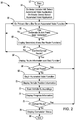
- a method 50 for directing the host vehicle 12 to perform automatic valet functions using the automatic valet application 20 begins at block 52.
- the automatic valet application 20 is accessed via either the HMI 18 or the mobile device 14. While for ease of explanation, the discussion that follows focuses on accessing the automatic valet application 20 through the HMI 18, it should be understood that the automatic valet application 20 may also be accessed and used from any mobile device 14 in wireless communication with the host vehicle 12, and onto which the automatic valet application 20 has been installed.
- the mobile device 14 can be substituted or used as a supplement to the HMI 18 without departing from the scope or intent of this disclosure.
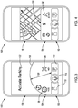
- the HMI 18 displays an automatic valet system management interface 100, shown in FIG. 3 .
- the automatic valet system management interface 100 is subdivided into at least three portions, including a primary menu bar 102, a secondary menu bar 104, and a display portion 106.
- the primary menu bar 102 has a persistent on-screen presence whenever the system management interface 100 is being displayed. That is, the primary menu bar 102 remains on-screen during the duration of the use of the system management interface 100.
- the primary menu bar 102 presents at least two selectable functions including an autonomous park function, and an autonomous un-park or retrieval function.
- the operator presses a corresponding park button 108 within the primary menu bar 102 at block 56.
- the operator presses a corresponding un-park button 110 within the primary menu bar 102.
- a voice button 116 is also presented within the primary menu bar 102. The voice button 116 engages a microphone (not shown) of the host vehicle 12 or the mobile device 14 for receiving from the host vehicle operator voice commands to direct the automated valet system 10 to park or un-park the host vehicle 12.
- the automatic valet application 20 requires a deliberate button press on the part of the operator.
- the automatic valet application 20 deliberate button press requires the operator to press and hold the park or un-park button 108, 110 for a predetermined duration.
- the predetermined duration is a period of time for a button press that has been determined to be of greater duration than a majority of unintentional button presses.
- the button press may be in the range of 0-10 seconds.
- the display portion 106 of the system management interface 100 displays data corresponding to the button being pressed. For example, the display portion 106 displays a counter 118, or message corresponding to the park function 108.
- the counter 118 is a semi-circular, radially-expanding shaded portion of the system management interface 100.
- the counter 118 remains on-screen and a counter radius 120 extends until the predetermined duration for the deliberate button press has been met.
- the display portion 106 displays a message 122 corresponding to the function being accessed.
- the message 122 includes the text, "Activate Parking.” Additional information corresponding to the function being selected during the deliberate button press may be displayed without departing form the scope or intent of this disclosure.
- the display portion 106 may also display a warning semaphore, color-coded message, etc. corresponding to the function being selected.
- the deliberate button press is discussed as having an extended duration, it should be understood that the deliberate button press may also be a button press having a specific pattern, such as multiple short-duration button presses within a predetermined period of time, without departing from the scope or intent of this disclosure.
- the park or un-park function on the automated valet system management interface 100 has been selected. Selecting the park or un-park function on the system management interface 100 causes the secondary menu bar 104 to be displayed on-screen on the HMI 18.
- the secondary menu bar 104 is a supplemental menu bar that is non-persistent. That is, the secondary menu bar 104 is only displayed on-screen for certain portions of the duration during which the system management interface 100 is in use. In one aspect, the secondary menu bar 104 is displayed after the selection of the park or un-park functions from within the primary menu bar 102.
- the secondary menu bar 104 presents at least two selectable functions including a confirmation function and a first cancellation function.
- the confirmation function is activated by pressing a corresponding confirmation button 126, and the first cancellation function is engaged by pressing a corresponding first cancellation button 128.
- the confirmation function activates the automatic valet system 10 to perform an autonomous park or un-park function selected by the deliberate button press of the park or un-park button 108, 110 within the primary menu bar 102.
- the first cancellation function 128 cancels the activation of the autonomous park or un-park function selected by the deliberate button press of the park or un-park button 108, 110 within the primary menu bar 102. If the first cancellation function is chosen, the method returns to block 56, and the automatic valet system management interface 100 awaits further operator input. However, if the confirmation function is selected, the method proceeds to block 64.
- the secondary menu bar 104 and the display portion 106 display a first route information 129. Furthermore, the secondary menu bar 104 displays at least one additional selectable function.
- the first route information 129 includes information about parking locations, parking prices, parking distance, and distance to parking lots, maps, etc.
- the at least one additional selectable function is a start function having a corresponding start button 130 for engaging the previously selected park or un-park function.
- the secondary menu bar 104 displays a second cancellation option (not shown) for a predetermined period of time.
- the predetermined period of time is approximately ten seconds.
- the additional selectable function may also be a route selection function, a route timing function, a parking lot selection function, etc.
- the predetermined period of time is described as lasting for approximately ten seconds, the predetermined period of time may have a duration that is longer or shorter than ten seconds without departing from the scope or intent of the present disclosure.
- the display portion 106 presents a first vehicle position or status data 132 at block 70.
- a plurality of exterior sensors mounted to the host vehicle 12 scan the host vehicle's 12 surroundings at block 72.
- the results of the scans are depicted in the display portion 106 as an image of the host vehicle 12 within a circular graphic 134.
- the circular graphic 134 is a graphical representation of the data acquired from a plurality of exterior sensors mounted to the host vehicle 12.
- the data acquired from the plurality of exterior sensor includes information regarding the presence of objects detected within a predetermined radius of the host vehicle 12.
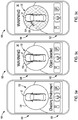
- the circular graphic 134 When an object is detected within the predetermined radius of the host vehicle 12, as in FIG. 5b , a location of the object is depicted within the circular graphic 134, by displaying a segment 135 of the circular graphic 134 in a contrasting color, and the host vehicle 12 will take an action to avoid the object.
- the circular graphic 134 is colored blue
- the location of the object is depicted as a solid red segment 136 of the circular graphic 134 corresponding to the area in which the object has been detected.
- the first vehicle position data 132 includes information regarding whether a door 138 of the host vehicle 12 is open.
- the entirety of the circular graphic 134 is displayed in red, as in FIG. 5c , and the automated valet system 10 will prohibit the host vehicle 12 from moving.
- the first vehicle position data 132 is described as being displayed in a circular graphic 134, and being displayed in solid blue and red colors, it should be appreciated that the first vehicle position data 132 may also be displayed with other shapes, colors, and patterns without departing from the scope or intent of this disclosure.
- a second vehicle position data 140 is displayed within the display portion 106 at block 74.
- the second vehicle position data 140 includes a target location.
- the target location corresponds with the respective location commanded by the park or un-park functions. That is, when a park command has been generated, the target location corresponds to a parking space, a parking lot, or a parking space within a parking lot, and when an un-park command has been generated, the target location corresponds to a position of the operator.
- the park and/or un-park target locations are generated with respect to the position of the operator's mobile device 14, using a position of the host vehicle 12 as a reference position.
- the second vehicle position data 140 includes a distance measurement that is a calculated distance between the operator's mobile device 14 and the host vehicle 12.
- the second vehicle position data 140 also includes an estimated time to the target location.
- the estimated time to the target location is an estimate of the quantity of time a route between the host vehicle 12 position and the operator's mobile device 14, and the estimate includes known speed limits, global positioning system (GPS) data, traffic conditions on the route, etc.
- GPS global positioning system
- the secondary menu bar 104 is presented to the operator.
- the secondary menu bar 104 presents at least one selectable function at block 76, including a third cancellation function.
- the operator selects the third cancellation function by pressing a corresponding third cancellation button 142, the host vehicle 12 returns to the position from which the host vehicle 12 originated, and the method returns to block 56. That is, for an example in which the automated park function has been engaged, pressing the third cancellation button 142 will cause the host vehicle 12 to return to the operator rather than proceeding to park. Similarly, for an example in which the automated un-park function has been engaged, pressing the third cancellation button 142 will cause the host vehicle 12 to return to a parking location from which the host vehicle 12 had departed. However, when the operator does not select the third cancellation function, the method proceeds to block 78.
- the display portion 106 presents a written completion message 144 at block 78.
- the completion message 144 states that the host vehicle 12 has been parked.
- the completion message 144 states that the host vehicle 12 has been un-parked, retrieved, or that the host vehicle 12 is otherwise ready for the operator's use.
- completion message 144 has been described as a written message indicating whether the car has been parked or un-parked, it should be understood that the completion message 144 may also be color-coded, a pictogram, a semaphore, etc., and may include additional host vehicle 12 or route status information without departing from the scope or intent of this disclosure.
- the method 50 ends.
- an operator of the host vehicle 12 is able to more efficiently, safely, and accurately park and/or un-park the host vehicle 12.
- the automated valet system 10 can be used by the host vehicle 12 operator to provide increased levels of autonomous driving.
Abstract
Description
- The invention relates generally to automated driver assistance systems for host vehicles, and more particularly to automated driver assistance systems for engaging and controlling automatic valet functions of a host vehicle.
- The statements in this section merely provide background information related to the present disclosure and may or may not constitute prior art.
- Smart car technologies such as free-ranging on grid navigation, as well as parking guidance and information systems, aid in the prevention of human error when drivers operate a vehicle. Such technologies have been used to improve navigation of roadways, and to augment the parking abilities of motor vehicle drivers while the drivers are present within the motor vehicle. For example, rear view camera systems and impact alert systems have been developed to assist the operator of the motor vehicle while parking to avoid collisions. In addition, autonomous parking systems have been developed that autonomously park the motor vehicle in a parallel parking spot once the operator of the motor vehicle has positioned the motor vehicle in a predefined location proximate the parking spot.
- While these systems are useful for their intended purpose, they require that the operator of the motor vehicle locate the parking spot and drive to the parking spot. Thus, there is a need in the art for improved smart car technologies that utilize preexisting infrastructure to autonomously park a motor vehicle. Moreover, there is a need to implement automatic parking systems in motor vehicles that do not increase cost, and which also increase the accuracy and robustness of parking systems while providing additional redundant ease of access and safety features.
- In accordance with one aspect of the present invention a method for directing a host vehicle to perform automatic valet functions includes receiving a first input to access an automatic valet system. The method further includes presenting an automatic valet system management interface having at least two selectable functions including an autonomous park function and an autonomous un-park function. The method further includes receiving a second input to select one of the at least two functions of the automatic valet system. The method further includes presenting information related to the selected function. The method further includes receiving a third input to direct the automatic valet system to perform the selected function. The method further includes presenting an option to cancel the selected function for a predetermined period of time; and presenting a status of the host vehicle as it performs the selected function.
- In another aspect of the present invention receiving a first input further includes selecting an automatic valet system in an HMI of a host vehicle and selecting an automatic valet system management interface on a mobile device.
- In yet another aspect of the present invention presenting an automatic valet system management interface further includes presenting a primary menu portion, a secondary menu portion, and a display portion on the mobile device.
- In yet another aspect of the present invention presenting a primary menu portion further includes presenting a plurality of buttons, each button providing access to one of the selectable functions of the automatic valet system.
- In yet another aspect of the present invention receiving a second input further includes pressing a first of the plurality of buttons for an extended duration the receiving a third input further comprises pressing a confirmation button, and the confirmation button is displayed in the secondary menu portion only after the first of the plurality of buttons is pressed for the extended duration.
- In yet another aspect of the present invention in response to receiving the third input to the automatic valet system management interface, the method further includes directing the automatic valet system to perform an action corresponding to one or more of the inputs received.
- In yet another aspect of the present invention in response to receiving a second input to select one of the at least two functions of the automatic valet system, the method further includes displaying within the display portion automatic valet system data corresponding to a plurality of vehicle position characteristics, the plurality of vehicle position characteristics includes at least one of a distance measurement, a target location, an estimated time to the target location, a map, and a depiction of objects detected by a sensor array equipped to the vehicle.
- In yet another aspect of the present invention a method for directing a host vehicle to perform automatic valet functions includes receiving a first input to an HMI to access an automatic valet system in a host vehicle. The method further includes presenting an automatic valet system management interface on a mobile device in wireless communication with the host vehicle, the automatic valet system management interface having a primary menu bar, a secondary menu bar, and a display portion. The method further includes presenting at least two selectable functions within the primary menu bar including an autonomous park function and an autonomous un-park function. The method further includes receiving a second input to select one of the at least two functions of the automatic valet system. The method further includes presenting information related to the selected function within the display portion. The method further includes presenting a secondary menu bar. The method further includes receiving a third input to direct the automatic valet system to perform the selected function. The method further includes presenting within the secondary menu bar an option to cancel the selected function for a predetermined period of time, and presenting within the display portion a status of the host vehicle as it performs the selected function.
- In yet another aspect of the present invention presenting at least two selectable functions further includes presenting a plurality of buttons for selecting automatic valet system functions, and the primary menu bar is persistent.
- In yet another aspect of the present invention the plurality of buttons include a first button for receiving the second input to command the host vehicle to initiate a park function, a second button for receiving the second input to command the host vehicle to initiate an un-park function, and a third button for receiving the second input to command the host vehicle to initiate the park and/or un-park functions based on a voice command from a user.
- In yet another aspect of the present invention the receiving the second input to select one of the at least two functions further includes requiring a user to press the first button or the second button for a predetermined duration of time to activate the automatic valet system to command the vehicle to perform the selected function.
- In yet another aspect of the present invention presenting the secondary menu bar further includes presenting a confirmation button and a cancel button.
- In yet another aspect of the present invention the method further includes presenting within the display portion a status of the host vehicle automatic valet system; the status includes at least a target location, a time to the target location, and a distance to the target location.
- In yet another aspect of the present invention a system for controlling parking functions of a host vehicle includes a human machine interface (HMI) disposed within the host vehicle. The system further includes a parking system configured to autonomously park or un-park the host vehicle. The system further includes an application accessible through the HMI, the application including a primary menu bar, a secondary menu bar, and a display portion and having a selectable feature disposed in the primary menu bar for selecting a parking system function, and having a selectable feature disposed in the secondary menu bar for engaging the parking system of the host vehicle to perform the parking system function.
- In yet another aspect of the present invention the primary menu bar further includes a plurality of buttons for selecting parking system functions, and the primary menu bar is persistent throughout the application.
- In yet another aspect of the present invention the plurality of buttons includes a first button for priming the parking system to command the host vehicle to initiate a park function, a second button for priming the parking system to command the host vehicle to initiate an un-park function, and a third button for priming the parking system to initiate the park and/or un-park functions based on a voice command from a user.
- In yet another aspect of the present invention the first button and second button further include a predetermined time, and upon being pressed by a user, the first button and/or the second button only activate the parking system to command the vehicle to park and/or un-park if the first and/or second button has been pressed for the predetermined time.
- In yet another aspect of the present invention the secondary menu bar is displayed after the predetermined time has been reached, and the secondary menu bar provides a confirmation button and a cancel button.
- In yet another aspect of the present invention the display portion includes a status of the host vehicle parking system, and the status includes at least a target location, a time to the target location, and a distance to the target location.
- The drawings described herein are for illustration purposes only and are not intended to limit the scope of the present disclosure in any way. The components in the figures are not necessarily to scale, emphasis instead being placed upon illustrating the principles of the invention. Moreover, in the figures, like reference numerals designate corresponding parts throughout the views. In the drawings:
-
FIG. 1 is a schematic diagram of a host vehicle having an automatic valet system according to the principles of the present disclosure; -
FIG. 2 is a flow chart depicting a method for using the automatic valet system according to the principles of the present disclosure; -
FIG. 3 is a screen shot of an automatic valet system management interface of the automatic valet system, the interface displaying a several selectable functions according to the principles of the present disclosure; -
FIG. 4 is a screen shot of the automatic valet system management interface of the automatic valet system, the interface displaying additional selectable functions according to the principles of the present disclosure; -
FIG. 5a is a screen shot of the automatic valet system management interface of the automatic valet system displaying sensor scan information according to the principles of the present disclosure; -
FIG. 5b is a screen shot of the automatic valet system management interface of the automatic valet system displaying sensor scan information according to the principles of the present disclosure; -
FIG. 5c is a screen shot of the automatic valet system management interface of the automatic valet system displaying sensor scan information according to the principles of the present disclosure; -
FIG. 6 is a screen shot of the automatic valet system management interface of the automatic valet system displaying host vehicle position information according to the principles of the present disclosure; and -
FIG. 7 is a screen shot of the automatic valet system management interface displaying a completion status a selectable function of the automatic valet system according to the principles of the present disclosure. - The following description is merely exemplary in nature and is not intended to limit the present disclosure, application or uses.
- With reference to
FIG. 1 a system and method for directing a host vehicle to perform automatic valet functions is generally indicated by reference toautomatic valet system 10. Thesystem 10 is used with anexemplary host vehicle 12 and an exemplarymobile device 14. Thehost vehicle 12 is illustrated as a passenger vehicle, however, thehost vehicle 12 may be a truck, sport utility vehicle, van, motor home, or any other type of vehicle without departing from the scope of the present disclosure. Themobile device 14 is preferably a mobile phone, however, themobile device 14 may be a mobile computer, laptop, tablet, smart watch, or any other device in wireless communication with thehost vehicle 12. Thesystem 10 includes anautomatic parking system 16, a human machine interface (HMI) 18, and anautomatic valet application 20. - The
automatic parking system 16 is operable to autonomously park and un-park thehost vehicle 12. Theautomatic parking system 16 may have various configurations without departing from the scope of the present disclosure but generally includes asensor sub-system 22 and acommunication sub-system 24 in communication with acontroller 26. Thecontroller 26 communicates with avehicle control system 27. Thesensor sub-system 22 includes a plurality ofsensors 28A-D mounted along the periphery of thehost vehicle 12. It should be appreciated that thesensor sub-system 22 may have any number of sensors 28 without departing from the scope of the disclosure. Each of thesensors 28A-D is operable to collect or sense information in a predefined area surrounding thehost vehicle 12. Information from thesensors 28A-D is communicated to thecontroller 26. In a preferred embodiment, thesensors 28A-D are Light Detection and Ranging (LiDAR) sensors. However, thesensors 28A-D may be cameras, radar or sonar sensors, or any other type of proximity sensors. Thecommunications sub-system 24 includes a receiver/transmitter operable to receive and/or transmit wireless data to themobile device 14. The wireless data is communicated to thecontroller 26. Thecontroller 26 is a non-generalized, electronic control device having a preprogrammed digital computer or processor, memory or non-transitory computer readable medium used to store data such as control logic, instructions, image data, lookup tables, etc., and a plurality of input/output peripherals or ports. The processor is configured to execute the control logic or instructions. Thecontroller 26 may have additional processors or additional integrated circuits in communication with the processor, such as perception logic circuits for analyzing the sensor data. - The
vehicle control system 27 includes any systems that implement an autonomous valet functions including an autonomous park function and an autonomous un-park function. For example, thevehicle control system 27 may include a braking control system, throttle control system, steering control system, body control system, etc. Thevehicle control system 27 may also include any advanced driver assistance system (ADAS) functions that automate, adapt, or enhance vehicle systems in order to increase vehicle safety and/or operator driving performance. For example, thevehicle control system 27 may include ADAS technologies that alert the driver to potential problems or to avoid collisions by implementing safeguards, such as autonomously controlling thehost vehicle 12. Thevehicle control system 27 may also include ADAS features that enhance certain systems, such as automated lighting, adaptive cruise control, automated braking, or improved blind spot elimination using camera technology. - The
HMI 18 is disposed within the cabin of thehost vehicle 12 and is in communication with thecontroller 26. TheHMI 18 is preferably a touch screen accessible by an operator of thehost vehicle 12. However, theHMI 18 may be any haptic, verbal, or gesture controls without departing from the scope of the present disclosure. TheHMI 18 is equipped with theautomatic valet application 20. In a preferred embodiment, an operator of thehost vehicle 12 accesses theautomatic valet application 20 through selecting an icon corresponding to theautomatic valet application 20 on theHMI 18. Themobile device 14 is also equipped with theautomatic valet application 20. In one aspect, the operator of thehost vehicle 12 accesses theautomatic valet application 20 through theHMI 18, and/or themobile device 14. - Turning now to
FIGS. 2 and3 , and with continuing reference toFIG. 1 , amethod 50 for directing thehost vehicle 12 to perform automatic valet functions using theautomatic valet application 20 begins atblock 52. Atblock 54, theautomatic valet application 20 is accessed via either theHMI 18 or themobile device 14. While for ease of explanation, the discussion that follows focuses on accessing theautomatic valet application 20 through theHMI 18, it should be understood that theautomatic valet application 20 may also be accessed and used from anymobile device 14 in wireless communication with thehost vehicle 12, and onto which theautomatic valet application 20 has been installed. Thus, for each reference in which theautomatic valet application 20 is discussed as being accessed on theHMI 18 of thehost vehicle 12, it should be understood that themobile device 14 can be substituted or used as a supplement to theHMI 18 without departing from the scope or intent of this disclosure. - Once the
automatic valet application 20 has been selected on theHMI 18, theHMI 18 displays an automatic valetsystem management interface 100, shown inFIG. 3 . The automatic valetsystem management interface 100 is subdivided into at least three portions, including aprimary menu bar 102, asecondary menu bar 104, and adisplay portion 106. Theprimary menu bar 102 has a persistent on-screen presence whenever thesystem management interface 100 is being displayed. That is, theprimary menu bar 102 remains on-screen during the duration of the use of thesystem management interface 100. Theprimary menu bar 102 presents at least two selectable functions including an autonomous park function, and an autonomous un-park or retrieval function. - In order to engage the autonomous park function of the
host vehicle 12, the operator presses acorresponding park button 108 within theprimary menu bar 102 atblock 56. Similarly, when the operator wishes to engage the autonomous un-park or retrieval function, the operator presses a correspondingun-park button 110 within theprimary menu bar 102. In one aspect, avoice button 116 is also presented within theprimary menu bar 102. Thevoice button 116 engages a microphone (not shown) of thehost vehicle 12 or themobile device 14 for receiving from the host vehicle operator voice commands to direct theautomated valet system 10 to park or un-park thehost vehicle 12. To reduce the likelihood of unintentional activation of the autonomous park or un-park functions, atblock 58 theautomatic valet application 20 requires a deliberate button press on the part of the operator. If the deliberate button press is not detected by theautomatic valet application 20, the method returns to block 56. Theautomatic valet application 20 deliberate button press requires the operator to press and hold the park orun-park button display portion 106 of thesystem management interface 100 displays data corresponding to the button being pressed. For example, thedisplay portion 106 displays acounter 118, or message corresponding to thepark function 108. In one aspect, thecounter 118 is a semi-circular, radially-expanding shaded portion of thesystem management interface 100. In the example, thecounter 118 remains on-screen and acounter radius 120 extends until the predetermined duration for the deliberate button press has been met. Additionally, thedisplay portion 106 displays amessage 122 corresponding to the function being accessed. In the example in which thepark function 108 is being selected by the operator, themessage 122 includes the text, "Activate Parking." Additional information corresponding to the function being selected during the deliberate button press may be displayed without departing form the scope or intent of this disclosure. For example, while thedisplay portion 106 is described as displaying acounter 118, and amessage 122, thedisplay portion 106 may also display a warning semaphore, color-coded message, etc. corresponding to the function being selected. Furthermore, while the deliberate button press is discussed as having an extended duration, it should be understood that the deliberate button press may also be a button press having a specific pattern, such as multiple short-duration button presses within a predetermined period of time, without departing from the scope or intent of this disclosure. - At
block 60, once the deliberate button press has been detected, the park or un-park function on the automated valetsystem management interface 100 has been selected. Selecting the park or un-park function on thesystem management interface 100 causes thesecondary menu bar 104 to be displayed on-screen on theHMI 18. Thesecondary menu bar 104 is a supplemental menu bar that is non-persistent. That is, thesecondary menu bar 104 is only displayed on-screen for certain portions of the duration during which thesystem management interface 100 is in use. In one aspect, thesecondary menu bar 104 is displayed after the selection of the park or un-park functions from within theprimary menu bar 102. Atblock 62, thesecondary menu bar 104 presents at least two selectable functions including a confirmation function and a first cancellation function. The confirmation function is activated by pressing acorresponding confirmation button 126, and the first cancellation function is engaged by pressing a correspondingfirst cancellation button 128. The confirmation function activates theautomatic valet system 10 to perform an autonomous park or un-park function selected by the deliberate button press of the park orun-park button primary menu bar 102. Thefirst cancellation function 128 cancels the activation of the autonomous park or un-park function selected by the deliberate button press of the park orun-park button primary menu bar 102. If the first cancellation function is chosen, the method returns to block 56, and the automatic valetsystem management interface 100 awaits further operator input. However, if the confirmation function is selected, the method proceeds to block 64. - Turning now to
FIG. 4 , and with continuing reference toFIGS. 1-3 , atblock 64 once the operator has pressed theconfirmation button 126 to engage the previously selected park or un-park function, thesecondary menu bar 104 and thedisplay portion 106 display afirst route information 129. Furthermore, thesecondary menu bar 104 displays at least one additional selectable function. In one aspect, thefirst route information 129 includes information about parking locations, parking prices, parking distance, and distance to parking lots, maps, etc. The at least one additional selectable function is a start function having acorresponding start button 130 for engaging the previously selected park or un-park function. Furthermore, once thestart button 130 has been selected to engage the previously selected park or un-park function, atblock 66 thesecondary menu bar 104 displays a second cancellation option (not shown) for a predetermined period of time. During the predetermined period of time, engagement of the previously selected park or un-park function is paused. In one aspect, the predetermined period of time is approximately ten seconds. When the second cancellation option is selected, the method returns to block 56 and the automated valetsystem management interface 100 awaits further input from the operator. However, if the second cancellation option is not selected, the method proceeds to block 68 where the previously selected automated valet function is engaged. Moreover, while the at least one additional selectable function is discussed as being a start function, it should be appreciated that the additional selectable function may also be a route selection function, a route timing function, a parking lot selection function, etc. Additionally, it should be understood that while the predetermined period of time is described as lasting for approximately ten seconds, the predetermined period of time may have a duration that is longer or shorter than ten seconds without departing from the scope or intent of the present disclosure. - Referring now to
FIGS. 5a-c , and with continuing reference toFIGS. 1-4 , once the automated park or un-park function has been engaged thedisplay portion 106 presents a first vehicle position orstatus data 132 atblock 70. To generate the vehicle position orstatus data 132, a plurality of exterior sensors (not shown) mounted to thehost vehicle 12 scan the host vehicle's 12 surroundings atblock 72. The results of the scans are depicted in thedisplay portion 106 as an image of thehost vehicle 12 within a circular graphic 134. The circular graphic 134 is a graphical representation of the data acquired from a plurality of exterior sensors mounted to thehost vehicle 12. The data acquired from the plurality of exterior sensor includes information regarding the presence of objects detected within a predetermined radius of thehost vehicle 12. When an object is detected within the predetermined radius of thehost vehicle 12, as inFIG. 5b , a location of the object is depicted within the circular graphic 134, by displaying asegment 135 of the circular graphic 134 in a contrasting color, and thehost vehicle 12 will take an action to avoid the object. In an example in which the circular graphic 134 is colored blue, for an object detected within the predetermined radius, the location of the object is depicted as a solid red segment 136 of the circular graphic 134 corresponding to the area in which the object has been detected. Additionally, the firstvehicle position data 132 includes information regarding whether adoor 138 of thehost vehicle 12 is open. In an example in which adoor 138 of thehost vehicle 12 is open, the entirety of the circular graphic 134 is displayed in red, as inFIG. 5c , and theautomated valet system 10 will prohibit thehost vehicle 12 from moving. While the firstvehicle position data 132 is described as being displayed in a circular graphic 134, and being displayed in solid blue and red colors, it should be appreciated that the firstvehicle position data 132 may also be displayed with other shapes, colors, and patterns without departing from the scope or intent of this disclosure. - Referring now to
FIG. 6 , and with further reference toFIGS. 1-5c , once thehost vehicle 12 has engaged the park or un-park function, a secondvehicle position data 140 is displayed within thedisplay portion 106 atblock 74. The secondvehicle position data 140 includes a target location. The target location corresponds with the respective location commanded by the park or un-park functions. That is, when a park command has been generated, the target location corresponds to a parking space, a parking lot, or a parking space within a parking lot, and when an un-park command has been generated, the target location corresponds to a position of the operator. Moreover, in an example in which the park and/or un-park commands are generated from the operator'smobile device 14, the park and/or un-park target locations are generated with respect to the position of the operator'smobile device 14, using a position of thehost vehicle 12 as a reference position. Similarly, the secondvehicle position data 140 includes a distance measurement that is a calculated distance between the operator'smobile device 14 and thehost vehicle 12. The secondvehicle position data 140 also includes an estimated time to the target location. The estimated time to the target location is an estimate of the quantity of time a route between thehost vehicle 12 position and the operator'smobile device 14, and the estimate includes known speed limits, global positioning system (GPS) data, traffic conditions on the route, etc. - As the
host vehicle 12 proceeds to complete the park or un-park function, thesecondary menu bar 104 is presented to the operator. Thesecondary menu bar 104 presents at least one selectable function atblock 76, including a third cancellation function. When the operator selects the third cancellation function by pressing a correspondingthird cancellation button 142, thehost vehicle 12 returns to the position from which thehost vehicle 12 originated, and the method returns to block 56. That is, for an example in which the automated park function has been engaged, pressing thethird cancellation button 142 will cause thehost vehicle 12 to return to the operator rather than proceeding to park. Similarly, for an example in which the automated un-park function has been engaged, pressing thethird cancellation button 142 will cause thehost vehicle 12 to return to a parking location from which thehost vehicle 12 had departed. However, when the operator does not select the third cancellation function, the method proceeds to block 78. - Referring now to
FIG. 7 , and with continuing reference toFIGS. 1-6 , once thehost vehicle 12 has completed the automated park or un-park function, thedisplay portion 106 presents a writtencompletion message 144 atblock 78. In the example ofFIG. 7 , in which an automated park command has been given to thehost vehicle 12, thecompletion message 144 states that thehost vehicle 12 has been parked. Similarly, in an example in which an automated un-park command has been given to thehost vehicle 12, thecompletion message 144 states that thehost vehicle 12 has been un-parked, retrieved, or that thehost vehicle 12 is otherwise ready for the operator's use. While thecompletion message 144 has been described as a written message indicating whether the car has been parked or un-parked, it should be understood that thecompletion message 144 may also be color-coded, a pictogram, a semaphore, etc., and may includeadditional host vehicle 12 or route status information without departing from the scope or intent of this disclosure. Atblock 80, themethod 50 ends. - By utilizing the
automated valet system 10 in conjunction with the plurality ofhost vehicle 12 sensors 28, an operator of thehost vehicle 12 is able to more efficiently, safely, and accurately park and/or un-park thehost vehicle 12. Moreover, theautomated valet system 10 can be used by thehost vehicle 12 operator to provide increased levels of autonomous driving. - The description of the invention is merely exemplary in nature and variations that do not depart from the gist of the invention are intended to be within the scope of the invention. Such variations are not to be regarded as a departure from the spirit and scope of the invention.
Claims (15)
- A method (50) for directing a host vehicle (12) to perform automatic valet functions, the method (50) comprising:receiving a first input to access an automatic valet system (10);presenting an automatic valet system management interface (100) having at least two selectable functions including an autonomous park function and an autonomous un-park function;receiving a second input to select one of the at least two functions of the automatic valet system (10);presenting information related to the selected function;receiving a third input to direct the automatic valet system (10) to perform the selected function;presenting an option to cancel the selected function for a predetermined period of time; andpresenting a status of the host vehicle (12) as it performs the selected function.
- The method (50) of claim 1 wherein the receiving a first input further comprises selecting an automatic valet system (10) in an HMI (18) of a host vehicle (12) and/or selecting an automatic valet system management interface (100) on a mobile device (14).
- The method (50) of one of the preceding claims, wherein presenting an automatic valet system management interface (100) further comprises presenting a primary menu portion, a secondary menu portion, and a display portion (106) on the mobile device (14).
- The method (50) of claim 3 wherein the presenting a primary menu portion further comprises presenting a plurality of buttons, each button providing access to one of the selectable functions of the automatic valet system (10).
- The method (50) of one of the preceding claims, wherein the receiving a second input further comprises pressing a first of the plurality of buttons for an extended duration the receiving a third input further comprises pressing a confirmation button; wherein the confirmation button is displayed in the secondary menu portion only after the first of the plurality of buttons is pressed for the extended duration.
- The method (50) of claim 5 wherein in response to receiving the third input to the automatic valet system management interface (100), the method (50) further comprises directing the automatic valet system (10) to perform an action corresponding to one or more of the inputs received.
- The method (50) of claim 6 wherein in response to receiving a second input to select one of the at least two functions of the automatic valet system (10), the method (50) further comprises displaying within the display portion (106) automatic valet system data corresponding to a plurality of vehicle position characteristics, wherein the plurality of vehicle position characteristics includes at least one of a distance measurement, a target location, an estimated time to the target location, a map, and a depiction of objects detected by a sensor array equipped to the vehicle.
- The method (50) of one of the claims 4 to 7, wherein the plurality of buttons comprise a first button for receiving the second input to command the host vehicle (12) to initiate a park function, a second button for receiving the second input to command the host vehicle (12) to initiate an un-park function, and a third button for receiving the second input to command the host vehicle (12) to initiate the park and/or un-park functions based on a voice command from a user.
- The method of one of the preceding claims, wherein the receiving the second input to select one of the at least two functions further comprises requiring a user to press the first button or the second button for a predetermined duration of time to activate the automatic valet system (10) to command the vehicle to perform the selected function.
- A system (10) equipped to perform the method (50) according to one of the preceding claims, the system (10) comprising:a human machine interface (HMI) (18) disposed within the host vehicle (12);a parking system configured to autonomously park or un-park the host vehicle (12);an application accessible through the HMI (18), the application including a primary menu bar (102), a secondary menu bar (104), and a display portion (106) and having a selectable feature disposed in the primary menu bar (102) for selecting a parking system function, and having a selectable feature disposed in the secondary menu bar (104) for engaging the parking system of the host vehicle (12) to perform the parking system function.
- The system (10) of claim 10, wherein the primary menu bar (102) further comprises a plurality of buttons for selecting parking system functions, and wherein the primary menu bar (102) is persistent throughout the application.
- The system (10) of claim 11, wherein the plurality of buttons comprises a first button for priming the parking system to command the host vehicle (12) to initiate a park function, a second button for priming the parking system to command the host vehicle (12) to initiate an un-park function, and a third button for priming the parking system to initiate the park and/or un-park functions based on a voice command from a user.
- The system (10) of claim 12, wherein the first button and second button further comprise a predetermined time, wherein upon being pressed by a user, the first button and/or the second button only activate the parking system to command the vehicle to park and/or un-park if the first and/or second button has been pressed for the predetermined time.
- The system (10) of claim 13, wherein the secondary menu bar (104) is displayed after the predetermined time has been reached, wherein the secondary menu bar (104) provides a confirmation button and a cancel button.
- The system (10) of one of the claims 10 to 14, wherein the display portion comprises a status of the host vehicle parking system; wherein the status includes at least a target location, a time to the target location, and a distance to the target location.
Applications Claiming Priority (1)
| Application Number | Priority Date | Filing Date | Title |
|---|---|---|---|
| US15/242,162 US20180050689A1 (en) | 2016-08-19 | 2016-08-19 | System and method for controlling parking functions of a motor vehicle |
Publications (1)
| Publication Number | Publication Date |
|---|---|
| EP3284656A1 true EP3284656A1 (en) | 2018-02-21 |
Family
ID=59676989
Family Applications (1)
| Application Number | Title | Priority Date | Filing Date |
|---|---|---|---|
| EP17184850.0A Withdrawn EP3284656A1 (en) | 2016-08-19 | 2017-08-04 | System and method for controlling parking functions of a motor vehicle |
Country Status (3)
| Country | Link |
|---|---|
| US (1) | US20180050689A1 (en) |
| EP (1) | EP3284656A1 (en) |
| CN (1) | CN107757610A (en) |
Families Citing this family (11)
| Publication number | Priority date | Publication date | Assignee | Title |
|---|---|---|---|---|
| KR101982774B1 (en) | 2016-11-29 | 2019-05-27 | 엘지전자 주식회사 | Autonomous Vehicle |
| US11403897B2 (en) * | 2016-12-20 | 2022-08-02 | Mitsui Kinzoku Act Corporation | Vehicle entry system and onboard device |
| DE102017203036B4 (en) * | 2017-02-24 | 2018-11-22 | Robert Bosch Gmbh | Method for operating a vehicle and driver assistance system |
| CN108482366A (en) * | 2018-03-23 | 2018-09-04 | 重庆长安汽车股份有限公司 | Valet parking system and method based on Vehicular automatic driving |
| CN111137278B (en) * | 2019-12-26 | 2021-11-02 | 奇瑞汽车股份有限公司 | Parking control method and device for automobile and storage medium |
| DE102020111476A1 (en) * | 2020-04-28 | 2021-10-28 | Audi Aktiengesellschaft | Method for operating a motor vehicle and motor vehicle |
| CN112162547B (en) * | 2020-06-24 | 2023-05-26 | 上汽通用五菱汽车股份有限公司 | Automatic vehicle parking method, system and readable storage medium |
| US11894136B2 (en) | 2021-08-12 | 2024-02-06 | Toyota Motor North America, Inc. | Occupant injury determination |
| US11887460B2 (en) | 2021-08-12 | 2024-01-30 | Toyota Motor North America, Inc. | Transport-related contact notification |
| US20230046203A1 (en) * | 2021-08-12 | 2023-02-16 | Toyota Connected North America, Inc. | Protecting living objects in transports |
| CN115416646B (en) * | 2022-08-10 | 2023-05-16 | 上海颖派汽车科技有限公司 | Trailer type motor home and automatic parking method thereof |
Citations (3)
| Publication number | Priority date | Publication date | Assignee | Title |
|---|---|---|---|---|
| JP2005284404A (en) * | 2004-03-26 | 2005-10-13 | Matsushita Electric Ind Co Ltd | Information processor and information processing method |
| US20130231824A1 (en) * | 2012-03-05 | 2013-09-05 | Florida A&M University | Artificial Intelligence Valet Systems and Methods |
| US20160144857A1 (en) * | 2014-11-26 | 2016-05-26 | Denso Corporation | Automatic driving system for automatically driven vehicle |
Family Cites Families (4)
| Publication number | Priority date | Publication date | Assignee | Title |
|---|---|---|---|---|
| US20130066667A1 (en) * | 2007-01-08 | 2013-03-14 | Gokhan Gulec | Wireless Vehicle Valet Management System |
| US8997018B2 (en) * | 2008-03-04 | 2015-03-31 | Synaptics Incorporated | Presenting a menu |
| KR20120086140A (en) * | 2011-01-25 | 2012-08-02 | 한국전자통신연구원 | Mobile and apparatus for providing auto valet parking service and method thereof |
| KR101641267B1 (en) * | 2015-02-05 | 2016-07-20 | 엘지전자 주식회사 | Vehicle controlling system and control method thereof |
-
2016
- 2016-08-19 US US15/242,162 patent/US20180050689A1/en not_active Abandoned
-
2017
- 2017-07-07 CN CN201710550815.0A patent/CN107757610A/en active Pending
- 2017-08-04 EP EP17184850.0A patent/EP3284656A1/en not_active Withdrawn
Patent Citations (3)
| Publication number | Priority date | Publication date | Assignee | Title |
|---|---|---|---|---|
| JP2005284404A (en) * | 2004-03-26 | 2005-10-13 | Matsushita Electric Ind Co Ltd | Information processor and information processing method |
| US20130231824A1 (en) * | 2012-03-05 | 2013-09-05 | Florida A&M University | Artificial Intelligence Valet Systems and Methods |
| US20160144857A1 (en) * | 2014-11-26 | 2016-05-26 | Denso Corporation | Automatic driving system for automatically driven vehicle |
Also Published As
| Publication number | Publication date |
|---|---|
| US20180050689A1 (en) | 2018-02-22 |
| CN107757610A (en) | 2018-03-06 |
Similar Documents
| Publication | Publication Date | Title |
|---|---|---|
| EP3284656A1 (en) | System and method for controlling parking functions of a motor vehicle | |
| CN107249955B (en) | Controlling autonomous driving modes in an autonomous vehicle | |
| EP3284654A1 (en) | Method for controlling autonomous valet system pathing for a motor vehicle | |
| EP3284655A1 (en) | Optimized path planner for an autonomous valet parking system for a motor vehicle | |
| RU2691540C1 (en) | Method of displaying parking assistance information and parking assistance device | |
| US10214142B2 (en) | Road vehicle turn signal assist system and method | |
| US9789904B2 (en) | Remote-controlled maneuvering of a motor vehicle with the aid of a portable communication device | |
| US8688365B2 (en) | Method and system for detection of motor vehicle movement to avoid collisions | |
| KR20170040310A (en) | Method for generating a map of surroundings of an area of the surroundings of a motor vehicle, driver assistance system and motor vehicle | |
| US10155541B2 (en) | Driving assistance device | |
| KR20180009936A (en) | Method for guiding parking mode in remote automatic parking assist system | |
| EP3284653A1 (en) | Method for autonomously parking a motor vehicle for head-in, tail-in, and parallel parking spots | |
| CN108885449A (en) | The device and method of object are followed for autonomous vehicle | |
| KR20200010393A (en) | Parking Control Method And Parking Control Device | |
| CN112124093A (en) | Parking assist system | |
| US20200238978A1 (en) | Parking Control Method and Parking Control Device | |
| US20200406889A1 (en) | Parking Control Method and Parking Control Apparatus | |
| CN114120696A (en) | System and method for guiding a parked vehicle to a parking location | |
| EP3284652A1 (en) | Method for autonomously parking and un-parking a motor vehicle | |
| CN112124092A (en) | Parking assist system | |
| US20200039506A1 (en) | System and method for providing visual assistance during an autonomous driving maneuver | |
| EP3842321A1 (en) | In-vehicle processing apparatus and in-vehicle processing system | |
| WO2020115517A1 (en) | Vehicle travel control device and vehicle travel control method for parking | |
| JP7278760B2 (en) | Vehicle travel control method and vehicle travel control device during parking | |
| TW201945228A (en) | Parking assistance system and parking assistance method by actively selecting parking location to make parking more conveniently |
Legal Events
| Date | Code | Title | Description |
|---|---|---|---|
| PUAI | Public reference made under article 153(3) epc to a published international application that has entered the european phase |
Free format text: ORIGINAL CODE: 0009012 |
|
| AK | Designated contracting states |
Kind code of ref document: A1 Designated state(s): AL AT BE BG CH CY CZ DE DK EE ES FI FR GB GR HR HU IE IS IT LI LT LU LV MC MK MT NL NO PL PT RO RS SE SI SK SM TR |
|
| AX | Request for extension of the european patent |
Extension state: BA ME |
|
| 17P | Request for examination filed |
Effective date: 20180820 |
|
| RBV | Designated contracting states (corrected) |
Designated state(s): AL AT BE BG CH CY CZ DE DK EE ES FI FR GB GR HR HU IE IS IT LI LT LU LV MC MK MT NL NO PL PT RO RS SE SI SK SM TR |
|
| 17Q | First examination report despatched |
Effective date: 20181203 |
|
| STAA | Information on the status of an ep patent application or granted ep patent |
Free format text: STATUS: THE APPLICATION IS DEEMED TO BE WITHDRAWN |
|
| 18D | Application deemed to be withdrawn |
Effective date: 20190416 |