EP3284446B1 - Delivery device handle assembly for the sequential deployment of a prosthesis - Google Patents
Delivery device handle assembly for the sequential deployment of a prosthesis Download PDFInfo
- Publication number
- EP3284446B1 EP3284446B1 EP17192738.7A EP17192738A EP3284446B1 EP 3284446 B1 EP3284446 B1 EP 3284446B1 EP 17192738 A EP17192738 A EP 17192738A EP 3284446 B1 EP3284446 B1 EP 3284446B1
- Authority
- EP
- European Patent Office
- Prior art keywords
- handle
- prosthesis
- delivery device
- proximal end
- rotary dial
- Prior art date
- Legal status (The legal status is an assumption and is not a legal conclusion. Google has not performed a legal analysis and makes no representation as to the accuracy of the status listed.)
- Active
Links
- 230000007246 mechanism Effects 0.000 description 19
- 238000000034 method Methods 0.000 description 13
- 230000036961 partial effect Effects 0.000 description 12
- FAPWRFPIFSIZLT-UHFFFAOYSA-M Sodium chloride Chemical compound [Na+].[Cl-] FAPWRFPIFSIZLT-UHFFFAOYSA-M 0.000 description 4
- 239000000463 material Substances 0.000 description 4
- 230000000717 retained effect Effects 0.000 description 4
- 239000011780 sodium chloride Substances 0.000 description 4
- 238000011010 flushing procedure Methods 0.000 description 3
- 230000000670 limiting effect Effects 0.000 description 3
- 230000014759 maintenance of location Effects 0.000 description 3
- 230000002028 premature Effects 0.000 description 3
- 230000002829 reductive effect Effects 0.000 description 3
- 210000005166 vasculature Anatomy 0.000 description 3
- 244000208734 Pisonia aculeata Species 0.000 description 2
- 210000000709 aorta Anatomy 0.000 description 2
- 230000000712 assembly Effects 0.000 description 2
- 238000000429 assembly Methods 0.000 description 2
- 230000008878 coupling Effects 0.000 description 2
- 238000010168 coupling process Methods 0.000 description 2
- 238000005859 coupling reaction Methods 0.000 description 2
- 230000001419 dependent effect Effects 0.000 description 2
- 238000012986 modification Methods 0.000 description 2
- 230000004048 modification Effects 0.000 description 2
- 230000002441 reversible effect Effects 0.000 description 2
- 210000003484 anatomy Anatomy 0.000 description 1
- 230000006835 compression Effects 0.000 description 1
- 238000007906 compression Methods 0.000 description 1
- 238000002513 implantation Methods 0.000 description 1
- 238000003780 insertion Methods 0.000 description 1
- 230000037431 insertion Effects 0.000 description 1
- 230000003447 ipsilateral effect Effects 0.000 description 1
- 238000012856 packing Methods 0.000 description 1
- 230000000452 restraining effect Effects 0.000 description 1
- 238000000926 separation method Methods 0.000 description 1
- 229910000679 solder Inorganic materials 0.000 description 1
- 230000002792 vascular Effects 0.000 description 1
Images


Classifications
-
- A—HUMAN NECESSITIES
- A61—MEDICAL OR VETERINARY SCIENCE; HYGIENE
- A61F—FILTERS IMPLANTABLE INTO BLOOD VESSELS; PROSTHESES; DEVICES PROVIDING PATENCY TO, OR PREVENTING COLLAPSING OF, TUBULAR STRUCTURES OF THE BODY, e.g. STENTS; ORTHOPAEDIC, NURSING OR CONTRACEPTIVE DEVICES; FOMENTATION; TREATMENT OR PROTECTION OF EYES OR EARS; BANDAGES, DRESSINGS OR ABSORBENT PADS; FIRST-AID KITS
- A61F2/00—Filters implantable into blood vessels; Prostheses, i.e. artificial substitutes or replacements for parts of the body; Appliances for connecting them with the body; Devices providing patency to, or preventing collapsing of, tubular structures of the body, e.g. stents
- A61F2/95—Instruments specially adapted for placement or removal of stents or stent-grafts
- A61F2/9517—Instruments specially adapted for placement or removal of stents or stent-grafts handle assemblies therefor
-
- A—HUMAN NECESSITIES
- A61—MEDICAL OR VETERINARY SCIENCE; HYGIENE
- A61F—FILTERS IMPLANTABLE INTO BLOOD VESSELS; PROSTHESES; DEVICES PROVIDING PATENCY TO, OR PREVENTING COLLAPSING OF, TUBULAR STRUCTURES OF THE BODY, e.g. STENTS; ORTHOPAEDIC, NURSING OR CONTRACEPTIVE DEVICES; FOMENTATION; TREATMENT OR PROTECTION OF EYES OR EARS; BANDAGES, DRESSINGS OR ABSORBENT PADS; FIRST-AID KITS
- A61F2/00—Filters implantable into blood vessels; Prostheses, i.e. artificial substitutes or replacements for parts of the body; Appliances for connecting them with the body; Devices providing patency to, or preventing collapsing of, tubular structures of the body, e.g. stents
- A61F2/95—Instruments specially adapted for placement or removal of stents or stent-grafts
- A61F2/962—Instruments specially adapted for placement or removal of stents or stent-grafts having an outer sleeve
- A61F2/966—Instruments specially adapted for placement or removal of stents or stent-grafts having an outer sleeve with relative longitudinal movement between outer sleeve and prosthesis, e.g. using a push rod
- A61F2/9662—Instruments specially adapted for placement or removal of stents or stent-grafts having an outer sleeve with relative longitudinal movement between outer sleeve and prosthesis, e.g. using a push rod the middle portion of the stent or stent-graft is released first
-
- A—HUMAN NECESSITIES
- A61—MEDICAL OR VETERINARY SCIENCE; HYGIENE
- A61F—FILTERS IMPLANTABLE INTO BLOOD VESSELS; PROSTHESES; DEVICES PROVIDING PATENCY TO, OR PREVENTING COLLAPSING OF, TUBULAR STRUCTURES OF THE BODY, e.g. STENTS; ORTHOPAEDIC, NURSING OR CONTRACEPTIVE DEVICES; FOMENTATION; TREATMENT OR PROTECTION OF EYES OR EARS; BANDAGES, DRESSINGS OR ABSORBENT PADS; FIRST-AID KITS
- A61F2/00—Filters implantable into blood vessels; Prostheses, i.e. artificial substitutes or replacements for parts of the body; Appliances for connecting them with the body; Devices providing patency to, or preventing collapsing of, tubular structures of the body, e.g. stents
- A61F2/02—Prostheses implantable into the body
- A61F2/04—Hollow or tubular parts of organs, e.g. bladders, tracheae, bronchi or bile ducts
- A61F2/06—Blood vessels
- A61F2/07—Stent-grafts
-
- A—HUMAN NECESSITIES
- A61—MEDICAL OR VETERINARY SCIENCE; HYGIENE
- A61F—FILTERS IMPLANTABLE INTO BLOOD VESSELS; PROSTHESES; DEVICES PROVIDING PATENCY TO, OR PREVENTING COLLAPSING OF, TUBULAR STRUCTURES OF THE BODY, e.g. STENTS; ORTHOPAEDIC, NURSING OR CONTRACEPTIVE DEVICES; FOMENTATION; TREATMENT OR PROTECTION OF EYES OR EARS; BANDAGES, DRESSINGS OR ABSORBENT PADS; FIRST-AID KITS
- A61F2/00—Filters implantable into blood vessels; Prostheses, i.e. artificial substitutes or replacements for parts of the body; Appliances for connecting them with the body; Devices providing patency to, or preventing collapsing of, tubular structures of the body, e.g. stents
- A61F2/82—Devices providing patency to, or preventing collapsing of, tubular structures of the body, e.g. stents
-
- A—HUMAN NECESSITIES
- A61—MEDICAL OR VETERINARY SCIENCE; HYGIENE
- A61F—FILTERS IMPLANTABLE INTO BLOOD VESSELS; PROSTHESES; DEVICES PROVIDING PATENCY TO, OR PREVENTING COLLAPSING OF, TUBULAR STRUCTURES OF THE BODY, e.g. STENTS; ORTHOPAEDIC, NURSING OR CONTRACEPTIVE DEVICES; FOMENTATION; TREATMENT OR PROTECTION OF EYES OR EARS; BANDAGES, DRESSINGS OR ABSORBENT PADS; FIRST-AID KITS
- A61F2/00—Filters implantable into blood vessels; Prostheses, i.e. artificial substitutes or replacements for parts of the body; Appliances for connecting them with the body; Devices providing patency to, or preventing collapsing of, tubular structures of the body, e.g. stents
- A61F2/95—Instruments specially adapted for placement or removal of stents or stent-grafts
- A61F2002/9534—Instruments specially adapted for placement or removal of stents or stent-grafts for repositioning of stents
-
- A—HUMAN NECESSITIES
- A61—MEDICAL OR VETERINARY SCIENCE; HYGIENE
- A61F—FILTERS IMPLANTABLE INTO BLOOD VESSELS; PROSTHESES; DEVICES PROVIDING PATENCY TO, OR PREVENTING COLLAPSING OF, TUBULAR STRUCTURES OF THE BODY, e.g. STENTS; ORTHOPAEDIC, NURSING OR CONTRACEPTIVE DEVICES; FOMENTATION; TREATMENT OR PROTECTION OF EYES OR EARS; BANDAGES, DRESSINGS OR ABSORBENT PADS; FIRST-AID KITS
- A61F2/00—Filters implantable into blood vessels; Prostheses, i.e. artificial substitutes or replacements for parts of the body; Appliances for connecting them with the body; Devices providing patency to, or preventing collapsing of, tubular structures of the body, e.g. stents
- A61F2/95—Instruments specially adapted for placement or removal of stents or stent-grafts
- A61F2/962—Instruments specially adapted for placement or removal of stents or stent-grafts having an outer sleeve
- A61F2/966—Instruments specially adapted for placement or removal of stents or stent-grafts having an outer sleeve with relative longitudinal movement between outer sleeve and prosthesis, e.g. using a push rod
- A61F2002/9665—Instruments specially adapted for placement or removal of stents or stent-grafts having an outer sleeve with relative longitudinal movement between outer sleeve and prosthesis, e.g. using a push rod with additional retaining means
Definitions
- the present invention relates to delivery devices for prostheses, such as stents, grafts and stent grafts (collectively prostheses) in the vascular system of a patient.
- Embodiments relate to a delivery device having a handle that permits controlled and sequential release and deployment of a prosthesis from the delivery device.
- US 5,776,142 discloses a controllable stent delivery system and method.
- a prosthesis delivery device as in claim 1.
- a prosthesis delivery device comprises a proximal end and a distal end and a rotatable inner cannula extending from the proximal end to the distal end.
- a prosthesis is releasably coupled to the proximal end of the inner cannula and a sheath is coaxial with the inner cannula and extends at least partially between the proximal and distal ends of the inner cannula.
- a delivery handle assembly is located at the distal end of the delivery device.
- the delivery handle assembly comprises a first or front handle disposed about the inner cannula, wherein the first handle comprises a rotary dial rotatably disposed about a distal end thereof and a second handle disposed about at least a portion of the distal end of the first handle, wherein the second handle is longitudinally moveable relative to the first handle between a first position and a second position.
- the sheath When the second handle is in the first position, the sheath is coaxially disposed about the prosthesis and rotation of the dial is prevented, and when the second handle, is in the second position the sheath is retracted distally to expose at least a portion of the prosthesis and rotation of the dial is permitted.
- second handle slides distally from the first position to the second position.
- the second handle is axially rotated distally to move the second handle from the first position to the second position.
- a method for sequentially releasing a prosthesis from a delivery device comprises the steps of actuating the second handle from a first position to a second position to retract the sheath to expose at least a portion of the prosthesis, rotating the rotary dial to release the proximal end of the prosthesis and actuating the second handle from a second position to a third position to release a distal end of the prosthesis.
- prostheses such as stents, grafts and stent grafts into the aorta
- the disclosure is not so limited and may be applied to other areas of the vasculature or other body vessels or lumens.
- proximal refers to a direction that is generally closest to the heart during a medical procedure
- distal refers to a direction that is furthest from the heart during a medical procedure
- stent graft refers to a device that has a tubular body of biocompatible graft material and at least one stent fastened to the tubular body to define a lumen through the stent graft.
- the stent graft may be bifurcated and/or may include fenestrations, side arms, or the like. Other arrangements of stent grafts also are within the scope of this disclosure.
- the delivery device described herein facilitates the delivery and deployment of a prosthesis at an implantation site within a body vessel.
- the handle assembly preferably comprises mechanisms to prevent a physician from performing deployment steps out of sequence while helping to ensure that all deployment steps are completed.
- the handle assembly is designed to allow the physician the ability to perform only one deployment step at a time, and until one step is completed, the next deployment step cannot be initiated and/or performed.
- the handle assembly may be configured to facilitate deployment of a bifurcated stent graft in the aorta in a preferred sequence including partial sheath withdrawal to expose the proximal stent and contralateral stent limb, followed by deployment of the proximal stent, further sheath withdrawal to expose the ipsilateral limb and finally trigger wire release to facilitate deployment of the distal end of the stent graft.
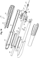
- FIG. 2-9 One example of a deployment handle that may be used with a delivery device for the controlled and sequential deployment of a stent graft is illustrated in Figures 2-9 , identified herein as a "pull-back" deployment handle assembly 200.
- An alternative example of a deployment handle assembly is illustrated in Figures 1 , 10-14 , identified herein as a "rotational" deployment handle assembly 100.
- the pull-back deployment handle assembly 200 is located at the distal end of the device and is intended to remain outside of the patient during a procedure.
- the handle is actuated by the physician to release a prosthesis from the proximal end 600 of the delivery device. Any portion of the handle and its various components may be provided with gripping features that provide secure and/or ergonomic gripping by the physician and provide the physician with tactile feedback while gripping and/or operating the handle.
- Figures 2-9 illustrate the pull back deployment handle assembly 200 as it is operated by a user to sequentially release the proximal and distal ends of a prosthesis, such as a stent graft.
- the first handle 205 is a stationary proximal handle that allows the physician to grip and stabilize the delivery device.
- the second handle 210 is distal to the first handle and is actuated by the physician during deployment of the prosthesis.
- the pull back deployment handle assembly 200 further includes a locking mechanism 250 that is shown in Figure 9 .
- This locking mechanism 250 is disposed about the surface of the first handle 205 and prevents unintended or premature movement of the second handle 210 relative to the first handle 205.
- the locking mechanism 250 may engage the first handle 205 through latching or other engagement, including, but not limited to a pin, a clip and the like.
- the first handle 205 is disposed at the proximal end of handle assembly 200 and about the distal end of a sheath 320.
- the first handle 205 extends the length of the deployment handle assembly 200 and defines a generally tubular interior space that houses other components of the handle assembly.
- the second handle 210 is partially disposed about the distal end of the first handle 205.
- the sheath 320 is at least partially withdrawn to expose a proximal portion of the prosthesis carried at the proximal end 600 of the device and, after the proximal end of the prosthesis is released, further pull back of the second handle 210 ( Figure 6 ) to a third position further withdraw the sheath 320 to release the distal end of the prosthesis.
- the second handle 210 is engageable with the distal end of a handle rear inner 215 such that retraction of the second handle 210 in a distal direction also retracts the handle rear inner 215 relative to the first handle 205.
- the handle rear inner 215 is initially positioned within the first handle 205 and is distally slidable relative to the first handle 205.
- the proximal end of the handle rear inner 215 is attached to the sheath 320 at the sheath connector 245.
- the handle rear inner 215 has a body slot 217 that extends along one side of the handle rear inner 215.
- the body slot 217 provides a track for a tab 207 that protrudes from an inner surface of the first handle 205 and prevents rotational movement of the handle rear inner 215.
- the proximal end 219 of the slot 217 limits the distal-most position of the handle rear inner 215 while the distal end 218 of the slot 217 limits the proximal most position of the handle rear inner 215.
- the handle rear inner 215 further includes a proximal lip 216 that limits the distal movement of the handle rear inner 215 and the attached second handle 210 when the proximal lip 216 encounters and/or abuts the proximal end of the rotary dial 220. Distal movement of the handle rear inner 215 is restricted until, as discussed below, the rotary collar 225 is fully rotated.
- the rotary collar 225 is disposed about the handle rear inner 215.
- the proximal end of the rotary collar 225 can rotate about the distal end of the rotary dial 220.
- threading 224 of the rotary dial 220 engages the collar threading 227 located at the proximal end of the rotary collar 225.
- gear engaging teeth 226 on the inside surface of the rotary collar 225 engage with rotation gears 255 to rotate the inner cannula 310 to release the proximal end of the prosthesis.
- the rotary dial 220 serves to limit the movement of the handle rear inner 215 and prevent the continued withdrawal of the sheath 320 until the rotary collar 225 has been fully rotated.
- the rotary dial 220 is, as noted above, located proximal to the rotary collar 225 and is also disposed about the handle rear inner 215.
- the rotary dial 220 includes a movement slot 221 and an engagement slot 222.
- the movement slot 221 extends from the proximal end of the rotary dial 220 and allows the rotary dial 220 to receive the tab 207 protruding from the inner surface of the first handle 205.
- the engagement slot 222 is located at the distal end of the rotary dial 220 and serves to lock the rotary dial 220 in place when tab 207 is rotated to fit into and engage slot 222.
- the inner cannula 310 extends from the distal end of the handle assembly 200 to the proximal end 600 of the delivery device.
- a guide wire flush port 230 is located at the distal end of the inner cannula 310 and provides access to the guide wire flush tube (not shown) that is disposed about the cannula 310 and is connected to the positioner 330.
- the positioner 330 is disposed about the inner cannula 310 and extends proximally from the rotation gears.
- the sheath 320 is at least partially disposed about the positioner 330 and is distally moveable relative to the positioner 330.
- the positioner 330 includes an attachment slot 331 that is configured to receive the tab 207 to retain the positioner 330 in a stationary position.
- the sheath 320 extends from the proximal end 600 of the delivery device to the proximal end of the first handle 205.
- the proximal end of the handle rear inner 215 is attached to the distal end of the sheath 320 at sheath connector 245.
- the sheath connector 245 provides access to the sheath 320 for the positioner 330 and the sheath flush tube 235.
- the sheath flush tube 235 connects the sheath flush port 240 to the sheath connector 245.
- the sheath flush port 240 is flushed with saline when the delivery device is introduced into the patient's body.
- the rotation gears 255 facilitate rotation of the inner cannula 310 through rotation of the rotary collar 225. As shown in Figure 9 , the rotation gears 255 are attached to the distal end of the positioner 330. A cross section of the rotation gears 255 is shown in Figures 7-8 .
- the rotation gears 255 include a first gear 256 and a second gear 257.
- the rotation gears 255 are retained between two disks: a proximal disk 259 is attached to the base of the positioner 330 and a distal disk 258 forms the distal end of the rotation gears 255.
- the proximal disk 259 and the distal disk 258 have openings that accommodate the inner cannula 310 and the sheath flush port 240.
- a rotation gear retention slot 260 extends between the proximal disk 259 and distal disk 258 to form a slot for the retention of the first gear 256.
- the first gear 256 is disposed about and is attached to the inner cannula 310.
- the second gear 257 is contained between the slot 217 of the handle rear inner 215 and the teeth of the first gear 256.
- the gear engaging teeth 226 of the rotary collar 225 engage the teeth of the second gear 257 to cause rotation of the second gear 257 in a first direction.
- the second gear 257 interacts with the teeth of the first gear 256 to cause the first gear 256 to rotate, thus imparting rotation to the inner cannula.
- a delivery device may be initially flushed with saline through the flush port 240.
- a guide wire may then be introduced into the device though the distal end, allowing the device to be introduced into a patient's vasculature and tracked to a desired location.
- Figure 3 shows the deployment handle assembly 200 after the delivery device has been introduced into the patient's body and before any deployment steps have been performed. At this time, any locking mechanism and/or safety latch 250 or other mechanism can be operated to "unlock" the handle assembly 200 to allow the handle assembly to be operated and a prosthesis deployment sequence to commence.
- the second handle 210 is pulled back in a distal direction along the outer surface of the first handle 205 as indicated by the arrow shown in Figure 4 .
- the physician places one hand (e.g., a "non-dominant" hand) on the front or first handle 205 and a second hand (e.g., a "dominant” hand) on the rear or second handle 210.
- the physician slowly pulls the second handle 210 in the distal direction with one hand as indicated by the arrow in Figure 4 , while the other hand gripping the first handle 205 stabilizes the device.
- the positioner 330 preferably has sufficient rigidity and/or stiffness to resist buckling as the sheath 320 is retracted distally over it.
- the handle rear inner 215 moves distally as the second handle 210 is pulled back until the proximal lip 216 on the handle rear inner 215 hits the proximal end of the rotary dial 220, which prevents further distal movement of the handle rear inner 215 at this stage of deployment. This prevents the premature release of the distal attachment of the prosthesis.
- the proximal lip 216 encounters the proximal end of the rotary dial 220, the second handle 210 is pulled back a sufficient distance to expose the rotary collar 225 as shown in Figure 4 .
- the rotary collar 225 is now accessible to the physician and can be manually rotated. As previously mentioned, rotation of the rotary collar 225 imparts rotation to the rotation gears 255 as illustrated in Figure 7 . As described above, the gear engaging teeth 226 of the rotary collar 225 engage with the teeth of the second gear 257 to cause the second gear 257 to turn in a counter-clockwise direction as the rotary collar 225 is rotated in a counter-clockwise direction. The second gear 257 then interacts with the gears of the first gear 256, causing the first gear 256 to rotate in a clockwise direction which imparts rotation to the attached cannula 310.
- this rotation of the inner cannula 310 releases the proximal end of the prosthesis.
- the physician cannot further pull back the second handle 210 to release of the distal end of the prosthesis, thus preventing the various steps of deployment from being performed out of a preferred sequence.
- the collar threading 227 located at the proximal end of the rotary collar 225 is disposed about the dial threading 224 located at the distal end of the rotary dial 220.
- the respective threading 227, 224 permits a selected number of rotations of the rotary collar 225 around the rotary dial 220 while the rotary dial 220 remains stationary.
- the selected number of rotations imparted to the rotary collar 225 is preferably the number of rotations required to release the proximal end of the prosthesis.
- the rotary collar 225 When the rotary collar 225 has been sufficiently rotated about the rotary dial 220 such that release of the proximal end of the prosthesis has been achieved, the rotary collar 225 can then be further rotated (e.g., one additional/final rotation) which imparts rotation to the rotary dial 220. This causes tab 207 to be released from the engagement slot 222 of the rotary dial 220 and move into the slot 221 of the rotary dial 220. In addition, the tab 223 on the proximal end of the rotary dial 220 is rotated into the rotary collar movement slot 206 of the first handle 205.
- This final rotation of the rotary collar 225 engages the rotary collar 225 with the rotary dial 220 and allows both the rotary collar 225 and the rotary dial 220 to be pulled back in a distal direction with the second handle 210 as shown in Figure 6 .
- the physician can now further pull back the second handle 210 to further retract the sheath 320 in a distal direction as shown by the arrow in Figure 6 .
- the second handle 210 As the second handle 210 is pulled back, it also moves the handle rear inner 215 in a distal direction.
- the proximal lip 216 of the handle rear inner 215 engages the proximal end of the rotary dial 220 to also move the rotary dial 220 and the rotary collar 225 together in a distal direction.
- the rotary dial 220 is prevented from being entirely withdrawn out of the first handle 205 because tab 223 protruding from the rotary dial 220 is engaged with movement slot 206 ( Figure 9 ) formed in the distal end of the first handle 205.
- Figures 22-23 illustrate the release of the prosthesis as the second handle 210 is further pulled back as shown in Figure 6 . Specifically, pulling back further on the second handle 210 exposes the distal end of the prosthesis.
- the simultaneous withdrawal of the rotary dial 220 with the second handle 210 withdraws the cannula 310 distally from the body of the prosthesis and the withdrawal of the rotary collar 225 withdraws the trigger wire 790 from the distal end of the prosthesis to thereby release the prosthesis from the delivery device and deploy it within the body at the desired deployment site.
- Figures 1 and 10-14 illustrate the rotational deployment handle assembly 100 as it is operated by a user to release the proximal and distal ends of a prosthesis, such as a stent graft from the delivery device.
- the rotational deployment handle assembly 100 differs from the pull back handle assembly 200 in that the second handle 120 is moved distally relative to the first handle 110 by axial rotation of the second handle 120.
- the rotational deployment handle assembly 100 remains outside of the patient during a delivery and deployment procedure.
- the various components of the handle assembly 100 can be actuated by the physician to release the prosthesis from the proximal end of the delivery device.
- the rotational deployment handle 100 includes a front or first handle 110 and a rear or second handle 120.
- the handle assembly 100 also preferably includes a locking mechanism 180 that is shown in Figure 14 which may engage the first handle 110 through a latching or other engagement, such as a pin, clip and others known to one of skill in the art.
- This locking mechanism 180 is configured to prevent the second handle 120 from rotating relative to the first handle 110, thereby preventing unintended or premature deployment of any portion of the prosthesis.
- the first handle 110 provides the physician a consistent point of reference for the prosthesis and allows the physician to grip and stabilize the device during a procedure.
- the proximal end of the first handle 110 is disposed about the distal end of the sheath 320.
- the first handle 110 is a generally tubular structure that forms an interior space that serves generally as a housing for various components of the handle assembly 100.
- the first handle 110 has a slot 112 that allows the teeth 131 of a shuttle 130 to protrude through the surface of the first handle 110.
- a tab 111 protrudes from the inner surface of the distal end of the first handle 110. This tab 111 engages with the distal end of the positioner 330 to keep the positioner 330 stationary as the prosthesis is deployed.
- the second handle 120 of the rotational deployment handle assembly 100 is disposed about the distal end of the first handle 110 and is actuated by manual rotation by the user.
- the inner surface of the second handle 120 comprises threading 121 that engages the teeth 131 of the shuttle 130.
- rotation of the second handle 120 engages the shuttle 130 and advances the shuttle 130 in a distal direction along the positioner 330.
- the shuttle 130 is attached at the proximal end 133 to the sheath 320 and is disposed about the positioner 330. As the shuttle 130 moves distally along the positioner 330, it pulls the sheath 320 distally along the positioner 330.
- the body of the shuttle 130 has a slot 132 that extends longitudinally along one side of the shuttle 130.
- the slot 132 provides a track for the tab 111 that extends from the inner surface of the first handle 110 and prevents rotational movement of the shuttle 130 as it moves distally along the length of the positioner 330.
- the proximal end 133 of the shuttle slot 132 limits the distal most position of the shuttle 130.
- a rotary dial 150 having a distal end and a proximal end 153 is disposed about the distal end of the positioner 330.
- the rotary dial 150 provides rotational control of the inner cannula 310.
- a rotary cog 140 is located at the base of the positioner 330 and is attached to the inner cannula 310.
- the proximal end 153 of the rotary dial 150 forms a slot 152 that is disposed about the rotary cog 140.
- a slot at the proximal end 153 of the rotary dial 150 engages the tab 111 of the first handle 110 to only allow the rotary dial 150 to move in a distal direction while tab 111 is engaged within the slot 153.
- the rotary dial 150 is then positioned such that it is disposed about the rotary cog 140 such that rotation of the rotary dial 150 causes the rotary cog 140 (and the connected inner cannula 310) to rotate as well. Further, as will be described below, the distal end of the trigger wire 790 of Figures 19-22 is attached to the rotary dial 150, such that distal movement of the rotary dial 150 retracts the trigger wire 790 to release the distal end of the prosthesis.
- a collar 160 retained within the distal end of the first handle limits the movement of the shuttle 130 by preventing the second handle 120 from rotating before the rotary dial 150 is fully rotated.
- the collar 160 has a retention tab 161 on either side of the collar 160 that is retained in a slot 112 of the first handle 110 that prevents the collar 160 from rotating.
- the inner surface of the collar 160 has inside threads 163 that can engage with the rotary dial threading 151 of the rotary dial 150. As will be described more fully below, rotation of the rotary dial 150 engages the rotary dial threading 151 with the inside threads 163 of the collar 160 and advances the collar 160 in a proximal direction.
- the collar 160 also has a top opening 162 that is sufficiently wide to allow the teeth 131 to move past the collar 160.
- the inner cannula 310 extends from the distal end of the rotational deployment handle assembly 100 to the proximal end 600 of the delivery device.
- the flushing port 170 is located at the distal end of the inner cannula 310 and provides access to the flushing tube (not shown) that is disposed about the inner cannula 310.
- the flushing tube is attached to the positioner 330 and allows both the inner cannula 310 and the sheath 320 to be flushed with saline as the delivery device is introduced into the body.
- the sheath 320 is disposed about the prosthesis that is releasably retained at the proximal end 600 of the delivery device.
- the sheath extends along the length of the device and is attached to the shuttle 130 at its distal end, such that distal movement of the shuttle 130 causes the sheath 320 to be retracted.
- a delivery device may be initially flushed with saline through the flush port 170.
- a guide wire may then be introduced into the device though the distal end, allowing the device to be introduced into a patient's vasculature and tracked to a desired location.
- Figure 10 shows the deployment handle assembly 100 after the delivery device has been introduced into the patient's body and before any deployment steps have been performed. At this time, any safety latch 180 or other mechanism can be operated to "unlock" the handle assembly 100 to allow the handle assembly to be operated and a prosthesis deployment sequence to commence.
- the physician places one hand on the first handle 110 and a second hand on the second handle 120.
- the physician slowly rotates the second handle 120 which causes the teeth 131 of the shuttle 130 to engage the threading 121 of the second handle 120 to move the shuttle 130 in a distal direction, thus unsheathing at least a proximal end of the prosthesis.
- the positioner 330 has sufficient rigidity/stiffness to resist buckling of the positioner 330 as the sheath 320 is withdrawn over it.
- the distal end of the shuttle 130 moves distally so that it is disposed over the proximal end of the rotary dial 150 as illustrated in Figure 11 .
- the rotary dial 150 may then be manually rotated by the physician to release the proximal end of the prosthesis.
- the proximal end 153 of the rotary dial 150 is disposed about the rotary cog 140 such that rotation of the rotary dial 150 causes the rotary cog 140 and the attached cannula 310 to rotate.
- the inside threads 163 of the collar 160 engages the threading 151 on the rotary dial 150.
- the respective threads 163, 151 are configured to allow a selected number of rotations of the rotary dial.
- the number of rotations permitted by the respective threading 163, 151 is the number of rotations required to release the proximal end of the prosthesis.
- the physician cannot further rotate the second handle 120 to withdraw the shuttle 130 (and the attached sheath 320) further to release the distal end of the prosthesis.
- the second handle 120 can then be further rotated to continue withdrawing the shuttle 130 distally from the first handle 110 and to retract the sheath 320 in a distal direction.
- the second handle 120 As the second handle 120 is further rotated, it also moves the rotary dial 150 in a distal direction.
- the shuttle 130 is prevented from being entirely withdrawn from the first handle 110 by the proximal end 133 of the shuttle slot 132 which engages the tab 111 of the first handle 110.
- Figures 22-23 show the release of the prosthesis as the second handle 120 is further rotated.
- the rotation of the second handle 120 exposes the distal end of the prosthesis.
- the simultaneous withdrawal of the rotary dial 150 withdraws the trigger wire 790 from the distal end of the prosthesis, which then releases the prosthesis in the body at the location of the deployment site.
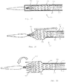
- Figures 15 and 16 illustrate a proximal portion of the delivery device 600, and in particular, one example of an attachment and release mechanism for the proximal end of a prosthesis that can be operated using the delivery handle assemblies 100, 200 described above.
- Figure 15 shows a tapered nose cone 615 having a proximal tip 620 at the proximal end of the inner cannula 310.
- Nose cone 615 has a reverse distal taper 625 at its distal end 630.
- the nose cone surface 640 presents a smooth tapered surface to facilitate entry into and movement through a body vessel.
- An exemplary attachment and release mechanism 635 is disposed at or near the distal end 630 of the nose cone 615 and on the inner cannula 310.
- the attachment and release mechanism 635 comprises coiled member 645 having a proximal end 650, a distal end 655, and a plurality of turns 660 disposed there between.
- the proximal end 650 of the coiled member 645 is secured to the outer surface 675 of the cannula 310 using a suitable attachment mechanism, such as a solder, weld, mechanical attachment, friction fit, crimp, or combination of these or other techniques. Accordingly, the proximal end 650 of the coiled member 645 cannot move relative to the outer surface 675 of the inner cannula 310.
- the proximal end 650 of the coiled member 645 comprises a first diameter d 1, which may be approximately the same diameter, or slightly greater than, an outer diameter of the cannula 310.
- the distal end 655 of the coiled member 645 is unsecured relative to the outer surface 675 of the inner cannula 310, as shown in Figure 16 .
- the distal end 655 of the coiled member 645 may comprise a second diameter d 2 which is greater than the first diameter d 1 of the proximal end 650 of the coiled member 645.
- the plurality of turns 660 are divided into a proximal series of turns 665, which have the first diameter d 1, and a distal series of turns 670, which have the second diameter d 2.
- the proximal series of turns 665 may be disposed in close proximity or abutting one another, as depicted in Figure 16 .
- the distal series of turns 670 may be spaced apart from one another a greater distance than the proximal series of turns 665.
- the distal series of turns 670 are spaced apart a predetermined distance denoted by spacing 685.
- prosthesis such as stent graft 700
- Stent graft 700 includes, in this example, a graft material 706, a bare proximal top stent 740 (though the disclosure is not so limited), and one or more stents 750 attached to the graft material 730.
- the stents 750 may be on either or both inner and outer surfaces of the tube of graft material 730 and may have the characteristics of self-expanding stents, balloon expanding stents, or both, depending on the desired stent characteristics.
- the stent graft 700 has an uncoupled state in which the stent graft 700 is positioned coaxially over the inner cannula 310 with the proximal end 710 of the stent graft 700 in longitudinal proximity relative to the distal end of the coiled member 645, as shown in Figure 18 .
- one or more loops 760 that are coupled to the proximal apices 770 of the stent 740 are threaded around the distal end of the coiled member 645 one at a time, preferably until all of the loops 760 are coupled to the coiled member 645.
- Such coupling may be achieved by rotating the inner cannula 310 in a clockwise direction until the proximal end 710 of the stent 740 is sufficiently compressed in a radially inward direction, as depicted in Figure 17 .
- a gap 680 between the distal end of the coiled member 645 and the outer surface of the inner cannula 310 permits positioning of the loops 760 in the series of turns at the distal end of the coiled member 645.
- the loops 760 are further accommodated within a spacing between the distal series of turns.
- the loops 760 preferably are coupled to the coiled member 645 in a manner in which at least one loop 760 is positioned around at least one full turn of the distal series of turns, and preferably around at least 1.5 turns at the distal end 655 of the coiled member 645, thereby reducing the likelihood of inadvertent uncoupling of the loops 760 from the coiled member 645.
- the coupling shown in Figure 16 secures the stent 740 to the cannula 310 via the coiled member 645 in a manner that may subsequently facilitate insertion of the subassembly comprising the inner cannula 310 and the stent graft 700 into an outer sheath, such as sheath 320 described above.
- the outer sheath 320 is configured to radially restrain other regions of the stent graft 700 for delivery to a target site within a patient's anatomy.
- the loops 760 may be coupled to every other proximal apex 770 as shown in Figure 17 to restrain the stent 740 during delivery.
- the loops 760 are not coupled to the second proximal apices 780, which may comprise barbs.
- the adjacent second proximal apices 780 also may be indirectly pulled in a radially inward direction during delivery.
- the configuration of the stent 740 facilitates the indirect compression of the adjacent second proximal apices 780. Since only selected ones of the proximal apices are restrained during delivery, the number of loops 760 may be reduced.
- Figures 19-23 illustrate the controlled and sequential release of the stent graft from the delivery device using the handle assemblies 100, 200 described herein. More particularly, Figure 19 shows the stent graft 700 loaded on the delivery device and compressed by the sheath 320. In operation, the operator withdraws the sheath 320 in the direction indicated by the arrow shown in Figure 20 . This may be accomplished by pulling back on the second handle 210 of handle assembly 200 and/or by rotating second handle 120 of handle assembly 100 to move it in a distal direction, thus withdrawing the sheath 320.
- the inner cannula 310 may be rotated in a counter-clockwise direction (as shown by the arrow in Figure 21 ) until the loops 760 are uncoupled from the coiled member 645, i.e., in a reverse manner from which the loops 760 were coupled to the coiled member 645.
- Rotation of the inner cannula 310 may be accomplished as described in detail above, such as by rotating rotary collar 225 of handle assembly 200 and/or rotating rotary dial 150 of handle assembly 100.
- the proximal stent 740 then may be deployed as shown in Figures 17, 18 , and 21 .
- the remainder of the stent graft 700 may be deployed by further actuation of the handle assembly 100 and/or 200.
- further retraction of the sheath 320 as shown by the arrows in Figures 20 , 22 and 23
- actuation of any other mechanisms such as trigger wires
- Figures 22-23 illustrate the release of the distal end of the stent graft 700 by retracting the sheath 320 and releasing the trigger wire 790.
- further retraction of the sheath and trigger wire release may be accomplished by further manipulating handle assembly 100 and/or 200, such as by moving the second handle 120, 210 further in a distal direction (whether by rotation of 120 or pulling back on 210.
- the proximal end of the stent 740 is radially restrained without the use of conventional trigger wires that span a full longitudinal length of the delivery system. Accordingly, the radial profile of the delivery system may be reduced, thereby reducing packing density of the system. Moreover, deployment may be simplified as reduced deployment forces are expected to be needed relative to the use of conventional trigger wires. As a further advantage, deployment of a stent using the described device comprising at least one coiled member may allow for more precise positioning of the stent. In particular, deployment using the coiled member may provide a more controlled unwinding of the associated portion of the stent.
- a prosthesis delivery device comprising:
- the second handle slides distally from the first position to the second position.
- the second handle is axially rotated distally to move the second handle from the first position to the second position.
- the rotary dial is covered by the second handle when the second handle is in the first position and the rotary dial is exposed when the second handle is in the second position.
- the prosthesis comprises a stent graft having a stent at the proximal end of the stent graft and the stent comprises a series of proximal apices.
- the proximal end of the inner cannula comprises a coil that releasably engages one or more of the stent proximal apices.
- rotation of the rotary dial imparts rotation to the inner cannula to thereby release a proximal end of the prosthesis from the inner cannula.
- the prosthesis delivery device further comprises at least one trigger wire, wherein a proximal end of the trigger wire is releasably engaged with a distal end of the prosthesis and a distal end of the trigger wire is secured to the handle assembly.
- the second handle is further distally moveable from the second position to a third position and movement of the handle to the third position retracts the trigger wire and releases the distal end of the prosthesis from the inner cannula.
- the handle assembly further comprises a safety mechanism configured to prevent the inadvertent movement of the second handle.
- the prosthesis delivery device further comprises a rotary gear system disposed within the rotary dial and the rotary gear system is configured to impart rotation to the inner cannula when the rotary dial is rotated.
- the gear system comprises a first gear and second gear, the second gear being secured to the rotatable inner cannula, and rotation of the rotary dial imparts rotation to the first gear and the first gear imparts rotation to the second gear to thereby rotate the inner cannula.
- the rotary dial and the first gear have a 1:3 gearing ratio.
- a method for sequentially releasing a prosthesis from a delivery device comprising a rotatable inner cannula extending from a proximal end to a distal end; a prosthesis releasably coupled to the proximal end of the inner cannula; a sheath coaxially disposed about at least a portion of the prosthesis; a delivery handle assembly at a distal end of the delivery device, the delivery handle assembly comprising, a first handle disposed about the inner cannula, wherein the first handle comprises a rotary dial rotatably disposed about a distal end of the first handle; a second handle disposed about at least a portion of the distal end of the first handle, the method comprising:
- the prosthesis comprises a stent graft having a stent at the proximal end thereof and the proximal end of the inner cannula comprises a coil that is releasably engaged with one or more proximal apices of the stent; wherein rotation of the rotary dial preferably imparts rotation to the inner cannula to release the coils at the proximal end of the inner cannula from the proximal stent apices.
Landscapes
- Health & Medical Sciences (AREA)
- Engineering & Computer Science (AREA)
- Biomedical Technology (AREA)
- Cardiology (AREA)
- Oral & Maxillofacial Surgery (AREA)
- Transplantation (AREA)
- Heart & Thoracic Surgery (AREA)
- Vascular Medicine (AREA)
- Life Sciences & Earth Sciences (AREA)
- Animal Behavior & Ethology (AREA)
- General Health & Medical Sciences (AREA)
- Public Health (AREA)
- Veterinary Medicine (AREA)
- Media Introduction/Drainage Providing Device (AREA)
- Prostheses (AREA)
Description
- The present invention relates to delivery devices for prostheses, such as stents, grafts and stent grafts (collectively prostheses) in the vascular system of a patient. Embodiments relate to a delivery device having a handle that permits controlled and sequential release and deployment of a prosthesis from the delivery device.
-
US 5,776,142 discloses a controllable stent delivery system and method. - According to an aspect of the invention, there is provided a prosthesis delivery device as in claim 1.
- A prosthesis delivery device is disclosed. The delivery device comprises a proximal end and a distal end and a rotatable inner cannula extending from the proximal end to the distal end. A prosthesis is releasably coupled to the proximal end of the inner cannula and a sheath is coaxial with the inner cannula and extends at least partially between the proximal and distal ends of the inner cannula. A delivery handle assembly is located at the distal end of the delivery device. In one example, the delivery handle assembly comprises a first or front handle disposed about the inner cannula, wherein the first handle comprises a rotary dial rotatably disposed about a distal end thereof and a second handle disposed about at least a portion of the distal end of the first handle, wherein the second handle is longitudinally moveable relative to the first handle between a first position and a second position. When the second handle is in the first position, the sheath is coaxially disposed about the prosthesis and rotation of the dial is prevented, and when the second handle, is in the second position the sheath is retracted distally to expose at least a portion of the prosthesis and rotation of the dial is permitted.
- In one example, second handle slides distally from the first position to the second position. In another example, the second handle is axially rotated distally to move the second handle from the first position to the second position.
- In another example, a method for sequentially releasing a prosthesis from a delivery device is disclosed. The method comprises the steps of actuating the second handle from a first position to a second position to retract the sheath to expose at least a portion of the prosthesis, rotating the rotary dial to release the proximal end of the prosthesis and actuating the second handle from a second position to a third position to release a distal end of the prosthesis.
- Embodiments of the invention are described below, by way of example only, with reference to the accompanying drawings.
-
Figure 1 is a rear perspective view of one example of a handle assembly of a prosthesis delivery device. -
Figure 2 is a rear perspective view of another example of a handle assembly of a prosthesis delivery device. -
Figure 3 is a partial sectional view of the prosthesis delivery device ofFigure 2 . -
Figure 4 is a partial sectional view of the prosthesis delivery device ofFigure 2 during deployment of a prosthesis. -
Figure 5 is a partial sectional view of the prosthesis delivery device ofFigure 2 during deployment of a prosthesis. -
Figure 6 is a partial sectional view of the prosthesis delivery device ofFigure 2 during deployment of a prosthesis. -
Figure 7 is a cross-sectional view of the gear system in the handle of the delivery device ofFigure 2 at one stage of deployment of a prosthesis. -
Figure 8 is a cross-sectional view of the gear system in the handle of the delivery device ofFigure 2 at another stage of deployment of a prosthesis. -
Figure 9 is an exploded view of a prosthesis delivery device ofFigure 2 . -
Figure 10 is a partial sectional view of the prosthesis delivery device ofFigure 1 . -
Figure 11 is a partial sectional view of the prosthesis delivery device ofFigure 1 during deployment of a prosthesis. -
Figure 12 is a partial sectional view of the prosthesis delivery device ofFigure 1 during deployment of a prosthesis. -
Figure 13 is a partial sectional view of the prosthesis delivery device ofFigure 1 during deployment of a prosthesis. -
Figure 14 is an exploded view of the prosthesis delivery device ofFigure 1 . -
Figure 15 is a partial side view of a proximal end of a prosthesis delivery device ofFigures 1 and 2 with an exemplary prosthesis proximal stent attachment and release mechanism. -
Figure 16 is an enlarged partial side view of the proximal stent attachment and release mechanism ofFigure 15 . -
Figure 17 is a partial side view of a delivery device having a prosthesis carried on the proximal end thereof with a proximal stent attached to the attachment and release mechanism. -
Figure 18 illustrates the delivery device ofFigure 17 with the proximal stent released from the attachment and release mechanism. -
Figures 19-23 illustrate one example of a method for releasing a prosthesis from a delivery device. - The embodiments described in this disclosure will be discussed generally in relation to deployment of prostheses, such as stents, grafts and stent grafts into the aorta, but the disclosure is not so limited and may be applied to other areas of the vasculature or other body vessels or lumens.
- In the present application, the term "proximal" refers to a direction that is generally closest to the heart during a medical procedure, while the term "distal" refers to a direction that is furthest from the heart during a medical procedure.
- The term "stent graft" refers to a device that has a tubular body of biocompatible graft material and at least one stent fastened to the tubular body to define a lumen through the stent graft. The stent graft may be bifurcated and/or may include fenestrations, side arms, or the like. Other arrangements of stent grafts also are within the scope of this disclosure.
- The delivery device described herein facilitates the delivery and deployment of a prosthesis at an implantation site within a body vessel. The handle assembly preferably comprises mechanisms to prevent a physician from performing deployment steps out of sequence while helping to ensure that all deployment steps are completed. Particularly, the handle assembly is designed to allow the physician the ability to perform only one deployment step at a time, and until one step is completed, the next deployment step cannot be initiated and/or performed.
- In one non-limiting example, the handle assembly may be configured to facilitate deployment of a bifurcated stent graft in the aorta in a preferred sequence including partial sheath withdrawal to expose the proximal stent and contralateral stent limb, followed by deployment of the proximal stent, further sheath withdrawal to expose the ipsilateral limb and finally trigger wire release to facilitate deployment of the distal end of the stent graft.
- One example of a deployment handle that may be used with a delivery device for the controlled and sequential deployment of a stent graft is illustrated in
Figures 2-9 , identified herein as a "pull-back"deployment handle assembly 200. An alternative example of a deployment handle assembly is illustrated inFigures 1 ,10-14 , identified herein as a "rotational"deployment handle assembly 100. - The pull-back
deployment handle assembly 200 is located at the distal end of the device and is intended to remain outside of the patient during a procedure. The handle is actuated by the physician to release a prosthesis from theproximal end 600 of the delivery device. Any portion of the handle and its various components may be provided with gripping features that provide secure and/or ergonomic gripping by the physician and provide the physician with tactile feedback while gripping and/or operating the handle. -
Figures 2-9 illustrate the pull backdeployment handle assembly 200 as it is operated by a user to sequentially release the proximal and distal ends of a prosthesis, such as a stent graft. In operation, thefirst handle 205 is a stationary proximal handle that allows the physician to grip and stabilize the delivery device. Thesecond handle 210 is distal to the first handle and is actuated by the physician during deployment of the prosthesis. - The pull back
deployment handle assembly 200 further includes alocking mechanism 250 that is shown inFigure 9 . Thislocking mechanism 250 is disposed about the surface of thefirst handle 205 and prevents unintended or premature movement of thesecond handle 210 relative to thefirst handle 205. Thelocking mechanism 250 may engage thefirst handle 205 through latching or other engagement, including, but not limited to a pin, a clip and the like. - As illustrated in
Figure 3 , thefirst handle 205 is disposed at the proximal end ofhandle assembly 200 and about the distal end of asheath 320. Thefirst handle 205 extends the length of thedeployment handle assembly 200 and defines a generally tubular interior space that houses other components of the handle assembly. Thesecond handle 210 is partially disposed about the distal end of thefirst handle 205. When thesecond handle 210 is pulled distally from a first position (Figure 3 ) to a second position (Figure 4 ) thesheath 320 is at least partially withdrawn to expose a proximal portion of the prosthesis carried at theproximal end 600 of the device and, after the proximal end of the prosthesis is released, further pull back of the second handle 210 (Figure 6 ) to a third position further withdraw thesheath 320 to release the distal end of the prosthesis. - To accomplish this, the
second handle 210 is engageable with the distal end of a handle rear inner 215 such that retraction of thesecond handle 210 in a distal direction also retracts the handle rear inner 215 relative to thefirst handle 205. As shown inFigure 3 , the handle rear inner 215 is initially positioned within thefirst handle 205 and is distally slidable relative to thefirst handle 205. The proximal end of the handle rear inner 215 is attached to thesheath 320 at thesheath connector 245. The handle rear inner 215 has abody slot 217 that extends along one side of the handle rear inner 215. Thebody slot 217 provides a track for atab 207 that protrudes from an inner surface of thefirst handle 205 and prevents rotational movement of the handle rear inner 215. Theproximal end 219 of theslot 217 limits the distal-most position of the handle rear inner 215 while thedistal end 218 of theslot 217 limits the proximal most position of the handle rear inner 215. The handle rear inner 215 further includes aproximal lip 216 that limits the distal movement of the handle rear inner 215 and the attachedsecond handle 210 when theproximal lip 216 encounters and/or abuts the proximal end of therotary dial 220. Distal movement of the handle rear inner 215 is restricted until, as discussed below, therotary collar 225 is fully rotated. - The
rotary collar 225 is disposed about the handle rear inner 215. The proximal end of therotary collar 225 can rotate about the distal end of therotary dial 220. Specifically, as shown inFigure 4 , threading 224 of therotary dial 220 engages the collar threading 227 located at the proximal end of therotary collar 225. When therotary collar 225 is rotated,gear engaging teeth 226 on the inside surface of therotary collar 225 engage with rotation gears 255 to rotate theinner cannula 310 to release the proximal end of the prosthesis. - The
rotary dial 220 serves to limit the movement of the handle rear inner 215 and prevent the continued withdrawal of thesheath 320 until therotary collar 225 has been fully rotated. Therotary dial 220 is, as noted above, located proximal to therotary collar 225 and is also disposed about the handle rear inner 215. Therotary dial 220 includes amovement slot 221 and anengagement slot 222. Themovement slot 221 extends from the proximal end of therotary dial 220 and allows therotary dial 220 to receive thetab 207 protruding from the inner surface of thefirst handle 205. Theengagement slot 222 is located at the distal end of therotary dial 220 and serves to lock therotary dial 220 in place whentab 207 is rotated to fit into and engageslot 222. Theinner cannula 310 extends from the distal end of thehandle assembly 200 to theproximal end 600 of the delivery device. A guide wireflush port 230 is located at the distal end of theinner cannula 310 and provides access to the guide wire flush tube (not shown) that is disposed about thecannula 310 and is connected to thepositioner 330. - As shown in
Figure 9 , thepositioner 330 is disposed about theinner cannula 310 and extends proximally from the rotation gears. Thesheath 320 is at least partially disposed about thepositioner 330 and is distally moveable relative to thepositioner 330. Thepositioner 330 includes anattachment slot 331 that is configured to receive thetab 207 to retain thepositioner 330 in a stationary position. - The
sheath 320 extends from theproximal end 600 of the delivery device to the proximal end of thefirst handle 205. The proximal end of the handle rear inner 215 is attached to the distal end of thesheath 320 atsheath connector 245. Thesheath connector 245 provides access to thesheath 320 for thepositioner 330 and the sheathflush tube 235. The sheathflush tube 235 connects the sheathflush port 240 to thesheath connector 245. The sheathflush port 240 is flushed with saline when the delivery device is introduced into the patient's body. - The rotation gears 255 facilitate rotation of the
inner cannula 310 through rotation of therotary collar 225. As shown inFigure 9 , the rotation gears 255 are attached to the distal end of thepositioner 330. A cross section of the rotation gears 255 is shown inFigures 7-8 . The rotation gears 255 include afirst gear 256 and asecond gear 257. The rotation gears 255 are retained between two disks: aproximal disk 259 is attached to the base of thepositioner 330 and adistal disk 258 forms the distal end of the rotation gears 255. Theproximal disk 259 and thedistal disk 258 have openings that accommodate theinner cannula 310 and the sheathflush port 240. A rotationgear retention slot 260 extends between theproximal disk 259 anddistal disk 258 to form a slot for the retention of thefirst gear 256. Thefirst gear 256 is disposed about and is attached to theinner cannula 310. Thesecond gear 257 is contained between theslot 217 of the handle rear inner 215 and the teeth of thefirst gear 256. As will be described in more detail below, thegear engaging teeth 226 of therotary collar 225 engage the teeth of thesecond gear 257 to cause rotation of thesecond gear 257 in a first direction. Thesecond gear 257 interacts with the teeth of thefirst gear 256 to cause thefirst gear 256 to rotate, thus imparting rotation to the inner cannula. - One example of a delivery and deployment sequence using a delivery device with
deployment handle assembly 200 is described below. - A delivery device may be initially flushed with saline through the
flush port 240. A guide wire may then be introduced into the device though the distal end, allowing the device to be introduced into a patient's vasculature and tracked to a desired location.Figure 3 shows thedeployment handle assembly 200 after the delivery device has been introduced into the patient's body and before any deployment steps have been performed. At this time, any locking mechanism and/orsafety latch 250 or other mechanism can be operated to "unlock" thehandle assembly 200 to allow the handle assembly to be operated and a prosthesis deployment sequence to commence. - Next, the
second handle 210 is pulled back in a distal direction along the outer surface of thefirst handle 205 as indicated by the arrow shown inFigure 4 . In operation, the physician places one hand (e.g., a "non-dominant" hand) on the front orfirst handle 205 and a second hand (e.g., a "dominant" hand) on the rear orsecond handle 210. The physician slowly pulls thesecond handle 210 in the distal direction with one hand as indicated by the arrow inFigure 4 , while the other hand gripping thefirst handle 205 stabilizes the device. Pulling back on thesecond handle 210 causes the attachedsheath 320 to also retract in a distal direction, thereby unsheathing at least a proximal portion of the prosthesis carried at theproximal end 600 of the delivery device. Thepositioner 330 preferably has sufficient rigidity and/or stiffness to resist buckling as thesheath 320 is retracted distally over it. The handle rear inner 215 moves distally as thesecond handle 210 is pulled back until theproximal lip 216 on the handle rear inner 215 hits the proximal end of therotary dial 220, which prevents further distal movement of the handle rear inner 215 at this stage of deployment. This prevents the premature release of the distal attachment of the prosthesis. When theproximal lip 216 encounters the proximal end of therotary dial 220, thesecond handle 210 is pulled back a sufficient distance to expose therotary collar 225 as shown inFigure 4 . - As shown in
Figure 5 , therotary collar 225 is now accessible to the physician and can be manually rotated. As previously mentioned, rotation of therotary collar 225 imparts rotation to the rotation gears 255 as illustrated inFigure 7 . As described above, thegear engaging teeth 226 of therotary collar 225 engage with the teeth of thesecond gear 257 to cause thesecond gear 257 to turn in a counter-clockwise direction as therotary collar 225 is rotated in a counter-clockwise direction. Thesecond gear 257 then interacts with the gears of thefirst gear 256, causing thefirst gear 256 to rotate in a clockwise direction which imparts rotation to the attachedcannula 310. As will be described in connection withFigures 20-21 , this rotation of theinner cannula 310 releases the proximal end of the prosthesis. Until therotary collar 225 is rotated to release the proximal end of the prosthesis, the physician cannot further pull back thesecond handle 210 to release of the distal end of the prosthesis, thus preventing the various steps of deployment from being performed out of a preferred sequence. - As illustrated in
Figure 6 , the collar threading 227 located at the proximal end of therotary collar 225 is disposed about the dial threading 224 located at the distal end of therotary dial 220. As therotary collar 225 is rotated, the collar threading 227 and the dial threading 224 are engaged. Therespective threading rotary collar 225 around therotary dial 220 while therotary dial 220 remains stationary. The selected number of rotations imparted to therotary collar 225 is preferably the number of rotations required to release the proximal end of the prosthesis. When therotary collar 225 has been sufficiently rotated about therotary dial 220 such that release of the proximal end of the prosthesis has been achieved, therotary collar 225 can then be further rotated (e.g., one additional/final rotation) which imparts rotation to therotary dial 220. This causestab 207 to be released from theengagement slot 222 of therotary dial 220 and move into theslot 221 of therotary dial 220. In addition, thetab 223 on the proximal end of therotary dial 220 is rotated into the rotarycollar movement slot 206 of thefirst handle 205. This final rotation of therotary collar 225 engages therotary collar 225 with therotary dial 220 and allows both therotary collar 225 and therotary dial 220 to be pulled back in a distal direction with thesecond handle 210 as shown inFigure 6 . - In other words, the physician can now further pull back the
second handle 210 to further retract thesheath 320 in a distal direction as shown by the arrow inFigure 6 . As thesecond handle 210 is pulled back, it also moves the handle rear inner 215 in a distal direction. Theproximal lip 216 of the handle rear inner 215 engages the proximal end of therotary dial 220 to also move therotary dial 220 and therotary collar 225 together in a distal direction. Therotary dial 220 is prevented from being entirely withdrawn out of thefirst handle 205 becausetab 223 protruding from therotary dial 220 is engaged with movement slot 206 (Figure 9 ) formed in the distal end of thefirst handle 205. -
Figures 22-23 illustrate the release of the prosthesis as thesecond handle 210 is further pulled back as shown inFigure 6 . Specifically, pulling back further on thesecond handle 210 exposes the distal end of the prosthesis. The simultaneous withdrawal of therotary dial 220 with thesecond handle 210 withdraws thecannula 310 distally from the body of the prosthesis and the withdrawal of therotary collar 225 withdraws thetrigger wire 790 from the distal end of the prosthesis to thereby release the prosthesis from the delivery device and deploy it within the body at the desired deployment site. - In an alternative example of the handle assembly,
Figures 1 and10-14 illustrate the rotationaldeployment handle assembly 100 as it is operated by a user to release the proximal and distal ends of a prosthesis, such as a stent graft from the delivery device. In one embodiment, the rotationaldeployment handle assembly 100 differs from the pull backhandle assembly 200 in that thesecond handle 120 is moved distally relative to thefirst handle 110 by axial rotation of thesecond handle 120. - The rotational
deployment handle assembly 100 remains outside of the patient during a delivery and deployment procedure. The various components of thehandle assembly 100 can be actuated by the physician to release the prosthesis from the proximal end of the delivery device. As shown inFigures 10-13 , the rotational deployment handle 100 includes a front orfirst handle 110 and a rear orsecond handle 120. Thehandle assembly 100 also preferably includes alocking mechanism 180 that is shown inFigure 14 which may engage thefirst handle 110 through a latching or other engagement, such as a pin, clip and others known to one of skill in the art. Thislocking mechanism 180 is configured to prevent thesecond handle 120 from rotating relative to thefirst handle 110, thereby preventing unintended or premature deployment of any portion of the prosthesis. - The
first handle 110 provides the physician a consistent point of reference for the prosthesis and allows the physician to grip and stabilize the device during a procedure. The proximal end of thefirst handle 110 is disposed about the distal end of thesheath 320. Thefirst handle 110 is a generally tubular structure that forms an interior space that serves generally as a housing for various components of thehandle assembly 100. Thefirst handle 110 has aslot 112 that allows theteeth 131 of ashuttle 130 to protrude through the surface of thefirst handle 110. As shown inFigure 14 , atab 111 protrudes from the inner surface of the distal end of thefirst handle 110. Thistab 111 engages with the distal end of thepositioner 330 to keep thepositioner 330 stationary as the prosthesis is deployed. - The
second handle 120 of the rotationaldeployment handle assembly 100 is disposed about the distal end of thefirst handle 110 and is actuated by manual rotation by the user. Specifically, the inner surface of thesecond handle 120 comprises threading 121 that engages theteeth 131 of theshuttle 130. As will be described more fully below, rotation of thesecond handle 120 engages theshuttle 130 and advances theshuttle 130 in a distal direction along thepositioner 330. - The
shuttle 130 is attached at theproximal end 133 to thesheath 320 and is disposed about thepositioner 330. As theshuttle 130 moves distally along thepositioner 330, it pulls thesheath 320 distally along thepositioner 330. The body of theshuttle 130 has aslot 132 that extends longitudinally along one side of theshuttle 130. Theslot 132 provides a track for thetab 111 that extends from the inner surface of thefirst handle 110 and prevents rotational movement of theshuttle 130 as it moves distally along the length of thepositioner 330. Theproximal end 133 of theshuttle slot 132 limits the distal most position of theshuttle 130. - As shown in
Figure 14 , arotary dial 150 having a distal end and aproximal end 153 is disposed about the distal end of thepositioner 330. Therotary dial 150 provides rotational control of theinner cannula 310. Arotary cog 140 is located at the base of thepositioner 330 and is attached to theinner cannula 310. Theproximal end 153 of therotary dial 150 forms aslot 152 that is disposed about therotary cog 140. A slot at theproximal end 153 of therotary dial 150 engages thetab 111 of thefirst handle 110 to only allow therotary dial 150 to move in a distal direction whiletab 111 is engaged within theslot 153. Once therotary dial 150 is moved in a distal direction, therotary dial 150 is then positioned such that it is disposed about therotary cog 140 such that rotation of therotary dial 150 causes the rotary cog 140 (and the connected inner cannula 310) to rotate as well. Further, as will be described below, the distal end of thetrigger wire 790 ofFigures 19-22 is attached to therotary dial 150, such that distal movement of therotary dial 150 retracts thetrigger wire 790 to release the distal end of the prosthesis. - As shown in
Figures 11 and14 , acollar 160 retained within the distal end of the first handle limits the movement of theshuttle 130 by preventing thesecond handle 120 from rotating before therotary dial 150 is fully rotated. Thecollar 160 has aretention tab 161 on either side of thecollar 160 that is retained in aslot 112 of thefirst handle 110 that prevents thecollar 160 from rotating. The inner surface of thecollar 160 has insidethreads 163 that can engage with the rotary dial threading 151 of therotary dial 150. As will be described more fully below, rotation of therotary dial 150 engages the rotary dial threading 151 with theinside threads 163 of thecollar 160 and advances thecollar 160 in a proximal direction. Thecollar 160 also has atop opening 162 that is sufficiently wide to allow theteeth 131 to move past thecollar 160. - The
inner cannula 310 extends from the distal end of the rotationaldeployment handle assembly 100 to theproximal end 600 of the delivery device. The flushingport 170 is located at the distal end of theinner cannula 310 and provides access to the flushing tube (not shown) that is disposed about theinner cannula 310. The flushing tube is attached to thepositioner 330 and allows both theinner cannula 310 and thesheath 320 to be flushed with saline as the delivery device is introduced into the body. - The
sheath 320 is disposed about the prosthesis that is releasably retained at theproximal end 600 of the delivery device. The sheath extends along the length of the device and is attached to theshuttle 130 at its distal end, such that distal movement of theshuttle 130 causes thesheath 320 to be retracted. - One example of a delivery and deployment sequence using a delivery device with
deployment handle assembly 100 is described below. - A delivery device may be initially flushed with saline through the
flush port 170. A guide wire may then be introduced into the device though the distal end, allowing the device to be introduced into a patient's vasculature and tracked to a desired location.Figure 10 shows thedeployment handle assembly 100 after the delivery device has been introduced into the patient's body and before any deployment steps have been performed. At this time, anysafety latch 180 or other mechanism can be operated to "unlock" thehandle assembly 100 to allow the handle assembly to be operated and a prosthesis deployment sequence to commence. - In operation, the physician places one hand on the
first handle 110 and a second hand on thesecond handle 120. The physician slowly rotates thesecond handle 120 which causes theteeth 131 of theshuttle 130 to engage the threading 121 of thesecond handle 120 to move theshuttle 130 in a distal direction, thus unsheathing at least a proximal end of the prosthesis. Thepositioner 330 has sufficient rigidity/stiffness to resist buckling of thepositioner 330 as thesheath 320 is withdrawn over it. As theshuttle 130 is further advanced distally over thepositioner 330, the distal end of theshuttle 130 moves distally so that it is disposed over the proximal end of therotary dial 150 as illustrated inFigure 11 . Continued rotation of thesecond handle 120 advances theshuttle 130 and therotary dial 150 in a distal direction until the rotary dial threading 151 encounters or abuts the proximal end of thecollar 160, at which time the user will sense resistance such that thesecond handle 120 can no longer be rotated and the distal end of therotary dial 150 protrudes from the distal end of thefirst handle 110. The distal movement of therotary dial 150 shifts therotary cog 140 from the distal end of therotary dial 150 toproximal end 153 of therotary dial 150. - The
rotary dial 150 may then be manually rotated by the physician to release the proximal end of the prosthesis. Theproximal end 153 of therotary dial 150 is disposed about therotary cog 140 such that rotation of therotary dial 150 causes therotary cog 140 and the attachedcannula 310 to rotate. As therotary dial 150 is rotated, theinside threads 163 of thecollar 160 engages the threading 151 on therotary dial 150. Therespective threads respective threading rotary dial 150 is rotated to release the proximal end of the prosthesis, the physician cannot further rotate thesecond handle 120 to withdraw the shuttle 130 (and the attached sheath 320) further to release the distal end of the prosthesis. - As illustrated in
Figure 13 , thesecond handle 120 can then be further rotated to continue withdrawing theshuttle 130 distally from thefirst handle 110 and to retract thesheath 320 in a distal direction. As thesecond handle 120 is further rotated, it also moves therotary dial 150 in a distal direction. Theshuttle 130 is prevented from being entirely withdrawn from thefirst handle 110 by theproximal end 133 of theshuttle slot 132 which engages thetab 111 of thefirst handle 110.Figures 22-23 show the release of the prosthesis as thesecond handle 120 is further rotated. The rotation of thesecond handle 120 exposes the distal end of the prosthesis. The simultaneous withdrawal of therotary dial 150 withdraws thetrigger wire 790 from the distal end of the prosthesis, which then releases the prosthesis in the body at the location of the deployment site. -
Figures 15 and 16 illustrate a proximal portion of thedelivery device 600, and in particular, one example of an attachment and release mechanism for the proximal end of a prosthesis that can be operated using thedelivery handle assemblies Figure 15 shows atapered nose cone 615 having aproximal tip 620 at the proximal end of theinner cannula 310.Nose cone 615 has a reversedistal taper 625 at itsdistal end 630. Thenose cone surface 640 presents a smooth tapered surface to facilitate entry into and movement through a body vessel. An exemplary attachment andrelease mechanism 635 is disposed at or near thedistal end 630 of thenose cone 615 and on theinner cannula 310. As shown in enlarged view inFigure 16 , the attachment andrelease mechanism 635 comprises coiledmember 645 having aproximal end 650, adistal end 655, and a plurality ofturns 660 disposed there between. - In one non-limiting example, the
proximal end 650 of the coiledmember 645 is secured to theouter surface 675 of thecannula 310 using a suitable attachment mechanism, such as a solder, weld, mechanical attachment, friction fit, crimp, or combination of these or other techniques. Accordingly, theproximal end 650 of the coiledmember 645 cannot move relative to theouter surface 675 of theinner cannula 310. Theproximal end 650 of the coiledmember 645 comprises a first diameter d 1, which may be approximately the same diameter, or slightly greater than, an outer diameter of thecannula 310. - The
distal end 655 of the coiledmember 645 is unsecured relative to theouter surface 675 of theinner cannula 310, as shown inFigure 16 . Thedistal end 655 of the coiledmember 645 may comprise a second diameter d 2 which is greater than the first diameter d 1 of theproximal end 650 of the coiledmember 645. There is a separation orgap 680 between thedistal end 655 of the coiledmember 645 and theouter surface 675 of thecannula 310, as best seen inFigure 16 . - The plurality of
turns 660 are divided into a proximal series ofturns 665, which have the first diameter d 1, and a distal series ofturns 670, which have the second diameter d 2. The proximal series ofturns 665 may be disposed in close proximity or abutting one another, as depicted inFigure 16 . By contrast, the distal series ofturns 670 may be spaced apart from one another a greater distance than the proximal series ofturns 665. InFigure 16 , the distal series ofturns 670 are spaced apart a predetermined distance denoted by spacing 685. - As shown in
Figures 17 and 18 , prosthesis, such asstent graft 700, is disposed on the device and has aproximal end 710 anddistal end 720.Stent graft 700 includes, in this example, a graft material 706, a bare proximal top stent 740 (though the disclosure is not so limited), and one ormore stents 750 attached to thegraft material 730. Thestents 750 may be on either or both inner and outer surfaces of the tube ofgraft material 730 and may have the characteristics of self-expanding stents, balloon expanding stents, or both, depending on the desired stent characteristics. - As shown in
Figures 17 and 18 , thestent graft 700 has an uncoupled state in which thestent graft 700 is positioned coaxially over theinner cannula 310 with theproximal end 710 of thestent graft 700 in longitudinal proximity relative to the distal end of the coiledmember 645, as shown inFigure 18 . During assembly, one ormore loops 760 that are coupled to theproximal apices 770 of thestent 740 are threaded around the distal end of the coiledmember 645 one at a time, preferably until all of theloops 760 are coupled to the coiledmember 645. Such coupling may be achieved by rotating theinner cannula 310 in a clockwise direction until theproximal end 710 of thestent 740 is sufficiently compressed in a radially inward direction, as depicted inFigure 17 . Agap 680 between the distal end of the coiledmember 645 and the outer surface of theinner cannula 310 permits positioning of theloops 760 in the series of turns at the distal end of the coiledmember 645. This type of attachment system of the proximal stent to the delivery system is more fully described with reference toFigures 4 and5 ofU.S. Application 13/796,395 (filed March 12, 2013 Figures 1,2 ,4 and5 . - The
loops 760 are further accommodated within a spacing between the distal series of turns. Theloops 760 preferably are coupled to the coiledmember 645 in a manner in which at least oneloop 760 is positioned around at least one full turn of the distal series of turns, and preferably around at least 1.5 turns at thedistal end 655 of the coiledmember 645, thereby reducing the likelihood of inadvertent uncoupling of theloops 760 from the coiledmember 645. - The coupling shown in
Figure 16 secures thestent 740 to thecannula 310 via the coiledmember 645 in a manner that may subsequently facilitate insertion of the subassembly comprising theinner cannula 310 and thestent graft 700 into an outer sheath, such assheath 320 described above. As will be apparent, theouter sheath 320 is configured to radially restrain other regions of thestent graft 700 for delivery to a target site within a patient's anatomy. - The
loops 760 may be coupled to every otherproximal apex 770 as shown inFigure 17 to restrain thestent 740 during delivery. In such a case, theloops 760 are not coupled to the secondproximal apices 780, which may comprise barbs. By restraining the alternatingproximal apices 770 using theloops 760 coupled to the coiledmember 645, the adjacent secondproximal apices 780 also may be indirectly pulled in a radially inward direction during delivery. The configuration of thestent 740 facilitates the indirect compression of the adjacent secondproximal apices 780. Since only selected ones of the proximal apices are restrained during delivery, the number ofloops 760 may be reduced. This type of attachment system of the proximal stent to the delivery system is more fully described with reference toFigures 4 and5 ofU.S. Application 13/796,395 (filed March 12, 2013 Figures 1, 2 ,4 and5 . -
Figures 19-23 illustrate the controlled and sequential release of the stent graft from the delivery device using thehandle assemblies Figure 19 shows thestent graft 700 loaded on the delivery device and compressed by thesheath 320. In operation, the operator withdraws thesheath 320 in the direction indicated by the arrow shown inFigure 20 . This may be accomplished by pulling back on thesecond handle 210 ofhandle assembly 200 and/or by rotatingsecond handle 120 ofhandle assembly 100 to move it in a distal direction, thus withdrawing thesheath 320. When theproximal stent 740 is at least partially exposed, and it is desirable to deploy the restrained proximal end of thestent 740, theinner cannula 310 may be rotated in a counter-clockwise direction (as shown by the arrow inFigure 21 ) until theloops 760 are uncoupled from the coiledmember 645, i.e., in a reverse manner from which theloops 760 were coupled to the coiledmember 645. Rotation of theinner cannula 310 may be accomplished as described in detail above, such as by rotatingrotary collar 225 ofhandle assembly 200 and/or rotatingrotary dial 150 ofhandle assembly 100. Theproximal stent 740 then may be deployed as shown inFigures 17, 18 , and21 . - After deployment of the
proximal stent 740 has been completed, the remainder of thestent graft 700 may be deployed by further actuation of thehandle assembly 100 and/or 200. In particular, further retraction of the sheath 320 (as shown by the arrows inFigures 20 ,22 and 23 ) and/or actuation of any other mechanisms (such as trigger wires) that are constraining the remainder of thestent graft 700 may now be initiated.Figures 22-23 illustrate the release of the distal end of thestent graft 700 by retracting thesheath 320 and releasing thetrigger wire 790. In one non-limiting example, further retraction of the sheath and trigger wire release may be accomplished by further manipulatinghandle assembly 100 and/or 200, such as by moving thesecond handle - Advantageously, the proximal end of the
stent 740 is radially restrained without the use of conventional trigger wires that span a full longitudinal length of the delivery system. Accordingly, the radial profile of the delivery system may be reduced, thereby reducing packing density of the system. Moreover, deployment may be simplified as reduced deployment forces are expected to be needed relative to the use of conventional trigger wires. As a further advantage, deployment of a stent using the described device comprising at least one coiled member may allow for more precise positioning of the stent. In particular, deployment using the coiled member may provide a more controlled unwinding of the associated portion of the stent. - All optional and preferred features and modifications of the described embodiments and dependent claims are usable in all aspects of the invention taught herein. Furthermore, the individual features of the dependent claims, as well as all optional and preferred features and modifications of the described embodiments are combinable and interchangeable with one another.
- The skilled person will appreciate that there are other inventive aspects disclosed herein, including a prosthesis delivery device or a method as below.
- According to an aspect of the invention, there is provided a prosthesis delivery device comprising:
- a proximal end and a distal end;
- a rotatable inner cannula extending from the proximal end to the distal end;
- a prosthesis releasably coupled to the proximal end of the inner cannula;
- a sheath coaxial with the inner cannula, the sheath extending at least partially between the proximal and distal ends;
- a delivery handle assembly at the distal end of the delivery device, the delivery handle assembly comprising,
- a first handle disposed about the inner cannula,
- a rotary dial rotatably disposed about a distal end of the first handle;
- a second handle disposed about at least a portion of the distal end of the first handle, wherein the second handle is longitudinally moveable relative to the first handle between a first position and a second position,
- wherein when the second handle is in the first position the sheath is coaxially disposed about the prosthesis and rotation of the rotary dial is prevented, and when the second handle is in the second position the sheath is retracted distally to expose at least a portion of the prosthesis and rotation of the dial is permitted.
- In some embodiments, the second handle slides distally from the first position to the second position.
- In some embodiments, the second handle is axially rotated distally to move the second handle from the first position to the second position.
- In some embodiments, the rotary dial is covered by the second handle when the second handle is in the first position and the rotary dial is exposed when the second handle is in the second position.
- In some embodiments, the prosthesis comprises a stent graft having a stent at the proximal end of the stent graft and the stent comprises a series of proximal apices.
- In some embodiments, the proximal end of the inner cannula comprises a coil that releasably engages one or more of the stent proximal apices.
- In some embodiments, rotation of the rotary dial imparts rotation to the inner cannula to thereby release a proximal end of the prosthesis from the inner cannula.
- In some embodiments, the prosthesis delivery device further comprises at least one trigger wire, wherein a proximal end of the trigger wire is releasably engaged with a distal end of the prosthesis and a distal end of the trigger wire is secured to the handle assembly.
- In some embodiments, the second handle is further distally moveable from the second position to a third position and movement of the handle to the third position retracts the trigger wire and releases the distal end of the prosthesis from the inner cannula.
- In some embodiments, the handle assembly further comprises a safety mechanism configured to prevent the inadvertent movement of the second handle.
- In some embodiments, the prosthesis delivery device further comprises a rotary gear system disposed within the rotary dial and the rotary gear system is configured to impart rotation to the inner cannula when the rotary dial is rotated.
- In some embodiments, the gear system comprises a first gear and second gear, the second gear being secured to the rotatable inner cannula, and rotation of the rotary dial imparts rotation to the first gear and the first gear imparts rotation to the second gear to thereby rotate the inner cannula.
- In some embodiments, the rotary dial and the first gear have a 1:3 gearing ratio.
- According to an aspect of the invention there is provided a method for sequentially releasing a prosthesis from a delivery device, the delivery device comprising a rotatable inner cannula extending from a proximal end to a distal end; a prosthesis releasably coupled to the proximal end of the inner cannula; a sheath coaxially disposed about at least a portion of the prosthesis; a delivery handle assembly at a distal end of the delivery device, the delivery handle assembly comprising, a first handle disposed about the inner cannula, wherein the first handle comprises a rotary dial rotatably disposed about a distal end of the first handle; a second handle disposed about at least a portion of the distal end of the first handle, the method comprising:
- actuating the second handle from a first position to a second position to retract the sheath to expose at least a portion of the prosthesis;
- rotating the rotary dial to release the proximal end of the prosthesis;
- actuating the second handle from a second position to a third position to release a distal end of the prosthesis.
- In some embodiments, the prosthesis comprises a stent graft having a stent at the proximal end thereof and the proximal end of the inner cannula comprises a coil that is releasably engaged with one or more proximal apices of the stent; wherein rotation of the rotary dial preferably imparts rotation to the inner cannula to release the coils at the proximal end of the inner cannula from the proximal stent apices.
Claims (10)
- A prosthesis delivery device comprising:a proximal end and a distal end;a rotatable inner cannula (310) extending from the proximal end to the distal end;a prosthesis releasably coupled to the proximal end of the inner cannula;a sheath (320) coaxial with the inner cannula (310), the sheath extending at least partially between the proximal and distal ends;a delivery handle assembly (100) at the distal end of the delivery device, the delivery handle assembly comprising,a first handle (110) disposed about the inner cannula (310),a rotary dial (150) disposed about the rotatable inner cannula (310);a second handle (120) disposed about at least a portion of the distal end of the first handle (110), wherein the second handle is rotationally moveable relative to the first handle between a first position and a second position,wherein when the second handle (120) is in the first position the sheath is coaxially disposed about the prosthesis and rotation of the rotary dial (150) is prevented, and when the second handle (120) is in the second position the sheath is retracted distally to expose at least a portion of the prosthesis and rotation of the dial is permitted.
- The prosthesis delivery device of claim 1, wherein the second handle (120) is axially rotated from the first position to the second position.
- The prosthesis delivery device of claim 1 or 2, wherein the rotary dial (150) is covered by the second handle (120) when the second handle is in the first position and the rotary dial is exposed when the second handle is in the second position.
- The prosthesis delivery device of any preceding claim, wherein the prosthesis comprises a stent graft having a stent at the proximal end of the stent graft and wherein the stent comprises a series of proximal apices.
- The prosthesis delivery device of claim 4, wherein the proximal end of the inner cannula (310) comprises a coil that releasably engages one or more of the proximal stent apices.
- The prosthesis delivery device of any preceding claim, wherein rotation of the rotary dial (150) imparts rotation to the inner cannula (310) to thereby release a proximal end of the prosthesis from the inner cannula (310).
- The prosthesis delivery device of any preceding claim, further comprising a shuttle (130) disposed within the first handle.
- The prosthesis delivery device of claim 7, wherein the second handle (120) is configured to engage with the shuttle, such that rotation of the second handle (120) moves the shuttle (130) from a first position to a second position.
- The prosthesis delivery device of claim 8, wherein the rotary dial is accessible for manual manipulation when the shuttle is in the second position.
- The prosthesis delivery device of any preceding claim, wherein the rotary dial is rotatable from a first position to a second position and wherein at least the proximal end of the prosthesis is released from the inner cannula (310) when the rotary dial is in the second position.
Applications Claiming Priority (2)
| Application Number | Priority Date | Filing Date | Title |
|---|---|---|---|
| US201462087457P | 2014-12-04 | 2014-12-04 | |
| EP15275220.0A EP3028680B1 (en) | 2014-12-04 | 2015-10-22 | Delivery device handle assembly for the sequential deployment of a prosthesis |
Related Parent Applications (2)
| Application Number | Title | Priority Date | Filing Date |
|---|---|---|---|
| EP15275220.0A Division EP3028680B1 (en) | 2014-12-04 | 2015-10-22 | Delivery device handle assembly for the sequential deployment of a prosthesis |
| EP15275220.0A Division-Into EP3028680B1 (en) | 2014-12-04 | 2015-10-22 | Delivery device handle assembly for the sequential deployment of a prosthesis |
Publications (2)
| Publication Number | Publication Date |
|---|---|
| EP3284446A1 EP3284446A1 (en) | 2018-02-21 |
| EP3284446B1 true EP3284446B1 (en) | 2018-12-19 |
Family
ID=54540993
Family Applications (2)
| Application Number | Title | Priority Date | Filing Date |
|---|---|---|---|
| EP17192738.7A Active EP3284446B1 (en) | 2014-12-04 | 2015-10-22 | Delivery device handle assembly for the sequential deployment of a prosthesis |
| EP15275220.0A Active EP3028680B1 (en) | 2014-12-04 | 2015-10-22 | Delivery device handle assembly for the sequential deployment of a prosthesis |
Family Applications After (1)
| Application Number | Title | Priority Date | Filing Date |
|---|---|---|---|
| EP15275220.0A Active EP3028680B1 (en) | 2014-12-04 | 2015-10-22 | Delivery device handle assembly for the sequential deployment of a prosthesis |
Country Status (2)
| Country | Link |
|---|---|
| US (1) | US9937070B2 (en) |
| EP (2) | EP3284446B1 (en) |
Families Citing this family (25)
| Publication number | Priority date | Publication date | Assignee | Title |
|---|---|---|---|---|
| JP2014525811A (en) | 2011-08-12 | 2014-10-02 | ダブリュ.エル.ゴア アンド アソシエイツ,インコーポレイティド | Apparatus and method for approximating a cross-sectional profile of a vasculature with branches |
| US10213329B2 (en) | 2011-08-12 | 2019-02-26 | W. L. Gore & Associates, Inc. | Evertable sheath devices, systems, and methods |
| US9877858B2 (en) | 2011-11-14 | 2018-01-30 | W. L. Gore & Associates, Inc. | External steerable fiber for use in endoluminal deployment of expandable devices |
| US9782282B2 (en) | 2011-11-14 | 2017-10-10 | W. L. Gore & Associates, Inc. | External steerable fiber for use in endoluminal deployment of expandable devices |
| US9687371B2 (en) | 2012-02-14 | 2017-06-27 | W. L. Gore & Associates, Inc. | Endoprosthesis having aligned legs for ease of cannulation |
| US9375308B2 (en) | 2012-03-13 | 2016-06-28 | W. L. Gore & Associates, Inc. | External steerable fiber for use in endoluminal deployment of expandable devices |
| US9763819B1 (en) | 2013-03-05 | 2017-09-19 | W. L. Gore & Associates, Inc. | Tapered sleeve |
| US9987155B1 (en) | 2013-03-07 | 2018-06-05 | W. L. Gore & Associates, Inc. | Implantable medical devices and related delivery systems |
| US9907641B2 (en) | 2014-01-10 | 2018-03-06 | W. L. Gore & Associates, Inc. | Implantable intraluminal device |
| US10966850B2 (en) | 2014-03-06 | 2021-04-06 | W. L. Gore & Associates, Inc. | Implantable medical device constraint and deployment apparatus |
| US9833346B2 (en) | 2014-04-04 | 2017-12-05 | W. L. Gore & Associates, Inc. | Deployment handle for a medical device deployment system |
| US9974675B2 (en) | 2014-04-04 | 2018-05-22 | W. L. Gore & Associates, Inc. | Delivery and deployment systems for bifurcated stent grafts |
| US10478324B2 (en) | 2014-08-12 | 2019-11-19 | W. L. Gore & Associates, Inc. | Handle for medical device deployment |
| US9827124B2 (en) | 2014-12-05 | 2017-11-28 | Cook Medical Technologies Llc | Magnetic handle assembly for prosthesis delivery device |
| US10034785B1 (en) | 2015-10-13 | 2018-07-31 | W. L. Gore & Associates, Inc. | Single site access aortic aneurysm repair method |
| US11266418B2 (en) | 2016-08-05 | 2022-03-08 | W. L. Gore & Associates, Inc. | Integrated medical device constraining lumen |
| US10744015B2 (en) | 2016-08-24 | 2020-08-18 | W. L. Gore & Associates, Inc. | Sleeves for expandable medical devices |
| ES2952776T3 (en) | 2017-02-14 | 2023-11-06 | Gore & Ass | Implantable medical device placement systems |
| US10258492B2 (en) | 2017-03-03 | 2019-04-16 | Cook Medical Technologies Llc | Prosthesis delivery system with axially collapsible sheath |
| US11540933B2 (en) | 2017-10-11 | 2023-01-03 | W. L. Gore & Associates, Inc. | Implantable medical device constraint and deployment apparatus |
| CN110025415B (en) * | 2018-01-12 | 2024-07-19 | 上海微创心脉医疗科技股份有限公司 | Handle of medical implant release system |
| JP7214739B2 (en) * | 2018-08-13 | 2023-01-30 | オリンパス株式会社 | Stent delivery device and stent delivery system |
| CN109481110B (en) * | 2018-12-29 | 2024-02-02 | 上海拓脉医疗科技有限公司 | Delivery system for medical implants |
| CN112971900B (en) * | 2019-12-17 | 2024-01-19 | 先健科技(深圳)有限公司 | Conveying device |
| CN117224286A (en) * | 2023-05-24 | 2023-12-15 | 杭州启明医疗器械股份有限公司 | Interventional system with interception |
Family Cites Families (26)
| Publication number | Priority date | Publication date | Assignee | Title |
|---|---|---|---|---|
| AU733317B2 (en) | 1996-09-23 | 2001-05-10 | Novoste Corporation | Intraluminal radiation treatment system |
| US5776142A (en) * | 1996-12-19 | 1998-07-07 | Medtronic, Inc. | Controllable stent delivery system and method |
| US6602280B2 (en) * | 2000-02-02 | 2003-08-05 | Trivascular, Inc. | Delivery system and method for expandable intracorporeal device |
| US6786918B1 (en) * | 2000-10-17 | 2004-09-07 | Medtronic Vascular, Inc. | Stent delivery system |
| US20040138734A1 (en) | 2001-04-11 | 2004-07-15 | Trivascular, Inc. | Delivery system and method for bifurcated graft |
| US6866669B2 (en) | 2001-10-12 | 2005-03-15 | Cordis Corporation | Locking handle deployment mechanism for medical device and method |
| EP1448117B1 (en) * | 2001-11-28 | 2013-05-22 | Aptus Endosystems, Inc. | Endovascular aneurysm repair system |
| US9254213B2 (en) | 2004-01-09 | 2016-02-09 | Rubicon Medical, Inc. | Stent delivery device |
| US20050273151A1 (en) | 2004-06-04 | 2005-12-08 | John Fulkerson | Stent delivery system |
| JP2009504345A (en) * | 2005-08-17 | 2009-02-05 | シー・アール・バード・インコーポレーテッド | Variable speed stent delivery system |
| EP1971299B1 (en) * | 2006-01-13 | 2014-07-16 | C.R. Bard, Inc. | Stent delivery system |
| US7780717B2 (en) | 2006-04-27 | 2010-08-24 | Med Institute, Inc. | Rotary handle for controlled sequential deployment device |
| JP5364933B2 (en) | 2007-08-13 | 2013-12-11 | クック・メディカル・テクノロジーズ・リミテッド・ライアビリティ・カンパニー | Placement device |
| US7976574B2 (en) * | 2008-08-08 | 2011-07-12 | Advanced Cardiovascular Systems, Inc. | Delivery system with variable delivery rate for deploying a medical device |
| BRMU8802275U2 (en) | 2008-10-13 | 2010-10-05 | Scitech Produtos Medicos Ltda | rotary and axial spindle drive tangential locking device for tubular stent release system |
| US8858610B2 (en) * | 2009-01-19 | 2014-10-14 | W. L. Gore & Associates, Inc. | Forced deployment sequence |
| US20100274227A1 (en) | 2009-02-13 | 2010-10-28 | Alexander Khairkhahan | Delivery catheter handle cover |
| GB2474252B (en) * | 2009-10-07 | 2012-01-25 | Cook Medical Technologies Llc | Deployment handle for an introducer |
| US20110251664A1 (en) * | 2010-04-08 | 2011-10-13 | Medtronic Vascular, Inc. | Short Legged Bifurcated Stent Graft Distal Capture Element and Method |
| US8585750B2 (en) * | 2010-04-20 | 2013-11-19 | Medtronic Vascular, Inc. | Retraction mechanism and method for graft cover retraction |
| US9326872B2 (en) * | 2010-08-17 | 2016-05-03 | W. L. Gore & Associates, Inc. | Forced deployment sequence handle assembly with independent actuating mechanism |
| WO2012036741A2 (en) | 2010-09-17 | 2012-03-22 | St. Jude Medical, Cardiology Division, Inc. | Staged deployment devices and methods for transcatheter heart valve delivery |
| AU2011202175B1 (en) * | 2011-05-11 | 2011-07-28 | Cook Medical Technologies Llc | Rotation operated delivery device |
| US9913741B2 (en) | 2011-07-05 | 2018-03-13 | Cook Medical Technologies Llc | Control handle for self-expandable medical devices |
| US9173756B2 (en) * | 2012-06-13 | 2015-11-03 | Cook Medical Technologies Llc | Systems and methods for deploying a portion of a stent using at least one coiled member |
| US9144510B2 (en) * | 2012-06-13 | 2015-09-29 | Cook Medical Technologies Llc | Systems and methods for deploying a portion of a stent using at least one coiled member |
-
2015
- 2015-10-22 EP EP17192738.7A patent/EP3284446B1/en active Active
- 2015-10-22 EP EP15275220.0A patent/EP3028680B1/en active Active
- 2015-12-03 US US14/958,292 patent/US9937070B2/en active Active
Non-Patent Citations (1)
| Title |
|---|
| None * |
Also Published As
| Publication number | Publication date |
|---|---|
| EP3028680A1 (en) | 2016-06-08 |
| EP3284446A1 (en) | 2018-02-21 |
| US9937070B2 (en) | 2018-04-10 |
| EP3028680B1 (en) | 2017-11-29 |
| US20160158050A1 (en) | 2016-06-09 |
Similar Documents
| Publication | Publication Date | Title |
|---|---|---|
| EP3284446B1 (en) | Delivery device handle assembly for the sequential deployment of a prosthesis | |
| US11096811B2 (en) | Deployment handle for an introducer | |
| JP6556210B2 (en) | Vascular prosthesis delivery device and method of use | |
| EP2490629B1 (en) | Rotational controlled deployment device | |
| EP3206632B1 (en) | Inversion delivery device for a prosthesis | |
| EP2175811B1 (en) | Deployment device | |
| US8182522B2 (en) | Apparatus and method for delivering lined intraluminal prostheses | |
| EP3017794A1 (en) | Deployment handle for a prosthesis delivery device | |
| US10383753B2 (en) | Deployment handle for delivery device with mechanism for quick release of a prosthesis and re-sheathing of device tip | |
| US11083606B2 (en) | Endograft delivery device assembly | |
| US9827124B2 (en) | Magnetic handle assembly for prosthesis delivery device | |
| CN107233145B (en) | Inverted delivery apparatus and method for prosthesis | |
| AU2021200270B1 (en) | A line puller mechanism for an endo-luminal delivery device |
Legal Events
| Date | Code | Title | Description |
|---|---|---|---|
| PUAI | Public reference made under article 153(3) epc to a published international application that has entered the european phase |
Free format text: ORIGINAL CODE: 0009012 |
|
| STAA | Information on the status of an ep patent application or granted ep patent |
Free format text: STATUS: THE APPLICATION HAS BEEN PUBLISHED |
|
| AC | Divisional application: reference to earlier application |
Ref document number: 3028680 Country of ref document: EP Kind code of ref document: P |
|
| AK | Designated contracting states |
Kind code of ref document: A1 Designated state(s): AL AT BE BG CH CY CZ DE DK EE ES FI FR GB GR HR HU IE IS IT LI LT LU LV MC MK MT NL NO PL PT RO RS SE SI SK SM TR |
|
| STAA | Information on the status of an ep patent application or granted ep patent |
Free format text: STATUS: REQUEST FOR EXAMINATION WAS MADE |
|
| RIN1 | Information on inventor provided before grant (corrected) |
Inventor name: NEOH, WEN HONG Inventor name: JONES, NATALIE Inventor name: SKELTON, EUGENE Inventor name: MACATANGAY, EDWIN E. Inventor name: DEBRUYNE, MICHAEL P. Inventor name: ROEDER, BLAYNE A. Inventor name: WRIGHT, ANTHONY Inventor name: HUGHES, ERIK Inventor name: VAD, SIDDHARTH |
|
| 17P | Request for examination filed |
Effective date: 20180228 |
|
| RBV | Designated contracting states (corrected) |
Designated state(s): AL AT BE BG CH CY CZ DE DK EE ES FI FR GB GR HR HU IE IS IT LI LT LU LV MC MK MT NL NO PL PT RO RS SE SI SK SM TR |
|
| GRAP | Despatch of communication of intention to grant a patent |
Free format text: ORIGINAL CODE: EPIDOSNIGR1 |
|
| STAA | Information on the status of an ep patent application or granted ep patent |
Free format text: STATUS: GRANT OF PATENT IS INTENDED |
|
| INTG | Intention to grant announced |
Effective date: 20180719 |
|
| GRAS | Grant fee paid |
Free format text: ORIGINAL CODE: EPIDOSNIGR3 |
|
| GRAA | (expected) grant |
Free format text: ORIGINAL CODE: 0009210 |
|
| STAA | Information on the status of an ep patent application or granted ep patent |
Free format text: STATUS: THE PATENT HAS BEEN GRANTED |
|
| AC | Divisional application: reference to earlier application |
Ref document number: 3028680 Country of ref document: EP Kind code of ref document: P |
|
| AK | Designated contracting states |
Kind code of ref document: B1 Designated state(s): AL AT BE BG CH CY CZ DE DK EE ES FI FR GB GR HR HU IE IS IT LI LT LU LV MC MK MT NL NO PL PT RO RS SE SI SK SM TR |
|
| REG | Reference to a national code |
Ref country code: GB Ref legal event code: FG4D |
|
| REG | Reference to a national code |
Ref country code: CH Ref legal event code: EP |
|
| REG | Reference to a national code |
Ref country code: IE Ref legal event code: FG4D |
|
| REG | Reference to a national code |
Ref country code: DE Ref legal event code: R096 Ref document number: 602015022080 Country of ref document: DE |
|
| REG | Reference to a national code |
Ref country code: AT Ref legal event code: REF Ref document number: 1077879 Country of ref document: AT Kind code of ref document: T Effective date: 20190115 |
|
| REG | Reference to a national code |
Ref country code: NL Ref legal event code: MP Effective date: 20181219 |
|
| PG25 | Lapsed in a contracting state [announced via postgrant information from national office to epo] |
Ref country code: BG Free format text: LAPSE BECAUSE OF FAILURE TO SUBMIT A TRANSLATION OF THE DESCRIPTION OR TO PAY THE FEE WITHIN THE PRESCRIBED TIME-LIMIT Effective date: 20190319 Ref country code: FI Free format text: LAPSE BECAUSE OF FAILURE TO SUBMIT A TRANSLATION OF THE DESCRIPTION OR TO PAY THE FEE WITHIN THE PRESCRIBED TIME-LIMIT Effective date: 20181219 Ref country code: LV Free format text: LAPSE BECAUSE OF FAILURE TO SUBMIT A TRANSLATION OF THE DESCRIPTION OR TO PAY THE FEE WITHIN THE PRESCRIBED TIME-LIMIT Effective date: 20181219 Ref country code: HR Free format text: LAPSE BECAUSE OF FAILURE TO SUBMIT A TRANSLATION OF THE DESCRIPTION OR TO PAY THE FEE WITHIN THE PRESCRIBED TIME-LIMIT Effective date: 20181219 Ref country code: LT Free format text: LAPSE BECAUSE OF FAILURE TO SUBMIT A TRANSLATION OF THE DESCRIPTION OR TO PAY THE FEE WITHIN THE PRESCRIBED TIME-LIMIT Effective date: 20181219 Ref country code: NO Free format text: LAPSE BECAUSE OF FAILURE TO SUBMIT A TRANSLATION OF THE DESCRIPTION OR TO PAY THE FEE WITHIN THE PRESCRIBED TIME-LIMIT Effective date: 20190319 |
|
| REG | Reference to a national code |
Ref country code: LT Ref legal event code: MG4D |
|
| REG | Reference to a national code |
Ref country code: AT Ref legal event code: MK05 Ref document number: 1077879 Country of ref document: AT Kind code of ref document: T Effective date: 20181219 |
|
| PG25 | Lapsed in a contracting state [announced via postgrant information from national office to epo] |
Ref country code: AL Free format text: LAPSE BECAUSE OF FAILURE TO SUBMIT A TRANSLATION OF THE DESCRIPTION OR TO PAY THE FEE WITHIN THE PRESCRIBED TIME-LIMIT Effective date: 20181219 Ref country code: RS Free format text: LAPSE BECAUSE OF FAILURE TO SUBMIT A TRANSLATION OF THE DESCRIPTION OR TO PAY THE FEE WITHIN THE PRESCRIBED TIME-LIMIT Effective date: 20181219 Ref country code: SE Free format text: LAPSE BECAUSE OF FAILURE TO SUBMIT A TRANSLATION OF THE DESCRIPTION OR TO PAY THE FEE WITHIN THE PRESCRIBED TIME-LIMIT Effective date: 20181219 Ref country code: GR Free format text: LAPSE BECAUSE OF FAILURE TO SUBMIT A TRANSLATION OF THE DESCRIPTION OR TO PAY THE FEE WITHIN THE PRESCRIBED TIME-LIMIT Effective date: 20190320 |
|
| PG25 | Lapsed in a contracting state [announced via postgrant information from national office to epo] |
Ref country code: NL Free format text: LAPSE BECAUSE OF FAILURE TO SUBMIT A TRANSLATION OF THE DESCRIPTION OR TO PAY THE FEE WITHIN THE PRESCRIBED TIME-LIMIT Effective date: 20181219 |
|
| PG25 | Lapsed in a contracting state [announced via postgrant information from national office to epo] |
Ref country code: CZ Free format text: LAPSE BECAUSE OF FAILURE TO SUBMIT A TRANSLATION OF THE DESCRIPTION OR TO PAY THE FEE WITHIN THE PRESCRIBED TIME-LIMIT Effective date: 20181219 Ref country code: PL Free format text: LAPSE BECAUSE OF FAILURE TO SUBMIT A TRANSLATION OF THE DESCRIPTION OR TO PAY THE FEE WITHIN THE PRESCRIBED TIME-LIMIT Effective date: 20181219 Ref country code: IT Free format text: LAPSE BECAUSE OF FAILURE TO SUBMIT A TRANSLATION OF THE DESCRIPTION OR TO PAY THE FEE WITHIN THE PRESCRIBED TIME-LIMIT Effective date: 20181219 Ref country code: ES Free format text: LAPSE BECAUSE OF FAILURE TO SUBMIT A TRANSLATION OF THE DESCRIPTION OR TO PAY THE FEE WITHIN THE PRESCRIBED TIME-LIMIT Effective date: 20181219 Ref country code: PT Free format text: LAPSE BECAUSE OF FAILURE TO SUBMIT A TRANSLATION OF THE DESCRIPTION OR TO PAY THE FEE WITHIN THE PRESCRIBED TIME-LIMIT Effective date: 20190419 |
|
| PG25 | Lapsed in a contracting state [announced via postgrant information from national office to epo] |
Ref country code: EE Free format text: LAPSE BECAUSE OF FAILURE TO SUBMIT A TRANSLATION OF THE DESCRIPTION OR TO PAY THE FEE WITHIN THE PRESCRIBED TIME-LIMIT Effective date: 20181219 Ref country code: SM Free format text: LAPSE BECAUSE OF FAILURE TO SUBMIT A TRANSLATION OF THE DESCRIPTION OR TO PAY THE FEE WITHIN THE PRESCRIBED TIME-LIMIT Effective date: 20181219 Ref country code: SK Free format text: LAPSE BECAUSE OF FAILURE TO SUBMIT A TRANSLATION OF THE DESCRIPTION OR TO PAY THE FEE WITHIN THE PRESCRIBED TIME-LIMIT Effective date: 20181219 Ref country code: RO Free format text: LAPSE BECAUSE OF FAILURE TO SUBMIT A TRANSLATION OF THE DESCRIPTION OR TO PAY THE FEE WITHIN THE PRESCRIBED TIME-LIMIT Effective date: 20181219 Ref country code: IS Free format text: LAPSE BECAUSE OF FAILURE TO SUBMIT A TRANSLATION OF THE DESCRIPTION OR TO PAY THE FEE WITHIN THE PRESCRIBED TIME-LIMIT Effective date: 20190419 |
|
| REG | Reference to a national code |
Ref country code: DE Ref legal event code: R097 Ref document number: 602015022080 Country of ref document: DE |
|
| PLBE | No opposition filed within time limit |
Free format text: ORIGINAL CODE: 0009261 |
|
| STAA | Information on the status of an ep patent application or granted ep patent |
Free format text: STATUS: NO OPPOSITION FILED WITHIN TIME LIMIT |
|
| PG25 | Lapsed in a contracting state [announced via postgrant information from national office to epo] |
Ref country code: AT Free format text: LAPSE BECAUSE OF FAILURE TO SUBMIT A TRANSLATION OF THE DESCRIPTION OR TO PAY THE FEE WITHIN THE PRESCRIBED TIME-LIMIT Effective date: 20181219 Ref country code: DK Free format text: LAPSE BECAUSE OF FAILURE TO SUBMIT A TRANSLATION OF THE DESCRIPTION OR TO PAY THE FEE WITHIN THE PRESCRIBED TIME-LIMIT Effective date: 20181219 |
|
| 26N | No opposition filed |
Effective date: 20190920 |
|
| PG25 | Lapsed in a contracting state [announced via postgrant information from national office to epo] |
Ref country code: SI Free format text: LAPSE BECAUSE OF FAILURE TO SUBMIT A TRANSLATION OF THE DESCRIPTION OR TO PAY THE FEE WITHIN THE PRESCRIBED TIME-LIMIT Effective date: 20181219 |
|
| PG25 | Lapsed in a contracting state [announced via postgrant information from national office to epo] |
Ref country code: TR Free format text: LAPSE BECAUSE OF FAILURE TO SUBMIT A TRANSLATION OF THE DESCRIPTION OR TO PAY THE FEE WITHIN THE PRESCRIBED TIME-LIMIT Effective date: 20181219 |
|
| PG25 | Lapsed in a contracting state [announced via postgrant information from national office to epo] |
Ref country code: MC Free format text: LAPSE BECAUSE OF FAILURE TO SUBMIT A TRANSLATION OF THE DESCRIPTION OR TO PAY THE FEE WITHIN THE PRESCRIBED TIME-LIMIT Effective date: 20181219 |
|
| REG | Reference to a national code |
Ref country code: CH Ref legal event code: PL |
|
| PG25 | Lapsed in a contracting state [announced via postgrant information from national office to epo] |
Ref country code: LU Free format text: LAPSE BECAUSE OF NON-PAYMENT OF DUE FEES Effective date: 20191022 Ref country code: CH Free format text: LAPSE BECAUSE OF NON-PAYMENT OF DUE FEES Effective date: 20191031 Ref country code: LI Free format text: LAPSE BECAUSE OF NON-PAYMENT OF DUE FEES Effective date: 20191031 |
|
| REG | Reference to a national code |
Ref country code: BE Ref legal event code: MM Effective date: 20191031 |
|
| PG25 | Lapsed in a contracting state [announced via postgrant information from national office to epo] |
Ref country code: BE Free format text: LAPSE BECAUSE OF NON-PAYMENT OF DUE FEES Effective date: 20191031 |
|
| PG25 | Lapsed in a contracting state [announced via postgrant information from national office to epo] |
Ref country code: FR Free format text: LAPSE BECAUSE OF NON-PAYMENT OF DUE FEES Effective date: 20191031 |
|
| PG25 | Lapsed in a contracting state [announced via postgrant information from national office to epo] |
Ref country code: CY Free format text: LAPSE BECAUSE OF FAILURE TO SUBMIT A TRANSLATION OF THE DESCRIPTION OR TO PAY THE FEE WITHIN THE PRESCRIBED TIME-LIMIT Effective date: 20181219 |
|
| PG25 | Lapsed in a contracting state [announced via postgrant information from national office to epo] |
Ref country code: MT Free format text: LAPSE BECAUSE OF FAILURE TO SUBMIT A TRANSLATION OF THE DESCRIPTION OR TO PAY THE FEE WITHIN THE PRESCRIBED TIME-LIMIT Effective date: 20181219 Ref country code: HU Free format text: LAPSE BECAUSE OF FAILURE TO SUBMIT A TRANSLATION OF THE DESCRIPTION OR TO PAY THE FEE WITHIN THE PRESCRIBED TIME-LIMIT; INVALID AB INITIO Effective date: 20151022 |
|
| PG25 | Lapsed in a contracting state [announced via postgrant information from national office to epo] |
Ref country code: MK Free format text: LAPSE BECAUSE OF FAILURE TO SUBMIT A TRANSLATION OF THE DESCRIPTION OR TO PAY THE FEE WITHIN THE PRESCRIBED TIME-LIMIT Effective date: 20181219 |
|
| P01 | Opt-out of the competence of the unified patent court (upc) registered |
Effective date: 20230602 |
|
| PGFP | Annual fee paid to national office [announced via postgrant information from national office to epo] |
Ref country code: IE Payment date: 20230925 Year of fee payment: 9 Ref country code: GB Payment date: 20230914 Year of fee payment: 9 |
|
| PGFP | Annual fee paid to national office [announced via postgrant information from national office to epo] |
Ref country code: DE Payment date: 20230915 Year of fee payment: 9 |