EP3284429B1 - Durch einen elektromotor angetriebenes werkzeug für orthopädische eingriffe - Google Patents
Durch einen elektromotor angetriebenes werkzeug für orthopädische eingriffe Download PDFInfo
- Publication number
- EP3284429B1 EP3284429B1 EP17179081.9A EP17179081A EP3284429B1 EP 3284429 B1 EP3284429 B1 EP 3284429B1 EP 17179081 A EP17179081 A EP 17179081A EP 3284429 B1 EP3284429 B1 EP 3284429B1
- Authority
- EP
- European Patent Office
- Prior art keywords
- tool
- impacting
- orthopedic
- broach
- rearward
- Prior art date
- Legal status (The legal status is an assumption and is not a legal conclusion. Google has not performed a legal analysis and makes no representation as to the accuracy of the status listed.)
- Active
Links
Images


Classifications
-
- A—HUMAN NECESSITIES
- A61—MEDICAL OR VETERINARY SCIENCE; HYGIENE
- A61B—DIAGNOSIS; SURGERY; IDENTIFICATION
- A61B17/00—Surgical instruments, devices or methods
- A61B17/16—Instruments for performing osteoclasis; Drills or chisels for bones; Trepans
- A61B17/1613—Component parts
- A61B17/1628—Motors; Power supplies
-
- A—HUMAN NECESSITIES
- A61—MEDICAL OR VETERINARY SCIENCE; HYGIENE
- A61B—DIAGNOSIS; SURGERY; IDENTIFICATION
- A61B17/00—Surgical instruments, devices or methods
- A61B17/16—Instruments for performing osteoclasis; Drills or chisels for bones; Trepans
- A61B17/1604—Chisels; Rongeurs; Punches; Stamps
-
- A—HUMAN NECESSITIES
- A61—MEDICAL OR VETERINARY SCIENCE; HYGIENE
- A61B—DIAGNOSIS; SURGERY; IDENTIFICATION
- A61B17/00—Surgical instruments, devices or methods
- A61B17/16—Instruments for performing osteoclasis; Drills or chisels for bones; Trepans
- A61B17/1613—Component parts
- A61B17/1626—Control means; Display units
-
- A—HUMAN NECESSITIES
- A61—MEDICAL OR VETERINARY SCIENCE; HYGIENE
- A61B—DIAGNOSIS; SURGERY; IDENTIFICATION
- A61B17/00—Surgical instruments, devices or methods
- A61B17/16—Instruments for performing osteoclasis; Drills or chisels for bones; Trepans
- A61B17/1659—Surgical rasps, files, planes, or scrapers
-
- A—HUMAN NECESSITIES
- A61—MEDICAL OR VETERINARY SCIENCE; HYGIENE
- A61B—DIAGNOSIS; SURGERY; IDENTIFICATION
- A61B17/00—Surgical instruments, devices or methods
- A61B17/56—Surgical instruments or methods for treatment of bones or joints; Devices specially adapted therefor
- A61B17/58—Surgical instruments or methods for treatment of bones or joints; Devices specially adapted therefor for osteosynthesis, e.g. bone plates, screws or setting implements
- A61B17/88—Osteosynthesis instruments; Methods or means for implanting or extracting internal or external fixation devices
- A61B17/92—Impactors or extractors, e.g. for removing intramedullary devices
-
- A—HUMAN NECESSITIES
- A61—MEDICAL OR VETERINARY SCIENCE; HYGIENE
- A61B—DIAGNOSIS; SURGERY; IDENTIFICATION
- A61B17/00—Surgical instruments, devices or methods
- A61B17/16—Instruments for performing osteoclasis; Drills or chisels for bones; Trepans
- A61B17/1662—Instruments for performing osteoclasis; Drills or chisels for bones; Trepans for particular parts of the body
- A61B17/1664—Instruments for performing osteoclasis; Drills or chisels for bones; Trepans for particular parts of the body for the hip
- A61B17/1668—Instruments for performing osteoclasis; Drills or chisels for bones; Trepans for particular parts of the body for the hip for the upper femur
-
- A—HUMAN NECESSITIES
- A61—MEDICAL OR VETERINARY SCIENCE; HYGIENE
- A61B—DIAGNOSIS; SURGERY; IDENTIFICATION
- A61B17/00—Surgical instruments, devices or methods
- A61B17/56—Surgical instruments or methods for treatment of bones or joints; Devices specially adapted therefor
- A61B17/58—Surgical instruments or methods for treatment of bones or joints; Devices specially adapted therefor for osteosynthesis, e.g. bone plates, screws or setting implements
- A61B17/88—Osteosynthesis instruments; Methods or means for implanting or extracting internal or external fixation devices
- A61B17/92—Impactors or extractors, e.g. for removing intramedullary devices
- A61B2017/922—Devices for impaction, impact element
-
- A—HUMAN NECESSITIES
- A61—MEDICAL OR VETERINARY SCIENCE; HYGIENE
- A61B—DIAGNOSIS; SURGERY; IDENTIFICATION
- A61B90/00—Instruments, implements or accessories specially adapted for surgery or diagnosis and not covered by any of the groups A61B1/00 - A61B50/00, e.g. for luxation treatment or for protecting wound edges
- A61B90/30—Devices for illuminating a surgical field, the devices having an interrelation with other surgical devices or with a surgical procedure
- A61B2090/309—Devices for illuminating a surgical field, the devices having an interrelation with other surgical devices or with a surgical procedure using white LEDs
Definitions
- the present disclosure relates to electric tools for impacting in orthopedic applications, and, more particularly, to an electric motor driven tool for orthopedic impacting that is capable of providing controlled impacts to a broach, chisel, or other device for creating an opening in an area (in a bone structure, for example) to securely receive prosthesis within the area.
- prosthetic devices such as artificial joints
- the cavity must be created before the prosthesis is seated or implanted, and traditionally, a physician may remove worn, excess, or diseased bone structure from the area in which the cavity will be formed, and then drill and hollow out a cavity along the medullar canal of the bone.
- a prosthesis usually includes a stem or other protrusion that serves as the particular portion of the prosthesis that is inserted into the cavity.
- a physician may use a broach, which broach conforms to the shape of the stem of the prosthesis.
- Solutions known in the art include providing a handle with the broach, which handle the physician may grasp while hammering the broach into the implant area.
- this approach is clumsy and unpredictable as being subject to the skill of the particular physician. This approach almost will always inevitably result in inaccuracies in the location and configuration of the cavity. Further, this approach carries with it the risk that the physician will damage bone structure in unintended areas.
- Another technique for creating the prosthetic cavity is to drive the broach pneumatically, that is, by compressed air.
- This approach is disadvantageous in that it prevents portability of an impacting tool, for instance, because of the presence of a tethering air line, air being exhausted from a tool into the sterile operating field and fatigue of the physician operating the tool.
- this approach as exemplified in United States Patent 5,057,112 does not allow for precise control of the impact force or frequency and instead functions very much like a jackhammer when actuated. Again, this lack of any measure of precise control makes accurate broaching of the cavity more difficult.
- Another disadvantage of tools known in the art is the accumulation of fluids, such as body fluids or moisture, on handgrips of such tools during prolonged periods of use.
- fluids such as body fluids or moisture
- difficulty of operation of a broach impacting device known in the art may increase during a surgical procedure as handgrips may become saturated with bodily fluids and thus the physician's hold on such a prior art device may become impaired.
- United States Patent 5,485,887 describes a pneumatic impact tool for surgical use comprising a housing, and a tool holder held by the housing.
- the tool holder has a first section inside the housing and a second section outside the housing.
- the first section is provided at a free end with a head having first and second impact surfaces
- the second section is provided at a free end with a working tool attachment.
- a cylinder sits within the housing and a piston is provided within the cylinder and having an inner hollow space enclosing the head, the piston being driven by pneumatic pressure to oscillate within the cylinder.
- a manually operable switch is provided to slide the cylinder within the housing and relative to the head from a first position to a second position.
- the oscillating piston impacts only on the first impact surface of the head and in the second position, the oscillating piston impacts only on the second impact surface of the head.
- the supply of compressed air is ended, the piston is no longer driven and the impact tool does not generate strikes at all.
- an electric motor-driven orthopedic impacting tool configured to include all the advantages of the prior art, and to overcome the drawbacks inherent therein.
- the tool may be used by orthopedic surgeons for orthopedic impacting in for example hips, knees, and shoulders.
- the tool is capable of holding a broach, chisel, or other device and gently tapping the broach, chisel or other device into the cavity with controlled percussive impacts, resulting in a better fit for the prosthesis or the implant.
- the control afforded by such an electrically manipulated broach, chisel, or other device allows adjustment of the impact settings according to a particular bone type or other profile of a patient.
- the tool additionally enables proper seating or removal of the prosthesis or the implant into or out of an implant cavity.
- the tool is capable of applying cyclic impact forces on a broach, chisel, or other device, or an implant and of finely tuning impact force to a plurality of levels of impact force.
- the present invention provides an orthopedic impacting tool for striking an object, the tool comprising a motor assembly comprising a motor and a linear motion converter, a piston operatively coupled to the motor assembly, the piston having a forward end and a rearward end, an air chamber, an impacting element, a control unit, a broach adapter capable of holding a broach, chisel, reamer, or other surgical implement, and an anvil element adapted to accept a portion of the broach adapter, the broach adapter being operatively coupled to the anvil element, a forward impact plate, and a rearward impact plate.
- a motor assembly comprising a motor and a linear motion converter
- a piston operatively coupled to the motor assembly
- the piston having a forward end and a rearward end, an air chamber, an impacting element, a control unit, a broach adapter capable of holding a broach, chisel, reamer, or other surgical implement, and an anvil element adapted to accept a portion of
- the air chamber comprises a forward air chamber proximate to the forward end of the piston, and a rear air chamber proximate to the rearward end of the piston.
- the control unit is configured to direct the motor assembly to cause the linear motion converter to move the piston in cycles of forward and rearward reciprocating movement. Forward movement of the piston during the cycle and causes compression of air within the forward air chamber, and rearward movement of the piston during the cycle causes compression of air within the rear air chamber.
- the impacting element is caused to move to impact the forward impact plate upon application of compressed air from the forward air chamber, and the impacting element is caused to move to impact the rearward impact plate upon application of compressed air from the rear air chamber.
- the control unit is configured to allow for percussive impacting of the impacting element both on the forward impact plate and on the rearward impact plate in one cycle of the reciprocating movement of the piston.
- the control unit may include a force adjustment element, which element may control the impact force and avoid damage caused by uncontrolled impacts.
- the force may be regulated electronically or through the use of mechanical detents.
- the mechanical detent allows for an increased impact force without sacrificing control or precision of the broach machining operation.
- the motor assembly may comprise a voice coil motor.
- the anvil element includes both a forward and rearward point of impact and may include a guide that constrains the striker to move in a substantially axial direction. In operation, the movement of the striker along the guide of the anvil element continues in either a forward or rearward direction until the striker hits the point of impact.
- forward direction connotes movement of the striker toward a broach or patient
- rearward direction connotes movement of the striker away from the broach or chisel or patient.
- the percussive force tends to pull the broach or chisel out of the cavity.
- the selectivity of either bidirectional or unidirectional impacting provides flexibility to a surgeon in either cutting or compressing material within the implant cavity, in that the choice of material removal or material compaction is often a critical decision in a surgical procedure.
- the impact point may be in the form of a plate that is disposed at an end or each end of the anvil element.
- the tool may also be capable of regulating the frequency of the striker. By regulating the frequency of the striker, the tool may impart a greater total time-weighted percussive impact, while maintaining the same impact magnitude. This allows for the surgeon to control the cutting speed of the broach or chisel. For example, the surgeon may choose cutting at a faster rate (higher frequency impacting) during the bulk of the broach or chisel movement and then slow the cutting rate as the broach or chisel approaches a desired depth.
- a user may firmly hold the tool by a handle portion and utilize light emitted by an LED to light up a work area and accurately position the broach, chisel, or other device on a desired location on the prosthesis or the implant.
- the reciprocating movement imparted on broach, chisel, or other device causes tapping of the implant and/or broach, chisel, or other device and thereby enables proper seating or removal of a prosthesis or implant into or out of an implant cavity, or controlled impacting of a broach, chisel, or other device to create or shape an implant cavity.
- the tool may also include a feedback system that warns the surgeon, when a bending or off-line orientation beyond a certain magnitude is detected at a broach, chisel, or other device/implant interface.
- the present disclosure provides an electric motor-driven orthopedic impacting tool with controlled percussive impacts.
- the tool includes the capability to perform single or multiple impacts as well as impacting of variable speeds, forces and frequencies.
- the impact force can be tuned to one of a variety of levels by setting the impact force either electronically or through the use of detents.
- the detent facilitates the generation of a sufficient strike force to make a meaningful impact in the broach, chisel, or other device, or surgical area.
- the tool includes a housing.
- the housing securely covers and holds a plurality of components of the tool.
- the housing contains a motor, at least one reducing gear, a linear motion converter, a compression chamber, an impacting element (alternately referred to as a striker), a force or impact adjustment control means (hereinafter referred to as 'control means'), and an anvil element with a forward impact plate and a rearward impact plate (which impact plates may be part of the anvil, for example).
- the tool further may include a handle portion with at least one hand grip for comfortable and secure holding of the tool while in use, a broach adapter, a battery, and a positional sensor, a directional sensor, and/or a torsion sensor.
- the tool may further comprise an lighting element such as an LED to provide light in the work area in which a user employs the tool.
- the broach adapter can be coupled to an anvil, of the anvil element for example, through a quick connect mechanism at the end of the tool that is directed at a patient when the tool is in use.
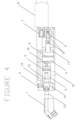
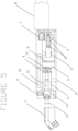
- the linear motion converter comprises a slider crank mechanism 12, which slider crank is operatively coupled to the motor 8 and reducing gears 7 and 9.
- the tool further comprises an air chamber 5, 17 that accepts a compression piston 6 with a first end and a second end, which compression piston 6 is actuated by the linear motion converter 12.
- the compression piston will have a smaller longitudinal dimension than the air chamber that contains the piston, it will be apparent that an air mass will be present at either end of the compression piston while the compression piston is within the air chamber.
- the air mass disposed between the head of compression piston and the striker will be referred to as the "forward air chamber portion” or “forward air chamber,” 5 and the air mass disposed between the end of the compression piston that is proximate to the linear motion converter and the motor of the tool will be referred to as the "rear air chamber portion” or “rear air chamber” 17.
- the motor of the tool causes the linear motion converter to move the compression piston until sufficient pressure is built within the forward air chamber 5 that is disposed between the forward end of the compression piston and the rearward end of the striker 4 to either overcome a detent 10 that otherwise retains the striker in a rearward position and/or the inertia and frictional force that holds the striker 4 in a position. Once this sufficient pressure is reached, the force of the air pressure accelerates the striker 4, which striker slides axially down a cavity internal to the tool housing and strikes the forward anvil impact plate 15.
- the resultant force is communicated through the anvil 14 that is proximate to the impact plate 15 and, optionally, through the broach adapter 1 (which adapter will be described in more detail below) to which a broach, chisel, or other device for seating or removing an implant, or prosthesis may be attached.
- the broach adapter 1 which adapter will be described in more detail below
- a broach adapter 1 In the event that a broach adapter 1 is attached to the anvil 14, the force is communicated through the broach adapter 1 to which the broach, chisel, or other device for seating or removing an implant, or prosthesis is attached.
- a forward and rear directed impacting force can be applied on the broach, chisel, or other device, or implant/prosthesis.
- the compression piston preferably has a cavity on the head thereof, which cavity creates pressure during the return stroke of the piston, which pressure causes the front end of the striker to move away from the forward anvil impact plate impact the rearward point of impact of the anvil element. It will be apparent that the striker impacting the rear anvil impact plate will communicate a negative force to the front of the anvil (and broach, chisel, or other device), which negative force will move the broach, chisel, or other device away from the location of impact in a surgical area.
- the slider crank embodiment of the tool facilitates controlled continuous impacting of the striker and anvil.
- the slider crank After causing compression by the compression piston, the slider crank returns to the bottom of its stroke, which return releases pressure on the striker and, in the above-described embodiment wherein the piston comprises a cavity on the head thereof, may pressurize the front of the striker, causing the striker to return to its initial rest position.
- the linear motion converter (such as the slider crank described herein) will stop at or near the rear position, thus releasing the forward pressure on the striker and allowing the striker to return it to its starting position in readiness for another stroke.
- a user may cause the tool to impact selectively (as opposed to repeatedly), thus allowing further control of the impacts and the creation or shaping of the surgical area, for example.
- a positional sensor coupled operatively to the control unit may be provided to assist in regulating a preferred positional cyclic operation of the linear motion converter.
- the control unit may cause the slider crank to come to rest at or near the fully back position in readiness to generate pressure for the next impact upon receiving a signal from the positional sensor that the slider crank has reached the bottom dead center position.
- the control unit may be directly coupled to the linear motion converter for initiating and ceasing operation of the linear motion converter.
- the control unit is further capable of operating the force control means for selectively tuning the amount of impact force per cycle.
- the force control means for selectively tuning the amount of impact force per cycle.
- the tool can avoid damage caused by uncontrolled impacts or impacts of excessive force.
- a user may reduce the impact setting in the case of an elderly patent with osteoporosis, or may increase the impact setting for more resilient or intact athletic bone structures.
- One such force control preferably comprises a selectable release setting on a mechanical detent that holds the striker. It will be apparent that the striker will impact the anvil with greater force in the case where the pressure needed to dislodge the striker from the detent is increased.
- the detent may comprise a solenoid, which solenoid may activate upon a predetermined buildup of pressure, after which the striker 4 is released, allowing it to impact the anvil.
- the control unit may also control the force of impacting by modulating the speed of advancing (forward directional travel) and/or the speed of retraction (rearward directional travel) of the compression piston. It will be apparent that the modulation of speed of the compression piston will affect the buildup of pressure for forward and rearward directional travel of the striker. For example, where the speed of the forward direction of the piston is relatively high, and the speed of the rearward direction of the piston is relatively low, the velocity of the striker in the forward direction will be much higher, causing the imparted percussive impact of the striker to be greater in the forward direction of the piston and striker.
- This modulation of the speed of the piston in the forward and rearward direction allows a user to create a greater impacting force, when so desired (e.g., to create a surgical area) or a greater rearward force, to facilitate removing a broach, chisel, or other device from the surgical area, for example.
- the tool allows for bidirectional movement of the broach, chisel, or other device during operation, which creates a very efficient technique for machining the cavity.
- the motor of the tool may be configured to assist particularly with such multidirectional impacting.
- the motor may operate under pulse-width modulation for rearward striking and may operate under full or continuous speed for forward striking of the striker.
- the broach, chisel, or other device attached to the tool may undergo near forward only motion, which operation will facilitate the creation of an implant seat.
- the motor may operate under pulse-width modulation for forward striking and may operate under full or continuous speed for rearward impacting, which operation can create an extraction motion useful for dislodging a broach, chisel, or other device that has become stuck or removing an implant.
- the tool comprises a positional sensor, such as an anvil positional sensor that may be operatively coupled to the control unit of the striker of the tool.
- This positional sensor is capable of determining whether the operator is pushing or pulling on the tool. For instance, the sensor may determine such pushing or pulling based upon the position of the broach-holding adapter or anvil. This determination can have the effect that when a user is exerting force on the tool in a particular direction the impacting of the striker is accordingly adjusted. For example, if the sensor determines that the user is pushing on the tool or is pushing the tool against an object, that sensor can cause the striker to impact in a forward direction. If the sensor determines that the user is pulling on the tool, that sensor may cause the striker to impact in a rearward direction or may cause a pulling force to be exerted on the striker by way of the cycling of the slider crank.
- the tool may further comprise a lighting element, and, in an embodiment, the lighting element may comprise an LED arrangement, which lighting element may be capable of illuminating a user's work area.
- the LED may be disposed on the housing of the tool and may be oriented toward a patient's body or surgical cavity.
- the tool may further comprise a plate or other flat surface at the end of the tool that is distal to the surgical area, which plate may allow a user to apply selective manual pressure on a broach, chisel or other device, or a surgical implant as dictated by surgical or physical conditions. For instance, if a broach is firmly lodged within a cavity such that the operation of the tool would not remove the broach, the user may manually tap on the plate to dislodge the broach.
- the tool may further comprise a torsion sensor, which torsion sensor may be capable of determining a lateral or deviating force or movement of the tool, such that if the tool is sensed to deviate from a pre-determined magnitude at the broach/implant interface, a signal may emit to notify the user of such deviation. In this manner and otherwise, the tool facilitates consistent axial broaching and implant seating.
- the broach adapter may comprise a parallel 4-bar arrangement.
- the adapter may receive a broach for anterior or posterior joint replacement.
- the parallel 4-bar mechanism of the adapter may facilitate receiving and orienting the broach in a variety of positions, such as in a centered position, or in an offset left or right position.
- the adapter will maintain the broach in an orientation that is parallel or co-linear to the body of the tool and the striker.
- the broach adapter may also comprise clamps, a vice, or any other fastener that may securely hold the broach, chisel, or other device, during operation of the tool.
- the tool may further comprise handgrips disposed on the housing of the tool, which handgrips may include a rubberized or other tacky coating removably disposed thereon. Such coating facilitates comfortable operation of the tool and improves the user's hold on the tool for increased control thereof and reduced fatigue during operation of the tool.
- a user such as a surgeon firmly holds the tool by the handle grip or grips and utilizes light emitted by the LED to illuminate a work area and accurately position a broach, chisel or other device that has been attached to the tool on a desired location on the prosthesis or implant.
- the reciprocating movement imparted by the tool upon the broach, chisel or other device causes tapping of the implant and thereby enables proper seating or removal of the prosthesis or the implant into or out of an implant cavity.
- the warning system may alert the user in the event that a bending moment above a certain magnitude is detected at a broach (or chisel or other device)/implant interface.
- the tool disclosed herein provides various advantages over the prior art. It facilitates controlled impacting at a surgical site, which minimizes unnecessary damage to a patient's body and which allows precise shaping of a implant or prosthesis seat.
- the tool also allows the user to modulate the direction and force of impacts, which improves the user's ability to manipulate the tool.
- the force control adjustment of the impact settings allows a user to set the force of impact according to a particular bone type or other profile of a patient. The tool thereby enables proper seating or removal of the prosthesis or the implant into or out of an implant cavity.
Landscapes
- Health & Medical Sciences (AREA)
- Life Sciences & Earth Sciences (AREA)
- Surgery (AREA)
- Orthopedic Medicine & Surgery (AREA)
- Medical Informatics (AREA)
- Engineering & Computer Science (AREA)
- Biomedical Technology (AREA)
- Heart & Thoracic Surgery (AREA)
- Nuclear Medicine, Radiotherapy & Molecular Imaging (AREA)
- Molecular Biology (AREA)
- Animal Behavior & Ethology (AREA)
- General Health & Medical Sciences (AREA)
- Public Health (AREA)
- Veterinary Medicine (AREA)
- Dentistry (AREA)
- Oral & Maxillofacial Surgery (AREA)
- Surgical Instruments (AREA)
Claims (14)
- Orthopädisches Schlagwerkzeug für das Schlagen auf ein Objekt, wobei das Werkzeug umfasst:eine Motoranordnung (8, 12), die einen Motor (8) und einen Linearbewegungswandler (12) umfasst;einen Kolben (6), der mit der Motoranordnung (8, 12) wirkgekoppelt ist, wobei der Kolben (6) ein vorderes Ende und ein hinteres Ende aufweist;eine Luftkammer;ein Schlagelement (4);eine Steuereinheit;einen Räumnadeladapter (1), der eine Räumnadel, einen Meißel, eine Reibahle oder ein anderes chirurgisches Instrument halten kann; undein Ambosselement (14), das zum Aufnehmen eines Abschnitts des Räumnadeladapters (1) angepasst ist, wobei der Räumnadeladapter (1) mit dem Ambosselement (14) wirkgekoppelt ist;eine vordere Schlagplatte (15); undeine hintere Schlagplatte (16);wobei die Luftkammer eine vordere Luftkammer (5) in der Nähe des vorderen Endes des Kolbens (6) und eine hintere Luftkammer (17) in der Nähe des hinteren Endes des Kolbens (6) umfasst;wobei die Steuereinheit konfiguriert ist, um die Motoranordnung (8, 12) anzuweisen, den Linearbewegungswandler (12) dazu zu veranlassen, den Kolben in Zyklen von vorwärts- und rückwärtsgerichteter Hin- und Herbewegung zu bewegen;wobei die Vorwärtsbewegung des Kolbens (6) während des Zyklus eine Kompression der Luft in der vorderen Luftkammer (5) bewirkt;und wobei die Rückwärtsbewegung des Kolbens (6) während des Zyklus eine Kompression der Luft in der hinteren Luftkammer (17) bewirkt;wobei bewirkt wird, dass sich das Schlagelement (4) bewegt, um auf die vordere Schlagplatte (15) bei Anwendung von Druckluft aus der vorderen Luftkammer (5) zu schlagen;und wobei bewirkt wird, dass sich das Schlagelement (4) bewegt, um auf die hintere Schlagplatte (16) bei Anwendung von Druckluft aus der hinteren Luftkammer (17) zu schlagen;wobei die Steuereinheit konfiguriert ist, um ein perkussives Schlagen des Schlagelements (4) sowohl auf die vordere Schlagplatte (15) als auch auf die hintere Schlagplatte (16) in einem Zyklus der Hin- und Herbewegung des Kolbens zu ermöglichen.
- Orthopädisches Schlagwerkzeug nach Anspruch 1, wobei:das orthopädische Schlagwerkzeug ferner einen an die Luftkammer angrenzenden Luftdurchlass (19) umfasst, wobei der Luftdurchlass (19) in der Lage ist, Luft von der Luftkammer an das Schlagelement (4) weiterzuleiten;wobei die Kompression der Luft innerhalb der hinteren Luftkammer (17) durch den Durchlass (19) und auf das Schlagelement (4) weitergeleitet wird, so dass die durch den Luftdurchlass (19) weitergeleitete Druckluft bewirkt, dass das Schlagelement (4) auf die hintere Schlagplatte (16) schlägt;wobei Schläge auf die vordere und hintere Schlagplatte (15, 16) eine Kraft auf den Räumnadeladapter (1) in einer ersten und einer zweiten Richtung ausüben, wobei die zweite Richtung im Wesentlichen kollinear und entgegengesetzt zur ersten Richtung ist.
- Orthopädisches Schlagwerkzeug nach einem der vorstehenden Ansprüche, wobei die Motoranordnung (8, 12) einen Schubkurbelmechanismus umfasst.
- Orthopädisches Schlagwerkzeug nach einem der vorstehenden Ansprüche, wobei die Motoranordnung (8, 12) einen Schwingspulenmotor umfasst.
- Orthopädisches Schlagwerkzeug nach einem der vorstehenden Ansprüche, wobei:
das orthopädische Schlagwerkzeug einen Positionssensor umfasst, der entweder mit der Steuereinheit des orthopädischen Schlagwerkzeugs oder der Motoranordnung (8, 12) des orthopädischen Schlagwerkzeugs wirkgekoppelt ist, wobei der Sensor konfiguriert ist, um zu bestimmen, ob das Werkzeug zu einem Objekt hin gedrückt oder von einem Objekt weg gezogen wird, wobei der Sensor konfiguriert ist, um zu bewirken, dass die Steuereinheit oder Motoranordnung (8, 12) des orthopädischen Schlagwerkzeugs das Schlagelement (4) anweist, eine größere Kraft auf die vordere Schlagplatte (15) und eine geringere Kraft auf die hintere Schlagplatte (16) auszuüben, wenn erfasst wird, dass das Werkzeug in Richtung eines Objekts gedrückt wird, und der Sensor konfiguriert ist, um zu bewirken, dass die Steuereinheit oder Motoranordnung (8, 12) des orthopädischen Schlagwerkzeugs das Schlagelement (4) anweist, eine größere Kraft auf die vordere Schlagplatte (15) und eine geringere Kraft auf die hintere Schlagplatte (16) auszuüben, wenn erfasst wird, dass das Werkzeug von einem Objekt weg gedrückt wird. - Orthopädisches Schlagwerkzeug nach einem der vorstehenden Ansprüche, wobei das Werkzeug einen Torsionssensor umfasst, der konfiguriert ist zum:Bestimmen einer seitlichen Bewegung des orthopädischen Schlagwerkzeugs; undSignalisieren dieser seitlichen Bewegung.
- Orthopädisches Schlagwerkzeug nach einem der vorstehenden Ansprüche, wobei das orthopädische Schlagwerkzeug ferner ein Beleuchtungselement umfasst, das auf einer Außenoberfläche des orthopädischen Schlagwerkzeugs angeordnet ist, wobei das Beleuchtungselement mit der Steuereinheit wirkgekoppelt ist.
- Orthopädisches Schlagwerkzeug nach einem der vorstehenden Ansprüche, wobei die Geschwindigkeit des Schlagelements (4) durch die Geschwindigkeit gesteuert werden kann, mit der die Luft komprimiert oder dekomprimiert wird.
- Orthopädisches Schlagwerkzeug nach einem der vorstehenden Ansprüche, wobei der Räumnadeladapter (1) eine Einstellung aufweist, die konfiguriert ist, um eine angebrachte Räumnadel, einen Meißel, eine Reibahle oder ein anderes chirurgisches Instrument von der Mittelachse des orthopädischen Schlagwerkzeugs zu versetzen, während eine parallele Ausrichtung der Räumnadel, des Meißels, der Reibahle oder des anderen chirurgischen Instruments in Bezug auf die Mittelachse des orthopädischen Schlagwerkzeugs beibehalten wird.
- Orthopädisches Schlagwerkzeug nach Anspruch 1, ferner umfassend eine Feststellvorrichtung (10) zum Zurückhalten des Schlagelements (4) in einer Position.
- Orthopädisches Schlagwerkzeug nach Anspruch 10, wobei:
die Steuereinheit konfiguriert ist, um die Motoranordnung (8, 12) anzuweisen, eine Bewegung des Kolbens (6) und eine Kompression der Luft innerhalb der Luftkammer zu bewirken, so dass, wenn der Druck der Druckluft eine Kraft der Feststellvorrichtung (10) übersteigt, das Schlagelement (4) dazu veranlasst wird, sich von einer ersten Position zu einer zweiten Position zu bewegen, wodurch es auf die vordere (15) oder hintere (16) Schlagplatte schlägt. - Orthopädisches Schlagwerkzeug nach Anspruch 10 oder 11, wobei eine Rückhaltekraft der Feststellvorrichtung (10) von einer Magnetspule gesteuert werden kann, die mit der Steuereinheit wirkgekoppelt ist.
- Orthopädisches Schlagwerkzeug nach einem der Ansprüche 10 bis 12, ferner umfassend eine Kraftanpassungssteuerung, die mit der Steuereinheit wirkgekoppelt ist, wobei die Kraftanpassungssteuerung zum mindestens einem von Ändern der Geschwindigkeit, mit der sich der Kolben (6) innerhalb der Luftkammer bewegt, und Ändern der Rückhaltealtekraft der Feststellvorrichtung (10) betreibbar ist.
- Orthopädisches Schlagwerkzeug nach einem der vorstehenden Ansprüche, wobei sich der Räumnadeladapter (1) in der Nähe der vorderen Schlagplatte (15) des Ambosselements (14) und distal der hinteren Schlagplatte (16) des Ambosselements (14) befindet.
Applications Claiming Priority (4)
| Application Number | Priority Date | Filing Date | Title |
|---|---|---|---|
| US201013980329A | 2010-12-29 | 2010-12-29 | |
| US12/980,329 US8695726B2 (en) | 2010-12-29 | 2010-12-29 | Electric motor driven tool for orthopedic impacting |
| PCT/US2011/067626 WO2012092387A2 (en) | 2010-12-29 | 2011-12-28 | Electric motor driven tool for orthopedic impacting |
| EP11854028.5A EP2658462B1 (de) | 2010-12-29 | 2011-12-28 | Durch einen elektromotor angetriebenes werkzeug für orthopädische eingriffe |
Related Parent Applications (1)
| Application Number | Title | Priority Date | Filing Date |
|---|---|---|---|
| EP11854028.5A Division EP2658462B1 (de) | 2010-12-29 | 2011-12-28 | Durch einen elektromotor angetriebenes werkzeug für orthopädische eingriffe |
Publications (3)
| Publication Number | Publication Date |
|---|---|
| EP3284429A1 EP3284429A1 (de) | 2018-02-21 |
| EP3284429B1 true EP3284429B1 (de) | 2024-11-06 |
| EP3284429C0 EP3284429C0 (de) | 2024-11-06 |
Family
ID=93014698
Family Applications (1)
| Application Number | Title | Priority Date | Filing Date |
|---|---|---|---|
| EP17179081.9A Active EP3284429B1 (de) | 2010-12-29 | 2011-12-28 | Durch einen elektromotor angetriebenes werkzeug für orthopädische eingriffe |
Country Status (1)
| Country | Link |
|---|---|
| EP (1) | EP3284429B1 (de) |
Families Citing this family (1)
| Publication number | Priority date | Publication date | Assignee | Title |
|---|---|---|---|---|
| GB2599706B (en) | 2020-10-09 | 2022-12-07 | Additive Instruments Ltd | Impactor |
Family Cites Families (10)
| Publication number | Priority date | Publication date | Assignee | Title |
|---|---|---|---|---|
| US974267A (en) * | 1908-10-12 | 1910-11-01 | John J Hennessy | Drilling apparatus. |
| US4298074A (en) * | 1976-08-09 | 1981-11-03 | American Safety Equipment Corporation | Surgical device using impulse motor |
| US5057112A (en) | 1990-01-04 | 1991-10-15 | Intermedics Orthopedics, Inc. | Pneumatically powered orthopedic broach |
| US5352230A (en) * | 1992-02-19 | 1994-10-04 | Biomet, Inc. | Pneumatic impulse tool |
| ES2122055T3 (es) * | 1993-03-30 | 1998-12-16 | Integral Medizintechnik | Herramienta de percusion neumatica. |
| DE19624446C1 (de) * | 1996-06-19 | 1998-03-26 | Ferton Holding | Chirurgisches Instrument zum mechanischen Entfernen von Knochenzement, sowie Verfahren zum Erzeugen von Stoßwellen |
| US9451968B2 (en) * | 2002-05-31 | 2016-09-27 | Vidacare LLC | Powered drivers, intraosseous devices and methods to access bone marrow |
| US20050116673A1 (en) * | 2003-04-18 | 2005-06-02 | Rensselaer Polytechnic Institute | Methods and systems for controlling the operation of a tool |
| DE102007000488A1 (de) * | 2007-09-12 | 2009-03-19 | Hilti Aktiengesellschaft | Handwerkzeugmaschine mit Luftfederschlagswerk, Linearmotor und Steuerverfahren |
| WO2010045158A2 (en) * | 2008-10-13 | 2010-04-22 | Piezo Resonance Innovations, Inc. | Tool for incising tissue |
-
2011
- 2011-12-28 EP EP17179081.9A patent/EP3284429B1/de active Active
Also Published As
| Publication number | Publication date |
|---|---|
| EP3284429A1 (de) | 2018-02-21 |
| EP3284429C0 (de) | 2024-11-06 |
Similar Documents
| Publication | Publication Date | Title |
|---|---|---|
| US12023045B2 (en) | Electric motor driven tool for orthopedic impacting | |
| AU2017210500B2 (en) | Electric motor driven tool for orthopedic impacting | |
| JP6703055B2 (ja) | 整形外科用衝撃付与電気モータ駆動器具 | |
| EP3284429B1 (de) | Durch einen elektromotor angetriebenes werkzeug für orthopädische eingriffe | |
| HK1252077A1 (en) | Electric motor driven tool for orthopedic impacting | |
| JP6429845B2 (ja) | 整形外科用衝撃付与電気モータ駆動器具 | |
| HK1208336B (en) | Electric motor driven tool for orthopedic impacting |
Legal Events
| Date | Code | Title | Description |
|---|---|---|---|
| PUAI | Public reference made under article 153(3) epc to a published international application that has entered the european phase |
Free format text: ORIGINAL CODE: 0009012 |
|
| STAA | Information on the status of an ep patent application or granted ep patent |
Free format text: STATUS: THE APPLICATION HAS BEEN PUBLISHED |
|
| AC | Divisional application: reference to earlier application |
Ref document number: 2658462 Country of ref document: EP Kind code of ref document: P |
|
| AK | Designated contracting states |
Kind code of ref document: A1 Designated state(s): AL AT BE BG CH CY CZ DE DK EE ES FI FR GB GR HR HU IE IS IT LI LT LU LV MC MK MT NL NO PL PT RO RS SE SI SK SM TR |
|
| RAP1 | Party data changed (applicant data changed or rights of an application transferred) |
Owner name: MEDICAL ENTERPRISES DISTRIBUTION, LLC |
|
| STAA | Information on the status of an ep patent application or granted ep patent |
Free format text: STATUS: REQUEST FOR EXAMINATION WAS MADE |
|
| 17P | Request for examination filed |
Effective date: 20180820 |
|
| RBV | Designated contracting states (corrected) |
Designated state(s): AL AT BE BG CH CY CZ DE DK EE ES FI FR GB GR HR HU IE IS IT LI LT LU LV MC MK MT NL NO PL PT RO RS SE SI SK SM TR |
|
| RAP1 | Party data changed (applicant data changed or rights of an application transferred) |
Owner name: DEPUY SYNTHES PRODUCTS, INC. |
|
| REG | Reference to a national code |
Ref country code: HK Ref legal event code: DE Ref document number: 1252077 Country of ref document: HK |
|
| STAA | Information on the status of an ep patent application or granted ep patent |
Free format text: STATUS: EXAMINATION IS IN PROGRESS |
|
| 17Q | First examination report despatched |
Effective date: 20230628 |
|
| GRAP | Despatch of communication of intention to grant a patent |
Free format text: ORIGINAL CODE: EPIDOSNIGR1 |
|
| STAA | Information on the status of an ep patent application or granted ep patent |
Free format text: STATUS: GRANT OF PATENT IS INTENDED |
|
| INTG | Intention to grant announced |
Effective date: 20240613 |
|
| GRAS | Grant fee paid |
Free format text: ORIGINAL CODE: EPIDOSNIGR3 |
|
| GRAA | (expected) grant |
Free format text: ORIGINAL CODE: 0009210 |
|
| STAA | Information on the status of an ep patent application or granted ep patent |
Free format text: STATUS: THE PATENT HAS BEEN GRANTED |
|
| AC | Divisional application: reference to earlier application |
Ref document number: 2658462 Country of ref document: EP Kind code of ref document: P |
|
| AK | Designated contracting states |
Kind code of ref document: B1 Designated state(s): AL AT BE BG CH CY CZ DE DK EE ES FI FR GB GR HR HU IE IS IT LI LT LU LV MC MK MT NL NO PL PT RO RS SE SI SK SM TR |
|
| REG | Reference to a national code |
Ref country code: GB Ref legal event code: FG4D |
|
| REG | Reference to a national code |
Ref country code: CH Ref legal event code: EP |
|
| REG | Reference to a national code |
Ref country code: DE Ref legal event code: R096 Ref document number: 602011075086 Country of ref document: DE |
|
| REG | Reference to a national code |
Ref country code: IE Ref legal event code: FG4D |
|
| U01 | Request for unitary effect filed |
Effective date: 20241121 |
|
| U07 | Unitary effect registered |
Designated state(s): AT BE BG DE DK EE FI FR IT LT LU LV MT NL PT RO SE SI Effective date: 20241128 |
|
| U20 | Renewal fee for the european patent with unitary effect paid |
Year of fee payment: 14 Effective date: 20241203 |
|
| PG25 | Lapsed in a contracting state [announced via postgrant information from national office to epo] |
Ref country code: HR Free format text: LAPSE BECAUSE OF FAILURE TO SUBMIT A TRANSLATION OF THE DESCRIPTION OR TO PAY THE FEE WITHIN THE PRESCRIBED TIME-LIMIT Effective date: 20241106 Ref country code: IS Free format text: LAPSE BECAUSE OF FAILURE TO SUBMIT A TRANSLATION OF THE DESCRIPTION OR TO PAY THE FEE WITHIN THE PRESCRIBED TIME-LIMIT Effective date: 20250306 |
|
| PG25 | Lapsed in a contracting state [announced via postgrant information from national office to epo] |
Ref country code: ES Free format text: LAPSE BECAUSE OF FAILURE TO SUBMIT A TRANSLATION OF THE DESCRIPTION OR TO PAY THE FEE WITHIN THE PRESCRIBED TIME-LIMIT Effective date: 20241106 |
|
| PG25 | Lapsed in a contracting state [announced via postgrant information from national office to epo] |
Ref country code: NO Free format text: LAPSE BECAUSE OF FAILURE TO SUBMIT A TRANSLATION OF THE DESCRIPTION OR TO PAY THE FEE WITHIN THE PRESCRIBED TIME-LIMIT Effective date: 20250206 |
|
| PG25 | Lapsed in a contracting state [announced via postgrant information from national office to epo] |
Ref country code: GR Free format text: LAPSE BECAUSE OF FAILURE TO SUBMIT A TRANSLATION OF THE DESCRIPTION OR TO PAY THE FEE WITHIN THE PRESCRIBED TIME-LIMIT Effective date: 20250207 |
|
| PGFP | Annual fee paid to national office [announced via postgrant information from national office to epo] |
Ref country code: CH Payment date: 20250101 Year of fee payment: 14 |
|
| PG25 | Lapsed in a contracting state [announced via postgrant information from national office to epo] |
Ref country code: PL Free format text: LAPSE BECAUSE OF FAILURE TO SUBMIT A TRANSLATION OF THE DESCRIPTION OR TO PAY THE FEE WITHIN THE PRESCRIBED TIME-LIMIT Effective date: 20241106 |
|
| PG25 | Lapsed in a contracting state [announced via postgrant information from national office to epo] |
Ref country code: RS Free format text: LAPSE BECAUSE OF FAILURE TO SUBMIT A TRANSLATION OF THE DESCRIPTION OR TO PAY THE FEE WITHIN THE PRESCRIBED TIME-LIMIT Effective date: 20250206 |
|
| PG25 | Lapsed in a contracting state [announced via postgrant information from national office to epo] |
Ref country code: SM Free format text: LAPSE BECAUSE OF FAILURE TO SUBMIT A TRANSLATION OF THE DESCRIPTION OR TO PAY THE FEE WITHIN THE PRESCRIBED TIME-LIMIT Effective date: 20241106 |
|
| PG25 | Lapsed in a contracting state [announced via postgrant information from national office to epo] |
Ref country code: SK Free format text: LAPSE BECAUSE OF FAILURE TO SUBMIT A TRANSLATION OF THE DESCRIPTION OR TO PAY THE FEE WITHIN THE PRESCRIBED TIME-LIMIT Effective date: 20241106 |
|
| REG | Reference to a national code |
Ref country code: HK Ref legal event code: WD Ref document number: 1252077 Country of ref document: HK |
|
| PG25 | Lapsed in a contracting state [announced via postgrant information from national office to epo] |
Ref country code: CZ Free format text: LAPSE BECAUSE OF FAILURE TO SUBMIT A TRANSLATION OF THE DESCRIPTION OR TO PAY THE FEE WITHIN THE PRESCRIBED TIME-LIMIT Effective date: 20241106 |
|
| PLBE | No opposition filed within time limit |
Free format text: ORIGINAL CODE: 0009261 |
|
| STAA | Information on the status of an ep patent application or granted ep patent |
Free format text: STATUS: NO OPPOSITION FILED WITHIN TIME LIMIT |
|
| PG25 | Lapsed in a contracting state [announced via postgrant information from national office to epo] |
Ref country code: MC Free format text: LAPSE BECAUSE OF FAILURE TO SUBMIT A TRANSLATION OF THE DESCRIPTION OR TO PAY THE FEE WITHIN THE PRESCRIBED TIME-LIMIT Effective date: 20241106 |
|
| 26N | No opposition filed |
Effective date: 20250807 |
|
| PG25 | Lapsed in a contracting state [announced via postgrant information from national office to epo] |
Ref country code: IE Free format text: LAPSE BECAUSE OF NON-PAYMENT OF DUE FEES Effective date: 20241228 |
|
| U20 | Renewal fee for the european patent with unitary effect paid |
Year of fee payment: 15 Effective date: 20251110 |
|
| REG | Reference to a national code |
Ref country code: CH Ref legal event code: U11 Free format text: ST27 STATUS EVENT CODE: U-0-0-U10-U11 (AS PROVIDED BY THE NATIONAL OFFICE) Effective date: 20260101 |
|
| PGFP | Annual fee paid to national office [announced via postgrant information from national office to epo] |
Ref country code: GB Payment date: 20251114 Year of fee payment: 15 |