EP3284098B2 - Device for interrupting non-short circuit currents only, in particular disconnector or earthing switch - Google Patents
Device for interrupting non-short circuit currents only, in particular disconnector or earthing switch Download PDFInfo
- Publication number
- EP3284098B2 EP3284098B2 EP15715284.4A EP15715284A EP3284098B2 EP 3284098 B2 EP3284098 B2 EP 3284098B2 EP 15715284 A EP15715284 A EP 15715284A EP 3284098 B2 EP3284098 B2 EP 3284098B2
- Authority
- EP
- European Patent Office
- Prior art keywords
- arc
- designed
- arcing
- region
- piston
- Prior art date
- Legal status (The legal status is an assumption and is not a legal conclusion. Google has not performed a legal analysis and makes no representation as to the accuracy of the status listed.)
- Active
Links
- 238000010791 quenching Methods 0.000 claims description 51
- 241000722921 Tulipa gesneriana Species 0.000 claims description 34
- 230000006835 compression Effects 0.000 claims description 23
- 238000007906 compression Methods 0.000 claims description 23
- 230000008033 biological extinction Effects 0.000 claims description 19
- 125000004432 carbon atom Chemical group C* 0.000 claims description 19
- CURLTUGMZLYLDI-UHFFFAOYSA-N Carbon dioxide Chemical compound O=C=O CURLTUGMZLYLDI-UHFFFAOYSA-N 0.000 claims description 18
- KRHYYFGTRYWZRS-UHFFFAOYSA-N Fluorane Chemical compound F KRHYYFGTRYWZRS-UHFFFAOYSA-N 0.000 claims description 16
- IYRWEQXVUNLMAY-UHFFFAOYSA-N fluoroketone group Chemical group FC(=O)F IYRWEQXVUNLMAY-UHFFFAOYSA-N 0.000 claims description 16
- 239000000463 material Substances 0.000 claims description 14
- 239000000203 mixture Substances 0.000 claims description 13
- 239000001569 carbon dioxide Substances 0.000 claims description 11
- 229910002092 carbon dioxide Inorganic materials 0.000 claims description 11
- 229910052760 oxygen Inorganic materials 0.000 claims description 10
- QVGXLLKOCUKJST-UHFFFAOYSA-N atomic oxygen Chemical compound [O] QVGXLLKOCUKJST-UHFFFAOYSA-N 0.000 claims description 9
- 239000001301 oxygen Substances 0.000 claims description 9
- 230000008093 supporting effect Effects 0.000 claims description 5
- 238000002679 ablation Methods 0.000 claims description 4
- IJGRMHOSHXDMSA-UHFFFAOYSA-N Atomic nitrogen Chemical compound N#N IJGRMHOSHXDMSA-UHFFFAOYSA-N 0.000 claims description 2
- 229920001774 Perfluoroether Polymers 0.000 claims description 2
- 230000007704 transition Effects 0.000 claims 1
- 238000009413 insulation Methods 0.000 description 17
- 238000001816 cooling Methods 0.000 description 14
- SFZCNBIFKDRMGX-UHFFFAOYSA-N sulfur hexafluoride Chemical compound FS(F)(F)(F)(F)F SFZCNBIFKDRMGX-UHFFFAOYSA-N 0.000 description 11
- 239000007789 gas Substances 0.000 description 10
- 238000007664 blowing Methods 0.000 description 7
- 230000001965 increasing effect Effects 0.000 description 6
- ABQIAHFCJGVSDJ-UHFFFAOYSA-N 1,1,1,3,4,4,4-heptafluoro-3-(trifluoromethyl)butan-2-one Chemical compound FC(F)(F)C(=O)C(F)(C(F)(F)F)C(F)(F)F ABQIAHFCJGVSDJ-UHFFFAOYSA-N 0.000 description 5
- 239000012159 carrier gas Substances 0.000 description 4
- 230000000694 effects Effects 0.000 description 4
- 229920001343 polytetrafluoroethylene Polymers 0.000 description 4
- 239000004810 polytetrafluoroethylene Substances 0.000 description 4
- CDOOAUSHHFGWSA-OWOJBTEDSA-N (e)-1,3,3,3-tetrafluoroprop-1-ene Chemical compound F\C=C\C(F)(F)F CDOOAUSHHFGWSA-OWOJBTEDSA-N 0.000 description 3
- FXRLMCRCYDHQFW-UHFFFAOYSA-N 2,3,3,3-tetrafluoropropene Chemical compound FC(=C)C(F)(F)F FXRLMCRCYDHQFW-UHFFFAOYSA-N 0.000 description 3
- 230000015572 biosynthetic process Effects 0.000 description 3
- 230000002349 favourable effect Effects 0.000 description 3
- 231100000053 low toxicity Toxicity 0.000 description 3
- AASDJASZOZGYMM-UHFFFAOYSA-N 2,3,3,3-tetrafluoro-2-(trifluoromethyl)propanenitrile Chemical compound FC(F)(F)C(F)(C#N)C(F)(F)F AASDJASZOZGYMM-UHFFFAOYSA-N 0.000 description 2
- CBENFWSGALASAD-UHFFFAOYSA-N Ozone Chemical compound [O-][O+]=O CBENFWSGALASAD-UHFFFAOYSA-N 0.000 description 2
- 230000015556 catabolic process Effects 0.000 description 2
- 230000007613 environmental effect Effects 0.000 description 2
- 125000001153 fluoro group Chemical group F* 0.000 description 2
- 230000001939 inductive effect Effects 0.000 description 2
- 238000000034 method Methods 0.000 description 2
- 231100000252 nontoxic Toxicity 0.000 description 2
- 230000003000 nontoxic effect Effects 0.000 description 2
- -1 organofluorine compounds Chemical class 0.000 description 2
- FDPIMTJIUBPUKL-UHFFFAOYSA-N pentan-3-one Chemical compound CCC(=O)CC FDPIMTJIUBPUKL-UHFFFAOYSA-N 0.000 description 2
- 229960000909 sulfur hexafluoride Drugs 0.000 description 2
- DMUPYMORYHFFCT-OWOJBTEDSA-N (e)-1,2,3,3,3-pentafluoroprop-1-ene Chemical compound F\C=C(\F)C(F)(F)F DMUPYMORYHFFCT-OWOJBTEDSA-N 0.000 description 1
- ZUAQTIHDWIHCSV-OWOJBTEDSA-N (e)-1,2,3,3-tetrafluoroprop-1-ene Chemical compound F\C=C(\F)C(F)F ZUAQTIHDWIHCSV-OWOJBTEDSA-N 0.000 description 1
- DMUPYMORYHFFCT-UPHRSURJSA-N (z)-1,2,3,3,3-pentafluoroprop-1-ene Chemical compound F\C=C(/F)C(F)(F)F DMUPYMORYHFFCT-UPHRSURJSA-N 0.000 description 1
- ZUAQTIHDWIHCSV-UPHRSURJSA-N (z)-1,2,3,3-tetrafluoroprop-1-ene Chemical compound F\C=C(/F)C(F)F ZUAQTIHDWIHCSV-UPHRSURJSA-N 0.000 description 1
- CDOOAUSHHFGWSA-UPHRSURJSA-N (z)-1,3,3,3-tetrafluoroprop-1-ene Chemical compound F\C=C/C(F)(F)F CDOOAUSHHFGWSA-UPHRSURJSA-N 0.000 description 1
- ALVFUQVKODCQQB-UHFFFAOYSA-N 1,1,1,2,2,4,4,5,5,5-decafluoropentan-3-one Chemical compound FC(F)(F)C(F)(F)C(=O)C(F)(F)C(F)(F)F ALVFUQVKODCQQB-UHFFFAOYSA-N 0.000 description 1
- GCDWNCOAODIANN-UHFFFAOYSA-N 1,1,1,2,2-pentafluoro-2-methoxyethane Chemical compound COC(F)(F)C(F)(F)F GCDWNCOAODIANN-UHFFFAOYSA-N 0.000 description 1
- GWFGVRFAJMXXBL-UHFFFAOYSA-N 1,1,1,3,3,4,4,5,5,5-decafluoropentan-2-one Chemical compound FC(F)(F)C(=O)C(F)(F)C(F)(F)C(F)(F)F GWFGVRFAJMXXBL-UHFFFAOYSA-N 0.000 description 1
- MWVZDOGOCGRMOE-UHFFFAOYSA-N 1,1,1-trifluoro-2-(trifluoromethoxy)ethane Chemical compound FC(F)(F)COC(F)(F)F MWVZDOGOCGRMOE-UHFFFAOYSA-N 0.000 description 1
- NDMMKOCNFSTXRU-UHFFFAOYSA-N 1,1,2,3,3-pentafluoroprop-1-ene Chemical compound FC(F)C(F)=C(F)F NDMMKOCNFSTXRU-UHFFFAOYSA-N 0.000 description 1
- PGJHURKAWUJHLJ-UHFFFAOYSA-N 1,1,2,3-tetrafluoroprop-1-ene Chemical compound FCC(F)=C(F)F PGJHURKAWUJHLJ-UHFFFAOYSA-N 0.000 description 1
- QAERDLQYXMEHEB-UHFFFAOYSA-N 1,1,3,3,3-pentafluoroprop-1-ene Chemical compound FC(F)=CC(F)(F)F QAERDLQYXMEHEB-UHFFFAOYSA-N 0.000 description 1
- BNYODXFAOQCIIO-UHFFFAOYSA-N 1,1,3,3-tetrafluoroprop-1-ene Chemical compound FC(F)C=C(F)F BNYODXFAOQCIIO-UHFFFAOYSA-N 0.000 description 1
- DMUPYMORYHFFCT-UHFFFAOYSA-N 1,2,3,3,3-pentafluoroprop-1-ene Chemical compound FC=C(F)C(F)(F)F DMUPYMORYHFFCT-UHFFFAOYSA-N 0.000 description 1
- ZUAQTIHDWIHCSV-UHFFFAOYSA-N 1,2,3,3-tetrafluoroprop-1-ene Chemical compound FC=C(F)C(F)F ZUAQTIHDWIHCSV-UHFFFAOYSA-N 0.000 description 1
- CDOOAUSHHFGWSA-UHFFFAOYSA-N 1,3,3,3-tetrafluoropropene Chemical compound FC=CC(F)(F)F CDOOAUSHHFGWSA-UHFFFAOYSA-N 0.000 description 1
- SFFUEHODRAXXIA-UHFFFAOYSA-N 2,2,2-trifluoroacetonitrile Chemical compound FC(F)(F)C#N SFFUEHODRAXXIA-UHFFFAOYSA-N 0.000 description 1
- MTLOQUGSPBVZEO-UHFFFAOYSA-N 2,2,3,3,3-pentafluoropropanenitrile Chemical compound FC(F)(F)C(F)(F)C#N MTLOQUGSPBVZEO-UHFFFAOYSA-N 0.000 description 1
- BOZRBIJGLJJPRF-UHFFFAOYSA-N 2,2,3,3,4,4,4-heptafluorobutanenitrile Chemical compound FC(F)(F)C(F)(F)C(F)(F)C#N BOZRBIJGLJJPRF-UHFFFAOYSA-N 0.000 description 1
- UWNGUOVHDOXBPJ-UHFFFAOYSA-N 2,3,3,3-tetrafluoro-2-(trifluoromethoxy)propanenitrile Chemical compound FC(F)(F)OC(F)(C#N)C(F)(F)F UWNGUOVHDOXBPJ-UHFFFAOYSA-N 0.000 description 1
- PXGOKWXKJXAPGV-UHFFFAOYSA-N Fluorine Chemical compound FF PXGOKWXKJXAPGV-UHFFFAOYSA-N 0.000 description 1
- 239000004809 Teflon Substances 0.000 description 1
- 229920006362 Teflon® Polymers 0.000 description 1
- 230000004323 axial length Effects 0.000 description 1
- 238000009835 boiling Methods 0.000 description 1
- 150000001875 compounds Chemical class 0.000 description 1
- 238000006731 degradation reaction Methods 0.000 description 1
- 230000001419 dependent effect Effects 0.000 description 1
- RTZKZFJDLAIYFH-UHFFFAOYSA-N ether Substances CCOCC RTZKZFJDLAIYFH-UHFFFAOYSA-N 0.000 description 1
- 239000011737 fluorine Substances 0.000 description 1
- 229910052731 fluorine Inorganic materials 0.000 description 1
- 125000006342 heptafluoro i-propyl group Chemical group FC(F)(F)C(F)(*)C(F)(F)F 0.000 description 1
- 125000004435 hydrogen atom Chemical group [H]* 0.000 description 1
- 230000001976 improved effect Effects 0.000 description 1
- 239000007788 liquid Substances 0.000 description 1
- RMLFHPWPTXWZNJ-UHFFFAOYSA-N novec 1230 Chemical compound FC(F)(F)C(F)(F)C(=O)C(F)(C(F)(F)F)C(F)(F)F RMLFHPWPTXWZNJ-UHFFFAOYSA-N 0.000 description 1
- 230000003647 oxidation Effects 0.000 description 1
- 238000007254 oxidation reaction Methods 0.000 description 1
- 150000002924 oxiranes Chemical class 0.000 description 1
- 230000000171 quenching effect Effects 0.000 description 1
- 229920006395 saturated elastomer Polymers 0.000 description 1
- 239000004071 soot Substances 0.000 description 1
- BFKJFAAPBSQJPD-UHFFFAOYSA-N tetrafluoroethene Chemical group FC(F)=C(F)F BFKJFAAPBSQJPD-UHFFFAOYSA-N 0.000 description 1
- 230000001052 transient effect Effects 0.000 description 1
- 125000002023 trifluoromethyl group Chemical group FC(F)(F)* 0.000 description 1
- 238000010792 warming Methods 0.000 description 1
Images


Classifications
-
- H—ELECTRICITY
- H01—ELECTRIC ELEMENTS
- H01H—ELECTRIC SWITCHES; RELAYS; SELECTORS; EMERGENCY PROTECTIVE DEVICES
- H01H33/00—High-tension or heavy-current switches with arc-extinguishing or arc-preventing means
- H01H33/02—Details
- H01H33/04—Means for extinguishing or preventing arc between current-carrying parts
- H01H33/22—Selection of fluids for arc-extinguishing
-
- C—CHEMISTRY; METALLURGY
- C07—ORGANIC CHEMISTRY
- C07C—ACYCLIC OR CARBOCYCLIC COMPOUNDS
- C07C49/00—Ketones; Ketenes; Dimeric ketenes; Ketonic chelates
- C07C49/04—Saturated compounds containing keto groups bound to acyclic carbon atoms
- C07C49/16—Saturated compounds containing keto groups bound to acyclic carbon atoms containing halogen
- C07C49/167—Saturated compounds containing keto groups bound to acyclic carbon atoms containing halogen containing only fluorine as halogen
-
- H—ELECTRICITY
- H01—ELECTRIC ELEMENTS
- H01H—ELECTRIC SWITCHES; RELAYS; SELECTORS; EMERGENCY PROTECTIVE DEVICES
- H01H33/00—High-tension or heavy-current switches with arc-extinguishing or arc-preventing means
- H01H33/02—Details
- H01H33/04—Means for extinguishing or preventing arc between current-carrying parts
- H01H33/12—Auxiliary contacts on to which the arc is transferred from the main contacts
- H01H33/121—Load break switches
- H01H33/122—Load break switches both breaker and sectionaliser being enclosed, e.g. in SF6-filled container
-
- H—ELECTRICITY
- H01—ELECTRIC ELEMENTS
- H01H—ELECTRIC SWITCHES; RELAYS; SELECTORS; EMERGENCY PROTECTIVE DEVICES
- H01H33/00—High-tension or heavy-current switches with arc-extinguishing or arc-preventing means
- H01H33/02—Details
- H01H33/04—Means for extinguishing or preventing arc between current-carrying parts
- H01H33/18—Means for extinguishing or preventing arc between current-carrying parts using blow-out magnet
- H01H33/182—Means for extinguishing or preventing arc between current-carrying parts using blow-out magnet using permanent magnets
-
- H—ELECTRICITY
- H01—ELECTRIC ELEMENTS
- H01H—ELECTRIC SWITCHES; RELAYS; SELECTORS; EMERGENCY PROTECTIVE DEVICES
- H01H33/00—High-tension or heavy-current switches with arc-extinguishing or arc-preventing means
- H01H33/70—Switches with separate means for directing, obtaining, or increasing flow of arc-extinguishing fluid
- H01H33/7015—Switches with separate means for directing, obtaining, or increasing flow of arc-extinguishing fluid characterised by flow directing elements associated with contacts
- H01H33/7084—Switches with separate means for directing, obtaining, or increasing flow of arc-extinguishing fluid characterised by flow directing elements associated with contacts characterised by movable parts influencing the gas flow
-
- H—ELECTRICITY
- H01—ELECTRIC ELEMENTS
- H01H—ELECTRIC SWITCHES; RELAYS; SELECTORS; EMERGENCY PROTECTIVE DEVICES
- H01H33/00—High-tension or heavy-current switches with arc-extinguishing or arc-preventing means
- H01H33/70—Switches with separate means for directing, obtaining, or increasing flow of arc-extinguishing fluid
- H01H33/86—Switches with separate means for directing, obtaining, or increasing flow of arc-extinguishing fluid the flow of arc-extinguishing fluid under pressure from the contact space being controlled by a valve
-
- H—ELECTRICITY
- H01—ELECTRIC ELEMENTS
- H01H—ELECTRIC SWITCHES; RELAYS; SELECTORS; EMERGENCY PROTECTIVE DEVICES
- H01H33/00—High-tension or heavy-current switches with arc-extinguishing or arc-preventing means
- H01H33/70—Switches with separate means for directing, obtaining, or increasing flow of arc-extinguishing fluid
- H01H33/88—Switches with separate means for directing, obtaining, or increasing flow of arc-extinguishing fluid the flow of arc-extinguishing fluid being produced or increased by movement of pistons or other pressure-producing parts
- H01H33/90—Switches with separate means for directing, obtaining, or increasing flow of arc-extinguishing fluid the flow of arc-extinguishing fluid being produced or increased by movement of pistons or other pressure-producing parts this movement being effected by or in conjunction with the contact-operating mechanism
- H01H33/91—Switches with separate means for directing, obtaining, or increasing flow of arc-extinguishing fluid the flow of arc-extinguishing fluid being produced or increased by movement of pistons or other pressure-producing parts this movement being effected by or in conjunction with the contact-operating mechanism the arc-extinguishing fluid being air or gas
Definitions
- the present invention relates to a device for interrupting non short-circuit currents only being an earthing switch, more particularly a make-proof earthing switch, as well as to a medium voltage or high voltage gas-insulated switchgear (GIS) comprising such a device.
- an earthing switch more particularly a make-proof earthing switch
- GIS gas-insulated switchgear
- Dielectric insulation media in liquid or gaseous state are conventionally applied for the insulation of an electrically conductive part in a wide variety of apparatuses, and in particular also in GIS or components thereof.
- the electrically conductive part is arranged in a gas-tight housing, which defines an insulating space, said insulation space comprising an insulation gas and separating the housing from the electrically conductive part without allowing electrical currents to pass through the insulation space.
- the insulating medium For interrupting the current in e.g. high voltage switchgears, the insulating medium further functions as an arc-quenching medium (or arc-extinction medium). This is e.g. also the case in a disconnector or in an earthing switch, in which the arc generated during current interruption is extinguished under free-burning conditions, meaning that the arc-quenching medium is not actively blown towards the arc.
- sulphur hexafluoride SF 6
- insulation medium and/or arc-quenching medium, respectively.
- WO-A-2010/142346 discloses a dielectric insulation medium comprising a fluoroketone containing from 4 to 12 carbon atoms.
- WO-A-2012/080246 discloses a fluoroketone containing exactly 5 carbon atoms (hereinafter referred to as "C5K") in a mixture with a dielectric insulation gas component different from said C5K to be particularly advantageous.
- C5K fluoroketone containing exactly 5 carbon atoms
- the fluoroketones disclosed in WO-A-2010/142346 and WO-A-2012/080246 have been shown to have high insulation capabilities, in particular a high dielectric strength, as well as high arc extinction capabilities. At the same time, they have a very low Global Warming Potential (GWP) and very low toxicity.
- GWP Global Warming Potential
- WO 2013/153110 A1 discloses a circuit breaker which is capable of interrupting short-circuit currents and hence also non-short-circuit currents.
- the problem of the present invention is to provide an improved device for interrupting non-short circuit currents only being an earthing switch, by using an arc-quenching medium containing an organofluorine compound, said device allowing at the same time a very reliable current interruption.
- the present invention relates to a device for interrupting non-short circuit currents only.
- Respective devices of the state of the art are designed such that the arc generated during interruption is conventionally extinguished by SF 6 under unblown conditions, i.e. without actively inducing a gas flow of SF 6 as arc-quenching medium.
- the device of the present invention comprises at least two contacts movable in relation to each other between a closed state and an open state and defining an arcing region, in which an arc is generated during a current interrupting operation and in which an arc-quenching medium comprising an organofluorine compound is present.
- a counter-arcing component is allocated to the arcing region, said counter-arcing component being designed for counteracting the generation of an arc and/or for supporting the extinction of an arc.
- the device of the present invention is designed for interrupting non-short circuit currents only.
- short-circuit currents as opposed to non-short circuit currents, is thereby defined as currents that are established in the first, transient phase of up to approximately 3 seconds after the point in time, when from a grid operated under high voltage the parts under high voltage get connected to ground.
- non short-circuit currents relates to any currents not falling under the definition of "short-circuit currents" given above.
- a short circuit is an electrical circuit that allows a current to travel along an unintended path, often where essentially no or a very low electrical impedance is encountered.
- such short-circuit currents must be interrupted within less than 5 seconds after their occurrence and preferably quicker (e.g. within less than 3 seconds) to prevent damages in electrical networks.
- non short-circuit currents currents that flow from an electrical network (in particular high-voltage network or medium-voltage network) to ground via unintendend or intended paths and last longer than 3 seconds or longer than 5 seconds.
- This definition of non-short-circuit currents is based on their duration only and is independent of their magnitude or the intendedness or unintendedness of their occurrence.
- this definition of non-short-circuit currents includes nominal currents and excludes short-circuit currents of shorter than 5 seconds duration.
- non-short-circuit currents can be currents that are induced between two parallel overhead lines, wherein one line is on both sides connected to ground and the other line is delivering current to loads.
- the non-short-circuit currents induced in the grounded overhead line can be interrupted by the devices according to the present invention.
- the device is an earthing switch, in particular a make-proof earthing switch.
- the present invention also relates to a low voltage circuit breaker comprising at least two contacts movable in relation to each other between a closed state and an open state and defining an arcing region, in which an arc is generated during a current interrupting operation and in which an arc-quenching medium comprising an organofluorine compound is present, wherein to the arcing region a counter-arcing component is allocated and is designed for counteracting the generation of an arc and/or for supporting the extinction of an arc.
- the present invention takes into account the surprising finding that inspite of the high dielectric insulation performance of the organofluorine compound, which is preferably used in combination with a carrier gas and more preferably with synthetic air or a gas mixture containing O 2 and CO 2 , the cooling efficiency of an arc-quenching medium containing an organofluorine compound is often insufficient for efficient arc extinction under free-burning conditions.
- the cooling efficiency of the arc extinction medium e.g. SF 6
- the cooling insufficiency of the organofluorine compound-containing arc-quenching medium is compensated for by the presence of the counter-arcing component.
- the present invention allows using these non-SF 6 quenching media in devices for interrupting non-short circuit currents only and ensures a very safe operation of these devices.
- the counter-arcing component comprises or consists of an arc-cooling element for cooling the arc.
- an arc-cooling element for cooling the arc.
- the counter-arcing component is designed to be activated during a relative movement of the contacts from closed state to open state.
- the counter-arcing component can comprise a flow-generating chamber, which is fluidically connected to the arcing region by a flow channel and which is designed such that during a relative movement of the contacts from a closed state to an open state a differential pressure is generated in the flow-generating chamber in relation to the arcing region, said differential pressure causing a flow of the arc-quenching medium between the arcing region and the flow-generating chamber to take place.
- the arc-quenching medium is blown into the arcing region only when the arc is generated, i.e. when the contacts are under voltage and are moved relative to each other from the closed state to the open state and form an arc in the arcing region between the contacts.
- At least one of the contacts forms a piston, which is slideably contained by a guiding tube forming a cylinder, the piston together with the cylinder defining a compression chamber as the flow-generating chamber, said compression chamber being designed to be compressed during a relative movement of the contacts from a closed state to an open state.
- the relative movement of the contacts is directly translated into a flow of the arc-quenching medium into the arcing region for extinction of the arc.
- connection between the arcing region and the compression chamber is such that during compression, the arc-quenching medium contained in the compression chamber is ejected into the arcing region.
- the flow channel is formed axially within the piston. This allows for a very straightforward design and further ensures that the distance, which has to be passed by the arc-quenching medium from the compression chamber to the arcing region, is kept as short as possible.
- a particularly high blowing speed of the arc-quenching gas can be achieved, if a valve is allocated to the flow channel, said valve opening when a threshold differential pressure is exceeded.
- the differential pressure particularly relates to the pressure difference between the arcing region and the flow-generating chamber, in particular compression chamber.
- the contact forming the piston is a plug contact designed to be slideably engaged within a tulip contact.
- the contact forming the piston is a tulip contact designed to engage around a plug contact.
- the flow channel can be formed as a channel with circular cross-section running parallel to the axis of the tulip contact.
- the flow channel is in the form of a flow gap arranged between the inner wall of the tulip contact and the outer wall of a cylindrical flow guide which is radially enclosed by the tulip contact in a spaced-apart manner.
- the flow channel according to this embodiment has in cross-section an annular form. More specifically, the inner wall of the tulip contact and the outer wall of a cylindrical flow guide run concentrically and parallel to each other, in which case the flow gap has a continuous cross-section over the axial length of the flow guide. More specifically, the flow guide can be formed as an insert fixed to the tulip contact. The presence of a flow guide allows to guide (or "steer") the flow of the arc-quenching medium in a manner such that an even more efficient cooling of the arc is achieved.
- the tulip contact is radially enclosed by a nozzle in a spaced-apart manner, thus forming a nozzle gap which opens out into the arcing region.
- the nozzle can in particular be a nozzle made of poly-tetrafluorethylene (PTFE; Teflon ® ).
- the contact forming the piston comprises a proximal contacting region and a distal compressing region arranged axially opposite to the contacting region, wherein the cross-sectional area of the compressing region is larger than the cross-sectional area of the contacting region.
- one of the contacts is in the form of a piston and is contained in the other contact, which forms a cylinder for the piston, and the piston is slideably moveable in the cylinder in a gas-tight manner.
- the piston and the cylinder together form a suction chamber as the flow-generating chamber, said suction chamber being designed to increase in volume during a relative movement of the contacts from a closed state to an open state.
- flow of the arc-quenching medium to be blown into the arcing region is according to this embodiment generated by suction.
- the piston comprises in the region of its front end facing the other contact an electrically insulating nose, specifically in the form of an insulating plug.
- the insulating nose allows the differential pressure between the arcing region and the suction chamber to be further increased. Owing to the high differential pressure, very high blowing speeds of the arc-quenching medium can be achieved.
- a high speed of contact movement or stroke shall be provided.
- a spring element is preferably allocated to at least one moveable contact.
- the device can preferably further comprise a control volume designed to be expanded during a relative movement of the contacts from a closed state to an open state, said control volume being in the open state fluidically connected with the arcing region by at least one vent running through the wall of the cylinder.
- the control volume is arranged radially outside of the cylinder.
- an ablating material such as PTFE
- PTFE a ablating material
- a ablating material is arranged adjacent to the contacts, the ablating material being designed to form ablation when exposed to an arc.
- the ablating material specifically PTFE
- it ablates the ablating material, specifically PTFE, which leads to additional pressure build-up in the arcing region.
- turbulence is created, which further cools the arc and hence enhances arc extinction.
- the flow-generating chamber is a compression chamber and a nozzle made of ablating material, in particular PTFE, is provided
- the nozzle can further serve as a flow guide for guiding the arc-quenching medium to the arcing region for optimal cooling.
- the flow-generating chamber is a suction chamber and the ablating material preferably forms an electrically insulating nose
- the arc burning directly over the insulating nose can generate additional over-pressure by material ablation, said over-pressure being proportional to the current.
- the nozzle can be shaped to adjust the flow in the nozzle region, which can be of advantage to avoid excessive pressure build up.
- the device can comprise as a counter-arcing component a magnet generating a permanent magnetic field in the arcing region.
- a magnet generating a permanent magnetic field in the arcing region. This allows the arc to be moved or rotated and also to be pushed out of the periphery, which causes longer arc lengths and thus higher arc voltage drops and thereby improves extinction of the arc.
- the magnet generates a permanent magnetic field in the arcing region.
- a spring element is preferably allocated to at least one moveable contact.
- the contacts are held off from transiting from a closed state to an open state by a holding force, and the spring element is designed to build up a spring force exceeding the holding force at a specific point in time.
- the one of the contacts can be in the form of a plug contact having a bulge, said bulge holding the plug contact off from axial movement by a respective inward protrusion formed on the other contact, typically a tulip contact.
- the bulge forces the wall of the tulip contact towards an outward direction and thereby ultimately allows the plug contact to rebound axially out of the tulip contact.
- the moving contact specifically the plug contact, is released at relatively high speed and further counteracts the generation of an arc and/or supports the extinction of an arc during current interruption.
- one of the contacts is in the form of a piston and is contained in the other contact, which forms a cylinder for the piston, and the piston is slideably moveable in the cylinder, wherein the piston comprises in the region of its front end facing the other contact a resistive element which in axial direction of the piston is sandwiched between two regions of a material of lower resistance.
- the resistive element In the closed state, the resistive element is in parallel with the regions of lower resistance and, given that the resistance of the resistive element is much higher, the current flows through the regions of lower resistance.
- the resistances of the resistive element and the regions of lower resistance are in series and are dominated by the resistance of the resistive element.
- the total resistance is thus approximately given by the sum of the resistances of the resistive element and the arc.
- the current in the circuit is low because of the resistive element and hence the arc voltage is increased (compared to without resistive element), which is favourable for arc extinction.
- the arc-quenching medium further comprises air or at least one air component, in particular selected from the group consisting of: oxygen (O 2 ) and nitrogen (N 2 ), carbon dioxide (CO 2 ), and mixtures thereof.
- the air or air component functions as a carrier gas or background gas additionally present to the organofluorine compound.
- the present invention achieves safe operation of the device despite of the relatively poor cooling efficiency of the carrier gas.
- the arc-quenching medium comprises carbon dioxide and oxygen. It is thereby particularly preferred that the ratio of the amount of carbon dioxide to the amount of oxygen ranges from 50:50 to 100:1. It is further preferred that the ratio of the amount of carbon dioxide to the amount of oxygen ranges from 80:20 to 95:5, more preferably from 85:15 to 92:8, even more preferably from 87:13 to less than 90:10, and in particular is about 89:11.
- oxygen being present in a molar fraction of at least 5% allows soot formation to be prevented even after repeated current interruption events with relatively high current arcing.
- oxygen being present in a molar fraction of at most 20% (i.e. of 20% or less), more particularly of at most 15% (i.e. of 15% or less) reduces the risk of degradation of the material of the device by oxidation.
- the organofluorine compound is selected from the group consisting of fluoroethers (including oxiranes), in particular hydrofluoromonoethers, fluoroketones, in particular perfluoroketones, fluoroolefins, in particular hydrofluoroolefins, fluoronitriles, in particular perfluoronitriles, and mixtures thereof.
- fluoroethers including oxiranes
- hydrofluoromonoethers fluoroketones, in particular perfluoroketones
- fluoroolefins in particular hydrofluoroolefins
- fluoronitriles in particular perfluoronitriles, and mixtures thereof.
- the arc-quenching medium can comprise a hydrofluoromonoether containing at least three carbon atoms.
- hydrofluoromonoethers A more detailed description of such hydrofluoromonoethers is for example given in WO 2012/080222 , the disclosure of which is hereby incorporated by reference in its entirety.
- the arc-quenching medium can comprise a fluoroketone containing from four to twelve carbon atoms, preferably containing exactly five carbon atoms or exactly six carbon atoms, or a mixture thereof.
- fluoroketones are for example given in WO 2010/142346 , the disclosure of which is hereby incorporated by reference in its entirety.
- the fluoroketone is a perfluoroketone, and more particularly has the molecular formula C 5 F 10 O, i.e. it is fully saturated without any double or triple bonds between carbon atoms.
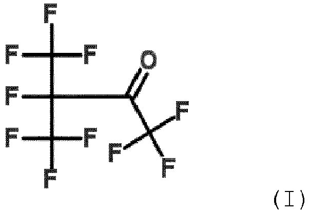
- the fluoroketone may more preferably be selected from the group consisting of: 1,1,1,3,4,4,4-heptafluoro-3-(trifluoromethyl)butan-2-one (also named decafluoro-2-methylbutan-3-one), 1,1,1,3,3,4,4,5,5,5-decafluoropentan-2-one, 1,1,1,2,2,4,4,5,5,5-decafluoropentan-3-one and octafluorocylcopentanone, and most preferably is 1,1,1,3,4,4,4-heptafluoro-3-(trifluoromethyl)butan-2-one.
- 1,1,1,3,4,4,4-heptafluoro-3-(trifluoromethyl)butan-2-one can be represented by the following structural formula (I): 1,1,1,3,4,4,4-heptafluoro-3-(trifluoromethyl)butan-2-one, herein briefly referred to as "C5K", with molecular formula CF 3 C(O)CF(CF 3 ) 2 or C 5 F 10 O, has been found to be particularly preferred for high and medium voltage insulation applications, because it has the advantages of high dielectric insulation performance, in particular in mixtures with a dielectric carrier gas, has very low GWP and has a low boiling point. It has an Ozone Depletion Potential (ODP) of 0 and is practically non-toxic.
- ODP Ozone Depletion Potential
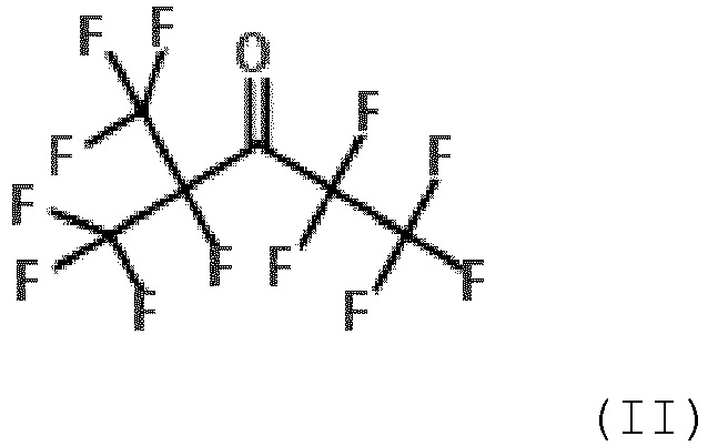
- the insulation medium can contain 1,1,1,2,4,4,5,5,5-nonafluoro-2-(trifluoromethyl) pentan-3-one (also named dodecafluoro-2-methylpentan-3-one), which can be represented by the following structural formula (II) : 1,1,1,2,4,4,5,5,5-Nonafluoro-4-(trifluoromethyl)pentan-3-one (here briefly referred to as "C6K”) with molecular formula C 2 F 5 C(O)CF(CF 3 ) 2 ) has been found to be particularly preferred for high voltage insulation applications because of its high insulating properties and its extremely low GWP.
- structural formula (II) 1,1,1,2,4,4,5,5,5-Nonafluoro-4-(trifluoromethyl)pentan-3-one (here briefly referred to as "C6K) with molecular formula C 2 F 5 C(O)CF(CF 3 ) 2 ) has been found to be particularly preferred for high voltage insulation applications because of its high
- the arc-quenching medium comprises at least one compound being a hydrofluoro-ether selected from the group consisting of: hydrofluoro monoether containing at least three carbon atoms; hydrofluoro monoether containing exactly three or exactly four carbon atoms; hydrofluoro monoether having a ratio of number of fluorine atoms to total number of fluorine and hydrogen atoms of at least 5:8; hydrofluoro monoether having a ratio of number of fluorine atoms to number of carbon atoms ranging from 1.5:1 to 2:1; pentafluoro-ethyl-methyl ether; 2,2,2-trifluoroethyl-trifluoromethyl ether; and mixtures thereof.
- hydrofluoro-ether selected from the group consisting of: hydrofluoro monoether containing at least three carbon atoms; hydrofluoro monoether containing exactly three or exactly four carbon atoms; hydrofluoro monoether having a ratio of number of fluorine atoms to total number of fluorine
- the arc-quenching medium can comprise a fluoronitrile as organofluorine compound, in particular a perfluoronitrile.
- the organofluorine compound can be a fluoronitrile, specifically a perfluoronitrile, containing two carbon atoms, three carbon atoms or four carbon atoms.
- the fluoronitrile can be a perfluoroalkylnitrile, specifically perfluoroacetonitrile, perfluoropropionitrile (C 2 F 5 CN) and/or perfluorobutyronitrile (C 3 F 7 CN).
- the fluoronitrile can be perfluoroisobutyronitrile (according to the formula (CF 3 ) 2 CFCN) and/or perfluoro-2-methoxypropane-nitrile (according to the formula CF 3 CF(OCF 3 )CN).
- perfluoroisobutyronitrile is particularly preferred due to its low toxicity.
- the arc-quenching medium can comprise a fluoroolefin, in particular a hydrofluoroolefin. More particularly, the fluoroolefin or hydrofluorolefin, respectively, contains at least three carbon atoms or contains exactly three carbon atoms.
- the hydrofluoroolefin is thus selected from the group consisting of: 1,1,1,2-tetrafluoropropene (HFO-1234yf; also named 2,3,3,3-tetrafluoro-1-propene), 1,2,3,3-tetrafluoro-2-propene (HFO-1234yc), 1,1,3,3-tetrafluoro-2-propene (HFO-1234zc), 1,1,1,3-tetrafluoro-2-propene (HFO-1234ze), 1,1,2,3-tetrafluoro-2-propene (HFO-1234ye), 1,1,1,2,3-pentafluoropropene (HFO-1225ye), 1,1,2,3,3-pentafluoropropene (HFO-1225yc), 1,1,1,3,3-pentafluoropropene (HFO-1225zc), (Z)1,1,1,3-tetrafluoropropene (HFO-1234zeZ);
- the device can be an earthing switch for a high voltage disconnector, which high voltage disconnector is designed for induced current switching, and in particular is rated for a current of 200 A at most and a voltage of 32 kV at most. Higher ratings may be addressed in the future, as well.
- Disconnectors using SF6 as arc-quenching medium are known in the art, but do not comprise any counter-arcing component according to the present invention.
- Counter-arcing components are nowhere suggested in the art, since the arc cooling properties of the arc-quenching gas is generally considered sufficient for extinguishing the arc under unblown conditions.
- the present invention also relates to a medium voltage or high voltage gas-insulated switchgear comprising a device as described above.
- the device of the present invention comprises two contacts 10, 12 movable in relation to each other, specifically a first contact 10 in the form of a tulip contact 101, which in the closed position engages around second contact 12 in the form of a plug contact 121.
- the tulip contact 101 is slideably contained in a guiding tube 14 forming a cylinder 16 having a continuous inner wall 18.
- the tulip contact 101 forms a piston 20, which together with the cylinder 16 defines a compression chamber 22 containing arc-quenching medium 17.
- a flow channel 24 is formed running in axially through the center of the piston 20.
- the compression chamber 22 is compressed by the piston 20, which moves in direction shown by the arrow in Fig. 1b , and the arc-quenching medium 17 contained in the compression chamber 22 is forced through the flow channel 24 fluidically connecting the compression chamber 22 with the arcing region 26.
- arc-extinction medium is ejected into the arcing region 26 at a relatively high blowing speed, which supports extinction of the arc 27.
- a differential pressure between the compression chamber 22 and the arcing region 26 is generated by slideably moving the piston 20 within the guiding tube 14 and hence compressing the compression chamber 22. This causes a flow of the arc-quenching medium 17 from the compression chamber 22 functioning as a flow-generating chamber 21 to the arcing region 26.
- the embodiment according to Fig. 1a, 1b thus comprises a counter-arcing component 19, which comprises a flow-generating chamber 21, in which the flow is generated by compression. Since by increasing the blowing speed, the arc is efficiently cooled, the counter-arcing component functions in this embodiment as an arc-cooling element.
- a first contact 10' is in the form of a tulip contact 101' in which the second contact 12' in the form of a plug contact 121' is contained.
- the tulip contact 101' forms a cylinder 16' in which the plug contact 121' forming a piston 20' is slideably moveable in a gas-tight manner.
- the piston 20' and the cylinder 16' together form a suction chamber 28 functioning as a flow-generating chamber 21'.
- the piston 20' can in particular comprise an electrically insulating nose 30.
- the arc 27 burns directly over the insulating nose 30, whereby additional over-pressure is generated by material ablation, which further contributes to an even higher differential pressure between the arcing region 26 and the suction chamber 28.
- the arc-quenching medium 17 thus flows into the suction chamber 28 at a very high flowing speed generated by the high differential pressure.
- a strong blowing effect is achieved by the arc-quenching medium 17 flowing at high speed across the arcing region 26, and extinction of the arc 27 is thereby supported.
- the embodiment shown in Fig. 3a, 3b comprises a first contact 10" in the form of a tulip contact 101" forming a cylinder 16", in which a second contact 12" in the form of a plug contact 121" forming a piston 20" is slideably moveable in a gas-tight manner. Also in this embodiment, the piston 20" and the cylinder 16" together form a suction chamber 28'', which functions as a flow-generating chamber 21".
- the piston 20" of Fig. 3a, 3b comprises in the region of its front end facing the tulip contact 101" a resistive element 32 which in axial direction of the piston 20" is sandwiched between two regions 34a, 34b of a lower-resistance material.
- the resistive element 32 In the closed state, the resistive element 32 is in parallel with the regions 34a, 34b of lower resistance, as schematically shown on the right hand side of Fig. 3a . As the resistance of resistive element 32 is much higher, the current flows through the lower-resistance regions 34a, 34b.
- the resistances R M and R M of the lower-resistance regions 34a, 34b and R R of the resistive element 32 get to be in series, as schematically shown on the right hand side of Fig. 3b , and are thus dominated by the resistance R R of the resistive element 32.
- the total resistance is thus given (in good approximation) by the sum of the resistances R R of the resistive element 32 and R arc of the arc 27.
- the current in this current path is low because of the resistive element 32, and hence the arc voltage drop may become higher than it would be without resistive element 32, which favourably supports arc extinction.
- a first contact 10''' is in the form of a tulip contact 101'''
- the second contact 12''' is in the form of a plug contact 121''', as for the embodiments shown above.
- the plug contact 121''' has a bulge 38, which holds the plug contact 121''' off from axial movement away from the tulip contact 101'''.
- a respective inward protrusion 40 is formed on the inside area 42 of the tulip contact 101'''.
Description
- The present invention relates to a device for interrupting non short-circuit currents only being an earthing switch, more particularly a make-proof earthing switch, as well as to a medium voltage or high voltage gas-insulated switchgear (GIS) comprising such a device.
- Dielectric insulation media in liquid or gaseous state are conventionally applied for the insulation of an electrically conductive part in a wide variety of apparatuses, and in particular also in GIS or components thereof.
- In medium or high voltage metal-encapsulated switchgears, for example, the electrically conductive part is arranged in a gas-tight housing, which defines an insulating space, said insulation space comprising an insulation gas and separating the housing from the electrically conductive part without allowing electrical currents to pass through the insulation space.
- For interrupting the current in e.g. high voltage switchgears, the insulating medium further functions as an arc-quenching medium (or arc-extinction medium). This is e.g. also the case in a disconnector or in an earthing switch, in which the arc generated during current interruption is extinguished under free-burning conditions, meaning that the arc-quenching medium is not actively blown towards the arc.
- In conventional gas-insulated switchgears, sulphur hexafluoride (SF6) is typically used as insulation medium and/or arc-quenching medium, respectively.
- Recently, the use of organofluorine compounds in an insulation medium has been suggested as a substitute for conventional insulation media. Specifically,
WO-A-2010/142346 discloses a dielectric insulation medium comprising a fluoroketone containing from 4 to 12 carbon atoms. Further,WO-A-2012/080246 discloses a fluoroketone containing exactly 5 carbon atoms (hereinafter referred to as "C5K") in a mixture with a dielectric insulation gas component different from said C5K to be particularly advantageous. The fluoroketones disclosed inWO-A-2010/142346 andWO-A-2012/080246 have been shown to have high insulation capabilities, in particular a high dielectric strength, as well as high arc extinction capabilities. At the same time, they have a very low Global Warming Potential (GWP) and very low toxicity. - Notwithstanding the above-mentioned excellent properties of a fluoroketone-containing insulation gas, it has unexpectedly been found that in a device designed for interrupting non-short circuit currents only, specifically in a disconnector or an earthing switch of a conventional design, interruption of even low currents could fail when using a fluoroketone-containing arc-quenching medium. This is due to the fluoroketone being present in relatively low concentrations in these devices, which goes along with relatively poor thermodynamic and transport properties and thus relatively poor cooling efficiency. The problem particularly applies to arc-quenching media that besides the organofluorine compound comprise a carrier or background gas, typically air or an air component. For example, tests have shown that an earthing switch, which repeatedly interrupts an inductive current of 80 A in several tens of miliseconds or less in SF6, failed to interrupt even lower currents in air and CO2 even after more than half a second of arcing, even though a correspondingly larger gap between the contacts has then been achieved.
- Thus, the favourable properties inherent to SF6, which allow efficient extinction of the arc at current-zero also at unblown conditions and which further ensure that the arc does not reignite, are not inherent to such gas mixtures containing organofluorine compounds.
-
WO 2013/153110 A1 discloses a circuit breaker which is capable of interrupting short-circuit currents and hence also non-short-circuit currents. - The problem of the present invention is to provide an improved device for interrupting non-short circuit currents only being an earthing switch, by using an arc-quenching medium containing an organofluorine compound, said device allowing at the same time a very reliable current interruption. This problem is solved by the subject matter of the independent claims. Embodiments are defined in dependent claims or claim combinations and in the description in conjunction with the drawings.
- According to the independent claims, the present invention relates to a device for interrupting non-short circuit currents only. Respective devices of the state of the art are designed such that the arc generated during interruption is conventionally extinguished by SF6 under unblown conditions, i.e. without actively inducing a gas flow of SF6 as arc-quenching medium.
- The device of the present invention comprises at least two contacts movable in relation to each other between a closed state and an open state and defining an arcing region, in which an arc is generated during a current interrupting operation and in which an arc-quenching medium comprising an organofluorine compound is present.
- According to the invention, a counter-arcing component is allocated to the arcing region, said counter-arcing component being designed for counteracting the generation of an arc and/or for supporting the extinction of an arc.
- As mentioned, the device of the present invention is designed for interrupting non-short circuit currents only. Particularly herein, the term "short-circuit currents", as opposed to non-short circuit currents, is thereby defined as currents that are established in the first, transient phase of up to approximately 3 seconds after the point in time, when from a grid operated under high voltage the parts under high voltage get connected to ground. According to this definition, the term "non short-circuit currents" relates to any currents not falling under the definition of "short-circuit currents" given above.
- A short circuit is an electrical circuit that allows a current to travel along an unintended path, often where essentially no or a very low electrical impedance is encountered. In general, such short-circuit currents must be interrupted within less than 5 seconds after their occurrence and preferably quicker (e.g. within less than 3 seconds) to prevent damages in electrical networks.
- According to the present invention, currents that flow from an electrical network (in particular high-voltage network or medium-voltage network) to ground via unintendend or intended paths and last longer than 3 seconds or longer than 5 seconds, are considered "non short-circuit currents". This definition of non-short-circuit currents is based on their duration only and is independent of their magnitude or the intendedness or unintendedness of their occurrence. In particular, this definition of non-short-circuit currents includes nominal currents and excludes short-circuit currents of shorter than 5 seconds duration.
- For example, such non-short-circuit currents can be currents that are induced between two parallel overhead lines, wherein one line is on both sides connected to ground and the other line is delivering current to loads. The non-short-circuit currents induced in the grounded overhead line can be interrupted by the devices according to the present invention.
- According to the invention, the device is an earthing switch, in particular a make-proof earthing switch.
- According to a further aspect, the present invention also relates to a low voltage circuit breaker comprising at least two contacts movable in relation to each other between a closed state and an open state and defining an arcing region, in which an arc is generated during a current interrupting operation and in which an arc-quenching medium comprising an organofluorine compound is present, wherein to the arcing region a counter-arcing component is allocated and is designed for counteracting the generation of an arc and/or for supporting the extinction of an arc.
- The present invention takes into account the surprising finding that inspite of the high dielectric insulation performance of the organofluorine compound, which is preferably used in combination with a carrier gas and more preferably with synthetic air or a gas mixture containing O2 and CO2, the cooling efficiency of an arc-quenching medium containing an organofluorine compound is often insufficient for efficient arc extinction under free-burning conditions.
- In contrast to conventional earthing switches, in which the cooling efficiency of the arc extinction medium (e.g. SF6) suffices to extinguish the arc under free-burning conditions, the cooling insufficiency of the organofluorine compound-containing arc-quenching medium is compensated for by the presence of the counter-arcing component.
- Consequently, potential arc extinction failures can reliably be circumvented also when using a non-SF6 arc-quenching medium comprising an organofluorine compound, which is favourable due to its environmental friendliness and low toxicity. Tus, the present invention allows using these non-SF6 quenching media in devices for interrupting non-short circuit currents only and ensures a very safe operation of these devices.
- It is understood that the embodiments described herein relate to the device for interrupting non-short circuit currents only being an earthing switch.
- According to embodiments, the counter-arcing component comprises or consists of an arc-cooling element for cooling the arc. In combination with the intrinsic cooling properties of the arc-quenching medium, a combined cooling effect is achieved that allows reliable current interruption.
- According to further embodiments, the counter-arcing component is designed to be activated during a relative movement of the contacts from closed state to open state.
- In particular embodiments, the counter-arcing component can comprise a flow-generating chamber, which is fluidically connected to the arcing region by a flow channel and which is designed such that during a relative movement of the contacts from a closed state to an open state a differential pressure is generated in the flow-generating chamber in relation to the arcing region, said differential pressure causing a flow of the arc-quenching medium between the arcing region and the flow-generating chamber to take place. According to this embodiment, the arc-quenching medium is blown into the arcing region only when the arc is generated, i.e. when the contacts are under voltage and are moved relative to each other from the closed state to the open state and form an arc in the arcing region between the contacts.
- According to a very straightforward preferred design, at least one of the contacts forms a piston, which is slideably contained by a guiding tube forming a cylinder, the piston together with the cylinder defining a compression chamber as the flow-generating chamber, said compression chamber being designed to be compressed during a relative movement of the contacts from a closed state to an open state. Specifically, the relative movement of the contacts is directly translated into a flow of the arc-quenching medium into the arcing region for extinction of the arc.
- According to the present invention, the connection between the arcing region and the compression chamber is such that during compression, the arc-quenching medium contained in the compression chamber is ejected into the arcing region.
- According to the present invention, the flow channel is formed axially within the piston. This allows for a very straightforward design and further ensures that the distance, which has to be passed by the arc-quenching medium from the compression chamber to the arcing region, is kept as short as possible.
- A particularly high blowing speed of the arc-quenching gas can be achieved, if a valve is allocated to the flow channel, said valve opening when a threshold differential pressure is exceeded. The differential pressure particularly relates to the pressure difference between the arcing region and the flow-generating chamber, in particular compression chamber.
- According to specific embodiments, the contact forming the piston is a plug contact designed to be slideably engaged within a tulip contact.
- According to further specific embodiments, the contact forming the piston is a tulip contact designed to engage around a plug contact. In this regard, the flow channel can be formed as a channel with circular cross-section running parallel to the axis of the tulip contact.
- For example, the flow channel is in the form of a flow gap arranged between the inner wall of the tulip contact and the outer wall of a cylindrical flow guide which is radially enclosed by the tulip contact in a spaced-apart manner. The flow channel according to this embodiment has in cross-section an annular form. More specifically, the inner wall of the tulip contact and the outer wall of a cylindrical flow guide run concentrically and parallel to each other, in which case the flow gap has a continuous cross-section over the axial length of the flow guide. More specifically, the flow guide can be formed as an insert fixed to the tulip contact. The presence of a flow guide allows to guide (or "steer") the flow of the arc-quenching medium in a manner such that an even more efficient cooling of the arc is achieved.
- Alternatively or additionally, the tulip contact is radially enclosed by a nozzle in a spaced-apart manner, thus forming a nozzle gap which opens out into the arcing region. The nozzle can in particular be a nozzle made of poly-tetrafluorethylene (PTFE; Teflon®).
- According to further embodiments, the contact forming the piston comprises a proximal contacting region and a distal compressing region arranged axially opposite to the contacting region, wherein the cross-sectional area of the compressing region is larger than the cross-sectional area of the contacting region. By the compressing region having a larger cross-sectional area, a higher pressure can be generated in the compression chamber, allowing for a high blowing speed of the arc-quenching medium and thus a high cooling efficiency to be achieved.
- According to still further embodiments, one of the contacts is in the form of a piston and is contained in the other contact, which forms a cylinder for the piston, and the piston is slideably moveable in the cylinder in a gas-tight manner. Thereby, the piston and the cylinder together form a suction chamber as the flow-generating chamber, said suction chamber being designed to increase in volume during a relative movement of the contacts from a closed state to an open state. Thus, flow of the arc-quenching medium to be blown into the arcing region is according to this embodiment generated by suction.
- In embodiments, the piston comprises in the region of its front end facing the other contact an electrically insulating nose, specifically in the form of an insulating plug. The insulating nose allows the differential pressure between the arcing region and the suction chamber to be further increased. Owing to the high differential pressure, very high blowing speeds of the arc-quenching medium can be achieved. In particular regarding this embodiment, a high speed of contact movement or stroke shall be provided. For this purpose, a spring element is preferably allocated to at least one moveable contact.
- With regard to the above described embodiments, in which the piston and the cylinder together form a suction chamber as the flow-generating chamber, the device can preferably further comprise a control volume designed to be expanded during a relative movement of the contacts from a closed state to an open state, said control volume being in the open state fluidically connected with the arcing region by at least one vent running through the wall of the cylinder. As the contact forming the cylinder, specifically the tulip contact, is pulled back, the arc-quenching medium is allowed to flow out through the vent; the building up of pressure within the cylinder, which might counteract the flow of arc-quenching medium, can thus be avoided. It is thereby particular preferred that the control volume is arranged radially outside of the cylinder.
- According to further embodiments, an ablating material, such as PTFE, is arranged adjacent to the contacts, the ablating material being designed to form ablation when exposed to an arc. When the arc is produced, it ablates the ablating material, specifically PTFE, which leads to additional pressure build-up in the arcing region. Without wanting to be bound by theory, it is further assumed that when the arc is produced, turbulence is created, which further cools the arc and hence enhances arc extinction.
- With regard to the above described embodiments, in which the flow-generating chamber is a compression chamber and a nozzle made of ablating material, in particular PTFE, is provided, the nozzle can further serve as a flow guide for guiding the arc-quenching medium to the arcing region for optimal cooling.
- With regard to the above described embodiments, in which the flow-generating chamber is a suction chamber and the ablating material preferably forms an electrically insulating nose, the arc burning directly over the insulating nose can generate additional over-pressure by material ablation, said over-pressure being proportional to the current. If in addition a nozzle is present, the nozzle can be shaped to adjust the flow in the nozzle region, which can be of advantage to avoid excessive pressure build up.
- Additionally or alternatively, the device can comprise as a counter-arcing component a magnet generating a permanent magnetic field in the arcing region. This allows the arc to be moved or rotated and also to be pushed out of the periphery, which causes longer arc lengths and thus higher arc voltage drops and thereby improves extinction of the arc. In specific embodiments, the magnet generates a permanent magnetic field in the arcing region.
- As also mentioned above, a spring element is preferably allocated to at least one moveable contact. In specific embodiments, the contacts are held off from transiting from a closed state to an open state by a holding force, and the spring element is designed to build up a spring force exceeding the holding force at a specific point in time. In particular, the one of the contacts can be in the form of a plug contact having a bulge, said bulge holding the plug contact off from axial movement by a respective inward protrusion formed on the other contact, typically a tulip contact. When the spring force exceeds a threshold value, the bulge forces the wall of the tulip contact towards an outward direction and thereby ultimately allows the plug contact to rebound axially out of the tulip contact. Thus, the moving contact, specifically the plug contact, is released at relatively high speed and further counteracts the generation of an arc and/or supports the extinction of an arc during current interruption.
- According to further embodiments, one of the contacts is in the form of a piston and is contained in the other contact, which forms a cylinder for the piston, and the piston is slideably moveable in the cylinder, wherein the piston comprises in the region of its front end facing the other contact a resistive element which in axial direction of the piston is sandwiched between two regions of a material of lower resistance. In the closed state, the resistive element is in parallel with the regions of lower resistance and, given that the resistance of the resistive element is much higher, the current flows through the regions of lower resistance. When moving the contacts from the closed state to the open state, the resistances of the resistive element and the regions of lower resistance are in series and are dominated by the resistance of the resistive element. During the arc formation, the total resistance is thus approximately given by the sum of the resistances of the resistive element and the arc. During the opening process, the current in the circuit is low because of the resistive element and hence the arc voltage is increased (compared to without resistive element), which is favourable for arc extinction.
- The effect achieved by the present invention is of particular relevance in embodiments, in which the arc-quenching medium further comprises air or at least one air component, in particular selected from the group consisting of: oxygen (O2) and nitrogen (N2), carbon dioxide (CO2), and mixtures thereof. The air or air component functions as a carrier gas or background gas additionally present to the organofluorine compound. As discussed above, the present invention achieves safe operation of the device despite of the relatively poor cooling efficiency of the carrier gas.
- According to embodiments, the arc-quenching medium comprises carbon dioxide and oxygen. It is thereby particularly preferred that the ratio of the amount of carbon dioxide to the amount of oxygen ranges from 50:50 to 100:1. It is further preferred that the ratio of the amount of carbon dioxide to the amount of oxygen ranges from 80:20 to 95:5, more preferably from 85:15 to 92:8, even more preferably from 87:13 to less than 90:10, and in particular is about 89:11. In this regard, it has been found on the one hand that oxygen being present in a molar fraction of at least 5% allows soot formation to be prevented even after repeated current interruption events with relatively high current arcing. On the other hand, oxygen being present in a molar fraction of at most 20% (i.e. of 20% or less), more particularly of at most 15% (i.e. of 15% or less), reduces the risk of degradation of the material of the device by oxidation.
- According to embodiments of the present invention, the organofluorine compound is selected from the group consisting of fluoroethers (including oxiranes), in particular hydrofluoromonoethers, fluoroketones, in particular perfluoroketones, fluoroolefins, in particular hydrofluoroolefins, fluoronitriles, in particular perfluoronitriles, and mixtures thereof.
- In embodiments, the arc-quenching medium can comprise a hydrofluoromonoether containing at least three carbon atoms. A more detailed description of such hydrofluoromonoethers is for example given in
WO 2012/080222 , the disclosure of which is hereby incorporated by reference in its entirety. - In embodiments, the arc-quenching medium can comprise a fluoroketone containing from four to twelve carbon atoms, preferably containing exactly five carbon atoms or exactly six carbon atoms, or a mixture thereof. A more detailed description of such fluoroketones is for example given in
WO 2010/142346 , the disclosure of which is hereby incorporated by reference in its entirety. - According to more specific embodiments, the fluoroketone is a perfluoroketone, and more particularly has the molecular formula C5F10O, i.e. it is fully saturated without any double or triple bonds between carbon atoms. The fluoroketone may more preferably be selected from the group consisting of: 1,1,1,3,4,4,4-heptafluoro-3-(trifluoromethyl)butan-2-one (also named decafluoro-2-methylbutan-3-one), 1,1,1,3,3,4,4,5,5,5-decafluoropentan-2-one, 1,1,1,2,2,4,4,5,5,5-decafluoropentan-3-one and octafluorocylcopentanone, and most preferably is 1,1,1,3,4,4,4-heptafluoro-3-(trifluoromethyl)butan-2-one. 1,1,1,3,4,4,4-heptafluoro-3-(trifluoromethyl)butan-2-one can be represented by the following structural formula (I):
- Additionally or alternatively, the insulation medium can contain 1,1,1,2,4,4,5,5,5-nonafluoro-2-(trifluoromethyl) pentan-3-one (also named dodecafluoro-2-methylpentan-3-one), which can be represented by the following structural formula (II) :
- In additional or alternative embodiments, the arc-quenching medium comprises at least one compound being a hydrofluoro-ether selected from the group consisting of: hydrofluoro monoether containing at least three carbon atoms; hydrofluoro monoether containing exactly three or exactly four carbon atoms; hydrofluoro monoether having a ratio of number of fluorine atoms to total number of fluorine and hydrogen atoms of at least 5:8; hydrofluoro monoether having a ratio of number of fluorine atoms to number of carbon atoms ranging from 1.5:1 to 2:1; pentafluoro-ethyl-methyl ether; 2,2,2-trifluoroethyl-trifluoromethyl ether; and mixtures thereof.
- Additionally or alternatively, the arc-quenching medium can comprise a fluoronitrile as organofluorine compound, in particular a perfluoronitrile. For example, the organofluorine compound can be a fluoronitrile, specifically a perfluoronitrile, containing two carbon atoms, three carbon atoms or four carbon atoms. More particularly, the fluoronitrile can be a perfluoroalkylnitrile, specifically perfluoroacetonitrile, perfluoropropionitrile (C2F5CN) and/or perfluorobutyronitrile (C3F7CN). Most particularly, the fluoronitrile can be perfluoroisobutyronitrile (according to the formula (CF3)2CFCN) and/or perfluoro-2-methoxypropane-nitrile (according to the formula CF3CF(OCF3)CN). Of these, perfluoroisobutyronitrile is particularly preferred due to its low toxicity.
- Additionally or alternatively, the arc-quenching medium can comprise a fluoroolefin, in particular a hydrofluoroolefin. More particularly, the fluoroolefin or hydrofluorolefin, respectively, contains at least three carbon atoms or contains exactly three carbon atoms. According to particularly preferred embodiments, the hydrofluoroolefin is thus selected from the group consisting of: 1,1,1,2-tetrafluoropropene (HFO-1234yf; also named 2,3,3,3-tetrafluoro-1-propene), 1,2,3,3-tetrafluoro-2-propene (HFO-1234yc), 1,1,3,3-tetrafluoro-2-propene (HFO-1234zc), 1,1,1,3-tetrafluoro-2-propene (HFO-1234ze), 1,1,2,3-tetrafluoro-2-propene (HFO-1234ye), 1,1,1,2,3-pentafluoropropene (HFO-1225ye), 1,1,2,3,3-pentafluoropropene (HFO-1225yc), 1,1,1,3,3-pentafluoropropene (HFO-1225zc), (Z)1,1,1,3-tetrafluoropropene (HFO-1234zeZ); also named cis-1,3,3,3-tetrafluoro-1-propene), (Z)1,1,2,3-tetrafluoro-2-propene (HFO-1234yeZ), (E)1,1,1,3-tetrafluoropropene (HFO-1234zeE; also named trans-1,3,3,3-tetrafluoro-1-propene), (E)1,1,2,3-tetrafluoro-2-propene (HFO-1234yeE), (Z)1,1,1,2,3-pentafluoropropene (HFO-1225yeZ; also named cis-1,2,3,3,3 pentafluoroprop-1-ene), (E)1,1,1,2,3-pentafluoropropene (HFO-1225yeE; also named trans-1,2,3,3,3 pentafluoroprop-1-ene), and mixtures thereof.
- The device can be an earthing switch for a high voltage disconnector, which high voltage disconnector is designed for induced current switching, and in particular is rated for a current of 200 A at most and a voltage of 32 kV at most. Higher ratings may be addressed in the future, as well.
- Disconnectors using SF6 as arc-quenching medium are known in the art, but do not comprise any counter-arcing component according to the present invention. Counter-arcing components are nowhere suggested in the art, since the arc cooling properties of the arc-quenching gas is generally considered sufficient for extinguishing the arc under unblown conditions.
- According to a further aspect, the present invention also relates to a medium voltage or high voltage gas-insulated switchgear comprising a device as described above.
- The present invention is further illustrated by way of the attached figures, of which:
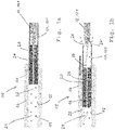
- Fig. 1a, 1b
- show schematically a counter-arcing component of a first embodiment of the device, the counter-arcing component being activated during a relative movement of the contacts from a closed state shown in
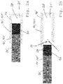
Fig. 1a to an open state shown inFig. 1b ; - Fig. 2a, 2b
- show schematically a counter-arcing component of a second embodiment of the device, the counter-arcing component being activated during a relative movement of the contacts from a closed state shown in
Fig. 2a to an open state shown inFig. 2b ; - Fig. 3a, 3b
- show schematically a counter-arcing component of a third embodiment of the device, the counter-arcing component being activated during a relative movement of the contacts from a closed state shown in
Fig. 3a to an open state shown inFig. 3b ; and - Fig. 4
- shows schematically two contacts of an exemplary device with a spring element being allocated to one of the contacts.
- As shown exemplarily in
Fig. 1 , the device of the present invention comprises twocontacts first contact 10 in the form of atulip contact 101, which in the closed position engages aroundsecond contact 12 in the form of aplug contact 121. - The
tulip contact 101 is slideably contained in a guidingtube 14 forming acylinder 16 having a continuousinner wall 18. Thus, thetulip contact 101 forms apiston 20, which together with thecylinder 16 defines acompression chamber 22 containing arc-quenchingmedium 17. Within thepiston 20, aflow channel 24 is formed running in axially through the center of thepiston 20. - During the movement of the
tulip contact 101 from the closed state shown inFig. 1a to the open state shown inFig. 1b , thecompression chamber 22 is compressed by thepiston 20, which moves in direction shown by the arrow inFig. 1b , and the arc-quenchingmedium 17 contained in thecompression chamber 22 is forced through theflow channel 24 fluidically connecting thecompression chamber 22 with the arcingregion 26. Thus, arc-extinction medium is ejected into the arcingregion 26 at a relatively high blowing speed, which supports extinction of thearc 27. - In other words, a differential pressure between the
compression chamber 22 and the arcingregion 26 is generated by slideably moving thepiston 20 within the guidingtube 14 and hence compressing thecompression chamber 22. This causes a flow of the arc-quenchingmedium 17 from thecompression chamber 22 functioning as a flow-generatingchamber 21 to the arcingregion 26. - The embodiment according to
Fig. 1a, 1b thus comprises acounter-arcing component 19, which comprises a flow-generatingchamber 21, in which the flow is generated by compression. Since by increasing the blowing speed, the arc is efficiently cooled, the counter-arcing component functions in this embodiment as an arc-cooling element. - According to the embodiment shown in
Fig. 2a, 2b , a first contact 10' is in the form of a tulip contact 101' in which the second contact 12' in the form of a plug contact 121' is contained. The tulip contact 101' forms a cylinder 16' in which the plug contact 121' forming a piston 20' is slideably moveable in a gas-tight manner. Thus, the piston 20' and the cylinder 16' together form asuction chamber 28 functioning as a flow-generating chamber 21'. - In the region of its front end facing the tulip contact 101', the piston 20' can in particular comprise an electrically insulating
nose 30. - During relative movement of the contacts 10', 12' from a closed state shown in
Fig. 2a to an open state shown inFig. 2b , the volume of thesuction chamber 28 is increased. At a certain point in the movement, the contacts 10', 12' become separated and the current is interrupted, but the insulatingnose 30 of the piston 20' still remains at least to a certain part inside thesuction chamber 28. By further moving the piston 20' in the direction away from the cylinder 16', the differential pressure is further increased, owing to the insulatingnose 30 functioning as a plug prohibiting pressure equalization. In this state, thearc 27 burns directly over the insulatingnose 30, whereby additional over-pressure is generated by material ablation, which further contributes to an even higher differential pressure between the arcingregion 26 and thesuction chamber 28. At the moment, when the insulatingnose 30 is finally released from the cylinder 16', the arc-quenchingmedium 17 thus flows into thesuction chamber 28 at a very high flowing speed generated by the high differential pressure. Ultimately, a strong blowing effect is achieved by the arc-quenchingmedium 17 flowing at high speed across the arcingregion 26, and extinction of thearc 27 is thereby supported. - Similarly to the embodiment shown in
Fig. 2a, 2b , also the embodiment shown inFig. 3a, 3b comprises afirst contact 10" in the form of atulip contact 101" forming acylinder 16", in which asecond contact 12" in the form of aplug contact 121" forming apiston 20" is slideably moveable in a gas-tight manner. Also in this embodiment, thepiston 20" and thecylinder 16" together form a suction chamber 28'', which functions as a flow-generatingchamber 21". - In distinction to the embodiment shown in
Fig. 2a, 2b , thepiston 20" ofFig. 3a, 3b comprises in the region of its front end facing thetulip contact 101" aresistive element 32 which in axial direction of thepiston 20" is sandwiched between tworegions 34a, 34b of a lower-resistance material. - In the closed state, the
resistive element 32 is in parallel with theregions 34a, 34b of lower resistance, as schematically shown on the right hand side ofFig. 3a . As the resistance ofresistive element 32 is much higher, the current flows through the lower-resistance regions 34a, 34b. When moving the contacts 10'', 12'' from the closed state shown inFig. 3a to the open state shown inFig. 3b , the resistances RM and RM of the lower-resistance regions 34a, 34b and RR of theresistive element 32 get to be in series, as schematically shown on the right hand side ofFig. 3b , and are thus dominated by the resistance RR of theresistive element 32. During formation of thearc 27, the total resistance is thus given (in good approximation) by the sum of the resistances RR of theresistive element 32 and Rarc of thearc 27. During the opening process, the current in this current path is low because of theresistive element 32, and hence the arc voltage drop may become higher than it would be withoutresistive element 32, which favourably supports arc extinction. - The blowing effect achieved by the device of the present invention, in particular of the embodiments shown above, can further be increased by a spring element as shown in
Fig. 4 . Therein, a first contact 10''' is in the form of a tulip contact 101''', whereas the second contact 12''' is in the form of a plug contact 121''', as for the embodiments shown above. However, in the embodiment ofFig. 4 , the plug contact 121''' has abulge 38, which holds the plug contact 121''' off from axial movement away from the tulip contact 101'''. To this end, a respectiveinward protrusion 40 is formed on theinside area 42 of the tulip contact 101'''. - When pulling the contacts 10''', 12''' in a direction away from each other, a point is achieved when the
spring force 36 or pullingforce 36 exceeds the holding force between the contacts 10''' or 101''' and 12'' or 121''', respectively. At this point, thebulge 38 forces thewall 41 of the tulip contact 101''' in an outward direction, ultimately allowing the plug contact 121''' to rebound axially out of the tulip contact 101'''. Thus, the plug contact 121''' is released at relatively high speed and further counteracts the generation of the arc and/or supports the extinction of the arc during current interruption. -
- 10, 101; 10', 101'; 10", 101"; 10''', 101'''
- first contact, tulip contact
- 12, 121; 12', 121'; 12", 121"; 12''', 121'''
- second contact, plug contact
- 14
- guiding tube
- 16, 16', 16"
- cylinder
- 17
- arc-quenching medium
- 18
- inner wall of cylinder
- 19
- counter-arcing component
- 20, 20', 20"
- piston
- 21, 21', 21"
- flow-generating chamber
- 22
- compression chamber
- 24
- flow channel
- 26
- arcing region
- 27
- arc
- 28, 28"
- suction chamber
- 30
- electrically insulating nose
- 32
- resistive element of resistance value RR
- 34a, 34b
- regions of piston made of material of lower resistance values RM
- 36
- spring element
- 38
- bulge
- 40
- inward protrusion
- 41
- wall of the tulip contact
- 42
- inside area of tulip contact
- Rarc
- arc resistance.
Claims (19)
- A device designed for interrupting non-short-circuit currents, the device comprising:at least two contacts (10, 12) movable in relation to each other between a closed state and an open state and defining an arcing region (26), in which an arc (27) is generated during a current interrupting operation and in which an arc-quenching medium (17) comprising an organofluorine compound is present,wherein a counter-arcing component (19) is allocated to the arcing region (26) and is designed for counteracting the generation of the arc (27) and/or is designed for supporting extinction of the arc (27),characterized in that the device is designed for interrupting non-short-circuit currents only and is an earthing switch,that at least one of the contacts (10, 12) forms a piston (20), which is slideably contained in a guiding tube (14) forming a cylinder (16) for the piston (20), the piston (20) together with the cylinder (16) defining a compression chamber (22) as a flow-generating chamber (21), said compression chamber (22) being designed to be compressed during a relative movement of the contacts (10, 12) from a closed state to an open state, ,the connection between the arcing region (26) and the compression chamber (22) being such that during compression, arc-quenching medium (17) contained in the compression chamber (22) is ejected into the arcing region (26), the flow channel (24) being formed axially within the piston (20).
- The device according to claim 1, wherein the device is a make-proof earthing switch.
- The device according to any one of the preceding claims, the counter-arcing component (19) comprising the flow-generating chamber (21), which is fluidically connected to the arcing region (26) by a flow channel (24) and which is designed such that during a relative movement of the contacts (10, 12) from a closed state to an open state a differential pressure is generated in the flow-generating chamber (21) in relation to the arcing region (26), said differential pressure causing a flow of the arc-quenching medium (17) between the arcing region (26) and the flow-generating chamber (21).
- The device according to claim 3, wherein to the flow channel (24) a valve is allocated, which opens when a threshold differential pressure is exceeded.
- The device according to any of the preceding claims, wherein the contact (10) forming the piston (20) is a tulip contact (101) designed to engage around a plug contact (12, 121) .
- The device according to claim 5, wherein the flow channel (24) is in the form of a flow gap arranged between the inner wall of the tulip contact (101) and the outer wall of a cylindrical flow guide which is radially enclosed by the tulip contact (101) in a spaced-apart manner; and/or wherein the tulip contact (101) is radially enclosed by a nozzle in a spaced-apart manner, thus forming a nozzle gap which opens out into the arcing region (26).
- The device according to any one of the claims 1 to 6, wherein the contact forming the piston (20) comprises a proximal contacting region and a distal compressing region arranged axially opposite to the contacting region, the cross-sectional area of the compressing region being larger than the cross-sectional area of the contacting region.
- A device designed for interrupting non-short-circuit currents, the device comprising:at least two contacts (10, 12) movable in relation to each other between a closed state and an open state and defining an arcing region (26), in which an arc (27) is generated during a current interrupting operation and in which an arc-quenching medium (17) comprising an organofluorine compound is present, wherein a counter-arcing component (19) is allocated to the arcing region (26) and is designed for counteracting the generation of the arc (27) and/or is designed for supporting extinction of the arc (27),characterized in that the device is designed for interrupting non-short-circuit currents only, andthat one of the contacts (10', 10"; 12', 12") is in the form of a piston (20', 20") contained by the other contact (12', 12"; 10', 10") forming a cylinder (16', 16") and being slideably moveable in the cylinder (16', 16") in a gas-tight manner, the piston (20', 20") and the cylinder (16', 16") together forming a suction chamber (28, 28") as the flow-generating chamber (21), said suction chamber (28, 28") being designed to increase in volume during a relative movement of the contacts (10', 10"; 12', 12") from a closed state to an open state.
- The device according to claim 8, wherein the contact (10', 10") forming the cylinder (16', 16") is a tulip contact (101', 101"); and/or wherein the piston (20') comprises an electrically insulating nose (30) in the region of its front end facing the other contact (10', 101'); and/or wherein it further comprises a control volume designed to be expanded during a relative movement of the contacts from a closed state to an open state, said control volume being in the open state fluidically connected with the arcing region by at least one vent running through the wall of the cylinder, in particular the control volume being arranged radially outside of the cylinder.
- The device according to any one of the preceding claims, wherein an ablating material is arranged adjacent to the contacts (10, 12), the ablating material being designed to form ablation when exposed to the arc (27); and/or the device comprises as a counter-arcing component (19) a magnet generating a permanent magnetic field in the arcing region (26) .
- The device according to any of the preceding claims, wherein a spring element (36) is allocated to at least one moveable contact (12‴, 121‴), in particular wherein the contacts (10‴, 101‴; 12‴, 121‴) are held off from a transition from a closed state to an open state by a holding force and the spring element (36) is designed to build up a pulling force exceeding the holding force.
- A device designed for interrupting non-short-circuit currents, the device comprising:at least two contacts (10, 12) movable in relation to each other between a closed state and an open state and defining an arcing region (26), in which an arc (27) is generated during a current interrupting operation and in which an arc-quenching medium (17) comprising an organofluorine compound is present,wherein a counter-arcing component (19) is allocated to the arcing region (26) and is designed for counteracting the generation of the arc (27) and/or is designed for supporting extinction of the arc (27), characterized inthat the device is designed for interrupting non-short-circuit currents only, andthat one of the contacts (10", 101"; 12", 121") is in the form of a piston (20") contained by the other contact (12", 121"; 10", 101") forming a cylinder (16") and being slideably moveable in the cylinder (16"), the piston (20") comprising in the region of its front end facing the other contact a resistive element (32) which in axial direction of the piston (20") is sandwiched between two regions (34a, 34b) of a material of lower resistance.
- The device according to any one of the preceding claims, wherein the arc-quenching medium (17) further comprises air or at least one air component, in particular selected from the group consisting of oxygen (O2) and nitrogen (N2), carbon dioxide (CO2), and mixtures thereof.
- The device according to claim 13, wherein the arc-quenching medium (17) comprises a mixture of carbon dioxide and oxygen, in particular wherein the ratio of the amount of carbon dioxide to the amount of oxygen ranges from 50:50 to 100:1, preferably from 80:20 to 95:5, more preferably from 85:15 to 92:8, even more preferably from 87:13 to less than 90:10, and in particular is about 89:11.
- The device according to any one of the preceding claims, wherein the organofluorine compound is selected from the group consisting of: fluoroethers, in particular hydrofluoromonoethers, fluoroketones, in particular perfluoroketones, fluoroolefins, in particular hydrofluoroolefins, and fluoronitriles, in particular perfluoronitriles, and mixtures thereof; in particular wherein the arc-quenching medium (17) comprises a fluoroketone containing from four to twelve carbon atoms, preferably containing exactly five carbon atoms or exactly six carbon atoms or mixtures thereof and/or wherein the arc-quenching medium (17) comprises a hydrofluoromonoether containing at least three carbon atoms.
- The device according to any one of claims 8 to 15, wherein it is a high voltage disconnector designed for bus charging, in particular rated for a current in the range from 0.1 A to 0.8 A and a voltage in the range from 72.5 kV to 800 kV; or it is an earthing switch of a high voltage disconnector designed for induced current switching, in particular rated for a current of 200 A at most and a voltage of 32 kV at most; or it is a high voltage disconnector designed for bus transfer switching, in particular rated for a current of 1.6 kA at most and a voltage in the range from 10 V to 40 V.
- The device according to any one of the preceding claims, wherein the device is different from a circuit breaker capable of interrupting short-circuit currents and the device is unable to interrupt short-circuit currents; and/or the device has means for interrupting the non-short-circuit currents and does not have means for interrupting short-circuit currents.
- The device according to any one of the preceding claims, wherein the non-short-circuit currents are currents that flow from an electrical network to ground via unintended or intended paths and last longer than 3 seconds, in particular longer than 5 seconds.
- A medium voltage or high voltage gas-insulated switchgear comprising a device as claimed in any one of the preceding claims.
Applications Claiming Priority (1)
| Application Number | Priority Date | Filing Date | Title |
|---|---|---|---|
| PCT/EP2015/057964 WO2016165733A1 (en) | 2015-04-13 | 2015-04-13 | Device for interrupting non-short circuit currents only, in particular disconnector or earthing switch |
Publications (3)
| Publication Number | Publication Date |
|---|---|
| EP3284098A1 EP3284098A1 (en) | 2018-02-21 |
| EP3284098B1 EP3284098B1 (en) | 2019-08-28 |
| EP3284098B2 true EP3284098B2 (en) | 2022-10-05 |
Family
ID=52823656
Family Applications (1)
| Application Number | Title | Priority Date | Filing Date |
|---|---|---|---|
| EP15715284.4A Active EP3284098B2 (en) | 2015-04-13 | 2015-04-13 | Device for interrupting non-short circuit currents only, in particular disconnector or earthing switch |
Country Status (5)
| Country | Link |
|---|---|
| US (3) | US10553376B2 (en) |
| EP (1) | EP3284098B2 (en) |
| CN (1) | CN107787516B (en) |
| ES (1) | ES2759262T5 (en) |
| WO (1) | WO2016165733A1 (en) |
Families Citing this family (6)
| Publication number | Priority date | Publication date | Assignee | Title |
|---|---|---|---|---|
| EP4141901A1 (en) * | 2021-08-26 | 2023-03-01 | Hitachi Energy Switzerland AG | Metal enclosed circuit breaker |
| CN114267569A (en) * | 2021-12-28 | 2022-04-01 | 中国航天空气动力技术研究院 | Auxiliary arc extinguishing system of direct-current quick circuit breaker |
| CN114420480B (en) * | 2022-01-06 | 2023-12-08 | 平高集团有限公司 | High-voltage switch equipment with isolation fracture and moving contact assembly thereof |
| EP4227968A1 (en) * | 2022-02-11 | 2023-08-16 | Hitachi Energy Switzerland AG | Fast earthing switch for interrupting non-short-circuit currents |
| US11862944B1 (en) | 2022-06-17 | 2024-01-02 | Jst Power Equipment, Inc. | Switchgear device with grounding device and related methods |
| CN116387079B (en) * | 2023-06-05 | 2023-09-19 | 浙江勇圣智能科技有限公司 | High-voltage isolating switch for high-voltage power transmission |
Citations (4)
| Publication number | Priority date | Publication date | Assignee | Title |
|---|---|---|---|---|
| KR200306995Y1 (en) † | 2002-12-10 | 2003-03-11 | 현대중공업 주식회사 | High Speed Grounding Switch |
| US7816618B2 (en) † | 2006-03-27 | 2010-10-19 | Kabushiki Kaisha Toshiba | Gas insulated switchgear |
| DE102009025204B3 (en) † | 2009-06-17 | 2010-11-25 | Ormazabal Gmbh | Switching device e.g. medium-voltage switching device, for use as block switchgear, has contact pieces and connecting pieces enclosed in packaging filled with filling medium that contains compound from group of perfluorinated ketone |
| DE102013205945A1 (en) † | 2013-04-04 | 2014-10-09 | Siemens Aktiengesellschaft | Disconnecting switch device |
Family Cites Families (53)
| Publication number | Priority date | Publication date | Assignee | Title |
|---|---|---|---|---|
| US3048683A (en) * | 1958-10-04 | 1962-08-07 | Forwald Haakon | Extinguishing chamber for oil circuit breaker |
| DE1665937A1 (en) * | 1967-04-28 | 1971-04-08 | Sachsenwerk Licht & Kraft Ag | Fire chamber for low-liquid electrical circuit breakers |
| US3832505A (en) | 1973-05-15 | 1974-08-27 | F Wong | Piston actuated switch with screw threads on piston and housing |
| DE2349331A1 (en) * | 1973-10-01 | 1975-04-03 | Bbc Brown Boveri & Cie | ELECTRIC SWITCH |
| US3991292A (en) * | 1974-10-10 | 1976-11-09 | Westinghouse Electric Corporation | Dual compression puffer interrupter |
| US4045633A (en) | 1975-06-27 | 1977-08-30 | General Electric Company | Gas-blast electric circuit interrupter of the puffer type |
| DE2708546C3 (en) * | 1977-02-28 | 1980-09-11 | Licentia Patent-Verwaltungs-Gmbh, 6000 Frankfurt | Autopneumatic pressurized gas circuit breaker |
| US4246459A (en) * | 1977-05-17 | 1981-01-20 | Tokyo Shibaura Denki Kabushiki Kaisha | Gas circuit breaker |
| DE2935673A1 (en) | 1978-09-04 | 1980-03-06 | Mitsubishi Electric Corp | SELF-CLEARING SWITCH |
| JPS56152129A (en) * | 1980-04-25 | 1981-11-25 | Mitsubishi Electric Corp | Buffer gas breaker |
| DE3142183A1 (en) | 1981-10-21 | 1983-04-28 | Siemens AG, 1000 Berlin und 8000 München | Contact system for high-voltage switches |
| US4459447A (en) * | 1982-01-27 | 1984-07-10 | Mitsubishi Denki Kabushiki Kaisha | Self extinguishing type gas circuit breaker |
| US4517425A (en) | 1983-09-14 | 1985-05-14 | Mcgraw-Edison Company | Self-flow generating gas interrupter |
| JPS63198145U (en) * | 1987-06-11 | 1988-12-20 | ||
| US4841108A (en) * | 1987-11-06 | 1989-06-20 | Cooper Industries, Inc. | Recloser plenum puffer interrupter |
| US5045651A (en) * | 1989-02-08 | 1991-09-03 | Hitachi, Ltd. | Switch |
| JP2997027B2 (en) | 1990-09-17 | 2000-01-11 | 株式会社日立製作所 | Gas insulated electrical equipment |
| JP2905330B2 (en) * | 1992-03-04 | 1999-06-14 | 三菱電機株式会社 | Disconnector |
| JPH09282982A (en) | 1996-04-18 | 1997-10-31 | Hitachi Ltd | Synchronous type gas-blast load breaker |
| JP2894314B2 (en) * | 1997-01-23 | 1999-05-24 | 日新電機株式会社 | Gas switch arc extinguishing device |
| DE19958645C5 (en) * | 1999-12-06 | 2011-05-26 | Abb Technology Ag | Hybrid circuit breaker |
| JP2003109481A (en) | 2002-09-20 | 2003-04-11 | Toshiba Corp | High-speed grounding switch |
| JP2004164994A (en) * | 2002-11-13 | 2004-06-10 | Toshiba Corp | Switch |
| JP2006164673A (en) * | 2004-12-06 | 2006-06-22 | Hitachi Ltd | Current breaking method of puffer type gas-blast circuit breaker and puffer type gas-blast circuit breaker using it |
| EP1913621A1 (en) | 2005-08-10 | 2008-04-23 | ABB Research Ltd | Self-blast circuit breaker with control body |
| CN101238534A (en) * | 2005-08-10 | 2008-08-06 | Abb研究有限公司 | Self-blast circuit breaker with control body |
| US7807074B2 (en) | 2006-12-12 | 2010-10-05 | Honeywell International Inc. | Gaseous dielectrics with low global warming potentials |
| WO2009049669A1 (en) * | 2007-10-16 | 2009-04-23 | Abb Research Ltd | Gas-insulated high-voltage circuit breaker with a relief duct which is controlled by an overflow valve |
| JP5127569B2 (en) * | 2008-05-29 | 2013-01-23 | 株式会社東芝 | Gas insulated switch |
| CN201315287Y (en) * | 2008-11-19 | 2009-09-23 | 平高集团有限公司 | Arc extinguish chamber of double-chamber thermal expanding self-extinguishing type SF6 circuit breaker and an air cylinder thereof |
| BRPI0924862A2 (en) | 2009-06-12 | 2016-08-23 | Abb Technology Ag | dielectric insulation medium |
| KR101053384B1 (en) | 2009-09-08 | 2011-08-01 | 주식회사 효성 | Load disconnector |
| US8350168B2 (en) * | 2010-06-30 | 2013-01-08 | Schneider Electric USA, Inc. | Quad break modular circuit breaker interrupter |
| BR112013014849A2 (en) | 2010-12-14 | 2016-10-18 | Abb Research Ltd | "Dielectric isolation medium, use of a hydrofluoric monoether, use of dielectric isolation medium and apparatus for the generation, distribution and use of electricity". |
| TWI574282B (en) | 2010-12-14 | 2017-03-11 | Abb科技公司 | Dielectric insulation medium, use of the dielectric insulation medium, apparatus for the generation and/or transmission and/or distribution and/or usage of electrical energy, and method for dimensioning an apparatus for the generation and/or transmission |
| US9035211B2 (en) * | 2011-07-20 | 2015-05-19 | Pennsylvania Breaker, Llc | Gas blast interrupter |
| WO2013087688A1 (en) | 2011-12-13 | 2013-06-20 | Abb Technology Ag | Circuit breaker with fluid injection |
| DE112013001981T5 (en) * | 2012-04-11 | 2015-03-12 | Abb Technology Ag | breakers |
| JP6157824B2 (en) * | 2012-09-28 | 2017-07-05 | 株式会社東芝 | Gas circuit breaker |
| FR2997222B1 (en) * | 2012-10-19 | 2015-01-16 | Alstom Technology Ltd | DEVICE FOR ESTABLISHING AND / OR CUTTING CURRENT WITH PERMANENT CONTACTS WITH REDUCED WEAR |
| WO2014092173A1 (en) * | 2012-12-14 | 2014-06-19 | 田中貴金属工業株式会社 | Rivet contact and method for manufacturing same |
| WO2014122814A1 (en) * | 2013-02-07 | 2014-08-14 | 三菱電機株式会社 | Arc-extinguishing insulating material molding and gas circuit breaker using same |
| TW201442051A (en) * | 2013-03-08 | 2014-11-01 | Hitachi Ltd | Gas blast circuit breaker |
| JP2014179301A (en) * | 2013-03-15 | 2014-09-25 | Toshiba Corp | Gas-insulated apparatus for electric power and method for operating the same |
| WO2014187940A1 (en) * | 2013-05-23 | 2014-11-27 | Abb Technology Ag | Electrical apparatus comprising a contamination-reducing component |
| MX2016008054A (en) * | 2013-12-23 | 2016-10-12 | Abb Technology Ag | Electrical switching device. |
| WO2015185095A1 (en) * | 2014-06-02 | 2015-12-10 | Abb Technology Ag | High voltage puffer breaker and a circuit breaker unit comprising such a puffer breaker |
| EP3237884B1 (en) * | 2014-12-23 | 2022-05-04 | Hitachi Energy Switzerland AG | Method for diagnosing, monitoring or predicting a condition of a switching apparatus |
| US9865418B2 (en) * | 2015-12-08 | 2018-01-09 | Siemens Industry, Inc. | Circuit breakers, arc expansion chambers, and operating methods |
| JP6818604B2 (en) * | 2017-03-24 | 2021-01-20 | 株式会社日立製作所 | Gas circuit breaker |
| EP3503152B1 (en) * | 2017-12-22 | 2020-10-14 | ABB Power Grids Switzerland AG | Gas-insulated high or medium voltage circuit breaker |
| US10872739B2 (en) * | 2019-05-24 | 2020-12-22 | Frank P Stacom | Methods and systems for DC current interrupter based on thermionic arc extinction via anode ion depletion |
| US11951542B2 (en) * | 2021-04-06 | 2024-04-09 | Eaton Intelligent Power Limited | Cold spray additive manufacturing of multi-material electrical contacts |
-
2015
- 2015-04-13 CN CN201580080892.3A patent/CN107787516B/en active Active
- 2015-04-13 WO PCT/EP2015/057964 patent/WO2016165733A1/en unknown
- 2015-04-13 ES ES15715284T patent/ES2759262T5/en active Active
- 2015-04-13 EP EP15715284.4A patent/EP3284098B2/en active Active
-
2017
- 2017-10-13 US US15/783,183 patent/US10553376B2/en active Active
-
2020
- 2020-01-27 US US16/773,297 patent/US11087939B2/en active Active
-
2021
- 2021-07-01 US US17/365,445 patent/US11699559B2/en active Active
Patent Citations (4)
| Publication number | Priority date | Publication date | Assignee | Title |
|---|---|---|---|---|
| KR200306995Y1 (en) † | 2002-12-10 | 2003-03-11 | 현대중공업 주식회사 | High Speed Grounding Switch |
| US7816618B2 (en) † | 2006-03-27 | 2010-10-19 | Kabushiki Kaisha Toshiba | Gas insulated switchgear |
| DE102009025204B3 (en) † | 2009-06-17 | 2010-11-25 | Ormazabal Gmbh | Switching device e.g. medium-voltage switching device, for use as block switchgear, has contact pieces and connecting pieces enclosed in packaging filled with filling medium that contains compound from group of perfluorinated ketone |
| DE102013205945A1 (en) † | 2013-04-04 | 2014-10-09 | Siemens Aktiengesellschaft | Disconnecting switch device |
Also Published As
| Publication number | Publication date |
|---|---|
| WO2016165733A1 (en) | 2016-10-20 |
| US20180040442A1 (en) | 2018-02-08 |
| CN107787516A (en) | 2018-03-09 |
| ES2759262T5 (en) | 2022-11-30 |
| EP3284098B1 (en) | 2019-08-28 |
| EP3284098A1 (en) | 2018-02-21 |
| US11087939B2 (en) | 2021-08-10 |
| US11699559B2 (en) | 2023-07-11 |
| US20210327665A1 (en) | 2021-10-21 |
| ES2759262T3 (en) | 2020-05-08 |
| US20200161064A1 (en) | 2020-05-21 |
| CN107787516B (en) | 2020-06-19 |
| US10553376B2 (en) | 2020-02-04 |
Similar Documents
| Publication | Publication Date | Title |
|---|---|---|
| US11699559B2 (en) | Device for interrupting non-short circuit currents only, in particular disconnector or earthing switch | |
| RU2738087C2 (en) | Gas isolated low or medium voltage load breaker | |
| EP4256596A1 (en) | Electrical switching device | |
| CN111630622B (en) | Gas-insulated high-or medium-voltage circuit breaker | |
| EP3261107A1 (en) | Gas-insulated low- or medium-voltage switch with swirling device | |
| CN111466006B (en) | Gas-insulated high-voltage or medium-voltage circuit breaker | |
| CN110770868B (en) | Gas-insulated load break switch and switchgear comprising a gas-insulated load break switch | |
| US20140174895A1 (en) | Contact arrangement for high voltage switchgear with contact arrangement | |
| EP3477675B1 (en) | Gas-insulated medium-voltage switch with shield device | |
| EP3826042B1 (en) | Arcing contact tulip with flow optimized slits and integrated stress relief feature | |
| EP4117006A1 (en) | Gas-insulated high or medium voltage circuit breaker | |
| EP4227968A1 (en) | Fast earthing switch for interrupting non-short-circuit currents | |
| EP4141901A1 (en) | Metal enclosed circuit breaker | |
| EP2827353A1 (en) | Electrical switching device | |
| DE202015009816U1 (en) | Device for interrupting only non-short-circuit currents, especially disconnectors or earthing switches |
Legal Events
| Date | Code | Title | Description |
|---|---|---|---|
| STAA | Information on the status of an ep patent application or granted ep patent |
Free format text: STATUS: THE INTERNATIONAL PUBLICATION HAS BEEN MADE |
|
| PUAI | Public reference made under article 153(3) epc to a published international application that has entered the european phase |
Free format text: ORIGINAL CODE: 0009012 |
|
| STAA | Information on the status of an ep patent application or granted ep patent |
Free format text: STATUS: REQUEST FOR EXAMINATION WAS MADE |
|
| 17P | Request for examination filed |
Effective date: 20171108 |
|
| AK | Designated contracting states |
Kind code of ref document: A1 Designated state(s): AL AT BE BG CH CY CZ DE DK EE ES FI FR GB GR HR HU IE IS IT LI LT LU LV MC MK MT NL NO PL PT RO RS SE SI SK SM TR |
|
| AX | Request for extension of the european patent |
Extension state: BA ME |
|
| DAV | Request for validation of the european patent (deleted) | ||
| DAX | Request for extension of the european patent (deleted) | ||
| GRAP | Despatch of communication of intention to grant a patent |
Free format text: ORIGINAL CODE: EPIDOSNIGR1 |
|
| STAA | Information on the status of an ep patent application or granted ep patent |
Free format text: STATUS: GRANT OF PATENT IS INTENDED |
|
| INTG | Intention to grant announced |
Effective date: 20190319 |
|
| GRAS | Grant fee paid |
Free format text: ORIGINAL CODE: EPIDOSNIGR3 |
|
| GRAA | (expected) grant |
Free format text: ORIGINAL CODE: 0009210 |
|
| STAA | Information on the status of an ep patent application or granted ep patent |
Free format text: STATUS: THE PATENT HAS BEEN GRANTED |
|
| AK | Designated contracting states |
Kind code of ref document: B1 Designated state(s): AL AT BE BG CH CY CZ DE DK EE ES FI FR GB GR HR HU IE IS IT LI LT LU LV MC MK MT NL NO PL PT RO RS SE SI SK SM TR |
|
| REG | Reference to a national code |
Ref country code: GB Ref legal event code: FG4D |
|
| RIN1 | Information on inventor provided before grant (corrected) |
Inventor name: CARSTENSEN, JAN Inventor name: SEEGER, MARTIN Inventor name: RANJAN, NITESH Inventor name: STOLLER, PATRICK Inventor name: TEHLAR, DENIS Inventor name: BUEHLER, RAFFAEL |
|
| REG | Reference to a national code |
Ref country code: CH Ref legal event code: EP |
|
| REG | Reference to a national code |
Ref country code: AT Ref legal event code: REF Ref document number: 1173418 Country of ref document: AT Kind code of ref document: T Effective date: 20190915 |
|
| REG | Reference to a national code |
Ref country code: IE Ref legal event code: FG4D |
|
| REG | Reference to a national code |
Ref country code: DE Ref legal event code: R096 Ref document number: 602015036661 Country of ref document: DE |
|
| REG | Reference to a national code |
Ref country code: NL Ref legal event code: MP Effective date: 20190828 |
|
| REG | Reference to a national code |
Ref country code: LT Ref legal event code: MG4D |
|
| PG25 | Lapsed in a contracting state [announced via postgrant information from national office to epo] |
Ref country code: NO Free format text: LAPSE BECAUSE OF FAILURE TO SUBMIT A TRANSLATION OF THE DESCRIPTION OR TO PAY THE FEE WITHIN THE PRESCRIBED TIME-LIMIT Effective date: 20191128 Ref country code: LT Free format text: LAPSE BECAUSE OF FAILURE TO SUBMIT A TRANSLATION OF THE DESCRIPTION OR TO PAY THE FEE WITHIN THE PRESCRIBED TIME-LIMIT Effective date: 20190828 Ref country code: BG Free format text: LAPSE BECAUSE OF FAILURE TO SUBMIT A TRANSLATION OF THE DESCRIPTION OR TO PAY THE FEE WITHIN THE PRESCRIBED TIME-LIMIT Effective date: 20191128 Ref country code: NL Free format text: LAPSE BECAUSE OF FAILURE TO SUBMIT A TRANSLATION OF THE DESCRIPTION OR TO PAY THE FEE WITHIN THE PRESCRIBED TIME-LIMIT Effective date: 20190828 Ref country code: FI Free format text: LAPSE BECAUSE OF FAILURE TO SUBMIT A TRANSLATION OF THE DESCRIPTION OR TO PAY THE FEE WITHIN THE PRESCRIBED TIME-LIMIT Effective date: 20190828 Ref country code: PT Free format text: LAPSE BECAUSE OF FAILURE TO SUBMIT A TRANSLATION OF THE DESCRIPTION OR TO PAY THE FEE WITHIN THE PRESCRIBED TIME-LIMIT Effective date: 20191230 Ref country code: HR Free format text: LAPSE BECAUSE OF FAILURE TO SUBMIT A TRANSLATION OF THE DESCRIPTION OR TO PAY THE FEE WITHIN THE PRESCRIBED TIME-LIMIT Effective date: 20190828 Ref country code: SE Free format text: LAPSE BECAUSE OF FAILURE TO SUBMIT A TRANSLATION OF THE DESCRIPTION OR TO PAY THE FEE WITHIN THE PRESCRIBED TIME-LIMIT Effective date: 20190828 |
|
| PG25 | Lapsed in a contracting state [announced via postgrant information from national office to epo] |
Ref country code: GR Free format text: LAPSE BECAUSE OF FAILURE TO SUBMIT A TRANSLATION OF THE DESCRIPTION OR TO PAY THE FEE WITHIN THE PRESCRIBED TIME-LIMIT Effective date: 20191129 Ref country code: LV Free format text: LAPSE BECAUSE OF FAILURE TO SUBMIT A TRANSLATION OF THE DESCRIPTION OR TO PAY THE FEE WITHIN THE PRESCRIBED TIME-LIMIT Effective date: 20190828 Ref country code: AL Free format text: LAPSE BECAUSE OF FAILURE TO SUBMIT A TRANSLATION OF THE DESCRIPTION OR TO PAY THE FEE WITHIN THE PRESCRIBED TIME-LIMIT Effective date: 20190828 Ref country code: IS Free format text: LAPSE BECAUSE OF FAILURE TO SUBMIT A TRANSLATION OF THE DESCRIPTION OR TO PAY THE FEE WITHIN THE PRESCRIBED TIME-LIMIT Effective date: 20191228 Ref country code: RS Free format text: LAPSE BECAUSE OF FAILURE TO SUBMIT A TRANSLATION OF THE DESCRIPTION OR TO PAY THE FEE WITHIN THE PRESCRIBED TIME-LIMIT Effective date: 20190828 |
|
| REG | Reference to a national code |
Ref country code: CH Ref legal event code: PUE Owner name: ABB POWER GRIDS SWITZERLAND AG, CH Free format text: FORMER OWNER: ABB SCHWEIZ AG, CH |
|
| REG | Reference to a national code |
Ref country code: AT Ref legal event code: MK05 Ref document number: 1173418 Country of ref document: AT Kind code of ref document: T Effective date: 20190828 |
|
| PG25 | Lapsed in a contracting state [announced via postgrant information from national office to epo] |
Ref country code: TR Free format text: LAPSE BECAUSE OF FAILURE TO SUBMIT A TRANSLATION OF THE DESCRIPTION OR TO PAY THE FEE WITHIN THE PRESCRIBED TIME-LIMIT Effective date: 20190828 |
|
| PG25 | Lapsed in a contracting state [announced via postgrant information from national office to epo] |
Ref country code: AT Free format text: LAPSE BECAUSE OF FAILURE TO SUBMIT A TRANSLATION OF THE DESCRIPTION OR TO PAY THE FEE WITHIN THE PRESCRIBED TIME-LIMIT Effective date: 20190828 Ref country code: DK Free format text: LAPSE BECAUSE OF FAILURE TO SUBMIT A TRANSLATION OF THE DESCRIPTION OR TO PAY THE FEE WITHIN THE PRESCRIBED TIME-LIMIT Effective date: 20190828 Ref country code: PL Free format text: LAPSE BECAUSE OF FAILURE TO SUBMIT A TRANSLATION OF THE DESCRIPTION OR TO PAY THE FEE WITHIN THE PRESCRIBED TIME-LIMIT Effective date: 20190828 Ref country code: EE Free format text: LAPSE BECAUSE OF FAILURE TO SUBMIT A TRANSLATION OF THE DESCRIPTION OR TO PAY THE FEE WITHIN THE PRESCRIBED TIME-LIMIT Effective date: 20190828 Ref country code: RO Free format text: LAPSE BECAUSE OF FAILURE TO SUBMIT A TRANSLATION OF THE DESCRIPTION OR TO PAY THE FEE WITHIN THE PRESCRIBED TIME-LIMIT Effective date: 20190828 |
|
| REG | Reference to a national code |
Ref country code: ES Ref legal event code: FG2A Ref document number: 2759262 Country of ref document: ES Kind code of ref document: T3 Effective date: 20200508 |
|
| REG | Reference to a national code |
Ref country code: DE Ref legal event code: R026 Ref document number: 602015036661 Country of ref document: DE |
|
| PG25 | Lapsed in a contracting state [announced via postgrant information from national office to epo] |
Ref country code: IS Free format text: LAPSE BECAUSE OF FAILURE TO SUBMIT A TRANSLATION OF THE DESCRIPTION OR TO PAY THE FEE WITHIN THE PRESCRIBED TIME-LIMIT Effective date: 20200224 Ref country code: SK Free format text: LAPSE BECAUSE OF FAILURE TO SUBMIT A TRANSLATION OF THE DESCRIPTION OR TO PAY THE FEE WITHIN THE PRESCRIBED TIME-LIMIT Effective date: 20190828 Ref country code: CZ Free format text: LAPSE BECAUSE OF FAILURE TO SUBMIT A TRANSLATION OF THE DESCRIPTION OR TO PAY THE FEE WITHIN THE PRESCRIBED TIME-LIMIT Effective date: 20190828 Ref country code: SM Free format text: LAPSE BECAUSE OF FAILURE TO SUBMIT A TRANSLATION OF THE DESCRIPTION OR TO PAY THE FEE WITHIN THE PRESCRIBED TIME-LIMIT Effective date: 20190828 |
|
| PLBI | Opposition filed |
Free format text: ORIGINAL CODE: 0009260 |
|
| PLAX | Notice of opposition and request to file observation + time limit sent |
Free format text: ORIGINAL CODE: EPIDOSNOBS2 |
|
| 26 | Opposition filed |
Opponent name: SIEMENS GAS AND POWER GMBH & CO. KG Effective date: 20200527 |
|
| PG2D | Information on lapse in contracting state deleted |
Ref country code: IS |
|
| RAP2 | Party data changed (patent owner data changed or rights of a patent transferred) |
Owner name: ABB POWER GRIDS SWITZERLAND AG |
|
| PG25 | Lapsed in a contracting state [announced via postgrant information from national office to epo] |
Ref country code: SI Free format text: LAPSE BECAUSE OF FAILURE TO SUBMIT A TRANSLATION OF THE DESCRIPTION OR TO PAY THE FEE WITHIN THE PRESCRIBED TIME-LIMIT Effective date: 20190828 |
|
| PLBB | Reply of patent proprietor to notice(s) of opposition received |
Free format text: ORIGINAL CODE: EPIDOSNOBS3 |
|
| PG25 | Lapsed in a contracting state [announced via postgrant information from national office to epo] |
Ref country code: MC Free format text: LAPSE BECAUSE OF FAILURE TO SUBMIT A TRANSLATION OF THE DESCRIPTION OR TO PAY THE FEE WITHIN THE PRESCRIBED TIME-LIMIT Effective date: 20190828 |
|
| PG25 | Lapsed in a contracting state [announced via postgrant information from national office to epo] |
Ref country code: LU Free format text: LAPSE BECAUSE OF NON-PAYMENT OF DUE FEES Effective date: 20200413 |
|
| REG | Reference to a national code |
Ref country code: BE Ref legal event code: MM Effective date: 20200430 |
|
| PLAB | Opposition data, opponent's data or that of the opponent's representative modified |
Free format text: ORIGINAL CODE: 0009299OPPO |
|
| PG25 | Lapsed in a contracting state [announced via postgrant information from national office to epo] |
Ref country code: BE Free format text: LAPSE BECAUSE OF NON-PAYMENT OF DUE FEES Effective date: 20200430 |
|
| R26 | Opposition filed (corrected) |
Opponent name: SIEMENS ENERGY GLOBAL GMBH & CO. KG Effective date: 20200527 |
|
| PG25 | Lapsed in a contracting state [announced via postgrant information from national office to epo] |
Ref country code: IE Free format text: LAPSE BECAUSE OF NON-PAYMENT OF DUE FEES Effective date: 20200413 |
|
| REG | Reference to a national code |
Ref country code: DE Ref legal event code: R081 Ref document number: 602015036661 Country of ref document: DE Owner name: HITACHI ENERGY SWITZERLAND AG, CH Free format text: FORMER OWNER: ABB SCHWEIZ AG, BADEN, CH Ref country code: DE Ref legal event code: R081 Ref document number: 602015036661 Country of ref document: DE Owner name: HITACHI ENERGY LTD, CH Free format text: FORMER OWNER: ABB SCHWEIZ AG, BADEN, CH Ref country code: DE Ref legal event code: R082 Ref document number: 602015036661 Country of ref document: DE Representative=s name: DENNEMEYER & ASSOCIATES S.A., DE Ref country code: DE Ref legal event code: R081 Ref document number: 602015036661 Country of ref document: DE Owner name: ABB POWER GRIDS SWITZERLAND AG, CH Free format text: FORMER OWNER: ABB SCHWEIZ AG, BADEN, CH |
|
| REG | Reference to a national code |
Ref country code: GB Ref legal event code: 732E Free format text: REGISTERED BETWEEN 20211104 AND 20211110 |
|
| RAP4 | Party data changed (patent owner data changed or rights of a patent transferred) |
Owner name: HITACHI ENERGY SWITZERLAND AG |
|
| APBM | Appeal reference recorded |
Free format text: ORIGINAL CODE: EPIDOSNREFNO |
|
| APBP | Date of receipt of notice of appeal recorded |
Free format text: ORIGINAL CODE: EPIDOSNNOA2O |
|
| APAH | Appeal reference modified |
Free format text: ORIGINAL CODE: EPIDOSCREFNO |
|
| APBU | Appeal procedure closed |
Free format text: ORIGINAL CODE: EPIDOSNNOA9O |
|
| PG25 | Lapsed in a contracting state [announced via postgrant information from national office to epo] |
Ref country code: MT Free format text: LAPSE BECAUSE OF FAILURE TO SUBMIT A TRANSLATION OF THE DESCRIPTION OR TO PAY THE FEE WITHIN THE PRESCRIBED TIME-LIMIT Effective date: 20190828 Ref country code: CY Free format text: LAPSE BECAUSE OF FAILURE TO SUBMIT A TRANSLATION OF THE DESCRIPTION OR TO PAY THE FEE WITHIN THE PRESCRIBED TIME-LIMIT Effective date: 20190828 |
|
| REG | Reference to a national code |
Ref country code: DE Ref legal event code: R081 Ref document number: 602015036661 Country of ref document: DE Owner name: HITACHI ENERGY SWITZERLAND AG, CH Free format text: FORMER OWNER: ABB POWER GRIDS SWITZERLAND AG, BADEN, CH Ref country code: DE Ref legal event code: R081 Ref document number: 602015036661 Country of ref document: DE Owner name: HITACHI ENERGY LTD, CH Free format text: FORMER OWNER: ABB POWER GRIDS SWITZERLAND AG, BADEN, CH |
|
| PG25 | Lapsed in a contracting state [announced via postgrant information from national office to epo] |
Ref country code: MK Free format text: LAPSE BECAUSE OF FAILURE TO SUBMIT A TRANSLATION OF THE DESCRIPTION OR TO PAY THE FEE WITHIN THE PRESCRIBED TIME-LIMIT Effective date: 20190828 |
|
| PUAH | Patent maintained in amended form |
Free format text: ORIGINAL CODE: 0009272 |
|
| STAA | Information on the status of an ep patent application or granted ep patent |
Free format text: STATUS: PATENT MAINTAINED AS AMENDED |
|
| 27A | Patent maintained in amended form |
Effective date: 20221005 |
|
| AK | Designated contracting states |
Kind code of ref document: B2 Designated state(s): AL AT BE BG CH CY CZ DE DK EE ES FI FR GB GR HR HU IE IS IT LI LT LU LV MC MK MT NL NO PL PT RO RS SE SI SK SM TR |
|
| REG | Reference to a national code |
Ref country code: DE Ref legal event code: R102 Ref document number: 602015036661 Country of ref document: DE |
|
| REG | Reference to a national code |
Ref country code: ES Ref legal event code: DC2A Ref document number: 2759262 Country of ref document: ES Kind code of ref document: T5 Effective date: 20221130 |
|
| P01 | Opt-out of the competence of the unified patent court (upc) registered |
Effective date: 20230527 |
|
| PGFP | Annual fee paid to national office [announced via postgrant information from national office to epo] |
Ref country code: IT Payment date: 20230426 Year of fee payment: 9 Ref country code: FR Payment date: 20230424 Year of fee payment: 9 Ref country code: ES Payment date: 20230627 Year of fee payment: 9 Ref country code: DE Payment date: 20230420 Year of fee payment: 9 Ref country code: CH Payment date: 20230502 Year of fee payment: 9 |
|
| PGFP | Annual fee paid to national office [announced via postgrant information from national office to epo] |
Ref country code: GB Payment date: 20230419 Year of fee payment: 9 |
|
| REG | Reference to a national code |
Ref country code: DE Ref legal event code: R082 Ref document number: 602015036661 Country of ref document: DE Representative=s name: DENNEMEYER & ASSOCIATES S.A., DE Ref country code: DE Ref legal event code: R081 Ref document number: 602015036661 Country of ref document: DE Owner name: HITACHI ENERGY LTD, CH Free format text: FORMER OWNER: HITACHI ENERGY SWITZERLAND AG, BADEN, CH |