EP3283879B1 - Method for detecting one or more analytes in a sample, said detection being delimited by a reaction chamber - Google Patents
Method for detecting one or more analytes in a sample, said detection being delimited by a reaction chamber Download PDFInfo
- Publication number
- EP3283879B1 EP3283879B1 EP16716580.2A EP16716580A EP3283879B1 EP 3283879 B1 EP3283879 B1 EP 3283879B1 EP 16716580 A EP16716580 A EP 16716580A EP 3283879 B1 EP3283879 B1 EP 3283879B1
- Authority
- EP
- European Patent Office
- Prior art keywords
- reaction
- microparticles
- reaction solution
- microparticle
- signal amplification
- Prior art date
- Legal status (The legal status is an assumption and is not a legal conclusion. Google has not performed a legal analysis and makes no representation as to the accuracy of the status listed.)
- Active
Links
- 238000006243 chemical reaction Methods 0.000 title claims description 683
- 238000000034 method Methods 0.000 title claims description 132
- 238000001514 detection method Methods 0.000 title claims description 115
- 239000011859 microparticle Substances 0.000 claims description 611
- 238000003199 nucleic acid amplification method Methods 0.000 claims description 201
- 230000003321 amplification Effects 0.000 claims description 200
- 239000012491 analyte Substances 0.000 claims description 187
- 239000007795 chemical reaction product Substances 0.000 claims description 106
- 239000011230 binding agent Substances 0.000 claims description 88
- 238000005259 measurement Methods 0.000 claims description 84
- 239000000758 substrate Substances 0.000 claims description 71
- 102000004190 Enzymes Human genes 0.000 claims description 64
- 108090000790 Enzymes Proteins 0.000 claims description 64
- 230000000694 effects Effects 0.000 claims description 33
- 239000002245 particle Substances 0.000 claims description 32
- 102000003992 Peroxidases Human genes 0.000 claims description 30
- 108020004414 DNA Proteins 0.000 claims description 28
- 230000027455 binding Effects 0.000 claims description 28
- 150000007523 nucleic acids Chemical class 0.000 claims description 28
- 230000002255 enzymatic effect Effects 0.000 claims description 27
- 102000039446 nucleic acids Human genes 0.000 claims description 24
- 108020004707 nucleic acids Proteins 0.000 claims description 24
- 239000002105 nanoparticle Substances 0.000 claims description 23
- 239000000203 mixture Substances 0.000 claims description 21
- 238000003018 immunoassay Methods 0.000 claims description 17
- 230000002441 reversible effect Effects 0.000 claims description 17
- 238000003556 assay Methods 0.000 claims description 12
- 230000006641 stabilisation Effects 0.000 claims description 12
- 102000035195 Peptidases Human genes 0.000 claims description 10
- 108091005804 Peptidases Proteins 0.000 claims description 10
- 238000009396 hybridization Methods 0.000 claims description 10
- 238000000338 in vitro Methods 0.000 claims description 7
- 239000000047 product Substances 0.000 claims description 7
- 235000019833 protease Nutrition 0.000 claims description 7
- 102000004316 Oxidoreductases Human genes 0.000 claims description 6
- 108090000854 Oxidoreductases Proteins 0.000 claims description 6
- 238000006911 enzymatic reaction Methods 0.000 claims description 6
- 239000011148 porous material Substances 0.000 claims description 5
- 108010014303 DNA-directed DNA polymerase Proteins 0.000 claims description 4
- 102000016928 DNA-directed DNA polymerase Human genes 0.000 claims description 4
- 102000004163 DNA-directed RNA polymerases Human genes 0.000 claims description 4
- 108090000626 DNA-directed RNA polymerases Proteins 0.000 claims description 4
- 102100034343 Integrase Human genes 0.000 claims description 4
- 102000045595 Phosphoprotein Phosphatases Human genes 0.000 claims description 4
- 108700019535 Phosphoprotein Phosphatases Proteins 0.000 claims description 4
- 108010092799 RNA-directed DNA polymerase Proteins 0.000 claims description 4
- 102000005744 Glycoside Hydrolases Human genes 0.000 claims description 3
- 108010031186 Glycoside Hydrolases Proteins 0.000 claims description 3
- 102000003960 Ligases Human genes 0.000 claims description 3
- 108090000364 Ligases Proteins 0.000 claims description 3
- 102000004882 Lipase Human genes 0.000 claims description 3
- 108090001060 Lipase Proteins 0.000 claims description 3
- 239000004367 Lipase Substances 0.000 claims description 3
- 108060001084 Luciferase Proteins 0.000 claims description 3
- 108091028043 Nucleic acid sequence Proteins 0.000 claims description 3
- 108700020962 Peroxidase Proteins 0.000 claims description 3
- 239000004365 Protease Substances 0.000 claims description 3
- 108091007187 Reductases Proteins 0.000 claims description 3
- 102000004357 Transferases Human genes 0.000 claims description 3
- 108090000992 Transferases Proteins 0.000 claims description 3
- 235000019421 lipase Nutrition 0.000 claims description 3
- 125000006850 spacer group Chemical group 0.000 claims description 3
- 239000012530 fluid Substances 0.000 claims description 2
- 238000012216 screening Methods 0.000 claims description 2
- 238000000151 deposition Methods 0.000 claims 2
- 108091032973 (ribonucleotides)n+m Proteins 0.000 claims 1
- 239000000243 solution Substances 0.000 description 233
- 239000000523 sample Substances 0.000 description 210
- 238000004422 calculation algorithm Methods 0.000 description 57
- 238000003752 polymerase chain reaction Methods 0.000 description 47
- 239000007850 fluorescent dye Substances 0.000 description 44
- 239000007788 liquid Substances 0.000 description 34
- 239000013598 vector Substances 0.000 description 29
- 230000008569 process Effects 0.000 description 28
- 102000053602 DNA Human genes 0.000 description 27
- 230000003287 optical effect Effects 0.000 description 27
- 108040007629 peroxidase activity proteins Proteins 0.000 description 27
- 108091034117 Oligonucleotide Proteins 0.000 description 24
- 238000011156 evaluation Methods 0.000 description 24
- 238000000576 coating method Methods 0.000 description 21
- 238000010791 quenching Methods 0.000 description 21
- 239000011248 coating agent Substances 0.000 description 20
- 239000000463 material Substances 0.000 description 20
- 238000005406 washing Methods 0.000 description 20
- 229960002685 biotin Drugs 0.000 description 19
- 239000011616 biotin Substances 0.000 description 19
- 238000004364 calculation method Methods 0.000 description 19
- 230000000171 quenching effect Effects 0.000 description 19
- 238000005119 centrifugation Methods 0.000 description 18
- 238000009792 diffusion process Methods 0.000 description 18
- 230000005284 excitation Effects 0.000 description 18
- 238000003384 imaging method Methods 0.000 description 18
- 239000002679 microRNA Substances 0.000 description 18
- 108090001008 Avidin Proteins 0.000 description 17
- 108700011259 MicroRNAs Proteins 0.000 description 16
- 238000010521 absorption reaction Methods 0.000 description 16
- 230000015572 biosynthetic process Effects 0.000 description 15
- 210000004027 cell Anatomy 0.000 description 15
- 239000000975 dye Substances 0.000 description 15
- 108090000765 processed proteins & peptides Proteins 0.000 description 15
- 239000000126 substance Substances 0.000 description 15
- 230000008859 change Effects 0.000 description 14
- 238000004020 luminiscence type Methods 0.000 description 14
- 238000012360 testing method Methods 0.000 description 14
- 108010090804 Streptavidin Proteins 0.000 description 13
- 230000007423 decrease Effects 0.000 description 13
- 230000035945 sensitivity Effects 0.000 description 13
- 210000002966 serum Anatomy 0.000 description 13
- 238000004458 analytical method Methods 0.000 description 12
- 230000000295 complement effect Effects 0.000 description 12
- 230000009977 dual effect Effects 0.000 description 12
- JLCPHMBAVCMARE-UHFFFAOYSA-N [3-[[3-[[3-[[3-[[3-[[3-[[3-[[3-[[3-[[3-[[3-[[5-(2-amino-6-oxo-1H-purin-9-yl)-3-[[3-[[3-[[3-[[3-[[3-[[5-(2-amino-6-oxo-1H-purin-9-yl)-3-[[5-(2-amino-6-oxo-1H-purin-9-yl)-3-hydroxyoxolan-2-yl]methoxy-hydroxyphosphoryl]oxyoxolan-2-yl]methoxy-hydroxyphosphoryl]oxy-5-(5-methyl-2,4-dioxopyrimidin-1-yl)oxolan-2-yl]methoxy-hydroxyphosphoryl]oxy-5-(6-aminopurin-9-yl)oxolan-2-yl]methoxy-hydroxyphosphoryl]oxy-5-(6-aminopurin-9-yl)oxolan-2-yl]methoxy-hydroxyphosphoryl]oxy-5-(6-aminopurin-9-yl)oxolan-2-yl]methoxy-hydroxyphosphoryl]oxy-5-(6-aminopurin-9-yl)oxolan-2-yl]methoxy-hydroxyphosphoryl]oxyoxolan-2-yl]methoxy-hydroxyphosphoryl]oxy-5-(5-methyl-2,4-dioxopyrimidin-1-yl)oxolan-2-yl]methoxy-hydroxyphosphoryl]oxy-5-(4-amino-2-oxopyrimidin-1-yl)oxolan-2-yl]methoxy-hydroxyphosphoryl]oxy-5-(5-methyl-2,4-dioxopyrimidin-1-yl)oxolan-2-yl]methoxy-hydroxyphosphoryl]oxy-5-(5-methyl-2,4-dioxopyrimidin-1-yl)oxolan-2-yl]methoxy-hydroxyphosphoryl]oxy-5-(6-aminopurin-9-yl)oxolan-2-yl]methoxy-hydroxyphosphoryl]oxy-5-(6-aminopurin-9-yl)oxolan-2-yl]methoxy-hydroxyphosphoryl]oxy-5-(4-amino-2-oxopyrimidin-1-yl)oxolan-2-yl]methoxy-hydroxyphosphoryl]oxy-5-(4-amino-2-oxopyrimidin-1-yl)oxolan-2-yl]methoxy-hydroxyphosphoryl]oxy-5-(4-amino-2-oxopyrimidin-1-yl)oxolan-2-yl]methoxy-hydroxyphosphoryl]oxy-5-(6-aminopurin-9-yl)oxolan-2-yl]methoxy-hydroxyphosphoryl]oxy-5-(4-amino-2-oxopyrimidin-1-yl)oxolan-2-yl]methyl [5-(6-aminopurin-9-yl)-2-(hydroxymethyl)oxolan-3-yl] hydrogen phosphate Polymers Cc1cn(C2CC(OP(O)(=O)OCC3OC(CC3OP(O)(=O)OCC3OC(CC3O)n3cnc4c3nc(N)[nH]c4=O)n3cnc4c3nc(N)[nH]c4=O)C(COP(O)(=O)OC3CC(OC3COP(O)(=O)OC3CC(OC3COP(O)(=O)OC3CC(OC3COP(O)(=O)OC3CC(OC3COP(O)(=O)OC3CC(OC3COP(O)(=O)OC3CC(OC3COP(O)(=O)OC3CC(OC3COP(O)(=O)OC3CC(OC3COP(O)(=O)OC3CC(OC3COP(O)(=O)OC3CC(OC3COP(O)(=O)OC3CC(OC3COP(O)(=O)OC3CC(OC3COP(O)(=O)OC3CC(OC3COP(O)(=O)OC3CC(OC3COP(O)(=O)OC3CC(OC3COP(O)(=O)OC3CC(OC3COP(O)(=O)OC3CC(OC3CO)n3cnc4c(N)ncnc34)n3ccc(N)nc3=O)n3cnc4c(N)ncnc34)n3ccc(N)nc3=O)n3ccc(N)nc3=O)n3ccc(N)nc3=O)n3cnc4c(N)ncnc34)n3cnc4c(N)ncnc34)n3cc(C)c(=O)[nH]c3=O)n3cc(C)c(=O)[nH]c3=O)n3ccc(N)nc3=O)n3cc(C)c(=O)[nH]c3=O)n3cnc4c3nc(N)[nH]c4=O)n3cnc4c(N)ncnc34)n3cnc4c(N)ncnc34)n3cnc4c(N)ncnc34)n3cnc4c(N)ncnc34)O2)c(=O)[nH]c1=O JLCPHMBAVCMARE-UHFFFAOYSA-N 0.000 description 11
- -1 antibody Proteins 0.000 description 11
- 108091007433 antigens Proteins 0.000 description 11
- 102000036639 antigens Human genes 0.000 description 11
- 239000003153 chemical reaction reagent Substances 0.000 description 11
- 239000002480 mineral oil Substances 0.000 description 11
- 235000010446 mineral oil Nutrition 0.000 description 11
- 102000004196 processed proteins & peptides Human genes 0.000 description 11
- 239000011541 reaction mixture Substances 0.000 description 11
- PYWVYCXTNDRMGF-UHFFFAOYSA-N rhodamine B Chemical compound [Cl-].C=12C=CC(=[N+](CC)CC)C=C2OC2=CC(N(CC)CC)=CC=C2C=1C1=CC=CC=C1C(O)=O PYWVYCXTNDRMGF-UHFFFAOYSA-N 0.000 description 11
- 238000011105 stabilization Methods 0.000 description 11
- 239000000725 suspension Substances 0.000 description 11
- LMDZBCPBFSXMTL-UHFFFAOYSA-N 1-ethyl-3-(3-dimethylaminopropyl)carbodiimide Chemical compound CCN=C=NCCCN(C)C LMDZBCPBFSXMTL-UHFFFAOYSA-N 0.000 description 10
- 239000000427 antigen Substances 0.000 description 10
- 238000011534 incubation Methods 0.000 description 10
- 238000000926 separation method Methods 0.000 description 10
- QWZHDKGQKYEBKK-UHFFFAOYSA-N 3-aminochromen-2-one Chemical compound C1=CC=C2OC(=O)C(N)=CC2=C1 QWZHDKGQKYEBKK-UHFFFAOYSA-N 0.000 description 9
- PEDCQBHIVMGVHV-UHFFFAOYSA-N Glycerine Chemical compound OCC(O)CO PEDCQBHIVMGVHV-UHFFFAOYSA-N 0.000 description 9
- 241000282414 Homo sapiens Species 0.000 description 9
- 230000008901 benefit Effects 0.000 description 9
- 238000002073 fluorescence micrograph Methods 0.000 description 9
- 125000000524 functional group Chemical group 0.000 description 9
- 229920000642 polymer Polymers 0.000 description 9
- 239000002253 acid Substances 0.000 description 8
- 238000013459 approach Methods 0.000 description 8
- 201000010099 disease Diseases 0.000 description 8
- 208000037265 diseases, disorders, signs and symptoms Diseases 0.000 description 8
- 230000005291 magnetic effect Effects 0.000 description 8
- 230000004048 modification Effects 0.000 description 8
- 238000012986 modification Methods 0.000 description 8
- 239000002773 nucleotide Substances 0.000 description 8
- 108090000623 proteins and genes Proteins 0.000 description 8
- 238000011002 quantification Methods 0.000 description 8
- 238000003753 real-time PCR Methods 0.000 description 8
- 230000002829 reductive effect Effects 0.000 description 8
- 229920002477 rna polymer Polymers 0.000 description 8
- 108091093088 Amplicon Proteins 0.000 description 7
- 239000004793 Polystyrene Substances 0.000 description 7
- 229920002125 Sokalan® Polymers 0.000 description 7
- 239000000969 carrier Substances 0.000 description 7
- 238000009826 distribution Methods 0.000 description 7
- 239000003094 microcapsule Substances 0.000 description 7
- 230000005298 paramagnetic effect Effects 0.000 description 7
- 239000012071 phase Substances 0.000 description 7
- 239000004584 polyacrylic acid Substances 0.000 description 7
- 229920002223 polystyrene Polymers 0.000 description 7
- 238000012545 processing Methods 0.000 description 7
- 239000013074 reference sample Substances 0.000 description 7
- YBJHBAHKTGYVGT-ZKWXMUAHSA-N (+)-Biotin Chemical compound N1C(=O)N[C@@H]2[C@H](CCCCC(=O)O)SC[C@@H]21 YBJHBAHKTGYVGT-ZKWXMUAHSA-N 0.000 description 6
- 229920001410 Microfiber Polymers 0.000 description 6
- 229920001213 Polysorbate 20 Polymers 0.000 description 6
- 102000007066 Prostate-Specific Antigen Human genes 0.000 description 6
- 108010072866 Prostate-Specific Antigen Proteins 0.000 description 6
- VYPSYNLAJGMNEJ-UHFFFAOYSA-N Silicium dioxide Chemical compound O=[Si]=O VYPSYNLAJGMNEJ-UHFFFAOYSA-N 0.000 description 6
- 238000004061 bleaching Methods 0.000 description 6
- GNBHRKFJIUUOQI-UHFFFAOYSA-N fluorescein Chemical compound O1C(=O)C2=CC=CC=C2C21C1=CC=C(O)C=C1OC1=CC(O)=CC=C21 GNBHRKFJIUUOQI-UHFFFAOYSA-N 0.000 description 6
- 239000012634 fragment Substances 0.000 description 6
- 238000010438 heat treatment Methods 0.000 description 6
- 239000011159 matrix material Substances 0.000 description 6
- 238000002844 melting Methods 0.000 description 6
- 230000008018 melting Effects 0.000 description 6
- 239000003658 microfiber Substances 0.000 description 6
- 125000003729 nucleotide group Chemical group 0.000 description 6
- 229920001223 polyethylene glycol Polymers 0.000 description 6
- 239000000256 polyoxyethylene sorbitan monolaurate Substances 0.000 description 6
- 235000010486 polyoxyethylene sorbitan monolaurate Nutrition 0.000 description 6
- 229920001184 polypeptide Polymers 0.000 description 6
- 102000004169 proteins and genes Human genes 0.000 description 6
- YAYGSLOSTXKUBW-UHFFFAOYSA-N ruthenium(2+) Chemical compound [Ru+2] YAYGSLOSTXKUBW-UHFFFAOYSA-N 0.000 description 6
- 238000002965 ELISA Methods 0.000 description 5
- 229920000877 Melamine resin Polymers 0.000 description 5
- 241001465754 Metazoa Species 0.000 description 5
- 108010039918 Polylysine Proteins 0.000 description 5
- 238000004113 cell culture Methods 0.000 description 5
- 239000000470 constituent Substances 0.000 description 5
- 239000011162 core material Substances 0.000 description 5
- 238000005520 cutting process Methods 0.000 description 5
- 238000012217 deletion Methods 0.000 description 5
- 230000037430 deletion Effects 0.000 description 5
- 230000001419 dependent effect Effects 0.000 description 5
- 238000001704 evaporation Methods 0.000 description 5
- 230000008020 evaporation Effects 0.000 description 5
- 238000001914 filtration Methods 0.000 description 5
- 238000007306 functionalization reaction Methods 0.000 description 5
- 239000011521 glass Substances 0.000 description 5
- 238000005286 illumination Methods 0.000 description 5
- 239000013642 negative control Substances 0.000 description 5
- 230000009871 nonspecific binding Effects 0.000 description 5
- 229920000656 polylysine Polymers 0.000 description 5
- 239000002861 polymer material Substances 0.000 description 5
- 230000005855 radiation Effects 0.000 description 5
- 239000007787 solid Substances 0.000 description 5
- XLYOFNOQVPJJNP-UHFFFAOYSA-N water Substances O XLYOFNOQVPJJNP-UHFFFAOYSA-N 0.000 description 5
- 229920000936 Agarose Polymers 0.000 description 4
- XDBSZMFLYCCXEY-UHFFFAOYSA-N C1(=CC=CC=C1)C1=C2C=CC(C(=C3C=CC(=C(C=4C=CC(=C(C5=CC=C1N5)C5=CC=CC=C5)N4)C4=CC=CC=C4)N3)C3=CC=CC=C3)=N2.[Pt+2] Chemical compound C1(=CC=CC=C1)C1=C2C=CC(C(=C3C=CC(=C(C=4C=CC(=C(C5=CC=C1N5)C5=CC=CC=C5)N4)C4=CC=CC=C4)N3)C3=CC=CC=C3)=N2.[Pt+2] XDBSZMFLYCCXEY-UHFFFAOYSA-N 0.000 description 4
- 241000588724 Escherichia coli Species 0.000 description 4
- 108010010803 Gelatin Proteins 0.000 description 4
- 101100500479 Hafnia alvei eaeA gene Proteins 0.000 description 4
- 101710163270 Nuclease Proteins 0.000 description 4
- 239000002202 Polyethylene glycol Substances 0.000 description 4
- 238000002835 absorbance Methods 0.000 description 4
- 150000007513 acids Chemical class 0.000 description 4
- 238000000137 annealing Methods 0.000 description 4
- 230000008878 coupling Effects 0.000 description 4
- 238000010168 coupling process Methods 0.000 description 4
- 238000005859 coupling reaction Methods 0.000 description 4
- BFMYDTVEBKDAKJ-UHFFFAOYSA-L disodium;(2',7'-dibromo-3',6'-dioxido-3-oxospiro[2-benzofuran-1,9'-xanthene]-4'-yl)mercury;hydrate Chemical compound O.[Na+].[Na+].O1C(=O)C2=CC=CC=C2C21C1=CC(Br)=C([O-])C([Hg])=C1OC1=C2C=C(Br)C([O-])=C1 BFMYDTVEBKDAKJ-UHFFFAOYSA-L 0.000 description 4
- 238000006073 displacement reaction Methods 0.000 description 4
- 101150107911 eae gene Proteins 0.000 description 4
- 239000008273 gelatin Substances 0.000 description 4
- 229920000159 gelatin Polymers 0.000 description 4
- 235000019322 gelatine Nutrition 0.000 description 4
- 235000011852 gelatine desserts Nutrition 0.000 description 4
- KWIUHFFTVRNATP-UHFFFAOYSA-N glycine betaine Chemical compound C[N+](C)(C)CC([O-])=O KWIUHFFTVRNATP-UHFFFAOYSA-N 0.000 description 4
- 230000002209 hydrophobic effect Effects 0.000 description 4
- 239000003446 ligand Substances 0.000 description 4
- 150000002632 lipids Chemical class 0.000 description 4
- 239000006249 magnetic particle Substances 0.000 description 4
- IWYDHOAUDWTVEP-UHFFFAOYSA-N mandelic acid Chemical compound OC(=O)C(O)C1=CC=CC=C1 IWYDHOAUDWTVEP-UHFFFAOYSA-N 0.000 description 4
- 238000004519 manufacturing process Methods 0.000 description 4
- 238000002493 microarray Methods 0.000 description 4
- 230000006911 nucleation Effects 0.000 description 4
- 238000010899 nucleation Methods 0.000 description 4
- 235000015097 nutrients Nutrition 0.000 description 4
- 239000003921 oil Substances 0.000 description 4
- 229920003229 poly(methyl methacrylate) Polymers 0.000 description 4
- 229920000193 polymethacrylate Polymers 0.000 description 4
- 239000004926 polymethyl methacrylate Substances 0.000 description 4
- 210000001519 tissue Anatomy 0.000 description 4
- 239000004593 Epoxy Substances 0.000 description 3
- 102000008100 Human Serum Albumin Human genes 0.000 description 3
- 108091006905 Human Serum Albumin Proteins 0.000 description 3
- 229920001046 Nanocellulose Polymers 0.000 description 3
- 206010028980 Neoplasm Diseases 0.000 description 3
- 241000239226 Scorpiones Species 0.000 description 3
- 229920005654 Sephadex Polymers 0.000 description 3
- 239000012507 Sephadex™ Substances 0.000 description 3
- 229920002684 Sepharose Polymers 0.000 description 3
- 230000004913 activation Effects 0.000 description 3
- 238000005054 agglomeration Methods 0.000 description 3
- 230000002776 aggregation Effects 0.000 description 3
- 230000004075 alteration Effects 0.000 description 3
- 239000007864 aqueous solution Substances 0.000 description 3
- ZYGHJZDHTFUPRJ-UHFFFAOYSA-N benzo-alpha-pyrone Natural products C1=CC=C2OC(=O)C=CC2=C1 ZYGHJZDHTFUPRJ-UHFFFAOYSA-N 0.000 description 3
- 235000020958 biotin Nutrition 0.000 description 3
- 210000001124 body fluid Anatomy 0.000 description 3
- 239000007853 buffer solution Substances 0.000 description 3
- 230000003197 catalytic effect Effects 0.000 description 3
- VYXSBFYARXAAKO-WTKGSRSZSA-N chembl402140 Chemical compound Cl.C1=2C=C(C)C(NCC)=CC=2OC2=C\C(=N/CC)C(C)=CC2=C1C1=CC=CC=C1C(=O)OCC VYXSBFYARXAAKO-WTKGSRSZSA-N 0.000 description 3
- 238000004140 cleaning Methods 0.000 description 3
- 238000001816 cooling Methods 0.000 description 3
- 239000013078 crystal Substances 0.000 description 3
- 230000003247 decreasing effect Effects 0.000 description 3
- 238000004925 denaturation Methods 0.000 description 3
- 230000036425 denaturation Effects 0.000 description 3
- 239000003599 detergent Substances 0.000 description 3
- 238000007847 digital PCR Methods 0.000 description 3
- 238000010790 dilution Methods 0.000 description 3
- 239000012895 dilution Substances 0.000 description 3
- 230000005670 electromagnetic radiation Effects 0.000 description 3
- 230000007613 environmental effect Effects 0.000 description 3
- 230000007717 exclusion Effects 0.000 description 3
- 239000000499 gel Substances 0.000 description 3
- 230000001900 immune effect Effects 0.000 description 3
- 230000003993 interaction Effects 0.000 description 3
- 238000000504 luminescence detection Methods 0.000 description 3
- 239000003550 marker Substances 0.000 description 3
- JDSHMPZPIAZGSV-UHFFFAOYSA-N melamine Chemical compound NC1=NC(N)=NC(N)=N1 JDSHMPZPIAZGSV-UHFFFAOYSA-N 0.000 description 3
- 229910052751 metal Inorganic materials 0.000 description 3
- 239000002184 metal Substances 0.000 description 3
- 108091027943 miR-16 stem-loop Proteins 0.000 description 3
- MWUXSHHQAYIFBG-UHFFFAOYSA-N nitrogen oxide Inorganic materials O=[N] MWUXSHHQAYIFBG-UHFFFAOYSA-N 0.000 description 3
- 239000011295 pitch Substances 0.000 description 3
- 239000004417 polycarbonate Substances 0.000 description 3
- 229920000515 polycarbonate Polymers 0.000 description 3
- 230000001376 precipitating effect Effects 0.000 description 3
- 239000000376 reactant Substances 0.000 description 3
- 230000009467 reduction Effects 0.000 description 3
- 229920005989 resin Polymers 0.000 description 3
- 239000011347 resin Substances 0.000 description 3
- 229940043267 rhodamine b Drugs 0.000 description 3
- 239000012488 sample solution Substances 0.000 description 3
- 230000011664 signaling Effects 0.000 description 3
- 239000000377 silicon dioxide Substances 0.000 description 3
- 238000006467 substitution reaction Methods 0.000 description 3
- WGTODYJZXSJIAG-UHFFFAOYSA-N tetramethylrhodamine chloride Chemical compound [Cl-].C=12C=CC(N(C)C)=CC2=[O+]C2=CC(N(C)C)=CC=C2C=1C1=CC=CC=C1C(O)=O WGTODYJZXSJIAG-UHFFFAOYSA-N 0.000 description 3
- KETXQNLMOUVTQB-UHFFFAOYSA-N 2,3,7,8,12,13,17,18-octaethylporphyrin;platinum Chemical compound [Pt].C=1C(C(=C2CC)CC)=NC2=CC(C(=C2CC)CC)=NC2=CC(C(=C2CC)CC)=NC2=CC2=NC=1C(CC)=C2CC KETXQNLMOUVTQB-UHFFFAOYSA-N 0.000 description 2
- FWBHETKCLVMNFS-UHFFFAOYSA-N 4',6-Diamino-2-phenylindol Chemical compound C1=CC(C(=N)N)=CC=C1C1=CC2=CC=C(C(N)=N)C=C2N1 FWBHETKCLVMNFS-UHFFFAOYSA-N 0.000 description 2
- 108091023037 Aptamer Proteins 0.000 description 2
- 241000196324 Embryophyta Species 0.000 description 2
- 108060002716 Exonuclease Proteins 0.000 description 2
- 108010043121 Green Fluorescent Proteins Proteins 0.000 description 2
- 102000004144 Green Fluorescent Proteins Human genes 0.000 description 2
- 108010001336 Horseradish Peroxidase Proteins 0.000 description 2
- 108010093096 Immobilized Enzymes Proteins 0.000 description 2
- 238000007397 LAMP assay Methods 0.000 description 2
- IXQIUDNVFVTQLJ-UHFFFAOYSA-N Naphthofluorescein Chemical compound O1C(=O)C2=CC=CC=C2C21C(C=CC=1C3=CC=C(O)C=1)=C3OC1=C2C=CC2=CC(O)=CC=C21 IXQIUDNVFVTQLJ-UHFFFAOYSA-N 0.000 description 2
- 229910019142 PO4 Inorganic materials 0.000 description 2
- KDLHZDBZIXYQEI-UHFFFAOYSA-N Palladium Chemical compound [Pd] KDLHZDBZIXYQEI-UHFFFAOYSA-N 0.000 description 2
- 239000004721 Polyphenylene oxide Substances 0.000 description 2
- 102000004903 Troponin Human genes 0.000 description 2
- 108090001027 Troponin Proteins 0.000 description 2
- NFGODEMQGQNUKK-UHFFFAOYSA-M [6-(diethylamino)-9-(2-octadecoxycarbonylphenyl)xanthen-3-ylidene]-diethylazanium;chloride Chemical compound [Cl-].CCCCCCCCCCCCCCCCCCOC(=O)C1=CC=CC=C1C1=C2C=CC(=[N+](CC)CC)C=C2OC2=CC(N(CC)CC)=CC=C21 NFGODEMQGQNUKK-UHFFFAOYSA-M 0.000 description 2
- DPKHZNPWBDQZCN-UHFFFAOYSA-N acridine orange free base Chemical compound C1=CC(N(C)C)=CC2=NC3=CC(N(C)C)=CC=C3C=C21 DPKHZNPWBDQZCN-UHFFFAOYSA-N 0.000 description 2
- NIXOWILDQLNWCW-UHFFFAOYSA-N acrylic acid group Chemical group C(C=C)(=O)O NIXOWILDQLNWCW-UHFFFAOYSA-N 0.000 description 2
- 150000001413 amino acids Chemical class 0.000 description 2
- 230000000692 anti-sense effect Effects 0.000 description 2
- 238000002820 assay format Methods 0.000 description 2
- 238000003705 background correction Methods 0.000 description 2
- 230000004888 barrier function Effects 0.000 description 2
- DZBUGLKDJFMEHC-UHFFFAOYSA-N benzoquinolinylidene Natural products C1=CC=CC2=CC3=CC=CC=C3N=C21 DZBUGLKDJFMEHC-UHFFFAOYSA-N 0.000 description 2
- 229960003237 betaine Drugs 0.000 description 2
- 230000008033 biological extinction Effects 0.000 description 2
- 239000010839 body fluid Substances 0.000 description 2
- 239000000872 buffer Substances 0.000 description 2
- KBJQPSPKRGXBTH-UHFFFAOYSA-L cadmium(2+);selenite Chemical compound [Cd+2].[O-][Se]([O-])=O KBJQPSPKRGXBTH-UHFFFAOYSA-L 0.000 description 2
- 125000003178 carboxy group Chemical group [H]OC(*)=O 0.000 description 2
- 210000001175 cerebrospinal fluid Anatomy 0.000 description 2
- 230000001427 coherent effect Effects 0.000 description 2
- 150000001875 compounds Chemical class 0.000 description 2
- 238000012937 correction Methods 0.000 description 2
- 235000001671 coumarin Nutrition 0.000 description 2
- 239000012228 culture supernatant Substances 0.000 description 2
- 230000018044 dehydration Effects 0.000 description 2
- 238000006297 dehydration reaction Methods 0.000 description 2
- 238000013461 design Methods 0.000 description 2
- UQLDLKMNUJERMK-UHFFFAOYSA-L di(octadecanoyloxy)lead Chemical compound [Pb+2].CCCCCCCCCCCCCCCCCC([O-])=O.CCCCCCCCCCCCCCCCCC([O-])=O UQLDLKMNUJERMK-UHFFFAOYSA-L 0.000 description 2
- 238000003745 diagnosis Methods 0.000 description 2
- 239000003995 emulsifying agent Substances 0.000 description 2
- 238000005516 engineering process Methods 0.000 description 2
- ZMMJGEGLRURXTF-UHFFFAOYSA-N ethidium bromide Chemical compound [Br-].C12=CC(N)=CC=C2C2=CC=C(N)C=C2[N+](CC)=C1C1=CC=CC=C1 ZMMJGEGLRURXTF-UHFFFAOYSA-N 0.000 description 2
- 229960005542 ethidium bromide Drugs 0.000 description 2
- 210000003527 eukaryotic cell Anatomy 0.000 description 2
- 102000013165 exonuclease Human genes 0.000 description 2
- 238000005562 fading Methods 0.000 description 2
- 238000007667 floating Methods 0.000 description 2
- 230000007274 generation of a signal involved in cell-cell signaling Effects 0.000 description 2
- 150000004676 glycans Chemical class 0.000 description 2
- 239000005090 green fluorescent protein Substances 0.000 description 2
- 238000009499 grossing Methods 0.000 description 2
- 239000003102 growth factor Substances 0.000 description 2
- 230000005661 hydrophobic surface Effects 0.000 description 2
- 230000003100 immobilizing effect Effects 0.000 description 2
- 238000002955 isolation Methods 0.000 description 2
- 238000011901 isothermal amplification Methods 0.000 description 2
- 238000002372 labelling Methods 0.000 description 2
- 238000007834 ligase chain reaction Methods 0.000 description 2
- 230000000670 limiting effect Effects 0.000 description 2
- 239000007791 liquid phase Substances 0.000 description 2
- 230000033001 locomotion Effects 0.000 description 2
- HWYHZTIRURJOHG-UHFFFAOYSA-N luminol Chemical compound O=C1NNC(=O)C2=C1C(N)=CC=C2 HWYHZTIRURJOHG-UHFFFAOYSA-N 0.000 description 2
- 238000007403 mPCR Methods 0.000 description 2
- 238000011880 melting curve analysis Methods 0.000 description 2
- 150000002734 metacrylic acid derivatives Chemical class 0.000 description 2
- 108091070501 miRNA Proteins 0.000 description 2
- SHXOKQKTZJXHHR-UHFFFAOYSA-N n,n-diethyl-5-iminobenzo[a]phenoxazin-9-amine;hydrochloride Chemical compound [Cl-].C1=CC=C2C3=NC4=CC=C(N(CC)CC)C=C4OC3=CC(=[NH2+])C2=C1 SHXOKQKTZJXHHR-UHFFFAOYSA-N 0.000 description 2
- 238000005457 optimization Methods 0.000 description 2
- 230000003647 oxidation Effects 0.000 description 2
- 238000007254 oxidation reaction Methods 0.000 description 2
- 230000036961 partial effect Effects 0.000 description 2
- 239000013610 patient sample Substances 0.000 description 2
- 239000010452 phosphate Substances 0.000 description 2
- 125000002467 phosphate group Chemical group [H]OP(=O)(O[H])O[*] 0.000 description 2
- 210000002381 plasma Anatomy 0.000 description 2
- 239000013612 plasmid Substances 0.000 description 2
- BASFCYQUMIYNBI-UHFFFAOYSA-N platinum Chemical compound [Pt] BASFCYQUMIYNBI-UHFFFAOYSA-N 0.000 description 2
- 229920002492 poly(sulfone) Polymers 0.000 description 2
- 229920002037 poly(vinyl butyral) polymer Polymers 0.000 description 2
- 229920000570 polyether Polymers 0.000 description 2
- 229920001282 polysaccharide Polymers 0.000 description 2
- 239000005017 polysaccharide Substances 0.000 description 2
- 238000002360 preparation method Methods 0.000 description 2
- 238000007639 printing Methods 0.000 description 2
- 238000004393 prognosis Methods 0.000 description 2
- 210000001236 prokaryotic cell Anatomy 0.000 description 2
- BBEAQIROQSPTKN-UHFFFAOYSA-N pyrene Chemical compound C1=CC=C2C=CC3=CC=CC4=CC=C1C2=C43 BBEAQIROQSPTKN-UHFFFAOYSA-N 0.000 description 2
- 239000011535 reaction buffer Substances 0.000 description 2
- 230000035484 reaction time Effects 0.000 description 2
- 238000001454 recorded image Methods 0.000 description 2
- 230000003252 repetitive effect Effects 0.000 description 2
- 230000004044 response Effects 0.000 description 2
- 239000012723 sample buffer Substances 0.000 description 2
- 230000028327 secretion Effects 0.000 description 2
- 239000002689 soil Substances 0.000 description 2
- 239000007790 solid phase Substances 0.000 description 2
- 239000002904 solvent Substances 0.000 description 2
- 238000001179 sorption measurement Methods 0.000 description 2
- 230000009870 specific binding Effects 0.000 description 2
- 230000000087 stabilizing effect Effects 0.000 description 2
- 238000006557 surface reaction Methods 0.000 description 2
- 230000004083 survival effect Effects 0.000 description 2
- 238000004114 suspension culture Methods 0.000 description 2
- 238000005496 tempering Methods 0.000 description 2
- 239000001226 triphosphate Substances 0.000 description 2
- 235000011178 triphosphate Nutrition 0.000 description 2
- 210000002700 urine Anatomy 0.000 description 2
- 238000009736 wetting Methods 0.000 description 2
- ZTOJFFHGPLIVKC-YAFCTCPESA-N (2e)-3-ethyl-2-[(z)-(3-ethyl-6-sulfo-1,3-benzothiazol-2-ylidene)hydrazinylidene]-1,3-benzothiazole-6-sulfonic acid Chemical compound S\1C2=CC(S(O)(=O)=O)=CC=C2N(CC)C/1=N/N=C1/SC2=CC(S(O)(=O)=O)=CC=C2N1CC ZTOJFFHGPLIVKC-YAFCTCPESA-N 0.000 description 1
- BCHIXGBGRHLSBE-UHFFFAOYSA-N (4-methyl-2-oxochromen-7-yl) dihydrogen phosphate Chemical compound C1=C(OP(O)(O)=O)C=CC2=C1OC(=O)C=C2C BCHIXGBGRHLSBE-UHFFFAOYSA-N 0.000 description 1
- QGKMIGUHVLGJBR-UHFFFAOYSA-M (4z)-1-(3-methylbutyl)-4-[[1-(3-methylbutyl)quinolin-1-ium-4-yl]methylidene]quinoline;iodide Chemical compound [I-].C12=CC=CC=C2N(CCC(C)C)C=CC1=CC1=CC=[N+](CCC(C)C)C2=CC=CC=C12 QGKMIGUHVLGJBR-UHFFFAOYSA-M 0.000 description 1
- IJTNSXPMYKJZPR-ZSCYQOFPSA-N (9Z,11E,13E,15Z)-octadecatetraenoic acid Chemical compound CC\C=C/C=C/C=C/C=C\CCCCCCCC(O)=O IJTNSXPMYKJZPR-ZSCYQOFPSA-N 0.000 description 1
- GEYOCULIXLDCMW-UHFFFAOYSA-N 1,2-phenylenediamine Chemical compound NC1=CC=CC=C1N GEYOCULIXLDCMW-UHFFFAOYSA-N 0.000 description 1
- QSFCMDAEKMHYDZ-UHFFFAOYSA-N 1-hexadecylacridine Chemical compound C1=CC=C2C=C3C(CCCCCCCCCCCCCCCC)=CC=CC3=NC2=C1 QSFCMDAEKMHYDZ-UHFFFAOYSA-N 0.000 description 1
- MRPKNNSABYPGBF-UHFFFAOYSA-N 2-[6-(benzylamino)purin-9-yl]-5-(hydroxymethyl)oxolane-3,4-diol Chemical compound OC1C(O)C(CO)OC1N1C2=NC=NC(NCC=3C=CC=CC=3)=C2N=C1 MRPKNNSABYPGBF-UHFFFAOYSA-N 0.000 description 1
- MWBWWFOAEOYUST-UHFFFAOYSA-N 2-aminopurine Chemical compound NC1=NC=C2N=CNC2=N1 MWBWWFOAEOYUST-UHFFFAOYSA-N 0.000 description 1
- UAIUNKRWKOVEES-UHFFFAOYSA-N 3,3',5,5'-tetramethylbenzidine Chemical compound CC1=C(N)C(C)=CC(C=2C=C(C)C(N)=C(C)C=2)=C1 UAIUNKRWKOVEES-UHFFFAOYSA-N 0.000 description 1
- GOLORTLGFDVFDW-UHFFFAOYSA-N 3-(1h-benzimidazol-2-yl)-7-(diethylamino)chromen-2-one Chemical compound C1=CC=C2NC(C3=CC4=CC=C(C=C4OC3=O)N(CC)CC)=NC2=C1 GOLORTLGFDVFDW-UHFFFAOYSA-N 0.000 description 1
- AUUIARVPJHGTSA-UHFFFAOYSA-N 3-(aminomethyl)chromen-2-one Chemical compound C1=CC=C2OC(=O)C(CN)=CC2=C1 AUUIARVPJHGTSA-UHFFFAOYSA-N 0.000 description 1
- LJRLROKTSKSKHS-UHFFFAOYSA-N 3-(hydroxymethyl)chromen-2-one Chemical compound C1=CC=C2OC(=O)C(CO)=CC2=C1 LJRLROKTSKSKHS-UHFFFAOYSA-N 0.000 description 1
- ZTOJFFHGPLIVKC-UHFFFAOYSA-N 3-ethyl-2-[(3-ethyl-6-sulfo-1,3-benzothiazol-2-ylidene)hydrazinylidene]-1,3-benzothiazole-6-sulfonic acid Chemical compound S1C2=CC(S(O)(=O)=O)=CC=C2N(CC)C1=NN=C1SC2=CC(S(O)(=O)=O)=CC=C2N1CC ZTOJFFHGPLIVKC-UHFFFAOYSA-N 0.000 description 1
- DUWSGDMDBGVVGC-UHFFFAOYSA-N 3-oxohexanoyl 3-oxohexanoate pyrene Chemical compound C1=CC=C2C=CC3=CC=CC4=CC=C1C2=C43.CCCC(=O)CC(=O)OC(=O)CC(=O)CCC DUWSGDMDBGVVGC-UHFFFAOYSA-N 0.000 description 1
- YRNWIFYIFSBPAU-UHFFFAOYSA-N 4-[4-(dimethylamino)phenyl]-n,n-dimethylaniline Chemical compound C1=CC(N(C)C)=CC=C1C1=CC=C(N(C)C)C=C1 YRNWIFYIFSBPAU-UHFFFAOYSA-N 0.000 description 1
- WCKQPPQRFNHPRJ-UHFFFAOYSA-N 4-[[4-(dimethylamino)phenyl]diazenyl]benzoic acid Chemical compound C1=CC(N(C)C)=CC=C1N=NC1=CC=C(C(O)=O)C=C1 WCKQPPQRFNHPRJ-UHFFFAOYSA-N 0.000 description 1
- NWQCTCKWUOEREG-UHFFFAOYSA-N 5-(2-methylanilino)naphthalene-2-sulfonic acid Chemical compound CC1=CC=CC=C1NC1=CC=CC2=CC(S(O)(=O)=O)=CC=C12 NWQCTCKWUOEREG-UHFFFAOYSA-N 0.000 description 1
- MIDBJHVIQXKTQO-UHFFFAOYSA-N 7-chloro-4-nitro-1,2,3-benzoxadiazole Chemical compound [O-][N+](=O)C1=CC=C(Cl)C2=C1N=NO2 MIDBJHVIQXKTQO-UHFFFAOYSA-N 0.000 description 1
- FWEOQOXTVHGIFQ-UHFFFAOYSA-N 8-anilinonaphthalene-1-sulfonic acid Chemical compound C=12C(S(=O)(=O)O)=CC=CC2=CC=CC=1NC1=CC=CC=C1 FWEOQOXTVHGIFQ-UHFFFAOYSA-N 0.000 description 1
- PWZJEXGKUHVUFP-UHFFFAOYSA-N ATTO 590 meta-isomer Chemical compound [O-]Cl(=O)(=O)=O.C1=2C=C3C(C)=CC(C)(C)N(CC)C3=CC=2OC2=CC3=[N+](CC)C(C)(C)C=C(C)C3=CC2=C1C1=CC=C(C(O)=O)C=C1C(O)=O PWZJEXGKUHVUFP-UHFFFAOYSA-N 0.000 description 1
- 229920001817 Agar Polymers 0.000 description 1
- 208000023275 Autoimmune disease Diseases 0.000 description 1
- 238000012935 Averaging Methods 0.000 description 1
- LSNNMFCWUKXFEE-UHFFFAOYSA-M Bisulfite Chemical compound OS([O-])=O LSNNMFCWUKXFEE-UHFFFAOYSA-M 0.000 description 1
- 102000004506 Blood Proteins Human genes 0.000 description 1
- 108010017384 Blood Proteins Proteins 0.000 description 1
- ZOXJGFHDIHLPTG-UHFFFAOYSA-N Boron Chemical compound [B] ZOXJGFHDIHLPTG-UHFFFAOYSA-N 0.000 description 1
- 102000000905 Cadherin Human genes 0.000 description 1
- 108050007957 Cadherin Proteins 0.000 description 1
- OKTJSMMVPCPJKN-UHFFFAOYSA-N Carbon Chemical compound [C] OKTJSMMVPCPJKN-UHFFFAOYSA-N 0.000 description 1
- 229920002134 Carboxymethyl cellulose Polymers 0.000 description 1
- 102000016289 Cell Adhesion Molecules Human genes 0.000 description 1
- 108010067225 Cell Adhesion Molecules Proteins 0.000 description 1
- 241000252203 Clupea harengus Species 0.000 description 1
- 102000004127 Cytokines Human genes 0.000 description 1
- 108090000695 Cytokines Proteins 0.000 description 1
- BRDJPCFGLMKJRU-UHFFFAOYSA-N DDAO Chemical compound ClC1=C(O)C(Cl)=C2C(C)(C)C3=CC(=O)C=CC3=NC2=C1 BRDJPCFGLMKJRU-UHFFFAOYSA-N 0.000 description 1
- 238000000018 DNA microarray Methods 0.000 description 1
- 230000004568 DNA-binding Effects 0.000 description 1
- XPDXVDYUQZHFPV-UHFFFAOYSA-N Dansyl Chloride Chemical compound C1=CC=C2C(N(C)C)=CC=CC2=C1S(Cl)(=O)=O XPDXVDYUQZHFPV-UHFFFAOYSA-N 0.000 description 1
- 108091027757 Deoxyribozyme Proteins 0.000 description 1
- 229920002307 Dextran Polymers 0.000 description 1
- 206010013457 Dissociation Diseases 0.000 description 1
- 229910052692 Dysprosium Inorganic materials 0.000 description 1
- 108700039887 Essential Genes Proteins 0.000 description 1
- 229910052693 Europium Inorganic materials 0.000 description 1
- 108010037362 Extracellular Matrix Proteins Proteins 0.000 description 1
- 102000010834 Extracellular Matrix Proteins Human genes 0.000 description 1
- 229930191892 Formycin Natural products 0.000 description 1
- KBHMEHLJSZMEMI-UHFFFAOYSA-N Formycin A Natural products N1N=C2C(N)=NC=NC2=C1C1OC(CO)C(O)C1O KBHMEHLJSZMEMI-UHFFFAOYSA-N 0.000 description 1
- AEMRFAOFKBGASW-UHFFFAOYSA-N Glycolic acid Polymers OCC(O)=O AEMRFAOFKBGASW-UHFFFAOYSA-N 0.000 description 1
- NYHBQMYGNKIUIF-UUOKFMHZSA-N Guanosine Chemical compound C1=NC=2C(=O)NC(N)=NC=2N1[C@@H]1O[C@H](CO)[C@@H](O)[C@H]1O NYHBQMYGNKIUIF-UUOKFMHZSA-N 0.000 description 1
- 241000590002 Helicobacter pylori Species 0.000 description 1
- 241001523162 Helle Species 0.000 description 1
- 241000701806 Human papillomavirus Species 0.000 description 1
- 229920000663 Hydroxyethyl cellulose Polymers 0.000 description 1
- 239000004354 Hydroxyethyl cellulose Substances 0.000 description 1
- 108060003951 Immunoglobulin Proteins 0.000 description 1
- 108090001090 Lectins Proteins 0.000 description 1
- 102000004856 Lectins Human genes 0.000 description 1
- 229910052765 Lutetium Inorganic materials 0.000 description 1
- 241000124008 Mammalia Species 0.000 description 1
- 101710085938 Matrix protein Proteins 0.000 description 1
- 101710127721 Membrane protein Proteins 0.000 description 1
- 108060004795 Methyltransferase Proteins 0.000 description 1
- 239000004677 Nylon Substances 0.000 description 1
- 108020005187 Oligonucleotide Probes Proteins 0.000 description 1
- 238000012408 PCR amplification Methods 0.000 description 1
- 102000004160 Phosphoric Monoester Hydrolases Human genes 0.000 description 1
- 108090000608 Phosphoric Monoester Hydrolases Proteins 0.000 description 1
- 239000004952 Polyamide Substances 0.000 description 1
- 229920002732 Polyanhydride Polymers 0.000 description 1
- 239000005062 Polybutadiene Substances 0.000 description 1
- 239000004698 Polyethylene Substances 0.000 description 1
- 229920000954 Polyglycolide Polymers 0.000 description 1
- 229920001710 Polyorthoester Polymers 0.000 description 1
- 229920001328 Polyvinylidene chloride Polymers 0.000 description 1
- 206010060862 Prostate cancer Diseases 0.000 description 1
- 208000000236 Prostatic Neoplasms Diseases 0.000 description 1
- 108010029485 Protein Isoforms Proteins 0.000 description 1
- 102000001708 Protein Isoforms Human genes 0.000 description 1
- 108010026552 Proteome Proteins 0.000 description 1
- 108010091086 Recombinases Proteins 0.000 description 1
- 102000018120 Recombinases Human genes 0.000 description 1
- 238000012952 Resampling Methods 0.000 description 1
- 102000003800 Selectins Human genes 0.000 description 1
- 108090000184 Selectins Proteins 0.000 description 1
- 206010040047 Sepsis Diseases 0.000 description 1
- 102000007562 Serum Albumin Human genes 0.000 description 1
- 108010071390 Serum Albumin Proteins 0.000 description 1
- NWGKJDSIEKMTRX-AAZCQSIUSA-N Sorbitan monooleate Chemical compound CCCCCCCC\C=C/CCCCCCCC(=O)OC[C@@H](O)[C@H]1OC[C@H](O)[C@H]1O NWGKJDSIEKMTRX-AAZCQSIUSA-N 0.000 description 1
- CZMRCDWAGMRECN-UGDNZRGBSA-N Sucrose Chemical compound O[C@H]1[C@H](O)[C@@H](CO)O[C@@]1(CO)O[C@@H]1[C@H](O)[C@@H](O)[C@H](O)[C@@H](CO)O1 CZMRCDWAGMRECN-UGDNZRGBSA-N 0.000 description 1
- 229930006000 Sucrose Natural products 0.000 description 1
- 108010006785 Taq Polymerase Proteins 0.000 description 1
- 229910052771 Terbium Inorganic materials 0.000 description 1
- 108010076830 Thionins Proteins 0.000 description 1
- ATJFFYVFTNAWJD-UHFFFAOYSA-N Tin Chemical compound [Sn] ATJFFYVFTNAWJD-UHFFFAOYSA-N 0.000 description 1
- 239000013504 Triton X-100 Substances 0.000 description 1
- 229920004890 Triton X-100 Polymers 0.000 description 1
- 102000013394 Troponin I Human genes 0.000 description 1
- 108010065729 Troponin I Proteins 0.000 description 1
- MBHRHUJRKGNOKX-UHFFFAOYSA-N [(4,6-diamino-1,3,5-triazin-2-yl)amino]methanol Chemical compound NC1=NC(N)=NC(NCO)=N1 MBHRHUJRKGNOKX-UHFFFAOYSA-N 0.000 description 1
- QWXOJIDBSHLIFI-UHFFFAOYSA-N [3-(1-chloro-3'-methoxyspiro[adamantane-4,4'-dioxetane]-3'-yl)phenyl] dihydrogen phosphate Chemical compound O1OC2(C3CC4CC2CC(Cl)(C4)C3)C1(OC)C1=CC=CC(OP(O)(O)=O)=C1 QWXOJIDBSHLIFI-UHFFFAOYSA-N 0.000 description 1
- GNZXSJGLMFKMCU-UHFFFAOYSA-N [Mg+2].[O-][Ge](F)=O.[O-][Ge](F)=O Chemical compound [Mg+2].[O-][Ge](F)=O.[O-][Ge](F)=O GNZXSJGLMFKMCU-UHFFFAOYSA-N 0.000 description 1
- NXXVHUXEXNFZQG-UHFFFAOYSA-N [Pt+2].CCN1C(C=C2N=C(C=C3C(=C(CC)C(N3)=C3CC)CC)C=C2)C(=O)C(CC)=C1C(CC)=C1C(CC)=C(CC)C3=N1 Chemical compound [Pt+2].CCN1C(C=C2N=C(C=C3C(=C(CC)C(N3)=C3CC)CC)C=C2)C(=O)C(CC)=C1C(CC)=C1C(CC)=C(CC)C3=N1 NXXVHUXEXNFZQG-UHFFFAOYSA-N 0.000 description 1
- OJNBAGCXFHUOIQ-UHFFFAOYSA-N [Re+] Chemical compound [Re+] OJNBAGCXFHUOIQ-UHFFFAOYSA-N 0.000 description 1
- 206010000210 abortion Diseases 0.000 description 1
- 238000000862 absorption spectrum Methods 0.000 description 1
- 150000001252 acrylic acid derivatives Chemical class 0.000 description 1
- 239000000654 additive Substances 0.000 description 1
- 239000008272 agar Substances 0.000 description 1
- 235000010419 agar Nutrition 0.000 description 1
- 150000001298 alcohols Chemical class 0.000 description 1
- 150000001299 aldehydes Chemical class 0.000 description 1
- 150000001345 alkine derivatives Chemical class 0.000 description 1
- IJTNSXPMYKJZPR-WVRBZULHSA-N alpha-parinaric acid Natural products CCC=C/C=C/C=C/C=CCCCCCCCC(=O)O IJTNSXPMYKJZPR-WVRBZULHSA-N 0.000 description 1
- 150000001412 amines Chemical class 0.000 description 1
- DQPBABKTKYNPMH-UHFFFAOYSA-N amino hydrogen sulfate Chemical compound NOS(O)(=O)=O DQPBABKTKYNPMH-UHFFFAOYSA-N 0.000 description 1
- 210000004381 amniotic fluid Anatomy 0.000 description 1
- 230000014102 antigen processing and presentation of exogenous peptide antigen via MHC class I Effects 0.000 description 1
- 239000008346 aqueous phase Substances 0.000 description 1
- 238000003491 array Methods 0.000 description 1
- QVGXLLKOCUKJST-UHFFFAOYSA-N atomic oxygen Chemical compound [O] QVGXLLKOCUKJST-UHFFFAOYSA-N 0.000 description 1
- NWCHELUCVWSRRS-UHFFFAOYSA-N atrolactic acid Chemical compound OC(=O)C(O)(C)C1=CC=CC=C1 NWCHELUCVWSRRS-UHFFFAOYSA-N 0.000 description 1
- 208000027697 autoimmune lymphoproliferative syndrome due to CTLA4 haploinsuffiency Diseases 0.000 description 1
- 230000001580 bacterial effect Effects 0.000 description 1
- 238000005452 bending Methods 0.000 description 1
- 239000000440 bentonite Substances 0.000 description 1
- 229910000278 bentonite Inorganic materials 0.000 description 1
- SVPXDRXYRYOSEX-UHFFFAOYSA-N bentoquatam Chemical compound O.O=[Si]=O.O=[Al]O[Al]=O SVPXDRXYRYOSEX-UHFFFAOYSA-N 0.000 description 1
- 239000012620 biological material Substances 0.000 description 1
- 230000033228 biological regulation Effects 0.000 description 1
- 239000012472 biological sample Substances 0.000 description 1
- 210000004369 blood Anatomy 0.000 description 1
- 239000008280 blood Substances 0.000 description 1
- 229910052796 boron Inorganic materials 0.000 description 1
- WUKWITHWXAAZEY-UHFFFAOYSA-L calcium difluoride Chemical compound [F-].[F-].[Ca+2] WUKWITHWXAAZEY-UHFFFAOYSA-L 0.000 description 1
- 238000011088 calibration curve Methods 0.000 description 1
- 235000013877 carbamide Nutrition 0.000 description 1
- 150000001720 carbohydrates Chemical class 0.000 description 1
- 235000014633 carbohydrates Nutrition 0.000 description 1
- JRZBPELLUMBLQU-UHFFFAOYSA-N carbonazidic acid Chemical compound OC(=O)N=[N+]=[N-] JRZBPELLUMBLQU-UHFFFAOYSA-N 0.000 description 1
- 239000001768 carboxy methyl cellulose Substances 0.000 description 1
- 235000010948 carboxy methyl cellulose Nutrition 0.000 description 1
- 150000007942 carboxylates Chemical class 0.000 description 1
- 239000008112 carboxymethyl-cellulose Substances 0.000 description 1
- 230000033077 cellular process Effects 0.000 description 1
- 239000000919 ceramic Substances 0.000 description 1
- 239000003610 charcoal Substances 0.000 description 1
- 239000012295 chemical reaction liquid Substances 0.000 description 1
- 238000005253 cladding Methods 0.000 description 1
- 239000000512 collagen gel Substances 0.000 description 1
- 230000006957 competitive inhibition Effects 0.000 description 1
- 230000009918 complex formation Effects 0.000 description 1
- 239000012141 concentrate Substances 0.000 description 1
- 239000012468 concentrated sample Substances 0.000 description 1
- 239000004020 conductor Substances 0.000 description 1
- 238000011109 contamination Methods 0.000 description 1
- 229960000956 coumarin Drugs 0.000 description 1
- VBVAVBCYMYWNOU-UHFFFAOYSA-N coumarin 6 Chemical compound C1=CC=C2SC(C3=CC4=CC=C(C=C4OC3=O)N(CC)CC)=NC2=C1 VBVAVBCYMYWNOU-UHFFFAOYSA-N 0.000 description 1
- 150000004775 coumarins Chemical class 0.000 description 1
- 238000004132 cross linking Methods 0.000 description 1
- 238000007405 data analysis Methods 0.000 description 1
- 229960002086 dextran Drugs 0.000 description 1
- 229960000633 dextran sulfate Drugs 0.000 description 1
- 238000010586 diagram Methods 0.000 description 1
- 229910003460 diamond Inorganic materials 0.000 description 1
- 239000010432 diamond Substances 0.000 description 1
- RAABOESOVLLHRU-UHFFFAOYSA-N diazene Chemical compound N=N RAABOESOVLLHRU-UHFFFAOYSA-N 0.000 description 1
- 229910000071 diazene Inorganic materials 0.000 description 1
- 230000004069 differentiation Effects 0.000 description 1
- 239000004205 dimethyl polysiloxane Substances 0.000 description 1
- KPUWHANPEXNPJT-UHFFFAOYSA-N disiloxane Chemical class [SiH3]O[SiH3] KPUWHANPEXNPJT-UHFFFAOYSA-N 0.000 description 1
- 239000006185 dispersion Substances 0.000 description 1
- 238000010494 dissociation reaction Methods 0.000 description 1
- 230000005593 dissociations Effects 0.000 description 1
- 238000001035 drying Methods 0.000 description 1
- KBQHZAAAGSGFKK-UHFFFAOYSA-N dysprosium atom Chemical compound [Dy] KBQHZAAAGSGFKK-UHFFFAOYSA-N 0.000 description 1
- 238000013399 early diagnosis Methods 0.000 description 1
- 230000002526 effect on cardiovascular system Effects 0.000 description 1
- 229920001971 elastomer Polymers 0.000 description 1
- 238000001493 electron microscopy Methods 0.000 description 1
- 238000000295 emission spectrum Methods 0.000 description 1
- 239000000839 emulsion Substances 0.000 description 1
- 238000005538 encapsulation Methods 0.000 description 1
- 239000003623 enhancer Substances 0.000 description 1
- YQGOJNYOYNNSMM-UHFFFAOYSA-N eosin Chemical compound [Na+].OC(=O)C1=CC=CC=C1C1=C2C=C(Br)C(=O)C(Br)=C2OC2=C(Br)C(O)=C(Br)C=C21 YQGOJNYOYNNSMM-UHFFFAOYSA-N 0.000 description 1
- 150000002118 epoxides Chemical class 0.000 description 1
- 150000002148 esters Chemical class 0.000 description 1
- OGPBJKLSAFTDLK-UHFFFAOYSA-N europium atom Chemical compound [Eu] OGPBJKLSAFTDLK-UHFFFAOYSA-N 0.000 description 1
- LNBHUCHAFZUEGJ-UHFFFAOYSA-N europium(3+) Chemical compound [Eu+3] LNBHUCHAFZUEGJ-UHFFFAOYSA-N 0.000 description 1
- 238000000695 excitation spectrum Methods 0.000 description 1
- 238000010195 expression analysis Methods 0.000 description 1
- 210000002744 extracellular matrix Anatomy 0.000 description 1
- 230000005294 ferromagnetic effect Effects 0.000 description 1
- 239000000835 fiber Substances 0.000 description 1
- 239000011152 fibreglass Substances 0.000 description 1
- GVEPBJHOBDJJJI-UHFFFAOYSA-N fluoranthrene Natural products C1=CC(C2=CC=CC=C22)=C3C2=CC=CC3=C1 GVEPBJHOBDJJJI-UHFFFAOYSA-N 0.000 description 1
- MHMNJMPURVTYEJ-UHFFFAOYSA-N fluorescein-5-isothiocyanate Chemical compound O1C(=O)C2=CC(N=C=S)=CC=C2C21C1=CC=C(O)C=C1OC1=CC(O)=CC=C21 MHMNJMPURVTYEJ-UHFFFAOYSA-N 0.000 description 1
- 238000001917 fluorescence detection Methods 0.000 description 1
- 238000002866 fluorescence resonance energy transfer Methods 0.000 description 1
- 238000001215 fluorescent labelling Methods 0.000 description 1
- 239000010436 fluorite Substances 0.000 description 1
- VEPYXRRTOARCQD-IGPDFVGCSA-N formycin Chemical compound N1=N[C]2C(N)=NC=NC2=C1[C@@H]1O[C@@H](CO)[C@H](O)[C@H]1O VEPYXRRTOARCQD-IGPDFVGCSA-N 0.000 description 1
- YFHXZQPUBCBNIP-UHFFFAOYSA-N fura-2 Chemical compound CC1=CC=C(N(CC(O)=O)CC(O)=O)C(OCCOC=2C(=CC=3OC(=CC=3C=2)C=2OC(=CN=2)C(O)=O)N(CC(O)=O)CC(O)=O)=C1 YFHXZQPUBCBNIP-UHFFFAOYSA-N 0.000 description 1
- PCHJSUWPFVWCPO-UHFFFAOYSA-N gold Chemical compound [Au] PCHJSUWPFVWCPO-UHFFFAOYSA-N 0.000 description 1
- 239000008187 granular material Substances 0.000 description 1
- 150000004820 halides Chemical class 0.000 description 1
- 208000019622 heart disease Diseases 0.000 description 1
- 238000003505 heat denaturation Methods 0.000 description 1
- 229940037467 helicobacter pylori Drugs 0.000 description 1
- 235000019514 herring Nutrition 0.000 description 1
- BHEPBYXIRTUNPN-UHFFFAOYSA-N hydridophosphorus(.) (triplet) Chemical class [PH] BHEPBYXIRTUNPN-UHFFFAOYSA-N 0.000 description 1
- 239000000017 hydrogel Substances 0.000 description 1
- 235000019447 hydroxyethyl cellulose Nutrition 0.000 description 1
- 102000018358 immunoglobulin Human genes 0.000 description 1
- 239000012535 impurity Substances 0.000 description 1
- 238000007373 indentation Methods 0.000 description 1
- 208000015181 infectious disease Diseases 0.000 description 1
- 239000004615 ingredient Substances 0.000 description 1
- 239000003112 inhibitor Substances 0.000 description 1
- 238000001746 injection moulding Methods 0.000 description 1
- 150000002484 inorganic compounds Chemical class 0.000 description 1
- 229910052500 inorganic mineral Inorganic materials 0.000 description 1
- 102000006495 integrins Human genes 0.000 description 1
- 108010044426 integrins Proteins 0.000 description 1
- 238000009830 intercalation Methods 0.000 description 1
- 229910052741 iridium Inorganic materials 0.000 description 1
- GKOZUEZYRPOHIO-UHFFFAOYSA-N iridium atom Chemical compound [Ir] GKOZUEZYRPOHIO-UHFFFAOYSA-N 0.000 description 1
- 230000001788 irregular Effects 0.000 description 1
- 238000005304 joining Methods 0.000 description 1
- NLYAJNPCOHFWQQ-UHFFFAOYSA-N kaolin Chemical compound O.O.O=[Al]O[Si](=O)O[Si](=O)O[Al]=O NLYAJNPCOHFWQQ-UHFFFAOYSA-N 0.000 description 1
- 229910052622 kaolinite Inorganic materials 0.000 description 1
- 239000004816 latex Substances 0.000 description 1
- 229920000126 latex Polymers 0.000 description 1
- 239000002523 lectin Substances 0.000 description 1
- 230000004807 localization Effects 0.000 description 1
- OHSVLFRHMCKCQY-UHFFFAOYSA-N lutetium atom Chemical compound [Lu] OHSVLFRHMCKCQY-UHFFFAOYSA-N 0.000 description 1
- 239000002122 magnetic nanoparticle Substances 0.000 description 1
- 238000012067 mathematical method Methods 0.000 description 1
- 238000000691 measurement method Methods 0.000 description 1
- 230000001404 mediated effect Effects 0.000 description 1
- 239000012567 medical material Substances 0.000 description 1
- 239000012528 membrane Substances 0.000 description 1
- 229910044991 metal oxide Inorganic materials 0.000 description 1
- 150000004706 metal oxides Chemical class 0.000 description 1
- 150000002739 metals Chemical class 0.000 description 1
- 230000011987 methylation Effects 0.000 description 1
- 238000007069 methylation reaction Methods 0.000 description 1
- 239000011707 mineral Substances 0.000 description 1
- 238000002156 mixing Methods 0.000 description 1
- 125000000896 monocarboxylic acid group Chemical group 0.000 description 1
- 208000010125 myocardial infarction Diseases 0.000 description 1
- IENONFJSMWUIQQ-UHFFFAOYSA-N n-[(4-methoxyphenyl)methyl]-4-nitro-2,1,3-benzoxadiazol-7-amine Chemical compound C1=CC(OC)=CC=C1CNC1=CC=C([N+]([O-])=O)C2=NON=C12 IENONFJSMWUIQQ-UHFFFAOYSA-N 0.000 description 1
- 230000003121 nonmonotonic effect Effects 0.000 description 1
- 229920001778 nylon Polymers 0.000 description 1
- 239000002751 oligonucleotide probe Substances 0.000 description 1
- 150000002894 organic compounds Chemical class 0.000 description 1
- 229910052762 osmium Inorganic materials 0.000 description 1
- SYQBFIAQOQZEGI-UHFFFAOYSA-N osmium atom Chemical compound [Os] SYQBFIAQOQZEGI-UHFFFAOYSA-N 0.000 description 1
- 239000001301 oxygen Substances 0.000 description 1
- 229910052760 oxygen Inorganic materials 0.000 description 1
- 229910052763 palladium Inorganic materials 0.000 description 1
- 244000052769 pathogen Species 0.000 description 1
- 230000004963 pathophysiological condition Effects 0.000 description 1
- 230000035778 pathophysiological process Effects 0.000 description 1
- 230000002093 peripheral effect Effects 0.000 description 1
- 238000005191 phase separation Methods 0.000 description 1
- NBIIXXVUZAFLBC-UHFFFAOYSA-K phosphate Chemical compound [O-]P([O-])([O-])=O NBIIXXVUZAFLBC-UHFFFAOYSA-K 0.000 description 1
- 239000008363 phosphate buffer Substances 0.000 description 1
- 230000004962 physiological condition Effects 0.000 description 1
- 229920003023 plastic Polymers 0.000 description 1
- 229910052697 platinum Inorganic materials 0.000 description 1
- 229920000435 poly(dimethylsiloxane) Polymers 0.000 description 1
- 229920000779 poly(divinylbenzene) Polymers 0.000 description 1
- 229920000747 poly(lactic acid) Polymers 0.000 description 1
- 229920001606 poly(lactic acid-co-glycolic acid) Polymers 0.000 description 1
- 239000002745 poly(ortho ester) Substances 0.000 description 1
- 229920002401 polyacrylamide Polymers 0.000 description 1
- 229920002239 polyacrylonitrile Polymers 0.000 description 1
- 229920002647 polyamide Polymers 0.000 description 1
- 229920002857 polybutadiene Polymers 0.000 description 1
- 229920001610 polycaprolactone Polymers 0.000 description 1
- 239000004632 polycaprolactone Substances 0.000 description 1
- 238000006068 polycondensation reaction Methods 0.000 description 1
- 229920000728 polyester Polymers 0.000 description 1
- 229920000573 polyethylene Polymers 0.000 description 1
- 229920000139 polyethylene terephthalate Polymers 0.000 description 1
- 239000005020 polyethylene terephthalate Substances 0.000 description 1
- 229920001195 polyisoprene Polymers 0.000 description 1
- 238000006116 polymerization reaction Methods 0.000 description 1
- 102000040430 polynucleotide Human genes 0.000 description 1
- 108091033319 polynucleotide Proteins 0.000 description 1
- 239000002157 polynucleotide Substances 0.000 description 1
- 235000010482 polyoxyethylene sorbitan monooleate Nutrition 0.000 description 1
- 229920001296 polysiloxane Polymers 0.000 description 1
- 229920000053 polysorbate 80 Polymers 0.000 description 1
- 229920002635 polyurethane Polymers 0.000 description 1
- 239000004814 polyurethane Substances 0.000 description 1
- 229920002689 polyvinyl acetate Polymers 0.000 description 1
- 239000011118 polyvinyl acetate Substances 0.000 description 1
- 239000004800 polyvinyl chloride Substances 0.000 description 1
- 229920000915 polyvinyl chloride Polymers 0.000 description 1
- 229920002102 polyvinyl toluene Polymers 0.000 description 1
- 239000005033 polyvinylidene chloride Substances 0.000 description 1
- 229920002717 polyvinylpyridine Polymers 0.000 description 1
- 239000013641 positive control Substances 0.000 description 1
- 244000144977 poultry Species 0.000 description 1
- 239000002244 precipitate Substances 0.000 description 1
- 239000013615 primer Substances 0.000 description 1
- 239000002987 primer (paints) Substances 0.000 description 1
- 230000037452 priming Effects 0.000 description 1
- 230000002250 progressing effect Effects 0.000 description 1
- 238000011471 prostatectomy Methods 0.000 description 1
- 239000011253 protective coating Substances 0.000 description 1
- 238000003498 protein array Methods 0.000 description 1
- 238000005086 pumping Methods 0.000 description 1
- KXXXUIKPSVVSAW-UHFFFAOYSA-K pyranine Chemical compound [Na+].[Na+].[Na+].C1=C2C(O)=CC(S([O-])(=O)=O)=C(C=C3)C2=C2C3=C(S([O-])(=O)=O)C=C(S([O-])(=O)=O)C2=C1 KXXXUIKPSVVSAW-UHFFFAOYSA-K 0.000 description 1
- 239000002096 quantum dot Substances 0.000 description 1
- 230000009257 reactivity Effects 0.000 description 1
- 108020003175 receptors Proteins 0.000 description 1
- 102000005962 receptors Human genes 0.000 description 1
- 238000011084 recovery Methods 0.000 description 1
- 230000014493 regulation of gene expression Effects 0.000 description 1
- 230000000241 respiratory effect Effects 0.000 description 1
- 230000000717 retained effect Effects 0.000 description 1
- 239000002342 ribonucleoside Substances 0.000 description 1
- 239000005060 rubber Substances 0.000 description 1
- 239000010979 ruby Substances 0.000 description 1
- 229910001750 ruby Inorganic materials 0.000 description 1
- 238000005070 sampling Methods 0.000 description 1
- 239000013049 sediment Substances 0.000 description 1
- 238000004062 sedimentation Methods 0.000 description 1
- 230000011218 segmentation Effects 0.000 description 1
- 238000011896 sensitive detection Methods 0.000 description 1
- 229920002545 silicone oil Polymers 0.000 description 1
- 238000004557 single molecule detection Methods 0.000 description 1
- 238000001228 spectrum Methods 0.000 description 1
- 238000005507 spraying Methods 0.000 description 1
- 238000010972 statistical evaluation Methods 0.000 description 1
- 239000005720 sucrose Substances 0.000 description 1
- COIVODZMVVUETJ-UHFFFAOYSA-N sulforhodamine 101 Chemical compound OS(=O)(=O)C1=CC(S([O-])(=O)=O)=CC=C1C1=C(C=C2C3=C4CCCN3CCC2)C4=[O+]C2=C1C=C1CCCN3CCCC2=C13 COIVODZMVVUETJ-UHFFFAOYSA-N 0.000 description 1
- XTQHKBHJIVJGKJ-UHFFFAOYSA-N sulfur monoxide Chemical class S=O XTQHKBHJIVJGKJ-UHFFFAOYSA-N 0.000 description 1
- 229910052815 sulfur oxide Inorganic materials 0.000 description 1
- 239000006228 supernatant Substances 0.000 description 1
- 210000004243 sweat Anatomy 0.000 description 1
- 238000003786 synthesis reaction Methods 0.000 description 1
- 239000008399 tap water Substances 0.000 description 1
- 235000020679 tap water Nutrition 0.000 description 1
- GZCRRIHWUXGPOV-UHFFFAOYSA-N terbium atom Chemical compound [Tb] GZCRRIHWUXGPOV-UHFFFAOYSA-N 0.000 description 1
- 238000010998 test method Methods 0.000 description 1
- 230000001225 therapeutic effect Effects 0.000 description 1
- 238000002560 therapeutic procedure Methods 0.000 description 1
- 238000001931 thermography Methods 0.000 description 1
- 125000003396 thiol group Chemical group [H]S* 0.000 description 1
- ANRHNWWPFJCPAZ-UHFFFAOYSA-M thionine Chemical compound [Cl-].C1=CC(N)=CC2=[S+]C3=CC(N)=CC=C3N=C21 ANRHNWWPFJCPAZ-UHFFFAOYSA-M 0.000 description 1
- 229910052718 tin Inorganic materials 0.000 description 1
- 238000004448 titration Methods 0.000 description 1
- IJTNSXPMYKJZPR-BYFNFPHLSA-N trans-parinaric acid Chemical compound CC\C=C\C=C\C=C\C=C\CCCCCCCC(O)=O IJTNSXPMYKJZPR-BYFNFPHLSA-N 0.000 description 1
- IJTNSXPMYKJZPR-UHFFFAOYSA-N trans-parinaric acid Natural products CCC=CC=CC=CC=CCCCCCCCC(O)=O IJTNSXPMYKJZPR-UHFFFAOYSA-N 0.000 description 1
- 238000012546 transfer Methods 0.000 description 1
- 229910052723 transition metal Inorganic materials 0.000 description 1
- 150000003624 transition metals Chemical class 0.000 description 1
- 230000032258 transport Effects 0.000 description 1
- 201000008827 tuberculosis Diseases 0.000 description 1
- 210000004881 tumor cell Anatomy 0.000 description 1
- 125000001493 tyrosinyl group Chemical group [H]OC1=C([H])C([H])=C(C([H])=C1[H])C([H])([H])C([H])(N([H])[H])C(*)=O 0.000 description 1
- 238000002604 ultrasonography Methods 0.000 description 1
- 150000003672 ureas Chemical class 0.000 description 1
- 238000007740 vapor deposition Methods 0.000 description 1
- 230000001018 virulence Effects 0.000 description 1
- 239000000304 virulence factor Substances 0.000 description 1
Images


Classifications
-
- C—CHEMISTRY; METALLURGY
- C12—BIOCHEMISTRY; BEER; SPIRITS; WINE; VINEGAR; MICROBIOLOGY; ENZYMOLOGY; MUTATION OR GENETIC ENGINEERING
- C12Q—MEASURING OR TESTING PROCESSES INVOLVING ENZYMES, NUCLEIC ACIDS OR MICROORGANISMS; COMPOSITIONS OR TEST PAPERS THEREFOR; PROCESSES OF PREPARING SUCH COMPOSITIONS; CONDITION-RESPONSIVE CONTROL IN MICROBIOLOGICAL OR ENZYMOLOGICAL PROCESSES
- C12Q1/00—Measuring or testing processes involving enzymes, nucleic acids or microorganisms; Compositions therefor; Processes of preparing such compositions
- C12Q1/68—Measuring or testing processes involving enzymes, nucleic acids or microorganisms; Compositions therefor; Processes of preparing such compositions involving nucleic acids
- C12Q1/6806—Preparing nucleic acids for analysis, e.g. for polymerase chain reaction [PCR] assay
-
- G—PHYSICS
- G01—MEASURING; TESTING
- G01N—INVESTIGATING OR ANALYSING MATERIALS BY DETERMINING THEIR CHEMICAL OR PHYSICAL PROPERTIES
- G01N21/00—Investigating or analysing materials by the use of optical means, i.e. using sub-millimetre waves, infrared, visible or ultraviolet light
- G01N21/62—Systems in which the material investigated is excited whereby it emits light or causes a change in wavelength of the incident light
- G01N21/63—Systems in which the material investigated is excited whereby it emits light or causes a change in wavelength of the incident light optically excited
- G01N21/64—Fluorescence; Phosphorescence
- G01N21/6428—Measuring fluorescence of fluorescent products of reactions or of fluorochrome labelled reactive substances, e.g. measuring quenching effects, using measuring "optrodes"
-
- G—PHYSICS
- G01—MEASURING; TESTING
- G01N—INVESTIGATING OR ANALYSING MATERIALS BY DETERMINING THEIR CHEMICAL OR PHYSICAL PROPERTIES
- G01N33/00—Investigating or analysing materials by specific methods not covered by groups G01N1/00 - G01N31/00
- G01N33/48—Biological material, e.g. blood, urine; Haemocytometers
- G01N33/50—Chemical analysis of biological material, e.g. blood, urine; Testing involving biospecific ligand binding methods; Immunological testing
- G01N33/53—Immunoassay; Biospecific binding assay; Materials therefor
- G01N33/543—Immunoassay; Biospecific binding assay; Materials therefor with an insoluble carrier for immobilising immunochemicals
- G01N33/54313—Immunoassay; Biospecific binding assay; Materials therefor with an insoluble carrier for immobilising immunochemicals the carrier being characterised by its particulate form
-
- G—PHYSICS
- G01—MEASURING; TESTING
- G01N—INVESTIGATING OR ANALYSING MATERIALS BY DETERMINING THEIR CHEMICAL OR PHYSICAL PROPERTIES
- G01N33/00—Investigating or analysing materials by specific methods not covered by groups G01N1/00 - G01N31/00
- G01N33/48—Biological material, e.g. blood, urine; Haemocytometers
- G01N33/50—Chemical analysis of biological material, e.g. blood, urine; Testing involving biospecific ligand binding methods; Immunological testing
- G01N33/53—Immunoassay; Biospecific binding assay; Materials therefor
- G01N33/543—Immunoassay; Biospecific binding assay; Materials therefor with an insoluble carrier for immobilising immunochemicals
- G01N33/54393—Improving reaction conditions or stability, e.g. by coating or irradiation of surface, by reduction of non-specific binding, by promotion of specific binding
-
- G—PHYSICS
- G06—COMPUTING; CALCULATING OR COUNTING
- G06T—IMAGE DATA PROCESSING OR GENERATION, IN GENERAL
- G06T7/00—Image analysis
- G06T7/0002—Inspection of images, e.g. flaw detection
- G06T7/0012—Biomedical image inspection
-
- G—PHYSICS
- G06—COMPUTING; CALCULATING OR COUNTING
- G06V—IMAGE OR VIDEO RECOGNITION OR UNDERSTANDING
- G06V10/00—Arrangements for image or video recognition or understanding
- G06V10/40—Extraction of image or video features
- G06V10/44—Local feature extraction by analysis of parts of the pattern, e.g. by detecting edges, contours, loops, corners, strokes or intersections; Connectivity analysis, e.g. of connected components
-
- G—PHYSICS
- G06—COMPUTING; CALCULATING OR COUNTING
- G06V—IMAGE OR VIDEO RECOGNITION OR UNDERSTANDING
- G06V20/00—Scenes; Scene-specific elements
- G06V20/60—Type of objects
- G06V20/69—Microscopic objects, e.g. biological cells or cellular parts
-
- G—PHYSICS
- G01—MEASURING; TESTING
- G01N—INVESTIGATING OR ANALYSING MATERIALS BY DETERMINING THEIR CHEMICAL OR PHYSICAL PROPERTIES
- G01N21/00—Investigating or analysing materials by the use of optical means, i.e. using sub-millimetre waves, infrared, visible or ultraviolet light
- G01N21/62—Systems in which the material investigated is excited whereby it emits light or causes a change in wavelength of the incident light
- G01N21/63—Systems in which the material investigated is excited whereby it emits light or causes a change in wavelength of the incident light optically excited
- G01N21/64—Fluorescence; Phosphorescence
- G01N2021/6417—Spectrofluorimetric devices
- G01N2021/6421—Measuring at two or more wavelengths
-
- G—PHYSICS
- G01—MEASURING; TESTING
- G01N—INVESTIGATING OR ANALYSING MATERIALS BY DETERMINING THEIR CHEMICAL OR PHYSICAL PROPERTIES
- G01N21/00—Investigating or analysing materials by the use of optical means, i.e. using sub-millimetre waves, infrared, visible or ultraviolet light
- G01N21/62—Systems in which the material investigated is excited whereby it emits light or causes a change in wavelength of the incident light
- G01N21/63—Systems in which the material investigated is excited whereby it emits light or causes a change in wavelength of the incident light optically excited
- G01N21/64—Fluorescence; Phosphorescence
- G01N21/6428—Measuring fluorescence of fluorescent products of reactions or of fluorochrome labelled reactive substances, e.g. measuring quenching effects, using measuring "optrodes"
- G01N2021/6432—Quenching
-
- G—PHYSICS
- G01—MEASURING; TESTING
- G01N—INVESTIGATING OR ANALYSING MATERIALS BY DETERMINING THEIR CHEMICAL OR PHYSICAL PROPERTIES
- G01N21/00—Investigating or analysing materials by the use of optical means, i.e. using sub-millimetre waves, infrared, visible or ultraviolet light
- G01N21/62—Systems in which the material investigated is excited whereby it emits light or causes a change in wavelength of the incident light
- G01N21/63—Systems in which the material investigated is excited whereby it emits light or causes a change in wavelength of the incident light optically excited
- G01N21/64—Fluorescence; Phosphorescence
- G01N21/645—Specially adapted constructive features of fluorimeters
- G01N21/6452—Individual samples arranged in a regular 2D-array, e.g. multiwell plates
-
- G—PHYSICS
- G01—MEASURING; TESTING
- G01N—INVESTIGATING OR ANALYSING MATERIALS BY DETERMINING THEIR CHEMICAL OR PHYSICAL PROPERTIES
- G01N21/00—Investigating or analysing materials by the use of optical means, i.e. using sub-millimetre waves, infrared, visible or ultraviolet light
- G01N21/75—Systems in which material is subjected to a chemical reaction, the progress or the result of the reaction being investigated
- G01N21/76—Chemiluminescence; Bioluminescence
-
- G—PHYSICS
- G06—COMPUTING; CALCULATING OR COUNTING
- G06T—IMAGE DATA PROCESSING OR GENERATION, IN GENERAL
- G06T2207/00—Indexing scheme for image analysis or image enhancement
- G06T2207/30—Subject of image; Context of image processing
- G06T2207/30004—Biomedical image processing
- G06T2207/30072—Microarray; Biochip, DNA array; Well plate
Definitions
- the present invention describes a method for the detection of analytes in a sample, preferably for bioanalytical, diagnostic (human and veterinary), environmental analytical or forensic applications, in singleplex as well as in multiplex format.
- traces of an analyte in respective samples is e.g. necessary when it comes to detecting early stages of pathophysiological processes. This is especially true if the normal state of the analytes in healthy people are not found in the sample or in ill patients after therapy should no longer be found.
- the early diagnosis of disease or relapse is often associated with better therapeutic intervention, thus improving the prognosis of the patient.
- Schmidt et al. describe a method with which the binding of individual molecules on an array can be detected by means of a sensitive camera ( Ronny Schmidt, Jaroslaw Jacak, Christopher Schirwitz, Volker Stadler, Gerd Michel, Nicole Marme, Gerhard J. Schütz, Jörg D. Hoheisel, and Jens-Peter Knemeyer, "Single-Molecule Detection on a Protein Array Assay Platform for the Exposure of a tuberculosis antigen. " J. Proteome Res. 2011, 10, 1316-1322 ).
- Rissin et al. describe a system (Simoa, Quanterix), which limits the reaction volume of enzymatic reactions by using femtoliter wells. This makes it possible to obtain 10-20 enzyme molecules per "spiked" sample and approximately 10 -15 M protein antigens by immunoassay in serum, a standard sample matrix in the user laboratory determine ( Rissin et al., "Single-molecule enzyme-linked immunosorbent assay detects serum proteins at subfemtomolar concentrations.” Nature Biotechnology 28, 595-599, 2010 ). This system was described by Wilson et al.
- PSA prostate-specific antigen
- Todd et al. describe a sensitive single-molecule immunoassay (Erena) in which magnetic nanoparticles carry the capture antibodies for binding the analyte from the sample to the surface ( Todd et al., "Ultrasensitive Flow-based Immunoassays Using Single-Molecule Counting.” Clinical Chemistry 53:11, 1990-1995, 2007 ).
- the bound analytes were fluorescently imaged via a detection antibody and subsequently analyzed in a laser-based, flow-metrical measurement system. This allowed 10-100 pg of troponin 1 / ml patient sample to be detected. Elevated levels of troponin I (> 10ng / ml) in plasma are considered a risk factor for heart disease.
- US 2006/105352 A1 discloses a multiplexing method for detection of analytes in a sample wherein, prior to performing a signal amplification reaction on a support, a plurality of spatially separated reaction spaces are established by immobilizing microparticles in the gelatin layer of the support after application of the sample and prior to application of the reaction solution that the microparticles are covered by the reaction solution.
- Digital PCR can be used in all areas of nucleic acid analysis and has the advantage of absolute quantification. This process is cumbersome in that droplet production is a complicated microfluidic process and is not yet available in a standard format (96-well microtest plate or 8-bar) for laboratory routine.
- the object of the present invention is to reduce or avoid one or more disadvantages of the prior art.
- the detection of the analyte in a sample is carried out according to the invention in spatially separated reaction spaces.
- the establishment of these spatially separated reaction spaces is carried out by using microparticles.
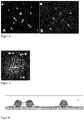
- Microparticles immobilized on the surface of a carrier are overlaid by a reaction solution. Subsequently, the reaction solution is removed so that adjacent non-contacting microparticles are no longer covered by a continuous layer of reaction solution.
- the microparticles act as nucleation points around which a liquid residue remains, which forms a spatially separated reaction space.
- the method according to the invention preferably comprises the steps of: a) applying a sample and a reaction solution to a support, the reaction solution being suitable for producing a measurable reaction product in a signal amplification reaction, depending on the presence of the analyte to be detected; b) carrying out the signal amplification reaction; c) optical measurement of the reaction products; and d) optionally providing the measurement data for the calculation of an analyte concentration in a sample, wherein a plurality of spatially separated reaction chambers is established prior to performing the signal amplification reaction on the support by microparticles on the.
- Carrier be immobilized so that the microparticles from the reaction solution are overlaid and then the reaction solution is removed so that adjacent, non-contacting immobilized microparticles are no longer covered by a continuous layer of reaction solution; characterized in that the removal of the reaction solution takes place such that the surface of the support remains covered only in a region with reaction solution which immediately surrounds a contact point between microparticle and support, while surface areas of the support which are at least 0.1 times the particle diameter are removed from a contact point between a microparticle and the carrier, are no longer covered by reaction solution.
- a scalable measuring system is made available to the user, which optionally optionally combine the advantages of the methods described in the prior art in accordance with the stated question of the user.
- the inventive method is characterized in particular by the fact that it works with standard reagents possibly in the 96-well format, almost all analyte molecules in the sample recorded multiplexable, the digital evaluation or the single molecule count allows and by standard microscope but also with a Microplate reader system can be evaluated inexpensively.
- the method according to the invention relates to a method for the in vitro detection of analytes in a sample.
- in vitro is meant any environment that is not within a living organism, e.g. a human or animal body.
- the in vitro detection method according to the invention therefore expressly does not include a method which is performed on the human or animal body.
- An analyte to be detected in a sample may be an analyte of any kind or origin.
- an analyte may be a natural analyte from an animal, plant, bacterial or similar source, or it may be of synthetic origin.
- the analyte can be an organic or inorganic analyte.
- the analyte may be a peptide, protein, enzyme, lectin, antibody, antigen, aptamer, polysaccharide, lipid, nucleic acid or the like.
- the analyte to be detected has an enzymatic activity which, on contact with the reaction solution in a signal amplification reaction, leads to a measurable reaction product.
- the enzymatic activity is particularly preferably the activity of an enzyme the class of DNA polymerases, RNA polymerases, reverse transcriptases, ligases, oxidases, reductases, transferases, peroxidases, phosphatases, proteases, peptidases, lipases, glycosidases and / or luciferases.
- the nucleic acid may be deoxyribonucleic acid (DNA) or ribonucleic acid (RNA), e.g. be microRNA.
- DNA deoxyribonucleic acid
- RNA ribonucleic acid
- primers with target specific 3'-end and with a target non-specific 5 'sequence region marker sequences can be introduced into the nucleic acids during a amplification reaction which allow selective binding to a solid phase such as e.g. preferably on fluorescence-coded microparticles allow.
- the analytes may also be non-natural nucleic acid analogs or amino acid analogs, as well as compounds containing these analogs.
- An analyte may, for example, consist of nucleotides, DNA, amino acids, peptides or a composition of these substances.
- sample refers to a composition of interest that can be used for ex vivo or in vitro testing.
- the sample is preferably a biological or medical material, that is to say material which is obtained from an organism, from constituents of an organism or from cells.
- the material before being used as a sample in the method according to the invention, may be subjected to further treatment steps, e.g. to put the material in a state in which it is particularly suitable as a sample for the inventive method.
- common methods can be used, which are known in the art.
- certain substances or classes of substances e.g. Proteins, lipids or nucleic acids are purified from the material, which can then be used as a sample in the method according to the invention.
- the sample may be material obtained from a bodily fluid or comprising a body fluid.
- Body fluid can represent any fluid of the body eg serum, blood, plasma, amniotic fluid, sweat, urine, stool, cerebrospinal fluid, cerebrospinal fluid, sperm, respiratory condensates etc. and in the form of punctates, smears or similar. be won.
- the sample may also be derived from a body tissue to be examined or comprise a body tissue. Preferably, this is a body tissue from a subject, wherein the subject may be an animal, preferably a mammal, more preferably a human. With the body tissue it can also be a sample from a plant.
- the sample may also be obtained from a cell culture suspension or cell culture supernatant or comprise a cell culture suspension or cell culture supernatant.
- the sample may be recovered from a soil or water sample or may include a soil or water sample.
- the sample comprises a mixture of different analytes.
- a sample and a reaction solution are applied to a support.
- the sample and the reaction solution can be applied either successively or simultaneously to the support.
- the sample is preferably applied to the support before the reaction solution.
- the sample is applied to the support at the same time as the reaction solution, the sample and the reaction solution, prior to application to the support, e.g. can be mixed with each other.
- reaction solution refers to a substantially liquid medium.
- the reaction solution has a substrate which is converted by enzymatic activity during the signal amplification reaction, thereby producing the measurable reaction product. Accordingly, the reaction solution is suitable for generating a measurable reaction product in a signal amplification reaction depending on the presence of the analyte.
- the substrate is reacted by the enzymatic activity of the analyte and / or the signal amplification system to produce a measurable reaction product.
- substrates can be used in the reaction solution which yield a reaction product which can be measured by its absorption (see, for example, US Pat Fig. 1 and 2 ).
- substrates include, for example, tetramethylbenzidine (TMB), orthophenylenediamine or 2,2'-azino-di- (3-ethylbenzthiazoline-6-sulfonic acid) (ABTS).
- TMB tetramethylbenzidine
- ABTS 2,2'-azino-di- (3-ethylbenzthiazoline-6-sulfonic acid
- TMB is used as substrate.
- TMB peroxidase
- TMB-POD reaction product By reaction with the peroxidase TMB becomes a blue reaction product, which is optically measurable by its absorption in the range between 600-700nm ( Gallati and Pracht, "Determination of peroxidase with H2O2 and 3,3 ', 5,5'-tetramethylbenzidine.” J. Clin. Chem. Clin. Biochem. 23, 4453-460, 1985 ).
- other absorption peaks of the same dye can also be used, for example the absorption peaks of the TMB-POD reaction product at 370 nm or 450 nm in combination with pyrene, which is excited at 340 nm and emitted at 370 nm.
- the signal amplification system has the activity of an enzyme, for example a peroxidase (POD)
- substrates can be used in the reaction solution which yield a reaction product which is optically measurable by its fluorescence.
- POD peroxidase
- substrates can be used in the reaction solution which yield a reaction product which is optically measurable by its fluorescence.
- POD peroxidase
- substrates include, for example, hydroxyphenylacetic acid (HPA), hydroxylphenylpropionic acid (HPPA) or Ampliflu Red (Sigma) or a Tyramide Signal Amplification (TSA) kit (Perkinelmer).
- HPA hydroxyphenylacetic acid
- HPPA hydroxylphenylpropionic acid
- Ampliflu Red Sigma
- TSA Tyramide Signal Amplification
- Semipermeable reaction spaces are achieved, for example, by using preferably 0.5-2% gelatin solution to stabilize the reaction spaces. For this purpose, after removal of the reaction solution, the microparticles are covered with 30-50 ° C warm gelatin solution which, after cooling, encloses the reaction spaces. Due to the semipermeable termination, nutrients but also enzyme substrates for the detection reaction can preferably diffuse into the reaction spaces when the gelatin itself is covered with these substances. Alternatively, semipermeable reaction spaces can be designed by using a semipermeable support, as known to those skilled in the art for dual chamber cell culture vessels.
- the signal amplification system detects the activity of an enzyme, e.g. a peroxidase, so it is also possible to use substrates in the reaction solution, which give a reaction product which is optically measurable by its luminescence.
- substrates include chemiluminescent substrates, e.g. Luminol or Lumigen ECL Ultra (Diarect).
- the signal amplification system has the activity of an enzyme, eg a phosphatase
- substrates in the reaction solution which give a reaction product which is optically measurable by its luminescence or fluorescence.
- substrates include chemiluminescent substrates, such as CSPD (Thermo Scientific) or fluorescent substrates such as DDAO phosphate or 4-MUP (see, eg Fig. 4 ).
- analyte to be detected in the signal amplification reaction can be amplified by an enzyme, as a substrate preferably TaqMan, Hybprobe-, Scorpion, LoopTag probes, molecular beacons or Amplifluor primer can be used, which together with appropriate primers, reaction buffers and nucleotide triphosphates be used in the reaction solution for example, a real-time PCR in the reaction space. This results in progressing amplification depending on the amount of reaction product formed a fluorescence signal.
- an enzyme as a substrate preferably TaqMan, Hybprobe-, Scorpion, LoopTag probes, molecular beacons or Amplifluor primer can be used, which together with appropriate primers, reaction buffers and nucleotide triphosphates be used in the reaction solution for example, a real-time PCR in the reaction space. This results in progressing amplification depending on the amount of reaction product formed a fluorescence signal.
- the reaction solution preferably comprises other substances besides the substrate.
- These substances may be e.g. to act dyes, preferably to fluorescent dyes.
- these fluorescent dyes are those whose excitation and / or emission are quenched by the reaction product resulting from the signal amplification reaction.
- the fluorescent dyes may also be located in the microparticles, on the microparticle surface.
- the reaction solution or microparticles or the carrier may comprise fluorescent dyes excited between 600-700 nm and emitting such as e.g. Atto 590, Atto 647N, Cy5 and their derivatives, which are quenched by the reaction product.
- the spatial separation of the reaction spaces of individual microparticles is further improved by the use of detergent-free reaction solutions.
- the carrier used in the process of the invention provides a surface on which the spatially separated reaction spaces can be established.
- the carrier can be designed as a slide, blister, microtiter plate, capillary or tube.
- the support is a planar support or a substantially planar support.
- the planar support is a cavity of a microtiter plate.
- the process of the invention may be in the form of a microarray, e.g. be performed by means of a slide or a microtiter plate.
- the carrier may be made of various materials such as metals, ceramics, glass and transparent or non-transparent plastics such as e.g. Polycarbonate, polystyrene, polypropylene, siloxane, polycarbonate.
- Preferred supports are nylon membranes, siloxane, epoxy glass and boron fluorate glass.
- the support surface may be in unmodified or modified form.
- the support surface can be functionalized by modification with functional groups.
- Preferred functional groups are e.g. Carboxy, azide, alkyne, sulfohydryl, epoxy, amino, hydroxy, sulfonic acid, pegylyl, acrylic, or phosphate groups.
- the spatial separation of the reaction spaces of individual microparticles is further improved by the use of carriers with hydrophobic surfaces.
- the supports and / or microparticles used in the method according to the invention preferably have on their surface binders which are specific for the analytes to be detected.
- binders is explained in more detail below.
- the binders to the support may be in a two-dimensional arrangement preferably by piezo printing technique, spraying or dot matrix printing in discrete, i. separated spots are printed on the surface of the carrier.
- the coupling of the binders preferably leads to an increase in the hydrophilicity in the region of the spots in comparison to the surrounding, non-printed surface of the support. These differences in hydrophilicity facilitate the formation of completely separate reaction spaces.
- the spots can have a diameter of 0.5 ⁇ m to 500 ⁇ m, preferably from 1 ⁇ m to 400 ⁇ m, more preferably from 2 ⁇ m to 200 ⁇ m, very particularly preferably from 5 ⁇ m to 50 ⁇ m.
- the carrier may also be homogeneously coated with binders. An advantage of a homogeneous coating with binders is that a particularly large amount of analyte molecules can be bound from the sample.
- Reaction space limitation spatially separated reaction spaces
- a plurality of spatially separated reaction spaces is set up on the support. This is done by first microparticles being immobilized on the support before, during or after the application of the sample and the reaction solution, so that the microparticles are covered by the reaction solution (step i).
- the sample is first applied to the carrier, then the microparticles are immobilized on the carrier and then the reaction solution is applied to the carrier.
- the microparticles are immobilized on the support and then the sample is applied to the support before the reaction solution.
- the sample with the microparticles is simultaneously applied to the carrier and the microparticles are immobilized, the sample and the microparticles being mixed together beforehand, for example, and then the reaction solution is applied to the carrier.
- the microparticles are applied to the support simultaneously with the sample and the reaction solution and immobilized there, whereby, for example, first the sample can be mixed with the reaction solution before the microparticles are added.
- the microparticles are immobilized on the support and then simultaneously applied the reaction solution in admixture with the sample on the support.
- sample is applied to the support before the reaction solution
- excess sample components may be removed from the reaction mixture prior to application of the reaction solution, e.g. to ensure the greatest possible removal of unbound or non-specifically bound analytes. This is done for example by decanting or aspiration and can be further intensified by further washing or cleaning steps.
- microparticles have been permanently immobilized on the support, removal of the excess sample components can be accomplished by centrifugation.
- a magnetic field can also be applied so as to ensure that removal of the superfluous sample constituents does not also remove the magnetic particles.
- reaction solution is removed so that adjacent, non-contacting microparticles and possibly spots are no longer covered by a coherent layer of reaction solution (step ii).
- the removal of the reaction solution can also take place in that it is displaced by other porous or non-porous preferably not fluorescence-coded microparticles such as Sepharose or nanocellulose, which reduces the diffusion between two reaction spaces of adjacent microparticles so far that no disturbing exchange of reacting constituents between these reaction spaces can take place (see, eg Fig. 5 ).
- resins which are soluble in volatile solvents can be used, which are often used in electron microscopy to screen the slides, such as polyvinylformals or polyvinyl butyrals, which are commercially available under the trade names Formvar or Vinylec, Butvar and Pioloform.
- the coating of the microparticles with the reaction solution takes place by immobilizing them on the support before, during or after the application of the sample and the reaction solution to the support.
- the coating preferably takes place in such a way that a substantially uniform wetting of all microparticles immobilized on the support takes place.
- the reaction solution is preferably left on the surface of the support for 1 second to 5 minutes, more preferably 1 second to 10 minutes, most preferably 1 second to 1 minute.
- microparticles are understood as meaning particle particles having an average diameter of less than 1 millimeter.
- the microparticles preferably have an average diameter of from 0.01 to 100 ⁇ m, more preferably from 0.05 to 50 ⁇ m, very particularly preferably from 1 to 30 ⁇ m, particularly preferably from 2 to 20 ⁇ m they are also called nanoparticles.
- the microparticles may have different shapes, e.g. they may be spherical, elliptical, cylindrical or cuboidal.
- the microparticles may be regular or irregular in shape.
- the microparticles are spherical.
- the microparticles can be triangular, circular or differently shaped discs, as they arise during the cutting of a rod with a corresponding cross-sectional area.
- microparticles used in the process according to the invention may comprise or consist of one or more materials and accordingly represent homogeneous or heterogeneous microparticles.
- the microparticles are preferably made of a polymeric material, e.g. Polystyrene, polyacrylic acid, polyacrylonitrile, polyamide, polyacrylamide, polyacrolein, polybutadiene, polycaprolactone, polycarbonate, polyester, polyethylene, polyethylene terephthalate, polydimethylsiloxane, polyisoprene, polyurethane, polyvinylacetate, polyvinylchloride, polyvinylpyridine, polyvinylbenzylchloride, polyvinyltoluene, polyvinylidenechloride, polydivinylbenzene, polymethylmethacrylate, polylactide, polyglycolide, Poly (lactide-co-glycolide), polyanhydride, polyorthoester, polysulfone, polyether
- the microparticles can consist of other polymer materials, such as. Carbohydrates such as carboxymethylcellulose or hydroxyethylcellulose, agar, gel, polypeptides, but also other materials eukaryotic and prokaryotic cells, lipids, metal, resins, latex, rubber, silicone such as polydimethyldiphenylsiloxane, glass, melamine, silica, charcoal, kaolinite, bentonite.
- the microparticles consist of melamine, silica, polysulfone, polystyrene and / or polyether, very particularly preferably polymethyl methacrylate.
- Polymers on the microparticle surface may be in unmodified or modified form. Possible functionalizations are, for example, carboxy, sulfohydryl, epoxy, amino, hydroxyl, sulfonic acid, pegylyl, acrylic or phosphate groups. The Depending on ambient conditions (eg pH, temperature), surface polymers can change their properties and thereby, for example, fluoresce or become reactive.
- the functionalization of the surface of the microparticles can also be achieved, for example, by hydrogel-like matrices, such as those formed by polyacrylic acid, poly (ethylene glycol) methacrylates (PEGMA), dextran, dextran sulfate or polyethylene glycol (PEG). Such functionalizations ensure that the specificity of the binders is not reduced and binding of nonspecific analytes is minimized.
- microparticles may be in the form of microcomposites.
- Microcomposites comprise two or more different polymer materials which may be mixed together and thus represent matrix particles having a substantially homogeneous distribution of the polymer materials over the particle cross section.
- the microcomposites may also be in the form of microcapsules having a core as inner layer and one or more further layers. For microcapsules, the various polymer materials are essentially in different layers.
- the core of microcapsules may be in solid, liquid or gaseous form (hollow spheres).
- Such polymer-based microcomposites in the form of microcapsules or matrix particles are known in the art ( Ch. A. Finchand R. Bodmeier: "Microencapsulation” in Ullmann's Encyclopedia of Industrial Chemistry, 6th Ed. 2001, electronic release ).
- the microparticles are in the form of microcapsules.
- they comprise or consist of a core as an inner layer and two further layers, namely a middle and an outer layer.
- at least the outer layer is made of a temperature resistant material, e.g. Melamine.
- the outer, the middle and the inner layer of the microparticles consist of a temperature-resistant material, so that these microparticles are suitable to be used in the method according to the invention, in which one or more steps are carried out at elevated temperatures.
- the microparticles may be porous or partially porous for the purpose of surface enlargement.
- both the supports and / or the microparticles used in the method according to the invention may preferably have binders on their surface which are specific for the analytes to be detected.
- the term "specific” or “specific binding” means that under the chosen conditions, the binder can preferably bind selectively to the analyte to be detected.
- the binders may be natural or synthetic substances.
- the binders may be based on (poly) peptides, poly or oligonucleic acids, polysaccharides, lipids or the like.
- the binder is a polypeptide such as a cell adhesion molecule from the group of integrins, cadherins, selectins or members of the immunoglobulin (Ig) superfamily.
- the polypeptide is an antibody, which may include both a polyclonal and monoclonal antibody having a classical antibody structure and derivatives or fragments derived therefrom. Such fragments are known as Fab, F (ab) 2, dsFv fragments, scFV fragments and single chain antibodies.
- the binder is an antibody.
- the binder may be a nucleic acid, e.g. DNA or RNA act.
- they are single-stranded oligonucleotides, more preferably aptamers.
- synthetic nucleic acid analogs are possible as binders.
- the binders may have modifications such as a fluorescent label.
- modifications such as a fluorescent label.
- suitable markers and methods are known with which binding molecules can be modified.
- the coupling of the binders to the microparticles can be covalent or non-covalent.
- Covalent coupling can e.g. by 1-ethyl-3- (3-dimethylaminopropyl) carbodiimide to carboxy functional groups on the surface of the microparticles.
- Non-covalent coupling can e.g. by hydrophobic or ionic interaction of the binder with the microparticles, wherein the microparticles may be surface-functionalized or not.
- the binders may also be biotinylated and thus bind to the surface with avidin-coated microparticles. It is likewise possible to bind covalently or noncovalently coupled capture oligonucleotides to the microparticle surface, to reversibly hybridize to the corresponding binders which have complementary sequence segments with the capture oligonucleotide or to which corresponding complementary oligonucleotides are bound.
- more than one microparticle population is used in the method of the invention to detect more than one analyte in a sample (multiplex detection).
- the different microparticle populations differ from one another in at least one feature.
- more than one microparticle population is used in the method of the present invention, with the various microparticle populations differing at least in that they carry binders that differ in their binding specificity.
- the different microparticle populations have binders specific for different analytes. This means that if e.g. If a microparticle population has binders with a specificity for a first protein, then another microparticle population may have any other specificity except that for the first protein.
- the microparticle populations may also differ from each other due to other features.
- the microparticles or microparticle populations are fluorescence and / or size coded so that different microparticles or microparticle populations can be distinguished from each other by their fluorescence and / or size.
- These discs but also rods can have defined holes, if the rod from which they are tillspant inside hollow channels of different shape or a constant positioning over the entire length of the rod has.
- the resulting hole patterns, specific to each rod can be used to encode different populations that are cut by different rods.
- the disks can also be produced by injection molding, for example.
- the disks can experience on one or both cross-sectional surfaces an indentation or a cap-like bending whose space contributes to the size of the reaction space.
- the discs can also be designed annular, by having a hole in the middle, which co-determines the size and arrangement of the reaction space substantially.
- the diameter of the disks is preferably 5 ⁇ m to 1 mm and particularly preferably 10 ⁇ m to 30 ⁇ m.
- the holes contained therein may have a diameter of 1 .mu.m to 0.9 mm and preferably a diameter of 1 to 25 .mu.m.
- the height of the disks is 0.5 ⁇ m to 1 mm and preferably 1 ⁇ m to 100 ⁇ m.
- Disc-shaped microparticles can be fluorescence-coded in the same way as spherical microparticles, and thus are preferably used for multiplex detection.
- the advantage of using disc-shaped microparticles is that the reaction space can easily accommodate a larger volume of reaction or sample solution, which increases the sensitivity of the tests as well as the dynamic range.
- Disk-shaped microparticles may preferably be characterized in that the disk height is greater than the disk diameter and can be 1-1000 ⁇ m, preferably 10-100 mm, so that a hollow cylinder is formed.
- the microparticles may have fluorescent, magnetic, paramagnetic and / or surface-functionalized properties.
- the microparticles may have fluorescent properties.
- the microparticles may have intrinsic fluorescence on the one hand. Self-fluorescence of the microparticles can be generated, for example, by the microparticles containing the mineral fluorite in one or more of their layers. Alternatively, or in addition to the presence of intrinsic fluorescent materials, the microparticles may still have a fluorescence coding.
- Fluorescence-coded microparticles are known to the person skilled in the art and are described, for example, in US Pat DE 699 07 630 T2 and DE 10054382 A1 described.
- the term "fluorescence coding" in the context of the present invention is understood to mean that the microparticles comprise fluorescent dyes, these fluorescent dyes being incorporated either in one or more layers of the microparticles or the fluorescent dyes being coupled directly or indirectly to the surface of the microparticles.
- Fluorescent dyes which are bound to the surface of the microparticles can thus have the function of a color coding as well as the function of the indication of binding or reaction kinetics, if, for example, their excitation and / or emission are quenched by the reaction product of the signal amplification reaction.
- Fluorescent dyes or fluorophores are all gaseous, liquid or solid inorganic and / or organic compounds which, after excitation, release the absorbed energy in the form of radiation of the same, longer or shorter wavelength.
- the fluorescent dyes can emit detectable luminescent signals or fluorescence or phosphorescence.
- fluorescent dyes which can be used are: dansyl chloride, fluorescein isothiocyanate, 7-chloro-4-nitrobenzoxadiazole, pyrene-butyrylacetic acid anhydride, N-iodoacetyl-N '- (5-sulfonic-1-naphthyl) -ethylenediamine, 1-anilinonaphthalene-8-sulfonate, 2-Toluidinonaphthalene-6-sulfonate, 7- (p -methoxybenzylamino) -4-nitrobenz-2-oxa-1,3-diazole, formycin, 2-aminopurine ribonucleoside, ethenoadenosine, benzoadenosine, ⁇ - and ⁇ -parinaric acid, ⁇ 9, 11,13,15 octaecatetraenoic acid and / or cadmium selenite crystals of one or more sizes, etc.
- transition metal complexes containing the following substances: ruthenium (II), rhenium (I) or osmium and iridium as the central atom and diimine ligands; phosphorescent propyrins with platinum, palladium, lutetium or tin as the central atom; phosphorous complexes of rare earths such as europium, dysprosium or terbium; phosphorescent crystals such as ruby, Cr-YAG, alexandrite or phosphorescent mixed oxides such as magnesium fluorogermanate or cadmium selenite crystals, fluorescein, aminofluorescein, aminomethylcoumarin, coumarin 6, rhodamine, rhodamine 6G, rhodamine B, tetramethylrhodamine, ethidium bromide, acridine orange and / or quantum dots.
- transition metal complexes containing the following substances: ruthenium (II), r
- fluorescent dyes e.g. the following substances are used in combination: ruthenium (II) - (tris-4,7-diphenyl-1,10-phenanthroline) / HPTS, ruthenium (II) - (tris-4,7-diphenyl-1,10-phenanthroline) / Fluorescein, ruthenium (II) - (tris-4,7-diphenyl-1,10-phenanthro-lin) / rhodamine B, ruthenium (II) - (tris-4,7-diphenyl-1,10-phenanthroline) / Rhodamine B-octadecyl ester, ruthenium (II) - (tris-4,7-diphenyl-1,10-phenanthroline) / hexadecyl-acridine orange, europium (III) tris-theonyl-trifluoromethylacetonate / hydroxy
- Aminocoumarin / Atto647N aminofluorescein / tetramethylrhodamine, aminofluorescein / ethidium bromide and DAPI / rhodamine.
- three fluorescent dyes for coding the microparticles, such as e.g. Aminocoumarin, rhodamine and Atto 647N, DAPI / aminocoumarin / rhodamine, aminocoumarin / rhodamine / Atto647N or aminocoumarin, fluorescein and rhodamine.
- the microparticles are in the form of microcapsules.
- they comprise or consist of a core (inner layer) and two further layers, namely a middle and an outer layer.
- the layers differ fluorescence optically.
- microparticles There is also the possibility of structure formation within the microparticles, with further fluorescent and / or fluorescence-coded microparticles being copolymerized into one or more layers of the microparticles.
- patterns can be generated in the microparticles in a targeted manner, e.g. coarse or finely granulated or the number of granules per layer that can be used for the fluorescence coding of numerous populations of microparticles.
- the different fluorescent dyes are preferably selected such that the different fluorescent dyes are substantially different Own emission spectra.
- the different fluorescent dyes have respective emission maxima which are separated by more than 10 nm, preferably more than 25 nm, particularly preferably more than 50 nm.
- the dyes can be selected to have emission bands that match commercially available filters or multiband filters, or to detect multiple fluorophores with different excitation and emission bands.
- the fluorescence measured on the surface of the microparticles is referred to as "surface fluorescence".
- Surface fluorescence arises either from fluorescent dyes incorporated in the outermost layer of microparticles or, when there are binders on the microparticle surface which are themselves fluorescently labeled, by the fluorescence of these binders.
- the surface fluorescence can also be done by fluorescence labeling of the necessary for the immobilization of the binder functionalizations.
- Such functionalizations may e.g. hydrogel-like matrices as formed by polyacrylic acid, poly (ethylene glycol) methacrylates (PEGMA) or polyethylene glycol (PEG).
- one or more dyes of the classes coumarins, rhodamines or blue-blue derivatives are polymerized into the microparticles for the microparticle coding and an Atto 647N or Cy5 derivative as surface fluorescence.
- Cy5 and fluorescent dyes of higher emission wavelengths for surface fluorescence such as e.g. Atto647N be used.
- FRET pair e.g. Fluorescein and rhodamine.
- coumarin and cyanine dyes and their derivatives etc. are available for coding.
- the coding possibilities increase enormously in that one and the same dye can be used in several layers of the microparticles in different concentrations. As a result, for each layer and between different layers of different fluorescence intensity, a multiplicity of ratio-forming possibilities that can be used for the coding / decoding of the microparticle populations results.
- the microparticles may have magnetic and / or paramagnetic properties.
- the microparticles may contain in one or more of their layers a magnet or a material which reacts to a magnet. Such microparticles are referred to herein as magnetic particles.
- the material that reacts to a magnet may have superparamagnetic, paramagnetic or ferromagnetic properties.
- the material responsive to a magnet is one Metal, preferably a metal oxide.
- the magnet or the material which reacts to the magnet within the layers of the microparticles ensures secure immobilization and / or transport of the microparticles in the reaction space during the measurement or during the test procedure.
- the microparticles may have functional groups on their surface, thereby providing the microparticles with surface-functionalized properties.
- Preferred functional groups are e.g. Carboxylates, esters, alcohols, carbamides, aldehydes, amines, sulfur oxides, mercapto groups, nitrogen oxides, epoxides, acrylates or halides.
- functional groups on the surface of the microparticles may facilitate or enhance binding of the analyte to the microparticles.
- the presence of functional groups can inhibit, facilitate or enhance the binding between the microparticles.
- the microparticles and the carrier have different surface functionalizations.
- the microparticles and carriers comprise functional groups with different properties, preferably opposite affinities with respect to the same substance or compound, e.g. on water.
- Such different surface functionalizations of the microparticles and the carrier have an advantageous effect on the limitation of the reaction spaces and cause adjacent reaction spaces to be better separated from one another.
- microparticles having hydrophilic functional groups can be immobilized on supports having hydrophobic functional groups.
- microparticle formation processes Methods of making microparticles by reactive and non-reactive microparticle formation processes are known in the art.
- reactive microparticle formation the formation of the wall or matrix occurs in parallel to a polymerization, polycondensation or polyaddition process.
- non-reactive processes film-forming polymers are used directly, which are thermodynamically brought to phase separation and microparticle formation.
- processes for the encapsulation of solid or liquid core materials for example, melamine-formaldehyde resins are used.
- melamine-formaldehyde resins are versatile and easy to use and can be applied for microparticle formation from the aqueous phase.
- the microcapsule size can be adjusted depending on the reaction conditions, eg emulsifier addition or dispersion method. Another possibility is the hydrothermal crosslinking of hydroxymethyl melamine.
- the microparticles can be immobilized on a surface of the support.
- the immobilization of the microparticles on a carrier surface simplifies the subsequent steps of the method according to the invention, in particular if they are automated and carried out using standard laboratory equipment.
- the immobilization prevents the microparticles from being inadvertently removed from the reaction mixture during subsequent process steps.
- the immobilization can be permanent or not permanent. Permanent immobilization may e.g. by covalent or non-covalent binding of the microparticles to the carrier.
- a non-permanent, ie temporary, immobilization can e.g. by centrifugation or by applying a magnetic field when magnetic particles are used.
- Disc or hollow cylindrical microparticles may be non-directional, i. be immobilized with the lateral surface or the cross-sectional area on the carrier.
- Disk or in particular hollow cylindrical microparticles can preferably be immobilized directionally directed, that the material of the cross-sectional area can bind specifically and firmly to the carrier and the lateral surface not because the specific binding properties were not present or covered or chemically altered.
- the production of different bonding properties of cross-sectional area and lateral surface can be achieved by chemically modifying or covering only the outer surfaces of the hollow bar prior to cutting the slices or hollow cylinders of hollow bars, such as e.g. by siliconization, polymer coating or vapor deposition, so that no binding of this surface to the carrier is possible.
- microfibers For cutting discs and hollow cylinders, it is possible to embed bundles of hollow rods in a cuttable medium and cut them with a microtome transversely to the fiber direction. Alternatively, it is possible to coat microfibers with a polymer and to dislodge the microfiber after cutting so that the discs and hollow cylinders remain.
- the physicochemical properties of microfiber and the cladding polymer differ by e.g. different solubility in solvents, heat stability or in acids and bases, so that the more labile microfiber can be released. It is also possible to assemble bundles of microfibers, coat them with polymer, cut them and then release the microfibers.
- the immobilization of the microparticles on a support surface takes place before, during or after the application of the sample and the reaction solution. As a result, the microparticles are covered by the reaction solution. When the reaction solution is subsequently removed, non-contacting immobilized microparticles are no longer covered by a continuous layer of reaction solution.
- the immobilization of the microparticles occurs on a surface of the support before the microparticles are contacted with the sample and the reaction solution.
- Microparticles immobilized on a support surface are covered by a reaction solution.
- the establishment of a plurality of spatially separated reaction spaces on a microparticle-filled surface of the carrier is carried out by removing the reaction solution, so that adjacent, non-contacting microparticles are no longer covered by a continuous layer of reaction solution.
- reaction solution By removing the reaction solution, preferably adjacent, non-contacting microparticles are no longer covered by a cohesive layer of reaction solution.
- the removal of the reaction solution takes place such that the surface of the support remains covered only in a region with reaction solution which directly surrounds a contact point between microparticle and support, while surface regions of the support which are at least 0.1 times the particle diameter from a contact point between a microparticle and the carrier, are no longer covered by reaction solution.
- surface areas of the support which are at least 1.0 times the particle diameter, preferably 2 times the particle diameter, more preferably ⁇ 5 times the particle diameter from a contact point between a microparticle and the support, are no longer covered by reaction solution.
- the Reaction solution can also be removed to the extent that it remains only in the gap between the particle and the bottom of the vessel and thus the reaction space can be smaller than the particle diameter.
- This region of the carrier covered with the reaction solution constitutes the so-called reaction space.
- the microparticles thus act as nucleation points around which a liquid residue remains which forms a spatially separate reaction space. By capillary forces at the interfaces between microparticles and carrier so the spatially separated reaction spaces are formed.
- the microparticles used as nucleation points for the establishment of spatially separated reaction spaces may have binders on their surface or have no binders.
- the reaction solution also remains in the microparticles, so that the reaction space is also limited by the inner surface of these particles.
- the microparticles are substantially isolated on the carrier before (see, for example Fig. 6 ), preferably with an average distance corresponding to 1 to 20 times the particle diameter, more preferably 2 to 10 times the particle diameter, most preferably 3 to 5 times the particle diameter.
- Complete separation means that there is no exchange of material between the reaction spaces, which interferes with or interferes with the respective signal amplification reaction or the respective analyte detection in other reaction spaces.
- the signal amplification reaction takes place in the spatially separated reaction space.
- a spatially separated reaction space a single microparticle, but also two or more contacting microparticles may be present.
- the removal of the reaction solution preferably takes place by means of suction, evaporation or centrifugation or, if appropriate, in combination of these method steps.
- the reaction spaces are formed by capillary forces at the interface between microparticles and carrier.
- the reaction solution is removed by centrifugation with the centrifugal forces pointing obliquely or perpendicularly away from the surface of the support on which the microparticles were permanently immobilized.
- the must acting centrifugal force be matched to the strength of the immobilization of the microparticles, so that although the reaction solution are optimally removed, but the microparticles remain on the support.
- the suction is done with a pipette.
- the removal of the reaction solution can also be achieved by evaporation. It is likewise possible, by means of a centrifugal force acting essentially perpendicular to the surface of the support, to focus the reaction spaces more strongly on the microparticles, since in this way more reaction solution can be forced to the edge of the reaction vessel and to the microparticles. Accordingly, only a small area of the carrier, which surrounds the boundary layer between the microparticle and the carrier, remains wetted with reaction solution, and with a clearly sharper delimitation than without centrifugation.
- This procedure also has the advantage that the microparticles need not be immobilized permanently or by means of the application of a magnetic field on the carrier during the removal of the reaction solution, since they are pressed by the centrifugal force against the carrier and thus not permanently immobilized.
- the concentration effect of the reaction solution near the microparticles is proportional to the centrifugal force or inclination of the support against the centrifugal force, the hydrophobicity of the support and the hydrophilicity of the microparticle surface. It is also possible to cause the centrifugal force to act away from the surface of the support on which the microparticles have been immobilized.
- centrifugal force it is possible for the centrifugal force to act alternately away from and away from the surface of the support on which the microparticles reside. As a result, excess residues of the reaction liquid which are not required for the reaction spaces, in particular from the wells of a microtest plate, are removed particularly effectively.
- the support may optionally have an opening in the surface occupied by microparticles to be removed via the centrifuged reaction solution.
- the carrier is designed in the form of a microtiter plate, then its cavities can preferably be provided with a bore or a hole in the edge region.
- the opening in the cavity bottom is preferably 0.1 to 1.0 mm.
- reaction space limitation can be used to limit various reactions to different reaction spaces in order to minimize mutual interference of the various reactions known, for example, in multiplex PCR.
- reaction space limitation can be used to statistically distribute analytes in the sense of a digital assay format to different reaction spaces.
- a stabilization of the separate reaction spaces takes place.
- This stabilization of the separated reaction spaces preferably takes place by coating the microparticles immobilized on the support with a separating liquid (see, for example, US Pat Fig. 4 ).
- the separating liquid is immiscible with the reaction solution.
- the reaction solution is an aqueous solution and the separation liquid is an oily composition.
- the reaction solution may be an oily composition and the separation liquid may be an aqueous solution.
- the oily composition is an oil, preferably a mineral oil or silicone oil.
- the oily separating liquid may also contain detergents and emulsifiers such as Triton X-100, ABIL EM 90 (Degussa), Span 80, Tween 80 in concentrations of 0.1-10% and preferably 1-5%.
- detergents and emulsifiers such as Triton X-100, ABIL EM 90 (Degussa), Span 80, Tween 80 in concentrations of 0.1-10% and preferably 1-5%.
- the stabilization of the separate reaction spaces can also be achieved by covering the liquid film of the reaction solution with a coverslip.
- microparticle population is used to stabilize the reaction spaces between the microparticles, thus using this other microparticle population as a kind of spacer or as a diffusion barrier between different reaction spaces.
- This other microparticle population may have different properties in terms of, for example, size, fluorescent, magnetic, paramagnetic and / or surface functionalized properties as compared to the microparticles used to set up the spatially separated reaction spaces.
- the spacing of the reaction spaces between the microparticles used to set up these reaction spaces can be increased or decreased to accommodate the diffusion and availability of reaction solution for the particular application to be able to adapt.
- microparticles may preferably be of Sepharose or Nano Cellulose, however also consist of glass or similar polymer materials, as have also been described for the production of fluorescence-coded microparticles. Mixtures of microparticles and nanoparticles can also be used with particular preference in order to reduce diffusion in the poultry gaps between the reaction spaces in a particularly effective manner. These other micro- or nanoparticles are preferably used for the design of the reaction spaces, for example, in their inner pore structure reactants, reaction products or sample molecules can be added and released by diffusion again.
- starting products of the signal amplification reaction such as nucleotide triphosphates
- starting products of the signal amplification reaction such as nucleotide triphosphates
- relatively high molecular weight reaction products such as amplification molecules of a PCR are too large to penetrate into the pores of the particles and thus in the reaction space remain close to the microparticles used for the establishment of the reaction spaces remain.
- low molecular weight reaction products known as PCR inhibitors can easily diffuse out of the reaction space by diffusing into the surrounding porous particles.
- the surface of the other microparticles may also be chemically activated, as in the case of bromocyano-Sepharose or by oxidation in the case of nanocellulose.
- reactants or reaction products of the signal amplification reaction can be bound to the surface of these particles before, during or after the signal amplification reaction in order to influence the signal amplification reaction.
- Such substances may preferably be analytes from the sample, analyte-like or identical standard molecules for reference purposes, enzymes, antibodies but nucleic acids or oligonucleotides.
- all oligonucleotides may be bound for a PCR and on the surface of the other particles, the analyte molecules. The binding of the analyte molecules takes place.
- the reaction spaces can be protected over long periods of time, eg over several hours or days, from environmental influences such as dehydration.
- the dehydration in particular when the signal amplification reaction requires higher temperatures, is further reduced if further microparticles with a diameter of preferably 1-100 ⁇ m are contained in the separating liquid used for coating.
- the microparticles contained in the separating liquid sink after covering the reaction space and thereby form a sediment layer. This avoids direct contact of the convection flow in the separating liquid with the reaction solution.
- reaction solution is an aqueous solution
- reaction solution it is likewise possible for the reaction solution to be protected against evaporation by water-binding substances and, accordingly, an overlay with an oily composition as separating liquid can be dispensed with.
- the reaction solution can partially or completely evaporate. Evaporation causes the reaction spaces to shrink and adjacent, confluent reaction spaces, e.g. Separate microparticles that are too close together. Complete evaporation of the reaction solution is preferably achieved by addition of 0.5-10% glycerol, 1-30% sucrose and / or by addition of 0.001-6M betaine and preferably 1-3M betaine. This process variant can also be used to selectively stop the signal amplification reaction during the drying of the reaction solution.
- the layer thickness of the reaction spaces can be adjusted by using microparticles with a defined diameter.
- the layer thickness is preferably between 10 nm and 100 ⁇ m, preferably between 50 nm and 100 ⁇ m, very particularly preferably between 1 ⁇ m and 30 ⁇ m, particularly preferably between 2 ⁇ m and 20 ⁇ m.
- the signal amplification reaction is carried out. This takes place in the spatially separated reaction spaces depending on the presence of the analyte to be detected.
- the measurable reaction product is formed by using the substrate present in the reaction solution, which is converted by an enzymatic activity.
- the amount of reaction product formed in a spatially separate reaction space can be used as a measure of the amount of analyte to be measured in this reaction space.
- the measurable signal of the reaction product is amplified.
- the longer the duration of the signal amplification reaction the more reaction product is produced and the stronger the measurable signal of the reaction product becomes.
- the signal amplification reaction preferably takes place for more than 30 seconds, more preferably for more than 5 minutes, and the time interval is very particularly preferably 5 minutes up to 48 hours. Particularly preferred is a signal amplification reaction of 1 minute to 3 hours.
- the enzymatic reaction of a substrate during the signal amplification reaction preferably comprises immunological detection.
- the immunological detection can be an ELISA (enzyme-linked immunosorbent assay).
- the support may have binders on its surface, the binders preferably being specific for the analytes to be detected.
- the microparticles used for the establishment of the separate reaction spaces have no binders on their surface which are specific for the analyte to be detected.
- PCR polymerase chain reaction
- the microparticles can be coated with streptavidin and individual, several or all probes and primers, which are eg in the reaction solution, either at the 5 'end or internally biotinylated.
- the probes and primers on the microparticles are bound via the avidin-biotin bond.
- the streptavidin denatures, so that the probes are partially or completely delivered into the reaction space.
- Release of the primers from the microparticle surface enhances hybridization kinetics with the analyte nucleic acid as a template, thus increasing the signal strengths and sensitivity of the assay system.
- the further PCR preferably takes place exclusively in the liquid phase, ie the reaction solution, which can shorten the diffusion time and thus the duration of the PCR in comparison to the solid-phase PCR in the immediate vicinity of the microparticle surface.
- the binders may preferably be constructed from repetitive nucleic acid sequences that are complementary to the analyte-specific portion of primers and probes. In particular, however, they have complementary nucleic acid sequences to analytunspezifischen sequences of primers and probes.
- primers and probes of various PCR systems are hybridized to the surface of microparticles of different microparticle populations. This makes it possible to perform different PCR systems in parallel but spatially separated in different reaction spaces.
- Such influences which can be reduced or avoided by the method according to the invention are e.g. Primer artifacts, competitive inhibition or false priming. These influences have a negative effect on the sensitivity and specificity of the various PCR reactions and thus represent important limitations of multiplex PCRs.
- the need for optimization which is required in most multiplex PCR due to the negative effects described, drastically reduced.
- probe primers on the surface of fluorescence-coded microparticles are reversibly bound via avidin-biotin or capture probes.
- Probe primers are oligonucleotides and consist of a template-specific 3 'portion with a length of preferably 10-30 nucleotides and a template-unspecific 5' portion with a length of preferably 20-30 nucleotides.
- the 5 'regions of the probe primers of an amplicon preferably differ from one another in that no cross-priming occurs within an amplicon.
- the probe primers initially allow hybridization of the 3 'end to the template and enzymatic extension complementary to the template.
- both Probe primer of a PCR amplicon are on the universal primer, in a concentration of preferably 0.05-3 ⁇ M together with the polymerase and the nucleotides, and preferably with the probes, in a probe concentration of 0.01-3 M , to be placed in the master mix, amplified.
- the universal primers preferably correspond to the sequence of the template non-specific portion of the probe primers. They enable effective amplification, even if the probe primers are contained in the reaction space in comparatively low concentration. It is also possible that universal primer and its corresponding 5 'portion of the probe primer have a sequence that results in the formation of amplicon concatamers during PCR.
- the universal primers are structured as Amplifluor- or Scorpion primer and serve for all running in the reaction mixture PCR as a universal Signaling component. Multiplexing in each reaction space is possible by using different probes, which are used with different fluorescent dyes for the detection of different dyes. It is also possible to differentiate different amplicons by virtue of their different number of base pairs being able to bind specific amounts of DNA-binding or intercalating dyes, such as SybrGreen or EvaGreen. By melting curve analysis, melting curve peaks at different melting temperatures and specific signal intensities can be assigned to the different targets using these methods.
- the sample or the microparticles immobilized on the support are contacted with a signal amplification system prior to performing the signal amplification reaction in step b).
- the signal amplification system has a first and a second element.
- the first element binds specifically to the analyte to be detected, which may preferably be bound to a binder of the microparticle or the carrier or is present unbound in the reaction solution.
- the second element has an enzymatic activity which is suitable, upon contact with a reaction solution in a signal amplification reaction, to give rise to a measurable reaction product. By incubation with the signal amplifier system, an increased amount of measurable reaction product can be achieved in the later step b) of the process according to the invention.
- contact is understood to mean a physical state of contact which is carried out under conditions which bring the contacting of the sample or the enable microparticles immobilized on the support with the signal amplification system.
- Suitable conditions for contacting the sample or immobilized microparticles with the signal amplification system are known in the art. These conditions preferably include a liquid medium and / or wetting / contacting at a temperature of> 0 ° C to ⁇ 95 ° C.
- first element preferably bind selectively to the analyte or to the binder containing the analyte under the chosen conditions.
- the first element may be based on (poly) peptides, poly or oligonucleic acids or the like.
- the first element is a polypeptide, preferably an antibody, wherein both a polyclonal and monoclonal antibody of classical antibody structure and derivatives or fragments derived therefrom may be included.
- the first element may also be a nucleic acid, preferably an oligonucleic acid, more preferably a DNA oligonucleic acid.
- the "second element” may be a substance having catalytic properties, e.g. an enzyme, DNAzymes, MNAzymes or catalytic antibodies (catmab).
- the second element is a peroxidase, in particular a horseradish peroxidase (HRP, abbreviation for English horseradish peroxidase).
- HRP horseradish peroxidase
- the analyte and / or the signal amplification system has an enzymatic activity.
- the signal amplification system has an enzymatic activity which, upon contact with the reaction solution in a signal amplification reaction, results in a measurable reaction product.
- the enzymatic activity is preferably the activity of an enzyme from the class of DNA polymerases, RNA polymerases, reverse transcriptases, ligases, oxidases, reductases, transferases, peroxidases, phosphatases, proteases, peptidases, lipases, glycosidases and / or luciferases.
- the signal amplification system may comprise as the first element a polypeptide, e.g.
- the signal amplification system may comprise as a first element a nucleic acid, e.g. include a DNA oligonucleic acid which is reacted with an enzyme, e.g. Peroxidase, labeled as a second element. It is possible that e.g. a peroxidase-avidin conjugate binds biotinylated oligonucleotides as the first element.
- Detection of the analyte using the signal amplification system can be either direct or indirect. If the proof is direct, the first and the second element are directly connected.
- the first element may be an antibody, which is associated with, for example, a peroxidase as a second element. If the evidence is indirect, the second element is not directly connected to the first element, but is located on another element. This further element may be based on (poly) peptides, poly or oligonucleic acids, microparticles or the like.
- the first element may be an antibody to which a secondary antibody specific for this antibody binds as another element. This secondary antibody may include, for example, a peroxidase as a second element.
- the further element may comprise an avidin label and a label with the second element.
- the first element may be a biotinylated antibody to which an avidin-labeled microparticle or an avidin-labeled secondary antibody binds as a further element.
- This avidin-labeled microparticle or avidin-labeled secondary antibody includes, for example, a peroxidase as a second element.
- these avidin-labeled microparticles are preferably not those microparticles used to establish the spatially separated reaction spaces.
- the first element of the signal amplification system is directly connected to the second element of the signal amplification system. The detection of the analyte preferably takes place directly with the aid of the signal amplification system.
- the signal amplification system can bind to the analyte before, during, or after it binds to its binder.
- the nature of the resulting optically measurable signal of the reaction product depends on the signal amplification system used and on the correspondingly used substrate of the reaction solution. Both suitable signal amplification systems and corresponding substrates suitable for the reaction solutions are known to the person skilled in the art.
- the enzymatic activity of the signal amplification system is the activity of an enzyme, e.g. a peroxidase, so substrates can be used in the reaction solution, which yield a reaction product which is measurable by its absorption, fluorescence or luminescence.
- an enzyme e.g. a peroxidase
- two different signal amplification systems can be used to detect two analytes in a reaction batch.
- the two resulting reaction products may have different absorption maxima which can quench two different fluorescent dyes.
- the detection of the analyte by means of a signal amplification system can be omitted if the analyte itself to be detected has an enzymatic property which, upon contact with the reaction solution in a signal amplification reaction, leads to a measurable reaction product.
- the analyte to be detected indicates the activity of an enzyme, e.g. a peptidase, so substrates can be used in the reaction solution, which yield a reaction product which is optically measurable by its fluorescence.
- substrates can be used in the reaction solution, which yield a reaction product which is optically measurable by its fluorescence.
- Peptide sequences comprising a fluorescent dye and a quencher and which can be cleaved by the peptidase. If the peptide sequence is cleaved, the spatial proximity between fluorescent dye and quencher is abolished and the fluorescent dye as the resulting reaction product can emit light after excitation with light of suitable wavelength, which can be measured.
- the detection by means of a signal amplification system can be omitted if the analyte to be detected in the signal amplification reaction can be amplified by an enzyme and in the signal amplification reaction also a substrate is used, which is converted by the activity of the enzyme to a measurable reaction product.
- This embodiment variant of the method according to the invention for the real-time polymerase chain reaction (PCR), the ligase chain reaction (LCR) or other also isothermal real-time amplification methods, such as loop-mediated isothermal amplification (LAMP), Recombinase Polymerase Amplification ( RPA), helicase-dependent amplification (HDA), beach displacment-amplification (SDA).
- LAMP loop-mediated isothermal amplification
- RPA Recombinase Polymerase Amplification
- HDA helicase-dependent amplification
- SDA beach displacment-amplification
- Heat-stable DNA polymerases such as Taq polymerase in modified or unmodified form with exonuclease activity or without exonuclease activity, are preferably used as enzymes. Also, reverse transcriptases or polymerases with strand displacement activity or RNA polymerases can be used.
- the substrate used are preferably TaqMan, Hybprobe, Scorpion, LoopTag probes, molecular beacons or Amplifluor primer, which are used together with corresponding primers, reaction buffers and Nukleotidtriphosphaten for real-time PCR in the reaction space. As the amplification progresses, a fluorescence signal is formed or quenched depending on the amount of reaction product formed.
- the optical measurement of the reaction products takes place.
- the reaction product is an optical one measurable reaction product. It is preferably a reaction product which is optically measurable by its absorption, luminescence, phosphorescence or fluorescence. The reaction product may also be optically measurable by quenching the fluorescence.
- quenching refers to processes that result in a decrease in the intensity of fluorescence of a fluorophore without destroying the fluorophore.
- the person skilled in the art knows various effects which can lead to quenching of fluorescence, such as, for example, complex formation, internal conversion, energy transfer to other molecules, which are referred to as so-called quenchers.
- Distinguishing from quenching is the decrease in fluorescence due to high excitation intensities or chemical changes of the fluorescent dye, e.g. by oxidation in the presence of oxygen. This type of fluorescence decrease is called bleaching of the fluorophore, irreversibly destroying the fluorophore.
- the quenching of a fluorophore by a quencher is reversible: as soon as the quencher is removed, fluorescence increases again.
- the optical measurement of the reaction products is preferably carried out in such a way that the spatially separated reaction spaces of the carrier are detected in a customizable manner, so that measured values can be assigned to individual reaction spaces and / or individual microparticles.
- step d) of the method according to the invention if appropriate, the provision of the measurement data for the calculation of an analyte concentration in a sample takes place.
- the measurement data of the optical measurement are preferably used for the detection and / or individualization of individual reaction spaces and / or individual microparticles.
- a mathematical algorithm is used for the recognition and / or individualization, which is preferably a ranking booster, dual octagon, inverted dual area, intensity vector algorithm or a combination thereof.
- the regions in which an analyte signal was generated, which was detected by the measurement process, are assigned to individual microparticles and / or individual reaction spaces by the respectively suitable algorithm.
- an edge-based segmentation method is preferably used, for example the well-known Canny algorithm (John Francis Canny, "Finding Edges and Lines in Images", Al Technical Reports 1964-2004, June 1, 1983). It is able to completely detect single-lying microparticles and to detect areas of closely adjacent microparticles as such.
- the Microparticles (microparticle agglomerates) already recognized as individually lying are supplied directly to the subsequent image processing steps for determining the signal intensities.
- the areas of closely spaced microparticles are separated into individual microparticles using the Ranking Booster algorithm.
- microparticles used in the process according to the invention can be present individually and / or partially close to one another on the support. If the microparticles are close to each other on the support, the ranking booster algorithm is preferably used for the virtual separation of mutually contacting microparticles.
- microparticles used in the process according to the invention are preferably spherical or circular disks.
- this algorithm for determining the analyte concentration the microparticle is lost as a single, preferably spherical structure for microparticle recognition because adjacent microparticles touch and therefore initially appear in the image as a confluent structure.
- the algorithms described below must be adapted according to the à priori applicable geometry of these objects.
- a digital image of the microparticles located on the carrier is generated, preferably created by a fully automatic recording method.
- the preferably used spherical microparticles appear in the recorded image as circular objects. Overexposure of the microparticles when creating the image should be avoided as this would limit the usability of this algorithm.
- an automatic exposure system is used which compensates for possible overexposure of the microparticles.
- the captured image is preferably first processed with a conventional object recognition algorithm that recognizes discrete microparticles and microparticle agglomerates as such (see, eg, US Pat FIGS. 9 and 10 ). Only the microparticle agglomerates are sent for further processing by the ranking booster. Preferably, the relevant image sections comprising the microparticle agglomerates can be taken up again with a higher resolution. The outer boundaries of the microparticle agglomerates are determined in this step.
- a preferably substantially circular ambient pixel mask is examined concentrically around each agglomerate pixel whose diameter corresponds to the minimum microparticle diameter.
- the relative rank of the currently examined pixel with respect to its surrounding pixel mask is determined and this value is stored at an appropriate XY coordinate in an intermediate image, the relative-rank image (see, for example, FIG Fig. 11 ).
- This relative-rank image can optionally be processed prior to further image processing with, for example, a smoothing filter, for example a 3 ⁇ 3 or 5 ⁇ 5 median filter, in order to eliminate possible local disturbances.
- the relative-rank image is preferably binarized with a threshold value, since the absolute brightnesses of the microparticles do not play any role after the ranking booster (see, for example, FIG Fig. 12 ).
- the threshold values are preferably in a range from 0.1 to 0.9, preferably from 0.25 to 0.8, particularly preferably 0.3 to 0.7, very particularly preferably 0.4 to 0.5.
- the center region of each microparticle in the resulting binary image is recognizable as a circular center slice because the center of a microparticle (in the original image) is always its brightest pixel and the pixel brightnesses fall off radially.
- the center slices preferably include an area smaller than the area of a microparticle such that the center slices of the mutually contacting microparticles do not contact each other.
- the center discs are identified.
- Other small objects in the interstices of contacting microparticles e.g. crescent-shaped or triangular are artifacts that are recognizable by their non-circular shape and too small area. These artifacts are preferably discarded without substitution and not taken into account in the further calculation.
- the center slices are enlarged step by step so that the enlarged center slices represent marks for the microparticles found.
- One layer of pixels per iteration step is added to the edge of each identified center slice (see eg Fig. 13 ).
- a point of contact between microparticles is identified (see eg Fig. 14 ).
- the detection of a contact point ends the inflation of both center disks involved, the pixels of the incomplete last layer will be removed again.
- further inflation iterations are performed.
- the center disk's inflation is limited to the original agglomeration object, ie, the iterations for a disk are stopped as soon as a pixel is added that does not belong to the initial overall object.
- the detection of the contact points between microparticles can be dispensed with and only the original agglomeration object can limit inflation, ie, incomplete layers can also be added to the center slice, but without overlapping and damaging growing center slices of adjacent microparticles ( see eg Fig. 15 ).
- the enlarged center slices mark the areas belonging to the microparticles in the image.
- the analyte concentration-dependent signal of the reaction product is determined.
- the dual-octagon algorithm described below is suitable.
- the image coordinates of an image object can not be determined precisely. This can be caused, for example, by blurring or movement of the object during the recording, such as in the case of non-permanently immobilized microparticles moving in the reaction space. Another cause may lie in the optical properties of the beam path used in the measuring system (see, eg Fig. 16 ).
- the "dual octagon" image processing algorithm disclosed in the present invention can be used. This only needs the approximate XY coordinates of the object. The method is based on the fact that there is usually a detectable background brightness in the reaction space around the object to be evaluated.
- the size of the object in pixels must be known. This information may be present by e.g. Calculation from real object size, magnification and camera resolution or available specifications of the microparticles, or obtained from additional information.
- the approximate XY coordinates of the object in the reaction space must be determinable with an accuracy of 1-10 ⁇ m. There must be a sufficient number of foreign objects in the immediate vicinity of the examined image object, so that the microparticles lie individually and the measurement fields required for the algorithm do not influence each other.
- the real number of pixels N Or associated with the object and also the XY center coordinates of the object are determined as accurately as possible. These determined coordinates are hereinafter referred to as assumed coordinates X a , Y a , since they may deviate from the unknown real coordinates X r , Y r of the object by a maximum displacement distance ⁇ D x , ⁇ D y .
- a measuring field M O for the object with a defined number of pixels N O Centered around the assumed XY coordinates of the object is a measuring field M O for the object with a defined number of pixels N O (see, for example, FIG Fig. 17 ).
- the size of this object measuring field is preferably to be dimensioned such that the object is completely contained in the measuring field even at the maximum occurring D x D y shift between real and assumed coordinates.
- the shape of the object measurement field may be circular, elliptical, a convex polygon, or any other suitable geometric shape. In particular, an octagonal polygon is suitable because this computing time can be realized in a sparing manner.
- the sum of the gray values of all pixels in the object measuring field ⁇ M O is determined.
- a second measuring field M H is defined for the background with a defined number of pixels N H.
- This background measurement field encloses the object measurement field, ie M H must contain a sufficiently large hole for M O.
- Particularly suitable is an octagonal polygon concentrically around the object measuring field M O.
- a distance may remain between the two measuring fields.
- the pixels of the background measuring field M H are subjected to outlier cleaning, ie a number of the darkest pixels and a preferably equal number of the brightest pixels are excluded from the evaluation.
- the number of pixels N H of the background measuring field is reduced to the number of pixels remaining after filtering.
- the number of pixels to discard should be based on the likelihood that foreign objects will be in the background frame.
- other suitable methods for outlier cleaning can be used, eg, methods that take into account the real distribution of gray values.
- the above formula takes into account that the object measuring field is larger than the real object and thus too many gray values of the background are included in the summation. It is assumed that the background in the area of the object's measuring field is just as high as in the surrounding background measuring field. If one multiplies the background value by the difference between the number of pixels of the object measuring field and the number of pixels of the object, one obtains the sum of the excess gray values and can subtract these from the sum of the gray values in the object measuring field. The brightness of the object GW 0 thus calculated is not even background corrected.
- the inverted dual-area algorithm is to be preferred.
- the inverted dual-area algorithm uses the central region of the microparticles for the background balance, which preferably has only a small amount of signal of the reaction product.
- the signal is typically formed as an annular structure when it arises directly on the surface of the microparticle, that is, it decreases toward the center of the microparticle. If the signal arises in the immediate vicinity of the microparticle in the liquid phase of the reaction space, then this signal remains almost completely recessed in the region of the contact surface of the microparticle with the carrier. The larger the microparticle, the more pixels available for background matching.
- the pixels are used for background matching (Area 1), whose standard deviation of the mean of the gray scale intensities of the analyte signal differ by at least a factor of 3 from the standard deviation of the mean of the gray levels of the analyte signal in the area of the outer pixel row of the microparticle (Area 2).
- the mathematical methods of the dual-octagon algorithm can easily be adapted by the skilled person to the inverted dual-area algorithm. Since the areas used for the background balance and the signal from the distribution of the signal over Depending on the particular microparticle, surfaces are preferably used that can vary in the case of multiple measurements and from microparticles to microparticles for optimizing the signal-to-noise ratio. To shorten the measuring time, it is alternatively also possible to use a priori knowledge and, for example, to use circular areas or octagons of fixed sizes for the respective microparticle population.
- a prerequisite for the application of the inverted dual-area algorithm when recording and overlaying color images of different color channels is that a chromatically corrected beam path is used for the measuring system or that the coordinate change of multicolored objects is corrected by the evaluation software taking into account the chromatic aberration.
- This requirement is preferred in multicolor fluorescence measurement systems such as e.g. in the evaluation of tests of fluorescence-coded microparticles can be applied.
- reaction spaces By limiting the reaction spaces, it is possible to reduce the analyte, which is preferably bound to the carrier, to individual analyte signals.
- the number of analytes can preferably be extrapolated directly from the reaction space volume to the sample volume.
- the reaction space volume can preferably be calculated using microparticles from the sphere geometry, since it is directly proportional to the sphere volume of the microparticles.
- the fluorescence intensity or the intensity decrease of the initial signal radially away from the center of the microparticle can be used to calculate the reaction space volume with sufficient approximation. Fluorescence intensity as well as the decrease of the fluorescence intensity during the signal amplification reaction are proportional to the volume of the respective reaction space. From the sum of the volume of all reaction chambers results in the total volume of the reaction space from which the total volume of the sample used is calculated.
- the intensity vector algorithm is to be preferred.
- the detection of the intensity vectors is carried out by concentrically detecting the signal of the reaction product of the signal amplification reaction in the reaction space by reading the pixels with a corresponding angular distance at the same radius. In a circularly concentric reaction space, the pixel intensities are the same over the entire radius with great approximation.
- the center of the concentric alignment of the intensity vectors may be a microparticle, but also an element of a signal amplification system, e.g. is indirectly bound to the carrier via an immobilized analyte molecule.
- reaction spaces partly touch one another, the mixing of reaction product of the signal amplification reaction of adjacent reaction spaces is calculated by suitable algorithms.
- Analyte-bound analytes in laterally incomplete or partially separated reaction spaces can be detected by kinetic measurement of the catalytic activity of the signal enhancement system unless the analyte is itself an enzyme detectable directly by its enzyme activity.
- the propagation of the reaction product in the reaction space by intensity vectors are described, which become larger with increasing reaction time, as long as the enzyme does not lose its enzyme activity.
- the layer thickness which is proportional to the fluorescence intensity of the reaction solution in the reaction space at the time t0, preferably for each image section determined.
- the viscosity or composition of the reaction solution and the thermoconvection depends significantly on how fast the product of the signal amplification reaction diffuses into the reaction space.
- the diffusion of the reaction product can also be greatly influenced by the use of precipitating substrates or of substrates whose reaction product binds to the carrier or to microparticles in the immediate vicinity.
- the analyte concentration calculation it is possible to determine the number of signal amplification system molecules identified, the number of signal amplified microparticles, the signal amplified reaction spaces or "black holes".
- the method of the invention it is also possible to detect the reaction product produced by the signal amplification systems as a sum signal over all the different types of reaction spaces, in particular at a higher analyte concentration in the sample. This sum signal can be calibrated to an external reference.
- the time in which the enzyme activity in the reaction spaces is quenched, as well as the extent of quenching, are proportional to the analyte concentration in the sample.
- External reference samples which have different analyte concentrations, are preferably carried along to create calibration curves in a parallel approach.
- the reaction products of the signal amplification reaction are starting from individual enzyme molecules that are dissolved or bound to the analyte may be diffusible in the reaction space or bound to microparticles or bound to the carrier, for example.
- the following method steps are preferably carried out: Formation of N equal profile vectors from the reaction center of the enzyme substrate solution in all directions at equidistant angles. There are preferably 8 vectors, preferably formed at 45 ° angle, preferably ⁇ 12 vectors. The length of the vectors L is chosen so that they fully detect even at maximum intensity of the analyte signal this until the signal level of the background is reached.
- the intensity profiles in each vector are resampled by reverse Bresenham algorithm.
- the profiles can optionally be smoothed.
- a function fitting can be performed against a suitable function, which follows the usual profile profile.
- the method can be used for positive waveforms (signal rise in the presence of the analyte) and also for inverted signal waveforms (signal drop / erase in the presence of the analyte).
- the detection of the final decay of the signal in each profile vector gives the analyte extension for that direction, whereby the expansion of the substrate reaction product can be determined.
- a step-shaped signal rise or signal drop at the beginning of the profile vector may be due, for example, to one or more solids in the reaction space, such as a microparticle to which the signal amplification system has been immobilized in the course of the detection process, and which itself preferably does not emit any signal in the signaling wavelength range.
- the extent of this stage can be used as a reference signal.
- the radial profile algorithm is preferably used.
- a radial profile is calculated.
- the mean value of all circularly arranged pixels is formed in pixel-wise growing radius intervals, which correspond to the respective radius.
- the pixels that are in the vicinity of the microparticle edge produce a distinct peak in profile profile.
- the signal results from the height of this intensity peak.
- the values at the immediate neighboring radii besides the intensity peak may be included in the signal evaluation.
- the binders specific for the analytes to be detected are on the surface of the support.
- the method according to the invention is used for the detection of an analyte in a sample (preferably single-plex detection) and comprises the steps of a) applying a sample and a reaction solution to a support which preferably bears on its surface binder if the analyte contains no enzyme wherein the reaction solution is suitable for generating a measurable reaction product in a signal amplification reaction, depending on the presence of the analyte to be detected; b) carrying out the signal amplification reaction; c) optical measurement of the reaction products; and d) optionally providing the measurement data for the calculation of an analyte concentration in a sample, and is characterized in that before performing the signal amplification reaction on the support a plurality of spatially separated reaction chambers is established by before, during or after the application of the sample and the reaction solution microparticles are immobilized on the support, so the microparticles are overcoated by the reaction solution and then the reaction solution is preferably removed by centrifugation so that adjacent non-contacting
- the microparticles act as nucleation points for the formation of spatially separated reaction spaces and preferably have no binders on their surface.
- the sample is preferably applied to the support before the reaction solution.
- the signal amplification system comprises a first element and a second element and wherein the first element binds specifically to the analyte to be detected and the second element has an enzymatic activity.
- the first element of the signal amplification system is directly connected to the second element of the signal amplification system.
- the signal amplification system has the activity of an enzyme.
- the first element of the signal amplification system is an antibody to which the enzyme, e.g. a peroxidase, bound as a second element.
- the reaction solution preferably has a substrate which, upon reaction by the enzyme, yields a reaction product which is measurable by its absorbance, preferably being TMB as substrate or which fluoresces, preferably being AmplifluRed or TSA.
- the more analyte molecules in the sample the greater the density of bound analyte molecules / detection systems on the support. This increases the likelihood that more than one analyte / detection system accounts for a reaction space.
- the intensity of the detection reaction per reaction space is preferably used to determine the number of analyte molecules per reaction space.
- the dynamic measuring range of the test system is preferably increased by increasing the number of reaction spaces per carrier, which is preferably achieved by using smaller microparticles having a preferred diameter of 1-10 ⁇ m and more preferably of 1-3 ⁇ m.
- the area of the test system in which the number of analyte molecules can be counted is placed in the cut-off range required by the application of the test. This adjustment of the cut-off is made by changing the test sensitivity preferably by changing the number of binders per area of the wearer.
- the binders which are specific for the analytes to be detected on the microparticles are located.
- the method according to the invention is used for the detection of an analyte in a sample (single-plex detection) and comprises the steps of a) applying a sample and a reaction solution to a support, the reaction solution being suitable in a signal amplification reaction as a function of the presence to produce a measurable reaction product of the analyte to be detected; b) carrying out the signal amplification reaction; c) optical measurement of the reaction products; and d) optionally providing the measurement data for the calculation of an analyte concentration in a sample, and is characterized in that before performing the signal amplification reaction on the support a plurality of spatially separated reaction chambers is established by before, during or after the application of the sample and In the reaction solution, microparticles are immobilized on the support such that the microparticles are overcoated by the reaction solution and then the reaction solution is removed so that adjacent non-contacting immobilized microparticles are no longer covered by a continuous layer of reaction solution.
- the sample is first applied to the support and then the microparticles, which have the analyte-specific binder on its surface, immobilized on the support before the reaction solution is applied to the support.
- the signal amplification system comprises a first element and a second element and wherein the first element binds specifically to the analyte to be detected and the second element has an enzymatic activity.
- the first element of the signal amplification system is directly connected to the second element of the signal amplification system.
- the signal amplification system has the activity of an enzyme.
- the first element of the signal amplification system is an antibody to which the enzyme, e.g. a peroxidase, bound as a second element.
- the reaction solution preferably has a substrate which, upon reaction by the enzyme, yields a reaction product which is measurable by its absorbance, which is preferably TMB as a substrate or which fluoresces, which is preferably AmplifluRed or TSA.
- the method according to the invention is used for the detection of an analyte in a sample (single-plex detection) and comprises the steps of a) applying a sample and a reaction solution to a support, the reaction solution being suitable in a signal amplification reaction as a function of the presence to produce a measurable reaction product of the analyte to be detected; b) carrying out the signal amplification reaction; c) optical measurement of the reaction products; and d) optionally providing the measurement data for the calculation of an analyte concentration in a sample, characterized in that prior to performing the signal amplification reaction on the support a plurality of spatially separated reaction chambers is established by before, during or after the application of the sample and the reaction solution Microparticles are immobilized on the support, so that the microparticles are covered by the reaction solution and then the reaction solution is removed, so that adjacent, non-contacting immobilized microparticles are no longer covered by a continuous layer of reaction solution.
- the analyte has an enzymatic activity, preferably the activity of an enzyme such as a peptidase, which in contact with the reaction solution in a Signal amplification reaction leads to a measurable reaction product.
- the reaction solution preferably has a substrate which, due to the enzymatic activity of the analyte, gives rise to a reaction product which can be measured by its fluorescence.
- the substrate is a peptide sequence comprising a fluorescent dye and a quencher.
- the method according to the invention is used for the detection of multiple analytes in a sample (multiplex detection) and comprises the steps of a) applying a sample and a reaction solution to a support, wherein the reaction solution is suitable in a signal amplification reaction as a function of Presence of the analyte to be detected to give rise to a measurable reaction product; b) carrying out the signal amplification reaction; c) optical measurement of the reaction products; and d) optionally providing the measurement data for the calculation of an analyte concentration in a sample, characterized in that prior to performing the signal amplification reaction on the support a plurality of spatially separated reaction chambers is established by before, during or after the application of the sample and the reaction solution different microparticle populations are immobilized on the support so that the microparticles are overcoated by the reaction solution and then the reaction solution is removed, so that adjacent, non-contacting immobilized microparticles are no longer covered by a continuous layer of reaction solution.
- microparticle populations have population-specifically different binders on their surface, which are specific for the analytes to be detected.
- the microparticle populations are fluorescence-encoded, most preferably the microparticle populations have different fluorescence coding.
- the microparticles are first immobilized on the carrier, then first the sample and then the reaction solution are applied to the carrier.
- the signal amplification system comprises a first element and a second element and wherein the first element binds specifically to the analyte to be detected and the second element has an enzymatic activity.
- the first element of the signal amplification system is directly connected to the second element of the signal amplification system.
- the signal amplification system has the activity of an enzyme.
- the first element of the signal amplification system is an antibody to which the enzyme, e.g. a peroxidase, bound as a second element.
- the reaction solution preferably has a substrate which, upon reaction by the enzyme, yields a reaction product which is measurable by its absorbance, which is preferably TMB as a substrate or which fluoresces, which is preferably AmplifluRed or TSA.
- the method according to the invention is used for the detection of multiple analytes in a sample (multiplex detection) and comprises the steps of a) applying a sample and a reaction solution to a support, wherein the reaction solution is suitable in a signal amplification reaction as a function of Presence of the analyte to be detected to give rise to a measurable reaction product; b) carrying out the signal amplification reaction; c) optical measurement of the reaction products; and d) optionally providing the measurement data for the calculation of an analyte concentration in a sample, characterized in that prior to performing the signal amplification reaction on the support a plurality of spatially separated reaction chambers is established by before, during or after the application of the sample and the reaction solution different microparticle populations are immobilized on the support so that the microparticles are overcoated by the reaction solution and then the reaction solution is removed, so that adjacent, non-contacting immobilized microparticles are no longer covered by a continuous layer of reaction solution.
- microparticle populations have population-specifically different binders on their surface, which are specific for the analytes to be detected.
- the microparticle populations are fluorescence-encoded, most preferably the microparticle populations have different fluorescence coding.
- the microparticles are first immobilized on the carrier, then first the sample and then the reaction solution are applied to the carrier.
- the signal amplification system comprises a first element and a second element and wherein the first element binds specifically to the analyte to be detected and the second element has an enzymatic activity.
- the first element of the signal amplification system is not directly connected to the second element of the signal amplification system.
- the second element is preferably connected directly to another element.
- the signal amplification system has the activity of an enzyme.
- the first element of the signal amplification system is an antibody that is biotinylated, for example.
- the further element is preferably an avidin-labeled antibody or an avidin-labeled microparticle to which the enzyme, e.g. a peroxidase, bound as a second element.
- the reaction solution preferably has a substrate which, upon reaction by the enzyme, yields a reaction product which is measurable by its absorbance, which is preferably TMB as a substrate or which fluoresces, which is preferably AmplifluRed or TSA.
- the method according to the invention is used for the detection of multiple analytes in a sample (multiplex detection) and comprises the steps of a) applying a sample and a reaction solution to a support, wherein the reaction solution is suitable in a signal amplification reaction as a function of Presence of the analyte to be detected to give rise to a measurable reaction product; b) carrying out the signal amplification reaction; c) optical measurement of the reaction products; and d) optionally providing the measurement data for the calculation of an analyte concentration in a sample, characterized in that prior to performing the signal amplification reaction on the support a plurality of spatially separated reaction chambers is established by before, during or after the application of the sample and the reaction solution different microparticle populations are immobilized on the support such that the various microparticle populations are overcoated by the reaction solution and then the reaction solution is removed so that adjacent non-contacting immobilized microparticles are no longer covered by a continuous layer of reaction solution.
- the microparticle populations are fluorescence-encoded, most preferably the microparticle populations have different fluorescence coding.
- the microparticle populations have a streptavidin coating on their surface.
- the microparticle populations additionally comprise biotinylated nucleic acid binder probes on their surface, which are complementary to the analytes to be detected.
- the microparticle populations are applied to the support simultaneously with the sample and immobilized, preferably the microparticle populations are mixed with the sample and then applied to the support. Subsequently, the Reaction solution applied to the carrier.
- the signal amplification system comprises a first element and a second element and wherein the first element binds specifically to the analyte to be detected and the second element has an enzymatic activity.
- the first element of the signal amplification system is not directly connected to the second element of the signal amplification system.
- the second element is preferably connected directly to another element.
- the signal amplification system has the activity of an enzyme.
- the first element of the signal amplification system is preferably a DNA oligonucleotide which is biotinylated, for example.
- the further element is preferably avidin, more preferably extravidin, to which the enzyme, e.g. a peroxidase, bound as a second element.
- the reaction solution preferably has a substrate which, upon reaction by the enzyme, gives rise to a reaction product which is measurable by its absorption, which is preferably luminol or Lumigen ECL Ultra (Diarect) as substrate.
- the method according to the invention is used for the detection of multiple analytes in a sample (multiplex detection) and comprises the steps of a) applying a sample and a reaction solution to a support, wherein the reaction solution is suitable in a signal amplification reaction as a function of Presence of the analyte to be detected to give rise to a measurable reaction product; b) carrying out the signal amplification reaction; c) optical measurement of the reaction products; and d) optionally providing the measurement data for the calculation of an analyte concentration in a sample, characterized in that prior to performing the signal amplification reaction on the support a plurality of spatially separated reaction chambers is established by before, during or after the application of the sample and the reaction solution Microparticles are immobilized on the support, so that the microparticles are covered by the reaction solution and then the reaction solution is removed, so that adjacent, non-contacting immobilized microparticles are no longer covered by a continuous layer of reaction solution.
- the microparticle populations are fluorescence-encoded, most preferably the microparticle populations have different fluorescence coding.
- the microparticle populations have a streptavidin coating on their surface.
- the microparticle populations additionally contain biotinylated primers on their surface, which are complementary to partial regions of the analytes to be detected.
- the sample is applied to the support simultaneously with the reaction solution and the microparticles, preferably the sample is mixed with the reaction solution and then the microparticles are added before the mixture is applied to the support and most preferably the microparticles are first applied to the support and immobilized before the support is contacted together or sequentially with the sample and the reaction solution.
- the spatially separated reaction spaces by removal of the reaction solution, e.g. By suction and centrifugation, and before carrying out the signal amplification reaction is preferably carried out a stabilization of these reaction spaces.
- the signal amplification reaction is a PCR in which the analytes are amplified.
- the reaction solution preferably has a substrate, which gives by the polymerase a reaction product which is measurable by its fluorescence.
- the substrate is a fluorescently labeled probe, e.g. a TaqMan probe.
- the present invention also relates to a kit for use in carrying out the method according to the invention.
- the kit may contain microparticles, carriers, optionally a signal amplification system, a reaction solution, optionally a separating liquid and an instruction manual for using the kit and / or for carrying out the method according to the invention.
- the microparticles may optionally have a binder on their surface.
- the kit may contain other ingredients Implementation of the method according to the invention.
- Such components may include, for example, reaction vessels, filters, solutions, and / or other means.
- the present invention relates to the use of a kit for the in vitro diagnosis of various diseases wherein the term "diagnosis” refers not only to the determination of a disease or not, but also other meanings such as the general or specific prognosis, the determination the severity of the disease, the stage of the disease or the like.
- diagnosis refers not only to the determination of a disease or not, but also other meanings such as the general or specific prognosis, the determination the severity of the disease, the stage of the disease or the like.
- the result of the method according to the invention can also be used as a basis for the optimization of the treatment, for the exclusion of certain other diseases, for decisions on further treatment options, etc.
- the method according to the invention can preferably be used for qualitative and quantitative nucleic acid amplification and detection, ultrasensitive DNA and RNA reverse hybridization assays, nucleic acid sequence screening for detection of sequence variations, ultrasensitive immunoassays, multiplex single-cell assays in miniaturized reaction spaces in vitro, each in singleplex or multiplex format.
- microparticles can be coated with any desired binders, it is possible to combine different types of binders in one assay. For example, within one assay, DNA molecules can be immobilized on one microparticle population and protein molecules on another microparticle population.
- the combination of single-molecule counting and sum signal acquisition guarantees a particularly wide measuring range, which prevents titration of samples with higher analyte concentrations.
- Sensitive fluorescence, absorption and luminescence detection can be used for the parallel determination of a wide variety of analytes using standard laboratory diagnostic reagents down to the single-molecule range.
- the method can be adapted to the most diverse detection systems.
- reaction chambers allow particularly fast tempering cycles and thus short PCR protocols.
- the incubation of the sample with the binder-coated carrier or the binder-coated microparticles is preferably carried out in a sample buffer, so that the binders specifically bind the analytes.
- the nonspecific binding of the analyte inevitably leads to a poorer lower detection limit, so that additives such as detergents or block proteins, the variation of the ionic strength of the incubation buffer and the pH of the sample buffer must be matched to the respective analyte in order to minimize unspecific binding.
- 10 ⁇ concentrated sample buffers are used.
- the incubation of the sample in wells of microtest plates preferably takes place with a substantially planar, binder-coated cavity bottom or with binder-coated microparticles immobilized on the bottom of the cavity.
- microtiter plates of polymer e.g. NucleoLink plates (Nunc) are used for nucleic acid amplification, which carry a surface coating for the covalent immobilization of biomolecules, have a sufficiently planar and transparent vessel bottom and are thermostable. Surface coatings may also be used to reduce nonspecific binding of sample molecules or detection reagents.
- a microstructuring of the carrier surface that does not affect the optical focusing is possible.
- the surfaces of the carriers can have, in addition to depressions, further structures with different properties, such as preferably hydrophilic or hydrophobic properties.
- the microarrays may be in the form of a slide or a microplate (also referred to as a microtiter plate).
- the microplate is a dished container with multiple (at least two) wells.
- Microplate-based microarrays are a multi-well microplate with the microarray biochip placed in their bottoms.
- An example of the microplate is the well-known 96-well ELISA microtiter plate.
- solid support based on self-assembling layer systems are also suitable for the implementation of the present invention.
- the application can be carried out using automatic methods.
- the binders used are preferably those which specifically bind the analyte from the sample or the reference sample with high sensitivity and specificity or which compete with the analyte for the binding of an analogue.
- synthetic affinity receptors for example, produced by molecular imprinting, can be used. Binders of one kind all have the same binding specificity for the analyte, such as monoclonal antibodies, or they differ in their or epitopic specificity. They may be specific for the same or different isoforms of the same analyte. Binder and analogue or analyte can carry fluorescent labels.
- the different binders are labeled differently (fluorescently) or one binder is, for example, labeled (fluorescently) and the other binder is unlabeled.
- the layer thickness as the extent of the reaction space perpendicular to the surface of the carrier and the homogeneity of the liquid film can be changed by changing the viscosity of the reaction solution, for example by adding 0.5-10% glycerol and or 0.01-1% Tween 20, provided thereby the signal amplification reaction is not inhibited too much.
- the homogeneity of the layer thickness of the liquid film can also be specifically influenced by the application of microparticles or different hydrophobic / hydrophilic regions on the support.
- the layer thickness of the reaction space corresponds approximately to the diameter of the microparticles.
- a lateral boundary of the reaction space perpendicular to the layer thickness is only partially caused by the microparticles themselves and reduces liquid flows in the reaction space. Nevertheless, the products of the signal amplification reaction in the reaction space spread by diffusion and currents.
- the diffusion of the reaction product can be influenced by, e.g. precipitating substrates or substrates whose reaction product has been chemically activated by the reaction and binds to the support or to microparticles.
- the analyte concentration is e.g. so high that each microparticle carries one or more analytes, then the signal of the reaction product is distributed homogeneously over the entire reaction space and depending on the detection principle increase or decrease. If the analyte concentration is low, it takes longer until the entire reaction space is filled homogeneously by the signal of the reaction product.
- the complete lateral confinement of the reaction space is immobilized by a further preferred embodiment in which the microparticles are immobilized individually on the support, with an average microparticle spacing which is preferably 4 times the diameter of the microparticles.
- the further the distance between the microparticles the more complete is the lateral separation of the reaction space of a microparticle from the reaction space of adjacent microparticles when the reaction solution is aspirated by means of a pipette.
- the liquid film falls between the microparticles and, due to the acting capillary forces, largely retreats into the gap between microparticle and carrier or upwards on the microparticle (see US Pat FIG. 3 ).
- the lateral separation of the reaction spaces of individual microparticles is improved by the use of carriers with hydrophobic surfaces and / or by the use of detergent-free reaction solutions.
- reaction spaces can also be used according to the invention as microcell culture chambers in order to preferably have the properties single or less eukaryotic or prokaryotic cells. It is possible to introduce microparticles and signal amplification systems together with the cells in a reaction space in order to examine, for example, the secretion of cytokines into the reaction space in a homogeneous assay format. If, statistically, only one cell is distributed to a reaction space, secretion performance can be measured at single cell level. It is important that the reaction solution has a composition which ensures the longest possible survival of the cells in the reaction space.
- the cells may be added as a suspension of the reaction solution, pre-adhered to the support or microparticle or cultured.
- the coating of the reaction space can be carried out by a separating liquid or by a gel, such as hydrogel or collagen gel.
- a gel may additionally be enriched with nutrients in order to ensure the longest possible survival of the cells in the reaction space.
- a dual-chamber culture system whose support is preferably microporous and which is bathed with nutrient solution for the cells from one side, preferably from the abluminal side of the cavity, so that the nutrients can diffuse through the porous support to the cells .
- Microparticles which are in the reaction spaces with the cells can be, for example, fluorescence-coded or, for example, population-specifically coated with, for example, different growth factors, extracellular matrix factors or cells, such as feeder cells or cells to be analyzed.
- Cells located on the microparticles can serve as sensors for growth factors from the sample.
- expressed fluorescent markers such as the green fluorescent protein (GFP) and derivatives thereof or FURA-2 are used as Ca 2+ markers in the cells as indicators of cellular processes, so that these processes measured using the multicolor fluorescence measuring system according to the invention can be.
- GFP green fluorescent protein
- FURA-2 FURA-2
- HRP fluorescence quenching of a fluorescent dye which is excited or emitted at a wavelength between 450-550 nm.
- the nuclease preferably cleaves an oligonucleotide which is at one end with a fluorescence quencher, such as dabcyl, and at the other end a fluorescent dye such as fluorescein has bound.
- a fluorescence quencher such as dabcyl
- a fluorescent dye such as fluorescein has bound.
- a fluorescence at a wavelength of 520 nm arises in this embodiment of the method according to the invention as a measure of the detection of the internal standard in the reaction space
- the fluorescence of a red fluorescent dye is deleted as part of the reaction solution in the reaction mixture as a measure of another analyte.
- Avidin-nuclease conjugates for binding to biotinylated detection antibodies or biotinylated capture probes are preferably used in immunoassays or in RNA hybridization assays.
- sequence-specific peptidases and the corresponding specific quencher / fluorochrome-labeled peptides or sequence-specific DNases and their labeled substrates are preferably used in immunoassays and DNA hybridization assays to generate fluorescence during the reaction.
- Devices for carrying out and measuring signal changes according to the invention before, during or after carrying out the various embodiments of the method according to the invention, which can be controlled fully automatically by computer in order to measure fluorescence, luminescence or absorption spatially resolved or imaging comprise: fully automatic control by means of computer, a positioning device for the carrier, an illumination device associated with the reaction region with which excitation light of different, defined wavelengths can be radiated, an optical device which is preferably suitable for reverse and inverse fluorescence, absorption and / or luminescence detection with corresponding optical filters or multiband filters, one or more detector device (s) such as CCD or CMOS) which generates images in response to a measured signal intensity; and an evaluation unit which generates measured values from the images.
- a positioning device for the carrier an illumination device associated with the reaction region with which excitation light of different, defined wavelengths can be radiated
- an optical device which is preferably suitable for reverse and inverse fluorescence, absorption and / or luminescence detection with corresponding optical filters or multiband filters,
- the devices may additionally comprise immobilization devices for eg magnetic or paramagnetic microparticles.
- the devices may optionally include a thermal cycler that receives the planar support and performs real-time PCR or isothermal Amplification with simultaneous reverse or inverse fluorescence optical analysis of the carrier allow.
- the thermal cycler preferably comprises 1-384 and more preferably 8-96 custom-fit pitches for reaction vessels.
- the area of the inner surface of the bottom of the reaction vessels in which the reaction chambers are located during the tempering process and preferably during isothermal phases of PCR cycles such as at the end the annealing phase or isothermal phases of melting curve analyzes can record measured values by imaging or non-imaging.
- the device can be supplemented with pumping and pipetting devices that can be used to automatically supply or remove substrates, sample material or other reaction components.
- thermocyclic heating of the reaction spaces by the radiation energy preferably a high-power LED or a diode laser, preferably in the red or ultra-red wavelength range, without the exclusion of possible other wavelength ranges emitted, preferably without, however, the material of the carrier to warm up.
- the irradiation can be reversed or preferably inverse via the lens of the evaluation unit.
- the carrier and optionally the separating liquid is preferably kept isothermally in the range or below the required reaction or hybridization temperature of preferably 45 ° C-70 ° C by, for example, pelleting elements, an air stream or a liquid stream.
- the illumination is selected so that only the reaction solution absorbs the radiation and neither the carrier nor the separating liquid optionally used to limit the reaction space.
- the energy input necessary for the heating of the small reaction spaces also remains very small, which minimizes the required cooling by heat radiation or conduction through the wall of the reaction vessel or, for example, by convection in the case of coating the reaction spaces with a separating liquid.
- the wavelength of the illumination which is already required for the measurement of the reaction spaces, for example 640 nm if Cy5 is used as a marker for the analyte fluorescence.
- a wavelength for heating the reaction solution which is greater than that of the analyte fluorescence and is irradiated evers or inversely by the inverse microscope optics or externally by the microscope optics.
- the light pulse duration for heating the reaction spaces can determined empirically or by thermography and used for all subsequent reactions. But it is also possible to give a temperature sensor molecule or more temperature sensors specific for different temperatures in the reaction solution, which emits a fluorescence signal when reaching a certain temperature.
- a DNA hairpin or a Moleular Beacon which hybridizes flush with the 3 'end to its own 5' end and carries a quencher at one end and a fluorophore at the other end, their absorption or excitation spectrum on the lighting is tuned.
- quencher or nanoparticles into the reaction solution which absorb the electromagnetic radiation in the corresponding wavelength range and convert the energy into heat.
- optically transparent vessel bottoms as carrier and / or carrier covers with low intrinsic fluorescence, which enable the fluorescence optical evaluation during the thermocyclic or isothermal carrying out the detection reaction, measurements with incident light and transmitted light fluorescence / - luminescence or absorption are possible.
- incident light fluorescence commercial microtiter plates can be used such. NucleoLink or NucleoSorb but also e.g. Commercially available flat bottom micro test plates, single cavities or 8 cavity modules (F8 bars).
- the commercially available reaction vessels used can be coated to reduce intrinsic fluorescence or be white to measure luminescence.
- the use of non-permanently immobilized microparticles requires measurement of all microparticle fluorescences during the acquisition of further measurement points, particularly high demands are placed on the speed of the hardware, such as the use of the lowest possible resolution of the objectives at high light intensity, the use of multiband filters to avoid filter changes in combination with a multi-color LED lighting, the use of an electron-amplifying camera, parallelization of the detector units.
- LEDs with emissions in the range of 350nm, 480nm, 530nm and 640nm are used and are preferably combined with the matching four-color multiband excitation / emission filters used.
- the extension of the color spectrum into the red or ultra-red range can be used especially for the temperature control of the reaction spaces.
- Detector units may preferably be arranged in rows of eight in the sense of a parallelization or may be bundled onto a camera by means of fiberglass or liquid conductors. It is also possible to measure multiple cavities simultaneously using wide-angle lenses. By Pixelbinning can be also reduce the measurement time, as the sensitivity increases, which shortens the exposure and reduces the amount of data.
- the optics are preferably designed such that the system has a pixel resolution of 0.5-2.5 ⁇ m. If the microparticles have a diameter of 1-5 ⁇ m, then preferably a pixel resolution of the optics in the range between 0.1-1 ⁇ m is used, as well as in the recording of "black holes" for the purpose of single-molecule counting.
- a preferred way of receiving the signals when microparticles are used in multilayer arrangement is the use of confocal optics.
- confocal optics With the aid of confocal optics, several levels of the multilayer can be recorded step by step in order to capture as many signaling microparticles in different planes of sharpness.
- a step size of 1-10 ⁇ m is selected between two recordings.
- the measurement not spatially resolved imaging
- conventional absorption, luminescence, fluorescence readers or scanners can preferably be used. It must be ensured that the optical focus of these devices is set to the reaction space or the reaction spaces, since due to the small layer thicknesses of the limited reaction spaces, the intensities of the measurement signals can be comparatively low. Small measurement signals can preferably be compensated by using very sensitive photodiodes or photomultipliers or by increasing the concentration of the fluorescent dye to be quenched in the reaction space.
- reaction space it is also possible to increase the layer thickness of the reaction space to one to several millimeters, in particular if in this embodiment preferably converted by peroxidase TMB to a blue reaction product and thereby a fluorescent dye with excitation and emission in the wavelength range between 600 to 700 nm in the reaction solution or on the surface of microparticles or inside of microparticles is highly sensitive deleted.
- the preferably laterally non-subdivided reaction space is in this case preferably the complete cavity of a microtest plate.
- the invention provides that in the course of the signal amplification reaction or at least after completion of the reaction, a measurement point is recorded in order to be able to calculate how much the reaction for the individual analyte was or in which concentration the analyte is present in the sample. If output signals are already measurable before the measurement, which fluctuate greatly between different reaction spaces or within a reaction space, it is possible to record a first measurement point before or at the beginning of the reaction and to use the measured values derived therefrom as the zero point or reference. This method is particularly useful when using microparticles that have a surface fluorescence that can vary between 1-50% between the different microparticles.
- the so-called outliers can be excluded from the evaluation. Thereafter, e.g. a ratio is calculated from the measured value before the reaction and at least one subsequent measured value or all further measured values in the course of or after the reaction, or the initial value is subtracted from the measured value.
- the recording and calculation of several measured values of the same reaction space enables the display of a series of measurements for the analysis of the reaction kinetics.
- the measured values can arise due to signal changes or an increase or decrease or extinction of the signal of the reaction product in the reaction space.
- the signal change to be measured may preferably include an increase in surface fluorescence on microparticles and supports, for example, when a signal amplification reaction degrades a quencher probe in the reaction solution that is complementary to a capture probe immobilized on the support carrying the fluorescence-causing fluorescent dye.
- the signal change may include a decrease in surface fluorescence on microparticles and carriers, eg, when a signal enhancement reaction forms a soluble or precipitating reaction product, eg, a dye, that quenches the surface fluorescence.
- the signal change may include an increase in fluorescence in the particular reaction space, eg when a signal amplification system converts a nonfluorescent dye to a fluorescent dye or, for example, a TaqMan probe is hydrolyzed, thereby canceling the quenching of the fluorescent dye bound to the probe.
- the signal change may preferably comprise a decrease in the fluorescence in the respective reaction space, for example by the formation of a color reaction product of colorless substrate solution, such as TMB, which is in the range of Excitation and / or emission of the fluorescent dye absorbed.
- the signal change may include an increase in the luminescence in the respective reaction space, for example in that a signal amplification reaction forms a luminescent reaction product in the reaction space.
- the signal change may comprise an increase in the intensity and spatial propagation of the absorption in the regions of the fluorescent reaction space, preferably without or without complete lateral confinement, in which individual molecules of one or more signal amplification systems are bound to the support and form a colored reaction product.
- This reaction product absorbs in the region of the excitation and emission wavelength of the fluorescent dye and the fluorescence in the reaction space is thus effectively quenched.
- dark spots in the predominantly homogeneously distributed over the entire reaction space fluorescence. That is to say so-called "black holes” result from the fact that the dye formed diffuses from the signal amplification system in all directions into the reaction space.
- the recording of measurement series is particularly suitable for detecting "black holes".
- the parameters intensity of fluorescence quenching and spatial propagation of fluorescence quenching by diffusion are preferably detected concentrically from the location of the localization of the enzyme molecule into the reaction space.
- the spread of the deletion depends on the diffusion of the reaction products but also on the flows of the reaction solution, in particular in laterally unlimited reaction spaces in the reaction space.
- the a priori concentric diffusion e.g. is approximately elliptically deformed, so that a correction calculation is required to return to the concentric model, or from the calculated area directly the intensity of the enzyme reactivity is calculated.
- the intensity distribution of the enzyme activity over time is analyzed, e.g. To decide whether the enzyme activity is attributable to one or more adjacent immobilized enzyme molecules. Since the number of immobilized enzyme molecules is proportional to the number of analyte molecules in the sample, this data analysis can increase the accuracy of the measurement. If the reaction spaces are recorded spatially by the recording of Z stacks, the "black holes" can also be recorded three-dimensionally and thus their volume used for further calculations.
- the accuracy of the measurement depends directly on the pixel resolution of the measuring system used. For this embodiment variant, a pixel resolution of ⁇ 0.5 ⁇ m used. Thus, "black holes" with a lateral diameter of 2-3 microns with a layer thickness of the reaction chambers of 2 microns can be detected safely.
- the distance between two enzymes or signal amplification systems on the carrier should preferably not fall below an average of 10 ⁇ m.
- the cavity of a 6 mm diameter microplate has the capacity of about 30 million enzyme molecules. As the enzyme density on the support increases, so will the number of closely spaced molecules that can no longer be separated optically.
- the detection of the signal intensity, the signal propagation in the reaction space for the respective "black hole” or the kinetics of both parameters are preferably used for the evaluation of a "black hole", whether it was caused by one or more enzymes.
- a fluorescence or luminescence substrate is used.
- the intensity of the signal amplification reaction and diffusion of the reaction product are to be adapted for the respective application such that a measurement takes place after 10-20 minutes in the plateau of the signal amplification reaction or several times after 0.1-20 minutes.
- Parameters for adjusting the signal amplification reaction are e.g. the change in temperature or the addition of glycerol to the reaction solution.
- the carrier may require the capture of several to many images at a pixel resolution of ⁇ 0.5 ⁇ m.
- the enzyme molecules bound to the analyte statistically disperse evenly across the support, the number of exposures can be reduced, preferably measuring at least ten times more molecules than the average non-specific binding. If the number of detected molecules is lower, a larger number of images will automatically be captured. This procedure makes it possible to effectively optimize the measuring time.
- a luminous reaction product may be formed, e.g. Ampliflu Red is used as the enzyme substrate (Sigma-Aldrich).
- Ampliflu Red is used as the enzyme substrate (Sigma-Aldrich).
- the intensity distribution of the enzyme activity of peroxidase is detected as fluorescence and not as deletion as in the "black holes” and charged.
- the method can be applied to luminescence detection.
- the required for the evaluation x / y position of a necessary number of identified microparticles per population is stored in order to find the measurement sites for recording the surface or analyte fluorescence in the detection of other measurement points.
- the surface or analyte fluorescence is detected as a reference for the surface or ligand signal recorded in the following measuring points and optionally also used for decoding the microparticle population. It is also possible to detect analyte luminescence instead of analyte fluorescence.
- the reaction product may be distributed throughout the reaction space or may precipitate or covalently bind to the surface of the support or microparticle.
- the recording of the further measuring points can take place at regular intervals before, during and after the reaction or else after a certain temperature or a specific section of a thermal cycle has been reached.
- the measurements occur during an isothermal portion of the reaction, e.g. a PCR is performed to minimize the effects of temperature variations, such as material expansion and increased convection in the reaction mixture.
- microparticle fluorescence it may be advantageous to record microparticle fluorescence during the reaction from time to time in addition to recording the surface or ligand fluorescence, since with decreasing surface fluorescence there is a risk that a microparticle will not be correctly recovered.
- an adjustment of the illuminance to the surface fluorescence can preferably be carried out when using LED, in particular when recording further measuring points. If necessary, the varied illuminance should be referenced.
- microparticles having standardized fluorescence properties can be preferably used. Bleaching is reduced by limiting the illumination to the time of image acquisition. In addition, decreasing the lens magnification allows a larger measurement area to be imaged, reducing the need for images per well.
- the avoidance of refocusing and reexposure by algorithms such as "extended-depth-of-field” (increasing the depth of field by combining several images in the Z-direction) and "high-dynamic-range” (increasing the exposure dynamics by combining a very bright and a very dark image) also shorten the measuring time and increase the precision of the measurement and improve the dynamic range of the measured value.
- fluorescent microparticles on the surface of the support can be used as a focusing aid.
- 1-10000 fluorescence-coded microparticles of a population are detected, preferably 1-100 microparticles, particularly preferably 1-10 microparticles.
- microparticle populations preference is given to using the fluorescences of the dyes incorporated in the microparticles as a whole or in the various layers. From the various e.g. Fluorescence intensities are calculated ratios (Ratios, PopID) that allow for each microparticle population a unique labeling. As a secondary distinguishing feature, different size classes, shapes and patterns of microparticles can be used.
- the fluorescence intensity of a certain emission wavelength, recognizable in the microparticle periphery as ring fluorescence can be determined before the start of a nuclease reaction for determining the microparticle population but also for determining the maximum signal of the surface fluorescence of the respective microparticle before the reaction. In the course of the reaction, this maximum signal decreases because the biomolecules are enzymatically degraded and thus the dye is released from the microparticle surface into the reaction space. For the decoding of the microparticle populations, the dye is then no longer available. Since the microparticle has been permanently immobilized, the decoding does not need to be done anymore.
- the fluorescence of the dyes incorporated in the microparticles themselves is sufficient.
- Encoding, surface and / or ligand fluorescence can also be used to reference microparticles of different sizes with respect to detected fluorescence intensities. This is preferably used to minimize errors that may result from size variations of the microparticles within a population, since the intensities of the microparticle fluorescences and the surface fluorescence vary proportionally with the diameter of the microparticles.
- the different microparticle fluorescences are also used to differentiate microparticle populations that have the same PopID but differ in diameter by preferably 2-50 ⁇ m. Particularly preferred such microparticle population differ by 3-15 ⁇ m in the middle microparticle diameter.
- preferably fluorescent or fluorescence-coded microparticles are in some cases located in a reaction space (see Fig. 9 ).
- preferably different fluorescence codes can be used in order to provide multiplexing tests via microparticle population-specific binder. It is also it is possible that there is only one population in the reaction space in order to have sufficient measurement points available for digital test systems.
- the microparticle is lost as a priori spherical structure for microparticle recognition because adjacent microparticles touch and therefore appear as a confluent structure.
- Microparticles preferably have a nearly perfect spherical shape, ie they are represented in the recorded image as circular objects. Their minimum and maximum diameters (in pixels in the picture) are known a priori (+/- 25%).
- the brightnesses of the microparticles with one another preferably vary to about 1:20, their diameter in the ratio 1: 3. Overexposure of the microparticles should not occur and is therefore compensated by automatic exposure.
- the microparticles are stochastically distributed to densely packed preferably lying in one plane.
- the image is preferably first processed with a conventional object recognition algorithm that physically recognizes discrete microparticles and agglomerates as such (see Fig. 10 ). Only the agglomerates are sent for further processing by the Ranking Booster. Preferably, the relevant image sections can be recorded again with a higher resolution. The external borders of the agglomerates are already determined here.
- a preferably nearly circular ambient pixel mask is examined concentrically around each agglomerate pixel whose diameter corresponds to the a priori known minimum microparticle diameter.
- the relative rank of the currently examined pixel with respect to its surrounding pixel mask is determined and this value is stored at a corresponding XY coordinate in an intermediate image, the relative-rank image (see FIG Fig. 11 ).
- This relative-rank image can optionally be processed before further image processing with a smoothing filter (eg 3x3 or 5x5 median filter) to eliminate small local disturbances.
- the relative-rank image is preferably binarized with a fixed threshold (eg threshold 0.5), since the absolute brightness of the microparticles after the ranking booster no longer play a role (see Fig. 12 ).
- a fixed threshold eg threshold 0.5
- the center region of each microparticle is discernible as a discrete circular slice because the center of a microparticle (in the original image) is always its brightest pixel and the pixel brightnesses fall off radially.
- the disks preferably contain only about half the area of a microparticle and therefore can not touch one another.
- the center slices are enlarged step by step.
- One layer of pixels per iteration step is added around the edge of each identified center slice (see Fig. 13 ).
- a point of contact between microparticles is identified (see Fig. 14 ).
- the detection of a contact point stops the inflation of both center disks involved, the pixels of the incomplete last layer are removed again.
- further inflation iterations are performed.
- the center disk's inflation is limited to the original agglomeration object, ie, the iterations for a disk are stopped as soon as a pixel is added that does not belong to the overall output object.
- Kinetics of formation of the reaction product of a signal amplification reaction in the reaction spaces to describe the analyte concentration and the analyte properties, respectively, are preferred for e.g. Applications recorded for real-time PCR or to determine the enzymatic activity of analytes.
- the analysis of the change in fluorescence as a result of the reaction from measurement point to measurement point yields reaction kinetics from which concentrations of the analytes or else binding constants can be calculated. If the evaluation is based on a reaction cycle, e.g. In the polymerase chain reaction, the indication of the breakthrough cycle at which the signal or signal change breaks the background is critical as a measure of the amount of reaction product formed. In this way, a more accurate quantification of the PCR products in a sample is possible than by the determination of the fluorescence intensity. By combining with melting curve analysis, it is possible to obtain further information about the sequence and hybridization properties of nucleic acid analytes.
- measurement errors are significantly reduced since the possible referencing preferably influences a microparticle population as a positive control or an external reference sample how different illumination or microparticle size can be minimized.
- the method stipulates that the influence of disturbances must be systematically recorded in order to be able to take these into account when calculating the measured values.
- disturbances may be the fading (bleaching / fading) of some fluorescent dyes as well as influences of temperature fluctuations on the measurement or the nonspecific background fluorescence.
- Example 1 represents a variant which is simple to carry out, preferably for single-plex immunoassays, in which the antigen PSA is sensitively detected (10 -13 -10 -14 M).
- Step 1 Microtest plate is coated with antibodies as a binder
- PBS-T phosphate buffer
- HSA human serum albumin
- Step 2 Incubation of the sample and binding of the analyte to the antibody
- the patient serum is diluted 1: 2 in PBS-T-HSA and 50 ⁇ l of this dilution of each sample is pipetted into a well coated with the antibody and incubated for 2 hours.
- the unbound sample components are removed from the wells by washing several times in PBS-T.
- Step 4 Incubation with the signal amplification system
- An HRP conjugate of the above-mentioned IgG fraction of an anti-prostate-specific polyclonal antibody is diluted in PBS-T-HSA 0.1 ⁇ g / ml and 50 ⁇ l are pipetted into the wells of the microtest plate and incubated for 2 hours, thus allowing the sample to escape bound PSA has been labeled with HRP as a signal amplification system.
- the unbound detection reagent signal amplification system is removed from the wells by washing several times in PBS-T.
- Step 6 Addition / partial aspiration of the TMB / Fluorocrome enzyme substrate including focusing microparticles
- a commercial TMB ready-to-use substrate solution is pipetted into the wells with addition of 100ng Cy5 / ml 0.05% Tween 20 and approximately 5000 PMMA fluorescent microparticles (excitation 480nm / emission 520nm) with a diameter of 2 ⁇ m and after 30 seconds again largely sucked off.
- planar support is covered by pipetting 50 ⁇ l of mineral oil into the cavities so that the reaction space covers the entire cavity bottom with a layer thickness ⁇ 10 ⁇ m.
- Step 8 Measurement in the F1100 Fluorescence Imager
- the microtest plate is evaluated in the Fl100 fluorescence imager (attomol) by recording fluorescence images at 520 nm with an excitation wavelength of 640 nm and an emission wavelength of 660 nm with the optical focus in the reaction space and a pixel resolution of 0.65 ⁇ m every 15 seconds. From a Z-stack, the brightest image is selected and automatically fed to the imaging process, after the quality of the images is automatically checked and, if necessary, corrected.
- Fl100 fluorescence imager attomol
- regions of lower fluorescence which deviate more than 3 times the standard deviation from the original fluorescence or the ambient fluorescence are selected and their variation over several images by intensity vector algorithms calculated and evaluated, like many molecules of the signal amplification system are in the reaction mixture. If too many signal amplification molecules are immobilized in the reaction mixture in very tightly packed form, since the analyte concentration in the sample is very high, the sample is output as positive without concentration information for the analyte.
- a quantification of the analyte is alternatively achieved via the kinetics of fluorescence quenching, ie via the reduction of the sum signal over the entire measuring space, in comparison to a reference sample. The corresponding concentration information is automatically output by the software.
- Example 2 differs from Example 1 in that by using nanoparticles floating freely in the sample as carrier of the antibodies as binder, larger sample volumes can be used, thereby increasing the likelihood that at very low concentrations of the analyte in the space to be sampled (eg patient serum or tap water) at all analyte molecules are detected during sampling.
- the analyte in the space to be sampled eg patient serum or tap water
- polymethacrylate paramagnetic nanoparticles with polyacrylic acid COOH surface coating (PolyAn) and a diameter of 200 nm are incubated after EDC activation with 1 mg of anti-troponin antibody / ml PBS for 2 h and thus coated. Unbound antibodies are completely removed by washing several times in an excess of PBS-T.
- 250 ⁇ l sample are mixed with 25 ⁇ l 0.5M PBS with the addition of 1% Tween 20 and gently mixed homogeneously.
- the already prepared wells of a polystyrene microplate were blocked with PBS-T and then filled with the prepared sample solution. All filled cavities are then mixed with 10 ⁇ l of a suspension with a defined number of nanoparticles, so that this results in complete sedimentation a layer thickness of about 10-20 ⁇ m, ie about 5x10 10 nanoparticles per cavity with about 6mm diameter.
- the sample solution mixed with nanoparticles is incubated with intensive shaking for 2 h.
- a commercial TMB ready-to-use substrate solution is pipetted into the wells with the addition of 100ng Cy5 / ml 0.05% Tween 20 and the nanoparticles resuspended therein. After about 30 seconds, the nanoparticles are uniformly sedimented magnetically, and the substrate solution is pipetted off. Only after the coating of the nanoparticle layer in all cavities with 50 ⁇ l of mineral oil is the magnet removed for the immobilization of the nanoparticles. In the approach are about 500 fluorescent micro-particles with a diameter of 10 microns for focusing. When using a suitable hardware autofocus, the addition of the fluorescent microparticles as an orientation for focusing can be omitted.
- Step 8 Measurement in the FI100 Fluorescence Imager
- the microtest plate is evaluated in the Fl100 fluorescence imager (Attomol) by recording fluorescence images at an excitation wavelength of 640 nm and an emission wavelength of 660 nm with the optical focus in the reaction space and a pixel resolution of 0.65 ⁇ m every 15 seconds. From a Z-stack, the brightest image is selected and automatically fed to the imaging process, after the quality of the images is automatically checked and, if necessary, corrected.
- Quantitation of the analyte will alternatively be via the kinetics of fluorescence quenching, ie via the reduction of the sum signal over the entire measuring space, compared to a reference sample achieved.
- the corresponding concentration information is automatically output by the software.
- polylsin-coated microparticle population is incubated in the same manner with 1 mg dsDNA / ml PBS from herring sperm and washed.
- a polystyrene microplate is incubated with 10 ⁇ g polylysine / ml PBS overnight and then washed several times with PBS. Thereafter, a suspension with 5,000 fluorescence-coded, coated microparticles of each population is pipetted one after the other or as a mixture of all three populations into the wells of the microtest plate and sedimented completely and uniformly by centrifugation or settling.
- the supernatant is aspirated and the sample, 1:50 diluted in PBS-T patient serum, pipetted into the wells and incubated for 1h, so that optionally contained in serum, specific for any of the three antigens antibodies can bind to the respective microparticle population. It is also possible to titrate the sample through several dilution steps in different wells to get into the single molecule region on the carrier bound analytes for each of the three analytes for a more accurate quantification.
- the well is incubated with anti-human IgG POD diluted as detection reagent in PBS-T for 1 h with shaking.
- a commercial TMB ready-substrate solution is pipetted into the wells with the addition of 100ng Cy5 / ml 0.05% Tween 20 and removed after about 30 seconds from the cavity by suction and immediately covered with 50 .mu.l mineral oil.
- the microtest plate is evaluated in the Fl100 fluorescence imager (attomol) by recording fluorescence images at an excitation wavelength of 480nm, 530nm and 640nm and corresponding emission wavelengths of 520nm, 560nm and 660nm with the optical focus in the reaction space and a pixel resolution of 0.65 ⁇ m every 15sec.
- the automatically optimally focused and exposed image is automatically selected and delivered to the imaging process using FastFluoscan software (Attomol), after the quality of the images is automatically checked and, if necessary, corrected.
- Step 10 Imaging and Evaluation
- the FastFluoscan software recognizes all microparticles in the image and, after evaluating the coding fluorescence of the microparticles (emissions at 520 nm or 560 nm), assigns them to one of the three microparticle populations. Thereafter, the analyte concentration-dependent Cy5 fluorescence change for the individual microparticles in the respective reaction space is determined and the kinetics of the percentage Cy5 extinction calculated. It is calculated which microparticles of a population are positive, especially if they are more closely adjacent to microparticles of other populations or the same population in the cavity, so that their reaction spaces could not be completely separated.
- the measure of this is the time that a corresponding microparticle has an erased Cy5 fluorescence relative to the average time for that microparticle population. If the deletion is significantly less than the average time, and a neighboring population shows a quenched Cy5 fluorescence, this population is considered to be negative. If it corresponds to the average time, it is considered positive. Thereafter, the positive microparticles and the negative microparticles of a population are counted and their ratio, as a measure of the analyte concentration, related to a reference sample series with calibration function to indicate the analyte concentration in the sample.
- the well is incubated with biotinylated anti-human IgG diluted as a detection reagent in PBS-T for 1 h with shaking.
- the well is incubated with streptavidin and peroxidase labeled nano / microparticles diluted as detection reagent in PBS-T for 1 h with shaking.
- RNA molecules of about 15-30 nucleotides in length are directly involved in the regulation of gene expression.
- miRNA miRNA
- the determination of miRNA concentrations in serum of patients is considered to be a less invasive procedure of high clinical relevance.
- the gold standard for the quantitative determination of miRNA in serum is real-time PCR. PCR bias, i.
- the falsification of the quantitative relations between different PCR by different PCR efficiency, or the lack of multiplexability of the PCR or too low sensitivity of hybridization methods are important limitations of the current state of the art.
- the detection of miRNA molecules is achieved due to the high sensitivity without PCR amplification.
- the use of chemiluminescence as a detection method guarantees a very high measuring range over 4-5 log steps:
- Suspensions of three differently fluorescence-coded, polyacrylic acid-bearing, COOH-modified polymethacrylate microparticle suspensions whose microparticles have a diameter of 10 .mu.m are EDC-activated and then incubated with 1 mg streptavidin per ml PBS for 2 h and thus coated with streptavidin. Unbound streptavidin is completely removed by washing several times in an excess of PBS-T. For this, the microparticles are sedimented by centrifugation before the wash solution is removed and replaced with new wash solution.
- additional microparticle populations for additional miRNAs or controls may be included in the approach.
- the streptavidin-coated microparticle populations are incubated with 100nM biotinylated miRNA probe as a binder, i. in each case biotinylated DNA oligonucleotides complementary to the miRNA miR16, anti-sense to miR16 and double-mutated to miR16 were incubated and washed specifically for the population.
- biotinylated DNA oligonucleotides complementary to the miRNA miR16, anti-sense to miR16 and double-mutated to miR16 were incubated and washed specifically for the population.
- the analysis can be extended to additional miRNA in a multiplexed approach.
- a polystyrene microplate is incubated with 10 ⁇ g polylysine / ml PBS overnight and then washed several times with PBS-T.
- RNA is isolated from human serum samples ( Li, Y and Kowdley, KV [2012] Method for microRNA isolation from clinical serum samples. Anal Biochem 431 [1]: 69-75 ) and at the 3'-end enzymatically synthesized a poly-A extension ( Shingara J, Keiger K, Shelton J, Laosing Chai-Wolf W, Owers P, Conrad R, Brown D, Laborer E [2005] An optimized isolation and labeling platform for accurate microRNA expression profiling. RNA, 11: 1461-1470 ).
- the microtest plate well is incubated with Extravidin-POD (Sigma) diluted as detection reagent in PBS-T for 1 h without shaking.
- Extravidin-POD Sigma
- a commercial chemiluminescent ready-to-use substrate solution (Lumigen ECL Plus, Diarect) is removed from the well by suction for approximately 30 seconds and immediately overlaid with 50 ⁇ l mineral oil.
- Step 11 Surveying in the F1100 Fluorescence Imager
- the microtest plate is evaluated in the FI100 fluorescence imager (Attomol) by first recording fluorescence images at an excitation wavelength of 480nm, 530nm and corresponding emission wavelengths of 520nm, 560nm with the optical focus in the reaction space and a pixel resolution of 2.16 ⁇ m of a cavity.
- the filter wheel is then moved to a position without fluorescence filter in order to automatically record the luminescence images of these cavities with a pixel resolution of 0.3-0.65 and an exposure time of 1-10 sec corresponding to the luminescence intensity.
- the automatically optimally focused and exposed image is automatically selected and delivered to the imaging process by means of FastFluoscan software (Attomol), after the quality of the images is automatically controlled and, if necessary, e.g. by eliminating artifacts, have been corrected.
- FastFluoscan software Actomol
- Step 12 Imaging and Evaluation
- the FastFluoscan software recognizes all microparticles in the image and, after evaluating the coding fluorescence (emissions at 520 nm or 560 nm), assigns them to one of the three microparticle populations. Thereafter, the analyte concentration-dependent chemiluminescence is determined for the individual microparticles in the respective reaction space. It is calculated which microparticles of a population are positive, in particular if they are more closely adjacent to microparticles of other populations of the same population in the cavity, so that their reaction spaces could not be completely separated. The measure of this is the time that a corresponding microparticle has chemiluminescence relative to the average time for that microparticle population.
- microparticle suspensions whose microparticles have a diameter of 10 ⁇ m are EDC-activated and incubated with 1 mg streptavidin per ml PBS for 2 h and thus coated with streptavidin. Unbound streptavidin is completely removed by washing several times in an excess of PBS-T. For this, the microparticles are sedimented by centrifugation before the wash solution is removed and replaced with new wash solution. Optionally, additional microparticle populations for further primer pairs can be included in the approach.
- Step 2 Coating the microparticles with primers
- the streptavidin coated microparticle populations are incubated with 100nM biotinylated forward and reverse primer equimolar population specific and washed. Including other microparticle populations, the coating can be extended with other primers in a multiplexed approach.
- E. coli DNA was prepared according to Frömmel et al. (2013) and pipetted accordingly into the PCR mix.
- the universal primers 1 and 2 are pipetted into the PCR mix in a final concentration of 400 nm and the probes (see below) in a concentration of 100 nM and into an aliquot of 5 ⁇ l microparticle suspension, the 500 Microparticles of each forward and reverse primer coated microparticle population and about 100,000 non-fluorescence encoded and non-surface functionalized microparticles of PMMA or silica with a diameter of 10 microns contains pipetted.
- thermocycles of the following configuration are run: Initial 5min, 95 ° C. Thereafter: 30 sec, 95 ° C; 1min, 60 ° C; 30sec, 72 ° C.
- the nucleolink strips are evaluated in the FI100 fluorescence imager (attomol) by fluorescence images at excitation wavelengths of 480 nm, 530 nm and 640 nm and corresponding emission wavelengths of 520 nm, 560 nm and 660 nm with the optical focus in the reaction space and a pixel resolution of 2.16 ⁇ m in the annealing phase recorded on each thermal cycle.
- the automatically optimally focused and exposed image is automatically selected and delivered to the imaging process using FastFluoscan software (Attomol), after the quality of the images is automatically checked and, if necessary, corrected.
- the FastFluoscan software recognizes all microparticles in the image and, after evaluating the coding fluorescence (emissions at 520 nm or 560 nm), assigns them to one of the three microparticle populations. Thereafter, the analyte concentration-dependent Atto 647N fluorescence change for the individual microparticles in each reaction space is determined for each thermocycle. From this it is calculated which microparticles of a population are positive, in particular if they are more closely adjacent to microparticles of other populations of the same population in the cavity, since their reaction spaces are not completely separated from each other.
- the measure of this is the time that a corresponding microparticle has Cy5 fluorescence relative to the average time of Cy5 fluorescence signal generation for that microparticle population. If Cy5 fluorescence signal generation is significantly less than the average time and a neighboring population shows Cy5 fluorescence, this population should be considered negative. If it corresponds to the average time, it is considered positive. If this exact algorithm does not allow an accurate assignment of the Cy5 signal, intensity vector algorithms are used to determine the kinetics of the signal distribution for the assignment of the Cy5 signal to a microparticle of two to calculate neighboring microparticles. The drop in the intensity signal away from the microparticle is steeper for a positive microparticle than for a negative microparticle.
- the kinetics of the intensity vectors is particularly helpful because the steepness of the intensity drop can be calculated differently with different response cycles.
- the assignment of the signals in the exponential phase of the signal formation in the PCR is particularly safe. In cases where no clear assignment is possible, closely spaced fluorescence-coded microparticles can be excluded from the evaluation. For 500 microparticles of each population, on average more than 50% remain evaluable, which enables reliable evaluation, especially for more positive samples> 500 copies per analyte. Weak positive samples ⁇ 500 copies per sample give a quasi-digital signal, ie not all microparticles in a population show a Cy5 signal. Here, however, a statistical evaluation of the reactive microparticles can be made, since the same positive rate of individually lying, uniquely evaluable microparticles and closely spaced not unambiguously analyzable microparticles can be assumed.
- the positive microparticles and the negative microparticles of a population are counted and their ratio, as a measure of the analyte concentration, related to a reference sample series with calibration function to indicate the analyte concentration in the sample.
- weakly positive samples it is possible for weakly positive samples to count the number of positive microparticles and to refer to the sample volume via the reaction space volume and thus to quantify it.
- the method easily addresses other user questions, such as the detection and differentiation of human papillomaviruses, the detection of Helicobacter pylori resistance factors, or combined detection use of sepsis.
- Virtually digital evidence of tumor markers can also be used to detect individual tumor cells from eg blood or urine using tumor-specific oligonucleotide sequences such as methylation markers.
Description
Die vorliegende Erfindung beschreibt ein Verfahren zum Nachweis von Analyten in einer Probe, bevorzugt für bioanalytische, diagnostische (human und veterinär), umweltanalytische oder forensische Anwendungen, im Singleplex- als auch im Multiplex-Format.The present invention describes a method for the detection of analytes in a sample, preferably for bioanalytical, diagnostic (human and veterinary), environmental analytical or forensic applications, in singleplex as well as in multiplex format.
Die Bestimmung von Spuren eines Analyten in entsprechenden Proben ist z.B. erforderlich, wenn es darum geht Frühstadien pathophysiologischer Prozesse zu erfassen. Das trifft insbesondere zu, wenn die Analyten im Normalzustand bei Gesunden gar nicht in der Probe gefunden werden oder bei Erkrankten nach Therapie nicht mehr gefunden werden sollten. Die frühe Diagnose von Erkrankungen bzw. von Rezidiven ist oftmals mit einer besseren therapeutischen Intervention verbunden und verbessert somit die Prognose des Patienten.The determination of traces of an analyte in respective samples is e.g. necessary when it comes to detecting early stages of pathophysiological processes. This is especially true if the normal state of the analytes in healthy people are not found in the sample or in ill patients after therapy should no longer be found. The early diagnosis of disease or relapse is often associated with better therapeutic intervention, thus improving the prognosis of the patient.
Für die Bestimmung von Proteinantigenen in biologischen Proben wurden Verfahren beschrieben, die aber zum Teil sehr aufwändig sind, nicht dem technischen Standard im Anwenderlabor entsprechen, eine absolute Quantifizierung nur anhand von Standards bzw. lediglich eine Singleplex-Analyse ermöglichen.Methods for the determination of protein antigens in biological samples have been described, but some of them are very complex, do not correspond to the technical standard in the user laboratory, allow an absolute quantification only by means of standards or only a single-plex analysis.
Schmidt et al. beschreiben ein Verfahren mit dem die Bindung einzelner Moleküle auf einem Array mit Hilfe einer sensitiven Kamera detektiert werden kann (
Rissin et al. beschreiben ein System (Simoa, Quanterix), welches durch Verwendung von Femtoliter-Kavitäten das Reaktionsvolumen enzymatischer Reaktionen begrenzt. Damit ist es möglich 10-20 Enzymmoleküle pro "gespickter" Probe und etwa 10-15 M Proteinantigene mittels Immunoassay in Serum, einer üblichen Probenmatrix im Anwenderlabor, zu bestimmen (
Todd et al. beschreiben einen sensitiven Immunoassay (Erena) zur Einzelmolekülzählung, bei dem magnetische Nanopartikel die Fangantikörper zur Bindung des Analyten aus der Probe auf der Oberfläche tragen (
Der Stand der Technik zeigt, dass mit verschiedensten Techniken bereits eine sensitive Detektion von Analyten in Patientenproben im Rahmen der Infektionsdiagnostik, der Tumordiagnostik bzw. Herz-Kreislauf-Diagnostik möglich ist. Alle Methoden weisen spezielle Vor- und Nachteile auf, wie z.B. teure Detektionsgeräte, eine strikte Notwendigkeit für hochsensitive Detektoren (
Bei der digitalen PCR können alle Nukleinsäuretargetmoleküle einer Probe nachgewiesen werden, da die Probe komplett in eine Vielzahl (bis 10 x 106) von Mikroreaktionsräumen (oft Öl-/Wasseremulsionen) überführt wird, so dass in Tropfen mit einem Durchmesser von ca. 50µm statistisch gesehen nur ein Molekül anzutreffen ist (
Aufgabe der vorliegenden Erfindung ist es einen oder mehrere Nachteile des Standes der Technik zu vermindern oder zu vermeiden. Insbesondere ist es eine Aufgabe der vorliegenden Erfindung ein Verfahren zur Verfügung zu stellen, mit dem Analyten in einer Probe nachgewiesen werden können.The object of the present invention is to reduce or avoid one or more disadvantages of the prior art. In particular, it is an object of the present invention to provide a method by which analytes can be detected in a sample.
Der Nachweis des Analyten in einer Probe erfolgt erfindungsgemäß in räumlich getrennten Reaktionsräumen. Die Einrichtung dieser räumlich getrennten Reaktionsräume erfolgt durch Einsatz von Mikropartikeln. Auf der Oberfläche eines Trägers immobilisierte Mikropartikel sind von einer Reaktionslösung überschichtet. Anschließend wird die Reaktionslösung entfernt, so dass benachbarte sich nicht berührende Mikropartikel nicht mehr von einer zusammenhängenden Schicht Reaktionslösung überdeckt sind. Dabei wirken die Mikropartikel als Nukleationspunkte um die ein Flüssigkeitshof verbleibt, der einen räumlich getrennten Reaktionsraum bildet. Durch Kapillarkräfte an den Grenzflächen zwischen Mikropartikel und Träger werden so räumlich getrennte Reaktionsräume ausgebildet, in denen anschließend separat eine Signalverstärkungsreaktion erfolgen kann, wobei die Menge an gebildetem Reaktionsprodukt in einem räumlich getrennten Reaktionsraum als Maß für die Menge an zu messenden Analyten in diesen Reaktionsräumen verwendet werden kann.The detection of the analyte in a sample is carried out according to the invention in spatially separated reaction spaces. The establishment of these spatially separated reaction spaces is carried out by using microparticles. Microparticles immobilized on the surface of a carrier are overlaid by a reaction solution. Subsequently, the reaction solution is removed so that adjacent non-contacting microparticles are no longer covered by a continuous layer of reaction solution. The microparticles act as nucleation points around which a liquid residue remains, which forms a spatially separated reaction space. By capillary forces at the interfaces between microparticles and carrier so spatially separated reaction spaces are formed, in which subsequently a signal amplification reaction can be carried out, wherein the amount of reaction product formed in a spatially separated reaction space as a measure of the amount of analyte to be measured in these reaction chambers can.
Das erfindungsgemäße Verfahren umfasst bevorzugt die Schritte: a) Aufbringen einer Probe und einer Reaktionslösung auf einen Träger, wobei die Reaktionslösung geeignet ist in einer Signalverstärkungsreaktion in Abhängigkeit des Vorhandenseins des nachzuweisenden Analyten ein messbares Reaktionsprodukt entstehen zu lassen; b) Durchführung der Signalverstärkungsreaktion; c) optische Messung der Reaktionsprodukte; und d) ggf. Bereitstellung der Messdaten für die Berechnung einer Analytkonzentration in einer Probe, wobei vor der Durchführung der Signalverstärkungsreaktion auf dem Träger eine Mehrzahl räumlich getrennter Reaktionsräume eingerichtet wird, indem vor, während oder nach dem Aufbringen der Probe und der Reaktionslösung Mikropartikel auf dem Träger immobilisiert werden, so dass die Mikropartikel von der Reaktionslösung überschichtet sind und anschließend die Reaktionslösung entfernt wird, so dass benachbarte, sich nicht berührende immobilisierte Mikropartikel nicht mehr von einer zusammenhängenden Schicht Reaktionslösung überdeckt sind;
dadurch gekennzeichnet, dass die Entfernung der Reaktionslösung derart erfolgt, dass die Oberfläche des Trägers lediglich in einem Bereich mit Reaktionslösung bedeckt bleibt, der unmittelbar eine Kontaktstelle zwischen Mikropartikel und Träger umgibt, während Oberflächenbereiche des Trägers, die mindestens den ≥0,1-fachen Partikeldurchmesser von einer Kontaktstelle zwischen einem Mikropartikel und dem Träger entfernt sind, nicht mehr von Reaktionslösung bedeckt sind.The method according to the invention preferably comprises the steps of: a) applying a sample and a reaction solution to a support, the reaction solution being suitable for producing a measurable reaction product in a signal amplification reaction, depending on the presence of the analyte to be detected; b) carrying out the signal amplification reaction; c) optical measurement of the reaction products; and d) optionally providing the measurement data for the calculation of an analyte concentration in a sample, wherein a plurality of spatially separated reaction chambers is established prior to performing the signal amplification reaction on the support by microparticles on the. before, during or after the application of the sample and the reaction solution Carrier be immobilized so that the microparticles from the reaction solution are overlaid and then the reaction solution is removed so that adjacent, non-contacting immobilized microparticles are no longer covered by a continuous layer of reaction solution;
characterized in that the removal of the reaction solution takes place such that the surface of the support remains covered only in a region with reaction solution which immediately surrounds a contact point between microparticle and support, while surface areas of the support which are at least 0.1 times the particle diameter are removed from a contact point between a microparticle and the carrier, are no longer covered by reaction solution.
Mit der vorliegenden Erfindung wird dem Anwender ein skalierbares Messsystem verfügbar gemacht, dass wahlweise die Vorteile der im Stand der Technik beschriebenen Verfahren entsprechend der genannten Fragestellung des Anwenders optional kombinieren. Das erfindungsgemäße Verfahren zeichnet sich insbesondere dadurch aus, dass es mit Standardreagenzien ggf. im 96-Well-Format funktioniert, nahezu alle Analyt Moleküle in der Probe erfasst, multiplexfähig ist, die digitale Auswertung bzw. die Einzelmolekülzählung ermöglicht und mittels Standardmikroskop aber auch mit einem Mikroplatten-Readersystem preiswert ausgewertet werden kann.With the present invention, a scalable measuring system is made available to the user, which optionally optionally combine the advantages of the methods described in the prior art in accordance with the stated question of the user. The inventive method is characterized in particular by the fact that it works with standard reagents possibly in the 96-well format, almost all analyte molecules in the sample recorded multiplexable, the digital evaluation or the single molecule count allows and by standard microscope but also with a Microplate reader system can be evaluated inexpensively.
Mithilfe des erfindungsgemäßen Verfahrens ist es sowohl möglich eine qualitative Aussage über das Vorhandensein oder die Abwesenheit der Analyten in der Probe zu treffen als auch eine quantitative Bestimmung der Menge der Analyten innerhalb dieser Probe durchzuführen.By means of the method according to the invention, it is both possible to make a qualitative statement about the presence or absence of the analytes in the sample and to carry out a quantitative determination of the amount of the analytes within this sample.
Soweit nachfolgend der Kontext nicht eindeutig etwas anderes ergibt, ist bei der Verwendung von Singular-Formen bzw. Plural-Formen stets sowohl die Ein- als auch die Mehrzahl umfasst.As far as subsequently the context does not clearly indicate otherwise, when using singular forms or plural forms, both the one and the plural are always included.
Das erfindungsgemäße Verfahren bezieht sich auf ein Verfahren zum in vitro Nachweis von Analyten in einer Probe. Als "in vitro" wird jede Umgebung verstanden, die sich nicht innerhalb eines lebenden Organismus, z.B. einem menschlichen oder tierischen Körper, befindet. Das erfindungsgemäße in vitro Nachweisverfahren umfasst also ausdrücklich kein Verfahren, welches am menschlichen oder tierischen Körper vorgenommen wird.The method according to the invention relates to a method for the in vitro detection of analytes in a sample. By "in vitro" is meant any environment that is not within a living organism, e.g. a human or animal body. The in vitro detection method according to the invention therefore expressly does not include a method which is performed on the human or animal body.
Bei einem Analyt, der in einer Probe nachgewiesen werden soll, kann es sich um ein Analyt jeglicher Art bzw. Ursprungs handeln. So kann es sich bei einem Analyt beispielsweise um einen natürlichen Analyten aus einer tierischen, pflanzlichen, bakteriellen oder einer ähnlichen Quelle handeln oder er kann synthetischen Ursprungs sein. Der Analyt kann ein organischer oder anorganischer Analyt sein. Bei dem Analyten kann es sich um ein Peptid, Protein, Enzym, Lektin, Antikörper, Antigen, Aptamer, Polysaccharid, Lipid, eine Nukleinsäure oder ähnliches handeln. Bevorzugt weist der nachzuweisende Analyt eine enzymatische Aktivität auf, die bei Kontakt mit der Reaktionslösung in einer Signalverstärkungsreaktion zu einem messbaren Reaktionsprodukt führt. Besonders bevorzugt handelt es sich bei der enzymatischen Aktivität um die Aktivität eines Enzyms aus der Klasse der DNA-Polymerasen, RNA-Polymerasen, reversen Transkriptasen, Ligasen, Oxidasen, Reduktasen, Transferasen, Peroxidasen, Phosphatasen, Proteasen, Peptidasen, Lipasen, Glykosidasen und/oder Luciferasen.An analyte to be detected in a sample may be an analyte of any kind or origin. For example, an analyte may be a natural analyte from an animal, plant, bacterial or similar source, or it may be of synthetic origin. The analyte can be an organic or inorganic analyte. The analyte may be a peptide, protein, enzyme, lectin, antibody, antigen, aptamer, polysaccharide, lipid, nucleic acid or the like. Preferably, the analyte to be detected has an enzymatic activity which, on contact with the reaction solution in a signal amplification reaction, leads to a measurable reaction product. The enzymatic activity is particularly preferably the activity of an enzyme the class of DNA polymerases, RNA polymerases, reverse transcriptases, ligases, oxidases, reductases, transferases, peroxidases, phosphatases, proteases, peptidases, lipases, glycosidases and / or luciferases.
Die Nukleinsäure kann Desoxyribonukleinsäure (DNA, Abkürzung für englisch desoxyribonucleic acid) oder Ribonukleinsäure (RNA, Abkürzung für englisch ribonucleic acid) wie z.B. mikroRNA sein. Bevorzugt sind Nukleinsäuren, die bei Amplifikationsreaktionen, wie z.B. PCR-Reaktionen oder isothermaler Amplifikation entstehen. Durch die Verwendung von Primern mit target-spezifischem 3'-Ende und mit einem target-unspezifischen 5'-Sequenzbereich können während einer Vervielfältigungsreaktion Markierungssequenzen in die Nukleinsäuren eingebracht werden, die eine selektive Bindung an einer festen Phase wie z.B. bevorzugt an fluoreszenzkodierten Mikropartikeln ermöglichen. Bei den Analyten kann es sich auch um nicht natürliche Nukleinsäureanaloga oder Aminosäureanaloga handeln sowie um Verbindungen, die diese Analoga enthalten. Ein Analyt kann beispielsweise aus Nukleotiden, DNA, Aminosäuren, Peptiden oder einer Zusammensetzung aus diesen Stoffen bestehen.The nucleic acid may be deoxyribonucleic acid (DNA) or ribonucleic acid (RNA), e.g. be microRNA. Preferred are nucleic acids useful in amplification reactions, e.g. PCR reactions or isothermal amplification arise. Through the use of primers with target specific 3'-end and with a target non-specific 5 'sequence region, marker sequences can be introduced into the nucleic acids during a amplification reaction which allow selective binding to a solid phase such as e.g. preferably on fluorescence-coded microparticles allow. The analytes may also be non-natural nucleic acid analogs or amino acid analogs, as well as compounds containing these analogs. An analyte may, for example, consist of nucleotides, DNA, amino acids, peptides or a composition of these substances.
Der Begriff "Probe" bezeichnet eine zu untersuchende Zusammensetzung, die für die ex vivo oder in vitro Untersuchung verwendet werden kann. Bei der Probe handelt es sich bevorzugt um biologisches oder medizinisches Material, also Material, das aus einem Organismus, von Bestandteilen eines Organismus oder aus Zellen gewonnen wird. Das Material kann, bevor es als Probe im erfindungsgemäßen Verfahren eingesetzt wird, weiteren Behandlungsschritten unterzogen werden, z.B. um das Material in einen Zustand zu versetzen, in dem es sich als Probe für das erfindungsgemäße Verfahren besonders eignet. Zur Aufbereitung können gängige Methoden verwendet werden, die dem Fachmann bekannt sind. So können beispielsweise bestimmte Stoffe oder Stoffklassen, wie z.B. Proteine, Lipide oder Nukleinsäuren, aus dem Material aufgereinigt werden, welche dann als Probe im erfindungsgemäßen Verfahren eingesetzt werden können.The term "sample" refers to a composition of interest that can be used for ex vivo or in vitro testing. The sample is preferably a biological or medical material, that is to say material which is obtained from an organism, from constituents of an organism or from cells. The material, before being used as a sample in the method according to the invention, may be subjected to further treatment steps, e.g. to put the material in a state in which it is particularly suitable as a sample for the inventive method. For processing common methods can be used, which are known in the art. For example, certain substances or classes of substances, e.g. Proteins, lipids or nucleic acids are purified from the material, which can then be used as a sample in the method according to the invention.
Bei der Probe kann es sich um Material handeln, dass aus einer Körperflüssigkeit gewonnen wurde oder eine Körperflüssigkeit umfasst. "Körperflüssigkeit" kann jede Flüssigkeit des Körpers darstellen z.B. Serum, Blut, Plasma, Fruchtwasser, Schweiß, Urin, Stuhl, Cerebrospinalflüssigkeit, Liquor, Sperma, Atemkondensate etc. und in Form von Punktaten, Abstrichen o.ä. gewonnen werden. Die Probe kann auch aus einem zu untersuchenden Körpergewebe stammen oder ein Körpergewebe umfassen. Bevorzugt handelt es sich dabei um ein Körpergewebe aus einer Testperson, wobei die Testperson ein Tier sein kann, bevorzugt ein Säugetier, besonders bevorzugt ein Mensch. Bei dem Körpergewebe kann es sich auch um eine Probe aus einer Pflanze handeln. Die Probe kann auch aus einer Zellkultursuspension oder einem Zellkulturüberstand gewonnen werden oder eine Zellkultursuspension oder einen Zellkulturüberstand umfassen. Ebenso kann die Probe aus einer Boden- oder Wasserprobe gewonnen werden oder eine Boden- oder Wasserprobe umfassen. Vorzugsweise umfasst die Probe ein Gemisch aus verschiedenen Analyten.The sample may be material obtained from a bodily fluid or comprising a body fluid. "Body fluid" can represent any fluid of the body eg serum, blood, plasma, amniotic fluid, sweat, urine, stool, cerebrospinal fluid, cerebrospinal fluid, sperm, respiratory condensates etc. and in the form of punctates, smears or similar. be won. The sample may also be derived from a body tissue to be examined or comprise a body tissue. Preferably, this is a body tissue from a subject, wherein the subject may be an animal, preferably a mammal, more preferably a human. With the body tissue it can also be a sample from a plant. The sample may also be obtained from a cell culture suspension or cell culture supernatant or comprise a cell culture suspension or cell culture supernatant. Likewise, the sample may be recovered from a soil or water sample or may include a soil or water sample. Preferably, the sample comprises a mixture of different analytes.
In Schritt a) des erfindungsgemäßen Verfahrens werden eine Probe und eine Reaktionslösung auf einen Träger aufgebracht. Dabei können die Probe und die Reaktionslösung entweder nacheinander oder gleichzeitig auf den Träger aufgebracht werden. Bevorzugt wird die Probe vor der Reaktionslösung auf den Träger aufgebracht. Ebenfalls bevorzugt wird die Probe zeitgleich mit der Reaktionslösung auf den Träger aufgebracht, wobei die Probe und die Reaktionslösung vor dem Aufbringen auf den Träger z.B. miteinander gemischt werden können.In step a) of the method according to the invention, a sample and a reaction solution are applied to a support. The sample and the reaction solution can be applied either successively or simultaneously to the support. The sample is preferably applied to the support before the reaction solution. Also preferably, the sample is applied to the support at the same time as the reaction solution, the sample and the reaction solution, prior to application to the support, e.g. can be mixed with each other.
Der Begriff "Reaktionslösung" bezeichnet ein im Wesentlichen flüssiges Medium. Die Reaktionslösung weist ein Substrat auf, welches während der Signalverstärkungsreaktion durch eine enzymatische Aktivität umgewandelt wird und dadurch das messbare Reaktionsprodukt entsteht. Entsprechend ist die Reaktionslösung geeignet in einer Signalverstärkungsreaktion in Abhängigkeit des Vorhandenseins des Analyten ein messbares Reaktionsprodukt entstehen zu lassen. Das Substrat, wird durch die enzymatische Aktivität des Analyten und/oder des Signalverstärkungssystems umgesetzt, wodurch ein messbares Reaktionsprodukt entsteht.The term "reaction solution" refers to a substantially liquid medium. The reaction solution has a substrate which is converted by enzymatic activity during the signal amplification reaction, thereby producing the measurable reaction product. Accordingly, the reaction solution is suitable for generating a measurable reaction product in a signal amplification reaction depending on the presence of the analyte. The substrate is reacted by the enzymatic activity of the analyte and / or the signal amplification system to produce a measurable reaction product.
Handelt es sich bei der enzymatischen Aktivität des Signalverstärkungssystems um die Aktivität eines Enzyms z.B. einer Peroxidase, so können Substrate in der Reaktionslösung eingesetzt werden, die ein Reaktionsprodukt ergeben, welches durch seine Absorption messbar ist (siehe z.B.
Wenn das Signalverstärkungssystem die Aktivität eines Enzyms, z.B. einer Peroxidase (POD), aufweist, so können Substrate in der Reaktionslösung eingesetzt werden, die ein Reaktionsprodukt ergeben, welches durch seine Fluoreszenz optisch messbar ist. Dazu zählen z.B. Hydroxyphenylessigsäure (HPA), Hydroxylphenylproprionylsäure (HPPA) oder Ampliflu Red (Sigma) oder ein Tyramide Signal Amplification (TSA) Kit (Perkinelmer). TSA bindet dabei nach Aktivierung durch die POD in unmittelbarer räumlicher Nähe an Tyrosin-Gruppen von Polypeptiden. Daraus resultiert der Vorteil, dass das Analytsignal auch nach Aufbrechen der Reaktionsräume oder bei der Verwendung teilweise abgeschlossener Reaktionsräume oder auch semipermeabel abgeschlossener Reaktionsräume erhalten bleibt (siehe z.B.
Wenn das Signalverstärkungssystem die Aktivität eines Enzyms, z.B. einer Peroxidase, aufweist, so ist es ebenfalls möglich Substrate in der Reaktionslösung einzusetzen, die ein Reaktionsprodukt ergeben, welches durch seine Lumineszenz optisch messbar ist. Dazu zählen Chemilumineszenzsubstrate, wie z.B. Luminol oder Lumigen ECL Ultra (Diarect).When the signal amplification system detects the activity of an enzyme, e.g. a peroxidase, so it is also possible to use substrates in the reaction solution, which give a reaction product which is optically measurable by its luminescence. These include chemiluminescent substrates, e.g. Luminol or Lumigen ECL Ultra (Diarect).
Wenn das Signalverstärkungssystem die Aktivität eines Enzyms, z.B. einer Phosphatase, aufweist, so ist es ebenfalls möglich Substrate in der Reaktionslösung einzusetzen, die ein Reaktionsprodukt ergeben, welches durch seine Lumineszenz oder Fluoreszenz optisch messbar ist. Dazu zählen Chemilumineszenzsubstrate, wie z.B. CSPD (Thermo Scientific) oder Fluoreszenzsubstrate wie z.B. DDAO-Phosphat oder 4-MUP (siehe z.B.
Wenn der nachzuweisende Analyt in der Signalverstärkungsreaktion durch ein Enzym vervielfältigt werden kann, dann können als Substrat bevorzugt TaqMan-, Hybprobe-, Scorpion-, LoopTag-Sonden, Molecular-Beacons oder Amplifluor-Primer verwendet werden, die gemeinsam mit entsprechenden Primern, Reaktionspuffern und Nukleotidtriphosphaten in der Reaktionslösung für z.B. eine real-time-PCR im Reaktionsraum verwendet werden. Hierbei entsteht mit fortschreitender Amplifikation in Abhängigkeit der gebildeten Menge an Reaktionsprodukt ein Fluoreszenzsignal.If the analyte to be detected in the signal amplification reaction can be amplified by an enzyme, as a substrate preferably TaqMan, Hybprobe-, Scorpion, LoopTag probes, molecular beacons or Amplifluor primer can be used, which together with appropriate primers, reaction buffers and nucleotide triphosphates be used in the reaction solution for example, a real-time PCR in the reaction space. This results in progressing amplification depending on the amount of reaction product formed a fluorescence signal.
Vorzugsweise umfasst die Reaktionslösung neben dem Substrat weitere Substanzen. Bei diesen Substanzen kann es sich z.B. um Farbstoffe handeln, bevorzugt um Fluoreszenzfarbstoffe. Besonders bevorzugt handelt es sich bei diesem Fluoreszenzfarbstoffen um solche, deren Anregung und/oder Emission durch das aus der Signalverstärkungsreaktion resultierende Reaktionsprodukt gelöscht werden. Die Fluoreszenzfarbstoffe können sich ebenfalls in den Mikropartikeln, auf der Mikropartikeloberfläche befinden. Ebenso ist es möglich die Fluoreszenzfarbstoffe vor der Zugabe der Reaktionslösung in der gewünschten Dichte/Intensität an die Oberfläche des Trägers oder an die Beschichtung auf der Oberfläche des Trägers, wie z.B. eine Polylysin-Beschichtung, zu binden. Wird beispielsweise TMB als Substrat in der Reaktionslösung verwendet, so kann die Reaktionslösung bzw. die Mikropartikel oder der Träger Fluoreszenzfarbstoffe umfassen, die zwischen 600-700nm angeregt werden und emittieren wie z.B. Atto 590, Atto 647N, Cy5 und deren Derivate, welche durch das Reaktionsprodukt gelöscht werden.The reaction solution preferably comprises other substances besides the substrate. These substances may be e.g. to act dyes, preferably to fluorescent dyes. Particularly preferably, these fluorescent dyes are those whose excitation and / or emission are quenched by the reaction product resulting from the signal amplification reaction. The fluorescent dyes may also be located in the microparticles, on the microparticle surface. Likewise, it is possible to add the fluorescent dyes to the surface of the support or to the coating on the surface of the support, such as, for example, before adding the reaction solution at the desired density / intensity. a polylysine coating, to bind. For example, when TMB is used as a substrate in the reaction solution, the reaction solution or microparticles or the carrier may comprise fluorescent dyes excited between 600-700 nm and emitting such as e.g. Atto 590, Atto 647N, Cy5 and their derivatives, which are quenched by the reaction product.
Die räumliche Trennung der Reaktionsräume einzelner Mikropartikel wird durch die Verwendung detergenzfreier Reaktionslösungen weiter verbessert.The spatial separation of the reaction spaces of individual microparticles is further improved by the use of detergent-free reaction solutions.
Der im erfindungsgemäßen Verfahren verwendete Träger bietet eine Oberfläche, auf der die räumlich getrennten Reaktionsräume eingerichtet werden können. Der Träger kann als Objektträger, Blister, Mikrotiterplatte, Kapillare oder Tube ausgebildet sein. Vorzugsweise handelt es sich bei dem Träger um einen planaren Träger oder um einen im Wesentlichen planaren Träger. Besonders bevorzugt handelt es sich bei dem planaren Träger um eine Kavität einer Mikrotiterplatte.The carrier used in the process of the invention provides a surface on which the spatially separated reaction spaces can be established. The carrier can be designed as a slide, blister, microtiter plate, capillary or tube. Preferably, the support is a planar support or a substantially planar support. Particularly preferably, the planar support is a cavity of a microtiter plate.
Das erfindungsgemäße Verfahren kann in Form eines Mikroarrays z.B. mittels eines Objektträgers oder einer Mikrotiterplatte durchgeführt werden.The process of the invention may be in the form of a microarray, e.g. be performed by means of a slide or a microtiter plate.
Der Träger kann aus verschiedenen Materialien bzw. Werkstoffen bestehen wie beispielsweise Metalle, Keramik, Glas und transparente oder nicht transparente Kunststoffe wie z.B. Polycarbonat, Polystyrol, Polypropylen, Siloxan, Polycarbonat umfassen. Bevorzugte Träger sind Nylonmembranen, Siloxan, Epoxidglas und Borfluoratglas.The carrier may be made of various materials such as metals, ceramics, glass and transparent or non-transparent plastics such as e.g. Polycarbonate, polystyrene, polypropylene, siloxane, polycarbonate. Preferred supports are nylon membranes, siloxane, epoxy glass and boron fluorate glass.
Die Trägeroberfläche kann in unmodifizierter Form oder in modifizierter Form vorliegen. Die Trägeroberfläche kann durch Modifikation mit funktionellen Gruppen funktionalisiert werden.The support surface may be in unmodified or modified form. The support surface can be functionalized by modification with functional groups.
Bevorzugte funktionelle Gruppen sind z.B. Carboxy-, Azid, Alkin, Sulfohydryl-, Epoxy-, Amino-, Hydroxy-, Sulfonsäure-, Pegylyl-, Acryl-, oder Phosphat-Gruppen.Preferred functional groups are e.g. Carboxy, azide, alkyne, sulfohydryl, epoxy, amino, hydroxy, sulfonic acid, pegylyl, acrylic, or phosphate groups.
Die räumliche Trennung der Reaktionsräume einzelner Mikropartikel wird durch den Einsatz von Trägern mit hydrophoben Oberflächen weiter verbessert.The spatial separation of the reaction spaces of individual microparticles is further improved by the use of carriers with hydrophobic surfaces.
Die im erfindungsgemäßen Verfahren verwendeten Träger und/oder Mikropartikel weisen vorzugsweise auf ihrer Oberfläche Binder auf, die spezifisch sind für die nachzuweisenden Analyten. Der Begriff "Binder" wird im Folgenden noch näher erläutert.The supports and / or microparticles used in the method according to the invention preferably have on their surface binders which are specific for the analytes to be detected. The term "binder" is explained in more detail below.
Die Binder an den Träger können in zweidimensionaler Anordnung bevorzugt durch Piezodrucktechnik, Sprühen oder Nadeldruck in diskreten, d.h. voneinander getrennten Spots auf die Oberfläche des Trägers gedruckt werden. Bevorzugt kommt es durch die Kopplung der Binder zu einer Erhöhung der Hydrophilie im Bereich der Spots im Vergleich zur umgebenden, nicht bedruckten Oberfläche des Trägers. Diese Unterschiede in der Hydrophilie erleichtern die Ausbildung vollständig voneinander getrennter Reaktionsräume. Die Spots können einen Durchmesser von 0,5µm bis 500µm haben, bevorzugt von 1µm bis 400µm, besonders bevorzugt von 2µm bis 200µm, ganz besonders bevorzugt von 5µm bis 50µm. Der Träger kann ebenfalls homogen mit Bindern beschichtet sein. Ein Vorteil einer homogenen Beschichtung mit Bindern ist, dass eine besonders große Menge von Analytmolekülen aus der Probe gebunden werden kann.The binders to the support may be in a two-dimensional arrangement preferably by piezo printing technique, spraying or dot matrix printing in discrete, i. separated spots are printed on the surface of the carrier. The coupling of the binders preferably leads to an increase in the hydrophilicity in the region of the spots in comparison to the surrounding, non-printed surface of the support. These differences in hydrophilicity facilitate the formation of completely separate reaction spaces. The spots can have a diameter of 0.5 μm to 500 μm, preferably from 1 μm to 400 μm, more preferably from 2 μm to 200 μm, very particularly preferably from 5 μm to 50 μm. The carrier may also be homogeneously coated with binders. An advantage of a homogeneous coating with binders is that a particularly large amount of analyte molecules can be bound from the sample.
Vor der Durchführung der Signalverstärkungsreaktion in Schritt b) wird auf dem Träger eine Mehrzahl räumlich getrennter Reaktionsräume eingerichtet. Dies geschieht dadurch, dass zunächst vor, während oder nach dem Aufbringen der Probe und der Reaktionslösung Mikropartikel auf dem Träger immobilisiert werden, so dass die Mikropartikel von der Reaktionslösung überschichtet sind (Schritt i). Vorzugsweise wird zunächst die Probe auf den Träger aufgebracht, anschließend die Mikropartikel auf dem Träger immobilisiert und dann die Reaktionslösung auf den Träger aufgebracht. Alternativ werden zunächst die Mikropartikel auf dem Träger immobilisiert und dann die Probe vor der Reaktionslösung auf den Träger aufgebracht. Als weitere Alternative wird die Probe mit den Mikropartikeln gleichzeitig auf den Träger aufgebracht und die Mikropartikel immobilisiert, wobei die Probe und die Mikropartikel z.B. zuvor miteinander gemischt werden, und anschließend die Reaktionslösung auf den Träger aufgebracht wird. Als weitere Alternative werden die Mikropartikel gleichzeitig mit der Probe und der Reaktionslösung auf dem Träger aufgebracht und dort immobilisiert, wobei beispielsweise zunächst die Probe mit der Reaktionslösung vermischt werden kann, bevor die Mikropartikel hinzugefügt werden. Besonders bevorzugt werden erst die Mikropartikel auf den Träger immobilisiert und danach gleichzeitig die Reaktionslösung im Gemisch mit der Probe auf den Träger aufgebracht.Before carrying out the signal amplification reaction in step b), a plurality of spatially separated reaction spaces is set up on the support. This is done by first microparticles being immobilized on the support before, during or after the application of the sample and the reaction solution, so that the microparticles are covered by the reaction solution (step i). Preferably, the sample is first applied to the carrier, then the microparticles are immobilized on the carrier and then the reaction solution is applied to the carrier. Alternatively, first the microparticles are immobilized on the support and then the sample is applied to the support before the reaction solution. As a further alternative, the sample with the microparticles is simultaneously applied to the carrier and the microparticles are immobilized, the sample and the microparticles being mixed together beforehand, for example, and then the reaction solution is applied to the carrier. As a further alternative, the microparticles are applied to the support simultaneously with the sample and the reaction solution and immobilized there, whereby, for example, first the sample can be mixed with the reaction solution before the microparticles are added. Especially preferred First, the microparticles are immobilized on the support and then simultaneously applied the reaction solution in admixture with the sample on the support.
Sofern die Probe vor der Reaktionslösung auf den Träger aufgebracht wird, können optional vor dem Aufbringen der Reaktionslösung überschüssige Probenbestandteile aus dem Reaktionsansatz entfernt werden, um z.B. eine weitest gehende Entfernung von ungebundenen bzw. unspezifisch gebundenen Analyten zu gewährleisten. Dies erfolgt beispielsweise durch Dekantieren oder Aspiration und kann zusätzlich durch weitere Wasch- oder Reinigungsschritte intensiviert werden. Wurden Mikropartikel verwendet, die permanent auf dem Träger immobilisiert wurden, so kann die Entfernung der überschüssigen Probenbestandteile mittels Zentrifugation erfolgen. Bei Magnetpartikeln, die nicht permanent auf dem Träger immobilisiert wurden kann außerdem ein Magnetfeld angelegt werden, so dass sichergestellt ist, dass bei Entfernung der überflüssigen Probenbestandteile nicht auch die Magnetpartikel mit entfernt werden.If the sample is applied to the support before the reaction solution, optionally excess sample components may be removed from the reaction mixture prior to application of the reaction solution, e.g. to ensure the greatest possible removal of unbound or non-specifically bound analytes. This is done for example by decanting or aspiration and can be further intensified by further washing or cleaning steps. If microparticles have been permanently immobilized on the support, removal of the excess sample components can be accomplished by centrifugation. In the case of magnetic particles which have not been permanently immobilized on the support, a magnetic field can also be applied so as to ensure that removal of the superfluous sample constituents does not also remove the magnetic particles.
Nach der Immobilisierung der Mikropartikel und ggf. von Bindern als gedruckte Spots auf dem Träger wird die Reaktionslösung entfernt, so dass benachbarte, sich nicht berührende Mikropartikel und ggf. Spots nicht mehr von einer zusammenhängenden Schicht Reaktionslösung überdeckt sind (Schritt ii). Die Entfernung der Reaktionslösung kann auch dadurch erfolgen, dass diese durch andere poröse oder nicht poröse bevorzugt nicht fluoreszenkodierte Mikropartikel wie z.B. Sepharose oder Nanocellulose verdrängt wird, die die Diffusion zwischen zwei Reaktionsräumen benachbarter Mikropartikel soweit herabsetzt, dass kein störender Austausch von reagierenden Bestandteilen zwischen diesen Reaktionsräumen stattfinden kann (siehe z.B.
Als Medium für die Abgrenzung von Reaktionsräumen können auch aushärtende Harze fungieren. Zum Beispiel können in leicht flüchtigen Lösungsmitteln lösliche Kunstharze Verwendung finden, welche häufig in der Elektronenmikroskopie zum Bespannen (Befilmen) der Objektträger eingesetzt werden, wie Polyvinylformale oder Polyvinylbutyrale, welche unter den Handelsnamen Formvar oder auch Vinylec, Butvar und Pioloform kommerziell erhältlich sind.As a medium for the delimitation of reaction spaces and curing resins can act. For example, resins which are soluble in volatile solvents can be used, which are often used in electron microscopy to screen the slides, such as polyvinylformals or polyvinyl butyrals, which are commercially available under the trade names Formvar or Vinylec, Butvar and Pioloform.
Die Überschichtung der Mikropartikel mit Reaktionslösung erfolgt durch deren Immobilisierung auf dem Träger und zwar vor, während oder nach dem Aufbringen der Probe und der Reaktionslösung auf den Träger.The coating of the microparticles with the reaction solution takes place by immobilizing them on the support before, during or after the application of the sample and the reaction solution to the support.
Die Überschichtung erfolgt bevorzugt derart, dass eine im Wesentlichen gleichmäßige Benetzung aller auf dem Träger immobilisierten Mikropartikel stattfindet. Vorzugsweise wird die Reaktionslösung für ≥1 Sekunde auf der Oberfläche des Trägers belassen, bevor sie in Schritt ii) vom Träger entfernt wird. Bevorzugt wird die Reaktionslösung 1 Sekunde bis 5 Minuten, besonders bevorzugt 1 Sekunde bis 10 Minuten, ganz besonders bevorzugt 1 Sekunde bis 1 Minute auf der Oberfläche des Trägers belassen.The coating preferably takes place in such a way that a substantially uniform wetting of all microparticles immobilized on the support takes place. Preferably Leave the reaction solution on the surface of the support for ≥1 second before removing it from the support in step ii). The reaction solution is preferably left on the surface of the support for 1 second to 5 minutes, more preferably 1 second to 10 minutes, most preferably 1 second to 1 minute.
Unter "Mikropartikel" werden im Sinne der vorliegenden Erfindung Partikelteilchen mit einem mittleren Durchmesser von unter einem 1 Millimeter verstanden. Bevorzugt weisen die Mikropartikel einen mittleren Durchmesser von 0,01 bis 100µm auf, besonders bevorzugt von 0,05 bis 50µm, ganz besonders bevorzugt von 1 bis 30µm, insbesondere bevorzugt von 2 bis 20µm.Weisen die Mikropartikel einen mittleren Durchmesser im Nanometerbereich auf, so werden sie auch Nanopartikel genannt.For the purposes of the present invention, "microparticles" are understood as meaning particle particles having an average diameter of less than 1 millimeter. The microparticles preferably have an average diameter of from 0.01 to 100 μm, more preferably from 0.05 to 50 μm, very particularly preferably from 1 to 30 μm, particularly preferably from 2 to 20 μm they are also called nanoparticles.
Die Mikropartikel können unterschiedliche Formen aufweisen, z.B. können sie sphärisch, elliptisch, zylindrisch oder kuboid sein. Die Mikropartikel können regelmäßig oder unregelmäßig geformt sein. Bevorzugt sind die Mikropartikel sphärisch. Die Mikropartikel können dreieckige, kreisrunde oder anders geformte Scheiben sein, wie sie beim Abspanen von einem Stab mit entsprechender Querschnittsfläche entstehen.The microparticles may have different shapes, e.g. they may be spherical, elliptical, cylindrical or cuboidal. The microparticles may be regular or irregular in shape. Preferably, the microparticles are spherical. The microparticles can be triangular, circular or differently shaped discs, as they arise during the cutting of a rod with a corresponding cross-sectional area.
Die im erfindungsgemäßen Verfahren verwendeten Mikropartikel können ein oder mehrere Materialien umfassen oder daraus bestehen und dementsprechend homogene oder heterogene Mikropartikel darstellen. Die Mikropartikel bestehen vorzugsweise aus einem Polymermaterial wie z.B. Polystyrol, Polyacrylsäure, Polyacrylnitril, Polyamid, Polyacrylamid, Polyacrolein, Polybutadien, Polycaprolacton, Polycarbonat, Polyester, Polyethylen, Polyethylenterephthalat, Polydimethylsiloxan, Polyisopren, Polyurethan, Polyvinylacetat, Polyvinylchlorid, Palyvinylpyridin, Polyvinylbenzylchlorid, Polyvinyltoluol, Polyvinylidenchlorid, Polydivinylbenzol, Polymethylmethacrylat, Polylactid, Polyglycolid, Poly(lactid-co-glycolid), Polyanhydrid, Polyorthoester, Polysulfon, Polyether oder Kombinationen derselben. Ebenso können die Mikropartikel aus anderen Polymermaterialien bestehen, wie z .B. Kohlehydrate wie Carboxymethylcellulose oder Hydroxyethylcellulose, Agar, Gel, Polypeptide, aber auch andere Materialien eukaryotische und prokaryotische Zellen, Lipide, Metall, Harze, Latex, Kautschuk, Silikon wie Polydimethyldiphenylsiloxan, Glas, Melamin, Silika, Holzkohle, Kaolinit, Bentonit. Besonders bevorzugt bestehen die Mikropartikel aus Melamin, Silika, Polysulfon, Polystyrol und/oder Polyether, ganz besonders bevorzugt aus Polymethylmethacrylat.The microparticles used in the process according to the invention may comprise or consist of one or more materials and accordingly represent homogeneous or heterogeneous microparticles. The microparticles are preferably made of a polymeric material, e.g. Polystyrene, polyacrylic acid, polyacrylonitrile, polyamide, polyacrylamide, polyacrolein, polybutadiene, polycaprolactone, polycarbonate, polyester, polyethylene, polyethylene terephthalate, polydimethylsiloxane, polyisoprene, polyurethane, polyvinylacetate, polyvinylchloride, polyvinylpyridine, polyvinylbenzylchloride, polyvinyltoluene, polyvinylidenechloride, polydivinylbenzene, polymethylmethacrylate, polylactide, polyglycolide, Poly (lactide-co-glycolide), polyanhydride, polyorthoester, polysulfone, polyether, or combinations thereof. Likewise, the microparticles can consist of other polymer materials, such as. Carbohydrates such as carboxymethylcellulose or hydroxyethylcellulose, agar, gel, polypeptides, but also other materials eukaryotic and prokaryotic cells, lipids, metal, resins, latex, rubber, silicone such as polydimethyldiphenylsiloxane, glass, melamine, silica, charcoal, kaolinite, bentonite. Particularly preferably, the microparticles consist of melamine, silica, polysulfone, polystyrene and / or polyether, very particularly preferably polymethyl methacrylate.
Polymere an der Mikropartikeloberfläche können in unmodifizierter Form oder in modifizierter Form vorliegen. Mögliche Funktionalisierungen sind z.B. Carboxy-, Sulfohydryl-, Epoxy-, Amino-, Hydroxy-, Sulfonsäure-, Pegylyl-, Acryl-oder Phosphat-Gruppen. Die Oberflächenpolymere können in Abhängigkeit von Umgebungsbedingungen (z.B. pH, Temperatur) ihre Eigenschaften ändern und dadurch beispielsweise fluoreszieren oder reaktiv werden. Die Funktionalisierung der Oberfläche der Mikropartikel kann z.B. auch durch hydrogelartige Matrices erreicht werden, wie sie durch Polyacrylsäure, poly(ethyleneglycol)methacrylate (PEGMA), Dextran, Dextransulfat oder Polyethyleneglycol (PEG) gebildet werden. Derartige Funktionalisierungen stellen sicher, dass die Spezifität der Binder nicht verringert wird und Bindung von unspezifischen Analyten minimiert wird.Polymers on the microparticle surface may be in unmodified or modified form. Possible functionalizations are, for example, carboxy, sulfohydryl, epoxy, amino, hydroxyl, sulfonic acid, pegylyl, acrylic or phosphate groups. The Depending on ambient conditions (eg pH, temperature), surface polymers can change their properties and thereby, for example, fluoresce or become reactive. The functionalization of the surface of the microparticles can also be achieved, for example, by hydrogel-like matrices, such as those formed by polyacrylic acid, poly (ethylene glycol) methacrylates (PEGMA), dextran, dextran sulfate or polyethylene glycol (PEG). Such functionalizations ensure that the specificity of the binders is not reduced and binding of nonspecific analytes is minimized.
Die Mikropartikel können in Form von Mikrokompositen vorliegen. Mikrokomposite umfassen zwei oder mehr verschiedene Polymermaterialien, die miteinander vermischt vorliegen können und so Matrixpartikel mit weitgehend homogener Verteilung der Polymermaterialien über den Partikelquerschnitt darstellen. Die Mikrokomposite können auch in Form von Mikrokapseln vorliegen, welche einen Kern als innere Schicht und ein oder mehrere weitere Schichten aufweisen. Bei Mikrokapseln liegen die verschiedenen Polymermaterialien im Wesentlichen in unterschiedlichen Schichten vor. Der Kern von Mikrokapseln kann in fester, flüssiger oder gasförmiger Form (Hohlkugeln) vorliegen. Derartige polymerbasierte Mikrokomposite in Form von Mikrokapseln oder Matrixpartikeln sind im Stand der Technik bekannt (
Vorzugsweise liegen die Mikropartikel in Form von Mikrokapseln vor. Bevorzugt umfassen oder bestehen sie aus einem Kern als innere Schicht und zwei weiteren Schichten, nämlich einer mittleren und einer äußeren Schicht. Bevorzugt besteht zumindest die äußere Schicht aus einem temperaturbeständigen Material wie z.B. Melamin. Besonders bevorzugt bestehen die äußere, die mittlere und die innere Schicht der Mikropartikel aus einem temperaturbeständigen Material, so dass diese Mikropartikel geeignet sind im erfindungsgemäßen Verfahren eingesetzt zu werden, bei dem einzelne oder mehrere Schritte bei erhöhten Temperaturen durchgeführt werden. Die Mikropartikel können mit dem Ziel der Oberflächenvergrößerung porös oder teilweise porös sein.Preferably, the microparticles are in the form of microcapsules. Preferably, they comprise or consist of a core as an inner layer and two further layers, namely a middle and an outer layer. Preferably, at least the outer layer is made of a temperature resistant material, e.g. Melamine. Particularly preferably, the outer, the middle and the inner layer of the microparticles consist of a temperature-resistant material, so that these microparticles are suitable to be used in the method according to the invention, in which one or more steps are carried out at elevated temperatures. The microparticles may be porous or partially porous for the purpose of surface enlargement.
Wie bereits ausgeführt können sowohl die Träger und/oder die im erfindungsgemäßen Verfahren verwendeten Mikropartikel vorzugsweise auf ihrer Oberfläche Binder aufweisen, die spezifisch sind für die nachzuweisenden Analyten. Der Begriff "spezifisch" oder "spezifische Bindung" bedeutet, dass der Binder unter den gewählten Bedingungen vorzugsweise selektiv an den nachzuweisenden Analyten binden kann.As already stated, both the supports and / or the microparticles used in the method according to the invention may preferably have binders on their surface which are specific for the analytes to be detected. The term "specific" or "specific binding" means that under the chosen conditions, the binder can preferably bind selectively to the analyte to be detected.
Dem Fachmann sind geeignete Binder als auch Verfahren zu deren Herstellung bekannt. Bei den Bindern kann es sich um natürliche oder synthetische Substanzen handeln. Die Binder können auf (Poly)Peptiden, Poly- oder Oligonukleinsäuren, Polysacchariden, Lipiden oder ähnlichem basieren. Bevorzugt handelt es sich bei dem Binder um ein Polypeptid wie z.B. ein Zelladhäsionsmolekül aus der Gruppe der Integrine, Cadherine, Selektine oder um Mitglieder der Immunglobulin (Ig) Superfamilie. Bevorzugt handelt es sich bei dem Polypeptid um einen Antikörper, wobei sowohl ein polyklonaler und monoklonaler Antikörper mit klassischer Antikörperstruktur als auch davon abgeleitete Derivate oder Fragmente umfasst sein können. Solche Fragmente sind bekannt unter der Bezeichnung Fab, F(ab)2, dsFv-Fragmente, scFV-Fragmente und single chain-Antikörper. Vorzugsweise handelt es sich bei dem Binder um einen Antikörper.The person skilled in the art is familiar with suitable binders and processes for their preparation. The binders may be natural or synthetic substances. The binders may be based on (poly) peptides, poly or oligonucleic acids, polysaccharides, lipids or the like. Preferably, the binder is a polypeptide such as a cell adhesion molecule from the group of integrins, cadherins, selectins or members of the immunoglobulin (Ig) superfamily. Preferably, the polypeptide is an antibody, which may include both a polyclonal and monoclonal antibody having a classical antibody structure and derivatives or fragments derived therefrom. Such fragments are known as Fab, F (ab) 2, dsFv fragments, scFV fragments and single chain antibodies. Preferably, the binder is an antibody.
Ebenfalls bevorzugt kann es sich bei dem Binder um eine Nukleinsäure wie z.B. DNA oder RNA handeln. Bevorzugt handelt es sich um einzelsträngige Oligonukleotide, besonders bevorzugt um Aptamere. Ebenfalls sind synthetische Nukleinsäureanaloga als Binder möglich.Also preferably, the binder may be a nucleic acid, e.g. DNA or RNA act. Preferably, they are single-stranded oligonucleotides, more preferably aptamers. Also, synthetic nucleic acid analogs are possible as binders.
Die Binder können Modifikationen wie beispielsweise eine Fluoreszenzmarkierung aufweisen. Dem Fachmann sind sowohl geeignete Markierungen als auch Methoden bekannt mit denen Bindungsmoleküle modifiziert werden können.The binders may have modifications such as a fluorescent label. The person skilled in the art both suitable markers and methods are known with which binding molecules can be modified.
Die Kopplung der Binder an die Mikropartikel kann kovalent oder nicht kovalent erfolgen. Eine kovalente Kopplung kann z.B. durch 1-Ethyl-3-(3-Dimethylaminopropyl)-Carbodiimid an funktionelle Carboxygruppen auf der Oberfläche der Mikropartikel erfolgen. Eine nicht kovalente Kopplung kann z.B. durch hydrophobe oder ionische Wechselwirkung der Binder mit den Mikropartikeln erfolgen, wobei die Mikropartikel oberflächenfunktionalisiert sein können oder nicht.The coupling of the binders to the microparticles can be covalent or non-covalent. Covalent coupling can e.g. by 1-ethyl-3- (3-dimethylaminopropyl) carbodiimide to carboxy functional groups on the surface of the microparticles. Non-covalent coupling can e.g. by hydrophobic or ionic interaction of the binder with the microparticles, wherein the microparticles may be surface-functionalized or not.
Die Binder können auch biotinyliert sein und somit an die Oberfläche mit Avidin beschichteter Mikropartikel binden. Ebenso ist es möglich, kovalent oder nicht kovalent gekoppelte Fängeroligonukleotide an die Mikropartikeloberfläche zu binden, an die entsprechende Binder reversibel hybridisieren, die komplementäre Sequenzabschnitte mit dem Fängeroligonukleotid aufweisen bzw. an die entsprechende komplementäre Oligonukleotide gebunden sind.The binders may also be biotinylated and thus bind to the surface with avidin-coated microparticles. It is likewise possible to bind covalently or noncovalently coupled capture oligonucleotides to the microparticle surface, to reversibly hybridize to the corresponding binders which have complementary sequence segments with the capture oligonucleotide or to which corresponding complementary oligonucleotides are bound.
Vorzugsweise wird im erfindungsgemäßen Verfahren mehr als eine Mikropartikelpopulation verwendet um mehr als einen Analyten in einer Probe nachzuweisen (Multiplex-Nachweis). Dabei unterscheiden sich die verschiedenen Mikropartikelpopulationen in zumindest einem Merkmal voneinander.Preferably, more than one microparticle population is used in the method of the invention to detect more than one analyte in a sample (multiplex detection). The different microparticle populations differ from one another in at least one feature.
Vorzugsweise wird im erfindungsgemäßen Verfahren mehr als eine Mikropartikelpopulation verwendet, wobei sich die verschiedenen Mikropartikelpopulationen mindestens darin unterscheiden, dass sie Binder tragen, die sich in ihrer Bindungsspezifität unterscheiden. Bevorzugt weisen die unterschiedlichen Mikropartikelpopulationen Binder auf, die für unterschiedliche Analyten spezifisch sind. Das bedeutet also, wenn z.B. eine Mikropartikelpopulation Binder mit einer Spezifität für ein erstes Protein aufweist, dann kann eine andere Mikropartikelpopulation jede andere Spezifität aufweisen außer jener für das erste Protein. Die Mikropartikelpopulationen können sich neben ihrer unterschiedlichen Bindungsspezifitäten zusätzlich noch aufgrund anderer Merkmale voneinander unterscheiden.Preferably, more than one microparticle population is used in the method of the present invention, with the various microparticle populations differing at least in that they carry binders that differ in their binding specificity. Preferably, the different microparticle populations have binders specific for different analytes. This means that if e.g. If a microparticle population has binders with a specificity for a first protein, then another microparticle population may have any other specificity except that for the first protein. In addition to their different binding specificities, the microparticle populations may also differ from each other due to other features.
Bevorzugt sind die Mikropartikel oder Mikropartikelpopulationen fluoreszenz- und/oder größenkodiert, so dass unterschiedliche Mikropartikel oder Mikropartikelpopulationen anhand ihrer Fluoreszenz und/oder Größe voneinander unterscheidbar sind. Sie können aber auch Barcodes in Form spezifischer Muster, wie Löcher im Falle scheibenförmiger Mikropartikel besitzen. Diese Scheiben aber auch Stäbchen können definiert angeordnete Löcher haben, falls der Stab von dem sie abgespant werden, im inneren hohle Kanäle verschiedener Form oder eine gleichbleibende Positionierung über die gesamte Länge des Stabes aufweist. Die dadurch entstehenden Lochmuster, die für jeden Stab spezifisch sind, können für die Kodierung unterschiedlicher Populationen, die von unterschiedlichen Stäben geschnitten werden, genutzt werden. Die Scheiben können auch z.B. im Spritzgussverfahren hergestellt werden. Dabei können die Scheiben an einer oder beiden Querschnittsflächen ein Eindellung oder eine kappenartige Verbiegung erfahren, deren Raum zur Größe des Reaktionsraumes beiträgt. Die Scheiben können auch ringförmig gestaltet sein, indem sie in der Mitte ein Loch aufweisen, welches wesentlich die Größe und Anordnung des Reaktionsraumes mitbestimmt. Der Durchmesser der Scheiben beträgt bevorzugt 5 µm bis 1 mm und besonders bevorzugt 10 µm bis 30 µm. Die darin enthaltenen Löcher können einen Durchmesser von 1 µm bis 0,9 mm und bevorzugt einen Durchmesser von 1 bis 25 µm aufweisen. Die Höhe der Scheiben beträgt 0,5 µm bis 1 mm und bevorzugt 1 µm bis 100 µm. Scheibenförmige Mikropartikel können gleichermaßen fluoreszenzkodiert werden wie sphärische Mikropartikel und dadurch bevorzugt für Multiplexnachweise genutzt werden. Der Vorteil der Verwendung von scheibenförmigen Mikropartikeln liegt darin, dass der Reaktionsraum leicht ein größeres Volumen an Reaktions- bzw. Probenlösung aufnehmen kann, was die Sensitivität der Tests als auch den dynamischen Messbereich erhöht. Bevorzugt können sich scheibenförmige Mikropartikel dadurch auszeichnen, dass die Scheibenhöhe größer ist als der Scheibendurchmesser und 1-1000µm betragen kann, bevorzugt 10-100 mm, so dass ein Hohlzylinder entsteht.Preferably, the microparticles or microparticle populations are fluorescence and / or size coded so that different microparticles or microparticle populations can be distinguished from each other by their fluorescence and / or size. But you can also have barcodes in the form of specific patterns, such as holes in the case of disk-shaped microparticles. These discs but also rods can have defined holes, if the rod from which they are abgespant inside hollow channels of different shape or a constant positioning over the entire length of the rod has. The resulting hole patterns, specific to each rod, can be used to encode different populations that are cut by different rods. The disks can also be produced by injection molding, for example. In this case, the disks can experience on one or both cross-sectional surfaces an indentation or a cap-like bending whose space contributes to the size of the reaction space. The discs can also be designed annular, by having a hole in the middle, which co-determines the size and arrangement of the reaction space substantially. The diameter of the disks is preferably 5 μm to 1 mm and particularly preferably 10 μm to 30 μm. The holes contained therein may have a diameter of 1 .mu.m to 0.9 mm and preferably a diameter of 1 to 25 .mu.m. The height of the disks is 0.5 μm to 1 mm and preferably 1 μm to 100 μm. Disc-shaped microparticles can be fluorescence-coded in the same way as spherical microparticles, and thus are preferably used for multiplex detection. The advantage of using disc-shaped microparticles is that the reaction space can easily accommodate a larger volume of reaction or sample solution, which increases the sensitivity of the tests as well as the dynamic range. Disk-shaped microparticles may preferably be characterized in that the disk height is greater than the disk diameter and can be 1-1000 μm, preferably 10-100 mm, so that a hollow cylinder is formed.
Die Mikropartikel können fluoreszierende, magnetische, paramagnetische und/oder oberflächenfunktionalisierte Eigenschaften aufweisen.The microparticles may have fluorescent, magnetic, paramagnetic and / or surface-functionalized properties.
Die Mikropartikel können fluoreszierende Eigenschaften aufweisen. Die Mikropartikel können zum einen eine Eigenfluoreszenz aufweisen. Eine Eigenfluoreszenz der Mikropartikel kann beispielsweise dadurch erzeugt werden, dass die Mikropartikel das Mineral Fluorit in einer oder mehrerer ihrer Schichten beinhalten. Alternativ oder zusätzlich zum Vorhandensein von eigenfluoreszierenden Materialien können die Mikropartikel noch eine Fluoreszenzkodierung aufweisen.The microparticles may have fluorescent properties. The microparticles may have intrinsic fluorescence on the one hand. Self-fluorescence of the microparticles can be generated, for example, by the microparticles containing the mineral fluorite in one or more of their layers. Alternatively, or in addition to the presence of intrinsic fluorescent materials, the microparticles may still have a fluorescence coding.
Fluoreszenzkodierte Mikropartikel sind dem Fachmann bekannt und z.B. in
Als Fluoreszenzfarbstoffe können beispielsweise eingesetzt werden: Dansylchlorid, Fluoresceinisothiocyanat, 7-Chlor-4-nitrobenzoxadiazol, Pyrenbutyrylessigsäure-anhydrid, N-lodoacetyl-N'-(5-sulfonsäure-1-naphthyl)-ethylendiamin, 1-Anilinonaphthalen-8-sulfonat, 2-Toluidinonaphthalen-6-sulfonat, 7-(p-Methoxybenzylamino)4-nitro-benz-2-oxa-1,3-diazol, Formycin, 2-Aminopurinribonukleosid, Ethenoadenosin, Benzoadenosin, α- und β-Parinarsäure, Δ9,11,13,15 Octaecatetraensäure und/oder Cadmiumselenit-Kristalle einer oder unterschiedlicher Größen etc. Als Fluoreszenzfarbstoffe können ebenfalls z.B. Übergangsmetallkomplexe eingesetzt werden, die folgende Substanzen enthalten: Ruthenium (II), Rhenium (I) oder Osmium und Iridium als Zentralatom und Diimin-Liganden; phosphoreszierende Prophyrine mit Platin, Palladium, Lutetium oder Zinn als Zentralatom; phosphoreszierende Komplexe der Seltenerden wie Europium, Dysprosium oder Terbium; phosphoreszierende Kristalle wie Rubin, Cr-YAG, Alexandrit oder phosphoreszierende Mischoxide wie Magnesiumfluorogermanat bzw. Cadmiumselenit-Kristalle, Fluorescein, Aminofluorescein, Aminomethylcoumarin, Coumarin 6, Rhodamin, Rhodamin 6G, Rhodamin B, Tetramethylrhodamin, Ethidiumbromid, Acridinorange und/oder Quantum Dots.Examples of fluorescent dyes which can be used are: dansyl chloride, fluorescein isothiocyanate, 7-chloro-4-nitrobenzoxadiazole, pyrene-butyrylacetic acid anhydride, N-iodoacetyl-N '- (5-sulfonic-1-naphthyl) -ethylenediamine, 1-anilinonaphthalene-8-sulfonate, 2-Toluidinonaphthalene-6-sulfonate, 7- (p -methoxybenzylamino) -4-nitrobenz-2-oxa-1,3-diazole, formycin, 2-aminopurine ribonucleoside, ethenoadenosine, benzoadenosine, α- and β-parinaric acid, Δ9, 11,13,15 octaecatetraenoic acid and / or cadmium selenite crystals of one or more sizes, etc. Also suitable as fluorescent dyes are, for example, transition metal complexes containing the following substances: ruthenium (II), rhenium (I) or osmium and iridium as the central atom and diimine ligands; phosphorescent propyrins with platinum, palladium, lutetium or tin as the central atom; phosphorous complexes of rare earths such as europium, dysprosium or terbium; phosphorescent crystals such as ruby, Cr-YAG, alexandrite or phosphorescent mixed oxides such as magnesium fluorogermanate or cadmium selenite crystals, fluorescein, aminofluorescein, aminomethylcoumarin,
Als Fluoreszenzfarbstoffe können z.B. folgende Stoffe in Kombination eingesetzt werden: Ruthenium(II)-(tris-4,7-diphenyl-1,10-phenanthrolin)/HPTS, Ruthenium(II)-(tris-4,7-diphenyl-1,10-phenanthrolin)/Fluorescein, Ruthenium(II)-(tris-4,7-diphenyl-1,10-phenanthro-lin)/Rhodamin B, Ruthenium(II)-(tris-4,7-diphenyl-1,10-phenanthrolin)/Rhodamin B-octadecylester, Ruthenium(II)-(tris-4,7-diphenyl-1,10-phenanthrolin)/Hexadecyl-Acridinorange, Europium(III)-tris-theonyl-trifluormethylacetonat/Hydroxymethylcoumarin, Platin(II)-tetraphenylporphyrin/Rhodamin B-octadecylester, Platin(II)-tetraphenylporphyrin/Rhodamin B, Platin(II)-tetraphenylporphyrin/Naphtofluorescein, Platin(II)-tetraphenylporphyrin/Sulforhodamin 101, Platin(II)-octaethylporphyrin/Eosin, Platin(II)-octaethylporphyrin/Thionin, Platin(II)-octaethylketoporphyrin/Nilblau, Cr(III)-YAG/Nilblau,Cr(III)-YAG/Naphtofluorescein, Aminocoumarin/Aminofluorescein, Aminocoumarin/Rhodamin 6G, Aminocoumarin/Tetramethylrhodamin, Aminocoumarin/Acridinorange, Aminofluorescein/Rhodamin 6G, Aminocumarin/Atto647N, Aminofluorescein/Tetramethylrhodamin , Aminofluorescein/Ethidiumbromid und DAPI/Rhodamin. Es können aber auch Kombinationen mit drei Fluoreszenzfarbstoffen zur Kodierung der Mikropartikel zum Einsatz kommen wie z.B. Aminocumarin, Rhodamin und Atto 647N, DAPI/Aminocumarin/Rhodamin, Aminocumarin/Rhodamin/Atto647N oder Aminocumarin, Fluorescein und Rhodamin.As fluorescent dyes, e.g. the following substances are used in combination: ruthenium (II) - (tris-4,7-diphenyl-1,10-phenanthroline) / HPTS, ruthenium (II) - (tris-4,7-diphenyl-1,10-phenanthroline) / Fluorescein, ruthenium (II) - (tris-4,7-diphenyl-1,10-phenanthro-lin) / rhodamine B, ruthenium (II) - (tris-4,7-diphenyl-1,10-phenanthroline) / Rhodamine B-octadecyl ester, ruthenium (II) - (tris-4,7-diphenyl-1,10-phenanthroline) / hexadecyl-acridine orange, europium (III) tris-theonyl-trifluoromethylacetonate / hydroxymethylcoumarin, platinum (II) -tetraphenylporphyrin / Rhodamine B-octadecyl ester, platinum (II) tetraphenylporphyrin / rhodamine B, platinum (II) tetraphenylporphyrin / naphthofluorescein, platinum (II) tetraphenylporphyrin / sulforhodamine 101, platinum (II) octaethylporphyrin / eosin, platinum (II) octaethylporphyrin / Thionin, platinum (II) octaethylketoporphyrin / Nile Blue, Cr (III) YAG / Nile Blue, Cr (III) YAG / naphthofluorescein, aminocoumarin / aminofluorescein, aminocoumarin / rhodamine 6G, aminocoumarin / tetramethylrhodamine, aminocoumarin / acridine orange, aminofluorescein / rhodamine 6G . Aminocoumarin / Atto647N, aminofluorescein / tetramethylrhodamine, aminofluorescein / ethidium bromide and DAPI / rhodamine. However, it is also possible to use combinations with three fluorescent dyes for coding the microparticles, such as e.g. Aminocoumarin, rhodamine and Atto 647N, DAPI / aminocoumarin / rhodamine, aminocoumarin / rhodamine / Atto647N or aminocoumarin, fluorescein and rhodamine.
Vorzugsweise liegen die Mikropartikel in Form von Mikrokapseln vor. Bevorzugt umfassen oder bestehen sie aus einem Kern (innere Schicht) und zwei weiteren Schichten, nämlich einer mittleren und einer äußeren Schicht. Vorzugsweise unterscheiden sich die Schichten fluoreszenzoptisch.Preferably, the microparticles are in the form of microcapsules. Preferably, they comprise or consist of a core (inner layer) and two further layers, namely a middle and an outer layer. Preferably, the layers differ fluorescence optically.
Es besteht auch die Möglichkeit einer Strukturbildung innerhalb der Mikropartikel, wobei weitere fluoreszierende und/oder fluoreszenzkodierte Mikropartikeln in eine oder mehrere Schichten der Mikropartikel einpolymerisiert werden. Dadurch können in den Mikropartikeln gezielt Muster erzeugt werden wie z.B. grob oder feingranuliert oder die Zahl der Granula pro Schicht, die für die Fluoreszenzkodierung zahlreicherer Populationen von Mikropartikeln genutzt werden können.There is also the possibility of structure formation within the microparticles, with further fluorescent and / or fluorescence-coded microparticles being copolymerized into one or more layers of the microparticles. As a result, patterns can be generated in the microparticles in a targeted manner, e.g. coarse or finely granulated or the number of granules per layer that can be used for the fluorescence coding of numerous populations of microparticles.
Werden mehrere unterschiedliche Fluoreszenzfarbstoffe zur Kodierung von mehreren verschiedenen Mikropartikelpopulationen verwendet, so werden sie vorzugsweise derart ausgewählt, dass die unterschiedlichen Fluoreszenzfarbstoffe im Wesentlichen verschiedene Emissionsspektren besitzen. Vorzugsweise weisen die unterschiedlichen Fluoreszenzfarbstoffe jeweilige Emissionsmaxima auf, welche um mehr als 10nm voneinander getrennt sind, bevorzugt mehr als 25nm, besonders bevorzugt um mehr als 50nm. Die Farbstoffe können ausgewählt werden, um Emissionsbanden aufzuweisen, welche zu im Handel erhältlichen Filtern oder Multibandfiltern passen, oder zum Nachweis von Mehrfachfluorophoren mit verschiedenen Anregungs- und Emissionsbanden.When several different fluorescent dyes are used to code several different microparticle populations, they are preferably selected such that the different fluorescent dyes are substantially different Own emission spectra. Preferably, the different fluorescent dyes have respective emission maxima which are separated by more than 10 nm, preferably more than 25 nm, particularly preferably more than 50 nm. The dyes can be selected to have emission bands that match commercially available filters or multiband filters, or to detect multiple fluorophores with different excitation and emission bands.
Die an der Oberfläche der Mikropartikel gemessene Fluoreszenz wird als "Oberflächenfluoreszenz" bezeichnet. Die Oberflächenfluoreszenz entsteht entweder durch Fluoreszenzfarbstoffe, die in der äußersten Schicht der Mikropartikel eingelagert sind oder, wenn sich Binder auf der Mikropartikeloberfläche befinden, die selbst fluoreszenzmarkiert sind, durch die Fluoreszenz dieser Binder. Die Oberflächenfluoreszenz kann aber auch durch Fluoreszenzmarkierung der für die Immobilisierung der Binder nötigen Funktionalisierungen erfolgen. Solche Funktionalisierungen können z.B. hydrogelartige Matrices sein, wie sie durch Polyacrylsäure, Poly(ethylenglycol)methacrylate (PEGMA) oder Polyethyleneglycol (PEG) gebildet werden.The fluorescence measured on the surface of the microparticles is referred to as "surface fluorescence". Surface fluorescence arises either from fluorescent dyes incorporated in the outermost layer of microparticles or, when there are binders on the microparticle surface which are themselves fluorescently labeled, by the fluorescence of these binders. The surface fluorescence can also be done by fluorescence labeling of the necessary for the immobilization of the binder functionalizations. Such functionalizations may e.g. hydrogel-like matrices as formed by polyacrylic acid, poly (ethylene glycol) methacrylates (PEGMA) or polyethylene glycol (PEG).
In einer bevorzugten Variante werden für die Mikropartikelkodierung ein oder mehrere Farbstoffe der Klassen Cumarine, Rhodamine oder Nilblauderivate in die Mikropartikel einpolymerisiert und ein Atto 647N- oder Cy5-Derivat als Oberflächenfluoreszenz.In a preferred variant, one or more dyes of the classes coumarins, rhodamines or blue-blue derivatives are polymerized into the microparticles for the microparticle coding and an Atto 647N or Cy5 derivative as surface fluorescence.
Wird mit Cumarin, Fluorescein und Rhodamin kodiert, können bevorzugt Cy5 und Fluoreszenzfarbstoffe höherer Emmissionswellenlängen für die Oberflächenfluoreszenz wie z.B. Atto647N genutzt werden. Es ist aber auch möglich, die Oberflächenfluoreszenz über ein FRET-Paar zu realisieren wie z.B. Fluorescein und Rhodamin. Dann stehen für die Kodierung Cumarin- und Cyanfarbstoffe und deren Derivate etc. zur Verfügung. Die Kodierungsmöglichkeiten erhöhen sich dadurch enorm, dass ein und derselbe Farbstoff in mehreren Schichten der Mikropartikel in unterschiedlichen Konzentrationen eingesetzt werden kann. Dadurch resultiert für jede Schicht und zwischen verschiedenen Schichten unterschiedlicher Fluoreszenzintensität eine Vielzahl von Ratio-Bildungsmöglichkeiten, die für die Kodierung/Dekodierung der Mikropartikelpopulationen genutzt werden können.When coumarin, fluorescein and rhodamine are coded, Cy5 and fluorescent dyes of higher emission wavelengths for surface fluorescence such as e.g. Atto647N be used. However, it is also possible to realize the surface fluorescence via a FRET pair, e.g. Fluorescein and rhodamine. Then coumarin and cyanine dyes and their derivatives etc. are available for coding. The coding possibilities increase enormously in that one and the same dye can be used in several layers of the microparticles in different concentrations. As a result, for each layer and between different layers of different fluorescence intensity, a multiplicity of ratio-forming possibilities that can be used for the coding / decoding of the microparticle populations results.
Die Mikropartikel können magnetische und/oder paramagnetische Eigenschaften aufweisen. Die Mikropartikel können in einer oder in mehreren ihrer Schichten einen Magneten oder ein Material enthalten, welches auf einen Magneten reagiert. Derartige Mikropartikel werden vorliegend als Magnetpartikel bezeichnet. Das Material, das auf einen Magneten reagiert, kann superparamagnetische, paramagnetische oder ferromagnetische Eigenschaften aufweisen. Vorzugsweise handelt es sich bei dem auf einen Magneten reagierende Material um ein Metall, bevorzugt um ein Metalloxid. Durch den Magneten bzw. das auf den Magneten reagierende Material innerhalb der Schichten der Mikropartikel ist eine sichere Immobilisierung und/oder Transport der Mikropartikel im Reaktionsraum während der Messung bzw. während der Testdurchführung gewährleistet.The microparticles may have magnetic and / or paramagnetic properties. The microparticles may contain in one or more of their layers a magnet or a material which reacts to a magnet. Such microparticles are referred to herein as magnetic particles. The material that reacts to a magnet may have superparamagnetic, paramagnetic or ferromagnetic properties. Preferably, the material responsive to a magnet is one Metal, preferably a metal oxide. The magnet or the material which reacts to the magnet within the layers of the microparticles ensures secure immobilization and / or transport of the microparticles in the reaction space during the measurement or during the test procedure.
Die Mikropartikel können auf ihrer Oberfläche funktionelle Gruppen aufweisen wodurch die Mikropartikel oberflächenfunktionalisierte Eigenschaften erhalten. Bevorzugte funktionelle Gruppen sind z.B. Carboxylate, Ester, Alkohole, Carbamide, Aldehyde, Amine, Schwefeloxide, Mercaptogruppen, Stickoxide, Epoxide, Acrylate oder Halogenide. Mithilfe von funktionellen Gruppen an der Oberfläche der Mikropartikel kann beispielsweise die Bindung des Analyten an die Mikropartikel erleichtert oder verbessert werden. Auch kann durch das Vorhandensein von funktionellen Gruppen die Bindung zwischen den Mikropartikeln gehemmt, erleichtert oder verbessert werden.The microparticles may have functional groups on their surface, thereby providing the microparticles with surface-functionalized properties. Preferred functional groups are e.g. Carboxylates, esters, alcohols, carbamides, aldehydes, amines, sulfur oxides, mercapto groups, nitrogen oxides, epoxides, acrylates or halides. For example, functional groups on the surface of the microparticles may facilitate or enhance binding of the analyte to the microparticles. Also, the presence of functional groups can inhibit, facilitate or enhance the binding between the microparticles.
Vorzugsweise weisen die Mikropartikel und der Träger unterschiedliche Oberflächenfunktionalisierungen auf. Bevorzugt umfassen die Mikropartikel und Träger funktionelle Gruppen mit unterschiedlichen Eigenschaften, vorzugsweise entgegengesetzte Affinitäten bezogen auf denselben Stoff oder dieselbe Verbindung, wie z.B. auf Wasser. Derartige unterschiedliche Oberflächenfunktionalisierungen der Mikropartikel und des Trägers wirken sich vorteilhaft auf die Begrenzung der Reaktionsräume aus und bewirken, dass benachbarte Reaktionsräume besser voneinander getrennt werden. Beispielsweise können Mikropartikel mit hydrophilen funktionellen Gruppen auf Trägern mit hydrohoben funktionellen Gruppen immobilisiert werden.Preferably, the microparticles and the carrier have different surface functionalizations. Preferably, the microparticles and carriers comprise functional groups with different properties, preferably opposite affinities with respect to the same substance or compound, e.g. on water. Such different surface functionalizations of the microparticles and the carrier have an advantageous effect on the limitation of the reaction spaces and cause adjacent reaction spaces to be better separated from one another. For example, microparticles having hydrophilic functional groups can be immobilized on supports having hydrophobic functional groups.
Verfahren zur Herstellung von Mikropartikeln mittels reaktiver und nicht-reaktiver Mikropartikelbildungsprozesse sind im Stand der Technik bekannt. Bei der reaktiven Mikropartikelbildung erfolgt die Bildung der Wand oder der Matrix parallel zu einem Polymerisations-, Polykondensations- oder Polyadditionsprozess. Bei den nicht-reaktiven Verfahren werden filmbildende Polymere direkt eingesetzt, die auf thermodynamische Weise zur Phasenseparation und zur Mikropartikelbildung gebracht werden. In Verfahren zur Verkapselung fester oder flüssiger Kernmaterialien werden z.B. Melamin-Formaldehyd-Harze eingesetzt. Insbesondere Melamin-Formaldehyd-Harze sind vielfältig und problemlos einsetzbar und können zur Mikropartikelbildung aus wässriger Phase appliziert werden. Die Mikrokapselgröße kann in Abhängigkeit von den Reaktionsbedingungen, z.B. Emulgatorzusatz oder Dispergiermethode eingestellt werden. Eine weitere Möglichkeit ist die hydrothermale Vernetzung von Hydroxymethyl-Melamin.Methods of making microparticles by reactive and non-reactive microparticle formation processes are known in the art. In reactive microparticle formation, the formation of the wall or matrix occurs in parallel to a polymerization, polycondensation or polyaddition process. In the non-reactive processes, film-forming polymers are used directly, which are thermodynamically brought to phase separation and microparticle formation. In processes for the encapsulation of solid or liquid core materials, for example, melamine-formaldehyde resins are used. In particular melamine-formaldehyde resins are versatile and easy to use and can be applied for microparticle formation from the aqueous phase. The microcapsule size can be adjusted depending on the reaction conditions, eg emulsifier addition or dispersion method. Another possibility is the hydrothermal crosslinking of hydroxymethyl melamine.
Die Mikropartikel können auf einer Oberfläche des Trägers immobilisiert werden. Die Immobilisierung der Mikropartikel auf einer Trägeroberfläche vereinfacht die nachfolgenden Schritte des erfindungsgemäßen Verfahrens, insbesondere wenn diese automatisiert und mithilfe von Standardlaborgeräten durchgeführt werden. Die Immobilisierung verhindert, dass die Mikropartikel bei nachfolgenden Verfahrensschritten versehentlich aus dem Reaktionsansatz entfernt werden. Die Immobilisierung kann permanent oder nicht permanent sein. Eine permanente Immobilisierung kann z.B. durch kovalente oder nicht kovalente Bindung der Mikropartikel am Träger erfolgen. Eine nicht permanente, also temporäre, Immobilisierung kann z.B. durch Zentrifugation erfolgen oder durch Anlegen eines Magnetfeldes wenn Magnetpartikel verwendet werden.The microparticles can be immobilized on a surface of the support. The immobilization of the microparticles on a carrier surface simplifies the subsequent steps of the method according to the invention, in particular if they are automated and carried out using standard laboratory equipment. The immobilization prevents the microparticles from being inadvertently removed from the reaction mixture during subsequent process steps. The immobilization can be permanent or not permanent. Permanent immobilization may e.g. by covalent or non-covalent binding of the microparticles to the carrier. A non-permanent, ie temporary, immobilization can e.g. by centrifugation or by applying a magnetic field when magnetic particles are used.
Scheiben- oder Hohlzylinderförmige Mikropartikel können ungerichtet, d.h. mit der Mantelfläche bzw. der Querschnittsfläche auf dem Träger immobilisiert werden. Scheiben- oder insbesondere hohlzylinderförmige Mikropartikel können bevorzugt gerichtet immobilisiert werden, dass das Material der Querschnittsfläche spezifisch und fest an den Träger binden kann und die Mantelfläche nicht, da die spezifischen Bindungseigenschaften nicht vorhanden bzw. überdeckt oder chemisch verändert wurden. Die Herstellung unterschiedlicher Bindungseigenschaften von Querschnittsfläche und Mantelfläche kann dadurch erreicht werden, dass, bevor die Scheiben oder Hohlzylinder von Hohlstäben geschnitten werden, nur die äußeren Oberflächen des Hohlstabes chemisch modifiziert oder überdeckt werden wie z.B. durch Silikonisierung, Polymerüberzug oder Bedampfung, so dass keine Bindung dieser Fläche an den Träger möglich ist.Disc or hollow cylindrical microparticles may be non-directional, i. be immobilized with the lateral surface or the cross-sectional area on the carrier. Disk or in particular hollow cylindrical microparticles can preferably be immobilized directionally directed, that the material of the cross-sectional area can bind specifically and firmly to the carrier and the lateral surface not because the specific binding properties were not present or covered or chemically altered. The production of different bonding properties of cross-sectional area and lateral surface can be achieved by chemically modifying or covering only the outer surfaces of the hollow bar prior to cutting the slices or hollow cylinders of hollow bars, such as e.g. by siliconization, polymer coating or vapor deposition, so that no binding of this surface to the carrier is possible.
Ebenso ist es möglich, die Oberfläche bevorzugt von Scheiben komplett zu modifizieren, so dass eine optimale Bindung an den Träger erfolgen kann. Durch das Anlegen von Schwingungen z.B. durch Ultraschall wird dann erreicht, dass die Scheiben mehrheitlich auf die Querschnittsfläche fallen und dann binden. Sofern eine kovalente Bindung z.B. durch elektromagnetische Strahlung initiiert wird, wird diese Strahlung erst eingesetzt, nachdem die Scheiben mehrheitlich mit ihrer Querschnittsfläche auf dem Träger zu liegen gekommen sind.It is likewise possible to modify the surface completely, preferably by means of disks, so that optimum bonding to the carrier can take place. By applying vibrations e.g. By ultrasound is then achieved that the slices fall on the majority of the cross-sectional area and then bind. If a covalent bond e.g. is initiated by electromagnetic radiation, this radiation is used only after the discs have come to be majority with their cross-sectional area on the support.
Es ist ebenso möglich, die Mantelfläche der Hohlstäbe von denen die Hohlzylinder geschnitten werden in der Weise chemisch zu modifizieren oder mit einem schützenden Überzug zu versehen, so dass sie im Gegenteil zur Querschnittsfläche nach dem Schneiden nicht mehr für die Bindung an den Träger bzw. die Bindung von Bindern modifiziert werden können.It is also possible to modify the lateral surface of the hollow rods from which the hollow cylinders are cut in such a way chemically or provided with a protective coating, so that they no longer for the bond to the carrier or the contrary to the cross-sectional area after cutting Binding of binders can be modified.
Für das Schneiden von Scheiben und Hohlzylindern ist es möglich Bündel von Hohlstäben in ein schneidbares Medium einzubetten und dieses mit einem Mikrotom quer zur Faserrichtung zu schneiden. Alternativ ist es möglich Mikrofasern mit einem Polymer zu beschichten und die Mikrofaser nach dem Schneiden herauszulösen, so dass die Scheiben und Hohlzylinder zurückbleiben. Bevorzugt unterscheiden sich die physikochmischen Eigenschaften von Mikrofaser und das zur Ummantelung eingesetzte Polymer durch z.B. unterschiedliche Löslichkeit in Lösungsmitteln, der Hitzestabilität oder in Säuren und Basen, so dass die labilere Mikrofaser rausgelöst werden kann. Es ist ebenso möglich, Bündel von Mikrofasern zu assemblieren, diese mit Polymer zu ummanteln, zu schneiden und anschließend die Mikrofasern herauszulösen.For cutting discs and hollow cylinders, it is possible to embed bundles of hollow rods in a cuttable medium and cut them with a microtome transversely to the fiber direction. Alternatively, it is possible to coat microfibers with a polymer and to dislodge the microfiber after cutting so that the discs and hollow cylinders remain. Preferably, the physicochemical properties of microfiber and the cladding polymer differ by e.g. different solubility in solvents, heat stability or in acids and bases, so that the more labile microfiber can be released. It is also possible to assemble bundles of microfibers, coat them with polymer, cut them and then release the microfibers.
Die Immobilisierung der Mikropartikel auf einer Trägeroberfläche findet vor, während oder nach dem Aufbringen der Probe und der Reaktionslösung statt. Dadurch sind die Mikropartikel von der Reaktionslösung überschichtet. Wird im Anschluss daran die Reaktionslösung entfernt, so sind sich nicht berührende immobilisierte Mikropartikel nicht mehr von einer zusammenhängenden Schicht Reaktionslösung bedeckt. Vorzugsweise erfolgt die Immobilisierung der Mikropartikel auf einer Oberfläche des Trägers bevor die Mikropartikel mit der Probe und der Reaktionslösung in Kontakt gebracht werden.The immobilization of the microparticles on a support surface takes place before, during or after the application of the sample and the reaction solution. As a result, the microparticles are covered by the reaction solution. When the reaction solution is subsequently removed, non-contacting immobilized microparticles are no longer covered by a continuous layer of reaction solution. Preferably, the immobilization of the microparticles occurs on a surface of the support before the microparticles are contacted with the sample and the reaction solution.
Auf einer Trägeroberfläche immobilisierte Mikropartikel sind von einer Reaktionslösung überschichtet. Die Einrichtung einer Mehrzahl räumlich getrennter Reaktionsräume auf einer mit Mikropartikeln besetzten Oberfläche des Trägers erfolgt durch Entfernen der Reaktionslösung, so dass benachbarte, sich nicht berührende Mikropartikel nicht mehr von einer zusammenhängenden Schicht Reaktionslösung überdeckt sind.Microparticles immobilized on a support surface are covered by a reaction solution. The establishment of a plurality of spatially separated reaction spaces on a microparticle-filled surface of the carrier is carried out by removing the reaction solution, so that adjacent, non-contacting microparticles are no longer covered by a continuous layer of reaction solution.
Durch das Entfernen der Reaktionslösung sind vorzugsweise benachbarte, sich nicht berührende Mikropartikel mehrheitlich nicht mehr von einer zusammenhängenden Schicht Reaktionslösung überdeckt.By removing the reaction solution, preferably adjacent, non-contacting microparticles are no longer covered by a cohesive layer of reaction solution.
Erfindungsgemäss erfolgt die Entfernung der Reaktionslösung derart, dass die Oberfläche des Trägers lediglich in einem Bereich mit Reaktionslösung bedeckt bleibt, der unmittelbar eine Kontaktstelle zwischen Mikropartikel und Träger umgibt, während Oberflächenbereiche des Trägers, die mindestens den ≥ 0,1-fachen Partikeldurchmesser von einer Kontaktstelle zwischen einem Mikropartikel und dem Träger entfernt sind, nicht mehr von Reaktionslösung bedeckt sind. Vorzugsweise sind Oberflächenbereiche des Trägers, die mindestens den ≥1,0-fachen Partikeldurchmesser, bevorzugt den ≥2-fachen Partikeldurchmesser, besonders bevorzugt ≥5-fachen Partikeldurchmesser von einer Kontaktstelle zwischen einem Mikropartikel und dem Träger entfernt sind, nicht mehr von Reaktionslösung bedeckt. Die Reaktionslösung kann auch soweit entfernt werden, dass sie nur noch im Spalt zwischen Partikel und Gefäßboden verbleibt und der Reaktionsraum somit kleiner als der Partikeldurchmesser sein kann. Dieser mit Reaktionslösung bedeckte Bereich des Trägers stellt den sog. Reaktionsraum dar. Die Mikropartikel wirken also als Nukleationspunkte um die ein Flüssigkeitshof verbleibt, der einen räumlich getrennten Reaktionsraum bildet. Durch Kapillarkräfte an den Grenzflächen zwischen Mikropartikel und Träger werden so die räumlich getrennten Reaktionsräume ausgebildet. Die als Nukleationspunkte verwendeten Mikropartikel für die Einrichtung räumlich getrennter Reaktionsräume können auf ihrer Oberfläche Binder aufweisen oder keine Binder aufweisen. Bei Verwendung poröser Mikropartikel oder ring- bzw. hohlzylinderförmiger Mikropartikel bleibt die Reaktionslösung auch in den Mikropartikeln zurück, so dass der Reaktionsraum auch durch die innere Oberfläche dieser Partikel begrenzt wird.According to the invention, the removal of the reaction solution takes place such that the surface of the support remains covered only in a region with reaction solution which directly surrounds a contact point between microparticle and support, while surface regions of the support which are at least 0.1 times the particle diameter from a contact point between a microparticle and the carrier, are no longer covered by reaction solution. Preferably, surface areas of the support which are at least 1.0 times the particle diameter, preferably 2 times the particle diameter, more preferably ≥5 times the particle diameter from a contact point between a microparticle and the support, are no longer covered by reaction solution. The Reaction solution can also be removed to the extent that it remains only in the gap between the particle and the bottom of the vessel and thus the reaction space can be smaller than the particle diameter. This region of the carrier covered with the reaction solution constitutes the so-called reaction space. The microparticles thus act as nucleation points around which a liquid residue remains which forms a spatially separate reaction space. By capillary forces at the interfaces between microparticles and carrier so the spatially separated reaction spaces are formed. The microparticles used as nucleation points for the establishment of spatially separated reaction spaces may have binders on their surface or have no binders. When using porous microparticles or ring-shaped or hollow-cylindrical microparticles, the reaction solution also remains in the microparticles, so that the reaction space is also limited by the inner surface of these particles.
Vorzugsweise liegen die Mikropartikel im Wesentlichen vereinzelt auf dem Träger vor (siehe z.B.
Eine permanente oder nicht permanente Immobilisierung der Mikropartikel verhindert, dass die vorzugsweise einzeln liegenden Mikropartikel durch die Oberflächenspannung der sich zu den Mikropartikeln ziehenden Reaktionslösung nach deren Entfernung zu größeren Mikropartikelagglomeraten zusammenfügen.Permanent or non-permanent immobilization of the microparticles prevents the preferably discrete microparticles from joining together, as a result of the surface tension of the reaction solution drawn to the microparticles, after their removal to form larger microparticle agglomerates.
In den räumlich getrennten Reaktionsraum findet die Signalverstärkungsreaktion (Schritt b) statt. In einem räumlich getrennten Reaktionsraum können ein einziges Mikropartikel, aber auch zwei oder mehr sich berührende Mikropartikel vorliegen.The signal amplification reaction (step b) takes place in the spatially separated reaction space. In a spatially separated reaction space, a single microparticle, but also two or more contacting microparticles may be present.
Vorzugsweise erfolgt die Entfernung der Reaktionslösung mittels Absaugen, Verdunsten oder Zentrifugation oder ggf. in Kombination dieser Verfahrensschritte. Durch die Entfernung der Reaktionslösung entstehen die Reaktionsräume durch Kapillarkräfte an der Grenzschicht zwischen Mikropartikel und Träger. Bevorzugt wird die Reaktionslösung durch Zentrifugation entfernt, wobei die Zentrifugalkräfte schräg oder senkrecht von der Oberfläche des Trägers weg weisen, auf der die Mikropartikel permanent immobilisiert wurden. Dabei muss die einwirkende Zentrifugalkraft auf die Festigkeit der Immobilisierung der Mikropartikel abgestimmt sein, so dass zwar die Reaktionslösung optimal entfernt werden, die Mikropartikel aber auf dem Träger verbleiben.The removal of the reaction solution preferably takes place by means of suction, evaporation or centrifugation or, if appropriate, in combination of these method steps. By removing the reaction solution, the reaction spaces are formed by capillary forces at the interface between microparticles and carrier. Preferably, the reaction solution is removed by centrifugation with the centrifugal forces pointing obliquely or perpendicularly away from the surface of the support on which the microparticles were permanently immobilized. The must acting centrifugal force be matched to the strength of the immobilization of the microparticles, so that although the reaction solution are optimally removed, but the microparticles remain on the support.
Vorzugsweise erfolgt das Absaugen mit einer Pipette. Die Entfernung der Reaktionslösung kann auch durch Verdunstung erzielt werden. Ebenso ist es möglich durch eine im Wesentlichen senkrecht zur Oberfläche des Trägers hin wirkende Zentrifugalkraft, die Reaktionsräume stärker auf die Mikropartikel zu fokussieren, da dadurch mehr Reaktionslösung an den Rand des Reaktionsgefäßes und zu den Mikropartikeln gedrängt werden kann. Entsprechend bleibt nur ein kleines Areal des Trägers, welches die Grenzschicht zwischen Mikropartikel und Träger umgibt, mit Reaktionslösung benetzt und zwar mit einer deutlich schärferen Abgrenzung als ohne Zentrifugation. Dieses Vorgehen hat außerdem den Vorteil, dass die Mikropartikel während des Entfernens der Reaktionslösung nicht permanent bzw. mittels des Anlegen eines Magnetfeldes am Träger immobilisiert werden müssen, da sie durch die Zentrifugalkraft gegen den Träger gedrückt und somit nicht permanent immobilisiert werden. Der Konzentrationseffekt der Reaktionslösung nahe der Mikropartikel ist proportional zur Zentrifugalkraft bzw. zur Schrägstellung des Trägers gegen die Zentrifugalkraft, zur Hydrophobie des Trägers und zur Hydrophilie der Mikropartikeloberfläche. Es ist ebenso möglich, die Zentrifugalkraft von der Oberfläche des Trägers, auf der die Mikropartikel immobilisiert wurden, weg oder hin wirken zu lassen. Alternativ ist es möglich die Zentrifugalkraft von der Oberfläche des Trägers, auf der sich die Mikropartikel befinden, im Wechsel weg und hin wirken zu lassen. Dadurch werden besonders effektiv überschüssige Reste der Reaktionsflüssigkeit, die nicht für die Reaktionsräume benötigt werden, insbesondere aus den Kavitäten einer Mikrotestplatte, entfernt.Preferably, the suction is done with a pipette. The removal of the reaction solution can also be achieved by evaporation. It is likewise possible, by means of a centrifugal force acting essentially perpendicular to the surface of the support, to focus the reaction spaces more strongly on the microparticles, since in this way more reaction solution can be forced to the edge of the reaction vessel and to the microparticles. Accordingly, only a small area of the carrier, which surrounds the boundary layer between the microparticle and the carrier, remains wetted with reaction solution, and with a clearly sharper delimitation than without centrifugation. This procedure also has the advantage that the microparticles need not be immobilized permanently or by means of the application of a magnetic field on the carrier during the removal of the reaction solution, since they are pressed by the centrifugal force against the carrier and thus not permanently immobilized. The concentration effect of the reaction solution near the microparticles is proportional to the centrifugal force or inclination of the support against the centrifugal force, the hydrophobicity of the support and the hydrophilicity of the microparticle surface. It is also possible to cause the centrifugal force to act away from the surface of the support on which the microparticles have been immobilized. Alternatively, it is possible for the centrifugal force to act alternately away from and away from the surface of the support on which the microparticles reside. As a result, excess residues of the reaction liquid which are not required for the reaction spaces, in particular from the wells of a microtest plate, are removed particularly effectively.
Im Falle der Zentrifugation weist der Träger ggf. eine Öffnung in der mit Mikropartikeln besetzten Oberfläche auf über die abzentrifugierte Reaktionslösung abgeführt werden kann. Ist der Träger in Form einer Mikrotiterplatte ausgebildet, so können deren Kavitäten vorzugsweise im Randbereich mit einer Bohrung bzw. einem Loch versehen sein. Die Öffnung im Kavitätenboden beträgt bevorzugt 0,1 bis 1,0mm. Durch Anlegen einer Zentrifugalkraft kann die überschüssige Reaktionslösung vollständiger aus der Kavität entfernt werden ohne dass ein zusätzlicher Absaugschritt durchgeführt werden muss. Alternativ reicht es ggf. aus die Flüssigkeit abzusaugen und die verbliebenen Flüssigkeitsreste in die Randbereiche der Kavität der Mikrotestplatte zu zentrifugieren.In the case of centrifugation, the support may optionally have an opening in the surface occupied by microparticles to be removed via the centrifuged reaction solution. If the carrier is designed in the form of a microtiter plate, then its cavities can preferably be provided with a bore or a hole in the edge region. The opening in the cavity bottom is preferably 0.1 to 1.0 mm. By applying a centrifugal force, the excess reaction solution can be more completely removed from the cavity without the need for an additional suction step. Alternatively, it may be sufficient to aspirate the liquid and to centrifuge the remaining liquid residues into the edge regions of the cavity of the microtest plate.
Aufgrund der Begrenzung in einzelne Reaktionsräume kann eine ortsaufgelöste Detektion der Signale der Reaktionsprodukte stattfinden. Außerdem kann die für die Detektion einzelner Analyte nötige kritische Konzentration der Reaktionsprodukte der Signalverstärkungsreaktion im einzelnen Reaktionsraum schnell und sicher erreicht werden. Außerdem kann die Reaktionsraumbegrenzung genutzt werden, um verschiedenartige Reaktionen auf unterschiedliche Reaktionsräume zu begrenzen, um gegenseitige Störeinflüsse der verschiedenartigen Reaktionen wie sie z.B. bei der Multiplex-PCR bekannt sind, zu minimieren. Weiterhin kann die Reaktionsraumbegrenzung genutzt werden, um Analyte im Sinne eines digitalen Assay-Formates auf verschiedene Reaktionsräume statistisch zu verteilen.Due to the limitation in individual reaction spaces, a spatially resolved detection of the signals of the reaction products can take place. In addition, the critical concentration of the reaction products required for the detection of individual analytes can be Signal amplification reaction can be achieved quickly and safely in a single reaction space. In addition, the reaction space limitation can be used to limit various reactions to different reaction spaces in order to minimize mutual interference of the various reactions known, for example, in multiplex PCR. Furthermore, the reaction space limitation can be used to statistically distribute analytes in the sense of a digital assay format to different reaction spaces.
Gegebenenfalls kann nach Einrichtung der räumlich getrennten Reaktionsräume eine Stabilisierung der getrennten Reaktionsräume stattfinden. Bevorzugt erfolgt diese Stabilisierung der getrennten Reaktionsräume durch Überschichtung der auf dem Träger immobilisierten Mikropartikel mit einer Trennflüssigkeit (siehe z.B.
Die Stabilisierung der getrennten Reaktionsräume kann auch dadurch erreicht werden, dass der Flüssigkeitsfilm der Reaktionslösung mit einem Deckglas abgedeckt wird.The stabilization of the separate reaction spaces can also be achieved by covering the liquid film of the reaction solution with a coverslip.
Ebenfalls ist es möglich, dass eine andere Mikropartikelpopulation eingesetzt wird, um die Reaktionsräume zwischen den Mikropartikeln zu stabilisieren, wodurch diese andere Mikropartikelpopulation sozusagen als eine Art Abstandshalter oder als Diffusionssperre zwischen verschiedenen Reaktionsräumen eingesetzt wird. Diese andere Mikropartikelpopulation kann im Vergleich zu den Mikropartikeln, die für die Einrichtung der räumlich getrennten Reaktionsräume verwendet werden, andere Eigenschaften in Bezug auf beispielsweise die Größe, fluoreszierende, magnetische, paramagnetische und/oder oberflächenfunktionalisierte Eigenschaften aufweisen. Je nach Größe der Mikropartikel der anderen Mikropartikelpopulation, welche als Abstandshalter eingesetzt werden, kann der Abstand der Reaktionsräume zwischen den Mikropartikeln, welche für die Einrichtung dieser Reaktionsräume verwendet wurden, vergrößert oder verkleinert werden, um die Diffusion und die Verfügbarkeit von Reaktionslösung für die jeweilige Anwendung anpassen zu können. Solche Mikropartikel können bevorzugt aus Sepharose oder Nanozellulose aber auch aus Glas oder ähnlichen Polymermaterialien bestehen, wie sie auch für die Herstellung fluoreszenzkodierter Mikropartikel beschrieben wurden. Besonders bevorzugt können auch Gemische aus Mikropartikeln und Nanopartikeln eingesetzt werden, um besonders effektiv Diffusion in den Gefügelücken zwischen den Reaktionsräumen zu reduzieren. Diese anderen Mikro- oder Nanopartikel werden bevorzugt für die Gestaltung der Reaktionsräume genutzt, indem z.B. in deren innerer Porenstruktur Reaktionspartner, Reaktionsprodukte oder Probenmoleküle aufgenommen und durch Diffusion auch wieder abgegeben werden können. Durch Nutzung von anderen Mikropartikeln oder Nanopartikeln mit angepasster Porengröße können gezielt Ausgangsprodukte der Signalverstärkungsreaktion, wie Nukleotidtriphosphate, aufgenommen, gespeichert und abgegeben werden, wobei z.B. höhermolekulare Reaktionsprodukte, wie Amplifikatmoleküle einer PCR zu groß sind, um in die Poren der Partikel einzudringen und somit im Reaktionsraum nahe der Mikropartikel, die für die Einrichtung der Reaktionsräume genutzt werden, verbleiben. Niedermolekulare Reaktionsprodukte, die als PCR-Inhibitoren bekannt sind, können dagegen problemlos aus dem Reaktionsraum heraus diffundieren, in dem sie in die umgebenden porösen Partikel hineindiffundieren. Die Oberfläche der anderen Mikropartikel kann auch chemisch aktiviert vorliegen, wie im Falle von Bromcyano-Sepharose oder durch Oxidation im Falle von Nanozellulose. Dadurch können an die Oberfläche dieser Partikel vor, während oder nach der Signalverstärkungsreaktion Reaktionspartner oder Reaktionsprodukte der Signalverstärkungsreaktion gebunden werden, um die Signalverstärkungsreaktion zu beeinflussen. Solche Stoffe können bevorzugt Analyten aus der Probe, analytenähnliche oder -identische Standardmoleküle für Referenzzwecke, Enzyme, Antikörper aber Nukleinsäuren oder Oligonukleotide sein. So können auf der Oberfläche der Mikropartikel zur Einrichtung der Reaktionsräume alle Oligonukleotide für eine PCR gebunden sein und auf der Oberfläche der anderen Partikel die Analytmoleküle. Dabei erfolgt die Bindung der Analytmoleküle.It is also possible that a different microparticle population is used to stabilize the reaction spaces between the microparticles, thus using this other microparticle population as a kind of spacer or as a diffusion barrier between different reaction spaces. This other microparticle population may have different properties in terms of, for example, size, fluorescent, magnetic, paramagnetic and / or surface functionalized properties as compared to the microparticles used to set up the spatially separated reaction spaces. Depending on the size of the microparticles of the other microparticle population used as spacers, the spacing of the reaction spaces between the microparticles used to set up these reaction spaces can be increased or decreased to accommodate the diffusion and availability of reaction solution for the particular application to be able to adapt. Such microparticles may preferably be of Sepharose or Nano Cellulose, however also consist of glass or similar polymer materials, as have also been described for the production of fluorescence-coded microparticles. Mixtures of microparticles and nanoparticles can also be used with particular preference in order to reduce diffusion in the poultry gaps between the reaction spaces in a particularly effective manner. These other micro- or nanoparticles are preferably used for the design of the reaction spaces, for example, in their inner pore structure reactants, reaction products or sample molecules can be added and released by diffusion again. By using other microparticles or nanoparticles with an adapted pore size, starting products of the signal amplification reaction, such as nucleotide triphosphates, can be recorded, stored and delivered, for example, relatively high molecular weight reaction products such as amplification molecules of a PCR are too large to penetrate into the pores of the particles and thus in the reaction space remain close to the microparticles used for the establishment of the reaction spaces remain. By contrast, low molecular weight reaction products known as PCR inhibitors can easily diffuse out of the reaction space by diffusing into the surrounding porous particles. The surface of the other microparticles may also be chemically activated, as in the case of bromocyano-Sepharose or by oxidation in the case of nanocellulose. Thereby, reactants or reaction products of the signal amplification reaction can be bound to the surface of these particles before, during or after the signal amplification reaction in order to influence the signal amplification reaction. Such substances may preferably be analytes from the sample, analyte-like or identical standard molecules for reference purposes, enzymes, antibodies but nucleic acids or oligonucleotides. Thus, on the surface of the microparticles to set up the reaction chambers, all oligonucleotides may be bound for a PCR and on the surface of the other particles, the analyte molecules. The binding of the analyte molecules takes place.
Durch die Stabilisierung der getrennten Reaktionsräume durch beispielsweise Überschichtung mit einer Trennflüssigkeit, können die Reaktionsräume über längere Zeiträume, z.B. über mehrere Stunden oder Tage, vor Umwelteinflüssen wie Austrocknung geschützt werden. Die Austrocknung, insbesondere, wenn die Signalverstärkungsreaktion höhere Temperaturen erfordert, wird weiter reduziert, wenn in der zur Überschichtung verwendeten Trennflüssigkeit weitere Mikropartikel mit einem Durchmesser zwischen bevorzugt 1-100µm enthalten sind. Die in der Trennflüssigkeit enthaltenen Mikropartikel sinken nach dem Überschichten des Reaktionsraumes ab und bilden dadurch eine Sedimentschicht aus. Dadurch wird ein direkter Kontakt der Konvektionsströmung in der Trennflüssigkeit mit der Reaktionslösung vermieden.By stabilizing the separated reaction spaces by, for example, coating with a separating liquid, the reaction spaces can be protected over long periods of time, eg over several hours or days, from environmental influences such as dehydration. The dehydration, in particular when the signal amplification reaction requires higher temperatures, is further reduced if further microparticles with a diameter of preferably 1-100 μm are contained in the separating liquid used for coating. The microparticles contained in the separating liquid sink after covering the reaction space and thereby form a sediment layer. This avoids direct contact of the convection flow in the separating liquid with the reaction solution.
Handelt es sich bei der Reaktionslösung um eine wässrige Lösung, so ist es ebenfalls möglich, dass die Reaktionslösung durch wasserbindende Substanzen gegen Verdunstung geschützt wird und entsprechend eine Überschichtung mit einer öligen Zusammensetzung als Trennflüssigkeit entfallen kann.If the reaction solution is an aqueous solution, it is likewise possible for the reaction solution to be protected against evaporation by water-binding substances and, accordingly, an overlay with an oily composition as separating liquid can be dispensed with.
Werden beispielsweise die getrennten Reaktionsräume nicht durch Überschichtung mit einer Trennflüssigkeit stabilisiert, so kann die Reaktionslösung teilweise oder vollständig verdunsten. Die Verdunstung führt dazu, dass sich die Reaktionsräume verkleinern und sich benachbarte, konfluente Reaktionsräume z.B. zwischen zu dicht beieinander liegenden Mikropartikeln voneinander trennen. Eine vollständige Verdunstung der Reaktionslösung wird bevorzugt durch Zugabe von 0,5 - 10% Glycerol, 1-30% Saccharose und/oder durch Zugabe von 0,001-6M Betain und bevorzugt 1-3M Betain erreicht. Diese Verfahrensvariante kann auch dazu genutzt werden die Signalverstärkungsreaktion während des Eintrocknens der Reaktionslösung gezielt zu stoppen.If, for example, the separated reaction spaces are not stabilized by coating with a separating liquid, then the reaction solution can partially or completely evaporate. Evaporation causes the reaction spaces to shrink and adjacent, confluent reaction spaces, e.g. Separate microparticles that are too close together. Complete evaporation of the reaction solution is preferably achieved by addition of 0.5-10% glycerol, 1-30% sucrose and / or by addition of 0.001-6M betaine and preferably 1-3M betaine. This process variant can also be used to selectively stop the signal amplification reaction during the drying of the reaction solution.
Durch die Stabilisierung ist sowohl eine Begrenzung der Schichtdicke der Reaktionsräume senkrecht zur Oberfläche des Trägers als auch eine laterale Begrenzung der Reaktionsräume parallel zur Oberfläche des Trägers möglich. Die Schichtdicke der Reaktionsräume kann durch Verwendung von Mikropartikeln mit definiertem Durchmesser eingestellt werden. Bevorzugt liegt die Schichtdicke je nach Anwendung zwischen 10nm und 100µm, bevorzugt zwischen 50nm und 100µm ganz besonders bevorzugt zwischen 1µm und 30µm, insbesondere bevorzugt zwischen 2µm und 20µm.By stabilizing both a limitation of the layer thickness of the reaction spaces perpendicular to the surface of the carrier and a lateral boundary of the reaction spaces parallel to the surface of the carrier is possible. The layer thickness of the reaction spaces can be adjusted by using microparticles with a defined diameter. Depending on the application, the layer thickness is preferably between 10 nm and 100 μm, preferably between 50 nm and 100 μm, very particularly preferably between 1 μm and 30 μm, particularly preferably between 2 μm and 20 μm.
Im nachfolgenden Schritt b) des erfindungsgemäßen Verfahrens wird die Signalverstärkungsreaktion durchgeführt. Diese erfolgt in den räumlich getrennten Reaktionsräumen in Abhängigkeit des Vorhandenseins des nachzuweisenden Analyten.In the subsequent step b) of the method according to the invention, the signal amplification reaction is carried out. This takes place in the spatially separated reaction spaces depending on the presence of the analyte to be detected.
Während der Signalverstärkungsreaktion entsteht mithilfe des in der Reaktionslösung vorhandenen Substrats, welches durch eine enzymatische Aktivität umgewandelt wird, das messbare Reaktionsprodukt. Dabei kann die Menge an gebildetem Reaktionsprodukt in einem räumlich getrennten Reaktionsraum als Maß für die Menge an zu messenden Analyten in diesem Reaktionsraum verwendet werden.During the signal amplification reaction, the measurable reaction product is formed by using the substrate present in the reaction solution, which is converted by an enzymatic activity. In this case, the amount of reaction product formed in a spatially separate reaction space can be used as a measure of the amount of analyte to be measured in this reaction space.
In der Signalverstärkungsreaktion wird das messbare Signal des Reaktionsproduktes verstärkt. Je länger die Dauer der Signalverstärkungsreaktion, desto mehr Reaktionsprodukt wird hergestellt und desto stärker wird das messbare Signal des Reaktionsproduktes.In the signal amplification reaction, the measurable signal of the reaction product is amplified. The longer the duration of the signal amplification reaction, the more reaction product is produced and the stronger the measurable signal of the reaction product becomes.
Bevorzugt erfolgt die Signalverstärkungsreaktion länger als 30 Sekunden, besonders bevorzugt länger als 5 Minuten, ganz besonders bevorzugt beträgt der Zeitraum 5 Minuten bis 48 Stunden. Insbesondere bevorzugt ist eine Signalverstärkungsreaktion von 1 Minute bis 3 Stunden.The signal amplification reaction preferably takes place for more than 30 seconds, more preferably for more than 5 minutes, and the time interval is very particularly preferably 5 minutes up to 48 hours. Particularly preferred is a signal amplification reaction of 1 minute to 3 hours.
Die enzymatische Umsetzung eines Substrats während der Signalverstärkungsreaktion umfasst vorzugsweise einen immunologischen Nachweis. Bevorzugt kann es sich bei dem immunologischen Nachweis um einen ELISA (ELISA = enzyme-linked immunosorbent assay) handeln. Umfasst die enzymatische Umsetzung eines Substrats einen ELISA als immunologischen Nachweis, so kann der Träger auf seiner Oberfläche Binder aufweisen, wobei die Binder bevorzugt spezifisch sind für die nachzuweisenden Analyten. In diesem Fall weisen die für die Einrichtung der getrennten Reaktionsräume verwendeten Mikropartikel keine Binder auf ihrer Oberfläche auf, die für den nachzuweisenden Analyten spezifisch sind.The enzymatic reaction of a substrate during the signal amplification reaction preferably comprises immunological detection. Preferably, the immunological detection can be an ELISA (enzyme-linked immunosorbent assay). If the enzymatic reaction of a substrate comprises an ELISA as immunological detection, the support may have binders on its surface, the binders preferably being specific for the analytes to be detected. In this case, the microparticles used for the establishment of the separate reaction spaces have no binders on their surface which are specific for the analyte to be detected.
Die enzymatische Umsetzung eines Substrats während der Signalverstärkungsreaktion umfasst vorzugsweise einen nukleinsäure-basierten Nachweis, z.B. eine Amplifikation mittels PCR (PCR = polymerase chain reaction). Umfasst die enzymatische Umsetzung eines Substrats eine PCR als Nachweis und soll z.B. eine oder mehrere Nukleinsäuren als Analyten nachgewiesen werden, so können beispielsweise die Mikropartikel mit Streptavidin beschichtet sein und einzelne, mehrere oder alle Sonden und Primer, die sich z.B. in der Reaktionslösung befinden, entweder am 5'-Ende oder intern biotinyliert sein. Sind die Mikropartikel von der Reaktionslösung überschichtet, werden die Sonden und Primer an den Mikropartikeln über die Avidin-Biotin-Bindung gebunden. Während der PCR-Denaturierungsphase denaturiert das Streptavidin, so dass die Sonden teilweise oder vollständig in den Reaktionsraum abgegeben werden. Die Freisetzung der Primer von der Mikropartikeloberfläche verbessert die Hybridisierungskinetik mit der Analytnukleinsäure als Template, und erhöht so die Signalstärken und die Sensitivität des Testsystems. Alternativ ist es möglich an der Oberfläche Avidin-beschichteter Mikropartikel biotinylierte Oligonukleotidsonden als Binder zu binden, an die die Primer und Sonden eines PCR-Systems vor oder nach der Immobilisierung der Mikropartikel hybridisiert werden. Nachdem die Reaktionsräume geschlossen wurden, dehybridisieren während der initialen PCR-Denaturierungsphase alle Primer und Sonden vom Binder und können somit in der Reaktionslösung zur Analytnukleinsäure diffundieren, die mit der Probe in die Reaktionslösung eingebracht wurde. Die weitere PCR findet bevorzugt ausschließlich in der Flüssigphase, d.h. der Reaktionslösung, statt, was Diffusionszeit und somit die Dauer der PCR im Vergleich zur Festphasen-PCR in unmittelbarer Nähe der Mikropartikeloberfläche verkürzen kann. Die Binder können bevorzugt aus repetitiven Nukleinsäuresequenzen aufgebaut sein, die komplementär zum analytspezifischen Abschnitt von Primern und Sonden sind. Besonders besitzen sie jedoch komplementäre Nukleinsäuresequenzen zu analytunspezifischen Sequenzen der Primer und Sonden. Die Verwendung repetitiver Sequenzen als Binder ermöglicht, eine größere Menge von Primer- und Sonden-Molekülen auf der Oberfläche der Mikropartikel zu binden und dann in die Reaktionslösung freizusetzen. Bevorzugt werden mit dem Ziel der Multiplex-Detektion die Primer und Sonden verschiedener PCR-Systeme an die Oberfläche von Mikropartikel unterschiedlicher Mikropartikelpopulationen hybridisiert. Dadurch gelingt es, verschiedene PCR-Systeme parallel aber räumlich getrennt in verschiedenen Reaktionsräumen durchzuführen.The enzymatic conversion of a substrate during the signal amplification reaction preferably comprises a nucleic acid-based detection, for example an amplification by means of PCR (PCR = polymerase chain reaction). If the enzymatic conversion of a substrate comprises a PCR as detection and if, for example, one or more nucleic acids are to be detected as analytes, then for example the microparticles can be coated with streptavidin and individual, several or all probes and primers, which are eg in the reaction solution, either at the 5 'end or internally biotinylated. When the microparticles are overcoated by the reaction solution, the probes and primers on the microparticles are bound via the avidin-biotin bond. During the PCR denaturation phase, the streptavidin denatures, so that the probes are partially or completely delivered into the reaction space. Release of the primers from the microparticle surface enhances hybridization kinetics with the analyte nucleic acid as a template, thus increasing the signal strengths and sensitivity of the assay system. Alternatively, it is possible to bind to the surface of avidin-coated microparticles biotinylated oligonucleotide probes as binders to which the primers and probes of a PCR system are hybridized before or after immobilization of the microparticles. After the reaction spaces have been closed, all primers and probes dehybridize from the binder during the initial PCR denaturation phase and thus can diffuse in the reaction solution to the analyte nucleic acid that was introduced into the reaction solution with the sample. The further PCR preferably takes place exclusively in the liquid phase, ie the reaction solution, which can shorten the diffusion time and thus the duration of the PCR in comparison to the solid-phase PCR in the immediate vicinity of the microparticle surface. The binders may preferably be constructed from repetitive nucleic acid sequences that are complementary to the analyte-specific portion of primers and probes. In particular, however, they have complementary nucleic acid sequences to analytunspezifischen sequences of primers and probes. The use of repetitive Sequences as a binder allows a larger amount of primer and probe molecules to be bound to the surface of the microparticles and then released into the reaction solution. Preferably, with the aim of multiplex detection, the primers and probes of various PCR systems are hybridized to the surface of microparticles of different microparticle populations. This makes it possible to perform different PCR systems in parallel but spatially separated in different reaction spaces.
Durch die Verwendung unterschiedlicher Primer/Sondensysteme die jeweils an verschiedenen, z.B. unterschiedlich fluoreszenzkodierten, Mikropartikelpopulationen gebunden sind, entstehen in den voneinander getrennten Reaktionsräumen unterschiedliche PCR-Reaktionen, die sich im Wesentlichen nicht gegenseitig beeinflussen. Derartige Beeinflussungen, die durch das erfindungsgemäße Verfahren vermindert oder vermieden werden können, sind z.B. Primerartefakte, kompetitive Hemmung oder Falsch-priming. Diese Beeinflussungen wirken sich negativ auf die Sensitivität und die Spezifität der verschiedenen PCR-Reaktionen aus und stellen somit wichtige Limitationen von Multiplex-PCRs dar. Außerdem wird der Optimierungsbedarf, der bei den meisten Multiplex-PCR auf Grund der geschilderten negativen Beeinflussungen nötig ist, drastisch verringert.By using different primer / probe systems, each at different, e.g. different fluorescence-coded, microparticle populations are bound, arise in the separate reaction chambers different PCR reactions that essentially do not affect each other. Such influences which can be reduced or avoided by the method according to the invention are e.g. Primer artifacts, competitive inhibition or false priming. These influences have a negative effect on the sensitivity and specificity of the various PCR reactions and thus represent important limitations of multiplex PCRs. In addition, the need for optimization, which is required in most multiplex PCR due to the negative effects described, drastically reduced.
Werden z.B. fluoreszenzkodierte Mikropartikel und fluoreszenzmarkierte Sonden als Substrat in der Reaktionslösung für einen solchen nukleinsäure-basierten Nachweis verwendet, so ist zu Beginn der PCR aufgrund des Quenchings kein Fluoreszenzsignal messbar. Mit fortschreitender Amplifikation entsteht in Abhängigkeit der gebildeten Menge an Reaktionsprodukt ein Fluoreszenzsignal in diesem Reaktionsraum. Voraussetzung dafür ist, dass quencher- und oder fluophormodifizierte Oligo- oder Polynukleotidmoleküle über den Reaktionszeitraum hinweg miteinander hybridisieren können, was auch ohne PCR für Multiplex-Hybridisierungsnachweise genutzt werden kann (siehe z.B.
Eine Ausführungsvariante verschiedener, voneinander separierter PCRs in verschiedenen Reaktionsräumen auf einem Träger besteht darin, dass Sondenprimer auf der Oberfläche fluoreszenzkodierter Mikropartikel reversibel über Avidin-Biotin oder Fängersonden gebunden werden. Sondenprimer sind Oligonuklotide und bestehen aus einem templatespezifischen 3'-Abschnitt mit einer Länge von bevorzugt 10-30 Nukleotiden und einem template-unspezifischen 5'-Abschnitt mit einer Länge von bevorzugt 20-30 Nukleotiden. Die 5'-Bereiche der Sondenprimer eines Amplikons unterscheiden sich bevorzugt insoweit voneinander, dass kein Cross-Priming innerhalb eines Amplikons auftritt. Die Sondenprimer ermöglichen initial die Hybridisierung des 3'-Endes an das Template und die enzymatische Verlängerung komplementär zum Template. Nachdem erste Amplikons, die beide Sondenprimer eines PCR-Amplikons umfassen, gebildet wurden, werden sie über die Universalprimer, die in einer Konzentration von bevorzugt 0,05-3µM gemeinsam mit der Polymerase und den Nukleotiden und bevorzugt mit den Sonden, in einer Sondenkonzentration von 0,01-3 M, mit in den Mastermix gegeben werden, amplifiziert. Die Universalprimer entsprechen bevorzugt der Sequenz des template-unspezifischen Abschnittes der Sondenprimer. Sie ermöglichen eine effektive Amplifikation, auch wenn die Sondenprimer in vergleichsweise geringer Konzentration im Reaktionsraum enthalten sind. Es ist auch möglich, dass Universalprimer und der ihnen entsprechende 5'-Abschnitt des Sondenprimers eine Sequenz besitzen, die während der PCR zur Bildung von Amplikon-Konkatameren führt. Diese aus mehreren Amplikon-Sequenzen repetitiv aufgebauten Amplifikatmoleküle sind in Ihrer Diffusion im Reaktionsraum auf Grund ihrer Größe eingeschränkt. In einer bevorzugten Ausführungsform sind die Universalprimer als Amplifluor- oder Scorpion-Primer strukturiert und dienen für alle im Reaktionsansatz ablaufenden PCR als universelle Signalgebende Komponente. Multiplexing in jedem Reaktionsraum ist möglich, indem verschiedene Sonden, die mit unterschiedlichen Fluoreszenzfarbstoffen für die Detektion unterschiedlicher Farbstoffe eingesetzt werden. Ebenso ist es möglich, unterschiedliche Amplikons dadurch zu differenzieren, dass sie auf Grund ihrer unterschiedlichen Anzahl von Basenpaaren spezifische Mengen DNA-bindender oder interkalierender Farbstoffe, wie SybrGreen oder EvaGreen, binden können. Durch Schmelzkurvenanalyse können bei Anwendung dieser Verfahren Schmelzkurvenpeaks bei verschiedenen Schmelztemperaturen und spezifische Signalintensitäten den verschiedenen Targets zugeordnet werden.A variant embodiment of different, separated PCRs in different reaction spaces on a support is that probe primers on the surface of fluorescence-coded microparticles are reversibly bound via avidin-biotin or capture probes. Probe primers are oligonucleotides and consist of a template-specific 3 'portion with a length of preferably 10-30 nucleotides and a template-unspecific 5' portion with a length of preferably 20-30 nucleotides. The 5 'regions of the probe primers of an amplicon preferably differ from one another in that no cross-priming occurs within an amplicon. The probe primers initially allow hybridization of the 3 'end to the template and enzymatic extension complementary to the template. Having first amplicons, both Probe primer of a PCR amplicon, they are on the universal primer, in a concentration of preferably 0.05-3μM together with the polymerase and the nucleotides, and preferably with the probes, in a probe concentration of 0.01-3 M , to be placed in the master mix, amplified. The universal primers preferably correspond to the sequence of the template non-specific portion of the probe primers. They enable effective amplification, even if the probe primers are contained in the reaction space in comparatively low concentration. It is also possible that universal primer and its corresponding 5 'portion of the probe primer have a sequence that results in the formation of amplicon concatamers during PCR. These amplification molecules, which are constructed repetitively from several amplicon sequences, are limited in their diffusion in the reaction space due to their size. In a preferred embodiment, the universal primers are structured as Amplifluor- or Scorpion primer and serve for all running in the reaction mixture PCR as a universal Signaling component. Multiplexing in each reaction space is possible by using different probes, which are used with different fluorescent dyes for the detection of different dyes. It is also possible to differentiate different amplicons by virtue of their different number of base pairs being able to bind specific amounts of DNA-binding or intercalating dyes, such as SybrGreen or EvaGreen. By melting curve analysis, melting curve peaks at different melting temperatures and specific signal intensities can be assigned to the different targets using these methods.
Vorzugsweise werden die Probe oder die auf dem Träger immobilisierten Mikropartikel vor der Durchführung der Signalverstärkungsreaktion in Schritt b) mit einem Signalverstärkungssystem kontaktiert. Das Signalverstärkungssystem weist ein erstes und ein zweites Element auf. Das erste Element bindet spezifisch an den nachzuweisenden Analyten der bevorzugt an einen Binder des Mikropartikels oder des Trägers gebunden sein kann oder ungebunden in der Reaktionslösung vorliegt. Das zweite Element weist eine enzymatische Aktivität auf, welche geeignet ist bei Kontakt mit einer Reaktionslösung in einer Signalverstärkungsreaktion ein messbares Reaktionsprodukt entstehen zu lassen. Durch die Inkubation mit dem Signalverstärkersystem kann im späteren Schritt b) des erfindungsgemäßen Verfahrens eine erhöhte Menge an messbarem Reaktionsprodukt erzielt werden.Preferably, the sample or the microparticles immobilized on the support are contacted with a signal amplification system prior to performing the signal amplification reaction in step b). The signal amplification system has a first and a second element. The first element binds specifically to the analyte to be detected, which may preferably be bound to a binder of the microparticle or the carrier or is present unbound in the reaction solution. The second element has an enzymatic activity which is suitable, upon contact with a reaction solution in a signal amplification reaction, to give rise to a measurable reaction product. By incubation with the signal amplifier system, an increased amount of measurable reaction product can be achieved in the later step b) of the process according to the invention.
Unter dem Begriff "kontaktieren" wird ein physikalischer Zustand des Berührens verstanden, welcher unter Bedingungen durchgeführt wird, die das in Kontakt bringen der Probe oder der auf dem Träger immobilisierten Mikropartikeln mit dem Signalverstärkungssystem ermöglichen. Geeignete Bedingungen für das in Kontakt bringen der Probe oder der auf dem Träger immobilisierten Mikropartikeln mit dem Signalverstärkungssystem sind im Stand der Technik bekannt. Diese Bedingungen umfassen vorzugsweise ein flüssiges Medium und/oder das Benetzen/Kontaktieren bei einer Temperatur von >0°C bis <95°C.The term "contact" is understood to mean a physical state of contact which is carried out under conditions which bring the contacting of the sample or the enable microparticles immobilized on the support with the signal amplification system. Suitable conditions for contacting the sample or immobilized microparticles with the signal amplification system are known in the art. These conditions preferably include a liquid medium and / or wetting / contacting at a temperature of> 0 ° C to <95 ° C.
Substanzen, die unter den Begriff "erstes Element" fallen binden unter den gewählten Bedingungen vorzugsweise selektiv an den Analyten oder an den mit dem Analyten besetzten Binder. Das erste Element kann auf (Poly)Peptiden, Poly-oder Oligonukleinsäuren oder ähnlichem basieren. Vorzugsweise handelt es sich bei dem ersten Element um ein Polypeptid, bevorzugt um einen Antikörper wobei sowohl ein polyklonaler und monoklonaler Antikörper mit klassischer Antikörperstruktur als auch davon abgeleitete Derivate oder Fragmente umfasst sein können. Bei dem ersten Element kann es sich auch um eine Nukleinsäure, bevorzugt um eine Oligonukleinsäure, besonders bevorzugt um eine DNA-Oligonukleinsäure handeln.Substances that fall under the term "first element" preferably bind selectively to the analyte or to the binder containing the analyte under the chosen conditions. The first element may be based on (poly) peptides, poly or oligonucleic acids or the like. Preferably, the first element is a polypeptide, preferably an antibody, wherein both a polyclonal and monoclonal antibody of classical antibody structure and derivatives or fragments derived therefrom may be included. The first element may also be a nucleic acid, preferably an oligonucleic acid, more preferably a DNA oligonucleic acid.
Beim "zweiten Element" kann es sich um eine Substanz mit katalytischen Eigenschaften wie z.B. ein Enzym, DNAzymes, MNAzymes oder katalytische Antikörper (catmab) handeln. Bevorzugt handelt es sich bei dem zweiten Element um eine Peroxidase, insbesondere um eine Meerrettichperoxidase (HRP, Abkürzung für englisch horseradish peroxidase).The "second element" may be a substance having catalytic properties, e.g. an enzyme, DNAzymes, MNAzymes or catalytic antibodies (catmab). Preferably, the second element is a peroxidase, in particular a horseradish peroxidase (HRP, abbreviation for English horseradish peroxidase).
Vorzugsweise weist der Analyt und/oder das Signalverstärkungssystem eine enzymatische Aktivität auf. Bevorzugt weist das Signalverstärkungssystem eine enzymatische Aktivität auf, die bei Kontakt mit der Reaktionslösung in einer Signalverstärkungsreaktion zu einem messbaren Reaktionsprodukt führt. Bevorzugt handelt es sich bei der enzymatischen Aktivität um die Aktivität eines Enzyms aus der Klasse der DNA-Polymerasen, RNA-Polymerasen, reversen Transkriptasen, Ligasen, Oxidasen, Reduktasen, Transferasen, Peroxidasen, Phosphatasen, Proteasen, Peptidasen, Lipasen, Glykosidasen und/oder Luciferasen. Bevorzugt kann das Signalverstärkungssystem als erstes Element ein Polypeptid, z.B. einen Antikörper umfassen, welcher mit einem Enzym, wie z.B. Peroxidase, als zweitem Element markiert ist. Ebenfalls bevorzugt kann das Signalverstärkungssystem als erstes Element eine Nukleinsäure, z.B. eine DNA-Oligonukleinsäure umfassen, welche mit einem Enzym, wie z.B. Peroxidase, als zweitem Element markiert ist. Dabei ist es möglich, dass z.B. ein Peroxidase-Avidin-Konjugat biotinylierte Oligonukleotide als erstes Element bindet.Preferably, the analyte and / or the signal amplification system has an enzymatic activity. Preferably, the signal amplification system has an enzymatic activity which, upon contact with the reaction solution in a signal amplification reaction, results in a measurable reaction product. The enzymatic activity is preferably the activity of an enzyme from the class of DNA polymerases, RNA polymerases, reverse transcriptases, ligases, oxidases, reductases, transferases, peroxidases, phosphatases, proteases, peptidases, lipases, glycosidases and / or luciferases. Preferably, the signal amplification system may comprise as the first element a polypeptide, e.g. comprise an antibody reactive with an enzyme, e.g. Peroxidase, labeled as a second element. Also preferably, the signal amplification system may comprise as a first element a nucleic acid, e.g. include a DNA oligonucleic acid which is reacted with an enzyme, e.g. Peroxidase, labeled as a second element. It is possible that e.g. a peroxidase-avidin conjugate binds biotinylated oligonucleotides as the first element.
Der Nachweis des Analyten mithilfe des Signalverstärkungssystems kann entweder direkt oder indirekt erfolgen. Erfolgt der Nachweis direkt, so sind das erste und das zweite Element unmittelbar miteinander verbunden. So kann z.B. das erste Element ein Antikörper sein, welcher mit z.B. einer Peroxidase als zweitem Element verbunden ist. Erfolgt der Nachweis indirekt, so ist das zweite Element nicht unmittelbar mit dem ersten Element verbunden, sondern befindet sich auf einem weiteren Element. Dieses weitere Element kann auf (Poly)Peptiden, Poly-oder Oligonukleinsäuren, Mikropartikeln oder ähnlichem basieren. So kann z.B. das erste Element ein Antikörper sein, an welchen sich ein für diesen Antikörper spezifischer sekundärer Antikörper als weiteres Element bindet. Dieser sekundäre Antikörper kann z.B. eine Peroxidase als zweites Element umfassen. Wenn das erste Element z.B. eine Markierung mit Biotin umfasst, so kann das weitere Element eine Avidin-Markierung und eine Markierung mit dem zweiten Element umfassen. So ist es beispielsweise möglich, dass das erste Element ein biotinylierter Antikörper sein kann, an welchen ein avidin-markiertes Mikropartikel oder ein avidin-markierter sekundärer Antikörper als weiteres Element bindet. Dieses avidin-markierte Mikropartikel bzw. der avidin-markierte sekundäre Antikörper umfasst z.B. eine Peroxidase als zweites Element. Handelt es sich in diesem Beispiel um avidin-markierte Mikropartikel als weitere Elemente, so sind diese avidin-markierten Mikropartikel vorzugsweise nicht solche Mikropartikel, welche für die Einrichtung der räumlich getrennten Reaktionsräume verwendet werden. Vorzugsweise ist das erste Element des Signalverstärkungssystems unmittelbar mit dem zweiten Element des Signalverstärkungssystems verbunden. Bevorzugt erfolgt der Nachweis des Analyten mithilfe des Signalverstärkungssystems direkt.Detection of the analyte using the signal amplification system can be either direct or indirect. If the proof is direct, the first and the second element are directly connected. For example, the first element may be an antibody, which is associated with, for example, a peroxidase as a second element. If the evidence is indirect, the second element is not directly connected to the first element, but is located on another element. This further element may be based on (poly) peptides, poly or oligonucleic acids, microparticles or the like. For example, the first element may be an antibody to which a secondary antibody specific for this antibody binds as another element. This secondary antibody may include, for example, a peroxidase as a second element. For example, if the first element comprises a label with biotin, the further element may comprise an avidin label and a label with the second element. For example, it is possible that the first element may be a biotinylated antibody to which an avidin-labeled microparticle or an avidin-labeled secondary antibody binds as a further element. This avidin-labeled microparticle or avidin-labeled secondary antibody includes, for example, a peroxidase as a second element. When avidin-labeled microparticles are further elements in this example, these avidin-labeled microparticles are preferably not those microparticles used to establish the spatially separated reaction spaces. Preferably, the first element of the signal amplification system is directly connected to the second element of the signal amplification system. The detection of the analyte preferably takes place directly with the aid of the signal amplification system.
Sofern der Analyt mithilfe eines Binders nachgewiesen wird, kann das Signalverstärkungssystem an den Analyten binden bevor, während oder nachdem dieser an seinen Binder bindet.If the analyte is detected using a binder, the signal amplification system can bind to the analyte before, during, or after it binds to its binder.
Die Art des entstehenden optisch messbaren Signals des Reaktionsproduktes hängt von dem verwendeten Signalverstärkungssystem und von dem entsprechend verwendeten Substrat der Reaktionslösung ab. Dem Fachmann sind sowohl geeignete Signalverstärkungssysteme als auch entsprechend dafür geeignete Substrate für die Reaktionslösungen bekannt.The nature of the resulting optically measurable signal of the reaction product depends on the signal amplification system used and on the correspondingly used substrate of the reaction solution. Both suitable signal amplification systems and corresponding substrates suitable for the reaction solutions are known to the person skilled in the art.
Handelt es sich bei der enzymatischen Aktivität des Signalverstärkungssystems um die Aktivität eines Enzyms, z.B. einer Peroxidase, so können Substrate in der Reaktionslösung eingesetzt werden, die ein Reaktionsprodukt ergeben, welches durch seine Absorption, Fluoreszenz oder Lumineszenz messbar ist.If the enzymatic activity of the signal amplification system is the activity of an enzyme, e.g. a peroxidase, so substrates can be used in the reaction solution, which yield a reaction product which is measurable by its absorption, fluorescence or luminescence.
Es ist möglich in einem Reaktionsraum mehr als ein Signalverstärkungssystem zu verwenden. Beispielsweise können zwei verschiedene Signalverstärkungssysteme verwendet werden, um zwei Analyten in einem Reaktionsansatz nachzuweisen. Dabei können die zwei entstehenden Reaktionsprodukte unterschiedliche Absorptionsmaxima aufweisen, welche zwei verschiedene Fluoreszenzfarbstoffe löschen können.It is possible to use more than one signal amplification system in one reaction space. For example, two different signal amplification systems can be used to detect two analytes in a reaction batch. there For example, the two resulting reaction products may have different absorption maxima which can quench two different fluorescent dyes.
Der Nachweis des Analyten mittels eines Signalverstärkungssystems kann entfallen, wenn der nachzuweisende Analyt selbst eine enzymatische Eigenschaft aufweist, die bei Kontakt mit der Reaktionslösung in einer Signalverstärkungsreaktion zu einem messbaren Reaktionsprodukt führt. Wenn der nachzuweisende Analyt die Aktivität eines Enzyms, z.B. einer Peptidase, aufweist, so können Substrate in der Reaktionslösung eingesetzt werden, die ein Reaktionsprodukt ergeben, welches durch seine Fluoreszenz optisch messbar ist. Dazu zählen z.B. Peptidsequenzen, die einen Fluoreszenzfarbstoff und einen Quencher umfassen und welche von der Peptidase gespalten werden können. Wird die Peptidsequenz gespalten, so wird die räumliche Nähe zwischen Fluoreszenzfarbstoff und Quencher aufgehoben und der Fluoreszenzfarbstoff als entstehendes Reaktionsprodukt kann nach Anregung mit Licht geeigneter Wellenlänge Licht emittieren, welches gemessen werden kann.The detection of the analyte by means of a signal amplification system can be omitted if the analyte itself to be detected has an enzymatic property which, upon contact with the reaction solution in a signal amplification reaction, leads to a measurable reaction product. If the analyte to be detected indicates the activity of an enzyme, e.g. a peptidase, so substrates can be used in the reaction solution, which yield a reaction product which is optically measurable by its fluorescence. These include e.g. Peptide sequences comprising a fluorescent dye and a quencher and which can be cleaved by the peptidase. If the peptide sequence is cleaved, the spatial proximity between fluorescent dye and quencher is abolished and the fluorescent dye as the resulting reaction product can emit light after excitation with light of suitable wavelength, which can be measured.
Ebenso kann der Nachweis mittels eines Signalverstärkungssystems entfallen, wenn der nachzuweisende Analyt in der Signalverstärkungsreaktion durch ein Enzym vervielfältigt werden kann und in der Signalverstärkungsreaktion außerdem ein Substrat verwendet wird, welches durch die Aktivität des Enzyms zu einem messbaren Reaktionsprodukt umgesetzt wird. Bevorzugt wird diese Ausführungsvariante des erfindungsgemäßen Verfahrens für die Real-time-Polymerase-Kettenreaktion (PCR), die Ligase-Kettenreaktion (LCR) oder andere, auch isothermale Realtime-Amplifikationsverfahren, wie Loop-mediated isothermal amplification (LAMP), Recombinase Polymerase Amplification (RPA), Helicase-dependend amplification (HDA), Strand-displacment-amplification (SDA) eingesetzt. Als Enzyme werden bevorzugt hitzestabile DNA-Polymerasen, wie die Taq-Polymerase in modifizierter oder nicht modifizierter Form mit einer Exonukleaseaktivität oder ohne eine Exonukleaseaktivität eingesetzt. Ebenfalls können reverse Transkriptasen oder Polymerasen mit Stranddisplacement-Aktivität oder RNA-Polymerasen eingesetzt werden. Als Substrat werden bevorzugt TaqMan-, Hybprobe-, Scorpion-, LoopTag-Sonden, Molecular-Beacons oder Amplifluor-Primer verwendet, die gemeinsam mit entsprechenden Primern, Reaktionspuffern und Nukleotidtriphosphaten für die real-time-PCR im Reaktionsraum verwendet werden. Mit fortschreitender Amplifikation wird in Abhängigkeit der gebildeten Menge an Reaktionsprodukt ein Fluoreszenzsignal gebildet oder gelöscht.Likewise, the detection by means of a signal amplification system can be omitted if the analyte to be detected in the signal amplification reaction can be amplified by an enzyme and in the signal amplification reaction also a substrate is used, which is converted by the activity of the enzyme to a measurable reaction product. This embodiment variant of the method according to the invention for the real-time polymerase chain reaction (PCR), the ligase chain reaction (LCR) or other, also isothermal real-time amplification methods, such as loop-mediated isothermal amplification (LAMP), Recombinase Polymerase Amplification ( RPA), helicase-dependent amplification (HDA), beach displacment-amplification (SDA). Heat-stable DNA polymerases, such as Taq polymerase in modified or unmodified form with exonuclease activity or without exonuclease activity, are preferably used as enzymes. Also, reverse transcriptases or polymerases with strand displacement activity or RNA polymerases can be used. The substrate used are preferably TaqMan, Hybprobe, Scorpion, LoopTag probes, molecular beacons or Amplifluor primer, which are used together with corresponding primers, reaction buffers and Nukleotidtriphosphaten for real-time PCR in the reaction space. As the amplification progresses, a fluorescence signal is formed or quenched depending on the amount of reaction product formed.
In Schritt c) des erfindungsgemäßen Verfahrens erfolgt die optische Messung der Reaktionsprodukte. Vorzugsweise handelt es sich bei dem Reaktionsprodukt um ein optisch messbares Reaktionsprodukt. Bevorzugt handelt es sich um ein Reaktionsprodukt, welches durch seine Absorption, Lumineszenz, Phosphoreszenz oder Fluoreszenz optisch messbar ist. Das Reaktionsprodukt kann auch durch Löschung der Fluoreszenz optisch messbar sein.In step c) of the method according to the invention, the optical measurement of the reaction products takes place. Preferably, the reaction product is an optical one measurable reaction product. It is preferably a reaction product which is optically measurable by its absorption, luminescence, phosphorescence or fluorescence. The reaction product may also be optically measurable by quenching the fluorescence.
Der Effekt der "Fluoreszenzlöschung" (englisch quenching) bezeichnet Vorgänge, die eine Abnahme in der Intensität der Fluoreszenz eines Fluorophors zur Folge haben, ohne dass der Fluorophor zerstört wird. Der Fachmann kennt verschiedene Effekte, welche zur Fluoreszenzlöschung führen können wie beispielsweise Komplexbildung, interne Konversion, Energieübertragung auf andere Moleküle, die als sog. Quencher bezeichnet werden. Vom Quenching zu unterscheiden ist die Abnahme der Fluoreszenz aufgrund hoher Anregungsintensitäten oder chemischer Veränderungen des Fluoreszenzfarbstoffes, z.B. durch Oxidation in Anwesenheit von Sauerstoff. Diese Art der Fluoreszenzabnahme bezeichnet man als Ausbleichen des Fluorophors, wobei der Fluorophor irreversibel zerstört wird. Dagegen ist die Fluoreszenzlöschung eines Fluorophors durch einen Quencher reversibel: Sobald der Quencher entfernt wird, steigt die Fluoreszenz wieder an.The effect of "quenching" refers to processes that result in a decrease in the intensity of fluorescence of a fluorophore without destroying the fluorophore. The person skilled in the art knows various effects which can lead to quenching of fluorescence, such as, for example, complex formation, internal conversion, energy transfer to other molecules, which are referred to as so-called quenchers. Distinguishing from quenching is the decrease in fluorescence due to high excitation intensities or chemical changes of the fluorescent dye, e.g. by oxidation in the presence of oxygen. This type of fluorescence decrease is called bleaching of the fluorophore, irreversibly destroying the fluorophore. In contrast, the quenching of a fluorophore by a quencher is reversible: as soon as the quencher is removed, fluorescence increases again.
Die optische Messung der Reaktionsprodukte wird vorzugsweise derart ausgeführt, dass die räumlich getrennten Reaktionsräume des Trägers individualisierbar erfasst werden, so dass Messwerte einzelnen Reaktionsräumen und/oder einzelnen Mikropartikeln zuordenbar sind.The optical measurement of the reaction products is preferably carried out in such a way that the spatially separated reaction spaces of the carrier are detected in a customizable manner, so that measured values can be assigned to individual reaction spaces and / or individual microparticles.
In Schritt d) des erfindungsgemäßen Verfahrens erfolgt ggf. die Bereitstellung der Messdaten für die Berechnung einer Analytkonzentration in einer Probe. Dabei werden vorzugsweise die Messdaten der optischen Messung für die Erkennung und/oder Individualisierung einzelner Reaktionsräume und/oder einzelner Mikropartikel verwendet. Bevorzugt wird für die Erkennung und/oder Individualisierung ein mathematischer Algorithmus eingesetzt, wobei es sich bevorzugt um einen Ranking-booster-, Dual-Octagon-, Inverted-Dual-Area-, Intensity-Vector-Algorithmus oder um eine Kombination davon handelt.In step d) of the method according to the invention, if appropriate, the provision of the measurement data for the calculation of an analyte concentration in a sample takes place. In this case, the measurement data of the optical measurement are preferably used for the detection and / or individualization of individual reaction spaces and / or individual microparticles. Preferably, a mathematical algorithm is used for the recognition and / or individualization, which is preferably a ranking booster, dual octagon, inverted dual area, intensity vector algorithm or a combination thereof.
Die Bereiche, in denen ein Analytensignal entstanden ist, welches durch den Messvorgang erfasst wurde, werden durch den jeweils geeigneten Algorithmus einzelnen Mikropartikeln und/oder einzelnen Reaktionsräumen zugeordnet.The regions in which an analyte signal was generated, which was detected by the measurement process, are assigned to individual microparticles and / or individual reaction spaces by the respectively suitable algorithm.
Zur Separierung der Mikropartikel wird bevorzugt ein kantenbasierendes Segmentierungsverfahren verwendet, z.B. der bekannte Canny-Algorithmus (John Francis Canny, "Finding Edges and Lines in Images", Al Technical Reports 1964-2004, 1. Juni 1983). Dieser ist in der Lage einzeln liegende Mikropartikel zu vollständig detektieren und Bereiche von dicht nebeneinanderliegenden Mikropartikeln als solche zu detektieren. Die schon als einzeln liegend erkannte Mikropartikel (Mikropartikel-Agglomerate) werden direkt den nachfolgenden Bildverarbeitungs-Schritten zur Bestimmung der Signalintensitäten zugeführt. Die Bereiche von dicht nebeneinanderliegenden Mikropartikeln werden mit Hilfe des Ranking-Booster-Algorithmus in einzelne Mikropartikel separiert.To separate the microparticles, an edge-based segmentation method is preferably used, for example the well-known Canny algorithm (John Francis Canny, "Finding Edges and Lines in Images", Al Technical Reports 1964-2004, June 1, 1983). It is able to completely detect single-lying microparticles and to detect areas of closely adjacent microparticles as such. The Microparticles (microparticle agglomerates) already recognized as individually lying are supplied directly to the subsequent image processing steps for determining the signal intensities. The areas of closely spaced microparticles are separated into individual microparticles using the Ranking Booster algorithm.
Die im erfindungsgemäßen Verfahren verwendeten Mikropartikel können einzeln und/oder teilweise dicht nebeneinander auf dem Träger vorliegen. Liegen die Mikropartikel dicht nebeneinander auf dem Träger vor, so wird bevorzugt der Ranking-booster-Algorithmus zur virtuellen Separation von sich gegenseitig berührenden Mikropartikeln eingesetzt.The microparticles used in the process according to the invention can be present individually and / or partially close to one another on the support. If the microparticles are close to each other on the support, the ranking booster algorithm is preferably used for the virtual separation of mutually contacting microparticles.
Die im erfindungsgemäßen Verfahren eingesetzten Mikropartikel sind vorzugsweise sphärisch oder kreisrunde Scheiben. Bei Verwendung dieses Algorithmus zur Bestimmung der Analytkonzentration_geht der Mikropartikel als einzelne, bevorzugt sphärische Struktur für die Mikropartikelerkennung verloren, da sich benachbarte Mikropartikel berühren und deshalb zunächst im Bild als eine konfluente Struktur erscheinen. Bei Verwendung von z.B. Mikropartikeln mit dreieckiger Grundfläche, müssen die nachfolgend beschriebenen Algorithmen entsprechend der à priori geltenden Geometrie dieser Objekte angepasst werden.The microparticles used in the process according to the invention are preferably spherical or circular disks. Using this algorithm for determining the analyte concentration, the microparticle is lost as a single, preferably spherical structure for microparticle recognition because adjacent microparticles touch and therefore initially appear in the image as a confluent structure. When using e.g. Microparticles with triangular base area, the algorithms described below must be adapted according to the à priori applicable geometry of these objects.
Zunächst wird ein digitales Bild von den sich auf dem Träger befindenden Mikropartikeln erzeugt, bevorzugt durch ein vollautomatisches Aufnahmeverfahren erstellt. Die vorzugsweise verwendeten sphärischen Mikropartikel erscheinen im aufgenommenen Bild als kreisförmige Objekte. Eine Überbelichtung der Mikropartikel bei der Erstellung des Bildes sollte vermieden werden, da dadurch die Verwendbarkeit dieses Algorithmus eingeschränkt würde. Vorzugsweise wird eine Belichtungsautomatik verwendet, die eine mögliche Überbelichtung der Mikropartikel kompensiert.First of all, a digital image of the microparticles located on the carrier is generated, preferably created by a fully automatic recording method. The preferably used spherical microparticles appear in the recorded image as circular objects. Overexposure of the microparticles when creating the image should be avoided as this would limit the usability of this algorithm. Preferably, an automatic exposure system is used which compensates for possible overexposure of the microparticles.
Das aufgenommene Bild wird bevorzugt zuerst mit einem konventionellen Objekterkennungsalgorithmus bearbeitet, der einzeln liegende Mikropartikel und Mikropartikel-Agglomerate als solche erkennt (siehe z.B.
Im nächsten Schritt wird eine bevorzugt im Wesentlichen kreisförmige Umgebungs-Pixelmaske konzentrisch um jedes Agglomerat-Pixel untersucht, deren Durchmesser des minimalen Mikropartikel-Durchmessers entspricht. Der relative Rang des aktuell untersuchten Pixel bzgl. seiner Umgebungs-Pixelmaske wird bestimmt und dieser Wert an entsprechender XY-Koordinate in einem Zwischenbild, dem Relativ-Rang-Bild gespeichert (siehe z.B.
In einem weiteren Schritt wird das Relativ-Rang-Bild bevorzugt mit einem Schwellwert binarisiert, da die absoluten Helligkeiten der Mikropartikel nach dem Ranking-Booster keine Rolle mehr spielen (siehe z.B.
Mittels Objekterkennung werden die Zentrums-Scheiben identifiziert. Sonstige kleine Objekte in den Zwischenräumen sich berührender Mikropartikel, die z.B. sichelförmig oder dreieckig erscheinen, sind Artefakte, die an ihrer nichtrunden Form und zu geringer Fläche erkennbar sind. Diese Artefakte werden vorzugsweise ersatzlos verworfen und nicht in der weiteren Berechnung berücksichtigt.By means of object recognition, the center discs are identified. Other small objects in the interstices of contacting microparticles, e.g. crescent-shaped or triangular are artifacts that are recognizable by their non-circular shape and too small area. These artifacts are preferably discarded without substitution and not taken into account in the further calculation.
Um die ursprüngliche Fläche der Mikropartikel wieder zu erlangen, werden die Zentrums-Scheiben Schritt für Schritt vergrößert, so dass die vergrößerten Zentrums-Scheiben Markierungen für die gefundenen Mikropartikel darstellen. Um den Rand jeder identifizierten Zentrums-Scheibe wird jeweils eine Lage Pixel pro Iterations-Schritt hinzugefügt (siehe z.B.
Optional kann auf die Detektion der Kontaktpunkte zwischen Mikropartikeln verzichtet werden und nur das ursprüngliche Agglomerations-Objekt die Inflation limitieren, d.h. der Zentrums-Scheibe können auch unvollständige Lagen hinzugefügt werden, jedoch ohne dabei anwachsende Zentrums-Scheiben angrenzender Mikropartikel zu überlappen und dadurch zu schädigen (siehe z.B.
Nach erfolgter Identifizierung der einzelnen Mikropartikel in einem Mikropartikel-Agglomerat sowie gegebenenfalls der Zuordnung dieser einzelnen Mikropartikel zu einer Mikropartikelpopulation wird das von der Analytkonzentration abhängige Signal des Reaktionsprodukts bestimmt.After identification of the individual microparticles in a microparticle agglomerate and, if appropriate, the assignment of these individual microparticles to a microparticle population, the analyte concentration-dependent signal of the reaction product is determined.
Für die Detektion von an der Mikropartikeloberfläche gebundenen Analyten (Ringfluoreszenz bzw. zur Detektion von Analytfluoreszenz in den Reaktionsräumen ist der im Folgenden beschriebene Dual-Octagon-Algorithmus geeignet.For the detection of analytes bound to the microparticle surface (ring fluorescence or for the detection of analyte fluorescence in the reaction spaces, the dual-octagon algorithm described below is suitable.
Unter Umständen können die Bildkoordinaten eines Bildobjekts, z.B. der fluoreszenzkodierten Mikropartikel, nicht präzise bestimmt werden. Ursache dafür kann z.B. Unschärfe oder Bewegung des Objekts während der Aufnahme sein, wie z.B. bei nicht permanent immobilisierten Mikropartikeln, die sich im Reaktionsraum bewegen. Eine weitere Ursache kann in den optischen Eigenschaften des verwendeten Strahlenganges im Messsystem liegen (siehe z.B.
Um die Gesamthelligkeit des am Mikropartikel gebundenen und markierten Analyten dennoch präzise bestimmen zu können, kann der in der vorliegenden Erfindung offenbarte Bildverarbeitungs-Algorithmus "Dual-Octagon" angewendet werden. Dieser benötigt nur die ungefähren XY-Koordinaten des Objekts. Das Verfahren basiert darauf, dass i.d.R. um das zu bewertende Objekt herum eine detektierbare Hintergrund-Helligkeit im Reaktionsraum vorhanden ist.Nevertheless, in order to be able to precisely determine the overall brightness of the analyte bound and labeled on the microparticle, the "dual octagon" image processing algorithm disclosed in the present invention can be used. This only needs the approximate XY coordinates of the object. The method is based on the fact that there is usually a detectable background brightness in the reaction space around the object to be evaluated.
Folgende Voraussetzungen müssen für die Anwendung des Dual-Octagon-Algorithmus sichergestellt werden: Die Größe des Objekts in Pixeln muss bekannt sein. Diese Information kann vorhanden sein durch z.B. Berechnung aus realer Objektgröße, Vergrößerung und Kameraauflösung oder verfügbarer Spezifikationen der Mikropartikel, oder aus zusätzlichen Informationen gewonnen werden. Die ungefähren XY-Koordinaten des Objekts im Reaktionsraum müssen mit einer Genauigkeit von 1-10µm bestimmbar sein. Es müssen sich hinreichend wenige Fremdobjekte in der unmittelbaren Umgebung des untersuchten Bildobjektes befinden, so dass die Mikropartikel einzeln liegen und die für den Algorithmus erforderlichen Messfelder sich nicht beeinflussen.The following requirements must be ensured for the application of the dual-octagon algorithm: The size of the object in pixels must be known. This information may be present by e.g. Calculation from real object size, magnification and camera resolution or available specifications of the microparticles, or obtained from additional information. The approximate XY coordinates of the object in the reaction space must be determinable with an accuracy of 1-10μm. There must be a sufficient number of foreign objects in the immediate vicinity of the examined image object, so that the microparticles lie individually and the measurement fields required for the algorithm do not influence each other.
Bei der Anwendung des Dual-Octagon-Algorithmus werden die reale Anzahl der zum Objekt gehörigen Pixel NOr und ebenso die XY-Mittelpunkt-Koordinaten des Objekts so genau wie möglich bestimmt. Diese ermittelten Koordinaten werden im Weiteren als angenommene Koordinaten Xa , Ya bezeichnet, da sie von den nicht bekannten realen Koordinaten Xr , Yr des Objekts um eine maximale Verschiebungs-Distanz ±Dx , ±Dy abweichen dürfen.In applying the dual octagon algorithm, the real number of pixels N Or associated with the object and also the XY center coordinates of the object are determined as accurately as possible. These determined coordinates are hereinafter referred to as assumed coordinates X a , Y a , since they may deviate from the unknown real coordinates X r , Y r of the object by a maximum displacement distance ± D x , ± D y .
Um die angenommenen XY-Koordinaten des Objekts wird zentriert ein Messfeld MO für das Objekt mit definierter Pixelanzahl NO gelegt (siehe z.B.
Außerhalb des Objekt-Messfeldes MO wird ein zweites Messfeld MH für den Hintergrund mit definierter Pixelzahl NH definiert. Dieses Hintergrund-Messfeld umschließt das Objekt-Messfeld, d.h. MH muss ein hinreichend großes Loch für MO enthalten. Insbesondere geeignet ist ein achteckiges Polygon konzentrisch um das Objekt-Messfeld MO . Zwischen den beiden Messfeldern kann optional ein Abstand verbleiben.Outside the object measuring field M O , a second measuring field M H is defined for the background with a defined number of pixels N H. This background measurement field encloses the object measurement field, ie M H must contain a sufficiently large hole for M O. Particularly suitable is an octagonal polygon concentrically around the object measuring field M O. Optionally, a distance may remain between the two measuring fields.
Optional werden die Pixel des Hintergrund-Messfeldes MH einer Ausreißerbereinigung unterzogen, d.h. eine Anzahl der dunkelsten Pixel und eine vorzugsweise gleichgroße Anzahl der hellsten Pixel werden von der Auswertung ausgeschlossen. Die Pixelanzahl NH des Hintergrund-Messfeldes wird auf die Anzahl der nach der Filterung verbliebenen Pixel herabgesetzt. Die Anzahl der zu verwerfenden Pixel sollte sich nach der Wahrscheinlichkeit richten, mit der sich Fremd-Objekte im Hintergrund-Messfeld befinden. Optional können auch andere geeignete Verfahren zur Ausreißerbereinigung angewendet werden, z.B. Verfahren die die real vorhandene Streuung der Grauwerte berücksichtigen.Optionally, the pixels of the background measuring field M H are subjected to outlier cleaning, ie a number of the darkest pixels and a preferably equal number of the brightest pixels are excluded from the evaluation. The number of pixels N H of the background measuring field is reduced to the number of pixels remaining after filtering. The number of pixels to discard should be based on the likelihood that foreign objects will be in the background frame. Optionally, other suitable methods for outlier cleaning can be used, eg, methods that take into account the real distribution of gray values.
Die Summe der Grauwerte aller nach Filterung verbliebenen Pixel im Hintergrund-Messfeld ∑MH wird bestimmt.The sum of the gray values of all remaining pixels after filtering in the background measurement field Σ M H is determined.
Der mittlere Hintergrundgrauwert in der Nähe des Objekts GWH wird berechnet durch: ![]()
![]()
Die Helligkeit des Objekts GWO , d.h. dessen mittlerer Grauwert, wird berechnet: ![]()
![]()
Obige Formel berücksichtigt, dass das Objektmessfeld größer ist als das reale Objekt und somit zu viele Grauwerte des Hintergrunds in die Summenbildung eingehen. Es wird davon ausgegangen, dass der Hintergrund im Bereich des Objekt-Messfeldes genauso hoch ist wie im umgebenen Hintergrund-Messfeld. Multipliziert man den Hintergrundwert mit der Differenz zwischen Pixelanzahl des Objekt-Messfeldes und Pixelanzahl des Objekts, erhält man die Summe der zuviel eingegangenen Grauwerte und kann diese von der Summe der Grauwerte im Objekt-Messfeld subtrahieren. Die so berechnete Helligkeit des Objekts GW O ist selbst noch nicht hintergrundkorrigiert. Die bevorzugte Methode zur Hintergrundkorrektur ist die Bildung der Differenz aus mittlerem Grauwert des Objektes (GWO ) und dem mittleren Grauwert des Hintergrundes (GWH): ![]()
![]()
Optional können andere Verfahren zur letztendlichen Hintergrundkorrektur des Objekts verwendet werden.Optionally, other methods may be used for eventual background correction of the object.
Berechnungsbeispiel anhand der schematischen Darstellung:
Der Vergleich zwischen GWO und GWOr zeigt, dass durch Anwendung des Dual-Octagon-Algorithmus das Signal-Rausch-Verhältnis im vorliegenden Beispiel um ca. 30 % verbessert wird.The comparison between GW O and GW Or shows that the use of the dual octagon algorithm improves the signal-to-noise ratio by about 30% in this example.
Zur Detektion von Analyten in der flüssigen Umgebung von Mikropartikeln, insbesondere bei dicht auf dem Träger befindlichen Mikropartikeln, ist der Inverted Dual-Area-Algorithmus zu bevorzugen.For the detection of analytes in the liquid environment of microparticles, especially in microparticles located close to the support, the inverted dual-area algorithm is to be preferred.
Im Fall von sich berührenden Reaktionsräumen können bei zu starker Hintergrund-/Messfeldüberlappung (Oktagon-Überlappung) benachbarte Reaktionsräume nicht mit dem Dual-Octagon-Algorithmus ausgewertet werden, da kein Hintergrundmessfeld zur Korrektur des Signals des Reaktionsproduktes mit ausreichender Größe definiert werden kann und sich die Messfelder benachbarter Mikropartikel zu stark überlappen können. Der Dual-Octagon-Algorithmus kann so mit zunehmender Dichte der Mikropartikelpackung auf dem Träger zu verfälschten Ergebnissen führen.In the case of contacting reaction spaces, adjacent reaction spaces can not be evaluated with the dual-octagon algorithm if the background / field overlap (octagon overlap) is too strong, since no background measurement field can be defined to correct the signal of the reaction product with sufficient size and the Measuring fields of adjacent microparticles can overlap too much. The dual octagon algorithm can thus lead to falsified results with increasing density of the microparticle package on the carrier.
Der Inverted-Dual-Area-Algorithmus nutzt den zentralen Bereich der Mikropartikel für den Hintergrundabgleich, der vorzugsweise nur in geringem Ausmaß ein Signal des Reaktionsproduktes aufweist. Das Signal ist typischerweise als ringförmige Struktur ausgebildet, wenn es direkt auf der Oberfläche des Mikropartikels entsteht, das heißt es nimmt zum Mittelpunkt des Mikropartikels ab. Entsteht das Signal in unmittelbarer Umgebung des Mikropartikels in der flüssigen Phase des Reaktionsraumes, dann bleibt dieses Signal im Bereich der Kontaktfläche des Mikropartikels mit dem Träger nahezu komplett ausgespart. Je größer der Mikropartikel, umso mehr Pixel stehen für den Hintergrundabgleich zur Verfügung. Bevorzugt werden die Pixel für den Hintergrundabgleich genutzt (Area 1), deren Standardabweichung des Mittels der Graustufenintensitäten des Analytensignals sich um mindestens den Faktor 3 von der Standardabweichung des Mittels der Graustufen des Analytensignals im Bereich der äußeren Pixelreihe des Mikropartikels (Area 2) unterscheiden.The inverted dual-area algorithm uses the central region of the microparticles for the background balance, which preferably has only a small amount of signal of the reaction product. The signal is typically formed as an annular structure when it arises directly on the surface of the microparticle, that is, it decreases toward the center of the microparticle. If the signal arises in the immediate vicinity of the microparticle in the liquid phase of the reaction space, then this signal remains almost completely recessed in the region of the contact surface of the microparticle with the carrier. The larger the microparticle, the more pixels available for background matching. Preferably, the pixels are used for background matching (Area 1), whose standard deviation of the mean of the gray scale intensities of the analyte signal differ by at least a factor of 3 from the standard deviation of the mean of the gray levels of the analyte signal in the area of the outer pixel row of the microparticle (Area 2).
Die mathematischen Verfahren des Dual-Octagon-Algorithmus können vom Fachmann leicht auf den Inverted-Dual-Area-Algorithmus angepasst werden. Da die für den Hintergrundabgleich und das Signal genutzte Flächen von der Verteilung des Signals über dem jeweiligen Mikropartikel abhängen, werden bevorzugt Flächen genutzt, die bei Mehrfachmessungen und von Mikropartikel zu Mikropartikel zur Optimierung des Signal-/Rauschverhältnisses variieren können. Zur Verkürzung der Messzeit ist es alternativ ebenso möglich à priori-Wissen zu nutzen und z.B. Kreisflächen oder Oktagons feststehender Größen für die jeweilige Mikropartikelpopulation anzuwenden.The mathematical methods of the dual-octagon algorithm can easily be adapted by the skilled person to the inverted dual-area algorithm. Since the areas used for the background balance and the signal from the distribution of the signal over Depending on the particular microparticle, surfaces are preferably used that can vary in the case of multiple measurements and from microparticles to microparticles for optimizing the signal-to-noise ratio. To shorten the measuring time, it is alternatively also possible to use a priori knowledge and, for example, to use circular areas or octagons of fixed sizes for the respective microparticle population.
Bevorzugt wir der Inverted-Dual-Area-Algorithmus für kinetische Messungen oder für die Auswertung thermozyklisch gesteuerter Reaktionen genutzt.Preferably, we use the inverted dual-area algorithm for kinetic measurements or for the evaluation of thermocyclically controlled reactions.
Eine Voraussetzung für die Anwendung des Inverted Dual-Area-Algorithmus bei Aufzeichnung und Überlagerung von Farbaufnahmen unterschiedlicher Farbkanäle ist, dass ein chromatisch korrigierter Strahlengang für das Messsystems genutzt wird bzw. dass die Koordinatenveränderung mehrfarbiger Objekte durch die Auswertesoftware unter Berücksichtigung der chromatischen Abberation korrigiert wird. Dieses Erfordernis ergibt sich bevorzugt bei Mehrfarbenfluoreszenz-Messsystemen, wie sie z.B. bei der Auswertung von Tests von fluoreszenzkodierten Mikropartikeln angewendet werden können.A prerequisite for the application of the inverted dual-area algorithm when recording and overlaying color images of different color channels is that a chromatically corrected beam path is used for the measuring system or that the coordinate change of multicolored objects is corrected by the evaluation software taking into account the chromatic aberration. This requirement is preferred in multicolor fluorescence measurement systems such as e.g. in the evaluation of tests of fluorescence-coded microparticles can be applied.
Durch die Begrenzung der Reaktionsräume ist es möglich, die vorzugsweise an den Träger gebundenen Analyten auf einzelne Analytsignale zurückzuführen. Je weiter sich das Verhältnis der Anzahl von Reaktionsräumen und Analyten in der Probe in Richtung Reaktionsräume verschiebt, umso wahrscheinlicher wird es, dass sich nur noch ein Analytmolekül in einem Reaktionsraum befindet. Dies lässt im unteren Analyt-Konzentrationsbereich eine absolute, d.h. digitale Quantifizierung zu, da die Zahl der positiven Reaktionsräume der Zahl der Analyten in der Probe bzw. der Zahl der aus der Probe gebundenen Analyten entspricht. Dies setzt voraus, dass es keine oder nur eine sehr geringe unspezifische Bindung von Bestandteilen der Reaktionslösung an den Träger gibt. Werden Analytmoleküle und Bestandteile der Reaktionslösung in geringem Ausmaß unspezifisch an den Träger gebunden, kann der daraus resultierende Fehler vernachlässigt bzw. experimentell unter Bezug auf für den Analyten negative Kontrollproben ermittelt und kalkuliert werden.By limiting the reaction spaces, it is possible to reduce the analyte, which is preferably bound to the carrier, to individual analyte signals. The further the ratio of the number of reaction spaces and analytes in the sample shifts towards the reaction spaces, the more likely it is that only one analyte molecule remains in a reaction space. This leaves in the lower analyte concentration range an absolute, i. digital quantification, since the number of positive reaction chambers corresponds to the number of analytes in the sample or the number of analytes bound from the sample. This implies that there is little or no nonspecific binding of constituents of the reaction solution to the carrier. If analyte molecules and components of the reaction solution are non-specifically bound to the support to a small extent, the resulting error can be neglected or experimentally determined and calculated with reference to negative control samples for the analyte.
Wird die Probe vollständig auf die Reaktionsräume verteilt, dann kann die Zahl der Analyten bevorzugt direkt vom Reaktionsraumvolumen auf das Probenvolumen hochgerechnet werden. Das Reaktionsraumvolumen kann bevorzugt bei Verwendung von Mikropartikeln aus der Kugelgeometrie berechnet werden, da es direkt proportional zum Kugelvolumen der Mikropartikel ist. Alternativ kann bei Verwendung eines Fluoreszenzfarbstoffes zur Generierung eines Anfangssignals, welches im Laufe der Signalverstärkungsreaktion gelöscht werden soll, die Fluoreszenzintensität bzw. der Intensitätsabfall des Anfangssignals radial vom Zentrum des Mikropartikels weg, genutzt werden, um das Reaktionsraumvolumen mit ausreichender Näherung zu berechnen. Fluoreszenzintensität als auch der Abfall der Fluoreszenzintensität während der Signalverstärkungsreaktion sind proportional zum Volumen des jeweiligen Reaktionsraumes. Aus der Summe des Volumens aller Reaktionsräume ergibt sich das Gesamtvolumen des Reaktionsraumes aus dem das Gesamtvolumen der eingesetzten Probe berechnet wird.If the sample is completely distributed to the reaction spaces, then the number of analytes can preferably be extrapolated directly from the reaction space volume to the sample volume. The reaction space volume can preferably be calculated using microparticles from the sphere geometry, since it is directly proportional to the sphere volume of the microparticles. Alternatively, when using a fluorescent dye to generate an initial signal to be deleted in the course of the signal amplification reaction, the fluorescence intensity or the intensity decrease of the initial signal radially away from the center of the microparticle, can be used to calculate the reaction space volume with sufficient approximation. Fluorescence intensity as well as the decrease of the fluorescence intensity during the signal amplification reaction are proportional to the volume of the respective reaction space. From the sum of the volume of all reaction chambers results in the total volume of the reaction space from which the total volume of the sample used is calculated.
Wird bei der Signalverstärkungsreaktion eine Oberflächenfluoreszenz oder eine Fluoreszenz sehr nahe der Oberfläche gelöscht oder erzeugt, so ist es bevorzugt möglich lediglich den im Reaktionsraum liegenden Mikropartikel mit seiner Oberflächenfluoreszenz, der sehr nahe gelegenen Fluoreszenz oder seiner Kodierungsfluoreszenz in die Messung und Auswertung einzubeziehen, ohne den peripher davon gelegenen Reaktionsraum zu berücksichtigen.If surface fluorescence or fluorescence very close to the surface is erased or generated in the signal amplification reaction, it is preferably possible to include only the microparticle in the reaction space with its surface fluorescence, the very close fluorescence or its coding fluorescence in the measurement and evaluation, without the peripheral to take account of this reaction space.
Zur Detektion von Analyten in der flüssigen Umgebung von Mikropartikeln, insbesondere bei dichtgepackt auf dem Träger befindlichen Mikropartikeln, ist der Intensity-Vector-Algorithmus zu bevorzugen.For the detection of analytes in the liquid environment of microparticles, especially in densely packed on the carrier microparticles, the intensity vector algorithm is to be preferred.
Eine weitere Möglichkeit ist die Berechnung der radialen Intensitätsabfallvektoren, welche besonders für die Auswertung lateral nicht vollständig geschlossener Reaktionsräume geeignet ist, da diese eine Beschreibung nicht kreisförmiger Reaktionsräume zulassen. Je dichter die Vektoren gelegt werden, umso genauer kann der Reaktionsraum durch entsprechenden Algorithmen beschrieben werden. Die Erfassung der Intensitätsvektoren erfolgt durch konzentrisches Erfassen des Signals des Reaktionsproduktes der Signalverstärkungsreaktion im Reaktionsraum durch Auslesen der Pixel mit entsprechendem Winkelabstand auf dem gleichen Radius. Bei einem kreisförmig konzentrischen Reaktionsraum sind die Pixelintensitäten auf dem gesamten Radius mit großer Näherung gleich. Das Zentrum der konzentrischen Ausrichtung der Intensitätsvektoren kann ein Mikropartikel aber auch ein Element eines Signalverstärkungssystems sein, welches z.B. über ein immobilisiertes Analytmolekül indirekt am Träger gebunden vorliegt.Another possibility is the calculation of the radial intensity decay vectors, which is particularly suitable for the evaluation of laterally not completely closed reaction spaces, since they allow a description of non-circular reaction spaces. The closer the vectors are laid, the more accurate the reaction space can be described by appropriate algorithms. The detection of the intensity vectors is carried out by concentrically detecting the signal of the reaction product of the signal amplification reaction in the reaction space by reading the pixels with a corresponding angular distance at the same radius. In a circularly concentric reaction space, the pixel intensities are the same over the entire radius with great approximation. The center of the concentric alignment of the intensity vectors may be a microparticle, but also an element of a signal amplification system, e.g. is indirectly bound to the carrier via an immobilized analyte molecule.
Berühren sich die Reaktionsräume teilweise, so wird über geeignete Algorithmen die Vermischung von Reaktionsprodukt der Signalverstärkungsreaktion benachbarter Reaktionsräume kalkuliert.If the reaction spaces partly touch one another, the mixing of reaction product of the signal amplification reaction of adjacent reaction spaces is calculated by suitable algorithms.
Auf dem Träger gebundene Analyten in lateral nicht vollständig oder nur teilweise getrennten Reaktionsräumen lassen sich durch eine kinetische Messung der katalytischen Aktivität des Signalverstärkungssystems erfassen, sofern der Analyt nicht selbst ein Enzym ist, welches direkt durch seine Enzymaktivität nachweisbar ist. Beispielsweise kann ausgehend vom Ort des auf dem Trägers gebunden Elements des Signalverstärkungssystems die Ausbreitung des Reaktionsproduktes im Reaktionsraum durch Intensitätsvektoren beschrieben werden, welche mit fortschreitender Reaktionsdauer größer werden, so lange das Enzym seine Enzymaktivität nicht verliert.Analyte-bound analytes in laterally incomplete or partially separated reaction spaces can be detected by kinetic measurement of the catalytic activity of the signal enhancement system unless the analyte is itself an enzyme detectable directly by its enzyme activity. For example, starting from the place the carrier-bound element of the signal amplification system, the propagation of the reaction product in the reaction space by intensity vectors are described, which become larger with increasing reaction time, as long as the enzyme does not lose its enzyme activity.
Da die Intensität der Löschung oder Erzeugung der Fluoreszenz in der Reaktionslösung unmittelbar am aktiven Signalverstärkungssystem am höchsten ist, werden bevorzugt durch die Beschreibung der Intensitätsverteilungsmuster und deren Veränderung konfluente Bereiche der Fluoreszenzlöschung unterschiedlichen Signalverstärkungssystemen zugeordnet. Dadurch können Moleküle von Signalverstärkungssystemen mit einem kleineren Abstand als 10µm zueinander sicher identifiziert und im Rahmen der absoluten Quantifizierung gezählt werden.Since the intensity of quenching or generation of fluorescence in the reaction solution is highest directly on the active signal amplification system, it is preferable to associate confluent areas of fluorescence quenching with different signal amplification systems by describing the intensity distribution patterns and altering them. This allows molecules of signal amplification systems with a distance of less than 10 μm to be reliably identified and counted within the scope of absolute quantification.
Zur Standardisierung des Messverfahrens wird die Schichtdicke, die proportional zur Fluoreszenzintensität der Reaktionslösung im Reaktionsraum zum Zeitpunkt t0 ist, bevorzugt für jeden Bildausschnitt, bestimmt.To standardize the measurement method, the layer thickness, which is proportional to the fluorescence intensity of the reaction solution in the reaction space at the time t0, preferably for each image section determined.
Von der Schichtdicke, der Viskosität bzw. Zusammensetzung der Reaktionslösung und der Thermokonvektion hängt maßgeblich ab, wie schnell das Produkt der Signalverstärkungsreaktion in den Reaktionsraum hinein diffundiert. Die Diffusion des Reaktionsproduktes kann auch stark beeinflusst werden durch die Verwendung präzipitierender Substrate oder von Substraten, deren Reaktionsprodukt an den Träger bzw. an Mikropartikel in unmittelbarer Nähe bindet.Of the layer thickness, the viscosity or composition of the reaction solution and the thermoconvection depends significantly on how fast the product of the signal amplification reaction diffuses into the reaction space. The diffusion of the reaction product can also be greatly influenced by the use of precipitating substrates or of substrates whose reaction product binds to the carrier or to microparticles in the immediate vicinity.
Für die Berechnung der Analytkonzentration ist es möglich, die Zahl der identifizierten Signalverstärkungssystemmoleküle, die Zahl der signalverstärkten Mikropartikel, die signalverstärkten Reaktionsräume oder "Schwarze Löcher" zu bestimmen. Es ist aber auch entsprechend des erfindungsgemäßen Verfahrens möglich, das Reaktionsprodukt das durch die Signalverstärkungssysteme erzeugt wurde, als Summensignal über alle verschiedenen Arten von Reaktionsräumen zu erfassen, insbesondere bei höheren Analytkonzentration in der Probe. Dieses Summensignal kann auf eine externe Referenz kalibriert werden. Die Zeit, in der die Enzymaktivität in den Reaktionsräumen gelöscht wird, als auch das Ausmaß der Löschung, sind proportional zur Analytkonzentration in der Probe.For the analyte concentration calculation it is possible to determine the number of signal amplification system molecules identified, the number of signal amplified microparticles, the signal amplified reaction spaces or "black holes". However, according to the method of the invention, it is also possible to detect the reaction product produced by the signal amplification systems as a sum signal over all the different types of reaction spaces, in particular at a higher analyte concentration in the sample. This sum signal can be calibrated to an external reference. The time in which the enzyme activity in the reaction spaces is quenched, as well as the extent of quenching, are proportional to the analyte concentration in the sample.
Externe Referenzproben, die unterschiedliche Analytkonzentrationen haben, werden bevorzugt zur Erstellung von Kalibrierkurven im parallelen Ansatz mitgeführt.External reference samples, which have different analyte concentrations, are preferably carried along to create calibration curves in a parallel approach.
Nachfolgend wird die Anwendung des Intensity-Vector-Algorithmus zur Detektion von Analyten exemplarisch dargestellt. Die Reaktionsprodukte der Signalverstärkungsreaktion werden ausgehend von einzelnen Enzymmolekülen, die gelöst oder am Analyten gebunden im Reaktionsraum diffundibel oder z.B. an Mikropartikeln oder am Träger gebunden vorliegen können, bestimmt. Folgende Verfahrensschritte werden bevorzugt ausgeführt:
Bildung von N gleichlange Profilvektoren ausgehend vom Reaktionsmittelpunkt der Enzymsubstratlösung in alle Richtungen mit äquidistanten Winkeln. Es werden bevorzugt 8 Vektoren, bevorzugt im 45° Winkel, gebildet, vorzugsweise ≥ 12 Vektoren. Die Länge der Vektoren L ist so gewählt, dass sie auch bei maximaler Intensität des Analyten Signals dieses vollständig erfassen bis das Signalniveau des Hintergrunds erreicht wird.The application of the Intensity Vector algorithm for the detection of analytes is shown as an example below. The reaction products of the signal amplification reaction are starting from individual enzyme molecules that are dissolved or bound to the analyte may be diffusible in the reaction space or bound to microparticles or bound to the carrier, for example. The following method steps are preferably carried out:
Formation of N equal profile vectors from the reaction center of the enzyme substrate solution in all directions at equidistant angles. There are preferably 8 vectors, preferably formed at 45 ° angle, preferably ≥ 12 vectors. The length of the vectors L is chosen so that they fully detect even at maximum intensity of the analyte signal this until the signal level of the background is reached.
Danach erfolgt die Bestimmung der Intensitätsprofile in jedem Vektor mit Resampling durch umgekehrten Bresenham-Algorithmus. Die Profile können optional geglättet werden. Alternativ kann ein Funktions-Fitting durchgeführt werden gegen eine geeignete Funktion, welche den üblichen Profilverlauf nachvollzieht. Das Verfahren kann bei positiven Signalverläufen (Signalanstieg bei Anwesenheit des Analyten) und auch bei invertierten Signalverläufen (Signalabfall/Löschung bei Anwesenheit des Analyten) angewendet werden.Thereafter, the intensity profiles in each vector are resampled by reverse Bresenham algorithm. The profiles can optionally be smoothed. Alternatively, a function fitting can be performed against a suitable function, which follows the usual profile profile. The method can be used for positive waveforms (signal rise in the presence of the analyte) and also for inverted signal waveforms (signal drop / erase in the presence of the analyte).
Die Detektion des Endabfalles des Signals in jedem Profilvektor ergibt die Analytenausdehnung für diese Richtung, wodurch die Ausdehnungsform des Substratreaktionsproduktes bestimmt werden kann.The detection of the final decay of the signal in each profile vector gives the analyte extension for that direction, whereby the expansion of the substrate reaction product can be determined.
Die Detektion des Endwertes des Signals in jedem Profilvektor ergibt den Hintergrundwert in dieser Richtung. Eine ausreißerbereinigte Mittelwertbildung über die Hintergrundwerte aller Profilvektoren ist geeignet, den Hintergrund für das gesamte Objekt zu quantifizieren. Erreichen ein oder mehrere Vektoren den Gesamthintergrundwert nicht (in ausreichendem Maße) kann das Verfahren mit längeren Profilvektoren wiederholt werden. Alternativ kann dadurch eine Vereinigung mit einem Fremdobjekt iterativ detektiert werden. Gegen Ende des Profilvektors nichtmonoton verlaufende Signalverläufe, indizieren ein Zusammenfließen der Reaktionsprodukte der Signalverstärkungsreaktionen benachbarter Signalverstärkungsmoleküle lateral nicht begrenzter oder konfluenter Reaktionsräume.The detection of the final value of the signal in each profile vector gives the background value in this direction. Outlier-corrected averaging over the background values of all profile vectors is suitable for quantifying the background for the entire object. If one or more vectors do not reach (sufficiently) the overall background value, the procedure may be repeated with longer profile vectors. Alternatively, an association with a foreign object can be detected iteratively. Non-monotonic waveforms towards the end of the profile vector indicate confluence of the reaction products of the signal amplification reactions of adjacent signal amplification molecules of laterally unconstrained or confluent reaction spaces.
Ein stufenförmiger Signalanstieg oder Signalabfall am Anfang des Profilvektors kann z.B. durch einen oder mehrere Festkörper im Reaktionsraum bedingt sein, wie z.B. einem Mikropartikel an dem das Signalverstärkungssystem im Laufe des Nachweisverfahrens immobilisiert wurde, und welcher bevorzugt selbst kein Signal in dem signalisierenden Wellenlängenbereich emittiert. Das Ausmaß dieser Stufe kann als Referenzsignal genutzt werden.A step-shaped signal rise or signal drop at the beginning of the profile vector may be due, for example, to one or more solids in the reaction space, such as a microparticle to which the signal amplification system has been immobilized in the course of the detection process, and which itself preferably does not emit any signal in the signaling wavelength range. The extent of this stage can be used as a reference signal.
- NN
- ... Anzahl aller Profilvektoren... number of all profile vectors
- LL
- ... Anzahl der Elemente in jedem Profilvektor nach Resampling... Number of elements in each profile vector after resampling
- Ip,k Ip, k
- ... Intensität des Profilvektors p an der Stelle k... intensity of the profile vector p at the point k
- Hp H p
- ... Hintergrundwert des Profilvektors p... background value of the profile vector p
- H0 H 0
- ... Hintergrundwert des Objekts ist eine Funktion aller Hintergrundwerte Hp, H0 = f(H p )... Background value of the object is a function of all background values H p , H 0 = f ( H p )
- IO I O
- ... Analytenintensität des Objekts, berechnet durch... analyte intensity of the object, calculated by
Zur Detektion von sehr schwachen Analyten-Signalen direkt auf der Oberfläche von sphärischen Mikropartikel wird bevorzugt der Radialprofil-Algorithmus verwendet.For the detection of very weak analyte signals directly on the surface of spherical microparticles, the radial profile algorithm is preferably used.
Ausgehend vom Mittelpunkt jedes Mikropartikel wird ein Radialprofil berechnet. Dazu wird in pixelweise wachsenden Radiusabständen der Mittelwert aller kreisförmig angeordneten Pixel gebildet, die den jeweiligen Radius entsprechen. Typischerweise erzeugen die Pixel, die sich in der Nähe des Mikropartikelrandes befinden, eine deutliche Intensitäts-Spitze im Profilverlauf. Das Signal ergibt sich aus der Höhe dieser Intensitäts-Spitze. Optional können die Werte an den unmittelbaren Nachbar-Radien neben der Intensitäts-Spitze mit in die Signalbewertung einbezogen werden.Starting from the center of each microparticle, a radial profile is calculated. For this purpose, the mean value of all circularly arranged pixels is formed in pixel-wise growing radius intervals, which correspond to the respective radius. Typically, the pixels that are in the vicinity of the microparticle edge produce a distinct peak in profile profile. The signal results from the height of this intensity peak. Optionally, the values at the immediate neighboring radii besides the intensity peak may be included in the signal evaluation.
In einer Ausführungsform befinden sich die Binder, die spezifisch sind für die nachzuweisenden Analyten auf der Oberfläche des Trägers.In one embodiment, the binders specific for the analytes to be detected are on the surface of the support.
In dieser bevorzugten Ausführungsform wird das erfindungsgemäße Verfahren für den Nachweis eines Analyten in einer Probe verwendet (bevorzugt Singleplex-Nachweis) und umfasst die Schritte a) Aufbringen einer Probe und einer Reaktionslösung auf einen Träger der bevorzugt an seiner Oberfläche Binder trägt sofern der Analyt kein Enzym ist, wobei die Reaktionslösung geeignet ist in einer Signalverstärkungsreaktion in Abhängigkeit des Vorhandenseins des nachzuweisenden Analyten ein messbares Reaktionsprodukt entstehen zu lassen; b) Durchführung der Signalverstärkungsreaktion; c) optische Messung der Reaktionsprodukte; und d) ggf. Bereitstellung der Messdaten für die Berechnung einer Analytkonzentration in einer Probe, und ist dadurch gekennzeichnet, dass vor der Durchführung der Signalverstärkungsreaktion auf dem Träger eine Mehrzahl räumlich getrennter Reaktionsräume eingerichtet wird, indem vor, während oder nach dem Aufbringen der Probe und der Reaktionslösung Mikropartikel auf dem Träger immobilisiert werden, so dass die Mikropartikel von der Reaktionslösung überschichtet sind und anschließend die Reaktionslösung bevorzugt durch Zentrifugation entfernt wird, so dass benachbarte, sich nicht berührende immobilisierte Mikropartikel nicht mehr von einer zusammenhängenden Schicht Reaktionslösung überdeckt sind.In this preferred embodiment, the method according to the invention is used for the detection of an analyte in a sample (preferably single-plex detection) and comprises the steps of a) applying a sample and a reaction solution to a support which preferably bears on its surface binder if the analyte contains no enzyme wherein the reaction solution is suitable for generating a measurable reaction product in a signal amplification reaction, depending on the presence of the analyte to be detected; b) carrying out the signal amplification reaction; c) optical measurement of the reaction products; and d) optionally providing the measurement data for the calculation of an analyte concentration in a sample, and is characterized in that before performing the signal amplification reaction on the support a plurality of spatially separated reaction chambers is established by before, during or after the application of the sample and the reaction solution microparticles are immobilized on the support, so the microparticles are overcoated by the reaction solution and then the reaction solution is preferably removed by centrifugation so that adjacent non-contacting immobilized microparticles are no longer covered by a coherent layer of reaction solution.
Die Mikropartikel wirken als Nukleationspunkte für die Bildung der räumlich getrennten Reaktionsräume und weisen bevorzugt auf ihrer Oberfläche keine Binder auf. Die Probe wird vorzugsweise vor der Reaktionslösung auf den Träger aufgebracht. Bevorzugt erfolgt vor Durchführung der Signalverstärkungsreaktion in Schritt b) ein kontaktieren der Probe mit einem Signalverstärkungssystem, wobei das Signalverstärkungssystem ein erstes Element und ein zweites Element aufweist und wobei das erste Element spezifisch an den nachzuweisenden Analyten bindet und das zweite Element eine enzymatische Aktivität aufweist. Vorzugsweise ist das erste Element des Signalverstärkungssystems unmittelbar mit dem zweiten Element des Signalverstärkungssystems verbunden. Nach der Einrichtung der räumlich getrennten Reaktionsräume durch Entfernung der Reaktionslösung, z.B. durch Absaugen, und vor der Durchführung der Signalverstärkungsreaktion erfolgt vorzugsweise eine Stabilisierung dieser Reaktionsräume.The microparticles act as nucleation points for the formation of spatially separated reaction spaces and preferably have no binders on their surface. The sample is preferably applied to the support before the reaction solution. Preferably, before performing the signal amplification reaction in step b) contacting the sample with a signal amplification system, wherein the signal amplification system comprises a first element and a second element and wherein the first element binds specifically to the analyte to be detected and the second element has an enzymatic activity. Preferably, the first element of the signal amplification system is directly connected to the second element of the signal amplification system. After the establishment of the spatially separated reaction spaces by removal of the reaction solution, e.g. by suction, and before carrying out the signal amplification reaction is preferably carried out a stabilization of these reaction spaces.
Vorzugsweise weist das Signalverstärkungssystem die Aktivität eines Enzyms auf. Bevorzugt handelt es sich bei dem ersten Element des Signalverstärkungssystems um einen Antikörper, an welchen das Enzym, z.B. eine Peroxidase, als zweites Element gebunden vorliegt. Die Reaktionslösung weist bevorzugt ein Substrat auf, welches durch die Umsetzung durch das Enzym ein Reaktionsprodukt ergibt, welches durch seine Absorption messbar ist, wobei es sich vorzugsweise um TMB als Substrat oder welches fluoresziert, wobei es sich bevorzugt um AmplifluRed oder TSA handelt.Preferably, the signal amplification system has the activity of an enzyme. Preferably, the first element of the signal amplification system is an antibody to which the enzyme, e.g. a peroxidase, bound as a second element. The reaction solution preferably has a substrate which, upon reaction by the enzyme, yields a reaction product which is measurable by its absorbance, preferably being TMB as substrate or which fluoresces, preferably being AmplifluRed or TSA.
Bei geringen Analytkonzentration in der Probe wird nur noch eine geringe Anzahl der Binder auf der Oberfläche des Trägers während der Inkubation mit der Probe besetzt. Werden z.B. 500 Binder von Analytmolekülen besetzt, so werden bei 1000 gebildeten Reaktionsräumen, die auf diesem Träger zusammengenommen 50 % der Fläche des Trägers überspannen, etwa 250 Reaktionsräume lediglich ein Analytmolekül enthalten welches vor dem Einrichten der Reaktionsräume ein Signalverstärkungssystem gebunden hat. Dieser Zusammenhang lässt sich dazu nutzen, bei schwach positiven Proben die Zahl der Analytmoleküle pro Probe zu bestimmen und dadurch die Genauigkeit des Tests zu erhöhen: ![]()
- FRGesamt
- Fläche aller Reaktionsräume auf dem Träger
- FoR
- Fläche des Trägers ohne Reaktionsräume
- NRpos
- Zahl positiver Reaktionsräume, die einen Analyten enthalten
- FR total
- Area of all reaction spaces on the support
- FoR
- Area of the carrier without reaction spaces
- NR pos
- Number of positive reaction spaces containing an analyte
Je mehr Analytmoleküle in der Probe sind, umso größer ist die Dichte gebundener Analytmoleküle/Nachweissysteme auf dem Träger. Das erhöht die Wahrscheinlichkeit, dass mehr als ein Analyt/Nachweissystem auf einen Reaktionsraum entfallen. Die Intensität der Nachweisreaktion pro Reaktionsraum wird bevorzugt dafür genutzt, die Zahl der Analytmoleküle pro Reaktionsraum zu bestimmen. Zur Kalibrierung der Intensität des Nachweissystems werden bevorzugt Referenz-Mikropartikel bevorzugt einer anderen, kodierten Mikropartikelpopulation mit vorgefertigter statistisch verteilter Zahl von Nachweissytemen auf deren Oberfläche eingesetzt. Diese Referenzierung kann intern auf den selben Träger oder aber auf negative Träger der gesamten Probenserie bzw. der Negativkontrolle wahlweise erfolgen. Der dynamische Messbereich des Testsystems wird bevorzugt durch die Erhöhung der Zahl der Reaktionsräume pro Träger vergrößert, was bevorzugt durch den Einsatz kleinerer Mikropartikel mit einem bevorzugten Durchmesser von 1-10µm und besonders bevorzugt von 1-3µm erreicht wird. Bevorzugt wird der Bereich des Testsystems, in dem die Zahl der Analytmoleküle gezählt werden können, in den durch die Anwendung des Tests geforderten Cut-off-Bereich gelegt. Diese Einstellung des Cut-off erfolgt durch die Veränderung der Testssensitivität bevorzugt durch die Veränderung der Anzahl der Binder pro Fläche des Trägers.The more analyte molecules in the sample, the greater the density of bound analyte molecules / detection systems on the support. This increases the likelihood that more than one analyte / detection system accounts for a reaction space. The intensity of the detection reaction per reaction space is preferably used to determine the number of analyte molecules per reaction space. To calibrate the intensity of the detection system, it is preferred to use reference microparticles of another, coded microparticle population with a prefabricated, statistically distributed number of detection systems on its surface. This referencing can be done internally on the same carrier or alternatively on negative carriers of the entire sample series or the negative control optionally. The dynamic measuring range of the test system is preferably increased by increasing the number of reaction spaces per carrier, which is preferably achieved by using smaller microparticles having a preferred diameter of 1-10 μm and more preferably of 1-3 μm. Preferably, the area of the test system in which the number of analyte molecules can be counted is placed in the cut-off range required by the application of the test. This adjustment of the cut-off is made by changing the test sensitivity preferably by changing the number of binders per area of the wearer.
In einer weiteren Ausführungsform befinden sich die Binder, die spezifisch sind für die nachzuweisenden Analyten auf den Mikropartikeln.In a further embodiment, the binders which are specific for the analytes to be detected on the microparticles are located.
In dieser bevorzugten Ausführungsform wird das erfindungsgemäße Verfahren für den Nachweis eines Analyten in einer Probe verwendet (Singleplex-Nachweis) und umfasst die Schritte a) Aufbringen einer Probe und einer Reaktionslösung auf einen Träger, wobei die Reaktionslösung geeignet ist in einer Signalverstärkungsreaktion in Abhängigkeit des Vorhandenseins des nachzuweisenden Analyten ein messbares Reaktionsprodukt entstehen zu lassen; b) Durchführung der Signalverstärkungsreaktion; c) optische Messung der Reaktionsprodukte; und d) ggf. Bereitstellung der Messdaten für die Berechnung einer Analytkonzentration in einer Probe, und ist dadurch gekennzeichnet, dass vor der Durchführung der Signalverstärkungsreaktion auf dem Träger eine Mehrzahl räumlich getrennter Reaktionsräume eingerichtet wird, indem vor, während oder nach dem Aufbringen der Probe und der Reaktionslösung Mikropartikel auf dem Träger immobilisiert werden, so dass die Mikropartikel von der Reaktionslösung überschichtet sind und anschließend die Reaktionslösung entfernt wird, so dass benachbarte, sich nicht berührende immobilisierte Mikropartikel nicht mehr von einer zusammenhängenden Schicht Reaktionslösung überdeckt sind.In this preferred embodiment, the method according to the invention is used for the detection of an analyte in a sample (single-plex detection) and comprises the steps of a) applying a sample and a reaction solution to a support, the reaction solution being suitable in a signal amplification reaction as a function of the presence to produce a measurable reaction product of the analyte to be detected; b) carrying out the signal amplification reaction; c) optical measurement of the reaction products; and d) optionally providing the measurement data for the calculation of an analyte concentration in a sample, and is characterized in that before performing the signal amplification reaction on the support a plurality of spatially separated reaction chambers is established by before, during or after the application of the sample and In the reaction solution, microparticles are immobilized on the support such that the microparticles are overcoated by the reaction solution and then the reaction solution is removed so that adjacent non-contacting immobilized microparticles are no longer covered by a continuous layer of reaction solution.
Vorzugsweise wird zunächst die Probe auf den Träger aufgebracht und anschließend die Mikropartikel, welche die analyt-spezifischen Binder auf ihrer Oberfläche aufweisen, auf dem Träger immobilisiert, bevor die Reaktionslösung auf den Träger aufgebracht wird. Bevorzugt erfolgt vor Durchführung der Signalverstärkungsreaktion in Schritt b) ein kontaktieren der Probe mit einem Signalverstärkungssystem, wobei das Signalverstärkungssystem ein erstes Element und ein zweites Element aufweist und wobei das erste Element spezifisch an den nachzuweisenden Analyten bindet und das zweite Element eine enzymatische Aktivität aufweist. Vorzugsweise ist das erste Element des Signalverstärkungssystems unmittelbar mit dem zweiten Element des Signalverstärkungssystems verbunden. Nach der Einrichtung der räumlich getrennten Reaktionsräume durch Entfernung der Reaktionslösung, z.B. durch Absaugen und anschließende Zentrifugation, und vor oder während der Durchführung der Signalverstärkungsreaktion erfolgt vorzugsweise eine Stabilisierung dieser Reaktionsräume.Preferably, the sample is first applied to the support and then the microparticles, which have the analyte-specific binder on its surface, immobilized on the support before the reaction solution is applied to the support. Preferably, before performing the signal amplification reaction in step b) contacting the sample with a signal amplification system, wherein the signal amplification system comprises a first element and a second element and wherein the first element binds specifically to the analyte to be detected and the second element has an enzymatic activity. Preferably, the first element of the signal amplification system is directly connected to the second element of the signal amplification system. After the establishment of the spatially separated reaction spaces by removal of the reaction solution, e.g. by suction and subsequent centrifugation, and before or during the performance of the signal amplification reaction is preferably carried out a stabilization of these reaction spaces.
Vorzugsweise weist das Signalverstärkungssystem die Aktivität eines Enzyms auf. Bevorzugt handelt es sich bei dem ersten Element des Signalverstärkungssystems um einen Antikörper, an welchen das Enzym, z.B. eine Peroxidase, als zweites Element gebunden vorliegt. Die Reaktionslösung weist bevorzugt ein Substrat auf, welches durch die Umsetzung durch das Enzym ein Reaktionsprodukt ergibt, welches durch seine Absorption messbar ist, wobei es sich vorzugsweise um TMB als Substrat handelt oder welches fluoresziert, wobei es sich bevorzugt um AmplifluRed oder TSA handelt.Preferably, the signal amplification system has the activity of an enzyme. Preferably, the first element of the signal amplification system is an antibody to which the enzyme, e.g. a peroxidase, bound as a second element. The reaction solution preferably has a substrate which, upon reaction by the enzyme, yields a reaction product which is measurable by its absorbance, which is preferably TMB as a substrate or which fluoresces, which is preferably AmplifluRed or TSA.
In einer bevorzugten Ausführungsform wird das erfindungsgemäße Verfahren für den Nachweis eines Analyten in einer Probe verwendet (Singleplex-Nachweis) und umfasst die Schritte a) Aufbringen einer Probe und einer Reaktionslösung auf einen Träger, wobei die Reaktionslösung geeignet ist in einer Signalverstärkungsreaktion in Abhängigkeit des Vorhandenseins des nachzuweisenden Analyten ein messbares Reaktionsprodukt entstehen zu lassen; b) Durchführung der Signalverstärkungsreaktion; c) optische Messung der Reaktionsprodukte; und d) ggf. Bereitstellung der Messdaten für die Berechnung einer Analytkonzentration in einer Probe, dadurch gekennzeichnet, dass vor der Durchführung der Signalverstärkungsreaktion auf dem Träger eine Mehrzahl räumlich getrennter Reaktionsräume eingerichtet wird, indem vor, während oder nach dem Aufbringen der Probe und der Reaktionslösung Mikropartikel auf dem Träger immobilisiert werden, so dass die Mikropartikel von der Reaktionslösung überschichtet sind und anschließend die Reaktionslösung entfernt wird, so dass benachbarte, sich nicht berührende immobilisierte Mikropartikel nicht mehr von einer zusammenhängenden Schicht Reaktionslösung überdeckt sind.In a preferred embodiment, the method according to the invention is used for the detection of an analyte in a sample (single-plex detection) and comprises the steps of a) applying a sample and a reaction solution to a support, the reaction solution being suitable in a signal amplification reaction as a function of the presence to produce a measurable reaction product of the analyte to be detected; b) carrying out the signal amplification reaction; c) optical measurement of the reaction products; and d) optionally providing the measurement data for the calculation of an analyte concentration in a sample, characterized in that prior to performing the signal amplification reaction on the support a plurality of spatially separated reaction chambers is established by before, during or after the application of the sample and the reaction solution Microparticles are immobilized on the support, so that the microparticles are covered by the reaction solution and then the reaction solution is removed, so that adjacent, non-contacting immobilized microparticles are no longer covered by a continuous layer of reaction solution.
Vorzugsweise weist der Analyt eine enzymatische Aktivität auf, bevorzugt die Aktivität eines Enzyms wie z.B. einer Peptidase, die bei Kontakt mit der Reaktionslösung in einer Signalverstärkungsreaktion zu einem messbaren Reaktionsprodukt führt. Die Reaktionslösung weist bevorzugt ein Substrat auf, welches durch die enzymatische Aktivität des Analyten ein Reaktionsprodukt ergibt, welches durch seine Fluoreszenz messbar ist. Vorzugsweise handelt es sich bei dem Substrat um eine Peptidsequenz, welche einen Fluoreszenzfarbstoff und einen Quencher umfasst.Preferably, the analyte has an enzymatic activity, preferably the activity of an enzyme such as a peptidase, which in contact with the reaction solution in a Signal amplification reaction leads to a measurable reaction product. The reaction solution preferably has a substrate which, due to the enzymatic activity of the analyte, gives rise to a reaction product which can be measured by its fluorescence. Preferably, the substrate is a peptide sequence comprising a fluorescent dye and a quencher.
In einer weiteren bevorzugten Ausführungsform wird das erfindungsgemäße Verfahren für den Nachweis mehrerer Analyten in einer Probe verwendet (Multiplex-Nachweis) und umfasst die Schritte a) Aufbringen einer Probe und einer Reaktionslösung auf einen Träger, wobei die Reaktionslösung geeignet ist in einer Signalverstärkungsreaktion in Abhängigkeit des Vorhandenseins des nachzuweisenden Analyten ein messbares Reaktionsprodukt entstehen zu lassen; b) Durchführung der Signalverstärkungsreaktion; c) optische Messung der Reaktionsprodukte; und d) ggf. Bereitstellung der Messdaten für die Berechnung einer Analytkonzentration in einer Probe, dadurch gekennzeichnet, dass vor der Durchführung der Signalverstärkungsreaktion auf dem Träger eine Mehrzahl räumlich getrennter Reaktionsräume eingerichtet wird, indem vor, während oder nach dem Aufbringen der Probe und der Reaktionslösung verschiedene Mikropartikelpopulationen auf dem Träger immobilisiert werden, so dass die Mikropartikel von der Reaktionslösung überschichtet sind und anschließend die Reaktionslösung entfernt wird, so dass benachbarte, sich nicht berührende immobilisierte Mikropartikel nicht mehr von einer zusammenhängenden Schicht Reaktionslösung überdeckt sind.In a further preferred embodiment, the method according to the invention is used for the detection of multiple analytes in a sample (multiplex detection) and comprises the steps of a) applying a sample and a reaction solution to a support, wherein the reaction solution is suitable in a signal amplification reaction as a function of Presence of the analyte to be detected to give rise to a measurable reaction product; b) carrying out the signal amplification reaction; c) optical measurement of the reaction products; and d) optionally providing the measurement data for the calculation of an analyte concentration in a sample, characterized in that prior to performing the signal amplification reaction on the support a plurality of spatially separated reaction chambers is established by before, during or after the application of the sample and the reaction solution different microparticle populations are immobilized on the support so that the microparticles are overcoated by the reaction solution and then the reaction solution is removed, so that adjacent, non-contacting immobilized microparticles are no longer covered by a continuous layer of reaction solution.
Die Mikropartikelpopulationen weisen auf ihrer Oberfläche populationsspezifisch unterschiedliche Binder auf, die spezifisch sind für die nachzuweisenden Analyten. Bevorzugt sind die Mikropartikelpopulationen fluoreszenzkodiert, besonders bevorzugt weisen die Mikropartikelpopulationen eine unterschiedliche Fluoreszenzkodierung auf.The microparticle populations have population-specifically different binders on their surface, which are specific for the analytes to be detected. Preferably, the microparticle populations are fluorescence-encoded, most preferably the microparticle populations have different fluorescence coding.
Vorzugsweise werden zunächst die Mikropartikel auf dem Träger immobilisiert, anschließend werden erst die Probe und dann die Reaktionslösung auf den Träger aufgebracht. Bevorzugt erfolgt vor Durchführung der Signalverstärkungsreaktion in Schritt b) ein kontaktieren der Probe mit einem Signalverstärkungssystem, wobei das Signalverstärkungssystem ein erstes Element und ein zweites Element aufweist und wobei das erste Element spezifisch an den nachzuweisenden Analyten bindet und das zweite Element eine enzymatische Aktivität aufweist. Vorzugsweise ist das erste Element des Signalverstärkungssystems unmittelbar mit dem zweiten Element des Signalverstärkungssystems verbunden. Nach der Einrichtung der räumlich getrennten Reaktionsräume durch Entfernung der Reaktionslösung, z.B. durch Absaugen, und vor der Durchführung der Signalverstärkungsreaktion erfolgt vorzugsweise eine Stabilisierung dieser Reaktionsräume.Preferably, the microparticles are first immobilized on the carrier, then first the sample and then the reaction solution are applied to the carrier. Preferably, before performing the signal amplification reaction in step b) contacting the sample with a signal amplification system, wherein the signal amplification system comprises a first element and a second element and wherein the first element binds specifically to the analyte to be detected and the second element has an enzymatic activity. Preferably, the first element of the signal amplification system is directly connected to the second element of the signal amplification system. After the establishment of the spatially separated reaction spaces by removal of the reaction solution, for example by suction, and before carrying out the signal amplification reaction is preferably carried out a stabilization of these reaction spaces.
Vorzugsweise weist das Signalverstärkungssystem die Aktivität eines Enzyms auf. Bevorzugt handelt es sich bei dem ersten Element des Signalverstärkungssystems um einen Antikörper, an welchen das Enzym, z.B. eine Peroxidase, als zweites Element gebunden vorliegt. Die Reaktionslösung weist bevorzugt ein Substrat auf, welches durch die Umsetzung durch das Enzym ein Reaktionsprodukt ergibt, welches durch seine Absorption messbar ist, wobei es sich vorzugsweise um TMB als Substrat handelt oder welches fluoresziert, wobei es sich bevorzugt um AmplifluRed oder TSA handelt.Preferably, the signal amplification system has the activity of an enzyme. Preferably, the first element of the signal amplification system is an antibody to which the enzyme, e.g. a peroxidase, bound as a second element. The reaction solution preferably has a substrate which, upon reaction by the enzyme, yields a reaction product which is measurable by its absorbance, which is preferably TMB as a substrate or which fluoresces, which is preferably AmplifluRed or TSA.
In einer weiteren bevorzugten Ausführungsform wird das erfindungsgemäße Verfahren für den Nachweis mehrerer Analyten in einer Probe verwendet (Multiplex-Nachweis) und umfasst die Schritte a) Aufbringen einer Probe und einer Reaktionslösung auf einen Träger, wobei die Reaktionslösung geeignet ist in einer Signalverstärkungsreaktion in Abhängigkeit des Vorhandenseins des nachzuweisenden Analyten ein messbares Reaktionsprodukt entstehen zu lassen; b) Durchführung der Signalverstärkungsreaktion; c) optische Messung der Reaktionsprodukte; und d) ggf. Bereitstellung der Messdaten für die Berechnung einer Analytkonzentration in einer Probe, dadurch gekennzeichnet, dass vor der Durchführung der Signalverstärkungsreaktion auf dem Träger eine Mehrzahl räumlich getrennter Reaktionsräume eingerichtet wird, indem vor, während oder nach dem Aufbringen der Probe und der Reaktionslösung verschiedene Mikropartikelpopulationen auf dem Träger immobilisiert werden, so dass die Mikropartikel von der Reaktionslösung überschichtet sind und anschließend die Reaktionslösung entfernt wird, so dass benachbarte, sich nicht berührende immobilisierte Mikropartikel nicht mehr von einer zusammenhängenden Schicht Reaktionslösung überdeckt sind.In a further preferred embodiment, the method according to the invention is used for the detection of multiple analytes in a sample (multiplex detection) and comprises the steps of a) applying a sample and a reaction solution to a support, wherein the reaction solution is suitable in a signal amplification reaction as a function of Presence of the analyte to be detected to give rise to a measurable reaction product; b) carrying out the signal amplification reaction; c) optical measurement of the reaction products; and d) optionally providing the measurement data for the calculation of an analyte concentration in a sample, characterized in that prior to performing the signal amplification reaction on the support a plurality of spatially separated reaction chambers is established by before, during or after the application of the sample and the reaction solution different microparticle populations are immobilized on the support so that the microparticles are overcoated by the reaction solution and then the reaction solution is removed, so that adjacent, non-contacting immobilized microparticles are no longer covered by a continuous layer of reaction solution.
Die Mikropartikelpopulationen weisen auf ihrer Oberfläche populationsspezifisch unterschiedliche Binder auf, die spezifisch sind für die nachzuweisenden Analyten. Bevorzugt sind die Mikropartikelpopulationen fluoreszenzkodiert, besonders bevorzugt weisen die Mikropartikelpopulationen eine unterschiedliche Fluoreszenzkodierung auf.The microparticle populations have population-specifically different binders on their surface, which are specific for the analytes to be detected. Preferably, the microparticle populations are fluorescence-encoded, most preferably the microparticle populations have different fluorescence coding.
Vorzugsweise werden zunächst die Mikropartikel auf dem Träger immobilisiert, anschließend werden erst die Probe und dann die Reaktionslösung auf den Träger aufgebracht. Bevorzugt erfolgt vor Durchführung der Signalverstärkungsreaktion in Schritt b) ein kontaktieren der Probe mit einem Signalverstärkungssystem, wobei das Signalverstärkungssystem ein erstes Element und ein zweites Element aufweist und wobei das erste Element spezifisch an den nachzuweisenden Analyten bindet und das zweite Element eine enzymatische Aktivität aufweist. Vorzugsweise ist das erste Element des Signalverstärkungssystems nicht unmittelbar mit dem zweiten Element des Signalverstärkungssystems verbunden. Das zweite Element ist bevorzugt unmittelbar mit einem weiteren Element verbunden. Nach der Einrichtung der räumlich getrennten Reaktionsräume durch Entfernung der Reaktionslösung, z.B. durch Absaugen, und vor der Durchführung der Signalverstärkungsreaktion erfolgt vorzugsweise eine Stabilisierung dieser Reaktionsräume.Preferably, the microparticles are first immobilized on the carrier, then first the sample and then the reaction solution are applied to the carrier. Preferably, before performing the signal amplification reaction in step b) contacting the sample with a signal amplification system, wherein the signal amplification system comprises a first element and a second element and wherein the first element binds specifically to the analyte to be detected and the second element has an enzymatic activity. Preferably, the first element of the signal amplification system is not directly connected to the second element of the signal amplification system. The second element is preferably connected directly to another element. After the establishment of the spatially separated reaction spaces by removal of the reaction solution, For example, by suction, and before carrying out the signal amplification reaction is preferably carried out a stabilization of these reaction spaces.
Vorzugsweise weist das Signalverstärkungssystem die Aktivität eines Enzyms auf. Bevorzugt handelt es sich bei dem ersten Element des Signalverstärkungssystems um einen Antikörper, der beispielsweise biotinyliert ist. Bei dem weiteren Element handelt es sich bevorzugt um einen avidin-markierten Antikörper oder um ein avidin-markierten Mikropartikel, an welchem das Enzym, z.B. eine Peroxidase, als zweites Element gebunden vorliegt. Die Reaktionslösung weist bevorzugt ein Substrat auf, welches durch die Umsetzung durch das Enzym ein Reaktionsprodukt ergibt, welches durch seine Absorption messbar ist, wobei es sich vorzugsweise um TMB als Substrat handelt oder welches fluoresziert, wobei es sich bevorzugt um AmplifluRed oder TSA handelt.Preferably, the signal amplification system has the activity of an enzyme. Preferably, the first element of the signal amplification system is an antibody that is biotinylated, for example. The further element is preferably an avidin-labeled antibody or an avidin-labeled microparticle to which the enzyme, e.g. a peroxidase, bound as a second element. The reaction solution preferably has a substrate which, upon reaction by the enzyme, yields a reaction product which is measurable by its absorbance, which is preferably TMB as a substrate or which fluoresces, which is preferably AmplifluRed or TSA.
In einer weiteren bevorzugten Ausführungsform wird das erfindungsgemäße Verfahren für den Nachweis mehrerer Analyten in einer Probe verwendet (Multiplex-Nachweis) und umfasst die Schritte a) Aufbringen einer Probe und einer Reaktionslösung auf einen Träger, wobei die Reaktionslösung geeignet ist in einer Signalverstärkungsreaktion in Abhängigkeit des Vorhandenseins des nachzuweisenden Analyten ein messbares Reaktionsprodukt entstehen zu lassen; b) Durchführung der Signalverstärkungsreaktion; c) optische Messung der Reaktionsprodukte; und d) ggf. Bereitstellung der Messdaten für die Berechnung einer Analytkonzentration in einer Probe, dadurch gekennzeichnet, dass vor der Durchführung der Signalverstärkungsreaktion auf dem Träger eine Mehrzahl räumlich getrennter Reaktionsräume eingerichtet wird, indem vor, während oder nach dem Aufbringen der Probe und der Reaktionslösung verschiedene Mikropartikelpopulationen auf dem Träger immobilisiert werden, so dass die verschiedenen Mikropartikelpopulationen von der Reaktionslösung überschichtet sind und anschließend die Reaktionslösung entfernt wird, so dass benachbarte, sich nicht berührende immobilisierte Mikropartikel nicht mehr von einer zusammenhängenden Schicht Reaktionslösung überdeckt sind.In a further preferred embodiment, the method according to the invention is used for the detection of multiple analytes in a sample (multiplex detection) and comprises the steps of a) applying a sample and a reaction solution to a support, wherein the reaction solution is suitable in a signal amplification reaction as a function of Presence of the analyte to be detected to give rise to a measurable reaction product; b) carrying out the signal amplification reaction; c) optical measurement of the reaction products; and d) optionally providing the measurement data for the calculation of an analyte concentration in a sample, characterized in that prior to performing the signal amplification reaction on the support a plurality of spatially separated reaction chambers is established by before, during or after the application of the sample and the reaction solution different microparticle populations are immobilized on the support such that the various microparticle populations are overcoated by the reaction solution and then the reaction solution is removed so that adjacent non-contacting immobilized microparticles are no longer covered by a continuous layer of reaction solution.
Bevorzugt sind die Mikropartikelpopulationen fluoreszenzkodiert, besonders bevorzugt weisen die Mikropartikelpopulationen eine unterschiedliche Fluoreszenzkodierung auf. Vorzugsweise weisen die Mikropartikelpopulationen eine Streptavidinbeschichtung auf ihrer Oberfläche auf. Besonders bevorzugt weisen die Mikropartikelpopulationen auf ihrer Oberfläche zusätzlich noch biotinylierte Nukleinsäure-Bindersonden auf, welche komplementär sind zu den nachzuweisenden Analyten.Preferably, the microparticle populations are fluorescence-encoded, most preferably the microparticle populations have different fluorescence coding. Preferably, the microparticle populations have a streptavidin coating on their surface. Particularly preferably, the microparticle populations additionally comprise biotinylated nucleic acid binder probes on their surface, which are complementary to the analytes to be detected.
Vorzugsweise werden die Mikropartikelpopulationen gleichzeitig mit der Probe auf den Träger aufgebracht und immobilisiert, bevorzugt werden die Mikropartikelpopulationen mit der Probe gemischt und dann auf den Träger aufgebracht. Anschließend wird die Reaktionslösung auf den Träger aufgebracht. Bevorzugt erfolgt vor Durchführung der Signalverstärkungsreaktion in Schritt b) ein kontaktieren der Probe mit einem Signalverstärkungssystem, wobei das Signalverstärkungssystem ein erstes Element und ein zweites Element aufweist und wobei das erste Element spezifisch an den nachzuweisenden Analyten bindet und das zweite Element eine enzymatische Aktivität aufweist. Vorzugsweise ist das erste Element des Signalverstärkungssystems nicht unmittelbar mit dem zweiten Element des Signalverstärkungssystems verbunden. Das zweite Element ist bevorzugt unmittelbar mit einem weiteren Element verbunden. Nach der Einrichtung der räumlich getrennten Reaktionsräume durch Entfernung der Reaktionslösung, z.B. durch Absaugen, und vor der Durchführung der Signalverstärkungsreaktion erfolgt vorzugsweise eine Stabilisierung dieser Reaktionsräume.Preferably, the microparticle populations are applied to the support simultaneously with the sample and immobilized, preferably the microparticle populations are mixed with the sample and then applied to the support. Subsequently, the Reaction solution applied to the carrier. Preferably, before performing the signal amplification reaction in step b) contacting the sample with a signal amplification system, wherein the signal amplification system comprises a first element and a second element and wherein the first element binds specifically to the analyte to be detected and the second element has an enzymatic activity. Preferably, the first element of the signal amplification system is not directly connected to the second element of the signal amplification system. The second element is preferably connected directly to another element. After the establishment of the spatially separated reaction spaces by removal of the reaction solution, for example by suction, and before carrying out the signal amplification reaction is preferably carried out a stabilization of these reaction spaces.
Vorzugsweise weist das Signalverstärkungssystem die Aktivität eines Enzyms auf. Bevorzugt handelt es sich bei dem ersten Element des Signalverstärkungssystems um ein DNA-Oligonukleotid, welches beispielsweise biotinyliert ist. Bei dem weiteren Element handelt es sich bevorzugt um Avidin, besonders bevorzugt Extravidin, an welches das Enzym, z.B. eine Peroxidase, als zweites Element gebunden vorliegt. Die Reaktionslösung weist bevorzugt ein Substrat auf, welches durch die Umsetzung durch das Enzym ein Reaktionsprodukt ergibt, welches durch seine Absorption messbar ist, wobei es sich vorzugsweise um Luminol oder Lumigen ECL Ultra (Diarect) als Substrat handelt.Preferably, the signal amplification system has the activity of an enzyme. The first element of the signal amplification system is preferably a DNA oligonucleotide which is biotinylated, for example. The further element is preferably avidin, more preferably extravidin, to which the enzyme, e.g. a peroxidase, bound as a second element. The reaction solution preferably has a substrate which, upon reaction by the enzyme, gives rise to a reaction product which is measurable by its absorption, which is preferably luminol or Lumigen ECL Ultra (Diarect) as substrate.
In einer weiteren bevorzugten Ausführungsform wird das erfindungsgemäße Verfahren für den Nachweis mehrerer Analyten in einer Probe verwendet (Multiplex-Nachweis) und umfasst die Schritte a) Aufbringen einer Probe und einer Reaktionslösung auf einen Träger, wobei die Reaktionslösung geeignet ist in einer Signalverstärkungsreaktion in Abhängigkeit des Vorhandenseins des nachzuweisenden Analyten ein messbares Reaktionsprodukt entstehen zu lassen; b) Durchführung der Signalverstärkungsreaktion; c) optische Messung der Reaktionsprodukte; und d) ggf. Bereitstellung der Messdaten für die Berechnung einer Analytkonzentration in einer Probe, dadurch gekennzeichnet, dass vor der Durchführung der Signalverstärkungsreaktion auf dem Träger eine Mehrzahl räumlich getrennter Reaktionsräume eingerichtet wird, indem vor, während oder nach dem Aufbringen der Probe und der Reaktionslösung Mikropartikel auf dem Träger immobilisiert werden, so dass die Mikropartikel von der Reaktionslösung überschichtet sind und anschließend die Reaktionslösung entfernt wird, so dass benachbarte, sich nicht berührende immobilisierte Mikropartikel nicht mehr von einer zusammenhängenden Schicht Reaktionslösung überdeckt sind.In a further preferred embodiment, the method according to the invention is used for the detection of multiple analytes in a sample (multiplex detection) and comprises the steps of a) applying a sample and a reaction solution to a support, wherein the reaction solution is suitable in a signal amplification reaction as a function of Presence of the analyte to be detected to give rise to a measurable reaction product; b) carrying out the signal amplification reaction; c) optical measurement of the reaction products; and d) optionally providing the measurement data for the calculation of an analyte concentration in a sample, characterized in that prior to performing the signal amplification reaction on the support a plurality of spatially separated reaction chambers is established by before, during or after the application of the sample and the reaction solution Microparticles are immobilized on the support, so that the microparticles are covered by the reaction solution and then the reaction solution is removed, so that adjacent, non-contacting immobilized microparticles are no longer covered by a continuous layer of reaction solution.
Bevorzugt sind die Mikropartikelpopulationen fluoreszenzkodiert, besonders bevorzugt weisen die Mikropartikelpopulationen eine unterschiedliche Fluoreszenzkodierung auf.Preferably, the microparticle populations are fluorescence-encoded, most preferably the microparticle populations have different fluorescence coding.
Vorzugsweise weisen die Mikropartikelpopulationen eine Streptavidinbeschichtung auf ihrer Oberfläche auf. Besonders bevorzugt weisen die Mikropartikelpopulationen auf ihrer Oberfläche zusätzlich noch biotinylierte Primer auf, welche komplementär sind zu Teilbereichen der nachzuweisenden Analyten.Preferably, the microparticle populations have a streptavidin coating on their surface. Particularly preferably, the microparticle populations additionally contain biotinylated primers on their surface, which are complementary to partial regions of the analytes to be detected.
Vorzugsweise wird die Probe gleichzeitig mit der Reaktionslösung und den Mikropartikeln auf den Träger aufgebracht, bevorzugt wird die Probe mit der Reaktionslösung gemischt und dann die Mikropartikel hinzugefügt, bevor die Mischung auf den Träger aufgebracht wird und besonders bevorzugt werden erst die Mikropartikel auf dem Träger aufgebracht und immobilisiert, bevor mit der Probe und der Reaktionslösung gemeinsam oder nacheinander der Träger kontaktiert wird. Nach der Einrichtung der räumlich getrennten Reaktionsräume durch Entfernung der Reaktionslösung, z.B. durch Absaugen und Zentrifugation, und vor der Durchführung der Signalverstärkungsreaktion erfolgt vorzugsweise eine Stabilisierung dieser Reaktionsräume.Preferably, the sample is applied to the support simultaneously with the reaction solution and the microparticles, preferably the sample is mixed with the reaction solution and then the microparticles are added before the mixture is applied to the support and most preferably the microparticles are first applied to the support and immobilized before the support is contacted together or sequentially with the sample and the reaction solution. After the establishment of the spatially separated reaction spaces by removal of the reaction solution, e.g. By suction and centrifugation, and before carrying out the signal amplification reaction is preferably carried out a stabilization of these reaction spaces.
Vorzugsweise handelt es sich bei der Signalverstärkungsreaktion um eine PCR, bei der die Analyten vervielfältigt werden. Die Reaktionslösung weist bevorzugt ein Substrat auf, welches durch die Polymerase ein Reaktionsprodukt ergibt, welches durch seine Fluoreszenz messbar ist. Vorzugsweise handelt es sich bei dem Substrat um eine fluoreszenzmarkierte Sonde, z.B. eine TaqMan-Sonde.Preferably, the signal amplification reaction is a PCR in which the analytes are amplified. The reaction solution preferably has a substrate, which gives by the polymerase a reaction product which is measurable by its fluorescence. Preferably, the substrate is a fluorescently labeled probe, e.g. a TaqMan probe.
Für die Temperierung von PCR und Schmelzkurvenanalysen wird bevorzugt ein Thermocycler eingesetzt wird, der folgende Eigenschaften aufweist:
- passgenaue Stellplätze für Reaktionsgefäße mit einem planaren Boden als Träger, wobei die Stellplätze nach unten offen sind, so dass eine simultane bildgebende oder nicht bildgebende Auswertung mit einem inversen optischen Messsystem möglich ist,
- reverse oder inverse Einstrahlung von Licht geeigneter Wellenlänge zur selektiven Temperierung der Reaktionslösung von der Annealingtemperatur bis zur Denaturierungstemperatur,
- Pelletier-Elemente- oder luftstrombasierte Temperierung der Reaktionsgefäße, der Reaktionslösung und ggf. der Trennlösung bei der Annealingtemperatur.
- custom-fit pitches for reaction vessels with a planar base as a support, wherein the pitches are open at the bottom, so that a simultaneous imaging or non-imaging evaluation with an inverse optical measuring system is possible,
- reverse or inverse irradiation of light of suitable wavelength for the selective temperature control of the reaction solution from the annealing temperature to the denaturation temperature,
- Pelleting element or air flow-based temperature control of the reaction vessels, the reaction solution and, if appropriate, the separation solution at the annealing temperature.
Die vorliegende Erfindung betrifft auch ein Kit zur Verwendung für die Durchführung des erfindungsgemäßen Verfahrens. Dazu kann das Kit Mikropartikel, Träger, ggf. ein Signalverstärkungssystem, eine Reaktionslösung, ggf. eine Trennflüssigkeit und eine Gebrauchsanweisung zur Verwendung des Kits und/oder zur Durchführung des erfindungsgemäßen Verfahrens enthalten. Die Mikropartikel können ggf. einen Binder auf ihrer Oberfläche aufweisen. Gegebenenfalls kann das Kit weitere Bestandteile zur Durchführung des erfindungsgemäßen Verfahrens enthalten. Solche Bestandteile können beispielsweise Reaktionsgefäße, Filter, Lösungen und/oder andere Mittel umfassen.The present invention also relates to a kit for use in carrying out the method according to the invention. For this purpose, the kit may contain microparticles, carriers, optionally a signal amplification system, a reaction solution, optionally a separating liquid and an instruction manual for using the kit and / or for carrying out the method according to the invention. The microparticles may optionally have a binder on their surface. If necessary, the kit may contain other ingredients Implementation of the method according to the invention. Such components may include, for example, reaction vessels, filters, solutions, and / or other means.
Außerdem bezieht sich die vorliegende Erfindung auf die Verwendung eines Kits zur in vitro Diagnose diverser Krankheiten wobei sich der Begriff "Diagnose" nicht nur auf die Feststellung bezieht ob eine Krankheit vorliegt oder nicht, sondern auch weitere Bedeutungen wie die allgemeine oder spezifische Prognose, die Bestimmung der Schwere der Erkrankung, das Stadium der Erkrankung oder ähnliches umfasst. Das Ergebnis des erfindungsgemäßen Verfahrens kann auch als Grundlage für die Optimierung der Behandlung genutzt werden, für den Ausschluss bestimmter anderer Krankheiten, für Entscheidungen über weitere Behandlungsmöglichkeiten etc.In addition, the present invention relates to the use of a kit for the in vitro diagnosis of various diseases wherein the term "diagnosis" refers not only to the determination of a disease or not, but also other meanings such as the general or specific prognosis, the determination the severity of the disease, the stage of the disease or the like. The result of the method according to the invention can also be used as a basis for the optimization of the treatment, for the exclusion of certain other diseases, for decisions on further treatment options, etc.
Das erfindungsgemäße Verfahren kann bevorzugt verwendet werden für eine qualitative und quantitative Nukleinsäureamplifikation und -detektion, ultrasensitive reverse Hybridisierungsassays von DNA und RNA, ein Nukleinsäure-Sequenzscreening zur Detektion von Sequenzvariationen, ultrasensitive Immunoassays, Multiplex-Einzelzell-Assays in miniaturisierten Reaktionsräumen in vitro jeweils im Singleplex bzw. Multiplex-Format.The method according to the invention can preferably be used for qualitative and quantitative nucleic acid amplification and detection, ultrasensitive DNA and RNA reverse hybridization assays, nucleic acid sequence screening for detection of sequence variations, ultrasensitive immunoassays, multiplex single-cell assays in miniaturized reaction spaces in vitro, each in singleplex or multiplex format.
Da die Mikropartikel mit beliebigen Bindern beschichtet werden können, ist es möglich unterschiedliche Arten von Bindern in einem Assay zu kombinieren. Beispielsweise können innerhalb eines Assays DNA-Moleküle an einer Mikropartikelpopulation und Proteinmoleküle an einer anderen Mikropartikelpopulation immobilisiert werden.Since the microparticles can be coated with any desired binders, it is possible to combine different types of binders in one assay. For example, within one assay, DNA molecules can be immobilized on one microparticle population and protein molecules on another microparticle population.
Für die Realisierung der Reaktionsraumbegrenzung als Voraussetzung der ultrasensitiven digitalen Detektion ist keine Mikrofluidik nötig und es sind keine teuren Reaktionsgefäße mit Nanokavitäten erforderlich.For the realization of the reaction space limitation as a prerequisite of the ultrasensitive digital detection no microfluidics is necessary and no expensive reaction vessels with nanocavities are required.
Die Kombination aus Nanopartikeln mit begrenzten Reaktionsräumen erhöht die Reaktionsgeschwindigkeit der Analyten mit den Bindern auf den Trägern und die möglichst vollständige Immobilisierung aller Analyt Moleküle für eine möglichst hohe Sensitivität auch bei größeren Probenvolumina.The combination of nanoparticles with limited reaction spaces increases the reaction rate of the analytes with the binders on the supports and the fullest possible immobilization of all analyte molecules for the highest possible sensitivity even with larger sample volumes.
Getrennte und stark miniaturisierte Reaktionsräume erhöhen die Sensitivität bei der ortsaufgelösten Detektion von Signalverstärkungsreaktionen wie z.B. Enzymreaktionen beträchtlich und schränken störende Wechselwirkungen der Signalverstärkungsreaktionen wie z.B. bei der Real-time-PCR in verschiedenen Reaktionsräumen ein.Separate and highly miniaturized reaction spaces considerably increase the sensitivity in the spatially resolved detection of signal amplification reactions, such as enzyme reactions, and limit disturbing interactions of signal amplification reactions, such as in real-time PCR in different reaction spaces.
Die Kombination von teilweise oder vollständig begrenzten Reaktionsräumen mit fluoreszenzkodierten Mikropartikeln ist ein einfaches Verfahren, um ultrasensitive Multiplex-Testsysteme verfügbar zu machen.The combination of partially or completely confined reaction spaces with fluorescence-encoded microparticles is a simple procedure for making ultrasensitive multiplex test systems available.
Die Kombination aus Einzelmolekülzählung und Erfassung des Summensignals garantiert einen besonders großen Messbereich, wodurch ein Titrieren von Proben mit höheren Analytkonzentrationen vermieden werden kann.The combination of single-molecule counting and sum signal acquisition guarantees a particularly wide measuring range, which prevents titration of samples with higher analyte concentrations.
Die Kombination aus Fluoreszenzdetektion und Absorptionslöschung durch ein EnzymSubstrat ist extrem sensitiv, da Fluoreszenzanregung und -emission gleichzeitig durch ein Substrat gelöscht werden können.The combination of fluorescence detection and absorption quenching by an enzyme substrate is extremely sensitive because fluorescence excitation and emission can be simultaneously quenched by a substrate.
Sensitive Fluoreszenz-, Absorptions- und Lumineszenz-Detektion kann bei Verwendung von Standardreagenzien der Labordiagnostik bis in den Einzelmolekülbereich zur parallelen Bestimmung unterschiedlichster Analyten genutzt werden.Sensitive fluorescence, absorption and luminescence detection can be used for the parallel determination of a wide variety of analytes using standard laboratory diagnostic reagents down to the single-molecule range.
Es ist möglich Reaktionskinetiken zu erfassen, wodurch die Qualität der Analyse erweitert wird.It is possible to detect reaction kinetics, which enhances the quality of the analysis.
Durch Verwendung von Standardverbrauchsmaterialien, wie 96-Well-Mikrotestplatten ist die Kompatibilität der verschiedenen Testsysteme mit der Laborautomatisierung im Routinelabor gewährleistet.By using standard consumables, such as 96-well microplates, the compatibility of the various test systems with laboratory automation in the routine laboratory is guaranteed.
Auf Grund der Vielfalt möglicher Reportersysteme kann das Verfahren an die unterschiedlichsten Detektionssysteme angepasst werden.Due to the variety of possible reporter systems, the method can be adapted to the most diverse detection systems.
Die Kleinheit der Reaktionsräume erlaubt besonders schnelle Temperierungszyklen und damit kurze PCR-Protokolle.The small size of the reaction chambers allows particularly fast tempering cycles and thus short PCR protocols.
Nachfolgend wird die Erfindung anhand von Zeichnungen und Ausführungsbeispielen näher erläutert, wobei sie nicht darauf beschränkt werden soll.The invention will be explained in more detail with reference to drawings and exemplary embodiments, wherein it should not be limited thereto.
Es wurden jeweils 3 Fluoreszenzbilder (Mikropartikelkodierung: blau, grün; Signalverstärkungsreaktion (z.B. fluorochrommarkierter Antikörper: rot) mit dem FI100 Fluorszenzimager aufgenommen.
Figur 1- Herstellung von räumlich getrennten Reaktionsräumen. Mikropartikel (grüne Fluoreszenz, Pfeil) wurden auf einer Mikrotestplatte als planarem Träger durch Adsorption immobilisiert und danach mit Reaktionslösung überschichtet, die Cy5 (rote Fluoreszenz, gestrichelter Kreis) enthält. Danach wurde die Reaktionslösung aus den Kavitäten der Mikrotestplatte gründlich abgesaugt. Der planare Träger wurde mit Mineralöl überschichtet (A) bzw. 1 min bei 1000 rpm mit senkrecht zur Oberfläche wirkender Zentrifugalkraft zentrifugiert und dann mit Mineralöl überschichtet (B).
Durch Zentrifugation gelingt es, die Reaktionslösung stärker in unmittelbarer Nähe des Mikropartikels zu konzentrieren und auf dadurch die Reaktionsräume mehrheitlich voneinander zu trennen. Figur 2- Auf der Oberfläche avidinbeschichteter Mikropartikel wurde ein 5'-biotinyliertes und 3'-FITC-markiertes Oligonukleotid gebunden (A) bzw. nicht gebunden (B). Nach dem Waschen des ungebunden Überschusses wurden beide Reaktionsansätze mit Anti-FITC-Peroxidase-IgG inkubiert und nach erneutem Waschen mit Reaktionslösung, die TMB, H2O2 und Cy5 enthält, überschichtet. Nach kurzer Einwirkzeit wurde die Reaktionslösung abgesaugt und anschließend aus der Kavität herauszentrifugiert und beide Reaktionsansätze wurden mit Öl überschichtet. Die Messung im FI100 Fluoreszenzimager erfolgte nach 7 min Signalverstärkungsreaktion. Dargestellte Fluoreszenzintensitäten aus den Messkanälen rot und blau (A) bzw. rot (B).
In Reaktionsansatz A wurde die Cy5-Fluoreszenz vollständig gelöscht, da das am Partikel (Pfeilspitzen) über Avidin gebundene Oligonukleotid mit Anti-FITC-Peroxidase-IgG markiert wurde. Nach Zugabe der Reaktionslösung wurde das farblose TMB in blaues Reaktionsprodukt umgewandelt. Da Reaktionsansatz B nicht mit dem Oligonukleotid inkubiert wurde, erfolgte keine Löschung, so dass die Ausdehnung der Reaktionsräume durch die starke C5-Fluoreszenz gut sichtbar blieb.
Kleine Pfeile: konfluente Reaktionsräume, große Pfeile: getrennte Reaktionsräume. Figur 3- Auf der Oberfläche der
Mikropartikel von 2 Mikropartikelpopulationen, die sich in ihrer Größe und Fluoreszenzkodierung unterscheiden (Fig. A) wurden 3'-biotinyliertes und 5'-FITC-markiertes Oligonukleotid (Population 1: dunkle, mit Avidin beschichtete Partikel [Pfeile]) und humanes Serumalbumin (Mikropartikelpopulation 2: helle Partikel [Pfeilspitzen]) als Negativkontrolle gebunden, bevor 500Mikropartikel der Population 1 und 2 gemeinsam in einem Well einer Mikrotestplatte immobilisiert wurden. Danach wurde das Well mit einem Anti-FITC-Peroxidase-Konjugat inkubiert. Nach dem Waschen des Wells mit PBS-T wurde die Waschlösung abgesaugt und der Rest durch Zentrifugation entfernt. Unmittelbar danach erfolgte dieÜberschichtung mit
Die bildgebende Erfassung der Partikelfluoreszenzen wurde in Fig. A und der Analytfluoreszenzen in Fig. B dargestellt. Diese Messwerte als auch die Abbildung in Fig. B belegen, dass das Verfahren zur Einrichtung von Reaktionsräumen geeignet ist, nach Aktivierung kovalent bindende, fluoreszierende Substrate spezifisch für die Analytdetektion an verschiedenen Mikropartikelpopulationen im Multiplexansatz zu detektieren. Die Reaktionsräume selbst sehr dicht nebeneinander liegender Mikropartikel verschiedener Populationen sind vollständig voneinander getrennt (Mikropartikel im gestrichelten Kreis). Figur 4- Auf der Oberfläche der
Mikropartikel von 2 Mikropartikelpopulationen, die sich in ihrer Größe und Fluoreszenzkodierung unterscheiden (Fig. A) wurden humanes IgG (Population 1: große Partikel [Pfeile]) und ein DNA-Oligonukeotid (Mikropartikelpopulation 2: kleine Partikel [Pfeilspitzen]) als Negativkontrolle gebunden, bevor 500Mikropartikel der Population 1 und 2 gemeinsam in einem Well einer Mikrotestplatte immobilisiert wurden. Danach wurde das Well mit einem Anti-human-Immunglobulin-alkalische Phosphatase-Konjugat inkubiert. Nach dem Waschen des Wells mit PBS-T wurde die Waschlösung durch DDAO-Phosphat-Substrat als Reaktionslösung ersetzt und diese nach 15sec abgesaugt und der Rest durch Zentrifugation entfernt. Unmittelbar danach erfolgte die Überschichtung mit Mineralöl sowie die Messung mittels Videoscan nach 8min Substratinkubation.
Die bildgebende Erfassung der Partikelfluoreszenzen wurde in Fig. A und der Analytfluoreszenzen in Fig. B dargestellt. Die relative Fluoreszenzintensität der Analytfluoreszenz betrug entsprechend der Messwerte der FastFluoscan-Software für Mikropartikelpopulation 1 und 1,1für Mikropopulation 2. Durch Referenzierung der Analytfluoreszenzen auf den Mikropartikeldurchmesser können Messfehler vermieden werden. Diese Messwerte als auch die Abbildung in Fig. B belegen, dass das Verfahren zur Einrichtung von Reaktionsräumen geeignet ist, lösliche, fluoreszierende Substrate spezifisch für die Analytdetektion an verschiedenen Mikropartikelpopulationen im Multiplexansatz zu detektieren. Figur 5- Darstellung der Wirkung der Reaktionsraumbegrenzung durch Sephadex G30 als Diffusionsbarriere zwischen Mikropartikel, die unterschiedliche Reaktionsräume begrenzen. Es wurden Mikropartikel unterschiedlicher Populationen gemischt, wobei eine Population (Mikropartikel in der Mitte des Bildes, Pfeil) einen fluorochrommarkierten Antikörper an seiner Oberfläche gebunden hat und andere Mikropartikelpopulationen (Pfeilspitze) nicht. Durch Dissoziation mittels Detergenz werden die fluorochrommarkierten Antikörper von der Mikropartikeloberfläche abgelöst und können so vom Reaktionsraum weg diffundieren. Dabei färben sie die benachbart liegenden Sephadexkugeln an, mit denen die Mikropartikel überschichtet wurden. Auch nach zwei Tagen hat die Diffusionsfront noch nicht die in der Nähe liegenden Mikropartikel anderer Mikropartikelpopulationen (Pfeilspitzen) erreicht.
Figur 6- Getrennte Reaktionsräume (1 und 2), die mit Enzymsubstratlösung gefüllt sind und mit Mineralöl (4) überschichtet wurden. Planarer Träger (3), Mineralöl (4), Partikel (5).
Figur 7- Die je etwas 300
Mikropartikel der Mikropartikelpopulationen 1 und 2 wurden im Well A und dieMikropartikelpopulation 1 im Well B einer Mikrotestplatte immobilisiert. Die Mikropartikel tragen jeweils einen spezifischen (Mikropartikelpopulation 1) bzw. einen unspezifischen Binder (Mikropartikelpopulation 2) auf ihrer Oberfläche und wurden mit einem Atto 647N-markierten Analyten, der spezifisch anMikropartikel der Population 1 binden, inkubiert. Danach wurden die Well A die Reaktionsräume unter Verwendung von Pufferlösung als Reaktionslösung um jeden Mikropartikel eingerichet und in Well B nicht. Die Mikropartikel in Well B wurdenmit 50 µl Pufferlösung überschichtet. Im Videoscann-Cycler wurde eine Schmelzkurve von 40-95°C gefahren für beide Wells gefahren. Pro Meßpunkt in Diagramm A wurden etwa 300 Reaktionsräume mit dem Ringfluoreszenzalgorithmus gemessen.
Fig. 7A : DieReaktionsräume um Mikropartikelpopulation 1 zeigen eine maximale Analytfluoreszenz in WellA während Mikropartikelpopulation 2 ohne spezifischen Binder keine Analytfluoreszenz aufweist. Mit Erhöhung der Temperatur verringert sich dieAnalytfluoreszenz von Mikropartikelpopulation 1 initial um etwa 30 % (unspezifisches Quenching vermittelt über Sekundärstruktuen) um ab etwa 50°C wieder den Maximalwert zu erreichen. Ab etwa 65°C fällt das Signal um insgesamt etwa 25 % bis zum Erreichen der Endtemperatur von 95°C. Die negative Mikropartikelpopulation bleibt negativ auch wenn die Reaktionsräume zum Teil sehr dicht beieinander in Well A liegen (Daten nicht gezeigt). Die Verringerung des Gesamtsignals in Well A wird durch Bleaching verursacht.
Fig. 7B : In Well B verringert sichdas Signal bis 55°C komplett mit einer Tm von etwa 48°C, da das der dehybridisierende Atto 647N-markierte Analyt (DNA-Sequenzfragment des Plasmids pSNAP) sich in 50 µl Pufferlösung zu stark verdünnen kann. Dadurch kann gezeigt werden, dass es gelingt, Reaktionsräume einzurichten, die trotz Hitzedenaturierung von Binder und Analyt den Analyt im Reaktionsraum zurückhalten. Figur 8- Um die Funktionalität der Reaktionsräume für thermocyclische Reaktionen zeigen zu können, wurden in die Reaktionslösung zwei komplementäre Oligonukleotide in
einer Konzentration von 1 µM gegeben. Eines der Oligonukleotide hat am 3'-Ende einen Quencher und das komplementäre Oligonukleotid am 5'-Ende Atto647N als Fluorophor gebunden. Die Schmelztemperatur des Hybrids liegt bei 55 °C. Durch Zweipunktmessung der Analytfluoreszenz bei 45 °C bzw. 70 °C unter thermocyclischen Reaktionsbedingungen kann gezeigt werden, dass die komplementären Oligonukleotide hybridiseren bzw. dehybridisieren. Im hybridisierten Zustand wird der Quencher in räumliche Nähe zum Fluophor gebracht, so dass dieser effektiv die Fluoreszenz von Attom647N löschen kann. Im dehybridisierten Zustand ist dies nicht möglich, so dass ein Atto647N-Signal messbar ist. Dieses Reaktionsprizip kann universell auf eine Vielzahl unterschiedlicher Nachweissysteme angewendet werden. - Figur 9
- Erkennung und/oder Individualisierung einzelner Reaktionsräume und/oder einzelner Mikropartikel mittels Ranking-Booster Algorithmus. Ausgangsbild mit unterschiedlich hellen Mikropartikeln. Schematische Darstellung der Mikropartikel (links). Reale Bildszene einer Graustufen-Aufnahme mit agglomerierten Mikropartikeln (rechts).
Figur 10- Erkennung und/oder Individualisierung einzelner Reaktionsräume und/oder einzelner Mikropartikel mittels Ranking-Booster Algorithmus. links: schematische Darstellung des erkannten agglomerierten Objekts; rechts: die drei mit dem konventionellen Algorithmus erkannten Objekte in realer Szene (mit verschiedenen Mustern markiert).
- Figur 11
- Erkennung und/oder Individualisierung einzelner Reaktionsräume und/oder einzelner Mikropartikel mittels Ranking-Booster Algorithmus. Relativ-Rang-Bild (links: schematische Darstellung; rechts: reale Beispielbildszene). Das Relativ-Rang-Bild wird bevorzugt mit einer festen Schwelle binarisiert (z.B. Schwellwert 0.5), da die absoluten Helligkeiten der Mikropartikel nach dem Ranking-Booster Algorithmus keine Rolle mehr spielen. In dem entstandenen Binärbild ist die Zentrumsregion jedes Mikropartikels als diskrete kreisrunde Scheibe erkennbar, weil der Mittelpunkt eines Mikropartikels (im Originalbild) immer dessen hellstes Pixel ist und die Pixel-Helligkeiten radial abfallen. Die Scheiben beinhalten, abhängig vom gewählten Schwellwert, bevorzugt etwa nur die Hälfte der Fläche eines Mikropartikels und können sich deshalb nicht untereinander berühren. Mittels Objekterkennung werden die Zentrums-Scheiben identifiziert. Sonstige sichelförmige oder dreieckige kleine Objekte in den Zwischenräumen sind Artefakte, die an ihrer nichtrunden Form und zu geringer Fläche erkennbar sind. Diese Artefakte werden ersatzlos verworfen.
Figur 12- Erkennung und/oder Individualisierung einzelner Reaktionsräume und/oder einzelner Mikropartikel mittels Ranking-Booster Algorithmus. Binarisiertes Relativ-Rang-Bild vor (oben) und nach (unten) Artefakt-Filterung mit verbleibenden Zentrums-Scheiben (markiert mit Schachbrettmuster). Schematische Darstellung (links); reales Beispielbild mit erkannten Objekten, die mit verschiedenen Mustern markiert sind (rechts).
- Figur 13
- Erkennung und/oder Individualisierung einzelner Reaktionsräume und/oder einzelner Mikropartikel mittels Ranking-Booster Algorithmus. Je drei vollständige Inflations-Iterationen (noch ohne Kontakt) (markiert mit verschiedenen Linienmustern) um jede Zentral-Scheibe (markiert mit Schachbrettmuster).
Figur 14- Erkennung und/oder Individualisierung einzelner Reaktionsräume und/oder einzelner Mikropartikel mittels Ranking-Booster Algorithmus. Versuch einer weiteren Inflations-Iteration führt zu Kontakt (markiert mit Rautenmuster) und so zum Abbruch der Iteration für dieses Mikropartikel
- Figur 15
- Erkennung und/oder Individualisierung einzelner Reaktionsräume und/oder einzelner Mikropartikel mittels Ranking-Booster Algorithmus. Ergebnis des Algorithmus: schematische Darstellung von drei gefundenen diskretisierten Mikropartikeln, die mit verschiedenen Mustern markiert sind (links); reale Mikropartikel als diskrete Objekte, die mit verschiedenen Mustern markiert sind (rechts).
Figur 16- Erkennung und/oder Individualisierung einzelner Reaktionsräume und/oder einzelner Mikropartikel und Bestimmung der Signalintensität mittels Dual-Octagon-Algorithmus. Mehrkanalige Fluoreszenzaufnahmen von Mikropartikeln (Objektdetektionskanal):
- A) Aufnahme im Objekt-Detektionskanal mit Markierungen des detektierten Objektes in diesem Kanal,
- B) Aufnahme im zu detektierender Helligkeitskanal: Idealzustand ohne Verschiebung (zusätzlich im Bild gekennzeichnet sind die Markierungen des Objekt-Detektionsbereiches),
- C) Aufnahme im zu detektierender Helligkeitskanal: Unschärfe im Helligkeitskanal durch chromatische Abberation (zusätzlich im Bild gekennzeichnet sind die Markierungen des Objekt-Detektionsbereiches),
- D) Aufnahme im zu detektierender Helligkeitskanal: laterale Verschiebung aufgrund von Objektbewegung oder chromatischer Abberation zwischen den Aufnahmen im Detektions- und Helligkeitskanal (zusätzlich im Bild gekennzeichnet sind die Markierungen des Objekt-Detektionsbereiches).
- Figur 17
- Erkennung und/oder Individualisierung einzelner Reaktionsräume und/oder einzelner Mikropartikel mittels Dual-Octagon-Algorithmus. Schematische pixelweise Darstellung eines Objekts mit Grauwertangaben.
- FIG. 1
- Production of spatially separated reaction spaces. Microparticles (green fluorescence, arrow) were immobilized on a microplate as a planar support by adsorption and then overlaid with reaction solution containing Cy5 (red fluorescence, dashed circle). After that, the Reaction solution from the wells of the microplate thoroughly aspirated. The planar support was covered with mineral oil (A) or centrifuged for 1 min at 1000 rpm with a centrifugal force acting perpendicular to the surface and then covered with mineral oil (B).
By centrifugation, it is possible to concentrate the reaction solution more closely in the immediate vicinity of the microparticle, thereby separating most of the reaction spaces from one another. - FIG. 2
- On the surface of avidin-coated microparticles, a 5'-biotinylated and 3'-FITC-labeled oligonucleotide was bound (A) or unbound (B). After washing the unbound excess, both reactions were incubated with anti-FITC peroxidase IgG and, after rinsing again, overlaid with reaction solution containing TMB, H 2 O 2 and Cy5. After a short reaction time, the reaction solution was filtered off with suction and then centrifuged out of the cavity and both reaction mixtures were covered with oil. The measurement in the FI100 fluorescence image occurred after 7 min signal amplification reaction. Represented fluorescence intensities from the measurement channels red and blue (A) and red (B).
In reaction A, the Cy5 fluorescence was completely quenched because the oligonucleotide bound to avidin via the particle (arrowheads) was labeled with anti-FITC peroxidase IgG. After addition of the reaction solution, the colorless TMB was converted to blue reaction product. Since reaction batch B was not incubated with the oligonucleotide, no deletion occurred, so that the expansion of the reaction spaces by the strong C5 fluorescence remained well visible.
Small arrows: confluent reaction spaces, large arrows: separate reaction spaces. - FIG. 3
- On the surface of the microparticles of 2 microparticle populations differing in size and fluorescence coding (Figure A) were 3'-biotinylated and 5'-FITC labeled oligonucleotide (population 1: dark avidin coated particles [arrows]) and human serum albumin (microparticle population 2: bright particles [arrowheads]) as a negative control before 500
population
The imaging of the particle fluorescence was shown in Fig. A and the analyte fluorescence in Fig. B. These measurements, as well as the illustration in FIG. B, demonstrate that the method of establishing reaction spaces is suitable for detecting covalently binding fluorescent substrates specific for analyte detection at different microparticle populations in the multiplex preparation after activation. The reaction spaces of even very close co-located microparticles of different populations are completely separated from each other (microparticles in the dashed circle). - FIG. 4
- On the surface of the microparticles of 2 microparticle populations differing in size and fluorescence coding (Figure A) were human IgG (population 1: large particles [arrows]) and a DNA oligonucleotide (microparticle population 2: small particles [arrowheads]) as a negative control before 500 microparticles of
population
The imaging of the particle fluorescence was shown in Fig. A and the analyte fluorescence in Fig. B. The relative fluorescence intensity of the analyte fluorescence was, according to the measured values of the FastFluoscan software, 14.3 formicroparticle population 1 and 1.1 formicropopulation 2. Measurement errors can be avoided by referencing the analyte fluorescence to the microparticle diameter. These measurements, as well as the illustration in Figure B, demonstrate that the method of establishing reaction spaces is suitable for detecting soluble fluorescent substrates specific for analyte detection at different microparticle populations in the multiplexed batch. - FIG. 5
- Representation of the effect of the Sephadex G30 reaction space limitation as a diffusion barrier between microparticles that delimit different reaction spaces. Microparticles of different populations were mixed with one population (microparticle in the center of the image, arrow) having a fluorochrome-labeled antibody bound to its surface and no other microparticle populations (arrowhead). By dissociation by means of detergent, the fluorochrome-labeled antibodies are detached from the microparticle surface and can thus diffuse away from the reaction space. They stain the adjacent Sephadex spheres with which the microparticles were overlaid. Even after two days, the diffusion front has not yet reached the nearby microparticles of other microparticle populations (arrowheads).
- FIG. 6
- Separate reaction spaces (1 and 2) filled with enzyme substrate solution and overlaid with mineral oil (4). Planar carrier (3), mineral oil (4), particles (5).
- FIG. 7
- The approximately 300 microparticles of the
microparticle populations microparticle population 1 in well B of a microtest plate. The microparticles each carry a specific (microparticle population 1) or a non-specific binder (microparticle population 2) on their surface and were incubated with an Atto 647N-labeled analyte that specifically bind topopulation 1 microparticles. Thereafter, well A was set up the reaction spaces around each microparticle using buffer solution as a reaction solution and not in well B. The microparticles in Well B were overlaid with 50 μl of buffer solution. In the video scan cycler, a melting curve of 40-95 ° C was driven for both wells. Per measurement point in diagram A, about 300 reaction spaces were measured with the ring fluorescence algorithm.
Fig. 7A The reaction spaces aroundmicroparticle population 1 show maximum analyte fluorescence in well A, whilemicroparticle population 2 without specific binder has no analyte fluorescence. As the temperature increases, the analyte fluorescence ofmicroparticle population 1 initially decreases by about 30% (unspecific quenching mediated via secondary structures) in order to reach the maximum value again at about 50 ° C. From about 65 ° C the signal drops by a total of about 25% until reaching the final temperature of 95 ° C. The negative microparticle population remains negative even if the reaction spaces are sometimes very close to one another in Well A (data not shown). The reduction of the total signal in Well A is caused by bleaching.
Fig. 7B In Well B, the signal decreases to 55 ° C completely with a Tm of about 48 ° C, since the dehybridisierende Atto 647N-labeled analyte (DNA sequence fragment of the plasmid pSNAP) can dilute too much in 50 ul buffer solution. It can thus be shown that it is possible to set up reaction spaces which, despite heat denaturation of binder and analyte, retain the analyte in the reaction space. - FIG. 8
- In order to be able to demonstrate the functionality of the reaction spaces for thermocyclic reactions, two complementary oligonucleotides in a concentration of 1 μM were added to the reaction solution. One of the oligonucleotides has a quencher attached at the 3 'end and the complementary oligonucleotide at the 5' end Atto647N as a fluorophore. The melting temperature of the hybrid is 55 ° C. By two-point measurement of the analyte fluorescence at 45 ° C. or 70 ° C. under thermocyclic reaction conditions, it can be shown that the complementary oligonucleotides hybridize or dehybridize. In the hybridized state, the quencher is placed in close proximity to the fluophore so that it can effectively quench the fluorescence of Attom647N. In the dehybridized state, this is not possible, so that an Atto647N signal is measurable. This reaction principle can be universally applied to a variety of different detection systems.
- FIG. 9
- Detection and / or individualization of individual reaction spaces and / or individual microparticles by means of Ranking-Booster algorithm. Output image with different bright microparticles. Schematic representation of the microparticles (left). Real scene of a grayscale image with agglomerated microparticles (right).
- FIG. 10
- Detection and / or individualization of individual reaction spaces and / or individual microparticles by means of Ranking-Booster algorithm. left: schematic representation of the detected agglomerated object; right: the three objects detected with the conventional algorithm in real scene (marked with different patterns).
- FIG. 11
- Detection and / or individualization of individual reaction spaces and / or individual microparticles by means of Ranking-Booster algorithm. Relative ranking image (left: schematic representation, right: real sample image scene). The relative-rank image is preferably binarized with a fixed threshold (eg threshold 0.5), since the absolute brightness of the microparticles after the ranking booster algorithm no longer play a role. In the resulting binary image, the center region of each microparticle is discernible as a discrete circular slice because the center of a microparticle (in the original image) is always its brightest pixel and the pixel brightnesses fall off radially. Depending on the selected threshold value, the disks preferably contain only about half the area of a microparticle and therefore can not touch one another. By means of object recognition, the center discs are identified. Other crescent-shaped or triangular small objects in the spaces are artifacts that are recognizable by their non-round shape and too small area. These artifacts are discarded without substitution.
- FIG. 12
- Detection and / or individualization of individual reaction spaces and / or individual microparticles by means of Ranking-Booster algorithm. Binarized relative rank image before (top) and after (bottom) artifact filtering with remaining center slices (marked with checkerboard pattern). Schematic representation (left); real example image with recognized objects marked with different patterns (right).
- FIG. 13
- Detection and / or individualization of individual reaction spaces and / or individual microparticles by means of Ranking-Booster algorithm. Three complete inflation iterations (still without contact) (marked with different line patterns) around each central disc (marked with checkerboard pattern).
- FIG. 14
- Detection and / or individualization of individual reaction spaces and / or individual microparticles by means of Ranking-Booster algorithm. Attempting further inflation iteration results in contact (marked with diamond pattern) and thus aborts the iteration for this microparticle
- FIG. 15
- Detection and / or individualization of individual reaction spaces and / or individual microparticles by means of Ranking-Booster algorithm. Result of the algorithm: Schematic representation of three found discretized microparticles labeled with different patterns (left); real microparticles as discrete objects marked with different patterns (right).
- FIG. 16
- Detection and / or individualization of individual reaction spaces and / or individual microparticles and determination of the signal intensity by means of a dual octagon algorithm. Multichannel fluorescence images of microparticles (object detection channel):
- A) recording in the object detection channel with markings of the detected object in this channel,
- B) Recording in the brightness channel to be detected: ideal state without displacement (the markings of the object detection area are additionally marked in the image),
- C) recording in the brightness channel to be detected: blurring in the brightness channel due to chromatic aberration (the markings of the object detection area are additionally marked in the picture),
- D) Recording in the brightness channel to be detected: lateral displacement due to object movement or chromatic aberration between the images in the detection and brightness channel (the markings of the object detection area are additionally marked in the image).
- FIG. 17
- Detection and / or individualization of individual reaction spaces and / or individual microparticles by means of a dual octagon algorithm. Schematic pixel-by-pixel representation of an object with gray value information.
Die Inkubation der Probe mit dem binder-beschichteten Träger bzw. den binder-beschichteten Mikropartikeln erfolgt bevorzugt in einem Probenpuffer, damit die Binder spezifisch die Analyten binden. Die unspezifische Bindung des Analyten führt unweigerlich zu einer schlechteren unteren Nachweisgrenze, so dass Zusätze wie Detergenzien oder Blockproteine, die Variation der lonenstärke des Inkubationspuffers sowie des pH-Wertes des Probenpuffers auf den jeweiligen Analyten abgestimmt werden müssen, um unspezifische Bindungen zu minimieren. Um in diesem Zusammenhang eine zu starke Verdünnung der Probe zu vermeiden, werden bevorzugt 10x konzentrierte Probenpuffer eingesetzt. Bevorzugt erfolgt die Inkubation der Probe in Kavitäten von Mikrotestplatten mit einem im Wesentlichen planarem, binder-beschichteten Kavitätenboden oder mit binder-beschichteten, am Kavitätenboden immobilisierten Mikropartikeln.The incubation of the sample with the binder-coated carrier or the binder-coated microparticles is preferably carried out in a sample buffer, so that the binders specifically bind the analytes. The nonspecific binding of the analyte inevitably leads to a poorer lower detection limit, so that additives such as detergents or block proteins, the variation of the ionic strength of the incubation buffer and the pH of the sample buffer must be matched to the respective analyte in order to minimize unspecific binding. In order to avoid excessive dilution of the sample in this connection, preferably 10 × concentrated sample buffers are used. The incubation of the sample in wells of microtest plates preferably takes place with a substantially planar, binder-coated cavity bottom or with binder-coated microparticles immobilized on the bottom of the cavity.
Besonders bevorzugt werden Mikrotiterplatten aus Polymer, wie z.B. NucleoLink-Platten (Nunc) für die Nukleinsäureamplifikation eingesetzt, die eine Oberflächen-Beschichtung für die kovalente Immobilisierung von Biomolekülen tragen, einen ausreichend planaren und transparenten Gefäßboden besitzen und thermostabil sind. Oberflächenbeschichtungen können auch eingesetzt werden, um die unspezifische Bindung von Probenmolekülen oder Detektionsreagenzien zu verringern. Eine Mikrostrukturierung der Träger-Oberfläche, die die optische Fokussierung nicht beeinträchtigt, ist natürlich möglich. Die Oberflächen der Träger können neben Vertiefungen weitere Strukturen mit unterschiedlichen Eigenschaften wie bevorzugt hydrophile oder hydrophobe Eigenschaften aufweisen.Particularly preferred are microtiter plates of polymer, e.g. NucleoLink plates (Nunc) are used for nucleic acid amplification, which carry a surface coating for the covalent immobilization of biomolecules, have a sufficiently planar and transparent vessel bottom and are thermostable. Surface coatings may also be used to reduce nonspecific binding of sample molecules or detection reagents. Of course, a microstructuring of the carrier surface that does not affect the optical focusing is possible. The surfaces of the carriers can have, in addition to depressions, further structures with different properties, such as preferably hydrophilic or hydrophobic properties.
Die Mikroarrays können in Form eines Objektträgers oder einer Mikroplatte (ebenfalls als Mikrotiterplatte bezeichnet) vorliegen. Bei der Mikroplatte handelt es sich um einen geschüsselten (dished) Behälter mit mehreren (mindestens zwei) Vertiefungen. Bei auf Mikroplatten basierenden Mikroarrays handelt es sich um eine Mikroplatte mit mehreren Vertiefungen, in deren Böden der Mikroarray-Biochip platziert ist. Ein Beispiel der Mikroplatte ist die bekannte ELISA Mikrotiterplatte mit 96 Vertiefungen.The microarrays may be in the form of a slide or a microplate (also referred to as a microtiter plate). The microplate is a dished container with multiple (at least two) wells. Microplate-based microarrays are a multi-well microplate with the microarray biochip placed in their bottoms. An example of the microplate is the well-known 96-well ELISA microtiter plate.
Weiterhin sind auf selbst-anordnenden Schichtsystemen basierende feste Träger ebenso für die Implementierung der vorliegenden Erfindung geeignet. Die Anwendung kann unter Verwendung automatischer Verfahren erfolgen.Furthermore, solid support based on self-assembling layer systems are also suitable for the implementation of the present invention. The application can be carried out using automatic methods.
Als Binder werden vorzugsweise solche Stoffe eingesetzt, die spezifisch den Analyten aus der Probe oder der Referenzprobe mit hoher Sensitivität und Spezifität binden oder die mit dem Analyten um die Bindung eines Analogons konkurrieren. Alternativ können auch synthetische Affinitätsrezeptoren, die z.B. durch molekulares Prägen (Molecular Imprinting) hergestellt wurden, verwendet werden. Binder einer Sorte besitzen alle dieselbe Bindungsspezifität für den Analyten wie z.B. monoklonale Antikörper oder sie unterscheiden sich in Ihrer oder Epitopspezifität. Sie können für denselben oder für unterschiedliche Isoformen desselben Analyten spezifisch sein. Binder und Analogon bzw. Analyt können Fluoreszenzmarkierungen tragen. Vorzugsweise sind die verschiedenen Binder unterschiedlich (fluoreszenz-) markiert oder ein Binder ist beispielsweise (fluoreszenz) markiert und der andere Binder ist unmarkiert. Auf einem Mikropartikel können sich verschiedene Binder befinden, die jeweils zum Nachweis spezifischer Analyte geeignet sind. Damit ist es möglich, dass auf einem Mikropartikel der Nachweis mehrerer Analyten erfolgen kann.The binders used are preferably those which specifically bind the analyte from the sample or the reference sample with high sensitivity and specificity or which compete with the analyte for the binding of an analogue. Alternatively, synthetic affinity receptors, for example, produced by molecular imprinting, can be used. Binders of one kind all have the same binding specificity for the analyte, such as monoclonal antibodies, or they differ in their or epitopic specificity. They may be specific for the same or different isoforms of the same analyte. Binder and analogue or analyte can carry fluorescent labels. Preferably, the different binders are labeled differently (fluorescently) or one binder is, for example, labeled (fluorescently) and the other binder is unlabeled. On a microparticle there may be various binders which are each suitable for the detection of specific analytes. Thus, it is possible that on a microparticle, the detection of multiple analytes can be done.
Die Schichtdicke als Ausdehnung des Reaktionsraumes senkrecht zur Oberfläche des Trägers und die Homogenität des Flüssigkeitsfilmes kann durch die Veränderung der Viskosität der Reaktionslösung beispielsweise durch Zusatz von 0,5-10% Glycerol und oder 0,01-1% Tween 20 verändert werden, sofern dadurch die Signalverstärkungsreaktion nicht zu stark inhibiert wird. Die Homogenität der Schichtdicke des Flüssigkeitsfilmes kann auch gezielt durch die Aufbringung von Mikropartikeln oder unterschiedlich hydrophober/hydrophiler Bereiche auf dem Träger gezielt beeinflusst werden.The layer thickness as the extent of the reaction space perpendicular to the surface of the carrier and the homogeneity of the liquid film can be changed by changing the viscosity of the reaction solution, for example by adding 0.5-10% glycerol and or 0.01-1
Die Schichtdicke des Reaktionsraumes entspricht ca. dem Durchmesser der Mikropartikel. Eine laterale Begrenzung des Reaktionsraumes senkrecht zur Schichtdicke wird nur partiell durch die Mikropartikel selbst verursacht und verringert Flüssigkeitsströmungen im Reaktionsraum. Dennoch breiten sich die Produkte der Signalverstärkungsreaktion im Reaktionsraum durch Diffusion und Strömungen aus. Die Diffusion des Reaktionsproduktes kann dadurch beeinflusst werden, indem z.B. präzipitierender Substrate oder Substrate gewählt werden, deren Reaktionsprodukt chemisch durch die Reaktion aktiviert wurde und an den Träger oder an Mikropartikel bindet.The layer thickness of the reaction space corresponds approximately to the diameter of the microparticles. A lateral boundary of the reaction space perpendicular to the layer thickness is only partially caused by the microparticles themselves and reduces liquid flows in the reaction space. Nevertheless, the products of the signal amplification reaction in the reaction space spread by diffusion and currents. The diffusion of the reaction product can be influenced by, e.g. precipitating substrates or substrates whose reaction product has been chemically activated by the reaction and binds to the support or to microparticles.
Ist die Analytkonzentration z.B. so hoch, dass jeder Mikropartikel ein oder mehrere Analyten trägt, dann wird das Signal des Reaktionsproduktes homogen über den ganzen Reaktionsraum verteilt und je nach Detektionsprinzip zu- oder abnehmen. Ist die Analytkonzentration niedrig, dauert es länger bis der gesamte Reaktionsraum homogen durch das Signal des Reaktionsproduktes ausgefüllt wird.If the analyte concentration is e.g. so high that each microparticle carries one or more analytes, then the signal of the reaction product is distributed homogeneously over the entire reaction space and depending on the detection principle increase or decrease. If the analyte concentration is low, it takes longer until the entire reaction space is filled homogeneously by the signal of the reaction product.
Die vollständige laterale Begrenzung des Reaktionsraumes wird durch eine weitere bevorzugte Ausführungsform, bei der die Mikropartikel einzeln auf dem Träger, mit einem durchschnittlichen Abstand der Mikropartikel, der bevorzugt dem 4-fachen Durchmesser der Mikropartikel entspricht, immobilisiert werden. Je weiter der Abstand zwischen den Mikropartikeln desto vollständiger ist die laterale Trennung des Reaktionsraumes eines Mikropartikels vom Reaktionsraum benachbarter Mikropartikel, wenn die Reaktionslösung mittels Pipette abgesaugt wird. Durch das Absaugen und ggf. sich anschließender Zentrifugation fällt der Flüssigkeitsfilm zwischen den Mikropartikeln und zieht sich durch die wirkenden Kapillarkräfte weitgehend in den Spalt zwischen Mikropartikel und Träger zurück bzw. am Mikropartikel nach oben (siehe
Teilweise oder vollständig voneinander getrennte Reaktionsräume können erfindungsgemäß auch als Mikrozellkulturkammern eingesetzt werden, um bevorzugt die Eigenschaften einzelner oder weniger eukaryotischer oder prokaryotischer Zellen zu charakterisieren. Dabei ist es möglich Mikropartikel und Signalverstärkungssysteme gemeinsam mit den Zellen in einem Reaktionsraum einzubringen, um in einem homogenen Testformat z.B. die Sekretion von Zytokinen in den Reaktionsraum hinein zu untersuchen. Verteilt sich statistisch gesehen nur eine Zelle auf einen Reaktionsraum, so kann die Sekretionsleistung auf Einzelzellniveau erfasst werden. Wichtig ist, dass die Reaktionslösung eine Zusammensetzung besitzt, die ein möglichst langes Überleben der Zellen im Reaktionsraum gewährleistet. Die Zellen können als Suspension der Reaktionslösung zugegeben, vorab am Träger oder am Mikropartikel adhäriert oder kultiviert werden. Die Überschichtung des Reaktionsraumes kann durch eine Trennflüssigkeit oder durch ein Gel, wie z.B. Hydrogel oder Kollagengel, erfolgen. Ein derartiges Gel kann zusätzlich mit Nährstoffen angereichert sein, um ein möglichst langes Überleben der Zellen im Reaktionsraum zu gewährleisten. Es ist ebenso möglich, ein Doppelkammer-Kultursystem einzusetzen, deren Träger vorzugsweise mikroporös ist und der von einer Seite, bevorzugt von der abluminalen Seite der Kavität mit Nährlösung für die Zellen umspült wird, so dass die Nährstoffe durch den porösen Träger zu den Zellen diffundieren können. Mikropartikel, die sich mit den Zellen in den Reaktionsräumen befinden können z.B. fluoreszenzkodiert sein oder beispielsweise populationsspezifisch mit z.B. unterschiedlichen Wachstumsfaktoren, Extrazellularmatrixfaktoren oder Zellen, wie Feeder-Zellen oder zu analysierenden Zellen beschichtet sein. Zellen, die sich auf den Mikropartikeln befinden können als Sensoren für Wachstumsfaktoren aus der Probe dienen. Bevorzugt werden exprimierte fluoreszierende Marker wie z.B. das green-fluorescent-protein (GFP) und Derivate davon oder FURA-2 als Ca2+-Marker in den Zellen als Indikatoren für zelluläre Prozesse eingesetzt, so dass diese Prozesse mithilfe des erfindungsgemäßen Mehrfarbenfluoreszenz-Messsystem gemessen werden können.Partially or completely separate reaction spaces can also be used according to the invention as microcell culture chambers in order to preferably have the properties single or less eukaryotic or prokaryotic cells. It is possible to introduce microparticles and signal amplification systems together with the cells in a reaction space in order to examine, for example, the secretion of cytokines into the reaction space in a homogeneous assay format. If, statistically, only one cell is distributed to a reaction space, secretion performance can be measured at single cell level. It is important that the reaction solution has a composition which ensures the longest possible survival of the cells in the reaction space. The cells may be added as a suspension of the reaction solution, pre-adhered to the support or microparticle or cultured. The coating of the reaction space can be carried out by a separating liquid or by a gel, such as hydrogel or collagen gel. Such a gel may additionally be enriched with nutrients in order to ensure the longest possible survival of the cells in the reaction space. It is also possible to use a dual-chamber culture system whose support is preferably microporous and which is bathed with nutrient solution for the cells from one side, preferably from the abluminal side of the cavity, so that the nutrients can diffuse through the porous support to the cells , Microparticles which are in the reaction spaces with the cells can be, for example, fluorescence-coded or, for example, population-specifically coated with, for example, different growth factors, extracellular matrix factors or cells, such as feeder cells or cells to be analyzed. Cells located on the microparticles can serve as sensors for growth factors from the sample. Preferably, expressed fluorescent markers such as the green fluorescent protein (GFP) and derivatives thereof or FURA-2 are used as Ca 2+ markers in the cells as indicators of cellular processes, so that these processes measured using the multicolor fluorescence measuring system according to the invention can be.
Werden zwei verschiedene Enzyme, die Bestandteil unterschiedlicher Signalverstärkungssysteme sind, miteinander kombiniert, die unterschiedlich absorbierende Reaktionsprodukte bilden, dann ist es möglich das Löschen von zwei verschiedenen Fluoreszenzfarbstoffen zum Duplex-Nachweis zu nutzen. Alternativ ist es möglich, dass als erstes Signalverstärkungssystem bevorzugt HRP in Kombination mit TMB eingesetzt wird und als zweites Signalverstärkungssystem bevorzugt eine Nuklease. Während die HRP ultrasensitiv einen roten Fluoreszenzfarbstoff löscht, wird z.B. durch eine Nuklease wie die RNAse-freie DNAse I eine Fluoreszenzlöschung eines Fluoreszenzfarbstoffes aufgehoben der bei einer Wellenlänge zwischen 450-550nm angeregt wird bzw. emittiert. Dies geschieht dadurch, dass die Nuklease bevorzugt ein Oligonukleotid spaltet, das an einem Ende mit einem Fluoreszenzlöscher, wie z.B. Dabcyl, und am anderen Ende ein Fluoreszenzfarbstoff wie z.B. Fluorescein gebunden hat. Damit ist es möglich in einem Ansatz zwei Analyten bzw. einen Analyten und einen internen Standard gleichzeitig in einem Reaktionsraum zu detektieren. Ein interner Standard gibt Informationen darüber, ob der Nachweis bei Proben, die keinen Analyten enthalten, ordnungsgemäß funktioniert hat. Ist der interne Standard ein in jeder Probe vorhandener Analyt, wie z.B. ein Referenzgen (o.a. House-keeping-Gen), kann die Konzentration des weiteren Analyten darauf referenziert werden. Während als Maß für die Detektion des internen Standards im Reaktionsraum eine Fluoreszenz bei einer Wellenlänge von 520nm bei dieser Ausführungsvariante des erfindungsgemäßen Verfahrens entsteht, wird die Fluoreszenz eines roten Fluoreszenzfarbstoffes als Bestandteil der Reaktionslösung im Reaktionsansatz als Maß für einen weiteren Analyten gelöscht. Avidin-Nuklease-Konjugate zur Bindung an biotinylierte Nachweisantikörper oder biotinylierte Fangsonden werden bevorzugt in Immunoassays oder in RNA-Hybridisierungsassays eingesetzt. Alternativ werden bevorzugt sequenzspezifische Peptidasen und die entsprechenden spezifischen Quencher-/Fluorochrom-markierten Peptide oder sequenzspezifische DNasen und deren markierte Substrate in Immunoassays und DNA-Hybridisierungsassays verwendet, um während der Reaktion eine Fluoreszenz zu generieren.When two different enzymes, which are part of different signal amplification systems, are combined to form differently absorbing reaction products, it is possible to exploit the deletion of two different fluorescent dyes for duplex detection. Alternatively, it is possible for HRP to be used in combination with TMB as the first signal amplification system and, preferably, a nuclease as the second signal amplification system. While HRP ultrasensitively quenches a red fluorescent dye, a nuclease, such as RNAse-free DNAse I, abolishes fluorescence quenching of a fluorescent dye which is excited or emitted at a wavelength between 450-550 nm. This is achieved in that the nuclease preferably cleaves an oligonucleotide which is at one end with a fluorescence quencher, such as dabcyl, and at the other end a fluorescent dye such as fluorescein has bound. This makes it possible to detect two analytes or one analyte and one internal standard at the same time in one reaction chamber in one reaction. An internal standard provides information as to whether the detection has worked properly for non-analyte samples. If the internal standard is an analyte present in each sample, such as a reference gene (or housekeeping gene), the concentration of the further analyte can be referenced to it. While a fluorescence at a wavelength of 520 nm arises in this embodiment of the method according to the invention as a measure of the detection of the internal standard in the reaction space, the fluorescence of a red fluorescent dye is deleted as part of the reaction solution in the reaction mixture as a measure of another analyte. Avidin-nuclease conjugates for binding to biotinylated detection antibodies or biotinylated capture probes are preferably used in immunoassays or in RNA hybridization assays. Alternatively, sequence-specific peptidases and the corresponding specific quencher / fluorochrome-labeled peptides or sequence-specific DNases and their labeled substrates are preferably used in immunoassays and DNA hybridization assays to generate fluorescence during the reaction.
Geräte zur erfindungsgemäßen Durchführung und Messung von Signaländerungen vor, während oder nach der Durchführung der verschiedenen Ausführungsformen des erfindungsgemäßen Verfahrens, die vollautomatisch mittels Computer steuerbar sind, um ortsaufgelöst bzw. bildgebend Fluoreszenzen, Lumineszenzen oder Absorptionen zu messen, umfassen: eine vollautomatische Steuerung mittels Computer, eine Positioniereinrichtung für den Träger, eine dem Reaktionsbereich zugeordnete Beleuchtungseinrichtung mit denen Anregungslicht unterschiedlicher, definierter Wellenlängen strahlbar ist, eine Optikeinrichtung die vorzugsweise für die reverse und inverse Fluoreszenz-, Absorptions- und/oder Lumineszenz-Detektion mit entsprechenden optischen Filtern oder Multibandfiltern geeignet ist, eine oder mehrere Detektoreinrichtung(en) wie z.B. CCD oder CMOS), die in Abhängigkeit von einer gemessenen Signalintensität Bilder erzeugt; und eine Auswerteeinheit, die aus den Bildern Messwerte erzeugt.Devices for carrying out and measuring signal changes according to the invention before, during or after carrying out the various embodiments of the method according to the invention, which can be controlled fully automatically by computer in order to measure fluorescence, luminescence or absorption spatially resolved or imaging, comprise: fully automatic control by means of computer, a positioning device for the carrier, an illumination device associated with the reaction region with which excitation light of different, defined wavelengths can be radiated, an optical device which is preferably suitable for reverse and inverse fluorescence, absorption and / or luminescence detection with corresponding optical filters or multiband filters, one or more detector device (s) such as CCD or CMOS) which generates images in response to a measured signal intensity; and an evaluation unit which generates measured values from the images.
Für den Einsatz von Mikropartikeln können die Geräte zusätzlich Immobilisierungseinrichtungen für z.B. magnetische oder paramagnetische Mikropartikel umfassen. Die Geräte können optional einen Thermocycler enthalten, der den planaren Träger aufnimmt und die Durchführung von real-time-PCR bzw. isothermischer Amplifikationen bei gleichzeitiger reverser oder inverser fluoreszenzoptischer Analyse der Träger ermöglichen. Der Thermocycler umfasst bevorzugt 1-384 und besonders bevorzugt 8-96 passgenaue Stellplätze für Reaktionsgefäße. Durch die kompakte Bauweise des Thermocycler und der nach unten offenen Stellplätze ist es bevorzugt möglich, den Bereich der inneren Oberfläche des Bodens der Reaktionsgefäße, in dem sich die Reaktionsräume befinden, während des Temperiervorganges und bevorzugt während isothermischer Phasen von PCR-Zyklen wie z.B. am Ende der Annealingphase oder isothermischer Phasen von Schmelzkurvenanalysen, Messwerte bildgebend oder nicht bildgebend aufzuzeichnen. Zusätzlich kann das Gerät über Pump- und Pipettiervorrichtungen ergänzt werden, mit denen automatisiert Substrate, Probenmaterial oder andere Reaktionskomponenten zugeführt oder entnommen werden können.For the use of microparticles, the devices may additionally comprise immobilization devices for eg magnetic or paramagnetic microparticles. The devices may optionally include a thermal cycler that receives the planar support and performs real-time PCR or isothermal Amplification with simultaneous reverse or inverse fluorescence optical analysis of the carrier allow. The thermal cycler preferably comprises 1-384 and more preferably 8-96 custom-fit pitches for reaction vessels. Due to the compact design of the thermal cycler and the open spaces below it is preferably possible, the area of the inner surface of the bottom of the reaction vessels in which the reaction chambers are located during the tempering process and preferably during isothermal phases of PCR cycles such as at the end the annealing phase or isothermal phases of melting curve analyzes, to record measured values by imaging or non-imaging. In addition, the device can be supplemented with pumping and pipetting devices that can be used to automatically supply or remove substrates, sample material or other reaction components.
In einer bevorzugten Ausführungsvariante der vorliegenden Erfindung erfolgt die thermocyclische Heizung der Reaktionsräume durch die Strahlungsenergie bevorzugt einer Hochleistungs-LED oder eines Diodenlasers, die bevorzugt im roten oder ultraroten Wellenlängenbereich, ohne den Ausschluss möglicher anderer Wellenlängenbereiche, emittiert, bevorzugt ohne dabei jedoch das Material des Trägers zu erwärmen. Die Einstrahlung kann revers oder bevorzugt invers über das Objektiv der Auswerteeinheit erfolgen. Der Träger und ggf. die Trennflüssigkeit wird bevorzugt isothermal im Bereich oder unter der erforderlichen Reaktions- oder Hybridisierungstemperatur von bevorzugt 45°C-70°C durch z.B. Pelletier-Elemente, einem Luftstrom oder einen Flüssigkeitsstrom gehalten. Durch LED-Impulse ist es so möglich, die Temperatur während z.B. einer PCR zwischen der Temperatur des Trägers und der gewünschten Maximaltemperatur von bevorzugt 95°C oszillieren zu lassen. Dadurch können sehr schnelle Reaktionszyklen erzielt werden, was zu einer Gesamtdauer der PCR von weniger als 10min und besonders bevorzugt von weniger als 3 min führt. Bevorzugt wird die Beleuchtung so gewählt, dass nur die Reaktionslösung die Strahlung absorbiert und weder der Träger noch die ggf. zur Begrenzung des Reaktionsraumes eingesetzte Trennflüssigkeit. Dadurch bleibt der für die Erwärmung der kleinen Reaktionsräume nötige Energieeintrag ebenfalls sehr gering, was die erforderliche Kühlung durch Wärmestrahlung oder Leitung über die Wand des Reaktionsgefäßes oder z.B. durch Konvektion im Falle der Überschichtung der Reaktionsräume mit einer Trennflüssigkeit auf ein Minimum beschränkt. Bevorzugt wird für die Erwärmung des Reaktionsraumes diejenige Wellenlänge der Beleuchtung eingesetzt, die ohnehin schon für die Vermessung der Reaktionsräume benötigt wird, wie z.B. 640nm wenn Cy5 als Marker für die Analyt-Fluoreszenz genutzt wird. Besonders bevorzugt wird jedoch eine Wellenlänge zur Erwärmung der Reaktionslösung genutzt, die größer als die der Analyt-Fluoreszenz ist und durch die z.B. inverse Mikroskop-Optik bzw. extern von der Mikroskop-Optik evers oder invers eingestrahlt wird. Die Lichtimpulsdauer zur Erwärmung der Reaktionsräume kann empirisch oder durch Thermographie bestimmt und für alle folgenden Reaktionen angewendet werden. Es ist aber auch möglich ein Temperatursensormolekül oder mehrere für verschiedene Temperaturen spezifische Temperatursensormoleküle in die Reaktionslösung zu geben, das beim Erreichen einer bestimmten Temperatur ein Fluoreszenzsignal aussendet. Dies könnte z.B. eine DNA-Haarnadel oder ein Moleular Beacon sein, die bündig mit dem 3'-Ende an das eigene 5'-Ende hybridisiert und an einem Ende einen Quencher und am anderen Ende ein Fluorophor trägt, deren Absorptions- bzw. Anregungsspektrum auf die Beleuchtung abgestimmt ist. Zur Verbesserung der Energieabsorption ist es ebenso möglich im Wellenlängenbereich der zur Erwärmung eingesetzten elektromagnetischen Strahlung Quencher oder Nanopartikel in die Reaktionslösung zu geben, die im entsprechenden Wellenlängenbereich der elektromagnetischen Strahlung absorbieren und die Energie in Wärme umwandeln.In a preferred embodiment of the present invention, the thermocyclic heating of the reaction spaces by the radiation energy preferably a high-power LED or a diode laser, preferably in the red or ultra-red wavelength range, without the exclusion of possible other wavelength ranges emitted, preferably without, however, the material of the carrier to warm up. The irradiation can be reversed or preferably inverse via the lens of the evaluation unit. The carrier and optionally the separating liquid is preferably kept isothermally in the range or below the required reaction or hybridization temperature of preferably 45 ° C-70 ° C by, for example, pelleting elements, an air stream or a liquid stream. By means of LED pulses it is thus possible to oscillate the temperature during, for example, a PCR between the temperature of the carrier and the desired maximum temperature of preferably 95 ° C. As a result, very fast reaction cycles can be achieved, resulting in a total PCR time of less than 10 minutes, and more preferably less than 3 minutes. Preferably, the illumination is selected so that only the reaction solution absorbs the radiation and neither the carrier nor the separating liquid optionally used to limit the reaction space. As a result, the energy input necessary for the heating of the small reaction spaces also remains very small, which minimizes the required cooling by heat radiation or conduction through the wall of the reaction vessel or, for example, by convection in the case of coating the reaction spaces with a separating liquid. For the heating of the reaction space, it is preferred to use the wavelength of the illumination which is already required for the measurement of the reaction spaces, for example 640 nm if Cy5 is used as a marker for the analyte fluorescence. However, it is particularly preferable to use a wavelength for heating the reaction solution which is greater than that of the analyte fluorescence and is irradiated evers or inversely by the inverse microscope optics or externally by the microscope optics. The light pulse duration for heating the reaction spaces can determined empirically or by thermography and used for all subsequent reactions. But it is also possible to give a temperature sensor molecule or more temperature sensors specific for different temperatures in the reaction solution, which emits a fluorescence signal when reaching a certain temperature. This could be, for example, a DNA hairpin or a Moleular Beacon, which hybridizes flush with the 3 'end to its own 5' end and carries a quencher at one end and a fluorophore at the other end, their absorption or excitation spectrum on the lighting is tuned. To improve the energy absorption, it is also possible in the wavelength range of the electromagnetic radiation used for heating to add quencher or nanoparticles into the reaction solution, which absorb the electromagnetic radiation in the corresponding wavelength range and convert the energy into heat.
Durch die Verwendung optisch transparenter Gefäßböden als Träger und/oder Trägerabdeckungen mit geringer Eigenfluoreszenz, welche die fluoreszenzoptische Auswertung während der thermozyklischen oder isothermischen Durchführung der Nachweisreaktion ermöglichen, sind Messungen mit Auflicht- und Durchlichtfluoreszenz/- lumineszenz bzw. der Absorption möglich. Bei Auflichtfluoreszenz können handelsübliche Mikrotiterplatten eingesetzt werden wie z.B. NucleoLink oder NucleoSorb aber auch z.B. handelsübliche Flachbodenmikrotestplatten, Einzelkavitäten oder 8-Kavitäten-Module (F8-Riegel). Die verwendeten handelsüblichen Reaktionsgefäße können zur Verringerung der Eigenfluoreszenz beschichtet werden oder zur Messung der Lumineszenz weiß sein.By using optically transparent vessel bottoms as carrier and / or carrier covers with low intrinsic fluorescence, which enable the fluorescence optical evaluation during the thermocyclic or isothermal carrying out the detection reaction, measurements with incident light and transmitted light fluorescence / - luminescence or absorption are possible. In incident light fluorescence commercial microtiter plates can be used such. NucleoLink or NucleoSorb but also e.g. Commercially available flat bottom micro test plates, single cavities or 8 cavity modules (F8 bars). The commercially available reaction vessels used can be coated to reduce intrinsic fluorescence or be white to measure luminescence.
Da bei Einsatz nicht permanent immobilisierter Mikropartikeln alle Mikropartikelfluoreszenzen während der Aufnahme weiterer Messpunkte gemessen werden müssen, sind besonders hohe Anforderungen an die Schnelligkeit der Hardware gestellt wie z.B. die Verwendung einer möglichst geringen Auflösung der Objektive bei hoher Lichtstärke, die Verwendung von Multibandfiltern zur Vermeidung von Filterwechseln in Kombination mit einer Mehrfarben-LED-Beleuchtung, die Verwendung einer elektronenverstärkenden Kamera, Parallelisierung der Detektoreinheiten. Besonders bevorzugt kommen LEDs mit Emissionen im Bereich von 350nm, 480nm, 530nm und 640nm zum Einsatz und werden bevorzugt mit den dazu passenden Vierfarben-Multiband-Anregungs-/Emissionfiltern kombiniert eingesetzt. Die Erweiterung des Farbspektrums in den roten oder ultraroten Bereich kann besonders für die Temperierung der Reaktionsräume genutzt werden. Detektoreinheiten können im Sinne einer Parallelisierung bevorzugt in 8er-Zeilen angeordnet sein oder durch Glasfaser- oder Flüssigleitern auf eine Kamera gebündelt werden. Ebenfalls ist es möglich durch Weitwinkelobjektive mehrere Kavitäten gleichzeitig zu messen. Durch Pixelbinning lässt sich die Messzeit ebenfalls reduzieren, da die Sensitivität steigt, was die Belichtung verkürzt, und die Datenmenge reduziert.Since the use of non-permanently immobilized microparticles requires measurement of all microparticle fluorescences during the acquisition of further measurement points, particularly high demands are placed on the speed of the hardware, such as the use of the lowest possible resolution of the objectives at high light intensity, the use of multiband filters to avoid filter changes in combination with a multi-color LED lighting, the use of an electron-amplifying camera, parallelization of the detector units. Particularly preferred are LEDs with emissions in the range of 350nm, 480nm, 530nm and 640nm are used and are preferably combined with the matching four-color multiband excitation / emission filters used. The extension of the color spectrum into the red or ultra-red range can be used especially for the temperature control of the reaction spaces. Detector units may preferably be arranged in rows of eight in the sense of a parallelization or may be bundled onto a camera by means of fiberglass or liquid conductors. It is also possible to measure multiple cavities simultaneously using wide-angle lenses. By Pixelbinning can be also reduce the measurement time, as the sensitivity increases, which shortens the exposure and reduces the amount of data.
Bevorzugt wird bei Verwendung fluoreszenzkodierter Mikropartikel mit einem Durchmesser von 5-20µm die Optik so ausgelegt, dass das System eine Pixelauflösung von 0,5-2,5µm besitzt. Besitzen die Mikropartikel einen Durchmesser von 1-5µm, dann wird bevorzugt eine Pixelauflösung der Optik aus dem Bereich zwischen 0,1-1µm eingesetzt, ebenso bei der Aufnahme "Schwarzer Löcher" zum Zwecke der Einzelmolekülzählung.When fluorescence-coded microparticles with a diameter of 5-20 μm are used, the optics are preferably designed such that the system has a pixel resolution of 0.5-2.5 μm. If the microparticles have a diameter of 1-5 μm, then preferably a pixel resolution of the optics in the range between 0.1-1 μm is used, as well as in the recording of "black holes" for the purpose of single-molecule counting.
Eine bevorzugte Möglichkeit zur Aufnahme der Signale wenn Mikropartikel in Multilayeranordnung eingesetzt werden, ist die Verwendung einer konfokalen Optik. Mit Hilfe der konfokalen Optik können schrittweise mehrere Ebenen der Multilayer aufgezeichnet werden, um möglichst viele signalgebende Mikropartikel in unterschiedlichen Schärfeebenen zu erfassen. Bevorzugt wird eine Schrittweite von 1-10µm zwischen zwei Aufnahmen gewählt.A preferred way of receiving the signals when microparticles are used in multilayer arrangement is the use of confocal optics. With the aid of confocal optics, several levels of the multilayer can be recorded step by step in order to capture as many signaling microparticles in different planes of sharpness. Preferably, a step size of 1-10μm is selected between two recordings.
In einem weiteren bevorzugten Verfahren ist es ebenso möglich, die Messung nicht ortsaufgelöst (bildgebend) durchzuführen, was den Vorteil hat, dass eine preiswerte Auswertetechnik eingesetzt werden kann, die nicht auf Mikroskop Technik basiert. Dabei können bevorzugt konventionelle Absorptions-, Lumineszenz-, Fluoreszenz-Reader oder - Scanner zum Einsatz kommen. Es muss sichergestellt sein, dass der optische Fokus dieser Geräte auf den Reaktionsraum oder die Reaktionsräume eingestellt ist, da auf Grund der geringen Schichtdicken der begrenzten Reaktionsräume die Intensitäten der Messsignale vergleichsweise gering sein können. Geringe Messsignale können bevorzugt durch Verwendung sehr empfindlicher Photodioden oder Photomultiplier bzw. durch die Erhöhung der Konzentration des zu löschenden Fluoreszenzfarbstoffes im Reaktionsraum kompensiert werden. Mit diesem nicht ortsaufgelösten Messansatz ist es nicht möglich eine Einzelmolekülzählung durchzuführen, so dass nur das Summensignal über alle Analytmoleküle, Analytmolekül-/Signalverstärkungssysteme oder Enzyme in den verschiedenen Reaktionsräumen erfasst werden kann. Alternativ ist es möglich, das Objekt mit einem Laserstrahl, der einen punktförmigen Querschnitt hat, gepulst abzuscannen und die Signale mit einem Photomultiplier zu messen. Nach der Messung werden die einzelnen Messpunkte dann zu einem Bild zusammengesetzt und analysiert.In another preferred method, it is also possible to perform the measurement not spatially resolved (imaging), which has the advantage that an inexpensive evaluation technique can be used, which is not based on microscope technology. In this case, conventional absorption, luminescence, fluorescence readers or scanners can preferably be used. It must be ensured that the optical focus of these devices is set to the reaction space or the reaction spaces, since due to the small layer thicknesses of the limited reaction spaces, the intensities of the measurement signals can be comparatively low. Small measurement signals can preferably be compensated by using very sensitive photodiodes or photomultipliers or by increasing the concentration of the fluorescent dye to be quenched in the reaction space. With this non-spatially resolved measurement approach, it is not possible to perform a single molecule count so that only the sum signal across all analyte molecules, analyte molecule / signal amplification systems or enzymes in the different reaction spaces can be detected. Alternatively, it is possible to pulse-scan the object with a laser beam having a point-shaped cross-section and to measure the signals with a photomultiplier. After the measurement, the individual measuring points are then assembled into an image and analyzed.
Es ist ebenso möglich die Schichtdicke des Reaktionsraumes auf ein bis mehrere Millimeter zu erhöhen, insbesondere, wenn bei dieser Ausführungsvariante bevorzugt durch Peroxidase TMB zu einem blauen Reaktionsprodukt umgesetzt wird und dadurch ein Fluoreszenzfarbstoff mit Anregung und Emission im Wellenlängenbereich zwischen 600 bis 700nm in der Reaktionslösung oder auf der Oberfläche von Mikropartikeln oder im Inneren von Mikropartikeln hochsensitiv gelöscht wird. Der bevorzugt lateral nicht unterteilte Reaktionsraum ist in diesem Falle bevorzugt die komplette Kavität einer Mikrotestplatte.It is also possible to increase the layer thickness of the reaction space to one to several millimeters, in particular if in this embodiment preferably converted by peroxidase TMB to a blue reaction product and thereby a fluorescent dye with excitation and emission in the wavelength range between 600 to 700 nm in the reaction solution or on the surface of microparticles or inside of microparticles is highly sensitive deleted. The preferably laterally non-subdivided reaction space is in this case preferably the complete cavity of a microtest plate.
Die Erfindung sieht vor, dass im Verlauf der Signalverstärkungsreaktion oder wenigstens nach Abschluss der Reaktion ein Messpunkt aufgezeichnet wird, um berechnen zu können wie stark die Reaktion für den einzelnen Analyten verlief oder in welcher Konzentration der Analyt in der Probe vorliegt. Sind vor der Messung bereits Ausgangssignale messbar, die zwischen verschiedenen Reaktionsräumen oder innerhalb eines Reaktionsraumes stark schwanken, so ist es möglich bereits vor oder zu Beginn der Reaktion einen ersten Messpunkt aufzuzeichnen und die daraus abgeleiteten Messwerte als Nullpunkt oder Referenz zu nutzen. Dieses Verfahren eignet sich besonders, wenn Mikropartikel verwendet werden, die eine Oberflächenfluoreszenz besitzen, welche zwischen den verschiedenen Mikropartikeln zwischen 1-50% schwanken kann. Zuerst können bevorzugt 1%-10% der am stärksten abweichenden Mikropartikel, die sogenannten Ausreißer aus der Auswertung ausgeschlossen werden. Danach wird z.B. eine Ratio aus dem Messwert vor der Reaktion und mindestens einem nachfolgenden Messwert oder allen weiteren Messwerten im Verlauf oder nach der Reaktion berechnet oder der Ausgangswert vom Messwert subtrahiert. Die Aufzeichnung und Verrechnung mehrerer Messwerte desselben Reaktionsraumes ermöglicht die Darstellung einer Messreihe für die Analyse der Reaktionskinetik.The invention provides that in the course of the signal amplification reaction or at least after completion of the reaction, a measurement point is recorded in order to be able to calculate how much the reaction for the individual analyte was or in which concentration the analyte is present in the sample. If output signals are already measurable before the measurement, which fluctuate greatly between different reaction spaces or within a reaction space, it is possible to record a first measurement point before or at the beginning of the reaction and to use the measured values derived therefrom as the zero point or reference. This method is particularly useful when using microparticles that have a surface fluorescence that can vary between 1-50% between the different microparticles. First, preferably 1% -10% of the most deviant microparticles, the so-called outliers, can be excluded from the evaluation. Thereafter, e.g. a ratio is calculated from the measured value before the reaction and at least one subsequent measured value or all further measured values in the course of or after the reaction, or the initial value is subtracted from the measured value. The recording and calculation of several measured values of the same reaction space enables the display of a series of measurements for the analysis of the reaction kinetics.
Die Messwerte können aufgrund von Signaländerungen oder einer Zu- oder Abnahme bzw. Löschung des Signals des Reaktionsprodukts im Reaktionsraum entstehen. Die zu messende Signaländerung kann bevorzugt eine Zunahme der Oberflächenfluoreszenz auf Mikropartikeln und Träger umfassen, z.B. wenn eine Signalverstärkungsreaktion eine Quenchersonde in der Reaktionslösung abbaut, die komplementär zu einer auf dem Träger immobilisierten Fangsonde ist, die den die Oberflächenfluoreszenz-verursachenden Fluoreszenzfarbstoff trägt. Ebenfalls bevorzugt kann die Signaländerung eine Abnahme der Oberflächenfluoreszenz auf Mikropartikeln und Träger umfassen, z.B. wenn eine Signalverstärkungsreaktion ein lösliches oder präzipitierendes Reaktionsprodukt, z.B. einen Farbstoff, bildet, der die Oberflächenfluoreszenz löscht. Auch bevorzugt kann die Signaländerung eine Zunahme der Fluoreszenz im jeweiligen Reaktionsraum umfassen, z.B. wenn ein Signalverstärkungssystem einen nichtfluoreszierenden Farbstoff in einen fluoreszierenden Farbstoff umwandelt oder z.B. eine TaqMan-Sonde hydrolysiert wird, wodurch die Löschung des an der Sonde gebundenen Fluoreszenzfarbstoffes aufgehoben wird. Außerdem bevorzugt kann die Signaländerung eine Abnahme der Fluoreszenz im jeweiligen Reaktionsraum umfassen, z.B. durch die Bildung eines farbigen Reaktionsproduktes aus farbloser Substratlösung, wie z.B. TMB, das im Bereich der Anregung und/oder Emission des Fluoreszenzfarbstoffes absorbiert. Ebenfalls bevorzugt kann die Signaländerung eine Zunahme der Lumineszenz im jeweiligen Reaktionsraum umfassen, z.B. dadurch, dass eine Signalverstärkungsreaktion ein lumineszierendes Reaktionsprodukt im Reaktionsraum bildet. Auch bevorzugt kann die Signaländerung eine Zunahme der Intensität und der räumlichen Ausbreitung der Absorption in den Bereichen des fluoreszierenden Reaktionsraumes, bevorzugt ohne oder ohne vollständige laterale Begrenzung, umfassen, in denen einzelne Moleküle eines oder mehrerer Signalverstärkungssysteme am Träger gebunden sind und ein farbiges Reaktionsprodukt bilden. Dieses Reaktionsprodukt absorbiert im Bereich der Anregungs-und Emissionswellenlänge des Fluoreszenzfarbstoffes und die Fluoreszenz im Reaktionsraum wird somit effektiv gelöscht. So entstehen während der Enzymreaktion zunehmend dunkle Flecken, in der vorwiegend homogen über den gesamten Reaktionsraum verteilten Fluoreszenz. D.h. sogenannte "Schwarze Löcher" entstehen dadurch, dass der gebildete Farbstoff vom Signalverstärkungssystem in alle Richtungen in den Reaktionsraum diffundiert.The measured values can arise due to signal changes or an increase or decrease or extinction of the signal of the reaction product in the reaction space. The signal change to be measured may preferably include an increase in surface fluorescence on microparticles and supports, for example, when a signal amplification reaction degrades a quencher probe in the reaction solution that is complementary to a capture probe immobilized on the support carrying the fluorescence-causing fluorescent dye. Also preferably, the signal change may include a decrease in surface fluorescence on microparticles and carriers, eg, when a signal enhancement reaction forms a soluble or precipitating reaction product, eg, a dye, that quenches the surface fluorescence. Also preferably, the signal change may include an increase in fluorescence in the particular reaction space, eg when a signal amplification system converts a nonfluorescent dye to a fluorescent dye or, for example, a TaqMan probe is hydrolyzed, thereby canceling the quenching of the fluorescent dye bound to the probe. In addition, the signal change may preferably comprise a decrease in the fluorescence in the respective reaction space, for example by the formation of a color reaction product of colorless substrate solution, such as TMB, which is in the range of Excitation and / or emission of the fluorescent dye absorbed. Also preferably, the signal change may include an increase in the luminescence in the respective reaction space, for example in that a signal amplification reaction forms a luminescent reaction product in the reaction space. Also preferably, the signal change may comprise an increase in the intensity and spatial propagation of the absorption in the regions of the fluorescent reaction space, preferably without or without complete lateral confinement, in which individual molecules of one or more signal amplification systems are bound to the support and form a colored reaction product. This reaction product absorbs in the region of the excitation and emission wavelength of the fluorescent dye and the fluorescence in the reaction space is thus effectively quenched. Thus, during the enzyme reaction increasingly dark spots, in the predominantly homogeneously distributed over the entire reaction space fluorescence. That is to say so-called "black holes" result from the fact that the dye formed diffuses from the signal amplification system in all directions into the reaction space.
Bei Verwendung von nichtfluoreszenzkodierten Mikropartikeln in zumindest teilweise begrenzten Reaktionsräumen ist die Aufzeichnung von Messreihen besonders geeignet, um "Schwarze Löcher" zu detektieren. Bevorzugt werden die Parameter Intensität der Fluoreszenzlöschung und räumliche Ausbreitung der Fluoreszenzlöschung durch Diffusion konzentrisch vom Ort der Lokalisation des Enzymmoleküls in den Reaktionsraum hinein erfasst. Die Ausbreitung der Löschung ist von der Diffusion der Reaktionsprodukte aber auch von Strömungen der Reaktionslösung insbesondere bei lateral unbegrenzten Reaktionsräumen im Reaktionsraum abhängig. Durch Strömungen wird die à priori stattfindende konzentrische Diffusion z.B. annäherungsweise elliptisch deformiert, so dass eine Korrekturrechnung zur Rückführung auf das konzentrische Modell erforderlich ist bzw. aus der berechneten Fläche direkt die Intensität der Enzym-Reaktivität berechnet wird. Durch die mathematische Analyse und Korrektur werden, die Intensitätsverteilung der Enzymaktivität über die Zeit analysiert, um z.B. entscheiden zu können, ob die Enzymaktivität einem oder mehreren benachbart immobilisierten Enzymmolekülen zuzuordnen ist. Da die Zahl der immobilisierten Enzymmoleküle proportional zur Zahl der Analytmoleküle in der Probe ist, kann durch diese Datenanalyse die Genauigkeit der Messung gesteigert werden. Werden die Reaktionsräume durch die Aufzeichnung von Z-Stapeln räumlich erfasst, können auch die "schwarzen Löcher" dreidimensional aufgezeichnet und somit ihr Volumen für die weiteren Berechnungen genutzt werden.When using non-fluorescence-coded microparticles in at least partially limited reaction spaces, the recording of measurement series is particularly suitable for detecting "black holes". The parameters intensity of fluorescence quenching and spatial propagation of fluorescence quenching by diffusion are preferably detected concentrically from the location of the localization of the enzyme molecule into the reaction space. The spread of the deletion depends on the diffusion of the reaction products but also on the flows of the reaction solution, in particular in laterally unlimited reaction spaces in the reaction space. By currents, the a priori concentric diffusion, e.g. is approximately elliptically deformed, so that a correction calculation is required to return to the concentric model, or from the calculated area directly the intensity of the enzyme reactivity is calculated. By mathematical analysis and correction, the intensity distribution of the enzyme activity over time is analyzed, e.g. To decide whether the enzyme activity is attributable to one or more adjacent immobilized enzyme molecules. Since the number of immobilized enzyme molecules is proportional to the number of analyte molecules in the sample, this data analysis can increase the accuracy of the measurement. If the reaction spaces are recorded spatially by the recording of Z stacks, the "black holes" can also be recorded three-dimensionally and thus their volume used for further calculations.
Die Genauigkeit der Messung hängt direkt von der verwendeten Pixelauflösung des Messystems ab. Bevorzugt werden für diese Ausführungsvariante eine Pixelauflösung von <0,5µm genutzt. Damit können "Schwarze Löcher" mit einem lateralen Durchmesser von 2-3µm bei einer Schichtdicke der Reaktionsräume von 2µm sicher erfasst werden. Der Abstand zwischen zwei Enzymen oder Signalverstärkungssystemen auf dem Träger sollte bevorzugt im Mittel 10µm nicht unterschreiten. Bei dieser Enzymdichte auf dem Träger hat die Kavität einer Mikrotestplatte mit einem Durchmesser von 6mm die Kapazität von etwa 30 Mio. Enzym-Molekülen. Mit zunehmender Enzymdichte auf dem Träger, wird auch die Zahl dicht beieinander liegender Moleküle zunehmen, die optisch nicht mehr sicher getrennt werden können. Die Erfassung der Signalintensität, der Signalausbreitung im Reaktionsraum für das jeweilige "Schwarze Loch" bzw. die Kinetik beider Parameter, werden bevorzugt für die Bewertung eines "Schwarzen Loches" herangezogen, ob es von einem oder mehreren Enzymen verursacht wurde. Adäquat kann man natürlich vorgehen, wenn alternativ ein Fluoreszenz- oder Lumineszenzsubstrat genutzt wird.The accuracy of the measurement depends directly on the pixel resolution of the measuring system used. For this embodiment variant, a pixel resolution of <0.5μm used. Thus, "black holes" with a lateral diameter of 2-3 microns with a layer thickness of the reaction chambers of 2 microns can be detected safely. The distance between two enzymes or signal amplification systems on the carrier should preferably not fall below an average of 10 μm. At this enzyme density on the support, the cavity of a 6 mm diameter microplate has the capacity of about 30 million enzyme molecules. As the enzyme density on the support increases, so will the number of closely spaced molecules that can no longer be separated optically. The detection of the signal intensity, the signal propagation in the reaction space for the respective "black hole" or the kinetics of both parameters are preferably used for the evaluation of a "black hole", whether it was caused by one or more enzymes. Of course, one can proceed adequately if, alternatively, a fluorescence or luminescence substrate is used.
Die Intensität der Signalverstärkungsreaktion und Diffusion des Reaktionsproduktes sind so für die jeweilige, Anwendung anzupassen, dass eine Messung nach 10-20min im Plateau der Signalverstärkungsreaktion bzw. mehrmals nach 0,1-20min erfolgt. Parameter zur Anpassung der Signalverstärkungsreaktion sind z.B. die Veränderung der Temperatur bzw. der Zusatz von Glycerol zur Reaktionslösung.The intensity of the signal amplification reaction and diffusion of the reaction product are to be adapted for the respective application such that a measurement takes place after 10-20 minutes in the plateau of the signal amplification reaction or several times after 0.1-20 minutes. Parameters for adjusting the signal amplification reaction are e.g. the change in temperature or the addition of glycerol to the reaction solution.
Zur Erfassung der Messpunkte ist es möglich, den Träger komplett zu erfassen, was bei einer Pixelauflösung von <0,5µm die Aufnahme mehrerer bis vieler Bilder erfordern kann. Wenn die am Analyten gebundenen Enzymmoleküle sich jedoch statistisch gesehen gleichmäßig über den Träger verteilen, kann die Zahl der Aufnahmen reduziert werden, wobei bevorzugt wenigstens zehnmal mehr Moleküle gemessen werden als die durchschnittliche unspezifische Bindung beträgt. Ist die Zahl der erfassten Moleküle geringer, wird automatisch eine größere Anzahl von Bildern erfasst. Dieses Vorgehen ermöglicht effektiv die Messzeit zu optimieren.To capture the measurement points, it is possible to completely capture the carrier, which may require the capture of several to many images at a pixel resolution of <0.5μm. However, if the enzyme molecules bound to the analyte statistically disperse evenly across the support, the number of exposures can be reduced, preferably measuring at least ten times more molecules than the average non-specific binding. If the number of detected molecules is lower, a larger number of images will automatically be captured. This procedure makes it possible to effectively optimize the measuring time.
Es ist durch den Fachmann leicht erkennbar, dass anstelle eines löschenden Reaktionsproduktes durch das Enzym ein leuchtendes Reaktionsprodukt gebildet werden kann, wenn z.B. Ampliflu Red als Enzymsubstrat (Sigma-Aldrich) eingesetzt wird. In diesem Falle wird die Intensitätsverteilung der Enzymaktivität der Peroxidase als Fluoreszenz und nicht als Löschung wie bei den "Schwarzen Löchern" erfasst und verrechnet. Gleichermaßen kann das Verfahren bei Verwendung der entsprechenden Enzyme und Enzymsubstrate auf die Lumineszenzdetektion übertragen werden.It will be readily apparent to those skilled in the art that instead of a quenching reaction product by the enzyme, a luminous reaction product may be formed, e.g. Ampliflu Red is used as the enzyme substrate (Sigma-Aldrich). In this case, the intensity distribution of the enzyme activity of peroxidase is detected as fluorescence and not as deletion as in the "black holes" and charged. Likewise, using the appropriate enzymes and enzyme substrates, the method can be applied to luminescence detection.
Bei Verwendung von fluoreszenzkodierten Mikropartikeln ist es erforderlich, alle für die Auswertung in Betracht kommenden Mikropartikel zu identifizieren indem die Kodierungsfluoreszenzen erfasst werden, um alle Mikropartikel einer Mikropartikelpopulation zuordnen zu können. Bevorzugt wird die für die Auswertung erforderliche x/y-Position einer notwendigen Anzahl identifizierter Mikropartikel pro Population abgespeichert, um die Mess-Orte für die Aufzeichnung der Oberflächen- bzw. Analytfluoreszenz bei der Erfassung weiterer Messpunkte wiederzufinden. Des Weiteren wird die Oberflächen- bzw. Analytfluoreszenz als Referenz für das in den folgenden Messpunkten aufgezeichnete Oberflächen- bzw. Ligandensignal erfasst und gegebenenfalls auch zur Dekodierung der Mikropartikelpopulation eingesetzt. Es ist ebenso möglich, anstelle der Analytfluoreszenz eine Analytlumineszenz zu erfassen. In Abhängigkeit des verwendeten Signalverstärkungssystems kann das Reaktionsprodukt sich im gesamten Reaktionsraum verteilen oder an der Oberfläche des Träger oder des Mikropartikels präzipitieren oder kovalent binden.When using fluorescence-encoded microparticles, it is necessary to identify all microparticles for evaluation by detecting the coding fluorescences to all microparticles of a microparticle population to be able to assign. Preferably, the required for the evaluation x / y position of a necessary number of identified microparticles per population is stored in order to find the measurement sites for recording the surface or analyte fluorescence in the detection of other measurement points. Furthermore, the surface or analyte fluorescence is detected as a reference for the surface or ligand signal recorded in the following measuring points and optionally also used for decoding the microparticle population. It is also possible to detect analyte luminescence instead of analyte fluorescence. Depending on the signal amplification system used, the reaction product may be distributed throughout the reaction space or may precipitate or covalently bind to the surface of the support or microparticle.
Die Aufzeichnung der weiteren Messpunkte kann in regelmäßigen Zeitabständen vor, während und nach der Reaktion erfolgen oder aber nachdem eine bestimmte Temperatur oder ein bestimmter Abschnitt eines Thermozyklus erreicht wurde. Bevorzugt erfolgen die Messungen während eines isothermischen Abschnittes der Reaktion, wenn z.B. eine PCR durchgeführt wird, um Einflüsse die durch Temperaturschwankungen wie Materialdehnung und verstärkte Konvektion im Reaktionsgemisch zu minimieren.The recording of the further measuring points can take place at regular intervals before, during and after the reaction or else after a certain temperature or a specific section of a thermal cycle has been reached. Preferably, the measurements occur during an isothermal portion of the reaction, e.g. a PCR is performed to minimize the effects of temperature variations, such as material expansion and increased convection in the reaction mixture.
Es kann von Vorteil sein, während der Reaktion von Zeit zu Zeit neben der Aufnahme der Oberflächen bzw. Ligandenfluoreszenz auch eine Mikropartikelfluoreszenz aufzunehmen, da bei abnehmender Oberflächenfluoreszenz die Gefahr besteht, dass ein Mikropartikel nicht korrekt wiedergefunden wird. Um Bleaching zu minimieren, kann bevorzugt bei Verwendung von LED insbesondere bei der Aufzeichnung weiterer Messpunkte eine Anpassung der Beleuchtungsstärke auf die Oberflächenfluoreszenz vorgenommen werden. Die variierte Beleuchtungsstärke ist gegebenenfalls zu referenzieren. Als Referenz können bevorzugt Mikropartikel mit standardisierten Fluoreszenzeigenschaften verwendet werden. Eine Reduktion des Bleachings erfolgt durch die Begrenzung der Beleuchtung auf die Zeit der Bildaufnahme. Außerdem kann durch die Verringerung der Objektivvergrößerung eine größere Messfläche abgebildet werden, wodurch weniger Bilder pro well benötigt werden.It may be advantageous to record microparticle fluorescence during the reaction from time to time in addition to recording the surface or ligand fluorescence, since with decreasing surface fluorescence there is a risk that a microparticle will not be correctly recovered. In order to minimize bleaching, an adjustment of the illuminance to the surface fluorescence can preferably be carried out when using LED, in particular when recording further measuring points. If necessary, the varied illuminance should be referenced. As a reference, microparticles having standardized fluorescence properties can be preferably used. Bleaching is reduced by limiting the illumination to the time of image acquisition. In addition, decreasing the lens magnification allows a larger measurement area to be imaged, reducing the need for images per well.
Die Vermeidung von Nachfokussierung und Nachbelichtung durch Algorithmen wie "extended-depth-of-field" (Erhöhung der Tiefenschärfe durch Zusammenrechnen mehrerer Bilder in Z-Richtung) und "high-dynamic-range" (Erhöhung der Belichtungsdynamik durch Zusammenrechnen eines sehr hellen und eines sehr dunklen Bildes) verkürzen ebenfalls die Messzeit und erhöhen die Präzision der Messung und verbessern den Dynamikbereich des Messwertes. Bevorzugt fluoreszierende Mikropartikel auf der Oberfläche des Trägers können als Fokussierhilfe genutzt werden.The avoidance of refocusing and reexposure by algorithms such as "extended-depth-of-field" (increasing the depth of field by combining several images in the Z-direction) and "high-dynamic-range" (increasing the exposure dynamics by combining a very bright and a very dark image) also shorten the measuring time and increase the precision of the measurement and improve the dynamic range of the measured value. Preferably, fluorescent microparticles on the surface of the support can be used as a focusing aid.
Pro Messzeitpunkt werden 1-10000 fluoreszenzkodierte Mikropartikel einer Population erfasst, bevorzugt 1-100 Mikropartikel, besonders bevorzugt 1-10 Mikropartikel.At the time of measurement, 1-10000 fluorescence-coded microparticles of a population are detected, preferably 1-100 microparticles, particularly preferably 1-10 microparticles.
Bevorzugt werden zur Dekodierung der Mikropartikelpopulationen die Fluoreszenzen der in die Mikropartikel insgesamt oder in die verschiedenen Schichten einpolymerisierten Farbstoffe eingesetzt. Aus den verschiedenen z.B. Fluoreszenzintensitäten werden Verhältnisse (Ratios, PopID) berechnet, die für jede Mikropartikelpopulation eine eindeutige Kennzeichnung erlauben. Als sekundäres Unterscheidungsmerkmal können verschiedene Größenklassen, Formen und Muster von Mikropartikel eingesetzt werden.For the decoding of the microparticle populations, preference is given to using the fluorescences of the dyes incorporated in the microparticles as a whole or in the various layers. From the various e.g. Fluorescence intensities are calculated ratios (Ratios, PopID) that allow for each microparticle population a unique labeling. As a secondary distinguishing feature, different size classes, shapes and patterns of microparticles can be used.
So kann die Fluoreszenzintensität einer bestimmten Emissionswellenlänge, in der Mikropartikelperipherie als Ringfluoreszenz erkennbar, vor dem Start einer Nukleasereaktion zur Bestimmung der Mikropartikelpopulation aber auch zur Bestimmung des Maximalsignals der Oberflächenfluoreszenz des betreffenden Mikropartikels vor der Reaktion bestimmt werden. Im Verlauf der Reaktion nimmt dieses Maximalsignal ab, da die Biomoleküle enzymatisch degradiert werden und somit der Farbstoff von der Mikropartikeloberfläche in den Reaktionsraum freigesetzt wird. Für die Dekodierung der Mikropartikelpopulationen steht der Farbstoff dann nicht mehr zur Verfügung. Da der Mikropartikel permanent immobilisiert wurde, braucht die Dekodierung aber auch nicht mehr erfolgen. Zur Kontrolle der korrekten Mikropartikelwiederfindung ohne Dekodierung sind in diesem Falle die Fluoreszenzen der in die Mikropartikel einpolymerisierten Farbstoffe selbst ausreichend. Kodierungs-, Oberflächen- und/oder Ligandenfluoreszenz können ebenfalls dazu herangezogen werden, um Mikropartikel unterschiedlicher Größen in Bezug auf detektierte Fluoreszenzintensitäten zu referenzieren. Dies wird bevorzugt zur Minimierung von Fehlern genutzt, die sich aus Größenschwankungen der Mikropartikel innerhalb einer Population ergeben können, da die Intensitäten der Mikropartikelfluoreszenzen und der Oberflächenfluoreszenz proportional mit dem Durchmesser der Mikropartikel variieren. Die verschiedenen Mikropartikelfluoreszenzen werden aber ebenfalls dazu genutzt, Mikropartikelpopulationen voneinander zu unterscheiden, die die gleiche PopID besitzen, sich aber im Durchmesser um bevorzugt 2-50µm unterscheiden. Besonders bevorzugt unterscheiden sich solche Mikropartikelpopulation um 3-15µm im mittleren Mikropartikeldurchmesser.Thus, the fluorescence intensity of a certain emission wavelength, recognizable in the microparticle periphery as ring fluorescence, can be determined before the start of a nuclease reaction for determining the microparticle population but also for determining the maximum signal of the surface fluorescence of the respective microparticle before the reaction. In the course of the reaction, this maximum signal decreases because the biomolecules are enzymatically degraded and thus the dye is released from the microparticle surface into the reaction space. For the decoding of the microparticle populations, the dye is then no longer available. Since the microparticle has been permanently immobilized, the decoding does not need to be done anymore. In this case, to control the correct microparticle recovery without decoding, the fluorescence of the dyes incorporated in the microparticles themselves is sufficient. Encoding, surface and / or ligand fluorescence can also be used to reference microparticles of different sizes with respect to detected fluorescence intensities. This is preferably used to minimize errors that may result from size variations of the microparticles within a population, since the intensities of the microparticle fluorescences and the surface fluorescence vary proportionally with the diameter of the microparticles. However, the different microparticle fluorescences are also used to differentiate microparticle populations that have the same PopID but differ in diameter by preferably 2-50μm. Particularly preferred such microparticle population differ by 3-15μm in the middle microparticle diameter.
In einer Ausführungsvariante befinden sich z.T. mehrere der vorzugsweise fluoreszierenden oder fluoreszenzkodierten Mikropartikel in einem Reaktionsraum (siehe
Mikropartikel haben vorzugsweise eine nahezu perfekte Kugelform, d.h. sie sind im aufgenommenen Bild als kreisförmige Objekte dargestellt. Ihr minimaler und maximaler Durchmesser (in Pixeln im Bild) ist in etwa (+/- 25 %) à priori bekannt. Die Helligkeiten der Mikropartikel untereinander variieren bevorzugt bis etwa 1:20, ihr Durchmesser im Verhältnis 1:3. Überbelichtung der Mikropartikel sollte nicht auftreten und wird deshalb durch eine Belichtungsautomatik kompensiert. Die Mikropartikel sind stochastisch verteilt bis dicht gepackt bevorzugt in einer Ebene liegend.In one embodiment, several of the preferably fluorescent or fluorescence-coded microparticles are in some cases located in a reaction space (see
Microparticles preferably have a nearly perfect spherical shape, ie they are represented in the recorded image as circular objects. Their minimum and maximum diameters (in pixels in the picture) are known a priori (+/- 25%). The brightnesses of the microparticles with one another preferably vary to about 1:20, their diameter in the ratio 1: 3. Overexposure of the microparticles should not occur and is therefore compensated by automatic exposure. The microparticles are stochastically distributed to densely packed preferably lying in one plane.
Das Bild wird bevorzugt zuerst mit einem konventionellen Objekterkennungsalgorithmus bearbeitet, der physisch einzeln liegende Mikropartikel und Agglomerate als Solche erkennt (siehe
Es wird eine bevorzugt nahezu kreisförmige Umgebungs-Pixelmaske konzentrisch um jedes Agglomerat-Pixel untersucht, deren Durchmesser des a-priori bekannten minimalen Mikropartikel-Durchmessers entspricht. Der relative Rang des aktuell untersuchten Pixel bzgl. seiner Umgebungs-Pixelmaske wird bestimmt und dieser Wert an entsprechender XY-Koordinate in einem Zwischenbild, dem Relativ-Rang-Bild gespeichert (siehe
Das Relativ-Rang-Bild wird bevorzugt mit einer festen Schwelle binarisiert (z.B. Schwellwert 0.5), da die absoluten Helligkeiten der Mikropartikel nach dem Ranking-Booster keine Rolle mehr spielen (siehe
Mittels Objekterkennung werden die Zentrums-Scheiben identifiziert. Sonstige sichelförmige oder dreieckige kleine Objekte in den Zwischenräumen sind Artefakte, die an ihrer nichtrunden Form und zu geringer Fläche erkennbar sind. Diese Artefakte werden ersatzlos verworfen.By means of object recognition, the center discs are identified. Other crescent-shaped or triangular small objects in the spaces are artifacts that are recognizable by their non-round shape and too small area. These artifacts are discarded without substitution.
Um die ursprüngliche Fläche der Mikropartikel wieder zu erlangen, werden die Zentrums-Scheiben Schritt für Schritt vergrößert. Um den Rand jeder identifizierten Zentrums-Scheibe wird jeweils eine Lage Pixel pro Iterations-Schritt hinzugefügt (siehe
Kinetiken der Bildung des Reaktionsproduktes einer Signalverstärkungsreaktion in den Reaktionsräumen zur Beschreibung der Analyt-Konzentration bzw. der Analyt-Eigenschaften werden bevorzugt für z.B. Anwendungen zur real-time-PCR oder zur Bestimmung der enzymatischen Aktivität von Analyten aufgezeichnet.Kinetics of formation of the reaction product of a signal amplification reaction in the reaction spaces to describe the analyte concentration and the analyte properties, respectively, are preferred for e.g. Applications recorded for real-time PCR or to determine the enzymatic activity of analytes.
Durch die Analyse der Fluoreszenzänderung als Folge der Reaktion von Messpunkt zu Messpunkt ergeben sich Reaktionskinetiken aus denen sich Konzentrationen der Analyten oder auch Bindungskonstanten errechnen lassen. Erfolgt die Auswertung bezogen auf einen Reaktionszyklus, wie z.B. bei der Polymerase-Kettenreaktion ist die Angabe des Durchbruchszyklus, bei dem das Signal oder die Signaländerung den Hintergrund durchbricht, als Maß für die gebildete Menge an Reaktionsprodukt entscheidend. Auf diese Weise ist eine genauere Quantifizierung der PCR-Produkte in einer Probe möglich als durch die Bestimmung der Fluoreszenzintensität. Durch Kombination mit einer Schmelzkurvenanalytik ist es möglich weitere Informationen über die Sequenz und die Hybridisierungseigenschaften von Nukleinsäureanalyten zu erlangen.The analysis of the change in fluorescence as a result of the reaction from measurement point to measurement point yields reaction kinetics from which concentrations of the analytes or else binding constants can be calculated. If the evaluation is based on a reaction cycle, e.g. In the polymerase chain reaction, the indication of the breakthrough cycle at which the signal or signal change breaks the background is critical as a measure of the amount of reaction product formed. In this way, a more accurate quantification of the PCR products in a sample is possible than by the determination of the fluorescence intensity. By combining with melting curve analysis, it is possible to obtain further information about the sequence and hybridization properties of nucleic acid analytes.
Durch die Referenzierung aller weiteren Messpunkte auf den ersten Messpunkt oder einen der darauffolgenden Messpunkte vor oder zu Beginn der Reaktion werden Messfehler deutlich reduziert, da die mögliche Referenzierung bevorzugt auf eine Mikropartikelpopulation als Positivkontrolle oder auf eine externe Referenzprobe Einflüsse wie unterschiedliche Ausleuchtung oder Mikropartikelgröße minimiert werden können. Das Verfahren sieht ebenfalls vor, dass der Einfluss von Störgrößen systematisch erfasst werden muss, um diese bei der Berechnung der Messwerte berücksichtigen zu können. Solche Störgrößen können das Ausbleichen (Bleaching/Fading) einiger Fluoreszenzfarbstoffe sein ebenso wie Einflüsse von Temperaturschwankungen auf die Messung oder die unspezifische Hintergrundfluoreszenz.By referencing all other measurement points to the first measurement point or one of the subsequent measurement points before or at the beginning of the reaction, measurement errors are significantly reduced since the possible referencing preferably influences a microparticle population as a positive control or an external reference sample how different illumination or microparticle size can be minimized. The method also stipulates that the influence of disturbances must be systematically recorded in order to be able to take these into account when calculating the measured values. Such disturbances may be the fading (bleaching / fading) of some fluorescent dyes as well as influences of temperature fluctuations on the measurement or the nonspecific background fluorescence.
Beispiel 1 stellt eine einfach auszuführende Variante bevorzugt für Singleplex-Immunoassays dar, bei dem das Antigen PSA sensitiv (10-13-10-14 M) nachgewiesen wird.Example 1 represents a variant which is simple to carry out, preferably for single-plex immunoassays, in which the antigen PSA is sensitively detected (10 -13 -10 -14 M).
Eine Flachboden-Mikrotestplatte aus Polysterol, deren Boden als planarer Träger dient, wird mit 1 µg/ml der IgG-Fraktion eines Anti-prostataspezifischen polyklonalen Antikörpers als Fangantikörper in Phosphatpuffer (PBS) über Nacht beschichtet. Nicht gebundener Antikörper wird durch mehrmaliges Waschen in PBS unter Zusatz von 0,1 % Tween 20 (PBS-T) entfernt. Freie Bindungsstellen an der Oberfläche des planaren Trägers werden durch Inkubation mit PBS-T unter Zusatz 2% humanen Serumalbumins (HSA) blockiert.A flat-bottom polystyrene microplate, the bottom of which serves as a planar support, is coated overnight with 1 μg / ml of the IgG fraction of an anti-prostate specific polyclonal antibody as a capture antibody in phosphate buffer (PBS). Unbound antibody is removed by washing several times in PBS with the addition of 0.1% Tween 20 (PBS-T). Free binding sites on the surface of the planar support are blocked by incubation with PBS-T with addition of 2% human serum albumin (HSA).
Die Verdünnung des Patientenserums erfolgt 1:2 in PBS-T-HSA und 50µl dieser Verdünnung jeder Probe werden in eine Kavität, die mit dem Antikörper beschichtet wurde, pipettiert und 2h inkubiert.The patient serum is diluted 1: 2 in PBS-T-HSA and 50 μl of this dilution of each sample is pipetted into a well coated with the antibody and incubated for 2 hours.
Die ungebundenen Probenbestandteile werden durch mehrmaliges Waschen in PBS-T aus den Kavitäten entfernt.The unbound sample components are removed from the wells by washing several times in PBS-T.
Ein HRP-Konjugat der oben genannten IgG-Fraktion eines Anti-prostataspezifischen polyklonlen Antikörpers wird in PBS-T-HSA 0,1µg/ml verdünnt und 50µl werden in die Kavitäten der Mikrotestplatte pipettiert und 2h inkubiert, so dass das zu vor aus der Probe gebundene PSA mit HRP als Signalverstärkungssystem markiert worden ist.An HRP conjugate of the above-mentioned IgG fraction of an anti-prostate-specific polyclonal antibody is diluted in PBS-T-HSA 0.1 μg / ml and 50 μl are pipetted into the wells of the microtest plate and incubated for 2 hours, thus allowing the sample to escape bound PSA has been labeled with HRP as a signal amplification system.
Das ungebundene Nachweisreagenz Signalverstärkungssystems wird durch mehrmaliges Waschen in PBS-T aus den Kavitäten entfernt.The unbound detection reagent signal amplification system is removed from the wells by washing several times in PBS-T.
Nach dem gründlichen Entfernen der Waschlösung durch Absaugen wird eine kommerzielle TMB-Fertigsubstratlösung unter Zusatz von 100ng Cy5/ml 0,05% Tween 20 und circa 5000 fluoreszierender PMMA-Mikropartikel (Anregung 480nm/Emission 520nm) mit einem Durchmesser von 2µm in die Kavitäten pipettiert und nach 30sec wieder weitgehend abgesaugt.After thorough removal of the wash solution by aspiration, a commercial TMB ready-to-use substrate solution is pipetted into the wells with addition of 100ng Cy5 / ml 0.05
Danach wird der planare Träger durch pipettieren von 50µl Mineralöl in die Kavitäten überschichtet, so dass der Reaktionsraum den gesamten Kavitätenboden mit einer Schichtdicke <10µm umfasst.Thereafter, the planar support is covered by pipetting 50 μl of mineral oil into the cavities so that the reaction space covers the entire cavity bottom with a layer thickness <10 μm.
Die Mikrotestplatte wird im Fl100 Fluoreszenzimager (Attomol) ausgewertet, indem nach dem Fokussieren bei 520nm Fluoreszenzbilder bei einer Anregungswellenlänge von 640nm und einer Emissionswellenlänge von 660nm mit dem optischen Fokus im Reaktionsraum und einer Pixelauflösung von 0,65µm alle 15sec aufgezeichnet werden. Aus einem Z-Stapel wird das jeweils hellste Bild ausgewählt und dem Imagingprozess automatisch zugeführt, nachdem die Qualität der Bilder automatisch kontrolliert und ggf. korrigiert wird.The microtest plate is evaluated in the Fl100 fluorescence imager (attomol) by recording fluorescence images at 520 nm with an excitation wavelength of 640 nm and an emission wavelength of 660 nm with the optical focus in the reaction space and a pixel resolution of 0.65 μm every 15 seconds. From a Z-stack, the brightest image is selected and automatically fed to the imaging process, after the quality of the images is automatically checked and, if necessary, corrected.
In Echtzeit, also quasi bei kontinuierlicher Beobachtung, des Aufzeichnungsprozesses werden Bereiche mit geringerer Fluoreszenz, die mehr als die 3-fache Standardabweichung von der Ausgangsfluoreszenz oder der Umgebungsfluoreszenz abweichen selektiert und deren Veränderung über mehrere Aufnahmen durch Intensitätsvektoralgorithmen berechnet und bewertet, wie viele Moleküle des Signalverstärkungssystems sich im Reaktionsansatz befinden. Sind zu viele Signalverstärkungsmoleküle im Reaktionsansatz sehr dicht gepackt immobilisiert, da die Analytkonzentration in der Probe sehr hoch ist, wird die Probe als positiv ohne Konzentrationsangabe für den Analyten ausgegeben. Eine Quantifizierung des Analyten wird alternativ über die Kinetik der Fluoreszenzlöschung, d.h. über die Verringerung des Summensignals über den gesamten Messraum, im Vergleich zu einer Referenzprobe erreicht. Die entsprechenden Konzentrationsangaben werden von der Software automatisch ausgegeben.In real time, so to speak, with continuous observation of the recording process, regions of lower fluorescence which deviate more than 3 times the standard deviation from the original fluorescence or the ambient fluorescence are selected and their variation over several images by intensity vector algorithms calculated and evaluated, like many molecules of the signal amplification system are in the reaction mixture. If too many signal amplification molecules are immobilized in the reaction mixture in very tightly packed form, since the analyte concentration in the sample is very high, the sample is output as positive without concentration information for the analyte. A quantification of the analyte is alternatively achieved via the kinetics of fluorescence quenching, ie via the reduction of the sum signal over the entire measuring space, in comparison to a reference sample. The corresponding concentration information is automatically output by the software.
Beispiel 2 unterscheidet sich von Beispiel 1 dadurch, dass durch die Verwendung von frei in der Probe flottierenden Nanopartikeln als Träger der Antikörper als Binder größere Probenvolumina eingesetzt werden können und dadurch die Wahrscheinlichkeit erhöht wird, dass bei sehr geringen Konzentrationen des Analyten im zu beprobenden Raum (z.B. Patientenserum oder Leitungswasser) überhaupt Analyt Moleküle bei der Probennahme erfasst werden. Außerdem werden durch die Verwendung von frei in der Probe flottierenden Nanopartikeln die Diffusionswege von Analyt Molekülen zu den Binders auf den Nanopartikeln verkürzt, so dass bei einem Überschuss von Bindern unter Berücksichtigung der Bindungskonstanten zwischen Analyt und Binder nahezu alle Analyt Moleküle in den Analyseprozess überführt werden können. Da weitgehend alle Analyten aus der gesamten Probe berücksichtigt werden, kann diese Ausführungsvariante als quantisiert ("quasi digital") betrachtet werden. Das nachfolgende Protokoll ermöglicht die ultrasensitive Detektion von Troponin, einem Frühmarker für das Herzinfarktrisiko:Example 2 differs from Example 1 in that by using nanoparticles floating freely in the sample as carrier of the antibodies as binder, larger sample volumes can be used, thereby increasing the likelihood that at very low concentrations of the analyte in the space to be sampled ( eg patient serum or tap water) at all analyte molecules are detected during sampling. In addition, by using nanoparticles floating freely in the sample, the diffusion paths of analyte molecules to the binders on the nanoparticles are shortened so that, given an excess of binders taking into account the binding constants between analyte and binder, almost all analyte molecules can be transferred into the analysis process , Since largely all analytes from the entire sample are taken into account, this variant embodiment can be regarded as quantized ("quasi-digital"). The following protocol allows the ultrasensitive detection of troponin, an early marker of heart attack risk:
Handelsübliche paramagnetische Nanopartikel aus Polymethacrylat mit Polyakrylsäure-COOH-Oberflächenbeschichtung (PolyAn) und einem Durchmesser von 200nm werden nach EDC-Aktivierung mit 1mg Anti-Troponin-Antikörpern/ml PBS für 2h inkubiert und somit beschichtet. Ungebundene Antikörper werden durch mehrmaliges Waschen in einem Überschuss an PBS-T vollständig entfernt.Commercially available polymethacrylate paramagnetic nanoparticles with polyacrylic acid COOH surface coating (PolyAn) and a diameter of 200 nm are incubated after EDC activation with 1 mg of anti-troponin antibody / ml PBS for 2 h and thus coated. Unbound antibodies are completely removed by washing several times in an excess of PBS-T.
250µl Probe werden mit 25µl 0,5M PBS unter Zusatz von 1% Tween 20 versetzt und vorsichtig homogen gemischt. Die bereits vorbereiteten Kavitäten einer Mikrotestplatte aus Polystyrol wurden mit PBS-T geblockt und nun mit der vorbereiteten Probenlösung befüllt. Alle befüllten Kavitäten werden dann mit 10µl einer Suspension mit einer definierten Zahl von Nanopartikeln versetzt, so dass diese bei vollständiger Sedimentation eine Schichtdicke von etwa 10-20µm ergibt, d.h. etwa 5x10¹⁰ Nanopartikel pro Kavität mit ca. 6mm Durchmesser.250μl sample are mixed with 25μl 0.5M PBS with the addition of 1
Die mit Nanopartikeln versetzte Probenlösung wird bei intensivem Schütteln 2h inkubiert.The sample solution mixed with nanoparticles is incubated with intensive shaking for 2 h.
Nachfolgend werden ungebundene Bestandteile der Probe durch mehrmaliges Waschen in einem Überschuss PBS-T entfernt. Dazu werden die Nanopartikel magnetisch in der Kavität sedimentiert, bevor die Waschlösung entfernt und durch neue Waschlösung entfernt wird.Subsequently, unbound components of the sample are removed by washing several times in an excess of PBS-T. For this purpose, the nanoparticles are magnetically sedimented in the cavity before the wash solution is removed and removed with new washing solution.
Nach dem PBST entfernt wurde, wird die Kavität mit Anti-Troponin-POD (direkter Sandwich-Assay) verdünnt in PBS-T für 2h unter intensivem Schütteln inkubiert.After PBST is removed, the well is incubated with anti-troponin POD (direct sandwich assay) diluted in PBS-T for 2h with vigorous shaking.
Waschen wie unter Schritt 4.Wash as in
Nach dem gründlichen Entfernen der Waschlösung durch Absaugen wird eine kommerzielle TMB-Fertigsubstratlösung unter Zusatz von 100ng Cy5/ml 0,05 % Tween 20 in die Kavitäten pipettiert und die Nanopartikel darin resuspendiert. Nach etwas 30sec werden die Nanopartikel gleichmäßig magnetisch sedimentiert, und die Substratlösung abpipettiert. Erst nach der Überschichtung der Nanopartikelschicht in allen Kavitäten mit 50µl Mineralöl wird der Magnet für die Immobilisierung der Nanopartikel entfernt. Im Ansatz befinden sich etwa 500 fluoreszierende Mikroartikel mit einem Durchmesser von 10µm für die Fokussierung. Bei Verwendung eines geeigneten Hardware-Autofokus kann die Zugabe der fluoreszierenden Mikropartikel als Orientierung zur Fokussierung entfallen.After thoroughly removing the wash solution by aspiration, a commercial TMB ready-to-use substrate solution is pipetted into the wells with the addition of 100ng Cy5 / ml 0.05
Die Mikrotestplatte wird im Fl100 Fluoreszenzimager (Attomol) ausgewertet, indem Fluoreszenzbilder bei einer Anregungswellenlänge von 640nm und einer Emissionswellenlänge von 660nm mit dem optischen Fokus im Reaktionsraum und einer Pixelauflösung von 0,65 µm alle 15sec aufgezeichnet. Aus einem Z-Stapel wird das jeweils hellste Bild ausgewählt und dem Imagingprozess automatisch zugeführt, nachdem die Qualität der Bilder automatisch kontrolliert und ggf. korrigiert wird.The microtest plate is evaluated in the Fl100 fluorescence imager (Attomol) by recording fluorescence images at an excitation wavelength of 640 nm and an emission wavelength of 660 nm with the optical focus in the reaction space and a pixel resolution of 0.65 μm every 15 seconds. From a Z-stack, the brightest image is selected and automatically fed to the imaging process, after the quality of the images is automatically checked and, if necessary, corrected.
In Echtzeit, das heißt, ohne Unterbrechung des also quasi bei kontinuierlicher Beobachtung, Aufzeichnungsprozesses werden Bereiche mit geringerer Fluoreszenz, die mehr als die 3-fache Standardabweichung von der Ausgangsfluoreszenz oder der Umgebungsfluoreszenz abweichen selektiert und deren Veränderung über mehrere Aufnahmen durch Intensitätsvektoralgorithmen berechnet und bewertet, wie viele enzymmolekültragende Nanopartikel sich im Reaktionsansatz befinden. Sind zu viele enzymmolekültragende Nanopartikel im Reaktionsansatz sehr dicht bzw. übereinander gepackt immobilisiert, da die Analytkonzentration in der Probe zu hoch ist, wird die Probe als positiv ohne Konzentrationsangabe für den Analyten PSA ausgegeben. Eine Quantifizierung des Analyten wird alternativ über die Kinetik der Fluoreszenzlöschung, d.h. über die Verringerung des Summensignals über den gesamten Messraum, im Vergleich zu einer Referenzprobe erreicht. Die entsprechenden Konzentrationsangaben werden von der Software automatisch ausgegeben.In real time, that is, without interrupting the quasi-continuous observation, recording process areas of lower fluorescence, which differ more than three times the standard deviation of the output fluorescence or ambient fluorescence selected and calculated their change over several shots by intensity vector algorithms and evaluated, how many enzyme-molecule-bearing nanoparticles are in the reaction mixture. If too many enzyme-molecule-bearing nanoparticles are immobilized in the reaction mixture in a very dense or packed manner since the analyte concentration in the sample is too high, the sample is output as positive without concentration information for the analyte PSA. Quantitation of the analyte will alternatively be via the kinetics of fluorescence quenching, ie via the reduction of the sum signal over the entire measuring space, compared to a reference sample achieved. The corresponding concentration information is automatically output by the software.
Bei komplexen Erkrankungen, wie bei vielen Autoimmunerkrankungen kann es wichtig sein, mehrere Analyten gleichzeitig und insbesondere in Frühstadien der Erkrankungen auch sehr sensitiv und quantitativ zu erfassen. Mit der folgenden Ausführungsvariante ist es möglich, im 3-plex für drei Analyten sehr sensitiv die nach Inkubation mit der Probe am Träger gebundenen Antikörpermoleküle zu zählen und so zu quantifizieren, ohne dass es sich um eine absolute oder digitale Quantifizierung handelt, d.h. ohne, dass alle Analytmoleküle zwangsläufig in den Analyseprozess einbezogen wurden:In complex diseases, as in many autoimmune diseases, it may be important to detect multiple analytes simultaneously, and especially in early stages of the disease, very sensitively and quantitatively. With the following embodiment variant, it is possible to very sensitively count in the 3-plex for three analytes the antibody molecules bound to the carrier after incubation with the sample and thus to quantify them, without being an absolute or digital quantification, i. without that all analyte molecules were necessarily included in the analysis process:
Drei unterschiedlich fluoreszenzkodierte, Polyacrylsäure-tragende, COOH-modifizierte Polymethacrylat-Mikropartikel mit einem Durchmesser von 2µm werden EDC-aktiviert und mit je 1mg Polylysin, RoSS-A- bzw. SM-Antigen pro ml PBS für 2h inkubiert und somit populationsspezifisch mit Antigen beschichtet. Ungebundene Antigene werden durch mehrmaliges Waschen in einem Überschuss an PBS-T vollständig entfernt. Dazu werden die Mikropartikel durch Zentrifugation sedimentiert, bevor die Waschlösung entfernt und durch neue Waschlösung ersetzt wird. Optional können weitere Mikropartikelpopulationen mit weiteren Autoantigenen oder Kontrollantigenen in den Ansatz einbezogen werdenThree different fluorescence-coded, polyacrylic acid-bearing, COOH-modified polymethacrylate microparticles with a diameter of 2 μm are EDC-activated and incubated with 1 mg polylysine, RoSS-A or SM antigen per ml PBS for 2 h and thus population-specifically coated with antigen , Unbound antigens are completely removed by washing several times in an excess of PBS-T. For this, the microparticles are sedimented by centrifugation before the wash solution is removed and replaced with new wash solution. Optionally, additional microparticle populations with additional autoantigens or control antigens can be included in the approach
Danach wird die mit Polylsin beschichtete Mikropartikelpopulation in gleicher Weise mit 1mg dsDNA/ml PBS aus Heringssperma inkubiert und gewaschen.Thereafter, the polylsin-coated microparticle population is incubated in the same manner with 1 mg dsDNA / ml PBS from herring sperm and washed.
Eine Mikrotestplatte aus Polystyrol wird mit 10µg Polylysin / ml PBS über Nacht inkubiert und danach mehrmals mit PBS gewaschen. Danach wird ein Suspensionen mit 5.000 fluoreszenzkodierten, beschichteten Mikropartikel jeder Population einzeln nacheinander oder als Gemisch aller 3 Populationen in die Kavitäten der Mikrotestplatte pipettiert und vollständig und gleichmäßig durch Zentrifugation oder Absinken lassen sedimentiert.A polystyrene microplate is incubated with 10 μg polylysine / ml PBS overnight and then washed several times with PBS. Thereafter, a suspension with 5,000 fluorescence-coded, coated microparticles of each population is pipetted one after the other or as a mixture of all three populations into the wells of the microtest plate and sedimented completely and uniformly by centrifugation or settling.
Danach wird der Überstand abgesaugt und die Probe, 1:50 in PBS-T verdünntes Patientenserum, in die Kavitäten pipettiert und 1h inkubiert, so dass gegebenenfalls im Serum enthaltene, für eines der drei Antigene spezifische Antikörper an die jeweilige Mikropartikelpopulation binden können. Es ist ebenfalls möglich, die Probe über mehrere Verdünnungsstufen in verschiedenen Kavitäten zu titrieren, um in den Einzelmolekülbereich am Träger gebundener Analyten für jeden der drei Analyten für eine genauere Quantifizierung zu gelangen.Thereafter, the supernatant is aspirated and the sample, 1:50 diluted in PBS-T patient serum, pipetted into the wells and incubated for 1h, so that optionally contained in serum, specific for any of the three antigens antibodies can bind to the respective microparticle population. It is also possible to titrate the sample through several dilution steps in different wells to get into the single molecule region on the carrier bound analytes for each of the three analytes for a more accurate quantification.
Nachfolgend werden ungebundene Bestandteile der Probe durch mehrmaliges Waschen in einem Überschuss PBS-T entfernt.Subsequently, unbound components of the sample are removed by washing several times in an excess of PBS-T.
Nach dem PBST entfernt wurde, wird die Kavität mit Anti-human-lgG-POD als Nachweisreagenz verdünnt in PBS-T für 1h unter Schütteln inkubiert.After the PBST has been removed, the well is incubated with anti-human IgG POD diluted as detection reagent in PBS-T for 1 h with shaking.
Nachfolgend werden ungebundene Bestandteile des Nachweisreagenzes durch mehrmaliges Waschen in einem Überschuss PBS-T entfernt.Subsequently, unbound components of the detection reagent are removed by washing several times in an excess of PBS-T.
Nach dem gründlichen Entfernen der Waschlösung durch Absaugen wird eine kommerzielle TMB-Fertigsubstratlösung unter Zusatz von 100ng Cy5/ml 0,05% Tween 20 in die Kavitäten pipettiert und nach etwa 30sec wieder aus der Kavität durch Absaugen entfernt und sofort mit 50µl Mineralöl überschichtet.After thorough removal of the wash solution by suction, a commercial TMB ready-substrate solution is pipetted into the wells with the addition of 100ng Cy5 / ml 0.05
Die Mikrotestplatte wird im Fl100 Fluoreszenzimager (Attomol) ausgewertet, indem Fluoreszenzbilder bei einer Anregungswellenlängen von 480nm, 530nm und 640nm und entsprechenden Emissionswellenlängen von 520nm, 560nm bzw. 660nm mit dem optischen Fokus im Reaktionsraum und einer Pixelauflösung von 0,65µm alle 15sec aufgezeichnet. Das automatisch optimal fokussierte und belichtete Bild wird automatisch ausgewählt und dem Imagingprozess mittels FastFluoscan-Software (Attomol) zugeführt, nachdem die Qualität der Bilder automatisch kontrolliert und ggf. korrigiert wird.The microtest plate is evaluated in the Fl100 fluorescence imager (attomol) by recording fluorescence images at an excitation wavelength of 480nm, 530nm and 640nm and corresponding emission wavelengths of 520nm, 560nm and 660nm with the optical focus in the reaction space and a pixel resolution of 0.65μm every 15sec. The automatically optimally focused and exposed image is automatically selected and delivered to the imaging process using FastFluoscan software (Attomol), after the quality of the images is automatically checked and, if necessary, corrected.
Die FastFluoscan-Software erkennt alle Mikropartikel im Bild und ordnet diese nach Auswertung der Kodierungsfluoreszenzen der Mikropartikel (Emissionen bei 520nm bzw. 560nm) einer der drei Mikropartikelpopulationen zu. Danach wird die analytkonzentrationsabhängige Cy5-Fluoreszenzveränderung für die einzelnen Mikropartikel im jeweiligen Reaktionsraum ermittelt und die Kinetik der prozentualen Cy5-Löschung berechnet. Daraus wird berechnet, welche Mikropartikel einer Population positiv sind, insbesondere wenn diese dichter mit Mikropartikeln anderer Populationen oder derselben Population in der Kavität benachbart liegen, so dass deren Reaktionsräume nicht vollständig voneinander getrennt sein könnten. Das Maß dafür ist die Zeit mit der ein entsprechendes Mikropartikel eine gelöschte Cy5-Fluoreszenz aufweist im Verhältnis zur durchschnittlichen Zeit für diese Mikropartikelpopulation. Ist die Löschung signifikant geringer als die durchschnittliche Zeit und eine Nachbarpopulation zeigt eine qequenchte Cy5-Fluoreszenz, ist diese Population als negativ zu werden. Entspricht sie der durchschnittlichen Zeit, wird sie als positiv gewertet. Danach werden die positiven Mikropartikel und die negativen Mikropartikel einer Population gezählt und deren Ratio als Maß für die Analytkonzentration auf eine Referenzprobenreihe mit Kalibrierfunktion bezogen, um die Analytkonzentration in der Probe anzugeben.The FastFluoscan software recognizes all microparticles in the image and, after evaluating the coding fluorescence of the microparticles (emissions at 520 nm or 560 nm), assigns them to one of the three microparticle populations. Thereafter, the analyte concentration-dependent Cy5 fluorescence change for the individual microparticles in the respective reaction space is determined and the kinetics of the percentage Cy5 extinction calculated. It is calculated which microparticles of a population are positive, especially if they are more closely adjacent to microparticles of other populations or the same population in the cavity, so that their reaction spaces could not be completely separated. The measure of this is the time that a corresponding microparticle has an erased Cy5 fluorescence relative to the average time for that microparticle population. If the deletion is significantly less than the average time, and a neighboring population shows a quenched Cy5 fluorescence, this population is considered to be negative. If it corresponds to the average time, it is considered positive. Thereafter, the positive microparticles and the negative microparticles of a population are counted and their ratio, as a measure of the analyte concentration, related to a reference sample series with calibration function to indicate the analyte concentration in the sample.
Diese Schritte entsprechen den Schritten 1 bis 5 aus Beispiel 3a.These steps correspond to
Nach dem PBS-T entfernt wurde, wird die Kavität mit biotinyliertem Anti-human-IgG als Nachweisreagenz verdünnt in PBS-T für 1h unter Schütteln inkubiert.After the PBS-T has been removed, the well is incubated with biotinylated anti-human IgG diluted as a detection reagent in PBS-T for 1 h with shaking.
Nachfolgend werden ungebundene Bestandteile des Nachweis Reagenzes durch mehrmaliges Waschen in einem Überschuss PBS-T entfernt.Subsequently, unbound constituents of the detection reagent are removed by washing several times in an excess of PBS-T.
Nach dem PBS-T entfernt wurde, wird die Kavität mit Streptavidin und Peroxidase markierten Nano/Mikropartikeln als Nachweisreagenz verdünnt in PBS-T für 1h unter Schütteln inkubiert.After the PBS-T has been removed, the well is incubated with streptavidin and peroxidase labeled nano / microparticles diluted as detection reagent in PBS-T for 1 h with shaking.
Diese Schritte entsprechen den Schritten 7 bis 10 aus Beispiel 3a.These steps correspond to
RNA-Moleküle einer Länge von ca. 15-30 Nukleotiden, die sog. mikroRNA (miRNA) sind direkt in die Regulation der Genexpression involviert. Es sind mehr als 1500 verschiedene miRNA unterschiedlicher Sequenz bekannt, die in die Regulation verschiedener physiologischer und pathophysiologischer Zustände involviert sind. Besonders die Bestimmung der miRNA-Konzentrationen im Serum von Patienten gilt als wenig invasives Verfahren von hoher klinischer Relevanz. Der Goldstandard für die quantitative Bestimmung von miRNA im Serum ist die Realtime-PCR. PCR-Bias, d.h. die Verfälschung der Mengenrelationen zwischen verschiedenen PCR durch unterschiedliche PCR-Effizienz, bzw. die mangelnde Multiplexfähigkeit der PCR oder zu geringe Sensitivität von Hybridisierungsverfahren sind jedoch wichtige Limitationen des gegenwärtigen Standes der Technik.RNA molecules of about 15-30 nucleotides in length, the so-called microRNA (miRNA) are directly involved in the regulation of gene expression. There are more than 1500 different miRNAs of different sequence known to be involved in the regulation of various physiological and pathophysiological conditions. In particular, the determination of miRNA concentrations in serum of patients is considered to be a less invasive procedure of high clinical relevance. The gold standard for the quantitative determination of miRNA in serum is real-time PCR. PCR bias, i. However, the falsification of the quantitative relations between different PCR by different PCR efficiency, or the lack of multiplexability of the PCR or too low sensitivity of hybridization methods are important limitations of the current state of the art.
Durch das nachfolgend beschriebene Anwendungsbeispiel des erfindungsgemäßen Verfahrens wird die Detektion der miRNA-Moleküle auf Grund der hohen Sensitivität ohne PCR-Vervielfältigung erreicht. Die Nutzung der Chemilumineszenz als Detektionsverfahren garantiert einen sehr hohen Messbereich über 4-5 log-Stufen:By the application example of the method according to the invention described below, the detection of miRNA molecules is achieved due to the high sensitivity without PCR amplification. The use of chemiluminescence as a detection method guarantees a very high measuring range over 4-5 log steps:
Suspensionen von drei unterschiedlich fluoreszenzkodierten, Polyacrylsäure-tragenden, COOH-modifizierte Polymethacrylat-Mikropartikel-Suspensionen, deren Mikropartikel einem Durchmesser von 10µm haben, werden EDC-aktiviert und danach mit je 1mg Streptavidin pro ml PBS für 2h inkubiert und somit mit Streptavidin beschichtet. Ungebundenes Streptavidin wird durch mehrmaliges Waschen in einem Überschuss an PBS-T vollständig entfernt. Dazu werden die Mikropartikel durch Zentrifugation sedimentiert, bevor die Waschlösung entfernt und durch neue Waschlösung ersetzt wird. Optional können weitere Mikropartikelpopulationen für weitere miRNA oder Kontrollen in den Ansatz einbezogen werden.Suspensions of three differently fluorescence-coded, polyacrylic acid-bearing, COOH-modified polymethacrylate microparticle suspensions whose microparticles have a diameter of 10 .mu.m are EDC-activated and then incubated with 1 mg streptavidin per ml PBS for 2 h and thus coated with streptavidin. Unbound streptavidin is completely removed by washing several times in an excess of PBS-T. For this, the microparticles are sedimented by centrifugation before the wash solution is removed and replaced with new wash solution. Optionally, additional microparticle populations for additional miRNAs or controls may be included in the approach.
Danach werden die mit Streptavidin beschichteten Mikropartikelpopulationen mit 100nM biotinylierter miRNA-Sonde als Binder, d.h. jeweils biotinylierte DNA-Oligonukleotide komplementär zu den miRNA miR16, Anti-Sense zu miR16 sowie doppelt-mutiert zu miR16 populationsspezifisch inkubiert und gewaschen. Unter Einbeziehung weiterer Mikropartikel-Populationen kann die Analyse auf weitere miRNA im Multiplex-Ansatz ausgedehnt werden.Thereafter, the streptavidin-coated microparticle populations are incubated with 100nM biotinylated miRNA probe as a binder, i. in each case biotinylated DNA oligonucleotides complementary to the miRNA miR16, anti-sense to miR16 and double-mutated to miR16 were incubated and washed specifically for the population. With the inclusion of additional microparticle populations, the analysis can be extended to additional miRNA in a multiplexed approach.
Eine Mikrotestplatte aus Polystyrol wird mit 10µg Polylysin / ml PBS über Nacht inkubiert und danach mehrmals mit PBS-T gewaschen.A polystyrene microplate is incubated with 10 μg polylysine / ml PBS overnight and then washed several times with PBS-T.
Aus humanen Serumproben wird RNA isoliert (
Ein Aliquot von 20µl der Poly-A-miRNA wird mit einem Gemisch von 20µl einer Suspension der o.g. Sonden-tragenden Mikropartikelpopulationen, die etwa 500 Mikropartikel jeder Population enthalten, sowie 2µl 400nM Poly-dT25-Biotin-DNA-Oligonukleotides gemischt und entsprechend Shingara et al (2012) unter Schütteln in einem Eppendorf-Reaktionsgefäß bei 42°C für 2h inkubiert, so dass die miRNA der Serumproben an die Fängersonden und die Poly-dT25-Biotin-Sonde an das Poly-A-Ende der miRNA binden kann.An aliquot of 20μl of the poly A miRNA is mixed with a 20μl mixture of a suspension of the above probe carrying microparticle populations containing about 500 microparticles of each population and 2μl of 400nM poly-dT 25 biotin DNA oligonucleotide and corresponding to Shingara et al (2012) with shaking in an Eppendorf tube at 42 ° C for 2h so that the miRNA of the serum samples to the capture probes and the poly-dT 25 biotin probe can bind to the poly A end of the miRNA ,
Nachfolgend werden ungebundene Bestandteile der Probe durch mehrmaliges Waschen in einem Überschuss PBS-T entfernt.Subsequently, unbound components of the sample are removed by washing several times in an excess of PBS-T.
Dann werden 200µl PBS in die vorbereitete Mikrotestplatte pipettiert und 20µl der Mikropartikel-Suspension dazu gegeben und für 10min inkubiert, bis die Mikropartikel auf den Boden der Kavität der Mikrotestplatte abgesunken und am Polylysin immobilisiert sind.Then 200 μl of PBS are pipetted into the prepared microtest plate and 20 μl of the microparticle suspension are added thereto and incubated for 10 min until the microparticles have sunk to the bottom of the cavity of the microtest plate and are immobilized on the polylysine.
Nach dem PBS entfernt wurde, wird die Kavität der Mikrotestplatte mit Extravidin-POD (Sigma) als Nachweisreagenz verdünnt in PBS-T für 1h ohne Schütteln inkubiert.After the PBS has been removed, the microtest plate well is incubated with Extravidin-POD (Sigma) diluted as detection reagent in PBS-T for 1 h without shaking.
Nachfolgend werden ungebundene Bestandteile des Nachweis Reagenzes durch mehrmaliges Waschen in einem Überschuss PBS-T und dann mit PBS entfernt.Subsequently, unbound components of the detection reagent are removed by washing several times in an excess of PBS-T and then with PBS.
Nach dem gründlichen Entfernen der Waschlösung durch Absaugen wird eine kommerzielle Chemilumineszenz-Fertigsubstratlösung (Lumigen ECL Plus, Diarect) und nach etwa 30sec wieder aus der Kavität durch Absaugen entfernt und sofort mit 50µl Mineralöl überschichtet.After thorough removal of the wash solution by suction, a commercial chemiluminescent ready-to-use substrate solution (Lumigen ECL Plus, Diarect) is removed from the well by suction for approximately 30 seconds and immediately overlaid with 50 μl mineral oil.
Die Mikrotestplatte wird im FI100 Fluoreszenzimager (Attomol) ausgewertet, indem zuerst Fluoreszenzbilder bei einer Anregungswellenlängen von 480nm, 530nm und entsprechenden Emissionswellenlängen von 520nm, 560nm mit dem optischen Fokus im Reaktionsraum und einer Pixelauflösung von 2,16µm einer Kavität aufgezeichnet. Danach wird das Filterrad auf eine Position ohne Fluoreszenzfilter gefahren, um die Lumineszenzbilder dieser Kavitäten mit einer Pixelauflösung von 0,3-0,65 und einer Belichtungszeit von 1-10sec entsprechend der Lumineszenzintensität automatisch aufzuzeichnen. Danach wird das automatisch optimal fokussierte und belichtete Bild automatisch ausgewählt und dem Imagingprozess mittels FastFluoscan-Software (Attomol) zugeführt, nachdem die Qualität der Bilder automatisch kontrolliert und ggf., z.B. durch das eliminieren von Artefakten, korrigiert wurden.The microtest plate is evaluated in the FI100 fluorescence imager (Attomol) by first recording fluorescence images at an excitation wavelength of 480nm, 530nm and corresponding emission wavelengths of 520nm, 560nm with the optical focus in the reaction space and a pixel resolution of 2.16μm of a cavity. The filter wheel is then moved to a position without fluorescence filter in order to automatically record the luminescence images of these cavities with a pixel resolution of 0.3-0.65 and an exposure time of 1-10 sec corresponding to the luminescence intensity. Thereafter, the automatically optimally focused and exposed image is automatically selected and delivered to the imaging process by means of FastFluoscan software (Attomol), after the quality of the images is automatically controlled and, if necessary, e.g. by eliminating artifacts, have been corrected.
Die FastFluoscan-Software erkennt alle Mikropartikel im Bild und ordnet diese nach Auswertung der Kodierungsfluoreszenzen (Emissionen bei 520nm bzw. 560nm) einer der drei Mikropartikelpopulationen zu. Danach wird die analytkonzentrationsabhängige Chemilumineszenz für die einzelnen Mikropartikel im jeweiligen Reaktionsraum ermittelt. Daraus wird berechnet, welche Mikropartikel einer Population positiv sind, insbesondere wenn diese dichter mit Mikropartikeln anderer Populationen derselben Population in der Kavität benachbart liegen, so dass deren Reaktionsräume nicht vollständig voneinander getrennt sein könnten. Das Maß dafür ist die Zeit mit der ein entsprechendes Mikropartikel eine Chemilumineszenz aufweist im Verhältnis zur durchschnittlichen Zeit für diese Mikropartikelpopulation. Ist die Chemilumineszenz eines Mikropartikels signifikant geringer als die durchschnittliche Zeit für die Mikropartikelpopulation und eine Nachbarpopulation zeigt eine signifikant höhere Chemilumineszenz, dann ist diese Population als negativ zu bewerten. Entspricht sie der durchschnittlichen Zeit, wird sie als positiv gewertet. Danach werden die Messwerte, d.h. die Höhe des mittleren Lumineszenzsignals, für jede Mikropartikelpopulation auf eine Referenzprobenreihe mit Kalibrierfunktion bezogen, um die Analytkonzentration der miRNA in der Probe anzugeben. Der Cut-off für die Positiv-/Negativ-Bewertung der jeweiligen miRNA wird aus den jeweiligen Negativkontrollen (Anti-sense, Doppelt-mutiert) berechnet.The FastFluoscan software recognizes all microparticles in the image and, after evaluating the coding fluorescence (emissions at 520 nm or 560 nm), assigns them to one of the three microparticle populations. Thereafter, the analyte concentration-dependent chemiluminescence is determined for the individual microparticles in the respective reaction space. It is calculated which microparticles of a population are positive, in particular if they are more closely adjacent to microparticles of other populations of the same population in the cavity, so that their reaction spaces could not be completely separated. The measure of this is the time that a corresponding microparticle has chemiluminescence relative to the average time for that microparticle population. Is the chemiluminescence of a microparticle significantly less than the average time for the microparticle population and a neighboring population shows a significantly higher chemiluminescence, then this population is to be considered negative. If it corresponds to the average time, it is considered positive. Thereafter, the readings, ie the height of the mean luminescence signal, for each microparticle population are referenced to a reference sample series with calibration function to indicate the analyte concentration of the miRNA in the sample. The cut-off for the positive / negative evaluation of the respective miRNA is calculated from the respective negative controls (anti-sense, double-mutated).
Drei unterschiedlich fluoreszenzkodierte, Polyacrylsäure-tragende, COOH-modifizierte Polymethacrylat-Mikropartikel-Suspensionen, deren Mikropartikel einem Durchmesser von 10 µm haben, werden EDC-aktiviert und mit je 1mg Streptavidin pro ml PBS für 2h inkubiert und so mit Streptavidin beschichtet. Ungebundenes Streptavidin wird durch mehrmaliges Waschen in einem Überschuss an PBS-T vollständig entfernt. Dazu werden die Mikropartikel durch Zentrifugation sedimentiert, bevor die Waschlösung entfernt und durch neue Waschlösung ersetzt wird. Optional können weitere Mikropartikelpopulationen für weitere Primerpaare in den Ansatz einbezogen werden.Three different fluorescence-coded, polyacrylic acid-bearing, COOH-modified polymethacrylate microparticle suspensions whose microparticles have a diameter of 10 μm are EDC-activated and incubated with 1 mg streptavidin per ml PBS for 2 h and thus coated with streptavidin. Unbound streptavidin is completely removed by washing several times in an excess of PBS-T. For this, the microparticles are sedimented by centrifugation before the wash solution is removed and replaced with new wash solution. Optionally, additional microparticle populations for further primer pairs can be included in the approach.
Danach werden die mit Streptavidin beschichteten Mikropartikelpopulationen mit 100nM biotinylierter Vorwärts- und Rückwärtsprimer äquimolar populationsspezifisch inkubiert und gewaschen. Unter Einbeziehung weiterer Mikropartikel-Populationen kann die Beschichtung mit weiteren Primern im Multiplex-Ansatz ausgedehnt werden.Thereafter, the streptavidin coated microparticle populations are incubated with 100nM biotinylated forward and reverse primer equimolar population specific and washed. Including other microparticle populations, the coating can be extended with other primers in a multiplexed approach.
E. coli-DNA wurde entsprechend Frömmel et al. (2013) isoliert und entsprechend in den PCR-Mix pipettiert. An Stelle der E.coli-spezifischen Primer werden die Universalprimer 1 und 2 in einer finalen Konzentration von 400nm und die Sonden (siehe unten) jeweils in einer Konzentration von 100nM in den PCR-Mix pipettiert und in ein Aliquot von 5µl Mikropartikelsuspension, die 500 Mikropartikel jeder mit Vorwärts- und Rückwärtsprimer beschichteten Mikropartikelpopulation und etwa 100.000 nichtfluoreszenzkodierte und nicht oberflächenfunktionalisierte Mikropartikel aus PMMA oder Silica mit einem Durchmesser von 10µm enthält, pipettiert.E. coli DNA was prepared according to Frömmel et al. (2013) and pipetted accordingly into the PCR mix. In place of the E. coli specific primers, the
Danach wird der Mix samt Mikropartikel in die Kavität einer Nukleolink-Platte pipettiert. Nach dem Absetzen der Mikropartikel im PCR-Mix' wird der Mix vorsichtig abgesaugt, so dass am Boden der Kavität nur die Schicht mit den Mikropartikeln und der in den Spalträumen zwischen den Mikropartikeln befindliche Mix in der Kavität bleibt. Danach wird der Reaktionsansatz mit Mineralöl überschichtet und in den Thermocycler des Fl100 Fluoreszenzimagers überführt und das Thermocyclerprogramm gestartet. Es werden 40 Thermocyclen folgender Konfiguration gefahren: Initial 5min, 95°C. Danach: 30sec, 95°C; 1min, 60°C; 30sec, 72°C.Thereafter, the mix together with microparticles is pipetted into the cavity of a nucleolink plate. After settling the microparticles in the PCR mix, the mix is carefully aspirated, leaving only the layer containing the microparticles and the mix in the wells between the microparticles in the cavity at the bottom of the well. The reaction mixture is then covered with mineral oil and transferred to the thermal cycler of the Fl100 fluorescence imager and the thermocycler program is started. 40 thermocycles of the following configuration are run: Initial 5min, 95 ° C. Thereafter: 30 sec, 95 ° C; 1min, 60 ° C; 30sec, 72 ° C.
Die Nukleolinkstreifen werden im FI100 Fluoreszenzimager (Attomol) ausgewertet, indem Fluoreszenzbilder bei einer Anregungswellenlängen von 480nm, 530nm und 640nm und entsprechenden Emissionswellenlängen von 520nm, 560nm bzw. 660nm mit dem optischen Fokus im Reaktionsraum und einer Pixelauflösung von 2,16µm in der Annealing-Phase eines jedem Thermozyklus aufgezeichnet. Das automatisch optimal fokussierte und belichtete Bild wird automatisch ausgewählt und dem Imaging-Prozess mittels FastFluoscan-Software (Attomol) zugeführt, nachdem die Qualität der Bilder automatisch kontrolliert und ggf. korrigiert wird.The nucleolink strips are evaluated in the FI100 fluorescence imager (attomol) by fluorescence images at excitation wavelengths of 480 nm, 530 nm and 640 nm and corresponding emission wavelengths of 520 nm, 560 nm and 660 nm with the optical focus in the reaction space and a pixel resolution of 2.16 μm in the annealing phase recorded on each thermal cycle. The automatically optimally focused and exposed image is automatically selected and delivered to the imaging process using FastFluoscan software (Attomol), after the quality of the images is automatically checked and, if necessary, corrected.
Die FastFluoscan-Software erkennt alle Mikropartikel im Bild und ordnet diese nach Auswertung der Kodierungsfluoreszenzen (Emissionen bei 520nm bzw. 560nm) einer der drei Mikropartikelpopulationen zu. Danach wird die analytkonzentrationsabhängige Atto 647N-Fluoreszenzveränderung für die einzelnen Mikropartikel im jeweiligen Reaktionsraum für jeden Thermozyklus ermittelt. Daraus wird berechnet, welche Mikropartikel einer Population positiv sind, insbesondere wenn diese dichter mit Mikropartikeln anderer Populationen derselben Population in der Kavität benachbart liegen, da deren Reaktionsräume nicht vollständig voneinander getrennt sind. Das Maß dafür ist die Zeit mit der ein entsprechendes Mikropartikel eine Cy5-Fluoreszenz aufweist im Verhältnis zur durchschnittlichen Zeit der Cy5-Fluoreszenzsignalentstehung für diese Mikropartikelpopulation. Ist die Cy5-Fluoreszenzsignalentstehung signifikant geringer als die durchschnittliche Zeit und eine Nachbarpopulation zeigt eine Cy5-Fluoreszenz, ist diese Population als negativ zu werten. Entspricht sie der durchschnittlichen Zeit, wird sie als positiv gewertet. Ist durch diesen einfachen Algorithmus keine genaue Zuordnung des Cy5-Signals möglich, werden Intensitätsvektoralgorithmen eingesetzt, um die Kinetik der Signalverteilung für die Zuordnung des Cy5-Signals zu einem Mikropartikel zweier benachbarter Mikropartikel zu errechnen. Der Abfall des Intensitätssignals vom Mikropartikel weg ist für ein positives Mikropartikel steiler als für ein negatives Mikropartikel. Die Kinetik der Intensitätsvektoren ist besonders hilfreich, da die Steilheit des Intensitätsabfalls zu unterschiedlichen Reaktionszyklen unterschiedlich deutlich berechnet werden kann. Besonders sicher ist die Zuordnung der Signale in der exponentiellen Phase der Signalbildung in der PCR. In Fällen, wo keine eindeutige Zuordnung möglich ist, können eng beieinander liegende fluoreszenzkodierte Mikropartikel aus der Auswertung ausgeschlossen werden. Bei 500 Mikropartikel jeder Population bleiben durchschnittlich mehr als 50% auswertbar, was insbesondere bei stärker positiven Proben >500 Kopien pro Analyt eine sichere Auswertung ermöglicht. Schwach positive Proben <500 Kopien pro Probe ergeben ein quasi digitales Signal, d.h. es zeigen nicht mehr alle Mikropartikel einer Population ein Cy5-Signal. Hier kann jedoch eine statistische Bewertung der reaktiven Mikropartikel vorgenommen werden, da die gleiche Positivrate einzeln liegender, eindeutig auswertbarer Mikropartikel und eng beieinander liegender nicht eindeutig auswertbarer Mikropartikel angenommen werden kann.The FastFluoscan software recognizes all microparticles in the image and, after evaluating the coding fluorescence (emissions at 520 nm or 560 nm), assigns them to one of the three microparticle populations. Thereafter, the analyte concentration-dependent Atto 647N fluorescence change for the individual microparticles in each reaction space is determined for each thermocycle. From this it is calculated which microparticles of a population are positive, in particular if they are more closely adjacent to microparticles of other populations of the same population in the cavity, since their reaction spaces are not completely separated from each other. The measure of this is the time that a corresponding microparticle has Cy5 fluorescence relative to the average time of Cy5 fluorescence signal generation for that microparticle population. If Cy5 fluorescence signal generation is significantly less than the average time and a neighboring population shows Cy5 fluorescence, this population should be considered negative. If it corresponds to the average time, it is considered positive. If this exact algorithm does not allow an accurate assignment of the Cy5 signal, intensity vector algorithms are used to determine the kinetics of the signal distribution for the assignment of the Cy5 signal to a microparticle of two to calculate neighboring microparticles. The drop in the intensity signal away from the microparticle is steeper for a positive microparticle than for a negative microparticle. The kinetics of the intensity vectors is particularly helpful because the steepness of the intensity drop can be calculated differently with different response cycles. The assignment of the signals in the exponential phase of the signal formation in the PCR is particularly safe. In cases where no clear assignment is possible, closely spaced fluorescence-coded microparticles can be excluded from the evaluation. For 500 microparticles of each population, on average more than 50% remain evaluable, which enables reliable evaluation, especially for more positive samples> 500 copies per analyte. Weak positive samples <500 copies per sample give a quasi-digital signal, ie not all microparticles in a population show a Cy5 signal. Here, however, a statistical evaluation of the reactive microparticles can be made, since the same positive rate of individually lying, uniquely evaluable microparticles and closely spaced not unambiguously analyzable microparticles can be assumed.
Danach werden die positiven Mikropartikel und die negativen Mikropartikel einer Population gezählt und deren Ratio als Maß für die Analytkonzentration auf eine Referenzprobenreihe mit Kalibrierfunktion bezogen, um die Analytkonzentration in der Probe anzugeben. Alternativ ist es bei schwach positiven Proben möglich, die Zahl der positiven Mikropartikel zu zählen und über das Reaktionsraumvolumen auf das Probenvolumen zu beziehen und somit zu quantifizieren.Thereafter, the positive microparticles and the negative microparticles of a population are counted and their ratio, as a measure of the analyte concentration, related to a reference sample series with calibration function to indicate the analyte concentration in the sample. Alternatively, it is possible for weakly positive samples to count the number of positive microparticles and to refer to the sample volume via the reaction space volume and thus to quantify it.
Folgende Oligonukleotidsequenzen wurden für die Synthese der Primer und Sonden eingesetzt:
Die für die E. coli-Pathogenitätsfaktoren spezifischen Abschnitte der Primer und Sonden wurden Frömmel et al. (2013) (
- Universalprimer 1: GCAGCGTCGATGGAGTCA
- Universalprimer2: ACTCACGCTCACACGGAC
The sections of the primers and probes specific for E. coli pathogenicity factors were described by Frömmel et al. (2013) (
- Universal Primer 1: GCAGCGTCGATGGAGTCA
- Universal primer2: ACTCACGCTCACACGGAC
-
Vorwärts-Primer mit 5'-Biotin-Markierung:
5'-GCAGCGTCGATGGAGTCAGGAGCGTTTTGACCATCTTC-3'Forward primer with 5'-biotin label:
5'-GCAGCGTCGATGGAGTCAGGAGCGTTTTGACCATCTTC-3 ' -
Rückwärts-Primer mit 5'-Biotin-Markierung:
5'-ACTCACGCTCACACGGACGCGCCAGATATGATGAAACCA-3'Reverse primer with 5'-biotin label:
5'-ACTCACGCTCACACGGACGCGCCAGATATGATGAAACCA-3 ' -
Sonde mit 5'-Cy5- und 3'-DeepDarkQuencher II-Modifizierung:
5'-CCGGAATGCAAATCAGTCGTCACTCAC-3'Probe with 5'-Cy5 and 3'-DeepDarkQuencher II Modification:
5'-CCGGAATGCAAATCAGTCGTCACTCAC-3 '
-
Vorwärts-Primer mit 5'-Biotin-Markierung:
5'-GCAGCGTCGATGGAGTCACTGGATTTAATGTCGCATAGTG-3'Forward primer with 5'-biotin label:
5'-GCAGCGTCGATGGAGTCACTGGATTTAATGTCGCATAGTG-3 ' -
Rückwärts-Primer mit 5'-Biotin-Markierung:
5'-ACTCACGCTCACACGGACGAGAACGCCCACTGAGATCATC-3'Reverse primer with 5'-biotin label:
5'-ACTCACGCTCACACGGACGAGAACGCCCACTGAGATCATC-3 ' -
Sonde mit 5'-Cy5- und 3'- DeepDarkQuencher II-Modifizierung:
5'-CGGCAAATACAGAGGGGATTTCGTACAACAC-3'Probe with 5'-Cy5 and 3'-DeepDarkQuencher II Modification:
5'-CGGCAAATACAGAGGGGATTTCGTACAACAC-3 '
-
Vorwärts-Primer mit 5'-Biotin-Markierung:
5'-GCAGCGTCGATGGAGTCACCTGGTTACAACATTATGGAACG-3'Forward primer with 5'-biotin label:
5'-GCAGCGTCGATGGAGTCACCTGGTTACAACATTATGGAACG-3 ' -
Rückwärts-Primer mit 5'-Biotin-Markierung:
5'-ACTCACGCTCACACGGACGTGAAATAGTCTCGCCAGTATTCG-3'Reverse primer with 5'-biotin label:
5'-ACTCACGCTCACACGGACGTGAAATAGTCTCGCCAGTATTCG-3 ' -
Sonde mit 5'-Cy5- und 3'- DeepDarkQuencher II -Modifizierung:
5'- ATGTTGGGCTATAACGTCTTCATTGATCAGG -3'Probe with 5'-Cy5 and 3'-DeepDarkQuencher II modification:
5'-ATGTTGGGCTATAACGTCTTCATTGATCAGG -3 '
Bei Verwendung von Primern und Sonden, die für andere Erreger spezifisch sind und die auf anderen Mikropartikelpopulationen immobilisiert werden, lässt sich das Verfahren leicht auf andere Anwenderfragestellungen wie z.B. die Detektion und Differenzierung von humanen Papillomaviren, der Detektion von Resistenzfaktoren von Helicobacter pylori oder zur kombinierten Detektion von Sepsiserregern nutzen. Quasi digitale Nachweise von Tumormarkern können unter Verwendung tumorspezifischer Oligonukleotidsequenzen wie z.B. Methylierungsmarker auch zum Nachweis einzelner Tumorzellen aus z.B. Blut oder Urin eingesetzt werden.Using primers and probes that are specific for other pathogens and that are immobilized on other microparticle populations, the method easily addresses other user questions, such as the detection and differentiation of human papillomaviruses, the detection of Helicobacter pylori resistance factors, or combined detection use of sepsis. Virtually digital evidence of tumor markers can also be used to detect individual tumor cells from eg blood or urine using tumor-specific oligonucleotide sequences such as methylation markers.
- <110> Attomol GmbH<110> Attomol GmbH
- <120> Verfahren zum Nachweis von einem oder mehreren Analyten in einer Probe<120> Method of detecting one or more analytes in a sample
- <130> P13233WO<130> P13233WO
- <160> 11<160> 11
- <170> PatentIn version 3.5<170> PatentIn version 3.5
-
<210> 1
<211> 18
<212> DNA
<213> Artificial Sequence<210> 1
<211> 18
<212> DNA
<213> Artificial Sequence -
<220>
<223> Universalprimer 1<220>
<223>Universal Primer 1 -
<400> 1
gcagcgtcga tggagtca 18<400> 1
gcagcgtcga tggagtca 18 -
<210> 2
<211> 18
<212> DNA
<213> Artificial Sequence<210> 2
<211> 18
<212> DNA
<213> Artificial Sequence -
<220>
<223> Universalprimer 2<220>
<223>Universal Primer 2 -
<400> 2
actcacgctc acacggac 18<400> 2
actcacgctc acacggac 18 -
<210> 3
<211> 38
<212> DNA
<213> Artificial Sequence<210> 3
<211> 38
<212> DNA
<213> Artificial Sequence -
<220>
<223> stx2e: Vorwärts-Primer mit 5'-Biotin-Markierung<220>
<223> stx2e: forward primer with 5'-biotin label -
<400> 3
gcagcgtcga tggagtcagg agcgttttga ccatcttc 38<400> 3
gcagcgtcga tggagtcagg agcgttttga ccatcttc 38 -
<210> 4
<211> 39
<212> DNA
<213> Artificial Sequence<210> 4
<211> 39
<212> DNA
<213> Artificial Sequence -
<220>
<223> stx2e: Rückwärts-Primer mit 5'-Biotin-Markierung<220>
<223> stx2e: reverse primer with 5'-biotin label -
<400> 4
actcacgctc acacggacgc gccagatatg atgaaacca 39<400> 4
actcacgctc acacggacgc gccagatatg atgaaacca 39 -
<210> 5
<211> 27
<212> DNA
<213> Artificial Sequence<210> 5
<211> 27
<212> DNA
<213> Artificial Sequence -
<220>
<223> stx2e: Sonde mit 5'- Cy5- und 3'-DeepDarkQuencher II-Modifizierung<220>
<223> stx2e: probe with 5'-Cy5 and 3'-DeepDarkQuencher II modification -
<400> 5
ccggaatgca aatcagtcgt cactcac 27<400> 5
ccggaatgca aatcagtcgt cactcac 27 -
<210> 6
<211> 40
<212> DNA
<213> Artificial Sequence<210> 6
<211> 40
<212> DNA
<213> Artificial Sequence -
<220>
<223> stx1: Vorwärts-Primer mit 5'-Biotin-Markierung<220>
<223> stx1: forward primer with 5'-biotin label -
<400> 6
gcagcgtcga tggagtcact ggatttaatg tcgcatagtg 40<400> 6
gcagcgtcga tggagtcact ggatttaatg tcgcatagtg 40 -
<210> 7
<211> 40
<212> DNA
<213> Artificial Sequence<210> 7
<211> 40
<212> DNA
<213> Artificial Sequence -
<220>
<223> stx1: Rückwärts-Primer mit 5'-Biotin-Markierung<220>
<223> stx1: reverse primer with 5'-biotin label -
<400> 7
actcacgctc acacggacga gaacgcccac tgagatcatc 40<400> 7
actcacgctc acacggacga gaacgcccac tgagatcatc 40 -
<210> 8
<211> 31
<212> DNA
<213> Artificial Sequence<210> 8
<211> 31
<212> DNA
<213> Artificial Sequence -
<220>
<223> stx1: Sonde mit 5'-Cy5- und 3'- DeepDarkQuencher II-Modifizierung<220>
<223> stx1: probe with 5'-Cy5 and 3'-DeepDarkQuencher II modification -
<400> 8
cggcaaatac agaggggatt tcgtacaaca c 31<400> 8
cggcaaatac agaggggatt tcgtacaacac 31 -
<210> 9
<211> 41
<212> DNA
<213> Artificial Sequence<210> 9
<211> 41
<212> DNA
<213> Artificial Sequence -
<220>
<223> eaeA: Vorwärts-Primer mit 5'-Biotin-Markierung<220>
<223> eaeA: forward primer with 5'-biotin label -
<400> 9
gcagcgtcga tggagtcacc tggttacaac attatggaac g 41<400> 9
gcagcgtcga tggagtcacc tggttacaac attatggaacg 41 -
<210> 10
<211> 42
<212> DNA
<213> Artificial Sequence<210> 10
<211> 42
<212> DNA
<213> Artificial Sequence -
<220>
<223> eaeA: Rückwärts-Primer mit 5'-Biotin-Markierung<220>
<223> eaeA: reverse primer with 5'-biotin label -
<400> 10
actcacgctc acacggacgt gaaatagtct cgccagtatt cg 42<400> 10
actcacgctc acacggacgt gaaatagtct cgccagtatt cg 42 -
<210> 11
<211> 31
<212> DNA
<213> Artificial Sequence<210> 11
<211> 31
<212> DNA
<213> Artificial Sequence -
<220>
<223> eaeA: Sonde mit 5'-Cy5- und 3'- DeepDarkQuencher II -Modifizierung<220>
<223> eaeA: probe with 5'-Cy5 and 3'-DeepDarkQuencher II modification -
<400> 11
atgttgggct ataacgtctt cattgatcag g 31<400> 11
atgttgggct ataacgtctt cattgatcagg 31
Claims (15)
- A method for detecting analytes in a sample, comprising the steps of:a) depositing a sample and a reaction solution on a support, wherein the reaction solution is suited to generating a measurable reaction product in a signal amplification reaction as a function of the presence of the analyte to be detected;b) carrying out the signal amplification reaction;c) optically measuring the reaction products; andd) if applicable, providing the measuring data in order to calculate an analyte concentration in a sample;wherein a plurality of spatially separated reaction chambers is set up on the support prior to carrying out the signal amplification reaction, in that prior to, during, or after depositing the sample and the reaction solution, microparticles are immobilised on the support such that the microparticles are coated by the reaction solution and the reaction solution is then removed such that adjacent, non-contacting immobilised microparticles are no longer covered by a connected layer of the reaction solution;
characterised in that
the reaction solution is removed such that the surface of the support merely remains covered with reaction solution in a region which immediately surrounds a contact point between microparticles and the support, while surface regions of the support, which are removed at least ≥0.1 times the particle diameter from a contact point between a microparticle and the support, are no longer covered by reaction solution. - The method according to Claim 1, wherein the microparticles and/or the support have/has binders on their/its surface, which are specific for the analytes to be detected.
- The method according to Claim 1 or 2, wherein the reaction solution has a substrate which is converted by enzymatic activity during the signal amplification reaction and, as a result, the measurable reaction product is generated or a measurable substrate binds to the particle surface without an enzymatic reaction.
- The method according to any one of the preceding claims, wherein the sample or the microparticles immobilised on the support are contacted with a signal amplification system, prior to carrying out the signal amplification reaction.
- The method according to Claim 3 or 4, wherein the analyte to be detected and/or the signal amplification system has/have enzymatic activity, wherein the enzymatic activity is preferably the activity of an enzyme from the class of DNA polymerases, RNA polymerases, reverse transcriptases, ligases, oxidases, reductases, transferases, peroxidases, phosphatases, proteases, peptidases, lipases, glycosidases and/or luciferases.
- The method according to Claim 4 or 5, wherein the signal amplification system has a first element and a second element, wherein the first element specifically binds to the analyte to be detected or to a binder of the microparticle occupied by the analyte, and the second element has enzymatic activity.
- The method according to any one of the preceding claims, wherein the microparticles have an average diameter of less than 1 mm, preferably 0.01 to 100µm, particularly preferably 0.05 to 50µm, very particularly preferably 1 to 30µm.
- The method according to any one of the preceding claims, wherein more than one microparticle population is used, wherein the various microparticle populations differ at least in that they support binders which differ in their binding specificity, the different microparticle populations preferably have binders which are specific for different analytes.
- The method according to any one of the preceding claims, wherein, after setting up the spatially separated reaction chambers, a stabilisation of the separated reaction chambers takes place by overlaying the microparticles immobilised on the support with a separating fluid which is not mixable with the reaction solution.
- The method according to any one of the preceding claims, wherein the reaction products of the signal amplification reaction are optically measured such that the spatially separated reaction chambers of the support are captured in a customisable manner so that measurement values are assignable to individual reaction chambers and/or individual microparticles.
- The method according to any one of the preceding claims, wherein the reaction solution is removed such that the surface of the support merely remains covered with reaction solution in a region which immediately surrounds a contact point between microparticles and the support, while surface regions of the support, which are removed at least ≥1 times the particle diameter from a contact point between a microparticle and the support, are no longer covered by reaction solution.
- The method according to any one of the preceding claims, wherein the microparticles are immobilised, in a directed manner, on the support.
- The method according to any one of the preceding claims, wherein the microparticles are individually present on the support, preferably at an average distance which corresponds to 1 to 20 times the particle diameter.
- The method according to any one of the preceding claims, wherein, after setting up the spatially separated reaction chambers by the microparticles, the separated reaction chambers are stabilised by immobilising other microparticle populations, if applicable in a mixture with nanoparticles as spacers, wherein the pore size of the other microparticles and, if applicable, nanoparticles are adjusted to the pore size of the microparticles which guarantee the reaction chambers, in order to deliberately receive and store initial products of the signal amplification reaction in the reaction chambers, and to deliver said initial products.
- A use of the method according to any one of Claims 1 to 14 for a qualitative and quantitative nucleic acid amplification and detection, ultrasensitive reverse hybridisation assays of DNA and RNA, nucleic acid sequence screening for detecting sequence variations, ultrasensitive immunoassays, multiplex individual cell assays in miniaturised reaction chambers in vitro, in each case, in the singleplex or the multiplex format.
Applications Claiming Priority (2)
| Application Number | Priority Date | Filing Date | Title |
|---|---|---|---|
| EP15163773 | 2015-04-15 | ||
| PCT/EP2016/058367 WO2016166295A1 (en) | 2015-04-15 | 2016-04-15 | Method for detecting one or more analytes in a sample, said detection being delimited by a reaction chamber |
Publications (2)
| Publication Number | Publication Date |
|---|---|
| EP3283879A1 EP3283879A1 (en) | 2018-02-21 |
| EP3283879B1 true EP3283879B1 (en) | 2019-03-27 |
Family
ID=52875600
Family Applications (1)
| Application Number | Title | Priority Date | Filing Date |
|---|---|---|---|
| EP16716580.2A Active EP3283879B1 (en) | 2015-04-15 | 2016-04-15 | Method for detecting one or more analytes in a sample, said detection being delimited by a reaction chamber |
Country Status (3)
| Country | Link |
|---|---|
| EP (1) | EP3283879B1 (en) |
| ES (1) | ES2723602T3 (en) |
| WO (1) | WO2016166295A1 (en) |
Families Citing this family (3)
| Publication number | Priority date | Publication date | Assignee | Title |
|---|---|---|---|---|
| US11753681B2 (en) | 2017-11-03 | 2023-09-12 | University Of Washington | Digital nucleic acid amplification using encoded particles |
| CN109324029B (en) * | 2018-12-14 | 2021-08-06 | 盐城工学院 | Method for detecting melamine concentration by gold nanocluster probe based on glutathione functionalization |
| US20220178918A1 (en) * | 2019-03-20 | 2022-06-09 | Citizen Watch Co., Ltd. | Device for detecting substance to be measured, and method for detecting substance to be measured |
Family Cites Families (13)
| Publication number | Priority date | Publication date | Assignee | Title |
|---|---|---|---|---|
| FR2758884B1 (en) * | 1997-01-30 | 1999-04-02 | Bio Merieux | METHOD FOR ISOLATING, IN PARTICULAR DETECTING OR QUANTIFYING AN ANALYTE IN A MEDIUM |
| JP3120453B2 (en) * | 1997-06-19 | 2000-12-25 | トヨタ自動車株式会社 | Method for holding and reacting microdroplets |
| CA2318779C (en) | 1998-01-22 | 2009-08-25 | Luminex Corporation | Microparticles with multiple fluorescent signals |
| EP1053784A3 (en) * | 1999-05-21 | 2001-05-23 | Bruker Daltonik GmbH | Processing samples in solutions having defined small contact area with support |
| DE10054382A1 (en) | 2000-10-27 | 2002-05-08 | Attomol Gmbh Molekulare Diagno | Method and test kit for the detection of analytes in a sample |
| WO2002078834A2 (en) * | 2001-02-16 | 2002-10-10 | Genospectra, Inc. | Bundled capillaries apparatus for high throughput screening |
| US20050019556A1 (en) * | 2003-06-17 | 2005-01-27 | Surromed, Inc. | Labeling and authentication of metal objects |
| US7183119B2 (en) * | 2004-11-15 | 2007-02-27 | Eastman Kodak Company | Method for sensitive detection of multiple biological analytes |
| WO2008063135A1 (en) * | 2006-11-24 | 2008-05-29 | Agency For Science, Technology And Research | Apparatus for processing a sample in a liquid droplet and method of using the same |
| DE102008053270A1 (en) * | 2008-10-27 | 2010-05-12 | Medizinische Hochschule Hannover | Apparatus and method for analyzing cells |
| US9945786B2 (en) * | 2010-02-18 | 2018-04-17 | Bima Limited | Immobilised-bead immunomultiplex assay |
| US8236574B2 (en) * | 2010-03-01 | 2012-08-07 | Quanterix Corporation | Ultra-sensitive detection of molecules or particles using beads or other capture objects |
| CA3060724A1 (en) * | 2010-11-05 | 2012-05-10 | Genalyte, Inc. | Optical analyte detection systems and methods of use |
-
2016
- 2016-04-15 WO PCT/EP2016/058367 patent/WO2016166295A1/en unknown
- 2016-04-15 ES ES16716580T patent/ES2723602T3/en active Active
- 2016-04-15 EP EP16716580.2A patent/EP3283879B1/en active Active
Non-Patent Citations (1)
| Title |
|---|
| None * |
Also Published As
| Publication number | Publication date |
|---|---|
| WO2016166295A1 (en) | 2016-10-20 |
| ES2723602T3 (en) | 2019-08-29 |
| EP3283879A1 (en) | 2018-02-21 |
Similar Documents
| Publication | Publication Date | Title |
|---|---|---|
| CA2458802C (en) | Rapid and sensitive detection of molecules | |
| EP3472351B1 (en) | Single molecule detection or quantification using dna nanotechnology | |
| CN107121396B (en) | Method for detecting an analyte | |
| US20130210653A1 (en) | Scanning multifunctional particles | |
| US20120088691A1 (en) | Highly multiplexed real-time pcr using encoded microbeads | |
| DE102011055247A1 (en) | Multianalyt reporter system | |
| EP2167964B1 (en) | Method for carrying out and evaluating mix&measure assays for the measurement of reaction kinetics, concentrations and affinities of analytes in multiplex format | |
| WO2009137055A1 (en) | Nanocrystal-based lateral flow microarrays and low-voltage signal detection systems | |
| JP2006201062A (en) | Nucleic acid detection or determination method | |
| EP3283879B1 (en) | Method for detecting one or more analytes in a sample, said detection being delimited by a reaction chamber | |
| EP3498865B1 (en) | Single molecule detection or quantification by means of dna nanotechnology in micro-wells | |
| US20220011300A1 (en) | Decoding methods for multiplexing assays and associated fluidic devices, kits, and solid supports | |
| EP1390725B1 (en) | Use of optical diffraction elements in detection methods | |
| EP1332365B1 (en) | Method and test kit for detecting analytes in a sample | |
| JP2022511168A (en) | Analytical systems with microfluidic devices and related methods | |
| DE60126711T2 (en) | METHOD OF MEASURING POLYMORPHISMS | |
| CN101501222A (en) | Monitoring of enzymatic processes by using magnetizable or magnetic objects as labels | |
| DE10111420A1 (en) | To detect an analyte by fluorescence correlation spectroscopy, a set gap is established between the light focusing unit and the volume of the sample, and the sample carrier is thermally insulated from the light source | |
| DE102007031137A1 (en) | Real-time detection of nucleic acid targets, comprises providing a primer containing a sequence-target binding sequence to amplify nucleic acid, introducing a fluorophore and providing a probe for detection, which carries a fluorophore | |
| DE112015005476B4 (en) | METHOD AND SYSTEM FOR DETECTING AND DISTINGUISHING BETWEEN AT LEAST TWO DYES | |
| EP1533036B1 (en) | Combined apparatus comprising a sample holder and a reading device | |
| Kuo et al. | Digital and Absolute Assays for Low Abundance Molecular Biomarkers | |
| EP1483413B1 (en) | Use of capturing probes for identifying nucleic acids | |
| EP1421217A2 (en) | Surface for the immobilisation of nucleic acids | |
| US20210395804A1 (en) | Sensitive and multiplexed detection of nucleic acids and proteins for large scale serological testing |
Legal Events
| Date | Code | Title | Description |
|---|---|---|---|
| STAA | Information on the status of an ep patent application or granted ep patent |
Free format text: STATUS: THE INTERNATIONAL PUBLICATION HAS BEEN MADE |
|
| PUAI | Public reference made under article 153(3) epc to a published international application that has entered the european phase |
Free format text: ORIGINAL CODE: 0009012 |
|
| STAA | Information on the status of an ep patent application or granted ep patent |
Free format text: STATUS: REQUEST FOR EXAMINATION WAS MADE |
|
| 17P | Request for examination filed |
Effective date: 20171027 |
|
| AK | Designated contracting states |
Kind code of ref document: A1 Designated state(s): AL AT BE BG CH CY CZ DE DK EE ES FI FR GB GR HR HU IE IS IT LI LT LU LV MC MK MT NL NO PL PT RO RS SE SI SK SM TR |
|
| AX | Request for extension of the european patent |
Extension state: BA ME |
|
| DAV | Request for validation of the european patent (deleted) | ||
| DAX | Request for extension of the european patent (deleted) | ||
| REG | Reference to a national code |
Ref country code: DE Ref legal event code: R079 Ref document number: 502016003914 Country of ref document: DE Free format text: PREVIOUS MAIN CLASS: G01N0033487000 Ipc: C12Q0001680600 |
|
| GRAP | Despatch of communication of intention to grant a patent |
Free format text: ORIGINAL CODE: EPIDOSNIGR1 |
|
| STAA | Information on the status of an ep patent application or granted ep patent |
Free format text: STATUS: GRANT OF PATENT IS INTENDED |
|
| RIC1 | Information provided on ipc code assigned before grant |
Ipc: G06K 9/00 20060101ALI20180928BHEP Ipc: G01N 21/64 20060101ALI20180928BHEP Ipc: G06K 9/46 20060101ALI20180928BHEP Ipc: G01N 33/543 20060101ALI20180928BHEP Ipc: G06T 7/00 20170101ALI20180928BHEP Ipc: G01N 21/76 20060101ALI20180928BHEP Ipc: C12Q 1/6806 20180101AFI20180928BHEP |
|
| INTG | Intention to grant announced |
Effective date: 20181023 |
|
| GRAS | Grant fee paid |
Free format text: ORIGINAL CODE: EPIDOSNIGR3 |
|
| GRAA | (expected) grant |
Free format text: ORIGINAL CODE: 0009210 |
|
| STAA | Information on the status of an ep patent application or granted ep patent |
Free format text: STATUS: THE PATENT HAS BEEN GRANTED |
|
| AK | Designated contracting states |
Kind code of ref document: B1 Designated state(s): AL AT BE BG CH CY CZ DE DK EE ES FI FR GB GR HR HU IE IS IT LI LT LU LV MC MK MT NL NO PL PT RO RS SE SI SK SM TR |
|
| REG | Reference to a national code |
Ref country code: GB Ref legal event code: FG4D Free format text: NOT ENGLISH |
|
| REG | Reference to a national code |
Ref country code: CH Ref legal event code: EP Ref country code: CH Ref legal event code: NV Representative=s name: HEPP WENGER RYFFEL AG, CH |
|
| REG | Reference to a national code |
Ref country code: AT Ref legal event code: REF Ref document number: 1113147 Country of ref document: AT Kind code of ref document: T Effective date: 20190415 |
|
| REG | Reference to a national code |
Ref country code: IE Ref legal event code: FG4D Free format text: LANGUAGE OF EP DOCUMENT: GERMAN |
|
| REG | Reference to a national code |
Ref country code: DE Ref legal event code: R096 Ref document number: 502016003914 Country of ref document: DE |
|
| PG25 | Lapsed in a contracting state [announced via postgrant information from national office to epo] |
Ref country code: SE Free format text: LAPSE BECAUSE OF FAILURE TO SUBMIT A TRANSLATION OF THE DESCRIPTION OR TO PAY THE FEE WITHIN THE PRESCRIBED TIME-LIMIT Effective date: 20190327 Ref country code: NO Free format text: LAPSE BECAUSE OF FAILURE TO SUBMIT A TRANSLATION OF THE DESCRIPTION OR TO PAY THE FEE WITHIN THE PRESCRIBED TIME-LIMIT Effective date: 20190627 Ref country code: LT Free format text: LAPSE BECAUSE OF FAILURE TO SUBMIT A TRANSLATION OF THE DESCRIPTION OR TO PAY THE FEE WITHIN THE PRESCRIBED TIME-LIMIT Effective date: 20190327 Ref country code: FI Free format text: LAPSE BECAUSE OF FAILURE TO SUBMIT A TRANSLATION OF THE DESCRIPTION OR TO PAY THE FEE WITHIN THE PRESCRIBED TIME-LIMIT Effective date: 20190327 |
|
| REG | Reference to a national code |
Ref country code: NL Ref legal event code: MP Effective date: 20190327 |
|
| REG | Reference to a national code |
Ref country code: ES Ref legal event code: FG2A Ref document number: 2723602 Country of ref document: ES Kind code of ref document: T3 Effective date: 20190829 |
|
| PG25 | Lapsed in a contracting state [announced via postgrant information from national office to epo] |
Ref country code: GR Free format text: LAPSE BECAUSE OF FAILURE TO SUBMIT A TRANSLATION OF THE DESCRIPTION OR TO PAY THE FEE WITHIN THE PRESCRIBED TIME-LIMIT Effective date: 20190628 Ref country code: BG Free format text: LAPSE BECAUSE OF FAILURE TO SUBMIT A TRANSLATION OF THE DESCRIPTION OR TO PAY THE FEE WITHIN THE PRESCRIBED TIME-LIMIT Effective date: 20190627 Ref country code: NL Free format text: LAPSE BECAUSE OF FAILURE TO SUBMIT A TRANSLATION OF THE DESCRIPTION OR TO PAY THE FEE WITHIN THE PRESCRIBED TIME-LIMIT Effective date: 20190327 Ref country code: RS Free format text: LAPSE BECAUSE OF FAILURE TO SUBMIT A TRANSLATION OF THE DESCRIPTION OR TO PAY THE FEE WITHIN THE PRESCRIBED TIME-LIMIT Effective date: 20190327 Ref country code: HR Free format text: LAPSE BECAUSE OF FAILURE TO SUBMIT A TRANSLATION OF THE DESCRIPTION OR TO PAY THE FEE WITHIN THE PRESCRIBED TIME-LIMIT Effective date: 20190327 Ref country code: LV Free format text: LAPSE BECAUSE OF FAILURE TO SUBMIT A TRANSLATION OF THE DESCRIPTION OR TO PAY THE FEE WITHIN THE PRESCRIBED TIME-LIMIT Effective date: 20190327 |
|
| PG25 | Lapsed in a contracting state [announced via postgrant information from national office to epo] |
Ref country code: RO Free format text: LAPSE BECAUSE OF FAILURE TO SUBMIT A TRANSLATION OF THE DESCRIPTION OR TO PAY THE FEE WITHIN THE PRESCRIBED TIME-LIMIT Effective date: 20190327 Ref country code: CZ Free format text: LAPSE BECAUSE OF FAILURE TO SUBMIT A TRANSLATION OF THE DESCRIPTION OR TO PAY THE FEE WITHIN THE PRESCRIBED TIME-LIMIT Effective date: 20190327 Ref country code: SK Free format text: LAPSE BECAUSE OF FAILURE TO SUBMIT A TRANSLATION OF THE DESCRIPTION OR TO PAY THE FEE WITHIN THE PRESCRIBED TIME-LIMIT Effective date: 20190327 Ref country code: EE Free format text: LAPSE BECAUSE OF FAILURE TO SUBMIT A TRANSLATION OF THE DESCRIPTION OR TO PAY THE FEE WITHIN THE PRESCRIBED TIME-LIMIT Effective date: 20190327 Ref country code: PT Free format text: LAPSE BECAUSE OF FAILURE TO SUBMIT A TRANSLATION OF THE DESCRIPTION OR TO PAY THE FEE WITHIN THE PRESCRIBED TIME-LIMIT Effective date: 20190727 Ref country code: AL Free format text: LAPSE BECAUSE OF FAILURE TO SUBMIT A TRANSLATION OF THE DESCRIPTION OR TO PAY THE FEE WITHIN THE PRESCRIBED TIME-LIMIT Effective date: 20190327 |
|
| PG25 | Lapsed in a contracting state [announced via postgrant information from national office to epo] |
Ref country code: SM Free format text: LAPSE BECAUSE OF FAILURE TO SUBMIT A TRANSLATION OF THE DESCRIPTION OR TO PAY THE FEE WITHIN THE PRESCRIBED TIME-LIMIT Effective date: 20190327 Ref country code: PL Free format text: LAPSE BECAUSE OF FAILURE TO SUBMIT A TRANSLATION OF THE DESCRIPTION OR TO PAY THE FEE WITHIN THE PRESCRIBED TIME-LIMIT Effective date: 20190327 |
|
| PG25 | Lapsed in a contracting state [announced via postgrant information from national office to epo] |
Ref country code: IS Free format text: LAPSE BECAUSE OF FAILURE TO SUBMIT A TRANSLATION OF THE DESCRIPTION OR TO PAY THE FEE WITHIN THE PRESCRIBED TIME-LIMIT Effective date: 20190727 Ref country code: LU Free format text: LAPSE BECAUSE OF NON-PAYMENT OF DUE FEES Effective date: 20190415 |
|
| REG | Reference to a national code |
Ref country code: DE Ref legal event code: R097 Ref document number: 502016003914 Country of ref document: DE |
|
| PG25 | Lapsed in a contracting state [announced via postgrant information from national office to epo] |
Ref country code: DK Free format text: LAPSE BECAUSE OF FAILURE TO SUBMIT A TRANSLATION OF THE DESCRIPTION OR TO PAY THE FEE WITHIN THE PRESCRIBED TIME-LIMIT Effective date: 20190327 Ref country code: MC Free format text: LAPSE BECAUSE OF FAILURE TO SUBMIT A TRANSLATION OF THE DESCRIPTION OR TO PAY THE FEE WITHIN THE PRESCRIBED TIME-LIMIT Effective date: 20190327 |
|
| PLBE | No opposition filed within time limit |
Free format text: ORIGINAL CODE: 0009261 |
|
| STAA | Information on the status of an ep patent application or granted ep patent |
Free format text: STATUS: NO OPPOSITION FILED WITHIN TIME LIMIT |
|
| PG25 | Lapsed in a contracting state [announced via postgrant information from national office to epo] |
Ref country code: SI Free format text: LAPSE BECAUSE OF FAILURE TO SUBMIT A TRANSLATION OF THE DESCRIPTION OR TO PAY THE FEE WITHIN THE PRESCRIBED TIME-LIMIT Effective date: 20190327 |
|
| 26N | No opposition filed |
Effective date: 20200103 |
|
| PG25 | Lapsed in a contracting state [announced via postgrant information from national office to epo] |
Ref country code: TR Free format text: LAPSE BECAUSE OF FAILURE TO SUBMIT A TRANSLATION OF THE DESCRIPTION OR TO PAY THE FEE WITHIN THE PRESCRIBED TIME-LIMIT Effective date: 20190327 |
|
| PG25 | Lapsed in a contracting state [announced via postgrant information from national office to epo] |
Ref country code: IE Free format text: LAPSE BECAUSE OF NON-PAYMENT OF DUE FEES Effective date: 20190415 |
|
| PG25 | Lapsed in a contracting state [announced via postgrant information from national office to epo] |
Ref country code: CY Free format text: LAPSE BECAUSE OF FAILURE TO SUBMIT A TRANSLATION OF THE DESCRIPTION OR TO PAY THE FEE WITHIN THE PRESCRIBED TIME-LIMIT Effective date: 20190327 |
|
| PG25 | Lapsed in a contracting state [announced via postgrant information from national office to epo] |
Ref country code: MT Free format text: LAPSE BECAUSE OF FAILURE TO SUBMIT A TRANSLATION OF THE DESCRIPTION OR TO PAY THE FEE WITHIN THE PRESCRIBED TIME-LIMIT Effective date: 20190327 Ref country code: HU Free format text: LAPSE BECAUSE OF FAILURE TO SUBMIT A TRANSLATION OF THE DESCRIPTION OR TO PAY THE FEE WITHIN THE PRESCRIBED TIME-LIMIT; INVALID AB INITIO Effective date: 20160415 |
|
| PG25 | Lapsed in a contracting state [announced via postgrant information from national office to epo] |
Ref country code: MK Free format text: LAPSE BECAUSE OF FAILURE TO SUBMIT A TRANSLATION OF THE DESCRIPTION OR TO PAY THE FEE WITHIN THE PRESCRIBED TIME-LIMIT Effective date: 20190327 |
|
| P01 | Opt-out of the competence of the unified patent court (upc) registered |
Effective date: 20230510 |
|
| PGFP | Annual fee paid to national office [announced via postgrant information from national office to epo] |
Ref country code: IT Payment date: 20230428 Year of fee payment: 8 Ref country code: FR Payment date: 20230417 Year of fee payment: 8 Ref country code: ES Payment date: 20230517 Year of fee payment: 8 Ref country code: DE Payment date: 20230323 Year of fee payment: 8 Ref country code: CH Payment date: 20230502 Year of fee payment: 8 |
|
| PGFP | Annual fee paid to national office [announced via postgrant information from national office to epo] |
Ref country code: AT Payment date: 20230414 Year of fee payment: 8 |
|
| PGFP | Annual fee paid to national office [announced via postgrant information from national office to epo] |
Ref country code: BE Payment date: 20230417 Year of fee payment: 8 |
|
| PGFP | Annual fee paid to national office [announced via postgrant information from national office to epo] |
Ref country code: GB Payment date: 20230420 Year of fee payment: 8 |