EP3283740B1 - Engine exhaust emissions treatment system - Google Patents
Engine exhaust emissions treatment system Download PDFInfo
- Publication number
- EP3283740B1 EP3283740B1 EP16717779.9A EP16717779A EP3283740B1 EP 3283740 B1 EP3283740 B1 EP 3283740B1 EP 16717779 A EP16717779 A EP 16717779A EP 3283740 B1 EP3283740 B1 EP 3283740B1
- Authority
- EP
- European Patent Office
- Prior art keywords
- engine
- particle trap
- scr catalyst
- scr
- exhaust
- Prior art date
- Legal status (The legal status is an assumption and is not a legal conclusion. Google has not performed a legal analysis and makes no representation as to the accuracy of the status listed.)
- Active
Links
- 239000003054 catalyst Substances 0.000 claims description 122
- 238000011069 regeneration method Methods 0.000 claims description 85
- 230000008929 regeneration Effects 0.000 claims description 84
- 239000000446 fuel Substances 0.000 claims description 62
- 238000002347 injection Methods 0.000 claims description 49
- 239000007924 injection Substances 0.000 claims description 49
- 239000002245 particle Substances 0.000 claims description 48
- NINIDFKCEFEMDL-UHFFFAOYSA-N Sulfur Chemical compound [S] NINIDFKCEFEMDL-UHFFFAOYSA-N 0.000 claims description 41
- 229910052717 sulfur Inorganic materials 0.000 claims description 41
- 239000011593 sulfur Substances 0.000 claims description 41
- 239000000758 substrate Substances 0.000 claims description 40
- 238000006722 reduction reaction Methods 0.000 claims description 35
- GNTDGMZSJNCJKK-UHFFFAOYSA-N divanadium pentaoxide Chemical compound O=[V](=O)O[V](=O)=O GNTDGMZSJNCJKK-UHFFFAOYSA-N 0.000 claims description 32
- 239000013618 particulate matter Substances 0.000 claims description 31
- 230000009467 reduction Effects 0.000 claims description 29
- 230000006835 compression Effects 0.000 claims description 27
- 238000007906 compression Methods 0.000 claims description 27
- 239000003638 chemical reducing agent Substances 0.000 claims description 23
- 238000000034 method Methods 0.000 claims description 17
- 238000001816 cooling Methods 0.000 claims description 16
- 239000002283 diesel fuel Substances 0.000 claims description 14
- 238000011144 upstream manufacturing Methods 0.000 claims description 13
- 230000001172 regenerating effect Effects 0.000 claims description 8
- 230000007613 environmental effect Effects 0.000 claims description 3
- 238000010438 heat treatment Methods 0.000 claims description 3
- 230000000979 retarding effect Effects 0.000 claims 1
- XSQUKJJJFZCRTK-UHFFFAOYSA-N Urea Chemical compound NC(N)=O XSQUKJJJFZCRTK-UHFFFAOYSA-N 0.000 description 27
- 239000004202 carbamide Substances 0.000 description 27
- 230000003647 oxidation Effects 0.000 description 17
- 238000007254 oxidation reaction Methods 0.000 description 17
- 239000007789 gas Substances 0.000 description 16
- QGZKDVFQNNGYKY-UHFFFAOYSA-N Ammonia Chemical compound N QGZKDVFQNNGYKY-UHFFFAOYSA-N 0.000 description 14
- 230000008901 benefit Effects 0.000 description 12
- 238000005516 engineering process Methods 0.000 description 12
- 238000002485 combustion reaction Methods 0.000 description 11
- 238000013459 approach Methods 0.000 description 10
- 230000002829 reductive effect Effects 0.000 description 10
- 229910021536 Zeolite Inorganic materials 0.000 description 9
- HNPSIPDUKPIQMN-UHFFFAOYSA-N dioxosilane;oxo(oxoalumanyloxy)alumane Chemical compound O=[Si]=O.O=[Al]O[Al]=O HNPSIPDUKPIQMN-UHFFFAOYSA-N 0.000 description 9
- 238000011084 recovery Methods 0.000 description 9
- 239000010457 zeolite Substances 0.000 description 9
- RYGMFSIKBFXOCR-UHFFFAOYSA-N Copper Chemical compound [Cu] RYGMFSIKBFXOCR-UHFFFAOYSA-N 0.000 description 8
- 229910052802 copper Inorganic materials 0.000 description 8
- 239000010949 copper Substances 0.000 description 8
- 238000003795 desorption Methods 0.000 description 8
- 230000007062 hydrolysis Effects 0.000 description 8
- 238000006460 hydrolysis reaction Methods 0.000 description 8
- CURLTUGMZLYLDI-UHFFFAOYSA-N Carbon dioxide Chemical compound O=C=O CURLTUGMZLYLDI-UHFFFAOYSA-N 0.000 description 7
- GQPLMRYTRLFLPF-UHFFFAOYSA-N Nitrous Oxide Chemical class [O-][N+]#N GQPLMRYTRLFLPF-UHFFFAOYSA-N 0.000 description 7
- 229910021529 ammonia Inorganic materials 0.000 description 7
- 230000008030 elimination Effects 0.000 description 7
- 239000011248 coating agent Substances 0.000 description 6
- 238000000576 coating method Methods 0.000 description 6
- 238000003379 elimination reaction Methods 0.000 description 6
- UGFAIRIUMAVXCW-UHFFFAOYSA-N Carbon monoxide Chemical compound [O+]#[C-] UGFAIRIUMAVXCW-UHFFFAOYSA-N 0.000 description 5
- 229910002091 carbon monoxide Inorganic materials 0.000 description 5
- 230000003197 catalytic effect Effects 0.000 description 5
- 239000000463 material Substances 0.000 description 5
- 230000001590 oxidative effect Effects 0.000 description 5
- IJGRMHOSHXDMSA-UHFFFAOYSA-N Atomic nitrogen Chemical compound N#N IJGRMHOSHXDMSA-UHFFFAOYSA-N 0.000 description 4
- 229910002092 carbon dioxide Inorganic materials 0.000 description 4
- 239000001569 carbon dioxide Substances 0.000 description 4
- 238000010531 catalytic reduction reaction Methods 0.000 description 4
- 229930195733 hydrocarbon Natural products 0.000 description 4
- 150000002430 hydrocarbons Chemical class 0.000 description 4
- 230000006872 improvement Effects 0.000 description 4
- 238000002156 mixing Methods 0.000 description 4
- 238000004806 packaging method and process Methods 0.000 description 4
- 230000002441 reversible effect Effects 0.000 description 4
- 239000000243 solution Substances 0.000 description 4
- 238000006243 chemical reaction Methods 0.000 description 3
- 230000001419 dependent effect Effects 0.000 description 3
- 239000001272 nitrous oxide Substances 0.000 description 3
- 229910052761 rare earth metal Inorganic materials 0.000 description 3
- XEEYBQQBJWHFJM-UHFFFAOYSA-N Iron Chemical compound [Fe] XEEYBQQBJWHFJM-UHFFFAOYSA-N 0.000 description 2
- QVGXLLKOCUKJST-UHFFFAOYSA-N atomic oxygen Chemical compound [O] QVGXLLKOCUKJST-UHFFFAOYSA-N 0.000 description 2
- 230000003247 decreasing effect Effects 0.000 description 2
- 230000000694 effects Effects 0.000 description 2
- 229910052757 nitrogen Inorganic materials 0.000 description 2
- 239000001301 oxygen Substances 0.000 description 2
- 229910052760 oxygen Inorganic materials 0.000 description 2
- 230000036961 partial effect Effects 0.000 description 2
- 230000003068 static effect Effects 0.000 description 2
- 238000003860 storage Methods 0.000 description 2
- XLYOFNOQVPJJNP-UHFFFAOYSA-N water Substances O XLYOFNOQVPJJNP-UHFFFAOYSA-N 0.000 description 2
- OKTJSMMVPCPJKN-UHFFFAOYSA-N Carbon Chemical compound [C] OKTJSMMVPCPJKN-UHFFFAOYSA-N 0.000 description 1
- 239000004215 Carbon black (E152) Substances 0.000 description 1
- 230000001133 acceleration Effects 0.000 description 1
- 238000009825 accumulation Methods 0.000 description 1
- 230000003213 activating effect Effects 0.000 description 1
- 230000002411 adverse Effects 0.000 description 1
- 230000032683 aging Effects 0.000 description 1
- 238000000889 atomisation Methods 0.000 description 1
- 230000004888 barrier function Effects 0.000 description 1
- 230000015572 biosynthetic process Effects 0.000 description 1
- 239000006227 byproduct Substances 0.000 description 1
- 229910052799 carbon Inorganic materials 0.000 description 1
- 230000015556 catabolic process Effects 0.000 description 1
- 238000007084 catalytic combustion reaction Methods 0.000 description 1
- 238000004140 cleaning Methods 0.000 description 1
- 239000003426 co-catalyst Substances 0.000 description 1
- 230000008878 coupling Effects 0.000 description 1
- 238000010168 coupling process Methods 0.000 description 1
- 238000005859 coupling reaction Methods 0.000 description 1
- 238000005336 cracking Methods 0.000 description 1
- 230000006378 damage Effects 0.000 description 1
- 230000007812 deficiency Effects 0.000 description 1
- 238000006731 degradation reaction Methods 0.000 description 1
- 238000000151 deposition Methods 0.000 description 1
- 230000001627 detrimental effect Effects 0.000 description 1
- 238000011161 development Methods 0.000 description 1
- 230000018109 developmental process Effects 0.000 description 1
- 238000013028 emission testing Methods 0.000 description 1
- 239000005431 greenhouse gas Substances 0.000 description 1
- 230000036541 health Effects 0.000 description 1
- 229910052742 iron Inorganic materials 0.000 description 1
- 238000011068 loading method Methods 0.000 description 1
- 238000013507 mapping Methods 0.000 description 1
- 238000005259 measurement Methods 0.000 description 1
- 238000002844 melting Methods 0.000 description 1
- 230000008018 melting Effects 0.000 description 1
- 239000012528 membrane Substances 0.000 description 1
- 229910052751 metal Inorganic materials 0.000 description 1
- 239000002184 metal Substances 0.000 description 1
- 238000012986 modification Methods 0.000 description 1
- 230000004048 modification Effects 0.000 description 1
- 230000003071 parasitic effect Effects 0.000 description 1
- 230000000737 periodic effect Effects 0.000 description 1
- 239000010970 precious metal Substances 0.000 description 1
- 150000002910 rare earth metals Chemical class 0.000 description 1
- 230000000717 retained effect Effects 0.000 description 1
- 238000009420 retrofitting Methods 0.000 description 1
- 239000004071 soot Substances 0.000 description 1
- 239000007921 spray Substances 0.000 description 1
- 230000035882 stress Effects 0.000 description 1
- 238000003878 thermal aging Methods 0.000 description 1
- 230000003685 thermal hair damage Effects 0.000 description 1
- 230000009466 transformation Effects 0.000 description 1
- 239000011882 ultra-fine particle Substances 0.000 description 1
- 229910052720 vanadium Inorganic materials 0.000 description 1
- LEONUFNNVUYDNQ-UHFFFAOYSA-N vanadium atom Chemical compound [V] LEONUFNNVUYDNQ-UHFFFAOYSA-N 0.000 description 1
- 239000002699 waste material Substances 0.000 description 1
Images

Classifications
-
- F—MECHANICAL ENGINEERING; LIGHTING; HEATING; WEAPONS; BLASTING
- F01—MACHINES OR ENGINES IN GENERAL; ENGINE PLANTS IN GENERAL; STEAM ENGINES
- F01N—GAS-FLOW SILENCERS OR EXHAUST APPARATUS FOR MACHINES OR ENGINES IN GENERAL; GAS-FLOW SILENCERS OR EXHAUST APPARATUS FOR INTERNAL COMBUSTION ENGINES
- F01N13/00—Exhaust or silencing apparatus characterised by constructional features ; Exhaust or silencing apparatus, or parts thereof, having pertinent characteristics not provided for in, or of interest apart from, groups F01N1/00 - F01N5/00, F01N9/00, F01N11/00
- F01N13/009—Exhaust or silencing apparatus characterised by constructional features ; Exhaust or silencing apparatus, or parts thereof, having pertinent characteristics not provided for in, or of interest apart from, groups F01N1/00 - F01N5/00, F01N9/00, F01N11/00 having two or more separate purifying devices arranged in series
-
- F—MECHANICAL ENGINEERING; LIGHTING; HEATING; WEAPONS; BLASTING
- F01—MACHINES OR ENGINES IN GENERAL; ENGINE PLANTS IN GENERAL; STEAM ENGINES
- F01N—GAS-FLOW SILENCERS OR EXHAUST APPARATUS FOR MACHINES OR ENGINES IN GENERAL; GAS-FLOW SILENCERS OR EXHAUST APPARATUS FOR INTERNAL COMBUSTION ENGINES
- F01N3/00—Exhaust or silencing apparatus having means for purifying, rendering innocuous, or otherwise treating exhaust
- F01N3/02—Exhaust or silencing apparatus having means for purifying, rendering innocuous, or otherwise treating exhaust for cooling, or for removing solid constituents of, exhaust
- F01N3/021—Exhaust or silencing apparatus having means for purifying, rendering innocuous, or otherwise treating exhaust for cooling, or for removing solid constituents of, exhaust by means of filters
- F01N3/023—Exhaust or silencing apparatus having means for purifying, rendering innocuous, or otherwise treating exhaust for cooling, or for removing solid constituents of, exhaust by means of filters using means for regenerating the filters, e.g. by burning trapped particles
- F01N3/0232—Exhaust or silencing apparatus having means for purifying, rendering innocuous, or otherwise treating exhaust for cooling, or for removing solid constituents of, exhaust by means of filters using means for regenerating the filters, e.g. by burning trapped particles removing incombustible material from a particle filter, e.g. ash
-
- F—MECHANICAL ENGINEERING; LIGHTING; HEATING; WEAPONS; BLASTING
- F01—MACHINES OR ENGINES IN GENERAL; ENGINE PLANTS IN GENERAL; STEAM ENGINES
- F01N—GAS-FLOW SILENCERS OR EXHAUST APPARATUS FOR MACHINES OR ENGINES IN GENERAL; GAS-FLOW SILENCERS OR EXHAUST APPARATUS FOR INTERNAL COMBUSTION ENGINES
- F01N3/00—Exhaust or silencing apparatus having means for purifying, rendering innocuous, or otherwise treating exhaust
- F01N3/02—Exhaust or silencing apparatus having means for purifying, rendering innocuous, or otherwise treating exhaust for cooling, or for removing solid constituents of, exhaust
- F01N3/021—Exhaust or silencing apparatus having means for purifying, rendering innocuous, or otherwise treating exhaust for cooling, or for removing solid constituents of, exhaust by means of filters
- F01N3/023—Exhaust or silencing apparatus having means for purifying, rendering innocuous, or otherwise treating exhaust for cooling, or for removing solid constituents of, exhaust by means of filters using means for regenerating the filters, e.g. by burning trapped particles
- F01N3/0233—Exhaust or silencing apparatus having means for purifying, rendering innocuous, or otherwise treating exhaust for cooling, or for removing solid constituents of, exhaust by means of filters using means for regenerating the filters, e.g. by burning trapped particles periodically cleaning filter by blowing a gas through the filter in a direction opposite to exhaust flow, e.g. exposing filter to engine air intake
-
- F—MECHANICAL ENGINEERING; LIGHTING; HEATING; WEAPONS; BLASTING
- F01—MACHINES OR ENGINES IN GENERAL; ENGINE PLANTS IN GENERAL; STEAM ENGINES
- F01N—GAS-FLOW SILENCERS OR EXHAUST APPARATUS FOR MACHINES OR ENGINES IN GENERAL; GAS-FLOW SILENCERS OR EXHAUST APPARATUS FOR INTERNAL COMBUSTION ENGINES
- F01N3/00—Exhaust or silencing apparatus having means for purifying, rendering innocuous, or otherwise treating exhaust
- F01N3/02—Exhaust or silencing apparatus having means for purifying, rendering innocuous, or otherwise treating exhaust for cooling, or for removing solid constituents of, exhaust
- F01N3/021—Exhaust or silencing apparatus having means for purifying, rendering innocuous, or otherwise treating exhaust for cooling, or for removing solid constituents of, exhaust by means of filters
- F01N3/033—Exhaust or silencing apparatus having means for purifying, rendering innocuous, or otherwise treating exhaust for cooling, or for removing solid constituents of, exhaust by means of filters in combination with other devices
- F01N3/035—Exhaust or silencing apparatus having means for purifying, rendering innocuous, or otherwise treating exhaust for cooling, or for removing solid constituents of, exhaust by means of filters in combination with other devices with catalytic reactors, e.g. catalysed diesel particulate filters
-
- F—MECHANICAL ENGINEERING; LIGHTING; HEATING; WEAPONS; BLASTING
- F01—MACHINES OR ENGINES IN GENERAL; ENGINE PLANTS IN GENERAL; STEAM ENGINES
- F01N—GAS-FLOW SILENCERS OR EXHAUST APPARATUS FOR MACHINES OR ENGINES IN GENERAL; GAS-FLOW SILENCERS OR EXHAUST APPARATUS FOR INTERNAL COMBUSTION ENGINES
- F01N3/00—Exhaust or silencing apparatus having means for purifying, rendering innocuous, or otherwise treating exhaust
- F01N3/08—Exhaust or silencing apparatus having means for purifying, rendering innocuous, or otherwise treating exhaust for rendering innocuous
- F01N3/0807—Exhaust or silencing apparatus having means for purifying, rendering innocuous, or otherwise treating exhaust for rendering innocuous by using absorbents or adsorbents
- F01N3/0814—Exhaust or silencing apparatus having means for purifying, rendering innocuous, or otherwise treating exhaust for rendering innocuous by using absorbents or adsorbents combined with catalytic converters, e.g. NOx absorption/storage reduction catalysts
-
- F—MECHANICAL ENGINEERING; LIGHTING; HEATING; WEAPONS; BLASTING
- F01—MACHINES OR ENGINES IN GENERAL; ENGINE PLANTS IN GENERAL; STEAM ENGINES
- F01N—GAS-FLOW SILENCERS OR EXHAUST APPARATUS FOR MACHINES OR ENGINES IN GENERAL; GAS-FLOW SILENCERS OR EXHAUST APPARATUS FOR INTERNAL COMBUSTION ENGINES
- F01N3/00—Exhaust or silencing apparatus having means for purifying, rendering innocuous, or otherwise treating exhaust
- F01N3/08—Exhaust or silencing apparatus having means for purifying, rendering innocuous, or otherwise treating exhaust for rendering innocuous
- F01N3/0807—Exhaust or silencing apparatus having means for purifying, rendering innocuous, or otherwise treating exhaust for rendering innocuous by using absorbents or adsorbents
- F01N3/0828—Exhaust or silencing apparatus having means for purifying, rendering innocuous, or otherwise treating exhaust for rendering innocuous by using absorbents or adsorbents characterised by the absorbed or adsorbed substances
- F01N3/0842—Nitrogen oxides
-
- F—MECHANICAL ENGINEERING; LIGHTING; HEATING; WEAPONS; BLASTING
- F01—MACHINES OR ENGINES IN GENERAL; ENGINE PLANTS IN GENERAL; STEAM ENGINES
- F01N—GAS-FLOW SILENCERS OR EXHAUST APPARATUS FOR MACHINES OR ENGINES IN GENERAL; GAS-FLOW SILENCERS OR EXHAUST APPARATUS FOR INTERNAL COMBUSTION ENGINES
- F01N3/00—Exhaust or silencing apparatus having means for purifying, rendering innocuous, or otherwise treating exhaust
- F01N3/08—Exhaust or silencing apparatus having means for purifying, rendering innocuous, or otherwise treating exhaust for rendering innocuous
- F01N3/10—Exhaust or silencing apparatus having means for purifying, rendering innocuous, or otherwise treating exhaust for rendering innocuous by thermal or catalytic conversion of noxious components of exhaust
- F01N3/18—Exhaust or silencing apparatus having means for purifying, rendering innocuous, or otherwise treating exhaust for rendering innocuous by thermal or catalytic conversion of noxious components of exhaust characterised by methods of operation; Control
- F01N3/20—Exhaust or silencing apparatus having means for purifying, rendering innocuous, or otherwise treating exhaust for rendering innocuous by thermal or catalytic conversion of noxious components of exhaust characterised by methods of operation; Control specially adapted for catalytic conversion ; Methods of operation or control of catalytic converters
- F01N3/2006—Periodically heating or cooling catalytic reactors, e.g. at cold starting or overheating
-
- F—MECHANICAL ENGINEERING; LIGHTING; HEATING; WEAPONS; BLASTING
- F01—MACHINES OR ENGINES IN GENERAL; ENGINE PLANTS IN GENERAL; STEAM ENGINES
- F01N—GAS-FLOW SILENCERS OR EXHAUST APPARATUS FOR MACHINES OR ENGINES IN GENERAL; GAS-FLOW SILENCERS OR EXHAUST APPARATUS FOR INTERNAL COMBUSTION ENGINES
- F01N3/00—Exhaust or silencing apparatus having means for purifying, rendering innocuous, or otherwise treating exhaust
- F01N3/08—Exhaust or silencing apparatus having means for purifying, rendering innocuous, or otherwise treating exhaust for rendering innocuous
- F01N3/10—Exhaust or silencing apparatus having means for purifying, rendering innocuous, or otherwise treating exhaust for rendering innocuous by thermal or catalytic conversion of noxious components of exhaust
- F01N3/18—Exhaust or silencing apparatus having means for purifying, rendering innocuous, or otherwise treating exhaust for rendering innocuous by thermal or catalytic conversion of noxious components of exhaust characterised by methods of operation; Control
- F01N3/20—Exhaust or silencing apparatus having means for purifying, rendering innocuous, or otherwise treating exhaust for rendering innocuous by thermal or catalytic conversion of noxious components of exhaust characterised by methods of operation; Control specially adapted for catalytic conversion ; Methods of operation or control of catalytic converters
- F01N3/2066—Selective catalytic reduction [SCR]
-
- F—MECHANICAL ENGINEERING; LIGHTING; HEATING; WEAPONS; BLASTING
- F01—MACHINES OR ENGINES IN GENERAL; ENGINE PLANTS IN GENERAL; STEAM ENGINES
- F01N—GAS-FLOW SILENCERS OR EXHAUST APPARATUS FOR MACHINES OR ENGINES IN GENERAL; GAS-FLOW SILENCERS OR EXHAUST APPARATUS FOR INTERNAL COMBUSTION ENGINES
- F01N13/00—Exhaust or silencing apparatus characterised by constructional features ; Exhaust or silencing apparatus, or parts thereof, having pertinent characteristics not provided for in, or of interest apart from, groups F01N1/00 - F01N5/00, F01N9/00, F01N11/00
- F01N13/009—Exhaust or silencing apparatus characterised by constructional features ; Exhaust or silencing apparatus, or parts thereof, having pertinent characteristics not provided for in, or of interest apart from, groups F01N1/00 - F01N5/00, F01N9/00, F01N11/00 having two or more separate purifying devices arranged in series
- F01N13/0097—Exhaust or silencing apparatus characterised by constructional features ; Exhaust or silencing apparatus, or parts thereof, having pertinent characteristics not provided for in, or of interest apart from, groups F01N1/00 - F01N5/00, F01N9/00, F01N11/00 having two or more separate purifying devices arranged in series the purifying devices are arranged in a single housing
-
- F—MECHANICAL ENGINEERING; LIGHTING; HEATING; WEAPONS; BLASTING
- F01—MACHINES OR ENGINES IN GENERAL; ENGINE PLANTS IN GENERAL; STEAM ENGINES
- F01N—GAS-FLOW SILENCERS OR EXHAUST APPARATUS FOR MACHINES OR ENGINES IN GENERAL; GAS-FLOW SILENCERS OR EXHAUST APPARATUS FOR INTERNAL COMBUSTION ENGINES
- F01N2570/00—Exhaust treating apparatus eliminating, absorbing or adsorbing specific elements or compounds
- F01N2570/14—Nitrogen oxides
-
- F—MECHANICAL ENGINEERING; LIGHTING; HEATING; WEAPONS; BLASTING
- F01—MACHINES OR ENGINES IN GENERAL; ENGINE PLANTS IN GENERAL; STEAM ENGINES
- F01N—GAS-FLOW SILENCERS OR EXHAUST APPARATUS FOR MACHINES OR ENGINES IN GENERAL; GAS-FLOW SILENCERS OR EXHAUST APPARATUS FOR INTERNAL COMBUSTION ENGINES
- F01N2900/00—Details of electrical control or of the monitoring of the exhaust gas treating apparatus
- F01N2900/06—Parameters used for exhaust control or diagnosing
- F01N2900/16—Parameters used for exhaust control or diagnosing said parameters being related to the exhaust apparatus, e.g. particulate filter or catalyst
- F01N2900/1602—Temperature of exhaust gas apparatus
-
- Y—GENERAL TAGGING OF NEW TECHNOLOGICAL DEVELOPMENTS; GENERAL TAGGING OF CROSS-SECTIONAL TECHNOLOGIES SPANNING OVER SEVERAL SECTIONS OF THE IPC; TECHNICAL SUBJECTS COVERED BY FORMER USPC CROSS-REFERENCE ART COLLECTIONS [XRACs] AND DIGESTS
- Y02—TECHNOLOGIES OR APPLICATIONS FOR MITIGATION OR ADAPTATION AGAINST CLIMATE CHANGE
- Y02A—TECHNOLOGIES FOR ADAPTATION TO CLIMATE CHANGE
- Y02A50/00—TECHNOLOGIES FOR ADAPTATION TO CLIMATE CHANGE in human health protection, e.g. against extreme weather
- Y02A50/20—Air quality improvement or preservation, e.g. vehicle emission control or emission reduction by using catalytic converters
-
- Y—GENERAL TAGGING OF NEW TECHNOLOGICAL DEVELOPMENTS; GENERAL TAGGING OF CROSS-SECTIONAL TECHNOLOGIES SPANNING OVER SEVERAL SECTIONS OF THE IPC; TECHNICAL SUBJECTS COVERED BY FORMER USPC CROSS-REFERENCE ART COLLECTIONS [XRACs] AND DIGESTS
- Y02—TECHNOLOGIES OR APPLICATIONS FOR MITIGATION OR ADAPTATION AGAINST CLIMATE CHANGE
- Y02T—CLIMATE CHANGE MITIGATION TECHNOLOGIES RELATED TO TRANSPORTATION
- Y02T10/00—Road transport of goods or passengers
- Y02T10/10—Internal combustion engine [ICE] based vehicles
- Y02T10/12—Improving ICE efficiencies
Definitions
- the present invention relates generally to engine systems exhaust after treatment and, more particularly to improved arrangements and catalyst for treating engine exhaust emissions.
- the ultra-high injection pressure (e.g.206.843 kPa or higher) creates better atomization of the fuel so that the limited oxygen available with NOx reducing technologies such as Exhaust Gas Recirculation (EGR) can be utilized for lower engine out NOx while maintaining or reducing particulate matter emissions. While ultra-high injection pressure reduces particulate matter emissions, the parasitic load on the engine is increased along with an increase in engine system cost.
- EGR Exhaust Gas Recirculation
- the current approach is to place a Selective Catalytic Reduction, (SCR) in the exhaust system to reduce the NOx to Nitrogen and water.
- SCR Selective Catalytic Reduction
- the current approach for passive regeneration is to use NO 2 which was converted from NOx by the rare earth metals in the Oxidation Catalyst (DOC).
- DOC Oxidation Catalyst
- the PF Since NOx is only present, in sufficient quantity, before the SCR, the PF must be placed upstream of the SCR for passive thermal regeneration by NO 2 to occur.
- the upstream position of the PF creates a heat sink in the system and reduces the rate at which the downstream SCR temperature is ramped up during startup and urban drive cycles. These first few minutes significantly contribute to the overall cycle emissions of the vehicle subsequently requiring aftertreatment that is typically greater than 90% efficient.
- Copper Zeolite catalysts are currently utilized for SCR solutions that include thermal regeneration, while operating with ultra-low sulfur fuels, due to the catalyst's high temperature capability and reasonable sulfur tolerance to this low level of fuel sulfur. Copper zeolite catalyst, even while utilizing ultra-low sulfur ( ⁇ 15 ppm) fuels, require a rich air/fuel ratio sulfur regeneration event to desorb the sulfur utilizing greater than 700° Celsius temperatures. This periodic sulfur desorption regeneration requires a method of attaining a high temperature in the SCR, whether it be an oxy-cat or full burner regeneration in order to retain their performance.
- the regeneration requirement adds cost and complexity to the system and reduces the engine's overall thermal efficiency. Additionally, the use of exhaust energy recovery systems, are constrained by the maximum temperature required for this regeneration event to occur. The elimination of this thermal desulfation event would be a desired thermal efficiency improvement.
- Thermal aging of SCR systems is a known problem that is significantly increased by the active thermal regeneration of the particulate filter and sulfur desorption and one that requires an oversized substrate or additional catalyst material in order to achieve acceptable aged catalyst state NOx effectiveness.
- Additional catalyst in the coating, increases the backpressure created by the substrate along with additional cost. While catalyst companies have been attempting to achieve higher temperatures with vanadium pentoxide catalyst, their operation still does not have the thermal durability to withstand the high temperature requirements of thermal regeneration compared to copper zeolite. The removal of high temperature regeneration for longer aftertreatment life, low temperature NOx effective catalyst, and exhaust energy recovery is desired.
- the coating of the SCR catalyst on the PF substrate creates the additional performance reduction in NOx effectiveness as ash is accumulated. Since the ash accumulates near the end of the substrate, the flow of exhaust gases is reduced and then completely blocked. The reduction in flow area reduces the effective catalyst surface area/sites available resulting in reduced NOx effectiveness and passive regeneration while increasing the backpressure. Ash removal on a continuous or increase frequency is desired so as to keep this area active and functioning.
- the ability to combine multiple aftertreatment modules into a single unit, without sacrificing NOx effectiveness or higher backpressure, requires very high porosity PF substrates.
- porosity As the porosity is increased, the durability of the substrate is reduced by the high thermal regeneration temperatures and the thermal gradients imposed during the quick ramping up and down of the temperature between normal operating exhaust temperature and the required regeneration temperature set point.
- the removal of high temperature regeneration allows significant increases in particulate filter substrate porosity. This increase in porosity gives the required volume for additional catalyst and improved NOx effectiveness without an increase in backpressure.
- Stationary engines have long utilized a formula of vanadium pentoxide that functions well at temperature ranges between 100 degrees and 350 degrees Celsius.
- the lower temperature range functions very well for stationary engines where the exhaust temperature is held within a limited range of temperature.
- the high end of the temperature range does not correspond to the mobile market where exhaust temperatures, near the engine, can reach in excess of 450 degrees Celsius. Since maximum temperature, within the aftertreatment system, is closely linked to the location of the device to the engine, as the distance from the engine increases, radiant and convective heat losses reduce the peak temperature obtained.
- the aftertreatment industry has focused on the reduction of the distance between the aftertreatment and the engine in order to achieve higher temperatures in the quickest time possible. The placement of the aftertreatment near the engine has been termed close-coupled by the industry.
- the opposite must be attained.
- the exhaust temperature near the end of the exhaust system has shown to be a maximum of 203 degrees Celsius without a thermal regenerated PF compared to 418 degrees Celsius during an active thermal regeneration event.
- the ability to inject urea into the exhaust is limited to a temperature high enough for hydrolysis and proper mixing to be completed.
- the utilization of a PNA near the engine or within the SCR well downstream of the engine allows for the storage of NOx while the engine exhaust, after the PNA, reaches the threshold where the urea can be injected. Further, the increased length between the urea injection site and the SCR substrate improves the NOx reduction effectiveness by allowing for complete hydrolysis and mixing with the exhaust gases before becoming in contact with the SCR catalyst.
- the fuel would be oxidized utilizing a downstream oxy-cat or a fuel burner to provide the high temperatures further decreasing the overall thermal efficiency of the engine.
- Another potential method would be to place the PF near the engine and actively cool the exhaust or bypass the exhaust around the filter. Cooling the exhaust from these thermal regeneration temperatures to a point where effective SCR NOx reduction can occur would require a cooling system that would require too much packaging space and excessive cost.
- Another approach would be to bypass the low temperature catalyst at high temperatures. In order to bypass the filter during thermal regeneration without allowing NOx to be released to the environment, the filter would have to additionally be coated with a high temperature SCR catalyst and a separate urea injector installed.
- a global solution that has high sulfur tolerance with no increase in system temperature during regeneration, is needed so that the development costs can be shared between all markets. Additionally, as vehicles and engines are typically shipped/transferred, during the engine/vehicles useable life, from developed countries to developing countries, the aftertreatment system should be capable of operating on high sulfur fuel. Improved resale value along with the environmental advantages of the engine retaining the original ultra-low emissions will have significant global emissions reduction significance. This global issue is becoming ever more important as the engine mapping for high efficiency and subsequent high engine out NOx output is requiring high aftertreatment emissions reduction effectiveness and subsequent high emitting emissions levels if the system becomes less effective.
- the aftertreatment system is not removed and modifications to the Electronic Control Module (ECM) are completed, then the aftertreatment will be poisoned by the higher sulfur level in the developing country's fuel.
- the NOx emissions in particular, will be significantly higher than internal combustion engines produced even a decade ago.
- Engine aftertreatment has allowed ultra-low emissions even with high engine out emissions.
- the addition of aftertreatment has reduced the need for sophisticated engine combustion systems.
- the advantages of high pressure fuel injection for the reduction in particulate matter are reduced if the particulate filter regeneration system is efficient.
- the SCR catalyst NOx reduction effectiveness allows the advancement of fuel injection timing to further assist in the mixing of low pressure injected fuel and air allowing improved combustion efficiency, complete combustion, and thermally efficient engine performance.
- the ability to operate with increased engine out particulate levels so as to utilize lower pressure and cost fuel injection systems while still achieving NOx and PM emissions is desired.
- Engine performance and drivability are enhanced by increasing particulate matter generated by the engine during accelerations. Rich air/fuel ratios allow for increased power output, reducing the need for variable geometry turbochargers and their associated expense. Achieving low emissions with a low cost engine and aftertreatment system lowers the financial barrier to entry into developing markets.
- the present invention is directed toward overcoming one or more of these deficiencies of the prior art.
- an engine system includes a compression ignition diesel engine with an exhaust outlet fluidly connected with an aftertreatment system that terminates at a tailpipe.
- a source of diesel fuel is fluidly connected to the engine.
- the aftertreatment system includes a particle trap fluidly positioned between the engine and the tailpipe, and a SCR catalyst fluidly positioned on the particle trap or between the particle trap and the engine.
- the SCR catalyst is a sulfur tolerant SCR catalyst.
- a non-thermal particle trap regeneration system includes a valve fluidly positioned between a particulate settling volume and an inlet of the particle trap.
- a reductant system include a doser positioned to deliver a reductant into the aftertreatment system upstream from the SCR catalyst.
- a method of operating the engine system includes rapidly heating the SCR catalyst faster than the particle trap immediately after the engine start up.
- a reduction reaction of the NOx with the reductant is catalyzed with the sulfur tolerant SCR catalyst.
- Particulate matter generated by burning diesel fuel in the compression ignition diesel engine is trapped in the particle trap.
- the particle trap is regenerated by moving the particulate matter from within the particle trap, out through the inlet of the particle trap, through the valve and into the particulate settling volume.
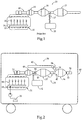
- FIG. 1 illustrates a Selective Catalytic Reduction (SCR) 13 is placeddownstream of Particulate Filter (PF) 18 for simultaneously reducing the Nitrous Oxide (NOx) and Particulate Matter (PM) from an internal combustion engine 11.
- Engine 11 is a compression ignition diesel engine equipped with a high pressure (>103.421 kPa injection pressure) common rail fuel system 12 that includes a common rail 14 and a plurality of electronically controlled fuel injectors 15. Advanced injection timing produces NOx emissions with considerable NO, and after coming in contact with the expensive rare earth elements in Oxidation Catalyst (OC) 16 a portion is converted into NO2.
- SCR Selective Catalytic Reduction
- PF Particulate Filter
- PM Particulate Matter
- an urea injector 17 sprays urea from urea tank 20 into an exhaust pipe 19 ahead of a SCR 13, which is typically a sulfur intolerant predominantly copper zeolite catalyst.
- NOx Nitrous Oxide
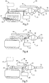
- Fig. 2 illustrates an improvement on the state-of-the-art by reversing the order of the SCR 37 and the PF 36 thereby reducing the thermal mass ahead of the SCR 37. While this arrangement removes the ability to passively regenerate utilizing NO 2, , this arrangement reduces the time required for SCR 37 catalyst to become effective. The time is reduced by the thermal mass and subsequent heat sink of the particulate filter 36 being located downstream from SCR 37. The quicker light off of the SCR 37 allows for lower amounts of Exhaust Gas Recirculation, (EGR) which is known to increase particulate generation especially during cold start up conditions.
- EGR Exhaust Gas Recirculation
- the regeneration of the PF is a non-thermal particle trap regeneration system 38, such as that described in U.S. Patent No. 7,992,382 assigned to Illinois Valley Holding Company in which regeneration is achieved via the reverse-flow of filtered exhaust gas disclosed in that patent.
- Such regeneration is instituted by closing valve 70 which may be an exhaust brake configuration or a simple on/off valve, and closing normally open valve 71.
- closing valve 70 which may be an exhaust brake configuration or a simple on/off valve
- the reverse flow goes back through the filter of the PF 36 and is directed by opening a normally closed valve 39 into a particulate volume 40 such as the pipe shown in Fig.
- Particulate volume 40 may be a settling volume, an agitated volume or even a conduit for moving the particulate matter back into the engine for burning therein.
- the regeneration of the PF 36 is ultra-efficient and operation utilizing regenerative braking forces allows for active regeneration without any decrease in the fuel economy and without oxidizing the particulate matter.
- EGR exhaust gas recirculation
- Figs. 2 and 3 illustrate embodiments in which a non-thermal actively regenerated PF 36 is located downstream of the SCR 37.
- engine exhaust gases first enter, and are treated by, the SCR 37.
- the SCR 37 substrate receives the exhaust when the exhaust is at a higher temperature so it is heated more quickly with attendant more effective utilization.
- the PF 36 is further spaced from the engine 31 and receives the exhaust after some heat has been removed. Since the filter in the PF 36 is a non-thermal regenerative type, the OC 48, SCR 37 and PF 36 are not exposed to high thermal temperatures required to burn the accumulated particulate in PF 36.
- PF 36 The downstream location of PF 36 together with the removal of thermal regeneration leads to less thermal gradients and results in longer life for the entire system.
- the NO2 is generated by the OC 48 creates what is termed the fast NOx reaction.
- a fast NOx reaction improves NOx effectiveness at lower engine exhaust temperatures but can be detrimental to NOx reduction at higher engine loads. Higher operating condition engines require less OC 48 catalyst allowing it to be coated on PF 36.
- the amount of catalyst utilized would be in the amount required to remove CO and any additional HC emissions not removed by the SCR. Since vanadium pentoxide is known to oxidize hydrocarbon emissions, the OC 48 may be eliminated except where strict emissions regulations require CO and HC reduction effectiveness. The added benefit of vanadium pentoxide is the sulfur tolerance allowing operation on high sulfur (>15 ppm) fuel typically used in developing countries. It should be noted that if a copper zeolite catalyst were utilized in the arrangement depicted in Fig. 2 , high temperature regeneration would be required for the desorption of sulfur from the copper zeolite catalyst.
- the required desorption temperature might be attained utilizing an oxy-cat thermal system utilizing OC 48 for the oxidation and temperature increase by oxidation of hydrocarbons added by either the engine 31 electronic control module or a separate burner (not shown) upstream of the OC 48, urea injector 43, or SCR 37.
- a "sulfur tolerant SCR catalyst” is one that can tolerate exhaust chemistry associated with burning of diesel fuel with a sulfur content greater than 15 parts per million of sulfur.
- vanadium pentoxide would be considered a sulfur tolerant SCR catalyst according to the present disclosure, but copper zeolite would not.
- engine system 30 may be supported on, and operably coupled to propel, a mobile vehicle 80.
- Engine system 30 includes a compression ignition diesel engine 31 with an exhaust outlet 32 fluidly connected with an after treatment system 33 that terminates at a tailpipe 34.
- a source of diesel fuel 35 is fluidly connected to the engine 31.
- the after treatment system 33 includes a particle trap or filter 36 fluidly positioned between the engine 31 and the tail pipe 34.
- a SCR catalyst 37 is positioned between the particle trap 36 and the engine 31.
- the SCR catalyst is a sulfur tolerant SCR catalyst.
- a non-thermal particle trap regeneration system 38 includes a valve 39 fluidly positioned between a particulate settling volume 40 and an inlet 41 of particle trap 36.
- a reductant system 42 includes a doser or injector 43 positioned to deliver a reductant 44, such as urea, into the after treatment system 33 upstream from the SCR catalyst 37.
- the sulfur tolerant SCR catalyst 37 is predominantly vanadium pentoxide.
- the source of diesel fuel 35 may have a sulfur content greater than 15 parts per million.
- Engine 31 may include a low pressure fuel injection system 65, such as a common rail fuel injection system 66 with a maximum injection pressure less than 103.421 kPa.
- engine system 30 is similar to that of the embodiment of Fig. 2 except that the low pressure fuel injection system 65 takes the form of a pump and line fuel injection system 67 and oxidation catalyst 48 of Fig. 2 is omitted. Otherwise, the engine system 30 is substantially similar to that of Fig. 2 . However, Fig. 3 also shows in dotted lines the reductant system 42 with a doser 43 that opens into the exhaust manifold 45 of the compression ignition diesel engine 31. This strategy may allow for even quicker treatment of NOx produced by engine 31 immediately after cold start.
- Fig. 4 illustrates an embodiment in which a non-thermal active regeneration arrangement 38, as described above in conjunction with Fig. 2 , but in which the SCR catalytic material is coated directly on the inlet channel, outlet channel, within the wall, or any catalytic coating combination of the PF substrate thereby combining the SCR NOx-reduction function with that of the PF. Increased NOx reduction effectiveness is achieved with the SCR catalyst coated on the entire substrate 51. In this manner, a separate SCR substrate as the Figs. 2 and 3 can be eliminated. The elimination of a separate SCR substrate can greatly improve the packaging flexibility and cost of the after treatment system. In other words, Fig. 4 shows a combined particle trap/SCR catalyst 55 that are positioned within a shared can 50.
- FIG. 4 The embodiment of Figure 4 is similar to that of Fig. 2 in that an oxidation catalyst 48 is positioned between reductant system 42 and engine 31.
- compression ignition diesel engine 31 may be equipped with a low pressure fuel injection system, which may be a common rail system 66 as shown in Fig. 2 or maybe a pump and line system 67 as shown in Fig. 3 .
- a low pressure fuel injection system according to the present disclosure means a system that directly injects fuel into the individual cylinders at an injection pressure less than 103.421 kPa.
- Those skilled in the art will appreciate that modern trends tend to ever higher injection pressures, which now regularly exceed 206.843 kPa. All of the other disclosed embodiments may also utilize a low pressure fuel injection system.
- Fig. 5 is similar to Fig. 4 but with the oxidation catalyst also eliminated (see OC 48 in Figs. 2 and 4 ). Elimination of the oxidation catalyst in the embodiment of Fig. 5 may permit moving the reductant system 42 so that the doser 43 is positioned to open and deliver reductant, such as urea, directly into the exhaust manifold 45 of engine 31. This may permit the reductant system 42 to become effective sooner after cold start as the higher temperatures in the exhaust manifold may permit earlier transformation of the reductant to available ammonia after injection into after treatment system 30 when entering at the exhaust manifold 45, rather than somewhere downstream in the after treatment system 30.
- reductant such as urea
- a portion of the substrate 51 for the combined SCR/PF55 may be coated with a suitable oxidation catalyst for oxidizing some hydrocarbons and carbon monoxide present in the exhaust stream. Hence multiple catalysts may be coated on the SCR/PF 55 substrate 51 of Fig. 5 .
- Fig. 6 is similar to Fig. 5 , but with an oversized combined substrate SCR/PF 56, with a substrate having a length over diameter ratio greater than one and a half.
- thermally regenerated particle traps are generally limited to a length over diameter ratio on the order of about one or less, because larger L/D ratios can lead to increased temperature gradients that result in cracking or melting of the substrate.
- the elimination of the oxidation catalyst of Fig. 4 may again permit the reductant system 42 to move upstream, such as locating the doser 43 for injection of urea into the exhaust manifold 45 for quicker NOx reduction after cold engine start.
- the oversized substrate lowers engine backpressure, improves NOx effectiveness by lowering the space velocity, and reduces ammonia slip.
- the oversizing of the SCR/PF 56 substrate is made possible, by the removal of thermal regeneration and the thermal gradients and subsequent stresses imposed by such regeneration.
- the length to diameter ratio is increased for improved packaging, such as under the floor of a vehicle 80 with improved vehicle ground clearance.
- Fig. 7 is similar to Fig. 4, 5 , and 6 but the stationary vanadium pentoxide V 2 O 5 catalysts formulas, historically utilized in stationary engines, are utilized in the combined SCR/PF 56. These catalysts are often less effective and can be permanently damaged under high engine load operation. As in the previous embodiment, the elimination of the oxidation catalyst may permit the reductant system 42 to locate the doser 43 for injection of reductant into the exhaust manifold 45. As in the embodiment of Fig. 6 , the combined SCR/PF 56 may have a length to diameter ratio greater than one and a half to further improve efficiency and reduce back pressure on engine 31. The larger L/D ratio permits effective NOx reduction at slower reaction rates.
- the exhaust can be actively or passively cooled in order to lower the maximum exhaust temperature below the level that thermal damage will occur. This may be achieved by increasing the distance, relative to the engine 31, for increased radiant and convective cooling or by active cooling methods. If an increased distance cannot be achieved due to packaging constraints, a method of cooling the engine's exhaust may be utilized.
- the use of passive cooling fins 62 exposed on an outer surface on the exhaust pipe 22, active cooling by fans 63, or a combination of passive fins 62 and active fans 63 cooling, such as an electrical or mechanical fan 63, to cool the exhaust gases under high load may be utilized.
- Fig. 8 is similar to Fig. 7 , but with the addition of a separate Passive NOx Adsorber 47, PNA catalyst applied.
- the PNA 47 adsorbs NOx emissions during engine start up when the temperatures are below the level required for effective SCR operation.
- the combined oversized SCR/PF 56 has the advantage of reaching the light off point of the catalyst at a temperature level that corresponds to the release of the NOx (desorption) from the PNA 47.
- This arrangement allows the PNA 47 and SCR/PF 56 to be placed further away from the engine lowering the maximum temperature that the SCR/PF 56 catalyst will be subjected to due to radiant and convective heat release from the exhaust pipe 22.
- the reduced temperature will ensure that the low temperature V 2 O 5 SCR catalyst is not damaged while further improving the durability and reliability of the entire exhaust aftertreatment system 33.
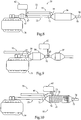
- Fig. 9 shows an engine system according to the prior art, where a Passive NOx Adsorber, PNA or similar catalyst coating is added to the PF 58.
- the PNA/PF 58 will adsorb the NOx during cold start and low temperature operation and then release the stored NOx as the temperature rises to the point where the downstream SCR 37 catalyst is at operating temperature.
- Fig. 10 is still another embodiment similar to Fig. 8 but with an oversized and sequential PNA/OC/SCR/PF 49.
- the oversizing of the PF substrate(s) in a single can enable more than one catalyst to be coated on the PF substrate.
- the first segment 74 of the PF preferably a portion of the single PF substrate, is coated with a PNA catalyst on both sides of the filter.
- the second portion 75 of the substrate filter incorporates the low temperature V 2 O 5 SCR catalyst.
- the third portion 76 may be an ammonia slip and CO catalyst coating or added as a fourth segment for simplified urea injection controls.
- the use of a low pressure fuel injection system 65 Figs.
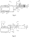
- Fig. 11 is a diagrammatic illustration of still another embodiment similar to Fig. 10 but with the single can PNA/DOC/SCR/PF 59 combination operating with a throttle generated non-thermal active regeneration approach.
- the regeneration is completed by creating a partial vacuum in settling volume 40 by closing throttle valve 82, in the engine's intake manifold 79 allowing exhaust gases to be drawn through the one-way check valve 69. Regeneration would take place on the opening of valve 39 or a combination of increased exhaust pressure can be accomplished by closing valve 70 at the time valve 82 is closed.
- the regeneration can be further enhanced by closing valve 71 before the opening of valve 39.
- Valve 71 isolates the upstream volume of exhaust gases completing with the cleaned exhaust gases reversed flow that induces the non-thermal reverse depression wave.
- the combined passive NOx adsorber/oxidation catalyst/SCR/PF 59 may be segmented and separately coated as described with regard to the embodiment of Fig. 10 .
- Fig. 11 is also of interest for showing the alternative non-thermal regeneration system 38 for regenerating the filter substrate(s) with the reverse pressure generated in a different manner.
- this non-thermal regeneration strategy may be substituted in place of or an enhancement of non-thermal regeneration system 38 discussed with the earlier embodiments.
- Fig. 12 is an embodiment of a system incorporating an exhaust energy recovery system 94 in order to increase the overall thermal efficiency.
- the utilization of the low temperature combined PNA/DOC/PF/SCR 59 or a low temperature vanadium pentoxide reduces the maximum temperature that the exhaust energy recovery system will be subjected to by removing the requirement of thermal regeneration, this improves reliability and durability while decreasing the cost of the materials required for the aftertreatment system 33. Additionally, the temperature at PNADOC/PF/SCR 59 will reduce or remove the need for active or passive cooling of the exhaust gases prior to entering the at the PNADOC/PF/SCR 59.
- the exhaust energy recovery system 94 may require the PNADOC/PF/SCR 59 to have additional PNA NOx storage capabilities due to the upstream thermal mass of the exhaust energy recovery system's heat exchangers or thermoelectric mass. While PNA/DOC/PF/SCR 59 is shown, there would be no reason why any combination of aftertreatment residing on the particulate filter substrate would not work depending on the application. urea injection might advantageously be located upstream of the exhaust energy recovery system 94 as shown dashed lines depending on the material compatibility and/or concerns for urea deposits fouling or corroding the heat exchanger 94.
- low temperature catalyst and passive NOx adsorbers significantly enhance the low temperature NOx effectiveness which will be of increased importance with the broader implementation of hybrid and engine start/stop technologies.
- the present disclosure finds general applicability for engine systems.
- the present disclosure finds specific applicability to engine systems that feature a compression ignition diesel engine and an aftertreatment system.
- the present disclosure also finds further applicability in engine systems that burn diesel fuel with a sulfur content in excess of 15 parts per million and higher.
- the present disclosure finds general applicability to any aftertreatment system that utilizes a non-thermal regeneration system to move particulate matter out of the filter and into a volume in contrast with the thermal strategies that remove particulate matter by burning the same.
- a method of operating an engine system 30 includes rapidly heating the SCR catalyst 37 faster than the particulate trap substrate 36 immediately after cold engine start up. This is accomplished by positioning the SCR catalyst 37 closer to engine 31 than the downstream particulate filter 36, or on the PF substrate. A reduction reaction with NOx with a reductant is catalyzed with the sulfur tolerant SCR catalyst 37. Particulate matter generated by burning diesel fuel in the compression ignition engine 31 is trapped in the particle trap 36. The particle trap 36 is regenerated non-thermally by moving particulate matter from within the particle trap 36, out through the inlet 41 of the particle trap 36, through the valve 39 and into the particulate settling volume 40, often without oxidizing the particulate matter.
- the exhaust temperature seen by the SCR catalyst 37 is maintained below 350° Celsius by at least one of locating the SCR catalyst 37 remotely downstream from the compression ignition diesel engine 21, by cooling the exhaust stream, and maybe by temporarily de-rating the compression ignition diesel engine 31.
- NOx reduction effectiveness may be improved by passing exhaust through an oversized particle trap 56 that is coated with the sulfur tolerant SCR catalyst and has a length over diameter ratio greater than one and a half.
- the initial occurrence of a NOx reduction reaction after engine start up may be hastened by injecting the reductant into the exhaust manifold 45 of the compression ignition diesel engine 31.
- the engine 31, because of the improved aftertreatment system 33, may be equipped with a low pressure fuel injection system with a maximum injection pressure less that 103.421 kPa.
- This fuel injection system may take the form of a common rail fuel injection system 67 ( Fig. 2 ) or a pump and line fuel injection system 66 ( Fig. 3 ) as discussed earlier.
- the SCR catalyst is a sulfur tolerant SCR catalyst
- the compression ignition diesel engine 31 may burn diesel fuel with a sulfur content of at least 15 parts per million without fouling the SCR catalyst.
- regenerating the non-thermal particle trap regeneration system 38 may retard the compression ignition diesel engine 31 by temporarily creating increased back pressure in the exhaust system or by creating a vacuum in the intake manifold, or both.
- the engine system can meet current and maybe future emissions regulation at the tailpipe 34.
- the relevant emission regulation may be at least one of the United States Environmental Protection Agency US Tier 2 Bin 5, California Air Resources Board Lev III, or European Union Euro VI. These stringent emission regulations can be met while at the same time utilizing a lower cost lower pressure fuel injection system and a less complicated and low cost aftertreatment system 33, while also utilizing a non-thermal particle trap regeneration system 38 and diesel fuel with an increased sulfur content.
- the non-thermal regeneration system 38 of the present disclosure may be performed while the engine is idling, such as when a mobile vehicle 80 is at a stop sign or stop light, or may be done while slowing the vehicle with the non-thermal regeneration system 38 providing engine breaking due to the temporarily closure of the exhaust system by closing valve 70.
- a particulate trap regeneration system which provides one or more of the following advantages: 1-Enables low temperature SCR, with maximum temperature limit constrained catalyst, operation with an actively non-thermally regenerated Particulate Filter (PF); 2-Provides faster light off the SCR catalyst for reduced emissions during startup and low temperature urban operating conditions; 3-Reduces catalyst degradation due to the removal of elevated temperature thermal regeneration cycles; 4-Reduces Exhaust Gas Recirculation (EGR) levels with the potential to eliminate the system; 5-Improves NOx effectiveness and reduces ammonia slip for possible ammonia slip catalyst removal.
- EGR Exhaust Gas Recirculation
- Engine system 30 of Fig. 2 may utilize a low pressure fuel injection system 65 in the form of a common rail fuel injection system 66.
- a low pressure fuel injection system means a system with a maximum injection pressure less that 103.421 kPa.
- hybrid vehicles can maximize their fuel economy advantage while providing low output NOx emissions.
- the engine can be shut down as often as needed with reduced NOx emissions during startup.
Description
- The present invention relates generally to engine systems exhaust after treatment and, more particularly to improved arrangements and catalyst for treating engine exhaust emissions.
- Internal Combustion engines generally, and compression ignition diesel engines specifically, produce particulate matter which is considered a waste byproduct of combustion and harmful to the environment. Governments around the world have created regulations focused on reducing the level of Particulate Matter (PM) along with Nitrous Oxides (NOx), Unburned Hydrocarbons (UHC) and Carbon Monoxide (CO). Since the formation of NOx is inversely proportional to the particulate matter being created, many technical achievements such as ultra-high fuel injection pressure systems have been developed in order to allow NOx emissions reduction technologies while maintaining or reducing particulate matter emissions. The ultra-high injection pressure (e.g.206.843 kPa or higher) creates better atomization of the fuel so that the limited oxygen available with NOx reducing technologies such as Exhaust Gas Recirculation (EGR) can be utilized for lower engine out NOx while maintaining or reducing particulate matter emissions. While ultra-high injection pressure reduces particulate matter emissions, the parasitic load on the engine is increased along with an increase in engine system cost.
- It should be noted that while the particulate mass has dropped, an increase in the number of engine out ultrafine particles increases the health risk of internal combustion engines exhaust. In order to reduce the particulate exiting the tailpipe, the current commercial state of the art engine technology has typically included a Particulate Filter (PF) to trap the particles in the engine's exhaust before being released into the atmosphere. While particulate filters have been commercially available for decades, the technologies for removing the built up particulate matter have had varying degrees of success depending on the operating cycle of the engine. This along with fuel efficiency reductions caused by the filter restriction and regeneration thermal energy, that provides no useable output work, has required government regulations to bring about the main stream commercial availability of the technology.
- Commercially available active exhaust treatment systems utilize a particulate filter which is thermally regenerated. Fuel is a convenient source of energy for such regeneration. During active filter regeneration, the exhaust gas temperature can be increased by combusting an additional quantity of fuel in the exhaust system using specialized hardware and using one of the following methods:
- Late injection combustion-Fuel is injected later in the expansion stroke so that the lower effective compression ratio produces high exhaust temperatures
- Flame combustion-the fuel is combusted in a fuel burner, usually with a dedicated supply of combustion air, with the flame entering the exhaust system.
- Catalytic combustion-the fuel is introduced through an exhaust injector, evaporated and mixed with exhaust gas, and oxidized over an oxidation catalyst.
- Combined flame and catalytic combustion-a combination of the above methods, where a fuel burner is followed by a catalytic combustion system.
- Further details can be found in "Filters Regenerated by Fuel Combustion" by W. Addy Majewski. In short, the removed particulate is burned and creates CO2 which is passed into the atmosphere.
- The current thermal solutions, described above, are overly complicated, require some method of active thermal regeneration, or require a high exhaust temperature operating cycle for thermal regeneration. These active thermal regeneration technologies utilize additional fuel use for increasing exhaust temperature which does not provide useable output work. The use of fuel, without subsequent output work, does not comply with the current global concern for Green House Gas, (GHG) Carbon Dioxide (CO2) emissions or the end user concerns over high fuel prices (operating costs). In addition to utilizing fuel, the current systems require sophisticated control algorithms, sensors, burners or dosing systems, and typically utilize finitely available and costly rare earth elements. The sustainability of such technologies is in question.
US Patent 7992382 describes using a back flow of filtered exhaust gases to regenerate the filter non-thermally. Utilization of the arrangement does not improve the NOx effectiveness of the catalyzed SCR systems. - To reduce NOx emissions, the current approach is to place a Selective Catalytic Reduction, (SCR) in the exhaust system to reduce the NOx to Nitrogen and water. This requires exhaust temperatures ranges that do not cover the entire engine operating range and do not operate effectively until they have reached temperatures above their light off temperature. Since these technologies require elevated operating temperatures typically above 250 degrees Celsius, they do not perform at start up or during low temperature stop and go urban operation. This problem is exacerbated due to current active thermal PF regeneration technologies needing partial passive regeneration to keep the fuel used for active regeneration and subsequent overall brake specific fuel consumption (BSFC) to a minimum. The current approach for passive regeneration is to use NO2 which was converted from NOx by the rare earth metals in the Oxidation Catalyst (DOC). Since NOx is only present, in sufficient quantity, before the SCR, the PF must be placed upstream of the SCR for passive thermal regeneration by NO2 to occur. The upstream position of the PF creates a heat sink in the system and reduces the rate at which the downstream SCR temperature is ramped up during startup and urban drive cycles. These first few minutes significantly contribute to the overall cycle emissions of the vehicle subsequently requiring aftertreatment that is typically greater than 90% efficient. The current high NOx effectiveness requirement, along with the removal of costly precious metals utilized in lean NOx traps, has made SCR the main technology for mobile and stationary engines.
- The current active thermal system approach has added additional constraints to the SCR catalyst that can be implemented, due to the high temperature durability concerns for SCR catalyst such as Vanadium Pentoxide. Copper Zeolite catalysts are currently utilized for SCR solutions that include thermal regeneration, while operating with ultra-low sulfur fuels, due to the catalyst's high temperature capability and reasonable sulfur tolerance to this low level of fuel sulfur. Copper zeolite catalyst, even while utilizing ultra-low sulfur (<15 ppm) fuels, require a rich air/fuel ratio sulfur regeneration event to desorb the sulfur utilizing greater than 700° Celsius temperatures. This periodic sulfur desorption regeneration requires a method of attaining a high temperature in the SCR, whether it be an oxy-cat or full burner regeneration in order to retain their performance. The regeneration requirement adds cost and complexity to the system and reduces the engine's overall thermal efficiency. Additionally, the use of exhaust energy recovery systems, are constrained by the maximum temperature required for this regeneration event to occur. The elimination of this thermal desulfation event would be a desired thermal efficiency improvement.
- Additionally, the close-coupled nature of current catalyst arrangements limit the residence time for complete urea hydrolysis making the potential for urea deposits on the catalyzed PF substrate and exhaust piping. The depositing of the urea on the particulate filter has been shown to have additional adverse effect on the NOx effectiveness after aging. In order to attain ultra-low emissions at temperatures below 200 degrees Celsius, the use of a static mixer, advanced injectors, or an increase in the distance between the injection site and the catalyst is required. Hydrolysis requires temperature and time in order to be completed. Increased distance between the urea injection site and the SCR catalyst will further improve the effectiveness of the urea hydrolysis without adding complexity to the system by means of high urea injection pressures or the aforementioned static mixer.
- Thermal aging of SCR systems is a known problem that is significantly increased by the active thermal regeneration of the particulate filter and sulfur desorption and one that requires an oversized substrate or additional catalyst material in order to achieve acceptable aged catalyst state NOx effectiveness. Additional catalyst, in the coating, increases the backpressure created by the substrate along with additional cost. While catalyst companies have been attempting to achieve higher temperatures with vanadium pentoxide catalyst, their operation still does not have the thermal durability to withstand the high temperature requirements of thermal regeneration compared to copper zeolite. The removal of high temperature regeneration for longer aftertreatment life, low temperature NOx effective catalyst, and exhaust energy recovery is desired.
- The ash accumulation, in thermal systems, that utilize a separate PF, also reduces the effectiveness of passive regeneration and increases the backpressure on the engine. The coating of the SCR catalyst on the PF substrate creates the additional performance reduction in NOx effectiveness as ash is accumulated. Since the ash accumulates near the end of the substrate, the flow of exhaust gases is reduced and then completely blocked. The reduction in flow area reduces the effective catalyst surface area/sites available resulting in reduced NOx effectiveness and passive regeneration while increasing the backpressure. Ash removal on a continuous or increase frequency is desired so as to keep this area active and functioning.
- Additionally, the ability to combine multiple aftertreatment modules into a single unit, without sacrificing NOx effectiveness or higher backpressure, requires very high porosity PF substrates. As the porosity is increased, the durability of the substrate is reduced by the high thermal regeneration temperatures and the thermal gradients imposed during the quick ramping up and down of the temperature between normal operating exhaust temperature and the required regeneration temperature set point. The removal of high temperature regeneration allows significant increases in particulate filter substrate porosity. This increase in porosity gives the required volume for additional catalyst and improved NOx effectiveness without an increase in backpressure.
- The use of a separate flow through SCR substrate downstream of the SCR catalyst coated PF has been shown, by catalyst company BASF, to increase the NOx performance by over 5% with a 50% increase in the substrate volume. Increased porosity, higher catalyst loading, and oversized substrates provide the similar benefit of increased effectiveness compared to the state-of-the-art would be desired. Particulate filters with a length to diameter ratio greater than 1.3 have been known to be damaged by excessive temperatures at the end of the filter.
- In addition to the SCR solution, it has been shown in the prior art that the use of a Passive NOx Adsorber (PNA) can trap NOx as it exits the engine under low temperature operation and then release the NOx as the temperature climbs in operating temperature. Current PNA literature states that desorption of the NOx occurs before current copper zeolite or iron zeolite based metal catalyst are capable of significant NOx reduction effectiveness. For current designs to properly function with a PNA, the PNA needs to begin desorption at 175 degrees Celsius or higher along with the close coupling of the SCR to the PNA, or alternately a SCR capable of significant NOx reduction down to 150 degrees Celsius.
- Stationary engines have long utilized a formula of vanadium pentoxide that functions well at temperature ranges between 100 degrees and 350 degrees Celsius. The lower temperature range functions very well for stationary engines where the exhaust temperature is held within a limited range of temperature. The high end of the temperature range does not correspond to the mobile market where exhaust temperatures, near the engine, can reach in excess of 450 degrees Celsius. Since maximum temperature, within the aftertreatment system, is closely linked to the location of the device to the engine, as the distance from the engine increases, radiant and convective heat losses reduce the peak temperature obtained. The aftertreatment industry has focused on the reduction of the distance between the aftertreatment and the engine in order to achieve higher temperatures in the quickest time possible. The placement of the aftertreatment near the engine has been termed close-coupled by the industry. To utilize low temperature SCR catalysts, such as the stationary vanadium pentoxide formula, the opposite must be attained. The further that the device can be positioned away from the engine, the lower the peak temperature. The exhaust temperature near the end of the exhaust system has shown to be a maximum of 203 degrees Celsius without a thermal regenerated PF compared to 418 degrees Celsius during an active thermal regeneration event. In addition to the maximum effective operating temperature constraint of around 350 degrees Celsius for the low temperature SCR catalyst, the ability to inject urea into the exhaust is limited to a temperature high enough for hydrolysis and proper mixing to be completed. The utilization of a PNA near the engine or within the SCR well downstream of the engine allows for the storage of NOx while the engine exhaust, after the PNA, reaches the threshold where the urea can be injected. Further, the increased length between the urea injection site and the SCR substrate improves the NOx reduction effectiveness by allowing for complete hydrolysis and mixing with the exhaust gases before becoming in contact with the SCR catalyst.
- Current aftertreatment systems, depending on the countries emissions regulation, further require a particulate filter, to be installed, in order to meet stringent particulate matter mass and number emissions. Since these systems currently utilize a thermal high temperature regeneration to oxidize the particulate matter, temperatures above 500 degrees Celsius are typically generated that would deactivate and damage the low temperature stationary and mobile vanadium V2O5 catalyst formulas. Assisted passive regeneration increases the temperature to a level where passive regeneration can be completed, but this approach is only utilized with systems that utilize significant passive regeneration. In order to keep the temperatures below the SCR temperature constraint, the active thermal regeneration would be required to operate downstream of the low temperature SCR catalyst. Increasing the temperature from a level below the SCR threshold to above the temperature required for carbon oxidation with oxygen would require significant additional fuel. The fuel would be oxidized utilizing a downstream oxy-cat or a fuel burner to provide the high temperatures further decreasing the overall thermal efficiency of the engine. Another potential method would be to place the PF near the engine and actively cool the exhaust or bypass the exhaust around the filter. Cooling the exhaust from these thermal regeneration temperatures to a point where effective SCR NOx reduction can occur would require a cooling system that would require too much packaging space and excessive cost. Another approach would be to bypass the low temperature catalyst at high temperatures. In order to bypass the filter during thermal regeneration without allowing NOx to be released to the environment, the filter would have to additionally be coated with a high temperature SCR catalyst and a separate urea injector installed. The increased complexity of the second sulfur intolerant SCR catalyst and urea injection site would also increase the cost and complexity of the system beyond what the market will bear. Thus, the industry has no answer in order to attain an overlapping operation of the PNA desorption and high SCR effectiveness while providing effective and efficient particulate matter regeneration. Passive regeneration is only possible in applications where the particulate matter generated is lower than the engine's passive regeneration level. Since many applications operate at low temperatures below that required for passive regeneration, an active system is still required for the remaining applications.
- In the Illinois Valley Holding Company application PCT_US_053456 (
WO 2014025647 A3 ), a throttle valve is utilized to create a pressure below that of atmospheric conditions within a particulate settling volume. While this approach alters how the differential pressure is attained, the system does not provide SCR NOx reduction capabilities but is a strategy for non-thermal regeneration of the PF. - A global solution, that has high sulfur tolerance with no increase in system temperature during regeneration, is needed so that the development costs can be shared between all markets. Additionally, as vehicles and engines are typically shipped/transferred, during the engine/vehicles useable life, from developed countries to developing countries, the aftertreatment system should be capable of operating on high sulfur fuel. Improved resale value along with the environmental advantages of the engine retaining the original ultra-low emissions will have significant global emissions reduction significance. This global issue is becoming ever more important as the engine mapping for high efficiency and subsequent high engine out NOx output is requiring high aftertreatment emissions reduction effectiveness and subsequent high emitting emissions levels if the system becomes less effective. If the aftertreatment system is not removed and modifications to the Electronic Control Module (ECM) are completed, then the aftertreatment will be poisoned by the higher sulfur level in the developing country's fuel. The NOx emissions, in particular, will be significantly higher than internal combustion engines produced even a decade ago.
- Engine aftertreatment has allowed ultra-low emissions even with high engine out emissions. The addition of aftertreatment has reduced the need for sophisticated engine combustion systems. The advantages of high pressure fuel injection for the reduction in particulate matter are reduced if the particulate filter regeneration system is efficient. The SCR catalyst NOx reduction effectiveness allows the advancement of fuel injection timing to further assist in the mixing of low pressure injected fuel and air allowing improved combustion efficiency, complete combustion, and thermally efficient engine performance. The ability to operate with increased engine out particulate levels so as to utilize lower pressure and cost fuel injection systems while still achieving NOx and PM emissions is desired. Engine performance and drivability are enhanced by increasing particulate matter generated by the engine during accelerations. Rich air/fuel ratios allow for increased power output, reducing the need for variable geometry turbochargers and their associated expense. Achieving low emissions with a low cost engine and aftertreatment system lowers the financial barrier to entry into developing markets.
- The present invention is directed toward overcoming one or more of these deficiencies of the prior art.
- In one aspect, an engine system includes a compression ignition diesel engine with an exhaust outlet fluidly connected with an aftertreatment system that terminates at a tailpipe. A source of diesel fuel is fluidly connected to the engine. The aftertreatment system includes a particle trap fluidly positioned between the engine and the tailpipe, and a SCR catalyst fluidly positioned on the particle trap or between the particle trap and the engine. The SCR catalyst is a sulfur tolerant SCR catalyst. A non-thermal particle trap regeneration system includes a valve fluidly positioned between a particulate settling volume and an inlet of the particle trap. A reductant system include a doser positioned to deliver a reductant into the aftertreatment system upstream from the SCR catalyst.
- In another aspect, a method of operating the engine system includes rapidly heating the SCR catalyst faster than the particle trap immediately after the engine start up. A reduction reaction of the NOx with the reductant is catalyzed with the sulfur tolerant SCR catalyst. Particulate matter generated by burning diesel fuel in the compression ignition diesel engine is trapped in the particle trap. The particle trap is regenerated by moving the particulate matter from within the particle trap, out through the inlet of the particle trap, through the valve and into the particulate settling volume.
-
-
Fig. 1 is a diagrammatic illustration of a system embodying the prior art approach for operating an internal combustion engine utilizing a passive and active thermal Particulate Filter (PF) regeneration along with a Selective Catalytic Reduction (SCR) for reducing the engine's NOx emissions; -
Fig. 2 is a diagrammatic illustration of a first embodiment in which a non-thermal actively regenerated PF is downstream of the SCR; -
Fig. 3 is a diagrammatic illustration of a second embodiment similar toFig. 2 bul without an Oxidation Catalyst (OC); -
Fig. 4 is a diagrammatic illustration of another embodiment of a non-thermal active regeneration arrangement in which the SCR catalytic material is coated directly on the PF substrate; -
Fig. 5 is a diagrammatic illustration of still another embodiment similar toFig. 4 but without a Oxidation Catalyst (OC); -
Fig. 6 is a diagrammatic illustration of still another embodiment similar toFig. 5 but with an oversized PF; -
Fig. 7 is a diagrammatic illustration of still another embodiment similar toFig. 6 but with optional passive and active cooling of the exhaust; -
Fig. 8 is a diagrammatic illustration of still another embodiment similar toFig. 7 but with a Passive NOx Adsorber ahead of the SCR/PF combination; -
Fig. 9 is a diagrammatic illustration of still another embodiment similar toFig. 5 ,6 ,7 , or8 but with the Passive NOx Adsorber, PNA catalyst coated directly on the PF with a downstream urea injector and SCR; -
Fig. 10 is a diagrammatic illustration of still another embodiment similar toFig. 5 ,6 ,7 , or8 but with the Passive NOx Adsorber, PNA catalyst coated directly on a high porosity and/or inlet membrane with extreme porosity PF; -
Fig. 11 is a diagrammatic illustration of still another embodiment similar toFig. 5 ,6 ,7 ,8, 9, or 10 but with the PNA/DOC/SCR/DPR combination operating with a throttle generated non-thermal active regeneration approach; -
Fig. 12 is a diagrammatic illustration of another embodiment in which an exhaust energy recovery system is utilized in addition to the PNA/DOC/SCR/DPR combination. - A prior
art engine system 10 is shown inFig. 1 which illustrates a Selective Catalytic Reduction (SCR) 13 is placeddownstream of Particulate Filter (PF) 18 for simultaneously reducing the Nitrous Oxide (NOx) and Particulate Matter (PM) from aninternal combustion engine 11.Engine 11 is a compression ignition diesel engine equipped with a high pressure (>103.421 kPa injection pressure) commonrail fuel system 12 that includes acommon rail 14 and a plurality of electronically controlledfuel injectors 15. Advanced injection timing produces NOx emissions with considerable NO, and after coming in contact with the expensive rare earth elements in Oxidation Catalyst (OC) 16 a portion is converted into NO2. Since NO2 is less stable than NO or NO3, if the temperature is above ∼350 degrees Celsius, the NO2 will react with the stored soot inPF 18 oxidizing the particulate matter into CO2. If the operating temperature is below ∼350 degrees Celsius, the particulate remains stored in thefilter 18 and is required to be cleaned by many different thermal methods including, for example, late injection of fuel into the cylinder ofengine 11 to increase the exhaust temperature typically well above the ∼250 degrees Celsius oxidation point where at least passive catalyzed passive regeneration is capable of taking place. Downstream of the PF18, anurea injector 17 sprays urea fromurea tank 20 into anexhaust pipe 19 ahead of aSCR 13, which is typically a sulfur intolerant predominantly copper zeolite catalyst. The Nitrous Oxide (NOx), in the form of NO, NO2, and NO3, then flows, in combination with the urea, that through hydrolysis has been transformed into ammonia, through theSCR 13 converting the nitrous oxide into nitrogen and water before exiting the tailpipe. -
Fig. 2 illustrates an improvement on the state-of-the-art by reversing the order of theSCR 37 and thePF 36 thereby reducing the thermal mass ahead of theSCR 37. While this arrangement removes the ability to passively regenerate utilizing NO2,, this arrangement reduces the time required forSCR 37 catalyst to become effective. The time is reduced by the thermal mass and subsequent heat sink of theparticulate filter 36 being located downstream fromSCR 37. The quicker light off of theSCR 37 allows for lower amounts of Exhaust Gas Recirculation, (EGR) which is known to increase particulate generation especially during cold start up conditions. - In the embodiments of
Figs. 2 thru 10 and 13, the regeneration of the PF is a non-thermal particletrap regeneration system 38, such as that described inU.S. Patent No. 7,992,382 assigned to Illinois Valley Holding Company in which regeneration is achieved via the reverse-flow of filtered exhaust gas disclosed in that patent. Throughout this disclosure the same number is used to identify a same or equivalent thing. Such regeneration is instituted by closingvalve 70 which may be an exhaust brake configuration or a simple on/off valve, and closing normallyopen valve 71. The reverse flow goes back through the filter of thePF 36 and is directed by opening a normally closedvalve 39 into aparticulate volume 40 such as the pipe shown inFig. 2 ,3 ,4 ,8, 9, 10 , and 13 or other components as shown in said patent.Particulate volume 40 may be a settling volume, an agitated volume or even a conduit for moving the particulate matter back into the engine for burning therein. In this non-thermal method of regeneration, the regeneration of thePF 36 is ultra-efficient and operation utilizing regenerative braking forces allows for active regeneration without any decrease in the fuel economy and without oxidizing the particulate matter. - Starting of
engine 31 creates exhaust flow and a ramped increase in exhaust temperature. Since theSCR 37 is now the first catalyzed aftertreatment, the unit heats up first allowing the unit to reach the light off temperature in a shorter period of time. Catalyst "light off' is the temperature where SCR catalyst can begin NOx emissions reduction. Emissions testing is a measurement of an emission total, so the quicker the catalyst comes up to temperature the less emissions reduction will have to be performed after the catalyst begins operating and still satisfy the relevant emissions regulation. SCR technology is typically over 90% effective. Operation at lower temperatures will allow this percentage to further increase towards an overall 95% or greater NOx reduction attailpipe 34. - One skilled in the art will recognize that an exhaust gas recirculation (EGR) is ordinarily utilized with the SCR for low temperature engine out NOx reduction along with achieving ultra-low tailpipe NOx emissions. In the hereafter disclosed arrangements, the efficiency of the SCR is raised so that the need for EGR is reduced or even precluded for some uses. Once again, this is because the effective operating temperature of the SCR is reached more quickly and retained at lower engine loads more effectively with the disclosed arrangements.
-
Figs. 2 and3 illustrate embodiments in which a non-thermal actively regeneratedPF 36 is located downstream of theSCR 37. In this arrangement, engine exhaust gases first enter, and are treated by, theSCR 37. Hence theSCR 37 substrate receives the exhaust when the exhaust is at a higher temperature so it is heated more quickly with attendant more effective utilization. Likewise, thePF 36 is further spaced from theengine 31 and receives the exhaust after some heat has been removed. Since the filter in thePF 36 is a non-thermal regenerative type, theOC 48,SCR 37 andPF 36 are not exposed to high thermal temperatures required to burn the accumulated particulate inPF 36. The downstream location ofPF 36 together with the removal of thermal regeneration leads to less thermal gradients and results in longer life for the entire system. The removal of passive thermal regeneration and subsequent temperature increase generated by oxidizing fuel with a catalyst required in some thermal regeneration methods leads to the potential removal ofOC 48, as shown inFig. 3 . This is dependent on the SCR catalyst chosen since many SCR catalyst, including Vanadium Pentoxide, are more effective with a 1:1 ratio of NO2 to NO. The NO2 is generated by theOC 48 creates what is termed the fast NOx reaction. A fast NOx reaction improves NOx effectiveness at lower engine exhaust temperatures but can be detrimental to NOx reduction at higher engine loads. Higher operating condition engines requireless OC 48 catalyst allowing it to be coated onPF 36. The amount of catalyst utilized would be in the amount required to remove CO and any additional HC emissions not removed by the SCR. Since vanadium pentoxide is known to oxidize hydrocarbon emissions, theOC 48 may be eliminated except where strict emissions regulations require CO and HC reduction effectiveness. The added benefit of vanadium pentoxide is the sulfur tolerance allowing operation on high sulfur (>15 ppm) fuel typically used in developing countries. It should be noted that if a copper zeolite catalyst were utilized in the arrangement depicted inFig. 2 , high temperature regeneration would be required for the desorption of sulfur from the copper zeolite catalyst. The required desorption temperature might be attained utilizing an oxy-cat thermalsystem utilizing OC 48 for the oxidation and temperature increase by oxidation of hydrocarbons added by either theengine 31 electronic control module or a separate burner (not shown) upstream of theOC 48,urea injector 43, orSCR 37. As used in this disclosure, a "sulfur tolerant SCR catalyst" is one that can tolerate exhaust chemistry associated with burning of diesel fuel with a sulfur content greater than 15 parts per million of sulfur. Thus, vanadium pentoxide would be considered a sulfur tolerant SCR catalyst according to the present disclosure, but copper zeolite would not. - Returning to
Fig. 2 ,engine system 30 may be supported on, and operably coupled to propel, amobile vehicle 80. In fact, any of the disclosed embodiments could likewise be supported on, and operably coupled to propel, a mobile vehicle without departing from the present disclosure.Engine system 30 includes a compressionignition diesel engine 31 with anexhaust outlet 32 fluidly connected with an aftertreatment system 33 that terminates at atailpipe 34. A source ofdiesel fuel 35 is fluidly connected to theengine 31. The aftertreatment system 33 includes a particle trap or filter 36 fluidly positioned between theengine 31 and thetail pipe 34. ASCR catalyst 37 is positioned between theparticle trap 36 and theengine 31. The SCR catalyst is a sulfur tolerant SCR catalyst. A non-thermal particletrap regeneration system 38 includes avalve 39 fluidly positioned between aparticulate settling volume 40 and aninlet 41 ofparticle trap 36. Areductant system 42 includes a doser orinjector 43 positioned to deliver areductant 44, such as urea, into the aftertreatment system 33 upstream from theSCR catalyst 37. In the illustrated embodiment, the sulfurtolerant SCR catalyst 37 is predominantly vanadium pentoxide. The source ofdiesel fuel 35 may have a sulfur content greater than 15 parts per million.Engine 31 may include a low pressurefuel injection system 65, such as a common railfuel injection system 66 with a maximum injection pressure less than 103.421 kPa. - Referring to
Fig. 3 ,engine system 30 is similar to that of the embodiment ofFig. 2 except that the low pressurefuel injection system 65 takes the form of a pump and linefuel injection system 67 andoxidation catalyst 48 ofFig. 2 is omitted. Otherwise, theengine system 30 is substantially similar to that ofFig. 2 . However,Fig. 3 also shows in dotted lines thereductant system 42 with adoser 43 that opens into theexhaust manifold 45 of the compressionignition diesel engine 31. This strategy may allow for even quicker treatment of NOx produced byengine 31 immediately after cold start. -
Fig. 4 illustrates an embodiment in which a non-thermalactive regeneration arrangement 38, as described above in conjunction withFig. 2 , but in which the SCR catalytic material is coated directly on the inlet channel, outlet channel, within the wall, or any catalytic coating combination of the PF substrate thereby combining the SCR NOx-reduction function with that of the PF. Increased NOx reduction effectiveness is achieved with the SCR catalyst coated on theentire substrate 51. In this manner, a separate SCR substrate as theFigs. 2 and3 can be eliminated. The elimination of a separate SCR substrate can greatly improve the packaging flexibility and cost of the after treatment system. In other words,Fig. 4 shows a combined particle trap/SCR catalyst 55 that are positioned within a sharedcan 50. The embodiment ofFigure 4 is similar to that ofFig. 2 in that anoxidation catalyst 48 is positioned betweenreductant system 42 andengine 31. Although not shown, compressionignition diesel engine 31 may be equipped with a low pressure fuel injection system, which may be acommon rail system 66 as shown inFig. 2 or maybe a pump andline system 67 as shown inFig. 3 . In any event, a low pressure fuel injection system according to the present disclosure means a system that directly injects fuel into the individual cylinders at an injection pressure less than 103.421 kPa. Those skilled in the art will appreciate that modern trends tend to ever higher injection pressures, which now regularly exceed 206.843 kPa. All of the other disclosed embodiments may also utilize a low pressure fuel injection system. -
Fig. 5 is similar toFig. 4 but with the oxidation catalyst also eliminated (seeOC 48 inFigs. 2 and4 ). Elimination of the oxidation catalyst in the embodiment ofFig. 5 may permit moving thereductant system 42 so that thedoser 43 is positioned to open and deliver reductant, such as urea, directly into theexhaust manifold 45 ofengine 31. This may permit thereductant system 42 to become effective sooner after cold start as the higher temperatures in the exhaust manifold may permit earlier transformation of the reductant to available ammonia after injection into aftertreatment system 30 when entering at theexhaust manifold 45, rather than somewhere downstream in the aftertreatment system 30. Although not necessary, a portion of thesubstrate 51 for the combined SCR/PF55 may be coated with a suitable oxidation catalyst for oxidizing some hydrocarbons and carbon monoxide present in the exhaust stream. Hence multiple catalysts may be coated on the SCR/PF 55substrate 51 ofFig. 5 . -
Fig. 6 is similar toFig. 5 , but with an oversized combined substrate SCR/PF 56, with a substrate having a length over diameter ratio greater than one and a half. Those skilled in the art will appreciate that thermally regenerated particle traps are generally limited to a length over diameter ratio on the order of about one or less, because larger L/D ratios can lead to increased temperature gradients that result in cracking or melting of the substrate. Like the embodiment ofFig. 5 , the elimination of the oxidation catalyst ofFig. 4 may again permit thereductant system 42 to move upstream, such as locating thedoser 43 for injection of urea into theexhaust manifold 45 for quicker NOx reduction after cold engine start. The oversized substrate lowers engine backpressure, improves NOx effectiveness by lowering the space velocity, and reduces ammonia slip. The oversizing of the SCR/PF 56 substrate is made possible, by the removal of thermal regeneration and the thermal gradients and subsequent stresses imposed by such regeneration. In particular, the length to diameter ratio is increased for improved packaging, such as under the floor of avehicle 80 with improved vehicle ground clearance. -
Fig. 7 is similar toFig. 4, 5 , and6 but the stationary vanadium pentoxide V2O5 catalysts formulas, historically utilized in stationary engines, are utilized in the combined SCR/PF 56. These catalysts are often less effective and can be permanently damaged under high engine load operation. As in the previous embodiment, the elimination of the oxidation catalyst may permit thereductant system 42 to locate thedoser 43 for injection of reductant into theexhaust manifold 45. As in the embodiment ofFig. 6 , the combined SCR/PF 56 may have a length to diameter ratio greater than one and a half to further improve efficiency and reduce back pressure onengine 31. The larger L/D ratio permits effective NOx reduction at slower reaction rates. - The exhaust can be actively or passively cooled in order to lower the maximum exhaust temperature below the level that thermal damage will occur. This may be achieved by increasing the distance, relative to the
engine 31, for increased radiant and convective cooling or by active cooling methods. If an increased distance cannot be achieved due to packaging constraints, a method of cooling the engine's exhaust may be utilized. The use ofpassive cooling fins 62 exposed on an outer surface on theexhaust pipe 22, active cooling byfans 63, or a combination ofpassive fins 62 andactive fans 63 cooling, such as an electrical ormechanical fan 63, to cool the exhaust gases under high load may be utilized. The use of passive cooling withfins 62 only has the inherent advantage of passively altering the cooling under high vehicle speeds while reducing the cooling effect during urban driving where the temperature of the exhaust should not drop below where urea can be injected with complete hydrolysis and without condensing and forming deposits on thesubstrate 51 orexhaust piping 22. The increased length between the urea injection site, which preferably upstream of the cooling system and maybe in theexhaust manifold 45, creates improved mixing and more complete hydrolysis of the urea prior to coming into contact with the SCR catalyst further improving system NOx effectiveness and durability. -
Fig. 8 is similar toFig. 7 , but with the addition of a separatePassive NOx Adsorber 47, PNA catalyst applied. ThePNA 47 adsorbs NOx emissions during engine start up when the temperatures are below the level required for effective SCR operation. The combined oversized SCR/PF 56 has the advantage of reaching the light off point of the catalyst at a temperature level that corresponds to the release of the NOx (desorption) from thePNA 47. This arrangement allows thePNA 47 and SCR/PF 56 to be placed further away from the engine lowering the maximum temperature that the SCR/PF 56 catalyst will be subjected to due to radiant and convective heat release from theexhaust pipe 22. The reduced temperature will ensure that the low temperature V2O5 SCR catalyst is not damaged while further improving the durability and reliability of the entireexhaust aftertreatment system 33. -
Fig. 9 shows an engine system according to the prior art, where a Passive NOx Adsorber, PNA or similar catalyst coating is added to thePF 58. The PNA/PF 58 will adsorb the NOx during cold start and low temperature operation and then release the stored NOx as the temperature rises to the point where thedownstream SCR 37 catalyst is at operating temperature. -
Fig. 10 is still another embodiment similar toFig. 8 but with an oversized and sequential PNA/OC/SCR/PF 49. The oversizing of the PF substrate(s) in a single can enable more than one catalyst to be coated on the PF substrate. Thefirst segment 74 of the PF, preferably a portion of the single PF substrate, is coated with a PNA catalyst on both sides of the filter. Thesecond portion 75 of the substrate filter incorporates the low temperature V2O5 SCR catalyst. With this embodiment thethird portion 76 may be an ammonia slip and CO catalyst coating or added as a fourth segment for simplified urea injection controls. The use of a low pressure fuel injection system 65 (Figs. 2 and3 ) inengine 31 is possible, in this and the other embodiments (Figs. 2-9 ), due to the effective NOx reduction by the SCR catalyst and efficient non-thermal particulate matter regeneration/cleaning of thePF substrate -
Fig. 11 is a diagrammatic illustration of still another embodiment similar toFig. 10 but with the single can PNA/DOC/SCR/PF 59 combination operating with a throttle generated non-thermal active regeneration approach. The regeneration is completed by creating a partial vacuum in settlingvolume 40 by closingthrottle valve 82, in the engine'sintake manifold 79 allowing exhaust gases to be drawn through the one-way check valve 69. Regeneration would take place on the opening ofvalve 39 or a combination of increased exhaust pressure can be accomplished by closingvalve 70 at thetime valve 82 is closed. The regeneration can be further enhanced by closingvalve 71 before the opening ofvalve 39.Valve 71 isolates the upstream volume of exhaust gases completing with the cleaned exhaust gases reversed flow that induces the non-thermal reverse depression wave. Like the embodiment ofFig. 10 , the combined passive NOx adsorber/oxidation catalyst/SCR/PF 59 may be segmented and separately coated as described with regard to the embodiment ofFig. 10 .Fig. 11 is also of interest for showing the alternativenon-thermal regeneration system 38 for regenerating the filter substrate(s) with the reverse pressure generated in a different manner. Those skilled in the art will appreciate that this non-thermal regeneration strategy may be substituted in place of or an enhancement ofnon-thermal regeneration system 38 discussed with the earlier embodiments. -
Fig. 12 is an embodiment of a system incorporating an exhaustenergy recovery system 94 in order to increase the overall thermal efficiency. The utilization of the low temperature combined PNA/DOC/PF/SCR 59 or a low temperature vanadium pentoxide reduces the maximum temperature that the exhaust energy recovery system will be subjected to by removing the requirement of thermal regeneration, this improves reliability and durability while decreasing the cost of the materials required for theaftertreatment system 33. Additionally, the temperature at PNADOC/PF/SCR 59 will reduce or remove the need for active or passive cooling of the exhaust gases prior to entering the at the PNADOC/PF/SCR 59. The exhaustenergy recovery system 94 may require the PNADOC/PF/SCR 59 to have additional PNA NOx storage capabilities due to the upstream thermal mass of the exhaust energy recovery system's heat exchangers or thermoelectric mass. While PNA/DOC/PF/SCR 59 is shown, there would be no reason why any combination of aftertreatment residing on the particulate filter substrate would not work depending on the application. urea injection might advantageously be located upstream of the exhaustenergy recovery system 94 as shown dashed lines depending on the material compatibility and/or concerns for urea deposits fouling or corroding theheat exchanger 94. - The elimination of components without eliminating their respective functions as described above is made possible because of the lower temperature operation of the non-thermal
filter regeneration system 38 along with the reduction in particulate matter allowing passive regeneration with engines due to the utilization of a passive NOx adsorber, low temperature capable sulfur tolerant SCR, and removal of EGR systems. - The addition of low temperature catalyst and passive NOx adsorbers significantly enhance the low temperature NOx effectiveness which will be of increased importance with the broader implementation of hybrid and engine start/stop technologies.
- While the combination of the different catalyst and substrates is not effected by the utilization vacuum generated regeneration of
Fig. 11 , it should be noted that the utilization of an alternate non-thermal regeneration approach utilizing a lower then atmospheric pressure settling volume can be utilized for the regeneration of the particulate filter without departing from the present disclosure. One such system is discussed inPCT US 053456 application required to induce the reverse depression wave in different, but with equivalent NOx reduction - It is now deemed apparent that there have been described multiple embodiments of an
exhaust treatment systems 33 in which the particulate filter is downstream of the SCR or combined thereby better utilizing the engine exhaust heat and storing the NOx until the temperature is available for ultra-effective SCR catalyst performance with the potential for the virtual elimination of NOx emissions at thetail pipe 34. When combined, the SCR catalyst is considered to be coated on the particulate filter substrate. - The present disclosure finds general applicability for engine systems. The present disclosure finds specific applicability to engine systems that feature a compression ignition diesel engine and an aftertreatment system. The present disclosure also finds further applicability in engine systems that burn diesel fuel with a sulfur content in excess of 15 parts per million and higher. Finally, the present disclosure finds general applicability to any aftertreatment system that utilizes a non-thermal regeneration system to move particulate matter out of the filter and into a volume in contrast with the thermal strategies that remove particulate matter by burning the same.
- Referring specifically now to the embodiments of
Figs. 2 thru 13 , a method of operating anengine system 30 includes rapidly heating theSCR catalyst 37 faster than theparticulate trap substrate 36 immediately after cold engine start up. This is accomplished by positioning theSCR catalyst 37 closer toengine 31 than the downstreamparticulate filter 36, or on the PF substrate. A reduction reaction with NOx with a reductant is catalyzed with the sulfurtolerant SCR catalyst 37. Particulate matter generated by burning diesel fuel in thecompression ignition engine 31 is trapped in theparticle trap 36. Theparticle trap 36 is regenerated non-thermally by moving particulate matter from within theparticle trap 36, out through theinlet 41 of theparticle trap 36, through thevalve 39 and into theparticulate settling volume 40, often without oxidizing the particulate matter. - In some embodiments, the exhaust temperature seen by the
SCR catalyst 37 is maintained below 350° Celsius by at least one of locating theSCR catalyst 37 remotely downstream from the compression ignition diesel engine 21, by cooling the exhaust stream, and maybe by temporarily de-rating the compressionignition diesel engine 31. NOx reduction effectiveness may be improved by passing exhaust through anoversized particle trap 56 that is coated with the sulfur tolerant SCR catalyst and has a length over diameter ratio greater than one and a half. The initial occurrence of a NOx reduction reaction after engine start up may be hastened by injecting the reductant into theexhaust manifold 45 of the compressionignition diesel engine 31. Those skilled in the art will appreciate that theengine 31, because of theimproved aftertreatment system 33, may be equipped with a low pressure fuel injection system with a maximum injection pressure less that 103.421 kPa. This fuel injection system may take the form of a common rail fuel injection system 67 (Fig. 2 ) or a pump and line fuel injection system 66 (Fig. 3 ) as discussed earlier. Because the SCR catalyst is a sulfur tolerant SCR catalyst, the compressionignition diesel engine 31 may burn diesel fuel with a sulfur content of at least 15 parts per million without fouling the SCR catalyst. - Unlike thermally regenerated particle traps, regenerating the non-thermal particle
trap regeneration system 38 may retard the compressionignition diesel engine 31 by temporarily creating increased back pressure in the exhaust system or by creating a vacuum in the intake manifold, or both. By utilizing theengine system 30 described above, the engine system can meet current and maybe future emissions regulation at thetailpipe 34. The relevant emission regulation may be at least one of the United States Environmental Protection Agency US Tier 2 Bin 5, California Air Resources Board Lev III, or European Union Euro VI. These stringent emission regulations can be met while at the same time utilizing a lower cost lower pressure fuel injection system and a less complicated and lowcost aftertreatment system 33, while also utilizing a non-thermal particletrap regeneration system 38 and diesel fuel with an increased sulfur content. Unlike thermally regenerated particle traps which require high temperatures produced by either high loads during passive regeneration or creating higher temperatures by burning fuel in the exhaust system or activating auxiliary heaters, thenon-thermal regeneration system 38 of the present disclosure may be performed while the engine is idling, such as when amobile vehicle 80 is at a stop sign or stop light, or may be done while slowing the vehicle with thenon-thermal regeneration system 38 providing engine breaking due to the temporarily closure of the exhaust system by closingvalve 70. - Advantages of Present Invention. In accordance with the present invention there is provided a particulate trap regeneration system which provides one or more of the following advantages: 1-Enables low temperature SCR, with maximum temperature limit constrained catalyst, operation with an actively non-thermally regenerated Particulate Filter (PF); 2-Provides faster light off the SCR catalyst for reduced emissions during startup and low temperature urban operating conditions; 3-Reduces catalyst degradation due to the removal of elevated temperature thermal regeneration cycles; 4-Reduces Exhaust Gas Recirculation (EGR) levels with the potential to eliminate the system; 5-Improves NOx effectiveness and reduces ammonia slip for possible ammonia slip catalyst removal. 6-Allows current and future emissions regulations to be met while operating on >15 ppm sulfur fuels ; 7-Lowers emissions for start/stop electric and hydraulic hybrid vehicles; 8-Improves overall thermal efficiency; 9-Allows for oversized length to diameter ratio SCR catalyzed particulate filters for improved NOx effectiveness, simplified controls, and low ammonia slip; 10-Allows older engine designs to meet current emissions regulations; 11-Allows retrofitting of legacy engines with the potential of meeting current emissions regulations; 12- Reduces or eliminates tailpipe out emissions increases during PF regeneration allowing more advanced timing during normal operating conditions and subsequent improvement in overall thermal efficiency; 13- Further reduces cold start NOx emissions reduction, to near zero levels, by implementing a Passive NOx Adsorber, PNA ahead of the SCR substrate or the potential PNA coating of the PF on the inlet of the combined system substrate. The resultant benefits of the above are ultra-low NOx emissions during startup and urban driving; 14- Allows the utilization of exhaust energy recovery systems with the potential for >10% improvement in overall thermal efficiency while providing an active non-thermal regenerating particulate filter. Another potential advantage is maybe the ability to inject urea directly into the exhaust manifold to shorten the time between start up and effective NOx catalytic reduction.
Engine system 30 ofFig. 2 may utilize a low pressurefuel injection system 65 in the form of a common railfuel injection system 66. As used in the present disclosure a "low pressure fuel injection system" means a system with a maximum injection pressure less that 103.421 kPa. - Additional benefits of the above are that hybrid vehicles can maximize their fuel economy advantage while providing low output NOx emissions. The engine can be shut down as often as needed with reduced NOx emissions during startup.
- It should be understood that the above description is intended for illustrative purposes only, and is not intended to limit the scope of the present disclosure in any way. Although the invention is defined by the claims set forth below, any permutation of those claims would also fall within the intended scope of the present disclosure. For instance, an engine system according to claim 1 combined with any combination of one or more of the dependent claims 2-11 would also fall within the intended scope of the present disclosure. For instance, an engine system that combined the features of claims 1, 2 and 5 would also fall within the intended scope of the present disclosure. Thus, in accordance with European practice, a patent claim that combined claims 1, 2 and 5, or any other permutation of claim 1 with any or any subset of the dependent claims 2-11 are explicitly taught in this disclosure, without the need to file this application with claims having multiple dependencies. Thus, those skilled in the art will appreciate that other aspects of the disclosure can be obtained from a study of the drawings, the disclosure and the appended claims.
Claims (14)
- An engine system (10) comprising:a compression ignition diesel engine (31) with an exhaust outlet (32) fluidly connected with an aftertreatment system (33) that terminates at a tail pipe (34);a source of diesel fuel (35) fluidly connected to the engine (31);the aftertreatment system (33) including a particle trap (36) fluidly positioned between the engine (31) and the tailpipe (34), and a non-thermal particle trap regeneration system (38) that includes a valve (39) fluidly positioned between a particulate volume (40) and an inlet (41) of the particle trap (36);characterized in thata SCR catalyst (37) fluidly is positioned on the particle trap (36) or between the particle trap (36) and the engine (31) ;wherein the SCR catalyst (37) is a sulfur tolerant SCR catalyst (37); anda reductant system (42) with a doser (43) is positioned to deliver a reductant into the aftertreatment system (33) upstream from the SCR catalyst (37).
- The engine system (10) of claim 1 wherein the sulfur tolerant SCR catalyst (37) is predominantly vanadium pentoxide; and/or
wherein the source of diesel fuel (35) is high sulfur has a sulfur content greater than fifteen parts per million of sulfur; and/or
wherein the particle trap (36) has a length over diameter ratio greater than one and a half. - The engine system (10) of claim 1 or 2, wherein the particle trap (36) and the SCR catalyst (37) are positioned within a shared can.
- The engine system (10) of claim 3, wherein the SCR catalyst (37) is coated on a substrate of the particle trap (36).
- The engine system (10) of any one of claims 1 to 4, wherein the aftertreatment system (33) includes an NOx adsorber (47) positioned upstream from the SCR catalyst.
- The engine system (10) of any one of claims 1 to 5, wherein the compression ignition diesel engine (31) includes a low pressure fuel injection system (65) with a maximum injection pressure less than 103.421 kPa.
- The engine system (10) of claim 6, wherein the low pressure fuel injection system (65) is one of a pump and line fuel injection system (66) and a common rail fuel injection system (67).
- The engine system of any one of claims 1 to 7, wherein the dozer (43) of the reductant system (42) opens into an exhaust manifold (45) of the compression ignition diesel engine (31); and/or
wherein the compression ignition diesel engine (31) is supported on, and operably coupled to propel, a mobile vehicle (80). - A method of operating an engine system (10) that includes a compression ignition diesel engine (31) with an exhaust outlet (32) fluidly connected with an aftertreatment system (33) that terminates at a tail pipe (34); a source of diesel fuel (35) fluidly connected to the engine (31); the aftertreatment system (33) including a particle trap (36) fluidly positioned between the engine (31) and the tailpipe (34), and a non-thermal particle trap regeneration system (38) that includes a valve (39) fluidly positioned between a particulate volume (40) and an inlet (41) of the particle trap (36);
characterized in that
a SCR catalyst (37) fluidly is positioned on the particle trap (36) or between the particle trap (36) and the engine (31); wherein the SCR catalyst (37) is a sulfur tolerant catalyst (37);
and a reductant system (42) with a dozer (43) positioned to deliver a reductant into the aftertreatment system (33) upstream from the SCR catalyst (37), the method comprising the steps of:rapidly heating the SCR catalyst (37) faster than the particle trap (36) immediately after engine start up;catalyzing a reduction reaction of NOx with the reductant with the sulfur tolerant SCR catalyst (37);trapping particulate matter generated by burning diesel fuel in the compression ignition diesel engine (31) in the particle trap (36);non-thermally regenerating the particle trap (36) by moving the particulate matter from within the particle trap (36), out through the inlet (41) of the particle trap (36), through the valve (39) and into the particulate settling volume (40). - The method of claim 9, including limiting an exhaust temperature seen by the SCR catalyst (37) below 350 degrees Celsius by at least one of locating the SCR catalyst (37) remotely downstream from the compression ignition diesel engine (31), cooling the exhaust stream, and temporarily de-rating the compression ignition diesel engine (31); and/or
including improving NOx reduction effectiveness by passing exhaust through the particle trap (36) that is coated with the SCR catalyst (37) and has a length over diameter ratio greater than one and a half. - The method of claim 9 or 10, including hastening an occurrence of a NOx reduction reaction by injecting a reductant into an exhaust manifold (45) of the compression ignition diesel engine (31); and/or
wherein the engine (31) is fitted with a low pressure fuel injection system (65) with a maximum injection pressure less than 103.421 kPa; and/or
including supplying the compression ignition diesel engine (31) with diesel fuel having at least fifteen parts per million of sulfur content. - The method of any one of claims 9 to 11, including retarding the compression ignition diesel engine (31) responsive to regenerating the particle trap (36).
- The method of any one of claims 9 to 12, including meeting an emissions regulation at the tail pipe (34); and
the emissions regulation is at least one of the United States Environmental Protection Agency US Tier 2 Bin 5, California Air Resources Board LEV III, and European Union Euro VI. - The method of any one of claims 9 to 13, wherein the step of regenerating the particle trap (36) is performed when the compression ignition diesel engine (31) is providing engine braking.
Applications Claiming Priority (2)
| Application Number | Priority Date | Filing Date | Title |
|---|---|---|---|
| US201562146910P | 2015-04-13 | 2015-04-13 | |
| PCT/US2016/026895 WO2016168106A1 (en) | 2015-04-13 | 2016-04-11 | Engine exhaust emissions treatment system |
Publications (2)
| Publication Number | Publication Date |
|---|---|
| EP3283740A1 EP3283740A1 (en) | 2018-02-21 |
| EP3283740B1 true EP3283740B1 (en) | 2019-07-31 |
Family
ID=55802503
Family Applications (1)
| Application Number | Title | Priority Date | Filing Date |
|---|---|---|---|
| EP16717779.9A Active EP3283740B1 (en) | 2015-04-13 | 2016-04-11 | Engine exhaust emissions treatment system |
Country Status (5)
| Country | Link |
|---|---|
| US (1) | US10294839B2 (en) |
| EP (1) | EP3283740B1 (en) |
| CN (1) | CN107787395B (en) |
| MX (1) | MX2017013268A (en) |
| WO (1) | WO2016168106A1 (en) |
Families Citing this family (14)
| Publication number | Priority date | Publication date | Assignee | Title |
|---|---|---|---|---|
| BR112019020841A2 (en) | 2017-04-04 | 2020-04-28 | Basf Corp | catalytic article of monolithic wall flow filter, vehicles, exhaust gas treatment systems and methods for treating an exhaust stream |
| IT201700124352A1 (en) * | 2017-10-31 | 2019-05-01 | Fpt Ind Spa | SYSTEM FOR FALLING WITH POLLUTANTS IN AN INTERNAL COMBUSTION ENGINE AND INTERNAL COMBUSTION ENGINE INCLUDING THE BLAST CHILLING SYSTEM |
| EP3626938A4 (en) * | 2017-10-27 | 2020-06-17 | Mitsubishi Heavy Industries Engine & Turbocharger, Ltd. | Engine oil state control device |
| WO2019174706A1 (en) * | 2018-03-12 | 2019-09-19 | Volvo Truck Corporation | Method for controlling an internal combustion engine arrangement |
| CN108625931A (en) * | 2018-05-03 | 2018-10-09 | 哈尔滨工程大学 | The effective exhaust gas processing device of low speed machine |
| CN109387377B (en) * | 2018-09-04 | 2021-05-11 | 昆明贵研催化剂有限责任公司 | Rapid aging method for catalytic gasoline particle trap |
| JP7288746B2 (en) * | 2018-09-14 | 2023-06-08 | 三菱重工エンジン&ターボチャージャ株式会社 | Exhaust gas purifiers and ships equipped with exhaust gas purifiers |
| CN109184858A (en) * | 2018-09-27 | 2019-01-11 | 潍柴动力股份有限公司 | A kind of exhaust treatment system and method |
| AT521759B1 (en) * | 2018-10-05 | 2021-12-15 | Avl List Gmbh | Method and arrangement of a gasoline engine with an improved exhaust aftertreatment through a regeneration strategy |
| US11268418B2 (en) * | 2019-01-18 | 2022-03-08 | Caterpillar Inc. | Engine system and operating strategy for selective in situ and ex situ limiting of NOx production |
| US11187127B2 (en) * | 2019-06-28 | 2021-11-30 | Deere & Company | Exhaust gas treatment system and method with four-way catalyzed filter element |
| AT523689B1 (en) * | 2020-04-08 | 2023-02-15 | Avl List Gmbh | Motor vehicle with an exhaust aftertreatment system with at least two SCR catalytic converters and method for operating such a motor vehicle |
| CN113513392A (en) * | 2021-06-04 | 2021-10-19 | 一汽解放汽车有限公司 | Active hot patching type aftertreatment system |
| US11674429B1 (en) | 2021-12-30 | 2023-06-13 | Ford Global Technologies, Llc | Method and system for controlling SCR temperature |
Family Cites Families (8)
| Publication number | Priority date | Publication date | Assignee | Title |
|---|---|---|---|---|
| JP2839851B2 (en) * | 1994-03-23 | 1998-12-16 | 日本碍子株式会社 | Exhaust gas treatment method and apparatus |
| US7992382B2 (en) * | 2003-08-01 | 2011-08-09 | Illinois Valley Holding Company | Particulate trap system and method |
| US8505277B2 (en) * | 2009-08-06 | 2013-08-13 | GM Global Technology Operations LLC | System and methods for controlling selective catalytic reduction systems |
| JP5548470B2 (en) * | 2010-02-16 | 2014-07-16 | 日本碍子株式会社 | Honeycomb catalyst body |
| US20110165040A1 (en) * | 2010-11-03 | 2011-07-07 | Ford Global Technologies, Llc | Device for remediating emissions and method of manufacture |
| WO2014025647A2 (en) * | 2012-08-08 | 2014-02-13 | Illinois Valley Holding Company | Non-thermal particulate filter regeneration |
| KR20170043514A (en) * | 2014-08-25 | 2017-04-21 | 할도르 토프쉐 에이/에스 | Method and system for the removal of particulate matter and heavy metals from engine exhaust gas |
| US9863922B2 (en) * | 2014-10-29 | 2018-01-09 | GM Global Technology Operations LLC | NOx sensor calibration and application in lean NOx trap aftertreat systems |
-
2016
- 2016-04-11 US US15/566,065 patent/US10294839B2/en active Active
- 2016-04-11 MX MX2017013268A patent/MX2017013268A/en unknown
- 2016-04-11 WO PCT/US2016/026895 patent/WO2016168106A1/en active Application Filing
- 2016-04-11 EP EP16717779.9A patent/EP3283740B1/en active Active
- 2016-04-11 CN CN201680034338.6A patent/CN107787395B/en active Active
Non-Patent Citations (1)
| Title |
|---|
| None * |
Also Published As
| Publication number | Publication date |
|---|---|
| WO2016168106A1 (en) | 2016-10-20 |
| CN107787395B (en) | 2021-06-29 |
| MX2017013268A (en) | 2018-06-19 |
| US20180135482A1 (en) | 2018-05-17 |
| CN107787395A (en) | 2018-03-09 |
| EP3283740A1 (en) | 2018-02-21 |
| US10294839B2 (en) | 2019-05-21 |
Similar Documents
| Publication | Publication Date | Title |
|---|---|---|
| EP3283740B1 (en) | Engine exhaust emissions treatment system | |
| US10113465B2 (en) | Systems and methods to reduce reductant consumption in exhaust aftertreatment systems | |
| US9677439B2 (en) | Systems and methods to mitigate NOx and HC emissions | |
| US8943807B2 (en) | Method and apparatus for cold starting an internal combustion engine | |
| JP6011224B2 (en) | Exhaust gas purification system and exhaust gas purification method | |
| US7966812B2 (en) | Multi-stage regeneration of particulate filter | |
| US8122712B2 (en) | Exhaust system with improved NOX emission control | |
| CN111255547B (en) | Exhaust gas aftertreatment system and method for exhaust gas aftertreatment of an internal combustion engine | |
| JP2006274986A (en) | Exhaust gas aftertreatment device | |
| US20140007851A1 (en) | Method of controlling an after-treatment system warm-up | |
| JP2013142363A (en) | Exhaust emission control device of diesel engine | |
| EP3354873B1 (en) | System for reducing harmful emissions of an internal combustion engine | |
| CN109209588A (en) | For adjusting burning to alleviate the system and method for exhaust excess temperature | |
| US20130180231A1 (en) | Exhaust aftertreatment system | |
| US20100319323A1 (en) | Engine aftertreatment system with exhaust lambda control | |
| JP2004176636A (en) | Exhaust emission control device for internal combustion engine | |
| Gupta et al. | Systems and methods to mitigate NO x and HC emissions | |
| BAWACHE et al. | Selection of Different Strategies of Exhaust Gas Thermal Management for Optimum Fuel Economy | |
| US20190383183A1 (en) | AFTERTREATMENT SYSTEM WITH LEAN NOx TRAP FILTER | |
| CN111305939A (en) | Exhaust gas aftertreatment device with lean NOx trap upstream of turbocharger | |
| Ren et al. | Exhaust system with improved NO X emission control | |
| JP2006274984A (en) | Exhaust gas aftertreatment device | |
| JP2004339971A (en) | Exhaust emission control method and exhaust emission control system | |
| Gui | Diesel engine as prime power for agriculture: emissions reduction for sustainable mechanization |
Legal Events
| Date | Code | Title | Description |
|---|---|---|---|
| STAA | Information on the status of an ep patent application or granted ep patent |
Free format text: STATUS: THE INTERNATIONAL PUBLICATION HAS BEEN MADE |
|
| PUAI | Public reference made under article 153(3) epc to a published international application that has entered the european phase |
Free format text: ORIGINAL CODE: 0009012 |
|
| STAA | Information on the status of an ep patent application or granted ep patent |
Free format text: STATUS: REQUEST FOR EXAMINATION WAS MADE |
|
| 17P | Request for examination filed |
Effective date: 20171110 |
|
| AK | Designated contracting states |
Kind code of ref document: A1 Designated state(s): AL AT BE BG CH CY CZ DE DK EE ES FI FR GB GR HR HU IE IS IT LI LT LU LV MC MK MT NL NO PL PT RO RS SE SI SK SM TR |
|
| AX | Request for extension of the european patent |
Extension state: BA ME |
|
| DAV | Request for validation of the european patent (deleted) | ||
| DAX | Request for extension of the european patent (deleted) | ||
| STAA | Information on the status of an ep patent application or granted ep patent |
Free format text: STATUS: EXAMINATION IS IN PROGRESS |
|
| 17Q | First examination report despatched |
Effective date: 20181019 |
|
| GRAP | Despatch of communication of intention to grant a patent |
Free format text: ORIGINAL CODE: EPIDOSNIGR1 |
|
| STAA | Information on the status of an ep patent application or granted ep patent |
Free format text: STATUS: GRANT OF PATENT IS INTENDED |
|
| INTG | Intention to grant announced |
Effective date: 20190327 |
|
| GRAS | Grant fee paid |
Free format text: ORIGINAL CODE: EPIDOSNIGR3 |
|
| GRAA | (expected) grant |
Free format text: ORIGINAL CODE: 0009210 |
|
| STAA | Information on the status of an ep patent application or granted ep patent |
Free format text: STATUS: THE PATENT HAS BEEN GRANTED |
|
| AK | Designated contracting states |
Kind code of ref document: B1 Designated state(s): AL AT BE BG CH CY CZ DE DK EE ES FI FR GB GR HR HU IE IS IT LI LT LU LV MC MK MT NL NO PL PT RO RS SE SI SK SM TR |
|
| REG | Reference to a national code |
Ref country code: CH Ref legal event code: EP Ref country code: GB Ref legal event code: FG4D |
|
| REG | Reference to a national code |
Ref country code: AT Ref legal event code: REF Ref document number: 1161127 Country of ref document: AT Kind code of ref document: T Effective date: 20190815 |
|
| REG | Reference to a national code |
Ref country code: IE Ref legal event code: FG4D |
|
| REG | Reference to a national code |
Ref country code: DE Ref legal event code: R096 Ref document number: 602016017693 Country of ref document: DE |
|
| REG | Reference to a national code |
Ref country code: NL Ref legal event code: MP Effective date: 20190731 |
|
| REG | Reference to a national code |
Ref country code: LT Ref legal event code: MG4D |
|
| REG | Reference to a national code |
Ref country code: AT Ref legal event code: MK05 Ref document number: 1161127 Country of ref document: AT Kind code of ref document: T Effective date: 20190731 |
|
| PG25 | Lapsed in a contracting state [announced via postgrant information from national office to epo] |
Ref country code: LT Free format text: LAPSE BECAUSE OF FAILURE TO SUBMIT A TRANSLATION OF THE DESCRIPTION OR TO PAY THE FEE WITHIN THE PRESCRIBED TIME-LIMIT Effective date: 20190731 Ref country code: NL Free format text: LAPSE BECAUSE OF FAILURE TO SUBMIT A TRANSLATION OF THE DESCRIPTION OR TO PAY THE FEE WITHIN THE PRESCRIBED TIME-LIMIT Effective date: 20190731 Ref country code: SE Free format text: LAPSE BECAUSE OF FAILURE TO SUBMIT A TRANSLATION OF THE DESCRIPTION OR TO PAY THE FEE WITHIN THE PRESCRIBED TIME-LIMIT Effective date: 20190731 Ref country code: AT Free format text: LAPSE BECAUSE OF FAILURE TO SUBMIT A TRANSLATION OF THE DESCRIPTION OR TO PAY THE FEE WITHIN THE PRESCRIBED TIME-LIMIT Effective date: 20190731 Ref country code: FI Free format text: LAPSE BECAUSE OF FAILURE TO SUBMIT A TRANSLATION OF THE DESCRIPTION OR TO PAY THE FEE WITHIN THE PRESCRIBED TIME-LIMIT Effective date: 20190731 Ref country code: NO Free format text: LAPSE BECAUSE OF FAILURE TO SUBMIT A TRANSLATION OF THE DESCRIPTION OR TO PAY THE FEE WITHIN THE PRESCRIBED TIME-LIMIT Effective date: 20191031 Ref country code: PT Free format text: LAPSE BECAUSE OF FAILURE TO SUBMIT A TRANSLATION OF THE DESCRIPTION OR TO PAY THE FEE WITHIN THE PRESCRIBED TIME-LIMIT Effective date: 20191202 Ref country code: BG Free format text: LAPSE BECAUSE OF FAILURE TO SUBMIT A TRANSLATION OF THE DESCRIPTION OR TO PAY THE FEE WITHIN THE PRESCRIBED TIME-LIMIT Effective date: 20191031 Ref country code: HR Free format text: LAPSE BECAUSE OF FAILURE TO SUBMIT A TRANSLATION OF THE DESCRIPTION OR TO PAY THE FEE WITHIN THE PRESCRIBED TIME-LIMIT Effective date: 20190731 |
|
| PG25 | Lapsed in a contracting state [announced via postgrant information from national office to epo] |
Ref country code: RS Free format text: LAPSE BECAUSE OF FAILURE TO SUBMIT A TRANSLATION OF THE DESCRIPTION OR TO PAY THE FEE WITHIN THE PRESCRIBED TIME-LIMIT Effective date: 20190731 Ref country code: LV Free format text: LAPSE BECAUSE OF FAILURE TO SUBMIT A TRANSLATION OF THE DESCRIPTION OR TO PAY THE FEE WITHIN THE PRESCRIBED TIME-LIMIT Effective date: 20190731 Ref country code: AL Free format text: LAPSE BECAUSE OF FAILURE TO SUBMIT A TRANSLATION OF THE DESCRIPTION OR TO PAY THE FEE WITHIN THE PRESCRIBED TIME-LIMIT Effective date: 20190731 Ref country code: GR Free format text: LAPSE BECAUSE OF FAILURE TO SUBMIT A TRANSLATION OF THE DESCRIPTION OR TO PAY THE FEE WITHIN THE PRESCRIBED TIME-LIMIT Effective date: 20191101 Ref country code: ES Free format text: LAPSE BECAUSE OF FAILURE TO SUBMIT A TRANSLATION OF THE DESCRIPTION OR TO PAY THE FEE WITHIN THE PRESCRIBED TIME-LIMIT Effective date: 20190731 |
|
| PG25 | Lapsed in a contracting state [announced via postgrant information from national office to epo] |
Ref country code: TR Free format text: LAPSE BECAUSE OF FAILURE TO SUBMIT A TRANSLATION OF THE DESCRIPTION OR TO PAY THE FEE WITHIN THE PRESCRIBED TIME-LIMIT Effective date: 20190731 |
|
| PG25 | Lapsed in a contracting state [announced via postgrant information from national office to epo] |
Ref country code: DK Free format text: LAPSE BECAUSE OF FAILURE TO SUBMIT A TRANSLATION OF THE DESCRIPTION OR TO PAY THE FEE WITHIN THE PRESCRIBED TIME-LIMIT Effective date: 20190731 Ref country code: PL Free format text: LAPSE BECAUSE OF FAILURE TO SUBMIT A TRANSLATION OF THE DESCRIPTION OR TO PAY THE FEE WITHIN THE PRESCRIBED TIME-LIMIT Effective date: 20190731 Ref country code: IT Free format text: LAPSE BECAUSE OF FAILURE TO SUBMIT A TRANSLATION OF THE DESCRIPTION OR TO PAY THE FEE WITHIN THE PRESCRIBED TIME-LIMIT Effective date: 20190731 Ref country code: EE Free format text: LAPSE BECAUSE OF FAILURE TO SUBMIT A TRANSLATION OF THE DESCRIPTION OR TO PAY THE FEE WITHIN THE PRESCRIBED TIME-LIMIT Effective date: 20190731 Ref country code: RO Free format text: LAPSE BECAUSE OF FAILURE TO SUBMIT A TRANSLATION OF THE DESCRIPTION OR TO PAY THE FEE WITHIN THE PRESCRIBED TIME-LIMIT Effective date: 20190731 |
|
| PG25 | Lapsed in a contracting state [announced via postgrant information from national office to epo] |
Ref country code: SM Free format text: LAPSE BECAUSE OF FAILURE TO SUBMIT A TRANSLATION OF THE DESCRIPTION OR TO PAY THE FEE WITHIN THE PRESCRIBED TIME-LIMIT Effective date: 20190731 Ref country code: CZ Free format text: LAPSE BECAUSE OF FAILURE TO SUBMIT A TRANSLATION OF THE DESCRIPTION OR TO PAY THE FEE WITHIN THE PRESCRIBED TIME-LIMIT Effective date: 20190731 Ref country code: IS Free format text: LAPSE BECAUSE OF FAILURE TO SUBMIT A TRANSLATION OF THE DESCRIPTION OR TO PAY THE FEE WITHIN THE PRESCRIBED TIME-LIMIT Effective date: 20200224 Ref country code: SK Free format text: LAPSE BECAUSE OF FAILURE TO SUBMIT A TRANSLATION OF THE DESCRIPTION OR TO PAY THE FEE WITHIN THE PRESCRIBED TIME-LIMIT Effective date: 20190731 |
|
| REG | Reference to a national code |
Ref country code: DE Ref legal event code: R097 Ref document number: 602016017693 Country of ref document: DE |
|
| PLBE | No opposition filed within time limit |
Free format text: ORIGINAL CODE: 0009261 |
|
| STAA | Information on the status of an ep patent application or granted ep patent |
Free format text: STATUS: NO OPPOSITION FILED WITHIN TIME LIMIT |
|
| PG2D | Information on lapse in contracting state deleted |
Ref country code: IS |
|
| PG25 | Lapsed in a contracting state [announced via postgrant information from national office to epo] |
Ref country code: IS Free format text: LAPSE BECAUSE OF FAILURE TO SUBMIT A TRANSLATION OF THE DESCRIPTION OR TO PAY THE FEE WITHIN THE PRESCRIBED TIME-LIMIT Effective date: 20191030 |
|
| 26N | No opposition filed |
Effective date: 20200603 |
|
| PG25 | Lapsed in a contracting state [announced via postgrant information from national office to epo] |
Ref country code: SI Free format text: LAPSE BECAUSE OF FAILURE TO SUBMIT A TRANSLATION OF THE DESCRIPTION OR TO PAY THE FEE WITHIN THE PRESCRIBED TIME-LIMIT Effective date: 20190731 |
|
| PG25 | Lapsed in a contracting state [announced via postgrant information from national office to epo] |
Ref country code: MC Free format text: LAPSE BECAUSE OF FAILURE TO SUBMIT A TRANSLATION OF THE DESCRIPTION OR TO PAY THE FEE WITHIN THE PRESCRIBED TIME-LIMIT Effective date: 20190731 |
|
| REG | Reference to a national code |
Ref country code: CH Ref legal event code: PL |
|
| PG25 | Lapsed in a contracting state [announced via postgrant information from national office to epo] |
Ref country code: LI Free format text: LAPSE BECAUSE OF NON-PAYMENT OF DUE FEES Effective date: 20200430 Ref country code: LU Free format text: LAPSE BECAUSE OF NON-PAYMENT OF DUE FEES Effective date: 20200411 Ref country code: CH Free format text: LAPSE BECAUSE OF NON-PAYMENT OF DUE FEES Effective date: 20200430 |
|
| REG | Reference to a national code |
Ref country code: BE Ref legal event code: MM Effective date: 20200430 |
|
| PG25 | Lapsed in a contracting state [announced via postgrant information from national office to epo] |
Ref country code: BE Free format text: LAPSE BECAUSE OF NON-PAYMENT OF DUE FEES Effective date: 20200430 |
|
| PG25 | Lapsed in a contracting state [announced via postgrant information from national office to epo] |
Ref country code: IE Free format text: LAPSE BECAUSE OF NON-PAYMENT OF DUE FEES Effective date: 20200411 |
|
| PG25 | Lapsed in a contracting state [announced via postgrant information from national office to epo] |
Ref country code: MT Free format text: LAPSE BECAUSE OF FAILURE TO SUBMIT A TRANSLATION OF THE DESCRIPTION OR TO PAY THE FEE WITHIN THE PRESCRIBED TIME-LIMIT Effective date: 20190731 Ref country code: CY Free format text: LAPSE BECAUSE OF FAILURE TO SUBMIT A TRANSLATION OF THE DESCRIPTION OR TO PAY THE FEE WITHIN THE PRESCRIBED TIME-LIMIT Effective date: 20190731 |
|
| PG25 | Lapsed in a contracting state [announced via postgrant information from national office to epo] |
Ref country code: MK Free format text: LAPSE BECAUSE OF FAILURE TO SUBMIT A TRANSLATION OF THE DESCRIPTION OR TO PAY THE FEE WITHIN THE PRESCRIBED TIME-LIMIT Effective date: 20190731 |
|
| PGFP | Annual fee paid to national office [announced via postgrant information from national office to epo] |
Ref country code: FR Payment date: 20230417 Year of fee payment: 8 Ref country code: DE Payment date: 20230424 Year of fee payment: 8 |
|
| PGFP | Annual fee paid to national office [announced via postgrant information from national office to epo] |
Ref country code: GB Payment date: 20230413 Year of fee payment: 8 |