EP3283721B1 - Motorised drive device for a closure or solar protection home-automation facility, associated home-automation facility and method for controlling the operation of such a device - Google Patents
Motorised drive device for a closure or solar protection home-automation facility, associated home-automation facility and method for controlling the operation of such a device Download PDFInfo
- Publication number
- EP3283721B1 EP3283721B1 EP16716230.4A EP16716230A EP3283721B1 EP 3283721 B1 EP3283721 B1 EP 3283721B1 EP 16716230 A EP16716230 A EP 16716230A EP 3283721 B1 EP3283721 B1 EP 3283721B1
- Authority
- EP
- European Patent Office
- Prior art keywords
- electromechanical actuator
- power supply
- photovoltaic cell
- control unit
- drive device
- Prior art date
- Legal status (The legal status is an assumption and is not a legal conclusion. Google has not performed a legal analysis and makes no representation as to the accuracy of the status listed.)
- Active
Links
- 238000000034 method Methods 0.000 title claims description 11
- 238000004804 winding Methods 0.000 claims description 18
- 238000001514 detection method Methods 0.000 claims description 15
- 238000004088 simulation Methods 0.000 claims description 12
- 230000002618 waking effect Effects 0.000 claims description 4
- 230000005611 electricity Effects 0.000 claims 15
- 238000011017 operating method Methods 0.000 claims 8
- 238000005286 illumination Methods 0.000 claims 1
- 230000037072 sun protection Effects 0.000 description 14
- 230000001419 dependent effect Effects 0.000 description 6
- 238000009434 installation Methods 0.000 description 4
- 230000006978 adaptation Effects 0.000 description 2
- 238000005096 rolling process Methods 0.000 description 2
- 241001080024 Telles Species 0.000 description 1
- 230000005540 biological transmission Effects 0.000 description 1
- 238000004891 communication Methods 0.000 description 1
- 230000007547 defect Effects 0.000 description 1
- 238000006073 displacement reaction Methods 0.000 description 1
- 238000005265 energy consumption Methods 0.000 description 1
- 239000004744 fabric Substances 0.000 description 1
- 239000000463 material Substances 0.000 description 1
- 239000007769 metal material Substances 0.000 description 1
- 238000012986 modification Methods 0.000 description 1
- 230000004048 modification Effects 0.000 description 1
- 239000000615 nonconductor Substances 0.000 description 1
- 230000035484 reaction time Effects 0.000 description 1
- 238000011084 recovery Methods 0.000 description 1
- 230000000475 sunscreen effect Effects 0.000 description 1
- 239000000516 sunscreening agent Substances 0.000 description 1
- 230000000007 visual effect Effects 0.000 description 1
Images


Classifications
-
- E—FIXED CONSTRUCTIONS
- E06—DOORS, WINDOWS, SHUTTERS, OR ROLLER BLINDS IN GENERAL; LADDERS
- E06B—FIXED OR MOVABLE CLOSURES FOR OPENINGS IN BUILDINGS, VEHICLES, FENCES OR LIKE ENCLOSURES IN GENERAL, e.g. DOORS, WINDOWS, BLINDS, GATES
- E06B9/00—Screening or protective devices for wall or similar openings, with or without operating or securing mechanisms; Closures of similar construction
- E06B9/56—Operating, guiding or securing devices or arrangements for roll-type closures; Spring drums; Tape drums; Counterweighting arrangements therefor
- E06B9/68—Operating devices or mechanisms, e.g. with electric drive
- E06B9/72—Operating devices or mechanisms, e.g. with electric drive comprising an electric motor positioned inside the roller
-
- E—FIXED CONSTRUCTIONS
- E06—DOORS, WINDOWS, SHUTTERS, OR ROLLER BLINDS IN GENERAL; LADDERS
- E06B—FIXED OR MOVABLE CLOSURES FOR OPENINGS IN BUILDINGS, VEHICLES, FENCES OR LIKE ENCLOSURES IN GENERAL, e.g. DOORS, WINDOWS, BLINDS, GATES
- E06B9/00—Screening or protective devices for wall or similar openings, with or without operating or securing mechanisms; Closures of similar construction
- E06B9/24—Screens or other constructions affording protection against light, especially against sunshine; Similar screens for privacy or appearance; Slat blinds
- E06B2009/2476—Solar cells
-
- E—FIXED CONSTRUCTIONS
- E06—DOORS, WINDOWS, SHUTTERS, OR ROLLER BLINDS IN GENERAL; LADDERS
- E06B—FIXED OR MOVABLE CLOSURES FOR OPENINGS IN BUILDINGS, VEHICLES, FENCES OR LIKE ENCLOSURES IN GENERAL, e.g. DOORS, WINDOWS, BLINDS, GATES
- E06B9/00—Screening or protective devices for wall or similar openings, with or without operating or securing mechanisms; Closures of similar construction
- E06B9/56—Operating, guiding or securing devices or arrangements for roll-type closures; Spring drums; Tape drums; Counterweighting arrangements therefor
- E06B9/68—Operating devices or mechanisms, e.g. with electric drive
- E06B2009/6809—Control
-
- G—PHYSICS
- G08—SIGNALLING
- G08C—TRANSMISSION SYSTEMS FOR MEASURED VALUES, CONTROL OR SIMILAR SIGNALS
- G08C17/00—Arrangements for transmitting signals characterised by the use of a wireless electrical link
- G08C17/02—Arrangements for transmitting signals characterised by the use of a wireless electrical link using a radio link
Definitions
- the present invention relates to a motorized drive device for a home automation system for closing or sun protection.
- the present invention also relates to a home automation closure or sun protection system comprising a roll-up screen, by means of such a motorized driving device, on a winding tube rotated by an electromechanical actuator, and a method operating control of such a motorized drive device.
- the present invention relates to the field of occultation devices comprising a motorized drive device moving a screen between at least a first position and a second position.
- a motorized driving device comprises an electromechanical actuator of a movable closure, concealment or sun protection element such as a shutter, a door, a grating, a blind or any other equivalent equipment, hereafter called a screen .
- the autonomous electric power supply device comprises a battery and a photovoltaic cell.
- the electromechanical actuator is electrically connected to the autonomous electric power supply device.
- the electronic control unit comprises a wireless control command receiving module.
- the electronic control unit is configured to detect information transmitted via an electrical power supply line connecting the photovoltaic cell to the electromechanical actuator by means of a switch positioned on the power supply line as well as by means of elements for detecting variations in the voltage on the power supply line.
- this motorized drive device has the disadvantage of adding a switch positioned on the power supply line connecting the photovoltaic cell to the electromechanical actuator to inhibit the operation of the control command receiving module without wire, so as to limit the consumption of electrical energy by the electronic control unit and to avoid the discharge of the battery, between the moment of assembly of the motorized drive device at the factory and the time of commissioning of the motorized drive device in the home automation system for closing or sun protection.
- the object of the present invention is to solve the aforementioned drawbacks and to propose a motorized drive device for a home automation system for closing or sun protection, a home automation system for closing or associated sun protection, as well as a control method in which operation of such a device to reduce the consumption of electrical energy by an electronic control unit and to avoid the discharge of at least one battery, between the time of assembly of the motor drive device in the factory and the time of commissioning of the motorized drive device in the home automation system for closing or sun protection, as well as when using the motorized drive device put into service in the home automation system for closing or sunscreen.
- the measuring elements of a quantity related to the electrical power supply of the electromechanical actuator by said at least one photovoltaic cell make it possible to detect periods of power supply and power supply interruption of the power supply.
- electromechanical actuator from said at least one photovoltaic cell so as to use said at least one photovoltaic cell, and in particular the supply of electrical energy delivered by it to the electromechanical actuator, to awaken the electronic unit of control or place the electronic control unit in a standby mode.
- the inputs and outputs of the electronic control unit are scanned at a predetermined periodicity lower than that used when the measuring elements detect the power supply of the control unit.
- the electronic control unit enters a standby mode, so as to reduce the consumption of electrical energy by the electronic control unit and to avoid the discharge of said at least one battery.
- the motorized driving device is suitable for to be ordered.
- the electronic control unit can be reset, at least partially, by executing a sequence of periods of power supply and power failure of the electromechanical actuator, where the periods of power and cut electrical power supply of the electromechanical actuator are determined through measuring elements measuring a quantity related to the supply of electrical energy of the electromechanical actuator by said at least one photovoltaic cell.
- At least part of the data stored by the electronic control unit is reset, following the detection by the measuring elements of a sequence of periods respectively corresponding to the presence or absence of the connecting electrical connection. said at least one photovoltaic cell to the electromechanical actuator.
- the electronic control unit comprises a wireless command command receiving module.
- the present invention aims, according to a second aspect, a home automation closure or sun protection system comprising a screen rollable by means of a motorized drive device according to the invention on a winding tube rotated by an actuator electromechanical.
- This home automation system has characteristics and advantages similar to those described above in connection with the motorized drive device according to the invention.
- This control method has characteristics and advantages similar to those described above in connection with the motorized drive device according to the invention.
- the sequence of periods of power supply and power failure of the electromechanical actuator is simulated by the connection and disconnection of a first electrical connector connected to the at least one photovoltaic cell. cooperating with a second electrical connector connected to the electronic control unit.
- the sequence of periods of power supply and power failure of the electromechanical actuator is simulated by means of an external electrical power source, where the power source external electrical energy is electrically connected to the electromechanical actuator to replace said at least one photovoltaic cell.
- the sequence of periods of power supply and power failure of the electromechanical actuator is simulated by removing a cover element from said at least one photovoltaic cell and positioning the covering said at least one photovoltaic cell.
- the electronic control unit comprises a wireless control command receiving module
- this module is inhibited, following the detection by the electronic control unit of the power supply power failure of the control unit. electromechanical actuator from said at least one photovoltaic cell.
- the wireless command command receiving module is woken up according to a predetermined periodicity, so as to detect control commands transmitted to the electronic control unit.
- the predetermined periodicity of awakening of the wireless control command receiving module is dependent on the luminous power determined by means of the measuring elements measuring a quantity related to the electrical power supply of the electromechanical actuator by said at least one photovoltaic cell.
- the predetermined wakeup periodicity of the wireless control command receiving module is dependent on the charge level of said at least one battery.
- a home automation system according to the invention and installed in a building having an opening 1, window or door, equipped with a screen 2 belonging to a concealment device 3, in particular a motorized roller shutter.
- the concealment device 3 may be a rolling shutter, a fabric blind or with adjustable blades, or a rolling gate.
- the present invention applies to all types of occulting device.
- the screen 2 of the occulting device 3 is wound on a winding tube 4 driven by a motorized drive device 5 and movable between a wound position, particularly high, and a unwound position, particularly low.
- the movable screen 2 of the concealment device 3 is a closure, concealment and / or sun protection screen, winding on the winding tube 4, the inner diameter is substantially equivalent to the outer diameter of an electromechanical actuator 11, so that the electromechanical actuator 11 can be inserted into the winding tube 4, during assembly of the occulting device 3.
- the motorized drive device 5 comprises the electromechanical actuator 11, in particular of the tubular type, making it possible to rotate the winding tube 4, so as to unroll or wind up the screen 2 of the occulting device 3.
- the concealment device 3 comprises the winding tube 4 for winding the screen 2, where, in the mounted state, the electromechanical actuator 11 is inserted into the winding tube 4.
- the shutter which forms the concealment device 3
- the shutter comprises an apron comprising horizontal blades articulated to each other, forming the screen 2 of the shutter 3, and guided by two lateral rails 6. These blades are joined when the deck 2 of the shutter 3 reaches its low position unrolled.
- the wound up position corresponds to the support of a final L-shaped end plate 8 of the deck 2 of the shutter 3 against an edge of a box 9 of the shutter 3
- the lowered low position corresponds to the support of the final end blade 8 of the deck 2 of the shutter 3 against a threshold 7 of the opening 1.
- the first blade of the shutter 3, opposite to the end plate, is connected to the winding tube 4 by means of at least one hinge 10.
- the winding tube 4 is disposed inside the trunk 9 of the roller shutter 3.
- the apron 2 of the roller shutter 3 winds and unwinds around the winding tube 4 and is housed at least in part at the inside the trunk 9.
- the box 9 is disposed above the opening 1, or in the upper part of the opening 1.
- the motor drive device 5 is controlled by a control unit.
- the control unit may be, for example, a local control unit 12, where the local control unit 12 may be wired or wirelessly connected to a central control unit 13.
- the central control unit 13 controls the local control unit 12, as well as other similar local control units distributed throughout the building.
- the central control unit 13 may be in communication with a remote weather station outside the building, including, in particular, one or more sensors that can be configured to determine, for example, a temperature, a brightness, or a speed Wind.
- a remote control 14 which may be a type of local control unit, and provided with a control keyboard, which comprises means of selection and display, further allows a user to intervene on the actuator electromechanical 11 and / or the central control unit 13.
- the motorized drive device 5 is preferably configured to execute the unwinding or winding commands of the screen 2 of the concealment device 3, which can be transmitted, in particular, by the remote control unit 14.
- the electromechanical actuator 11 comprises an electric motor 16.
- the electric motor 16 comprises a rotor and a stator, not shown and positioned coaxially around an axis of rotation X, which is also the axis of rotation of the tube. winding 4 in mounted configuration of the motorized drive device 5.
- Control means of the electromechanical actuator 11 according to the invention, allowing the displacement of the screen 2 of the concealment device 3, are constituted by at least one electronic control unit 15.
- This electronic control unit 15 is adapted to operate the electric motor 16 of the electromechanical actuator 11, and, in particular, to allow the electric power supply of the electric motor 16.
- the electronic control unit 15 controls, in particular, the electric motor 16, so as to open or close the screen 2, as described above.
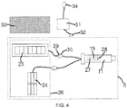
- the electronic control unit 15 also comprises a control command receiving module 27, as illustrated in FIG. figure 4 , the control commands being issued by a command transmitter, such as the remote control 14 intended to control the electromechanical actuator 11.
- control command reception module 27 of the electronic control unit 15 is of wireless type.
- control command receiving module 27 is configured to receive radio control commands.
- the command order receiving module 27 may also allow the reception of control commands transmitted by wire means.
- the control means of the electromechanical actuator 11 comprise hardware and / or software means.
- the hardware means may comprise at least one microcontroller.
- the electromechanical actuator 11 is supplied with electrical energy by means of at least one battery 24, which can be recharged by at least one photovoltaic cell 25, as illustrated in FIG. figure 4 .
- the electromechanical actuator 11 makes it possible to move the screen 2 of the occulting device 3.
- the electromechanical actuator 11 comprises a power supply cable 18 allowing its supply of electrical energy from the battery or batteries 24.
- a housing 17 of the electromechanical actuator 11 is preferably of cylindrical shape.
- the housing 17 is made of a metallic material.
- the housing material of the electromechanical actuator is not limiting and may be different and, in particular, plastic.
- the electromechanical actuator 11 also comprises a gear reduction device 19 and an output shaft 20.
- the electromechanical actuator 11 may also include a limit and / or obstacle detection device, which may be mechanical or electronic.
- the electric motor 16 and the gear reduction device 19 are disposed inside the casing 17 of the electromechanical actuator 11.
- the output shaft 20 of the electromechanical actuator 11 is disposed inside the winding tube 4, and at least partly outside the casing 17 of the electromechanical actuator 11.
- the output shaft 20 of the electromechanical actuator 11 is coupled by connecting means 22 to the winding tube 4, in particular a wheel-shaped connection means.
- the electromechanical actuator 11 also comprises a shutter element 21 at one end of the casing 17.
- the casing 17 of the electromechanical actuator 11 is fixed to a support 23, in particular a cheek, of the trunk 9 of the concealment device 3 by means of the closure element 21 forming a torque support, in particular a shutter head and torque recovery.
- the closure element 21 is also called a fixed point of the electromechanical actuator 11.
- the electronic control unit 15 is arranged, in other words integrated, inside the housing 17 of the electromechanical actuator 11.
- the electronic control unit 15 is disposed outside the housing 17 of the electromechanical actuator 11 and, in particular, mounted on the support 23 or in the closure element 21.
- the motorized drive device 5 comprises an autonomous electric power supply device 26.
- the electromechanical actuator 11 is electrically connected to the autonomous electric power supply device 26.
- the autonomous electric power supply device 26 comprises the battery or batteries 24 and the photovoltaic cell or cells 25.
- each battery 24 is disposed inside the trunk 9 of the concealment device 3.
- the expression “the battery 24” is used to designate one or more batteries according to the configuration of the autonomous electric power supply device 26.
- the expression “the photovoltaic cell 25” is used to designate one or more photovoltaic cells according to the configuration of the autonomous electric power supply device 26.
- the photovoltaic cell 25 is electrically connected directly to the electronic control unit 15.
- the battery 24 is electrically connected directly to the electronic control unit 15.
- the photovoltaic cell 25 is electrically connected to the battery 24.
- the battery 24 is electrically connected to the electronic control unit 15.
- the battery 24 is rechargeable type and supplies electrical energy to the electromechanical actuator 11. And the battery 24 is supplied with electrical energy by the photovoltaic cell 25.
- the recharging of the battery 24 is implemented by solar energy by means of the photovoltaic cell 25.
- the battery 24 can be recharged without having to dismount part of the trunk 9 of the concealment device 3.
- the motorized drive device 5 and, in particular, the photovoltaic cell 25 comprises loading elements configured to charge the battery 24 from the solar energy recovered by the photovoltaic cell 25.
- the charging elements configured to charge the battery 24 from solar energy convert the solar energy recovered by the photovoltaic cell 25 into electrical energy.
- the autonomous electric power supply device 26 comprises a plurality of photovoltaic cells 25 constituting a photovoltaic panel.
- the electric power supply of the electromechanical actuator 11 by the battery 24 can be substituted for an electrical power supply of the electromechanical actuator 11 by an electrical power supply network.
- the supply of electrical energy of the electromechanical actuator 11 by the battery 24 eliminates a connection to the power supply network.
- the electrical power supply of the electromechanical actuator 11 is implemented, on the one hand, by an electrical energy supply network and, on the other hand, by the battery 24.
- the supply of electrical energy of the electromechanical actuator 11 by the battery 24 makes it possible, in particular, to provide for a power supply cut-off of the electromechanical actuator 11 by an electrical power supply network.
- the electromechanical actuator 11 is supplied with electrical energy, on the one hand, by means of a power supply cable connected to the electrical energy supply network and, on the other hand, by the battery 24. .
- the supply of electrical energy to the electromechanical actuator 11 via an electrical energy supply network makes it possible to recharge the battery 24, in particular when the battery 24 is insufficiently recharged by the photovoltaic cell 25.
- the electronic control unit 15 is configured to detect periods of power supply and power supply interruption of the electromechanical actuator 11 from the photovoltaic cell 25, only by means of measuring elements 28. a quantity related to the supply of electrical energy of the electromechanical actuator 11 by this photovoltaic cell 25.
- a power supply period of the electromechanical actuator 11 from the photovoltaic cell 25 corresponds to the presence of the electrical connection connecting the photovoltaic cell 25 to the electromechanical actuator 11.
- a power supply cut-off period of the electromechanical actuator 11 from the photovoltaic cell 25 corresponds to the absence of the electrical connection connecting the photovoltaic cell 25 to the electromechanical actuator 11.
- the absence of the connecting electrical connection the photovoltaic cell 25 with the electromechanical actuator 11 may be due to the withdrawal of the photovoltaic cell 25 with respect to the autonomous electric power supply device 26, at the interruption of the electrical connection between the photovoltaic cell 25 and the electromechanical actuator 11, or the loss of electrical connection between the photovoltaic cell 25 and the electromechanical actuator 11.
- the measuring elements 28 of a magnitude related to the electrical power supply of the electromechanical actuator 11 by the photovoltaic cell 25 make it possible to detect periods of power supply and power supply interruption of the power supply.
- the measuring elements 28 of a magnitude related to the electrical power supply of the electromechanical actuator 11 by the photovoltaic cell 25 detect the power supply cutoff of the electromechanical actuator 11 from of the photovoltaic cell 25, the inputs and outputs of the electronic control unit 15, in particular of a microcontroller, are scanned at a predetermined periodicity lower than that used when the measuring elements 28 detect the supply of electrical energy of the electromechanical actuator 11 from the photovoltaic cell 25, or even not scanned, so as to reduce the consumption of electrical energy by the electronic control unit 15 and to avoid the discharge of the battery 24.
- the electronic control unit 15 enters a standby mode, so as to reduce the consumption of electrical energy by the electronic control unit 15 and to avoid the discharge of the battery 24.
- Detection of the power supply cut-off of the electromechanical actuator 11 from the photovoltaic cell 25 by the measuring elements 28 makes it possible to diagnose a fault related to the power supply of the electromechanical actuator 11 by the photovoltaic cell 25 and, in particular, to signal this defect by a visual and / or audible signal.
- the motor drive device 5 is controllable.
- the periods of power supply and power failure of the electromechanical actuator 11 are detected by means of a direct electrical connection between the measuring elements 28 and the photovoltaic cell 25 and, in particular, without the quantity measured by the measuring elements 28 passes through other elements constituting the autonomous electric power supply device 26, such as, for example, the battery 24.
- the detection of supply or of the power supply cut-off of the electromechanical actuator 11 from the photovoltaic cell 25 is implemented by measuring, through the measuring elements 28, a quantity related to the supply of electrical energy delivered by the photovoltaic cell 25.
- the magnitude related to the supply of electrical energy delivered by the photovoltaic cell 25 may be, in particular, a voltage, a current or an impedance.
- the value of the quantity related to the supply of electrical energy of the electromechanical actuator 11 by the photovoltaic cell 25 is proportional to the light power sensed by the photovoltaic cell 25, in other words, the value of this quantity supplying electrical energy l
- the electromechanical actuator 11 is dependent on the light intensity of the solar energy sensed by the photovoltaic cell 25.
- the measuring elements 28 form an integral part of the electronic control unit 15.
- the measuring elements 28 may comprise either a voltage divider, a comparator and a microcontroller, one of whose inputs is provided with an analog-digital converter, in the case where the measured quantity is a voltage, a shunt resistor and a microcontroller, one of whose inputs is provided with an analog-digital converter, in the case where the measured quantity is a current.
- the electronic control unit 15 is also configured to reset to the least part of the data stored by the electronic control unit 15, following the simulation of a sequence of power supply periods and power supply power failure of the electromechanical actuator 11, where the power periods and power supply failure are detected through the measuring elements 28.
- the electronic control unit 15 can be reset, at least partially, by executing a sequence of periods of power supply and power failure of the electromechanical actuator 11, where the periods of power and power supply power failure of the electromechanical actuator 11 are determined through the measuring elements 28 measuring a quantity related to the supply of electrical energy of the electromechanical actuator 11 by the photovoltaic cell 25.
- the data memorized by the electronic control unit 15 that can be reset can be the end-of-travel positions of the screen 2, the obstacle detection threshold or thresholds, or the paired control units 12, 13, 14. with the electromechanical actuator 11.
- the sequence of periods of power supply and power failure of the electromechanical actuator 11 is simulated by the connection and disconnection of a first electrical connector 29 connected to the photovoltaic cell 25 cooperating with a second electrical connector 30 connected to the electronic control unit 15.
- a power supply period of the electromechanical actuator 11 by the photovoltaic cell 25 is implemented by the electrical connection of the first electrical connector 29 connected to the at least one photovoltaic cell 25 with the second connected electrical connector 30. to the electronic control unit 15.
- a period of power supply power failure of the electromechanical actuator 11 from the photovoltaic cell 25 is implemented by the electrical disconnection of the first electrical connector 29 connected to the at least one photovoltaic cell 25 with respect to the second electrical connector 30 connected to the electronic control unit 15.
- the measuring elements 28 measure a quantity related to the supply of electrical energy delivered by the photovoltaic cell 25.
- the value of the measured quantity is greater than a threshold value, this means that the photovoltaic cell 25 captures light rays.
- the first electrical connector 29 connected to the at least one photovoltaic cell 25 is disconnected from the second electrical connector 30 connected to the electronic control unit 15, the value of the measured quantity is zero and therefore less than a threshold value, it means that the photovoltaic cell 25 does not pick up light rays.
- the first electrical connector 29 is connected to the photovoltaic cell 25 by means of a power supply cable.
- the second electrical connector 30 is connected to the electronic control unit 15 by means of a power supply cable.
- the first and second electrical connectors 29, 30 respectively connected to said at least one photovoltaic cell 25 and to the electronic control unit 15 are accessible, in particular by dismounting a part of the box 9 of the device. occultation 3.
- the sequence of periods of power supply and power supply power failure of the electromechanical actuator 11 is simulated by means of an external electrical power supply source 31.
- the source of external electric power supply 31 is electrically connected to the electromechanical actuator 11 in replacement of the photovoltaic cell 25.
- a power supply period of the electromechanical actuator 11 by the external electric power supply source 31 is implemented either by the electrical connection of the second electrical connector 30 connected to the electronic control unit 15 with a third electrical connector 32 connected to the external electrical power supply source 31, or by closing a switch of the external electric power supply source 31.
- a period of power supply power failure of the electromechanical actuator 11 from the external electric power supply source 31 is implemented either by the electrical disconnection of the second electrical connector 30 connected to the electronic control unit 15 with respect to the third electrical connector 32 connected to the external electric power supply source 31, or by opening the interrupte of the external electric power supply 31.
- the measuring elements 28 measure a quantity related to the supply of electrical energy delivered by the external electric power supply source 31.
- the second electrical connector 30 connected to the electronic control unit 15 is connected on the third electrical connector 32 connected to the external electric power supply source 31, or when the switch of the external electric power supply source 31 is closed, the value of the measured quantity is greater than a threshold value .
- the second electrical connector 30 connected to the electronic control unit 15 is disconnected from the third electrical connector 32 connected to the external electrical power supply source 31, or when the switch of the external electrical power supply source 31 is open, the value of the measured quantity is zero and therefore less than a threshold value.
- the first electrical connector 29 is connected to the at least one photovoltaic cell 25 by means of a power supply cable.
- the second electrical connector 30 is connected to the electronic control unit 15 by means of a power supply cable.
- the third electrical connector 32 is connected to the external electric power source 31 by means of a power supply cable.
- the simulation of the sequence of periods of power supply and power failure of the electromechanical actuator 11 by means of the external electric power supply source 31 is implemented when the photovoltaic cell 25 is faulty or when the photovoltaic cell 25 is not installed in the motorized drive device 5, in particular during an after-sales service intervention or during the assembly of the motorized drive device 5.
- the first, second and third electrical connectors 29, 30, 32 respectively connected to said at least one photovoltaic cell 25, to the electronic control unit 15 and to the external electric power supply source. 31 are accessible, in particular by removing a portion of the trunk 9 of the occulting device 3.
- the external electric power supply source 31 may be a transformer electrically connected to the power supply network, so as to transform an alternating voltage into a DC voltage.
- the AC voltage of the mains or mains voltage has, for example, a value of 230 VRMS (peak value of 325V) for the French power grid.
- the mains voltage may have values different, depending on the power grid of the country where the home automation system is located.
- the DC supply voltage of the electromechanical actuator 11, obtained at the output of the transformer may be, for example, 12 V.
- a power supply period of the electromechanical actuator 11 by the external electric power supply source 31 is implemented by the electrical connection of an electrical outlet 34 connected to the power supply source.
- a power supply power failure period of the electromechanical actuator 11 from the external electric power supply source 31 is implemented by the electrical disconnection of the electrical outlet 34 connected at the source of external electric power supply 31 with respect to the power supply connected to the power supply network.
- the electrical outlet 34 is connected to the external electric power supply source 31 by means of a power supply cable.
- the sequence of periods of power supply and power failure of the electromechanical actuator 11 is simulated by removing a cover member 33 from the photovoltaic cell 25 and positioning the covering 33 on the photovoltaic cell 25.
- a power supply period of the electromechanical actuator 11 by the photovoltaic cell 25 is implemented by the removal of the covering element 33 placed on the photovoltaic cell 25.
- a period of power failure the electrical energy of the electromechanical actuator 11 from the photovoltaic cell 25 is implemented by the positioning of the covering element 33 on the photovoltaic cell 25.
- the measuring elements 28 measure a quantity related to the supply of electrical energy delivered by the photovoltaic cell 25.
- the value of the measured quantity is greater than a threshold value, it means that the photovoltaic cell 25 captures light rays.
- the covering element 33 is placed on the photovoltaic cell 25, the value of the measured quantity is below a threshold value, this means that the photovoltaic cell 25 does not pick up or not enough light rays.
- the first and second electrical connectors 29, 30 respectively connected to said at least one photovoltaic cell 25 and to the electronic control unit 15 may not be accessible.
- the first, second and third electrical connectors 29, 30, 32 respectively connected to the at least one photovoltaic cell 25, to the electronic control unit 15 and to the power supply source external 31 are arranged at the level of the support 23 and, in particular, inside the trunk 9 of the concealment device 3, following the assembly of the motorized drive device 5 in the concealment device 3.
- the electronic control unit 15 comprises the wireless control command reception module 27.
- the wireless command command receiving module 27 is inhibited, following detection by the electronic control unit 15 of the power supply cut-off of the electromechanical actuator 11 from the cell photovoltaic 25.
- the electronic control unit 15 enters a so-called deep sleep mode so as to inhibit the wireless control command reception module 27.
- the passage into a so-called deep sleep mode following the detection of the power supply power failure of the electromechanical actuator 11 from the photovoltaic cell 25 by the measuring elements 28 reduces the consumption of electrical energy by the electronic control unit 15 and to avoid the discharge of the battery 24.
- the wireless command command receiving module 27 is woken up according to a predetermined periodicity, so as to detect issued command commands, in particular by a command command transmitter which can be for example the remote control 14, to destination of the electronic control unit 15.
- a command command transmitter which can be for example the remote control 14, to destination of the electronic control unit 15.
- the waking up of the wireless control command receiving module 27 according to a predetermined periodicity is preferably implemented in a so-called active standby mode of the electronic control unit 15, so as to temporarily inhibit the module receiving wireless command orders 27.
- the so-called active standby mode of the electronic control unit 15 is implemented, preferably, when the measuring elements 28 of a magnitude related to the electrical power supply of the electromechanical actuator 11 by the photovoltaic cell 25 detect the supply of electrical energy of the electromechanical actuator 11 from the photovoltaic cell 25, and when the wireless command control receiving module 27 has received no order to order, following the flow of a predetermined period of time.
- the predetermined wake-up period of the wireless control command receiving module 27 is dependent on the light output determined by means of the measuring elements 28 measuring a magnitude related to the power supply. of the electromechanical actuator 11 by the photovoltaic cell 25.
- the adaptation of the wake-up period of the wireless control command receiving module 27 as a function of the light power determined by means of the measuring elements 28 makes it possible to reduce the electrical energy consumption by the electronic control unit 15 and to limit the discharge of the battery 24.
- the wake-up period of the wireless control command receiving module 27 is lengthened during the night and reduced during the day, so as to reduce the power consumption by the electronic control unit 15 at the same time. during the night and to ensure reactive operation of the motorized drive device 5 during the day.
- the predetermined wakeup periodicity of the wireless control command receiving module 27 can take a plurality of defined values as a function of threshold values of light power.
- the wakeup periodicity of the wireless control command receiving module 27 may be of the order of 150 milliseconds when the light power determined by means of the measuring elements 28 is less than 10 W / m 2 , of 70 milliseconds when the luminous power determined by means of the measuring elements 28 is between 10 W / m 2 and 200 W / m 2 , and 20 milliseconds when the light power determined by means of the measuring elements 28 is greater than 200 W / m 2 .
- the predetermined wake up period of the wireless control command receiving module 27 is dependent on the level of charge of the battery 24.
- the adaptation of the wake-up period of the wireless command command receiving module 27 as a function of the charge level of the battery 24 makes it possible to reduce the consumption of electrical energy by the electronic control unit 15 and to avoid the discharge of the battery 24.
- reaction time of the motorized drive device 5 following the transmission of a control command, in particular from the remote control 14, allows the user to deduce the battery charge level. 24, since the wake-up period of the wireless control command reception module 27 is longer or shorter, depending on the charge level of the battery 24.
- the predetermined wake-up period of the wireless control command receiving module 27 is dependent, on the one hand, on the light power determined by means of the measuring elements 28 measuring a linked magnitude. to the supply of electrical energy of the electromechanical actuator 11 by the photovoltaic cell 25 and, on the other hand, of the charge level of the battery 24.
- the wakeup periodicity of the wireless control command receiving module 27 may be of the order of 150 milliseconds when the light power determined by means of the measuring elements 28 is less than 10 W / m 2 and that the charge level of the battery 24 is greater than or equal to 50%, of 300 milliseconds when the light power determined by means of the measuring elements 28 is less than 10 W / m 2 and the level charge of the battery 24 is less than 50%.
- the control method comprises a step of detecting periods of supply and power supply interruption of the electromechanical actuator 11 from the photovoltaic cell 25.
- This detection step is carried out only by means of the measuring elements 28 of a magnitude related to the supply of electrical energy to the electromechanical actuator 11 by said at least one photovoltaic cell 25.
- the electronic control unit 15 Following the detection of a power supply period of the electromechanical actuator 11 from the photovoltaic cell 25, the electronic control unit 15 enters a sleep mode, called active, in which the inputs and outputs of the electronic control unit 15, in particular a microcontroller, are scanned at a predetermined periodicity. And, in particular, the wireless command command receiving module 27 is woken up according to a predetermined periodicity, so as to receive a command command issued by a command command transmitter, which can be for example the remote control 14.
- a command command transmitter which can be for example the remote control 14.
- the electronic control unit 15 enters a sleep mode, called deep, during of which the inputs and outputs of the electronic control unit 15, in particular of a microcontroller, are scanned at a predetermined periodicity which is lower than that of the so-called active standby mode implemented following the detection of a period supplying electrical energy to the electromechanical actuator 11 from the photovoltaic cell 25.
- the wireless command command receiving module 27 is inhibited, so as to reduce the electrical power consumption by the electronic control unit 15 and to avoid the discharge of the battery 24.
- the predetermined periodicity of scanning of the inputs and outputs of the electronic control unit 15, in particular of a microcontroller, and, in particular, of the waking up of the wireless control command receiving module 27 is reduced, when the measuring elements 28 measure a zero value or a value lower than a threshold value of the quantity related to the electrical energy supply of the electromechanical actuator 11 by the photovoltaic cell 25.
- the control method also comprises a step of simulating a sequence of periods of power supply and power supply cut-off of the electromechanical actuator 11, where the periods of power supply and power supply cutoff are detected through the measuring elements 28.
- This simulation step can be implemented by the connection and disconnection of the first electrical connector 29 connected to the at least one photovoltaic cell 25 cooperating with the second electrical connector 30 connected to the electronic control unit 15, by means of the external electric power supply source 31 electrically connected to the electromechanical actuator 11 instead of the photovoltaic cell 25, or by the positioning or removal of the covering element 33 on the photovoltaic cell 25.
- the control method comprises a step of resetting at least a portion of the data stored by the electronic control unit 15, following the execution of the simulation step.
- the sequence of feeding and power supply cut-off of the electromechanical actuator 11 comprises a first power supply interruption period for a predetermined period of time, which can be of the order of two seconds, a power supply period during a predetermined period of time, which may be of the order of seven seconds, and a second period of power supply interruption for a predetermined period of time, which may be of the order of two seconds.
- At least part of the data stored by the electronic control unit 15 can be reset, in particular as soon as the predetermined period of time of the second power failure period electrical energy has passed.
- the measuring elements of a quantity related to the electrical power supply of the electromechanical actuator by the photovoltaic cell make it possible to detect periods of power supply and power supply interruption of the electromechanical actuator.
- electromechanical actuator from the photovoltaic cell so as to use the photovoltaic cell, and in particular the supply of electrical energy delivered by it to the electromechanical actuator, to wake up the electronic control unit or to place the electronic control unit in a standby mode.
- the present invention also makes it possible to reinitialize, at least partially, the data stored by the electronic control unit by executing a sequence of periods of power supply and power supply interruption of the electromechanical actuator, where the periods of power supply and power supply power failure of the electromechanical actuator are determined through the measuring elements measuring a quantity related to the supply of electrical energy of the electromechanical actuator by the photovoltaic cell.
- the battery may be a unitary battery or a group of batteries connected by means of an electrical insulator.
Landscapes
- Engineering & Computer Science (AREA)
- Structural Engineering (AREA)
- Architecture (AREA)
- Civil Engineering (AREA)
- Charge And Discharge Circuits For Batteries Or The Like (AREA)
- Control Of Electrical Variables (AREA)
Description
La présente invention concerne un dispositif d'entraînement motorisé pour une installation domotique de fermeture ou de protection solaire.The present invention relates to a motorized drive device for a home automation system for closing or sun protection.
La présente invention concerne également une installation domotique de fermeture ou de protection solaire comprenant un écran enroulable, au moyen d'un tel dispositif d'entraînement motorisé, sur un tube d'enroulement entraîné en rotation par un actionneur électromécanique, ainsi qu'un procédé de commande en fonctionnement d'un tel dispositif d'entraînement motorisé.The present invention also relates to a home automation closure or sun protection system comprising a roll-up screen, by means of such a motorized driving device, on a winding tube rotated by an electromechanical actuator, and a method operating control of such a motorized drive device.
De manière générale, la présente invention concerne le domaine des dispositifs d'occultation comprenant un dispositif d'entraînement motorisé mettant en mouvement un écran entre au moins une première position et une deuxième position.In general, the present invention relates to the field of occultation devices comprising a motorized drive device moving a screen between at least a first position and a second position.
Un dispositif d'entraînement motorisé comprend un actionneur électromécanique d'un élément mobile de fermeture, d'occultation ou de protection solaire tel qu'un volet, une porte, une grille, un store ou tout autre matériel équivalent, appelé par la suite écran.A motorized driving device comprises an electromechanical actuator of a movable closure, concealment or sun protection element such as a shutter, a door, a grating, a blind or any other equivalent equipment, hereafter called a screen .
On connaît déjà le document
L'unité électronique de contrôle est configurée pour détecter des informations transmises via une ligne d'alimentation en énergie électrique reliant la cellule photovoltaïque à l'actionneur électromécanique au moyen d'un interrupteur positionné sur la ligne d'alimentation électrique ainsi qu'au moyen d'éléments de détection des variations de la tension sur la ligne d'alimentation en énergie électrique.The electronic control unit is configured to detect information transmitted via an electrical power supply line connecting the photovoltaic cell to the electromechanical actuator by means of a switch positioned on the power supply line as well as by means of elements for detecting variations in the voltage on the power supply line.
Cependant, ce dispositif d'entraînement motorisé présente l'inconvénient d'ajouter un interrupteur positionné sur la ligne d'alimentation en énergie électrique reliant la cellule photovoltaïque à l'actionneur électromécanique pour inhiber le fonctionnement du module de réception d'ordres de commande sans fil, de sorte à limiter la consommation d'énergie électrique par l'unité électronique de contrôle et à éviter la décharge de la batterie, entre le moment de l'assemblage du dispositif d'entraînement motorisé en usine et le moment de la mise en service du dispositif d'entraînement motorisé dans l'installation domotique de fermeture ou de protection solaire.However, this motorized drive device has the disadvantage of adding a switch positioned on the power supply line connecting the photovoltaic cell to the electromechanical actuator to inhibit the operation of the control command receiving module without wire, so as to limit the consumption of electrical energy by the electronic control unit and to avoid the discharge of the battery, between the moment of assembly of the motorized drive device at the factory and the time of commissioning of the motorized drive device in the home automation system for closing or sun protection.
Ainsi, l'ajout de cet interrupteur engendre un surcoût sur le dispositif d'entraînement motorisé.Thus, the addition of this switch generates an additional cost on the motorized drive device.
En outre, l'utilisation d'un tel interrupteur nécessite de pouvoir accéder à celui-ci, suite à l'assemblage du dispositif d'entraînement motorisé, en particulier dans un coffre de l'installation domotique de fermeture ou de protection solaire.In addition, the use of such a switch requires access to it, following the assembly of the motorized drive device, in particular in a trunk of the home automation system for closing or sun protection.
La présente invention a pour but de résoudre les inconvénients précités et de proposer un dispositif d'entraînement motorisé pour une installation domotique de fermeture ou de protection solaire, une installation domotique de fermeture ou de protection solaire associée, ainsi qu'un procédé de commande en fonctionnement d'un tel dispositif permettant de réduire la consommation d'énergie électrique par une unité électronique de contrôle et d'éviter la décharge d'au moins une batterie, entre le moment de l'assemblage du dispositif d'entraînement motorisé en usine et le moment de la mise en service du dispositif d'entraînement motorisé dans l'installation domotique de fermeture ou de protection solaire, ainsi que lors de l'utilisation du dispositif d'entraînement motorisé mis en service dans l'installation domotique de fermeture ou de protection solaire.The object of the present invention is to solve the aforementioned drawbacks and to propose a motorized drive device for a home automation system for closing or sun protection, a home automation system for closing or associated sun protection, as well as a control method in which operation of such a device to reduce the consumption of electrical energy by an electronic control unit and to avoid the discharge of at least one battery, between the time of assembly of the motor drive device in the factory and the time of commissioning of the motorized drive device in the home automation system for closing or sun protection, as well as when using the motorized drive device put into service in the home automation system for closing or sunscreen.
A cet égard, la présente invention vise, selon un premier aspect, un dispositif d'entraînement motorisé pour une installation domotique de fermeture ou de protection solaire comprenant :
- un actionneur électromécanique,
- une unité électronique de contrôle,
- un dispositif d'alimentation en énergie électrique autonome, le dispositif d'alimentation en énergie électrique autonome comprenant au moins une batterie et au moins une cellule photovoltaïque,
∘ où l'actionneur électromécanique est relié électriquement au dispositif d'alimentation en énergie électrique autonome.
- an electromechanical actuator,
- an electronic control unit,
- an autonomous electric power supply device, the autonomous electric power supply device comprising at least one battery and at least one photovoltaic cell,
Where the electromechanical actuator is electrically connected to the autonomous electric power supply device.
Selon l'invention, l'unité électronique de contrôle est configurée pour :
- détecter des périodes d'alimentation et de coupure d'alimentation en énergie électrique de l'actionneur électromécanique à partir de ladite au moins une cellule photovoltaïque, uniquement au moyen d'éléments de mesure d'une grandeur liée à l'alimentation en énergie électrique de l'actionneur électromécanique par ladite au moins une cellule photovoltaïque, et
- réinitialiser au moins une partie des données mémorisées par l'unité électronique de contrôle, suite à la simulation d'une séquence de périodes d'alimentation et de coupure d'alimentation en énergie électrique de l'actionneur électromécanique, où les périodes d'alimentation et de coupure d'alimentation en énergie électrique sont détectées au travers des éléments de mesure.
- detecting periods of power supply and power supply failure of the electromechanical actuator from said at least one photovoltaic cell, only by means of measuring elements of a magnitude related to the supply of electrical energy of the electromechanical actuator by said at least one photovoltaic cell, and
- reset at least a portion of the data stored by the electronic control unit, following the simulation of a sequence of power supply periods and power failure of the electromechanical actuator, where the periods of power and power supply failure are detected through the measuring elements.
Ainsi, les éléments de mesure d'une grandeur liée à l'alimentation en énergie électrique de l'actionneur électromécanique par ladite au moins une cellule photovoltaïque permettent de détecter des périodes d'alimentation et de coupure d'alimentation en énergie électrique de l'actionneur électromécanique à partir de ladite au moins une cellule photovoltaïque, de sorte à utiliser ladite au moins une cellule photovoltaïque, et en particulier l'alimentation en énergie électrique délivrée par celle-ci à l'actionneur électromécanique, pour réveiller l'unité électronique de contrôle ou encore placer l'unité électronique de contrôle dans un mode de veille.Thus, the measuring elements of a quantity related to the electrical power supply of the electromechanical actuator by said at least one photovoltaic cell make it possible to detect periods of power supply and power supply interruption of the power supply. electromechanical actuator from said at least one photovoltaic cell, so as to use said at least one photovoltaic cell, and in particular the supply of electrical energy delivered by it to the electromechanical actuator, to awaken the electronic unit of control or place the electronic control unit in a standby mode.
De cette manière, lorsque les éléments de mesure d'une grandeur liée à l'alimentation en énergie électrique de l'actionneur électromécanique par ladite au moins une cellule photovoltaïque détectent la coupure d'alimentation en énergie électrique de l'actionneur électromécanique à partir de ladite au moins une cellule photovoltaïque, les entrées et sorties de l'unité électronique de contrôle, en particulier d'un microcontrôleur, sont scrutées selon une périodicité prédéterminée inférieure à celle utilisée lorsque les éléments de mesure détectent l'alimentation en énergie électrique de l'actionneur électromécanique à partir de ladite au moins une cellule photovoltaïque, voire non scrutées, de sorte à réduire la consommation d'énergie électrique par l'unité électronique de contrôle et à éviter la décharge de ladite au moins une batterie.In this way, when the measuring elements of a quantity related to the electrical power supply of the electromechanical actuator by said at least one photovoltaic cell detect the power failure of the electromechanical actuator from said at least one photovoltaic cell, the inputs and outputs of the electronic control unit, in particular a microcontroller, are scanned at a predetermined periodicity lower than that used when the measuring elements detect the power supply of the control unit. electromechanical actuator from said at least one photovoltaic cell, or even non-scanned, so as to reduce the consumption of electrical energy by the electronic control unit and to avoid the discharge of said at least one battery.
Dès que les éléments de mesure d'une grandeur liée à l'alimentation en énergie électrique de l'actionneur électromécanique par ladite au moins une cellule photovoltaïque détectent la coupure d'alimentation en énergie électrique de l'actionneur électromécanique à partir de ladite au moins une cellule photovoltaïque, l'unité électronique de contrôle entre dans un mode de veille, de sorte à réduire la consommation d'énergie électrique par l'unité électronique de contrôle et à éviter la décharge de ladite au moins une batterie.As soon as the measuring elements of a quantity related to the electrical power supply of the electromechanical actuator by said at least one photovoltaic cell detect the power supply cutoff of the electromechanical actuator from said at least one photovoltaic cell. a photovoltaic cell, the electronic control unit enters a standby mode, so as to reduce the consumption of electrical energy by the electronic control unit and to avoid the discharge of said at least one battery.
Lorsque les éléments de mesure d'une grandeur liée à l'alimentation en énergie électrique de l'actionneur électromécanique par ladite au moins une cellule photovoltaïque détectent l'alimentation en énergie électrique de l'actionneur électromécanique à partir de ladite au moins une cellule photovoltaïque, le dispositif d'entraînement motorisé est apte à être commandé.When the measuring elements of a quantity related to the electrical power supply of the electromechanical actuator by said at least one photovoltaic cell detect the supply of electrical energy of the electromechanical actuator from said at least one photovoltaic cell , the motorized driving device is suitable for to be ordered.
En outre, l'unité électronique de contrôle peut être réinitialisée, au moins partiellement, en exécutant une séquence de périodes d'alimentation et de coupure d'alimentation en énergie électrique de l'actionneur électromécanique, où les périodes d'alimentation et de coupure d'alimentation en énergie électrique de l'actionneur électromécanique sont déterminées au travers des éléments de mesure mesurant une grandeur liée à l'alimentation en énergie électrique de l'actionneur électromécanique par ladite au moins une cellule photovoltaïque.In addition, the electronic control unit can be reset, at least partially, by executing a sequence of periods of power supply and power failure of the electromechanical actuator, where the periods of power and cut electrical power supply of the electromechanical actuator are determined through measuring elements measuring a quantity related to the supply of electrical energy of the electromechanical actuator by said at least one photovoltaic cell.
De cette manière, au moins une partie des données mémorisées par l'unité électronique de contrôle sont réinitialisées, suite à la détection par les éléments de mesure d'une séquence de périodes correspondant respectivement à la présence ou à l'absence du branchement électrique reliant ladite au moins une cellule photovoltaïque à l'actionneur électromécanique.In this way, at least part of the data stored by the electronic control unit is reset, following the detection by the measuring elements of a sequence of periods respectively corresponding to the presence or absence of the connecting electrical connection. said at least one photovoltaic cell to the electromechanical actuator.
Avantageusement, l'unité électronique de contrôle comprend un module de réception d'ordres de commande sans fil.Advantageously, the electronic control unit comprises a wireless command command receiving module.
La présente invention vise, selon un deuxième aspect, une installation domotique de fermeture ou de protection solaire comprenant un écran enroulable au moyen d'un dispositif d'entraînement motorisé conforme à l'invention sur un tube d'enroulement entraîné en rotation par un actionneur électromécanique.The present invention aims, according to a second aspect, a home automation closure or sun protection system comprising a screen rollable by means of a motorized drive device according to the invention on a winding tube rotated by an actuator electromechanical.
Cette installation domotique présente des caractéristiques et avantages analogues à ceux décrits précédemment en relation avec le dispositif d'entraînement motorisé selon l'invention.This home automation system has characteristics and advantages similar to those described above in connection with the motorized drive device according to the invention.
Enfin, la présente invention vise, selon un troisième aspect, un procédé de commande en fonctionnement d'un dispositif d'entraînement motorisé pour une installation domotique de fermeture ou de protection solaire, le dispositif d'entraînement motorisé comprenant :
- un actionneur électromécanique,
- une unité électronique de contrôle,
- un dispositif d'alimentation en énergie électrique autonome, le dispositif d'alimentation en énergie électrique autonome comprenant au moins une batterie et au moins une cellule photovoltaïque,
∘ où l'actionneur électromécanique est relié électriquement au dispositif d'alimentation en énergie électrique autonome.
- an electromechanical actuator,
- an electronic control unit,
- an autonomous electric power supply device, the autonomous electric power supply device comprising at least one battery and at least one photovoltaic cell,
Where the electromechanical actuator is electrically connected to the autonomous electric power supply device.
Selon l'invention, ledit procédé comprend au moins les étapes suivantes :
- détection de périodes d'alimentation et de coupure d'alimentation en énergie électrique de l'actionneur électromécanique à partir de ladite au moins une cellule photovoltaïque, uniquement au moyen d'éléments de mesure d'une grandeur liée à l'alimentation en énergie électrique de l'actionneur électromécanique par ladite au moins une cellule photovoltaïque,
- simulation d'une séquence de périodes d'alimentation et de coupure d'alimentation en énergie électrique de l'actionneur électromécanique, où les périodes d'alimentation et de coupure d'alimentation en énergie électrique sont détectées au travers des éléments de mesure, et
- réinitialisation d'au moins une partie des données mémorisées par l'unité électronique de contrôle, suite à l'exécution de l'étape de simulation.
- detection of periods of power supply and power failure electromechanical actuator electrically from said at least one photovoltaic cell, only by means of measuring elements of a magnitude related to the supply of electrical energy of the electromechanical actuator by said at least one photovoltaic cell,
- simulating a sequence of power supply periods and power failure of the electromechanical actuator, wherein the periods of supply and power failure are detected through the measuring elements, and
- reset of at least a portion of the data stored by the electronic control unit, following the execution of the simulation step.
Ce procédé de commande présente des caractéristiques et avantages analogues à ceux décrits précédemment en relation avec le dispositif d'entraînement motorisé selon l'invention.This control method has characteristics and advantages similar to those described above in connection with the motorized drive device according to the invention.
Dans un premier mode de réalisation, la séquence de périodes d'alimentation et de coupure d'alimentation en énergie électrique de l'actionneur électromécanique est simulée par le branchement et le débranchement d'un premier connecteur électrique relié à ladite au moins une cellule photovoltaïque coopérant avec un deuxième connecteur électrique relié à l'unité électronique de contrôle.In a first embodiment, the sequence of periods of power supply and power failure of the electromechanical actuator is simulated by the connection and disconnection of a first electrical connector connected to the at least one photovoltaic cell. cooperating with a second electrical connector connected to the electronic control unit.
Dans un deuxième mode de réalisation, la séquence de périodes d'alimentation et de coupure d'alimentation en énergie électrique de l'actionneur électromécanique est simulée au moyen d'une source d'alimentation en énergie électrique externe, où la source d'alimentation en énergie électrique externe est reliée électriquement à l'actionneur électromécanique en remplacement de ladite au moins une cellule photovoltaïque.In a second embodiment, the sequence of periods of power supply and power failure of the electromechanical actuator is simulated by means of an external electrical power source, where the power source external electrical energy is electrically connected to the electromechanical actuator to replace said at least one photovoltaic cell.
Dans un troisième mode de réalisation, la séquence de périodes d'alimentation et de coupure d'alimentation en énergie électrique de l'actionneur électromécanique est simulée en retirant un élément de recouvrement de ladite au moins une cellule photovoltaïque et en positionnant l'élément de recouvrement sur ladite au moins une cellule photovoltaïque.In a third embodiment, the sequence of periods of power supply and power failure of the electromechanical actuator is simulated by removing a cover element from said at least one photovoltaic cell and positioning the covering said at least one photovoltaic cell.
En pratique, lorsque l'unité électronique de contrôle comprend un module de réception d'ordres de commande sans fil, ce module est inhibé, suite à la détection par l'unité électronique de contrôle de la coupure d'alimentation en énergie électrique de l'actionneur électromécanique à partir de ladite au moins une cellule photovoltaïque.In practice, when the electronic control unit comprises a wireless control command receiving module, this module is inhibited, following the detection by the electronic control unit of the power supply power failure of the control unit. electromechanical actuator from said at least one photovoltaic cell.
Selon une caractéristique préférée de l'invention, le module de réception d'ordres de commande sans fil est réveillé selon une périodicité prédéterminée, de sorte à détecter des ordres de commande émis à destination de l'unité électronique de contrôle.According to a preferred characteristic of the invention, the wireless command command receiving module is woken up according to a predetermined periodicity, so as to detect control commands transmitted to the electronic control unit.
Avantageusement, la périodicité prédéterminée de réveil du module de réception d'ordres de commande sans fil est dépendante de la puissance lumineuse déterminée par l'intermédiaire des éléments de mesure mesurant une grandeur liée à l'alimentation en énergie électrique de l'actionneur électromécanique par ladite au moins une cellule photovoltaïque.Advantageously, the predetermined periodicity of awakening of the wireless control command receiving module is dependent on the luminous power determined by means of the measuring elements measuring a quantity related to the electrical power supply of the electromechanical actuator by said at least one photovoltaic cell.
Avantageusement, la périodicité prédéterminée de réveil du module de réception d'ordres de commande sans fil est dépendante du niveau de charge de ladite au moins une batterie.Advantageously, the predetermined wakeup periodicity of the wireless control command receiving module is dependent on the charge level of said at least one battery.
D'autres particularités et avantages de l'invention apparaîtront encore dans la description ci-après.Other features and advantages of the invention will become apparent in the description below.
Aux dessins annexés, donnés à titre d'exemples non limitatifs :
- la
figure 1 est une vue schématique en coupe transversale d'une installation domotique conforme à un mode de réalisation de l'invention ; - la
figure 2 est une vue schématique en perspective de l'installation domotique illustrée à lafigure 1 ; - la
figure 3 est une vue en coupe schématique partielle de l'installation domotique illustrée à lafigure 2 comprenant un actionneur électromécanique conforme à un mode de réalisation de l'invention ; et - la
figure 4 est une vue schématique d'un dispositif d'entraînement motorisé pour une installation domotique telle qu'illustrée auxfigures 1 à 3 .
- the
figure 1 is a schematic cross-sectional view of a home automation system according to an embodiment of the invention; - the
figure 2 is a schematic perspective view of the home automation system illustrated in thefigure 1 ; - the
figure 3 is a partial schematic sectional view of the home automation system illustrated in FIG.figure 2 comprising an electromechanical actuator according to an embodiment of the invention; and - the
figure 4 is a schematic view of a motorized drive device for a home automation system as illustrated in FIGS.Figures 1 to 3 .
On va décrire tout d'abord, en référence aux
Le dispositif d'occultation 3 peut être un volet roulant, un store en toile ou avec des lames orientables, ou encore un portail roulant. Bien entendu, la présente invention s'applique à tous les types de dispositif d'occultation.The
On va décrire, en référence aux
L'écran 2 du dispositif d'occultation 3 est enroulé sur un tube d'enroulement 4 entraîné par un dispositif d'entraînement motorisé 5 et mobile entre une position enroulée, en particulier haute, et une position déroulée, en particulier basse.The
L'écran 2 mobile du dispositif d'occultation 3 est un écran de fermeture, d'occultation et/ou de protection solaire, s'enroulant sur le tube d'enroulement 4 dont le diamètre intérieur est sensiblement équivalent au diamètre externe d'un actionneur électromécanique 11, de sorte que l'actionneur électromécanique 11 puisse être inséré dans le tube d'enroulement 4, lors de l'assemblage du dispositif d'occultation 3.The
Le dispositif d'entraînement motorisé 5 comprend l'actionneur électromécanique 11, en particulier de type tubulaire, permettant de mettre en rotation le tube d'enroulement 4, de sorte à dérouler ou enrouler l'écran 2 du dispositif d'occultation 3.The
Le dispositif d'occultation 3 comprend le tube d'enroulement 4 pour enrouler l'écran 2, où, dans l'état monté, l'actionneur électromécanique 11 est inséré dans le tube d'enroulement 4.The
De manière connue, le volet roulant, qui forme le dispositif d'occultation 3, comporte un tablier comprenant des lames horizontales articulées les unes aux autres, formant l'écran 2 du volet roulant 3, et guidées par deux glissières latérales 6. Ces lames sont jointives lorsque le tablier 2 du volet roulant 3 atteint sa position basse déroulée.In known manner, the shutter, which forms the
Dans le cas d'un volet roulant, la position haute enroulée correspond à la mise en appui d'une lame d'extrémité finale 8 en forme de L du tablier 2 du volet roulant 3 contre un bord d'un coffre 9 du volet roulant 3, et la position basse déroulée correspond à la mise en appui de la lame d'extrémité finale 8 du tablier 2 du volet roulant 3 contre un seuil 7 de l'ouverture 1.In the case of a shutter, the wound up position corresponds to the support of a final L-shaped
La première lame du volet roulant 3, opposée à la lame d'extrémité, est reliée au tube d'enroulement 4 au moyen d'au moins une articulation 10.The first blade of the
Le tube d'enroulement 4 est disposé à l'intérieur du coffre 9 du volet roulant 3. Le tablier 2 du volet roulant 3 s'enroule et se déroule autour du tube d'enroulement 4 et est logé au moins en partie à l'intérieur du coffre 9.The winding tube 4 is disposed inside the trunk 9 of the
De manière générale, le coffre 9 est disposé au-dessus de l'ouverture 1, ou encore en partie supérieure de l'ouverture 1.In general, the box 9 is disposed above the
Le dispositif d'entraînement motorisé 5 est commandé par une unité de commande. L'unité de commande peut être, par exemple, une unité de commande locale 12, où l'unité de commande locale 12 peut être reliée en liaison filaire ou non filaire avec une unité de commande centrale 13. L'unité de commande centrale 13 pilote l'unité de commande locale 12, ainsi que d'autres unités de commande locales similaires et réparties dans le bâtiment.The
L'unité de commande centrale 13 peut être en communication avec une station météorologique déportée à l'extérieur du bâtiment, incluant, notamment, un ou plusieurs capteurs pouvant être configurés pour déterminer, par exemple, une température, une luminosité, ou encore une vitesse de vent.The
Une télécommande 14, pouvant être un type d'unité de commande locale, et pourvue d'un clavier de commande, qui comprend des moyens de sélection et d'affichage, permet, en outre, à un utilisateur d'intervenir sur l'actionneur électromécanique 11 et/ou l'unité de commande centrale 13.A
Le dispositif d'entraînement motorisé 5 est, de préférence, configuré pour exécuter les commandes de déroulement ou d'enroulement de l'écran 2 du dispositif d'occultation 3, pouvant être émises, notamment, par la télécommande 14.The
L'actionneur électromécanique 11 comprend un moteur électrique 16. Le moteur électrique 16 comprend un rotor et un stator, non représentés et positionnés de manière coaxiale autour d'un axe de rotation X, qui est également l'axe de rotation du tube d'enroulement 4 en configuration montée du dispositif d'entraînement motorisé 5.The
Des moyens de commande de l'actionneur électromécanique 11 conforme à l'invention, permettant le déplacement de l'écran 2 du dispositif d'occultation 3, sont constitués par au moins une unité électronique de contrôle 15. Cette unité électronique de contrôle 15 est apte à mettre en fonctionnement le moteur électrique 16 de l'actionneur électromécanique 11, et, en particulier, permettre l'alimentation en énergie électrique du moteur électrique 16.Control means of the
Ainsi, l'unité électronique de contrôle 15 commande, notamment, le moteur électrique 16, de sorte à ouvrir ou fermer l'écran 2, comme décrit précédemment.Thus, the
L'unité électronique de contrôle 15 comprend également un module de réception d'ordres de commande 27, tel qu'illustré à la
Préférentiellement, le module de réception d'ordres de commande 27 de l'unité électronique de contrôle 15 est de type sans fil. En particulier, le module de réception d'ordres de commande 27 est configuré pour recevoir des ordres de commande radioélectriques.Preferably, the control
Le module de réception d'ordres de commande 27 peut également permettre la réception d'ordres de commande transmis par des moyens filaires.The command
Les moyens de commande de l'actionneur électromécanique 11 comprennent des moyens matériels et/ou logiciels.The control means of the
A titre d'exemple nullement limitatif, les moyens matériels peuvent comprendre au moins un microcontrôleur.By way of non-limiting example, the hardware means may comprise at least one microcontroller.
On va décrire à présent, plus en détail et en référence aux
L'actionneur électromécanique 11 est alimenté en énergie électrique au moyen d'au moins une batterie 24, pouvant être rechargée par au moins une cellule photovoltaïque 25, telles qu'illustrées à la
L'actionneur électromécanique 11 permet de déplacer l'écran 2 du dispositif d'occultation 3.The
Ici, l'actionneur électromécanique 11 comprend un câble d'alimentation électrique 18 permettant son alimentation en énergie électrique depuis la ou les batteries 24.Here, the
Un carter 17 de l'actionneur électromécanique 11 est, préférentiellement, de forme cylindrique.A
Dans un mode de réalisation, le carter 17 est réalisé dans un matériau métallique. La matière du carter de l'actionneur électromécanique n'est nullement limitative et peut être différente et, en particulier, en matière plastique.In one embodiment, the
L'actionneur électromécanique 11 comprend également un dispositif de réduction à engrenages 19 et un arbre de sortie 20.The
L'actionneur électromécanique 11 peut également comprendre un dispositif de détection de fin de course et/ou d'obstacle, pouvant être mécanique ou électronique.The
Avantageusement, le moteur électrique 16 et le dispositif de réduction à engrenages 19 sont disposés à l'intérieur du carter 17 de l'actionneur électromécanique 11.Advantageously, the
L'arbre de sortie 20 de l'actionneur électromécanique 11 est disposé à l'intérieur du tube d'enroulement 4, et au moins en partie à l'extérieur du carter 17 de l'actionneur électromécanique 11.The
L'arbre de sortie 20 de l'actionneur électromécanique 11 est accouplé par un moyen de liaison 22 au tube d'enroulement 4, en particulier un moyen de liaison en forme de roue.The
L'actionneur électromécanique 11 comprend également un élément d'obturation 21 d'une extrémité du carter 17.The
Ici, le carter 17 de l'actionneur électromécanique 11 est fixé à un support 23, en particulier une joue, du coffre 9 du dispositif d'occultation 3 au moyen de l'élément d'obturation 21 formant un support de couple, en particulier une tête d'obturation et de reprise de couple. Dans un tel cas où l'élément d'obturation 21 forme un support de couple, l'élément d'obturation 21 est également appelé un point fixe de l'actionneur électromécanique 11.Here, the
Ici, et tel qu'illustré à la
Dans un autre mode de réalisation, l'unité électronique de contrôle 15 est disposée à l'extérieur du carter 17 de l'actionneur électromécanique 11 et, en particulier, montée sur le support 23 ou dans l'élément d'obturation 21.In another embodiment, the
On va décrire à présent, en référence à la
Le dispositif d'entraînement motorisé 5 comprend un dispositif d'alimentation en énergie électrique autonome 26. L'actionneur électromécanique 11 est relié électriquement au dispositif d'alimentation en énergie électrique autonome 26.The
Le dispositif d'alimentation en énergie électrique autonome 26 comprend la ou les batteries 24 et la ou les cellules photovoltaïques 25.The autonomous electric
Ici, chaque batterie 24 est disposée à l'intérieur du coffre 9 du dispositif d'occultation 3.Here, each battery 24 is disposed inside the trunk 9 of the
Dans la description qui suit, l'expression « la batterie 24 » est utilisée pour désigner une ou plusieurs batteries en fonction de la configuration du dispositif d'alimentation en énergie électrique autonome 26. De même, l'expression « la cellule photovoltaïque 25 » est utilisée pour désigner une ou plusieurs cellules photovoltaïques en fonction de la configuration du dispositif d'alimentation en énergie électrique autonome 26.In the description which follows, the expression "the battery 24" is used to designate one or more batteries according to the configuration of the autonomous electric
Ici et tel qu'illustré à la
En variante, non représentée, la cellule photovoltaïque 25 est reliée électriquement à la batterie 24. Et la batterie 24 est reliée électriquement à l'unité électronique de contrôle 15.In a variant, not shown, the
Ici, la batterie 24 est de type rechargeable et alimente en énergie électrique l'actionneur électromécanique 11. Et la batterie 24 est alimentée en énergie électrique par la cellule photovoltaïque 25.Here, the battery 24 is rechargeable type and supplies electrical energy to the
Ainsi, le rechargement de la batterie 24 est mis en oeuvre par énergie solaire au moyen de la cellule photovoltaïque 25.Thus, the recharging of the battery 24 is implemented by solar energy by means of the
De cette manière, la batterie 24 peut être rechargée sans avoir à démonter une partie du coffre 9 du dispositif d'occultation 3.In this way, the battery 24 can be recharged without having to dismount part of the trunk 9 of the
Avantageusement, le dispositif d'entraînement motorisé 5 et, en particulier, la cellule photovoltaïque 25 comprend des éléments de chargement configurés pour charger la batterie 24 à partir de l'énergie solaire récupérée par la cellule photovoltaïque 25.Advantageously, the
Ainsi, les éléments de chargement configurés pour charger la batterie 24 à partir de l'énergie solaire permettent de convertir l'énergie solaire récupérée par la cellule photovoltaïque 25 en énergie électrique.Thus, the charging elements configured to charge the battery 24 from solar energy convert the solar energy recovered by the
Dans un mode de réalisation, le dispositif d'alimentation en énergie électrique autonome 26 comprend une pluralité de cellules photovoltaïques 25 constituant un panneau photovoltaïque.In one embodiment, the autonomous electric
Dans un mode de réalisation, l'alimentation en énergie électrique de l'actionneur électromécanique 11 par la batterie 24 peut se substituer à une alimentation en énergie électrique de l'actionneur électromécanique 11 par un réseau d'alimentation en énergie électrique.In one embodiment, the electric power supply of the
Ainsi, l'alimentation en énergie électrique de l'actionneur électromécanique 11 par la batterie 24 permet de s'affranchir d'un raccordement au réseau d'alimentation en énergie électrique.Thus, the supply of electrical energy of the
Dans un autre mode de réalisation, l'alimentation en énergie électrique de l'actionneur électromécanique 11 est mise en oeuvre, d'une part, par un réseau d'alimentation en énergie électrique et, d'autre part, par la batterie 24.In another embodiment, the electrical power supply of the
Ainsi, l'alimentation en énergie électrique de l'actionneur électromécanique 11 par la batterie 24 permet, notamment, de suppléer à une coupure d'alimentation en énergie électrique de l'actionneur électromécanique 11 par un réseau d'alimentation en énergie électrique.Thus, the supply of electrical energy of the
Dans ce cas, l'actionneur électromécanique 11 est alimenté en énergie électrique, d'une part, au moyen d'un câble d'alimentation électrique relié au réseau d'alimentation en énergie électrique et, d'autre part, par la batterie 24.In this case, the
En outre, l'alimentation en énergie électrique de l'actionneur électromécanique 11 par un réseau d'alimentation en énergie électrique permet de recharger la batterie 24, en particulier lorsque la batterie 24 est insuffisamment rechargée par la cellule photovoltaïque 25.In addition, the supply of electrical energy to the
L'unité électronique de contrôle 15 est configurée pour détecter des périodes d'alimentation et de coupure d'alimentation en énergie électrique de l'actionneur électromécanique 11 à partir de la cellule photovoltaïque 25, uniquement au moyen d'éléments de mesure 28 d'une grandeur liée à l'alimentation en énergie électrique de l'actionneur électromécanique 11 par cette cellule photovoltaïque 25.The
Une période d'alimentation en énergie électrique de l'actionneur électromécanique 11 à partir de la cellule photovoltaïque 25 correspond à la présence du branchement électrique reliant la cellule photovoltaïque 25 à l'actionneur électromécanique 11.A power supply period of the
Une période de coupure d'alimentation en énergie électrique de l'actionneur électromécanique 11 à partir de la cellule photovoltaïque 25 correspond à l'absence du branchement électrique reliant la cellule photovoltaïque 25 à l'actionneur électromécanique 11. L'absence du branchement électrique reliant la cellule photovoltaïque 25 à l'actionneur électromécanique 11 peut être due au retrait de la cellule photovoltaïque 25 par rapport au dispositif d'alimentation en énergie électrique autonome 26, à la coupure de la liaison électrique entre la cellule photovoltaïque 25 et l'actionneur électromécanique 11, ou à la perte de connexion électrique entre la cellule photovoltaïque 25 et l'actionneur électromécanique 11.A power supply cut-off period of the
Ainsi, les éléments de mesure 28 d'une grandeur liée à l'alimentation en énergie électrique de l'actionneur électromécanique 11 par la cellule photovoltaïque 25 permettent de détecter des périodes d'alimentation et de coupure d'alimentation en énergie électrique de l'actionneur électromécanique 11 à partir de la cellule photovoltaïque 25, de sorte à utiliser la cellule photovoltaïque 25, et en particulier l'alimentation en énergie électrique délivrée par celle-ci à l'actionneur électromécanique 11, pour réveiller l'unité électronique de contrôle 15 ou encore placer l'unité électronique de contrôle 15 dans un mode de veille.Thus, the measuring
De cette manière, lorsque les éléments de mesure 28 d'une grandeur liée à l'alimentation en énergie électrique de l'actionneur électromécanique 11 par la cellule photovoltaïque 25 détectent la coupure d'alimentation en énergie électrique de l'actionneur électromécanique 11 à partir de la cellule photovoltaïque 25, les entrées et sorties de l'unité électronique de contrôle 15, en particulier d'un microcontrôleur, sont scrutées selon une périodicité prédéterminée inférieure à celle utilisée lorsque les éléments de mesure 28 détectent l'alimentation en énergie électrique de l'actionneur électromécanique 11 à partir de la cellule photovoltaïque 25, voire non scrutées, de sorte à réduire la consommation d'énergie électrique par l'unité électronique de contrôle 15 et à éviter la décharge de la batterie 24.In this way, when the measuring
Dès que les éléments de mesure 28 d'une grandeur liée à l'alimentation en énergie électrique de l'actionneur électromécanique 11 par la cellule photovoltaïque 25 détectent la coupure d'alimentation en énergie électrique de l'actionneur électromécanique 11 à partir de la cellule photovoltaïque 25, l'unité électronique de contrôle 15 entre dans un mode de veille, de sorte à réduire la consommation d'énergie électrique par l'unité électronique de contrôle 15 et à éviter la décharge de la batterie 24.As soon as the measuring
La détection de la coupure d'alimentation en énergie électrique de l'actionneur électromécanique 11 à partir de la cellule photovoltaïque 25 par les éléments de mesure 28 permet de diagnostiquer un défaut lié à l'alimentation en énergie électrique de l'actionneur électromécanique 11 par la cellule photovoltaïque 25 et, en particulier, de signaler ce défaut, par un signal visuel et/ou sonore.Detection of the power supply cut-off of the
Lorsque les éléments de mesure 28 d'une grandeur liée à l'alimentation en énergie électrique de l'actionneur électromécanique 11 par la cellule photovoltaïque 25 détectent l'alimentation en énergie électrique de l'actionneur électromécanique 11 à partir de la cellule photovoltaïque 25, le dispositif d'entraînement motorisé 5 est apte à être commandé.When the measuring
Ici, les périodes d'alimentation et de coupure d'alimentation en énergie électrique de l'actionneur électromécanique 11 sont détectées au moyen d'une liaison électrique directe entre les éléments de mesure 28 et la cellule photovoltaïque 25 et, en particulier, sans que la grandeur mesurée par les éléments de mesure 28 ne traversent d'autres éléments constituant le dispositif d'alimentation en énergie électrique autonome 26, tel que par exemple la batterie 24.Here, the periods of power supply and power failure of the
La détection d'alimentation ou de la coupure d'alimentation en énergie électrique de l'actionneur électromécanique 11 à partir de la cellule photovoltaïque 25 est mise en oeuvre par la mesure, au travers des éléments de mesure 28, d'une grandeur liée à l'alimentation en énergie électrique délivrée par la cellule photovoltaïque 25.The detection of supply or of the power supply cut-off of the
La grandeur liée à l'alimentation en énergie électrique délivrée par la cellule photovoltaïque 25 peut être, notamment, une tension, un courant ou une impédance.The magnitude related to the supply of electrical energy delivered by the
La valeur de la grandeur liée à l'alimentation en énergie électrique de l'actionneur électromécanique 11 par la cellule photovoltaïque 25 est proportionnelle à la puissance lumineuse captée par la cellule photovoltaïque 25, autrement dit, la valeur de cette grandeur alimentant en énergie électrique l'actionneur électromécanique 11 est dépendante de l'intensité lumineuse de l'énergie solaire captée par la cellule photovoltaïque 25.The value of the quantity related to the supply of electrical energy of the
Ici, les éléments de mesure 28 font partie intégrante de l'unité électronique de contrôle 15.Here, the measuring
A titre d'exemples nullement limitatifs, les éléments de mesure 28 peuvent comprendre soit un diviseur de tension, un comparateur et un microcontrôleur dont l'une de ses entrées est munie d'un convertisseur analogique numérique, dans le cas où la grandeur mesurée est une tension, soit une résistance de shunt et un microcontrôleur dont l'une de ses entrées est munie d'un convertisseur analogique numérique, dans le cas où la grandeur mesurée est un courant.By way of non-limiting examples, the measuring
L'unité électronique de contrôle 15 est également configurée pour réinitialiser au moins une partie des données mémorisées par l'unité électronique de contrôle 15, suite à la simulation d'une séquence de périodes d'alimentation et de coupure d'alimentation en énergie électrique de l'actionneur électromécanique 11, où les périodes d'alimentation et de coupure d'alimentation en énergie électrique sont détectées au travers des éléments de mesure 28.The
Ainsi, l'unité électronique de contrôle 15 peut être réinitialisée, au moins partiellement, en exécutant une séquence de périodes d'alimentation et de coupure d'alimentation en énergie électrique de l'actionneur électromécanique 11, où les périodes d'alimentation et de coupure d'alimentation en énergie électrique de l'actionneur électromécanique 11 sont déterminées au travers des éléments de mesure 28 mesurant une grandeur liée à l'alimentation en énergie électrique de l'actionneur électromécanique 11 par la cellule photovoltaïque 25.Thus, the
De cette manière, au moins une partie des données mémorisées par l'unité électronique de contrôle 15 sont réinitialisées, suite à la détection par les éléments de mesure 28 d'une séquence de périodes correspondant respectivement à la présence ou à l'absence du branchement électrique reliant la cellule photovoltaïque 25 à l'actionneur électromécanique 11.In this way, at least a portion of the data stored by the
Les données mémorisées par l'unité électronique de contrôle 15 pouvant être réinitialisées peuvent être les positions de fin de course de l'écran 2, le ou les seuils de détection d'obstacle, la ou les unités de commande 12, 13, 14 appairées avec l'actionneur électromécanique 11.The data memorized by the
Dans un premier mode de réalisation, la séquence de périodes d'alimentation et de coupure d'alimentation en énergie électrique de l'actionneur électromécanique 11 est simulée par le branchement et le débranchement d'un premier connecteur électrique 29 relié à la cellule photovoltaïque 25 coopérant avec un deuxième connecteur électrique 30 relié à l'unité électronique de contrôle 15.In a first embodiment, the sequence of periods of power supply and power failure of the
Ainsi, une période d'alimentation en énergie électrique de l'actionneur électromécanique 11 par la cellule photovoltaïque 25 est mise en oeuvre par le branchement électrique du premier connecteur électrique 29 relié à ladite au moins une cellule photovoltaïque 25 avec le deuxième connecteur électrique 30 relié à l'unité électronique de contrôle 15. Et une période de coupure d'alimentation en énergie électrique de l'actionneur électromécanique 11 à partir de la cellule photovoltaïque 25 est mise en oeuvre par le débranchement électrique du premier connecteur électrique 29 relié à ladite au moins une cellule photovoltaïque 25 par rapport au deuxième connecteur électrique 30 relié à l'unité électronique de contrôle 15.Thus, a power supply period of the
De cette manière, les éléments de mesure 28 mesurent une grandeur liée à l'alimentation en énergie électrique délivrée par la cellule photovoltaïque 25. Lorsque le premier connecteur électrique 29 relié à ladite au moins une cellule photovoltaïque 25 est connecté sur le deuxième connecteur électrique 30 relié à l'unité électronique de contrôle 15, la valeur de la grandeur mesurée est supérieure à une valeur seuil, cela signifie que la cellule photovoltaïque 25 capte des rayons lumineux. Lorsque le premier connecteur électrique 29 relié à ladite au moins une cellule photovoltaïque 25 est déconnecté du deuxième connecteur électrique 30 relié à l'unité électronique de contrôle 15, la valeur de la grandeur mesurée est nulle et donc inférieure à une valeur seuil, cela signifie que la cellule photovoltaïque 25 ne capte pas de rayons lumineux.In this way, the measuring
Ici et tel qu'illustré à la
Dans un tel mode de réalisation, les premier et deuxième connecteurs électriques 29, 30 reliés respectivement à ladite au moins une cellule photovoltaïque 25 et à l'unité électronique de contrôle 15 sont accessibles, notamment, en démontant une partie du coffre 9 du dispositif d'occultation 3.In such an embodiment, the first and second
Dans un deuxième mode de réalisation, la séquence de périodes d'alimentation et de coupure d'alimentation en énergie électrique de l'actionneur électromécanique 11 est simulée au moyen d'une source d'alimentation en énergie électrique externe 31. La source d'alimentation en énergie électrique externe 31 est reliée électriquement à l'actionneur électromécanique 11 en remplacement de la cellule photovoltaïque 25.In a second embodiment, the sequence of periods of power supply and power supply power failure of the
Ainsi, une période d'alimentation en énergie électrique de l'actionneur électromécanique 11 par la source d'alimentation en énergie électrique externe 31 est mise en oeuvre soit par le branchement électrique du deuxième connecteur électrique 30 relié à l'unité électronique de contrôle 15 avec un troisième connecteur électrique 32 relié à la source d'alimentation en énergie électrique externe 31, soit par la fermeture d'un interrupteur de la source d'alimentation en énergie électrique externe 31. Et une période de coupure d'alimentation en énergie électrique de l'actionneur électromécanique 11 depuis la source d'alimentation en énergie électrique externe 31 est mise en oeuvre soit par le débranchement électrique du deuxième connecteur électrique 30 relié à l'unité électronique de contrôle 15 par rapport au troisième connecteur électrique 32 relié à la source d'alimentation en énergie électrique externe 31, soit par l'ouverture de l'interrupteur de la source d'alimentation en énergie électrique externe 31.Thus, a power supply period of the
De cette manière, les éléments de mesure 28 mesurent une grandeur liée à l'alimentation en énergie électrique délivrée par la source d'alimentation en énergie électrique externe 31. Lorsque le deuxième connecteur électrique 30 relié à l'unité électronique de contrôle 15 est connecté sur le troisième connecteur électrique 32 relié à la source d'alimentation en énergie électrique externe 31, ou lorsque l'interrupteur de la source d'alimentation en énergie électrique externe 31 est fermé, la valeur de la grandeur mesurée est supérieure à une valeur seuil. Lorsque le deuxième connecteur électrique 30 relié à l'unité électronique de contrôle 15 est déconnecté du troisième connecteur électrique 32 relié à la source d'alimentation en énergie électrique externe 31, ou lorsque l'interrupteur de la source d'alimentation en énergie électrique externe 31 est ouvert, la valeur de la grandeur mesurée est nulle et donc inférieure à une valeur seuil.In this way, the measuring
Ici et tel qu'illustré à la
Avantageusement, la simulation de la séquence de périodes d'alimentation et de coupure d'alimentation en énergie électrique de l'actionneur électromécanique 11 au moyen de la source d'alimentation en énergie électrique externe 31 est mise en oeuvre lorsque la cellule photovoltaïque 25 est défaillante ou lorsque la cellule photovoltaïque 25 n'est pas installée dans le dispositif d'entraînement motorisé 5, en particulier lors d'une intervention de service après-vente ou lors de l'assemblage du dispositif d'entraînement motorisé 5.Advantageously, the simulation of the sequence of periods of power supply and power failure of the
Dans un tel mode de réalisation, les premier, deuxième et troisième connecteurs électriques 29, 30, 32 reliés respectivement à ladite au moins une cellule photovoltaïque 25, à l'unité électronique de contrôle 15 et à la source d'alimentation en énergie électrique externe 31 sont accessibles, notamment en démontant une partie du coffre 9 du dispositif d'occultation 3.In such an embodiment, the first, second and third
Ici, la source d'alimentation en énergie électrique externe 31 peut être un transformateur relié électriquement sur le réseau d'alimentation électrique, de sorte à transformer une tension alternative en une tension continue.Here, the external electric
La tension alternative du réseau d'alimentation électrique ou tension secteur présente, par exemple, une valeur de 230 VRMS (valeur de crête de 325V) pour le réseau électrique français. Bien entendu, la tension secteur peut présenter des valeurs différentes, en fonction du réseau électrique du pays dans lequel se situe l'installation domotique.The AC voltage of the mains or mains voltage has, for example, a value of 230 VRMS (peak value of 325V) for the French power grid. Of course, the mains voltage may have values different, depending on the power grid of the country where the home automation system is located.
La tension continue d'alimentation de l'actionneur électromécanique 11, obtenue en sortie du transformateur, peut être, par exemple, de 12 V.The DC supply voltage of the
En variante, une période d'alimentation en énergie électrique de l'actionneur électromécanique 11 par la source d'alimentation en énergie électrique externe 31 est mise en oeuvre par le branchement électrique d'une prise électrique 34 reliée à la source d'alimentation en énergie électrique externe 31 avec une prise électrique, non représentée, reliée au réseau d'alimentation électrique, ainsi que le branchement électrique du deuxième connecteur électrique 30 relié à l'unité électronique de contrôle 15 avec le troisième connecteur électrique 32 relié à la source d'alimentation en énergie électrique externe 31. Et une période de coupure d'alimentation en énergie électrique de l'actionneur électromécanique 11 depuis la source d'alimentation en énergie électrique externe 31 est mise en oeuvre par le débranchement électrique de la prise électrique 34 reliée à la source d'alimentation en énergie électrique externe 31 par rapport à la prise électrique reliée au réseau d'alimentation électrique.Alternatively, a power supply period of the
Ici et tel qu'illustré à la
Dans un troisième mode de réalisation, la séquence de périodes d'alimentation et de coupure d'alimentation en énergie électrique de l'actionneur électromécanique 11 est simulée en retirant un élément de recouvrement 33 de la cellule photovoltaïque 25 et en positionnant l'élément de recouvrement 33 sur la cellule photovoltaïque 25.In a third embodiment, the sequence of periods of power supply and power failure of the
Ainsi, une période d'alimentation en énergie électrique de l'actionneur électromécanique 11 par la cellule photovoltaïque 25 est mise en oeuvre par le retrait de l'élément de recouvrement 33 posé sur la cellule photovoltaïque 25. Et une période de coupure d'alimentation en énergie électrique de l'actionneur électromécanique 11 à partir de la cellule photovoltaïque 25 est mise en oeuvre par le positionnement de l'élément de recouvrement 33 sur la cellule photovoltaïque 25.Thus, a power supply period of the
De cette manière, les éléments de mesure 28 mesurent une grandeur liée à l'alimentation en énergie électrique délivrée par la cellule photovoltaïque 25. Lorsque l'élément de recouvrement 33 est retiré par rapport à la cellule photovoltaïque 25, la valeur de la grandeur mesurée est supérieure à une valeur seuil, cela signifie que la cellule photovoltaïque 25 capte des rayons lumineux. Lorsque l'élément de recouvrement 33 est posé sur la cellule photovoltaïque 25, la valeur de la grandeur mesurée est inférieure à une valeur seuil, cela signifie que la cellule photovoltaïque 25 ne capte pas ou pas suffisamment de rayons lumineux.In this way, the measuring
Dans un tel mode de réalisation, les premier et deuxième connecteurs électriques 29, 30 reliés respectivement à ladite au moins une cellule photovoltaïque 25 et à l'unité électronique de contrôle 15 peuvent ne pas être accessibles.In such an embodiment, the first and second
A titre d'exemple nullement limitatif, les premier, deuxième et troisième connecteurs électriques 29, 30, 32 reliés respectivement à ladite au moins une cellule photovoltaïque 25, à l'unité électronique de contrôle 15 et à la source d'alimentation en énergie électrique externe 31 sont disposés au niveau au niveau du support 23 et, en particulier, à l'intérieur du coffre 9 du dispositif d'occultation 3, suite à l'assemblage du dispositif d'entraînement motorisé 5 dans le dispositif d'occultation 3.By way of non-limiting example, the first, second and third
Avantageusement, l'unité électronique de contrôle 15 comprend le module de réception d'ordres de commande sans fil 27.Advantageously, the
En pratique, le module de réception d'ordres de commande sans fil 27 est inhibé, suite à la détection par l'unité électronique de contrôle 15 de la coupure d'alimentation en énergie électrique de l'actionneur électromécanique 11 à partir de la cellule photovoltaïque 25.In practice, the wireless command
Ainsi, dès que les éléments de mesure 28 d'une grandeur liée à l'alimentation en énergie électrique de l'actionneur électromécanique 11 par la cellule photovoltaïque 25 détectent la coupure d'alimentation en énergie électrique de l'actionneur électromécanique 11 à partir de la cellule photovoltaïque 25, l'unité électronique de contrôle 15 entre dans un mode de veille, dite profonde, de sorte à inhiber le module de réception d'ordres de commande sans fil 27.Thus, as soon as the measuring
De cette manière, le passage dans un mode de veille, dite profonde, suite à la détection de la coupure d'alimentation en énergie électrique de l'actionneur électromécanique 11 à partir de la cellule photovoltaïque 25 par les éléments de mesure 28 permet de réduire la consommation d'énergie électrique par l'unité électronique de contrôle 15 et d'éviter la décharge de la batterie 24.In this way, the passage into a so-called deep sleep mode, following the detection of the power supply power failure of the
Avantageusement, le module de réception d'ordres de commande sans fil 27 est réveillé selon une périodicité prédéterminée, de sorte à détecter des ordres de commande émis, en particulier par un émetteur d'ordres de commande pouvant être par exemple la télécommande 14, à destination de l'unité électronique de contrôle 15.Advantageously, the wireless command
Le réveil du module de réception d'ordres de commande sans fil 27 selon une périodicité prédéterminée est mis en oeuvre, de préférence, dans un mode de veille, dite active, de l'unité électronique de contrôle 15, de sorte à inhiber temporairement le module de réception d'ordres de commande sans fil 27.The waking up of the wireless control
Le mode de veille, dite active, de l'unité électronique de contrôle 15 est mis en oeuvre, de préférence, lorsque les éléments de mesure 28 d'une grandeur liée à l'alimentation en énergie électrique de l'actionneur électromécanique 11 par la cellule photovoltaïque 25 détectent l'alimentation en énergie électrique de l'actionneur électromécanique 11 à partir de la cellule photovoltaïque 25, et lorsque le module de réception d'ordres de commande sans fil 27 n'a reçu aucun ordre de commande, suite à l'écoulement d'une période de temps prédéterminée.The so-called active standby mode of the
Dans un mode de réalisation, la périodicité prédéterminée de réveil du module de réception d'ordres de commande sans fil 27 est dépendante de la puissance lumineuse déterminée par l'intermédiaire des éléments de mesure 28 mesurant une grandeur liée à l'alimentation en énergie électrique de l'actionneur électromécanique 11 par la cellule photovoltaïque 25.In one embodiment, the predetermined wake-up period of the wireless control
Ainsi, l'adaptation de la périodicité de réveil du module de réception d'ordres de commande sans fil 27 en fonction de la puissance lumineuse déterminée par l'intermédiaire des éléments de mesure 28 permet de réduire la consommation d'énergie électrique par l'unité électronique de contrôle 15 et de limiter la décharge de la batterie 24.Thus, the adaptation of the wake-up period of the wireless control
De cette manière, la périodicité de réveil du module de réception d'ordres de commande sans fil 27 est allongée pendant la nuit et réduite pendant la journée, de sorte à réduire la consommation d'énergie électrique par l'unité électronique de contrôle 15 au cours de la nuit et à garantir un fonctionnement réactif du dispositif d'entraînement motorisé 5 au cours de la journée.In this way, the wake-up period of the wireless control
Avantageusement, la périodicité prédéterminée de réveil du module de réception d'ordres de commande sans fil 27 peut prendre une pluralité de valeurs définies en fonction de valeurs seuils de puissance lumineuse.Advantageously, the predetermined wakeup periodicity of the wireless control
Dans un exemple de réalisation, la périodicité de réveil du module de réception d'ordres de commande sans fil 27 peut être de l'ordre de 150 millisecondes lorsque la puissance lumineuse déterminée par l'intermédiaire des éléments de mesure 28 est inférieure à 10 W/m2, de 70 millisecondes lorsque la puissance lumineuse déterminée par l'intermédiaire des éléments de mesure 28 est comprise entre 10 W/m2 et 200 W/m2, et de 20 millisecondes lorsque la puissance lumineuse déterminée par l'intermédiaire des éléments de mesure 28 est supérieure à 200 W/m2.In an exemplary embodiment, the wakeup periodicity of the wireless control
Dans un autre mode de réalisation, la périodicité prédéterminée de réveil du module de réception d'ordres de commande sans fil 27 est dépendante du niveau de charge de la batterie 24.In another embodiment, the predetermined wake up period of the wireless control
Ainsi, l'adaptation de la périodicité de réveil du module de réception d'ordres de commande sans fil 27 en fonction du niveau de charge de la batterie 24 permet de réduire la consommation d'énergie électrique par l'unité électronique de contrôle 15 et d'éviter la décharge de la batterie 24.Thus, the adaptation of the wake-up period of the wireless command
De cette manière, le temps de réaction du dispositif d'entraînement motorisé 5 suite à l'émission d'un ordre de commande, en particulier depuis la télécommande 14, permet à l'utilisateur d'en déduire le niveau de charge de la batterie 24, puisque la périodicité de réveil du module de réception d'ordres de commande sans fil 27 est plus ou moins longue, en fonction du niveau de charge de la batterie 24.In this way, the reaction time of the
Dans un autre mode de réalisation, la périodicité prédéterminée de réveil du module de réception d'ordres de commande sans fil 27 est dépendante, d'une part, de la puissance lumineuse déterminée par l'intermédiaire des éléments de mesure 28 mesurant une grandeur liée à l'alimentation en énergie électrique de l'actionneur électromécanique 11 par la cellule photovoltaïque 25 et, d'autre part, du niveau de charge de la batterie 24.In another embodiment, the predetermined wake-up period of the wireless control
Dans un exemple de réalisation, la périodicité de réveil du module de réception d'ordres de commande sans fil 27 peut être de l'ordre de 150 millisecondes lorsque la puissance lumineuse déterminée par l'intermédiaire des éléments de mesure 28 est inférieure à 10 W/m2 et que le niveau de charge de la batterie 24 est supérieur ou égal à 50%, de 300 millisecondes lorsque la puissance lumineuse déterminée par l'intermédiaire des éléments de mesure 28 est inférieure à 10 W/m2 et que le niveau de charge de la batterie 24 est inférieur à 50%.In an exemplary embodiment, the wakeup periodicity of the wireless control
On va décrire à présent un procédé de commande en fonctionnement du dispositif d'entraînement motorisé 5 conforme à un mode de réalisation de l'invention.We will now describe a control method in operation of the
Le procédé de commande comprend une étape de détection de périodes d'alimentation et de coupure d'alimentation en énergie électrique de l'actionneur électromécanique 11 à partir de la cellule photovoltaïque 25.The control method comprises a step of detecting periods of supply and power supply interruption of the
Cette étape de détection est mise en oeuvre uniquement au moyen des éléments de mesure 28 d'une grandeur liée à l'alimentation en énergie électrique de l'actionneur électromécanique 11 par ladite au moins une cellule photovoltaïque 25.This detection step is carried out only by means of the measuring
Suite à la détection d'une période d'alimentation en énergie électrique de l'actionneur électromécanique 11 à partir de la cellule photovoltaïque 25, l'unité électronique de contrôle 15 entre dans un mode de veille, dite active, au cours duquel les entrées et sorties de l'unité électronique de contrôle 15, en particulier d'un microcontrôleur, sont scrutées selon une périodicité prédéterminée. Et, en particulier, le module de réception d'ordres de commande sans fil 27 est réveillé selon une périodicité prédéterminée, de sorte à recevoir un ordre de commande émis par un émetteur d'ordre de commande, pouvant être par exemple la télécommande 14.Following the detection of a power supply period of the
Et suite à la détection d'une période de coupure d'alimentation en énergie électrique de l'actionneur électromécanique 11 à partir de la cellule photovoltaïque 25, l'unité électronique de contrôle 15 entre dans un mode de veille, dite profonde, au cours duquel les entrées et sorties de l'unité électronique de contrôle 15, en particulier d'un microcontrôleur, sont scrutées selon une périodicité prédéterminée étant inférieure à celle du mode de veille, dite active, mis en oeuvre suite à la détection d'une période d'alimentation en énergie électrique de l'actionneur électromécanique 11 à partir de la cellule photovoltaïque 25. En particulier, le module de réception d'ordres de commande sans fil 27 est inhibé, de sorte à réduire la consommation d'énergie électrique par l'unité électronique de contrôle 15 et à éviter la décharge de la batterie 24.And following the detection of a period of power supply power failure of the
Préférentiellement, la périodicité prédéterminée de scrutation des entrées et sorties de l'unité électronique de contrôle 15, en particulier d'un microcontrôleur, et, en particulier, de réveil du module de réception d'ordres de commande sans fil 27 est réduite, lorsque les éléments de mesure 28 mesurent une valeur nulle ou une valeur inférieure à une valeur seuil de la grandeur liée à l'alimentation en énergie électrique de l'actionneur électromécanique 11 par la cellule photovoltaïque 25.Preferably, the predetermined periodicity of scanning of the inputs and outputs of the
Le procédé de commande comprend également une étape de simulation d'une séquence de périodes d'alimentation et de coupure d'alimentation en énergie électrique de l'actionneur électromécanique 11, où les périodes d'alimentation et de coupure d'alimentation en énergie électrique sont détectées au travers des éléments de mesure 28.The control method also comprises a step of simulating a sequence of periods of power supply and power supply cut-off of the
Cette étape de simulation peut être mise en oeuvre par le branchement et le débranchement du premier connecteur électrique 29 relié à ladite au moins une cellule photovoltaïque 25 coopérant avec le deuxième connecteur électrique 30 relié à l'unité électronique de contrôle 15, au moyen de la source d'alimentation en énergie électrique externe 31 reliée électriquement à l'actionneur électromécanique 11 en remplacement de la cellule photovoltaïque 25, ou encore par le positionnement ou le retrait de l'élément de recouvrement 33 sur la cellule photovoltaïque 25.This simulation step can be implemented by the connection and disconnection of the first
Le procédé de commande comprend une étape de réinitialisation d'au moins une partie des données mémorisées par l'unité électronique de contrôle 15, suite à l'exécution de l'étape de simulation.The control method comprises a step of resetting at least a portion of the data stored by the
Dans un exemple de réalisation, la séquence de périodes d'alimentation et de coupure d'alimentation en énergie électrique de l'actionneur électromécanique 11 comprend une première période de coupure d'alimentation en énergie électrique pendant une période de temps prédéterminée, pouvant être de l'ordre de deux secondes, une période d'alimentation en énergie électrique pendant une période de temps prédéterminée, pouvant être de l'ordre de sept secondes, et une deuxième période de coupure d'alimentation en énergie électrique pendant une période de temps prédéterminée, pouvant être de l'ordre de deux secondes.In an exemplary embodiment, the sequence of feeding and power supply cut-off of the
Suite à l'exécution de l'étape de simulation, au moins une partie des données mémorisées par l'unité électronique de contrôle 15 peuvent être réinitialisées, en particulier dès que la période de temps prédéterminée de la deuxième période de coupure d'alimentation en énergie électrique s'est écoulée.Following the execution of the simulation step, at least part of the data stored by the
Grâce à la présente invention, les éléments de mesure d'une grandeur liée à l'alimentation en énergie électrique de l'actionneur électromécanique par la cellule photovoltaïque permettent de détecter des périodes d'alimentation et de coupure d'alimentation en énergie électrique de l'actionneur électromécanique à partir de la cellule photovoltaïque, de sorte à utiliser la cellule photovoltaïque, et en particulier l'alimentation en énergie électrique délivrée par celle-ci à l'actionneur électromécanique, pour réveiller l'unité électronique de contrôle ou encore placer l'unité électronique de contrôle dans un mode de veille.Thanks to the present invention, the measuring elements of a quantity related to the electrical power supply of the electromechanical actuator by the photovoltaic cell make it possible to detect periods of power supply and power supply interruption of the electromechanical actuator. electromechanical actuator from the photovoltaic cell, so as to use the photovoltaic cell, and in particular the supply of electrical energy delivered by it to the electromechanical actuator, to wake up the electronic control unit or to place the electronic control unit in a standby mode.
La présente invention permet également de réinitialiser, au moins partiellement, les données mémorisées par l'unité électronique de contrôle en exécutant une séquence de périodes d'alimentation et de coupure d'alimentation en énergie électrique de l'actionneur électromécanique, où les périodes d'alimentation et de coupure d'alimentation en énergie électrique de l'actionneur électromécanique sont déterminées au travers des éléments de mesure mesurant une grandeur liée à l'alimentation en énergie électrique de l'actionneur électromécanique par la cellule photovoltaïque.The present invention also makes it possible to reinitialize, at least partially, the data stored by the electronic control unit by executing a sequence of periods of power supply and power supply interruption of the electromechanical actuator, where the periods of power supply and power supply power failure of the electromechanical actuator are determined through the measuring elements measuring a quantity related to the supply of electrical energy of the electromechanical actuator by the photovoltaic cell.
De nombreuses modifications peuvent être apportées aux exemples de réalisation décrits précédemment sans sortir du cadre de l'invention défini par les revendications.Many modifications can be made to the embodiments described above without departing from the scope of the invention defined by the claims.
En particulier, la batterie peut être une batterie unitaire ou un groupe de batteries reliées au moyen d'un isolant électrique.In particular, the battery may be a unitary battery or a group of batteries connected by means of an electrical insulator.
En outre, les modes de réalisation et variantes envisagés peuvent être combinés pour générer de nouveaux modes de réalisation de l'invention, sans sortir du cadre de l'invention défini par les revendications.In addition, the embodiments and variants envisaged may be combined to generate new embodiments of the invention, without departing from the scope of the invention defined by the claims.
Claims (11)
- A motorized drive device (5) for a closure or solar protection home-automation facility, comprising:- an electromechanical actuator (11),- an electronic control unit (15),- an autonomous power supply device (26), the autonomous power supply device (26) comprising at least one battery (24) and at least one photovoltaic cell (25),characterized in that the electronic control unit (15) is configured to:
∘ where the electromechanical actuator (11) is electrically connected to the autonomous power supply device (26),- detect power supply and cutoff periods of the electricity supply of the electromechanical actuator (11) from the said at least one photovoltaic cell (25), only using elements (28) for measuring a quantity related to the electricity supply of the electromechanical actuator (11) by the said at least one photovoltaic cell (25), and- resetting at least part of the data stored by the electronic control unit (15), after the simulation of a sequence of power supply and cutoff periods of the electricity supply of the electromechanical actuator (11), where the power supply and cutoff periods of the electricity supply are detected through measuring elements (28). - The motorized drive device (5) according to claim 1, characterized in that the electronic control unit (15) comprises at least one wireless command order receiving module (27).
- A closure or solar protection home-automation facility comprising a screen (2) that is windable using a motorized drive device (5) on a winding tube (4) rotated by a electromechanical actuator (11), characterized in that the motorized drive device (5) is according claim 1 or claim 2.
- An operating method for controlling a motorized drive device (5) for a closure or solar protection home-automation facility, the motorized drive device (5) comprising:- an electromechanical actuator (11),- an electronic control unit (15),- an autonomous power supply device (26), the autonomous power supply device (26) comprising at least one battery (24) and at least one photovoltaic cell (25),characterized in that the method comprises at least the following steps:
∘ where the electromechanical actuator (11) is electrically connected to the autonomous power supply device (26),- detecting power supply and cutoff periods of the electricity supply of the electromechanical actuator (11) from the said at least one photovoltaic cell (25), only using elements for measuring a quantity related to the electricity supply of the electromechanical actuator (11) by the said at least one photovoltaic cell (25),- simulating a sequence of supply and cutoff periods of the electricity supply of the electromechanical actuator (11), where the supply and cutoff periods of the electricity supply are detected through measuring elements (28), and- resetting at least part of the data stored by the electronic control unit (15), after the simulation step is carried out. - The operating method for controlling a motorized drive device (5) according to claim 4, characterized in that the sequence of supply and cutoff periods of the electricity supply of the electromechanical actuator (11) is simulated by the connection and disconnection of a first electrical connector (29) connected to the said at least one photovoltaic cell (25) cooperating with a second electric connector (30) connected to the electronic control unit (15).
- The operating method for controlling a motorized drive device (5) according to claim 4, characterized in that the sequence of electricity supply and cutoff periods of the electromechanical actuator (11) is simulated using an outside electricity supply source (31), where the outside electricity supply source (31) is electrically connected to the electromechanical actuator (11) by replacing the said at least one photovoltaic cell (25).
- The operating method for controlling a motorized drive device (5) according to claim 4, characterized in that the sequence of power supply and cutoff periods of the electricity supply of the electromechanical actuator (11) is simulated by removing a cover element (33) from the said at least one photovoltaic cell (25) and positioning the cover element (33) on the said at least one photovoltaic cell (25).
- The operating method for controlling a motorized drive device (5) according to any one of claims 4 to 7, carried out with a motorized drive device (5) according to claim 2, characterized in that the wireless command order receiving module (27) is inhibited, following the detection by the electronic control unit (15) of the electricity cutoff of the electromechanical actuator (11) from the said at least one photovoltaic cell (25).
- The operating method for controlling a motorized drive device (5) according to any one of claims 4 to 8, carried out with a motorized drive device (5) according to claim 2, characterized in that the wireless command order receiving module (27) is woken up at a predetermined frequency, so as to detect command orders sent to the electronic control unit (15).
- The operating method for controlling a motorized drive device (5) according to claim 9, characterized in that the predetermined frequency for waking up the wireless command order receiving module (27) depends on the illumination power determined by measuring elements (28) measuring a quantity related to the electricity supply of the electromechanical actuator (11) by the said at least one photovoltaic cell (25).
- The operating method for controlling a motorized drive device (5) according to claim 9 or claim 10, characterized in that the predetermined frequency for waking up the wireless command order receiving module (27) depends on the charge level of the said at least one battery (24).
Priority Applications (1)
| Application Number | Priority Date | Filing Date | Title |
|---|---|---|---|
| PL16716230T PL3283721T3 (en) | 2015-04-15 | 2016-04-14 | Motorised drive device for a closure or solar protection home-automation facility, associated home-automation facility and method for controlling the operation of such a device |
Applications Claiming Priority (2)
| Application Number | Priority Date | Filing Date | Title |
|---|---|---|---|
| FR1553317A FR3035144B1 (en) | 2015-04-15 | 2015-04-15 | MOTORIZED DRIVE DEVICE FOR A DOMOTIC CLOSURE OR SOLAR PROTECTION INSTALLATION, ASSOCIATED DOMOTIC INSTALLATION AND METHOD FOR CONTROLLING THE OPERATION OF SUCH A DEVICE |
| PCT/EP2016/058213 WO2016166206A1 (en) | 2015-04-15 | 2016-04-14 | Motorised drive device for a closure or solar protection home-automation facility, associated home-automation facility and method for controlling the operation of such a device |
Publications (2)
| Publication Number | Publication Date |
|---|---|
| EP3283721A1 EP3283721A1 (en) | 2018-02-21 |
| EP3283721B1 true EP3283721B1 (en) | 2019-05-01 |
Family
ID=53366151
Family Applications (1)
| Application Number | Title | Priority Date | Filing Date |
|---|---|---|---|
| EP16716230.4A Active EP3283721B1 (en) | 2015-04-15 | 2016-04-14 | Motorised drive device for a closure or solar protection home-automation facility, associated home-automation facility and method for controlling the operation of such a device |
Country Status (7)
| Country | Link |
|---|---|
| US (1) | US10017987B2 (en) |
| EP (1) | EP3283721B1 (en) |
| AU (1) | AU2016247401B2 (en) |
| DK (1) | DK3283721T3 (en) |
| FR (1) | FR3035144B1 (en) |
| PL (1) | PL3283721T3 (en) |
| WO (1) | WO2016166206A1 (en) |
Cited By (1)
| Publication number | Priority date | Publication date | Assignee | Title |
|---|---|---|---|---|
| EP4407134A1 (en) * | 2023-01-30 | 2024-07-31 | VKR Holding A/S | Building aperture covering system comprising a drive system comprising a wake-up unit configured to provide a wake-up command and method of providing an automatic first activation of a radio communication control arrangement of a drive system |
Families Citing this family (6)
| Publication number | Priority date | Publication date | Assignee | Title |
|---|---|---|---|---|
| DE102015111072A1 (en) * | 2015-07-08 | 2017-01-12 | Fraba B.V. | Maintenance and monitoring system for monitoring a gate |
| FR3040421B1 (en) * | 2015-08-28 | 2017-10-06 | Somfy Sas | DOMOTIC CLOSURE OR SOLAR PROTECTION INSTALLATION AND METHOD FOR RECHARGING A BATTERY FOR SUCH A INSTALLATION |
| AU2017423230B2 (en) * | 2017-07-10 | 2021-07-29 | Berker Gmbh & Co. Kg | Electrical equipment and additional functional module associated therewith |
| US11380498B2 (en) * | 2017-07-10 | 2022-07-05 | Berker Gmbh & Co. Kg | Electrical unit and associated additional functional module |
| FR3072118B1 (en) * | 2017-10-10 | 2019-11-08 | Somfy Activites Sa | TUBULAR ELECTROMECHANICAL ACTUATOR AND DOMOTIC INSTALLATION COMPRISING SUCH ACTUATOR |
| CN116446777B (en) * | 2023-04-28 | 2024-08-30 | 东莞市歌声美实业有限公司 | Automatic and manual double-mode rolling shutter door |
Family Cites Families (8)
| Publication number | Priority date | Publication date | Assignee | Title |
|---|---|---|---|---|
| US5760558A (en) * | 1995-07-24 | 1998-06-02 | Popat; Pradeep P. | Solar-powered, wireless, retrofittable, automatic controller for venetian blinds and similar window converings |
| US5793174A (en) * | 1996-09-06 | 1998-08-11 | Hunter Douglas Inc. | Electrically powered window covering assembly |
| FR2874229B1 (en) * | 2004-08-10 | 2006-11-24 | Somfy Sas | METHOD OF OPERATING A CONTROLLED AND POWERED ROLLING SHUTTER THROUGH A WIRED CONTROL INTERFACE |
| EP1710389B1 (en) * | 2005-04-05 | 2016-11-09 | BUBENDORFF Société Anonyme | Motor drive, particularly for a motorised closing system |
| FR2910523B1 (en) | 2006-12-26 | 2009-02-27 | Simu Soc Par Actions Simplifie | SELF-CONTAINING SHUTTER OR SHUTTER ASSEMBLY |
| US8165719B2 (en) * | 2009-06-25 | 2012-04-24 | Kinney Laurence F | System and method for an electrical insulating shutter system |
| FR2959884B1 (en) * | 2010-05-06 | 2012-06-01 | Bubendorff | METHOD FOR MONITORING THE POWER SUPPLY OF A BATTERY OF AN OCCULTATION DEVICE BY A PHOTOVOLTAIC PANEL AND OCCULTATION DEVICE COMPRISING A SYSTEM FOR SUCH A CONTROL |
| US8723466B2 (en) * | 2010-09-17 | 2014-05-13 | Lutron Electronics Co., Inc. | Motorized venetian blind system |
-
2015
- 2015-04-15 FR FR1553317A patent/FR3035144B1/en not_active Expired - Fee Related
-
2016
- 2016-04-14 US US15/565,919 patent/US10017987B2/en active Active
- 2016-04-14 AU AU2016247401A patent/AU2016247401B2/en active Active
- 2016-04-14 EP EP16716230.4A patent/EP3283721B1/en active Active
- 2016-04-14 DK DK16716230.4T patent/DK3283721T3/en active
- 2016-04-14 PL PL16716230T patent/PL3283721T3/en unknown
- 2016-04-14 WO PCT/EP2016/058213 patent/WO2016166206A1/en active Application Filing
Non-Patent Citations (1)
| Title |
|---|
| None * |
Cited By (2)
| Publication number | Priority date | Publication date | Assignee | Title |
|---|---|---|---|---|
| EP4407134A1 (en) * | 2023-01-30 | 2024-07-31 | VKR Holding A/S | Building aperture covering system comprising a drive system comprising a wake-up unit configured to provide a wake-up command and method of providing an automatic first activation of a radio communication control arrangement of a drive system |
| WO2024160561A1 (en) * | 2023-01-30 | 2024-08-08 | Vkr Holding A/S | A drive system comprising a wake-up unit configured to provide a wake-up command |
Also Published As
| Publication number | Publication date |
|---|---|
| EP3283721A1 (en) | 2018-02-21 |
| DK3283721T3 (en) | 2019-05-20 |
| WO2016166206A1 (en) | 2016-10-20 |
| AU2016247401B2 (en) | 2018-03-01 |
| US10017987B2 (en) | 2018-07-10 |
| PL3283721T3 (en) | 2019-11-29 |
| FR3035144B1 (en) | 2017-05-05 |
| FR3035144A1 (en) | 2016-10-21 |
| US20180106104A1 (en) | 2018-04-19 |
| AU2016247401A1 (en) | 2017-10-26 |
Similar Documents
| Publication | Publication Date | Title |
|---|---|---|
| EP3283721B1 (en) | Motorised drive device for a closure or solar protection home-automation facility, associated home-automation facility and method for controlling the operation of such a device | |
| EP3109394B1 (en) | Operating control method of a motorized driving device of a home automation installation | |
| EP3504393B1 (en) | Motorised drive device for a closure or solar protection unit, and associated unit | |
| EP3803021B1 (en) | Shutter device for a home automation closure or solar protection installation in a building and associated home automation installation | |
| EP3341550B1 (en) | Home-automation equipment for closure or solar protection and method for recharging a battery for such equipment | |
| EP3433446B1 (en) | Methods for configuring and controlling the operation of a motorised drive device for a home automation unit, and associated unit and motorised drive device | |
| FR3088362A1 (en) | CONTROL METHOD FOR THE OPERATION OF A DOMOTIC CLOSURE, OCCULTATION OR SUN PROTECTION SYSTEM AND ASSOCIATED HOME AUTOMATION | |
| EP3292262A1 (en) | Methods for configuring and controlling the operation of a motorised drive device for a home automation unit, and associated unit and motorised drive device | |
| EP3528310A1 (en) | Device for storing electrical energy, motorised drive device and associated home automation installation | |
| EP3588772A1 (en) | Device for supplying autonomous electrical energy, motorised drive device and associated home automation installation | |
| FR3115555A1 (en) | Method for controlling a concealment device in operation and associated concealment device | |
| EP2937505B1 (en) | Home-automation installation comprising a device for attaching a motorised drive mechanism of a tube for winding a screen in a casing | |
| EP3303752B1 (en) | Method for configuring a motorised drive device for a home automation unit, and associated unit and motorised drive device | |
| EP4272036A1 (en) | Method for controlling the operation of a motorised drive device and motorised drive device implementing such a method | |
| EP3376633B1 (en) | Motor device | |
| FR3093124A1 (en) | ARRANGEMENT OF ELECTRICAL ENERGY STORAGE MEANS IN A ROLLER SHUTTER MOTORIZATION AND THE ROLLER SHUTTER INCLUDING IT | |
| EP4172452B1 (en) | Shading device comprising a motorised drive device | |
| FR3035234B1 (en) | METHOD FOR CONTROLLING THE OPERATION OF A DOMOTIC CLOSURE OR SOLAR PROTECTION INSTALLATION AND ASSOCIATED DOMOTIC INSTALLATION | |
| FR3128731A1 (en) | Motorized drive device, concealment device and associated control method | |
| FR3088952A1 (en) | Method for controlling the operation of a home automation system for closing, masking or sun protection and associated home automation system |
Legal Events
| Date | Code | Title | Description |
|---|---|---|---|
| STAA | Information on the status of an ep patent application or granted ep patent |
Free format text: STATUS: THE INTERNATIONAL PUBLICATION HAS BEEN MADE |
|
| PUAI | Public reference made under article 153(3) epc to a published international application that has entered the european phase |
Free format text: ORIGINAL CODE: 0009012 |
|
| STAA | Information on the status of an ep patent application or granted ep patent |
Free format text: STATUS: REQUEST FOR EXAMINATION WAS MADE |
|
| 17P | Request for examination filed |
Effective date: 20171011 |
|
| AK | Designated contracting states |
Kind code of ref document: A1 Designated state(s): AL AT BE BG CH CY CZ DE DK EE ES FI FR GB GR HR HU IE IS IT LI LT LU LV MC MK MT NL NO PL PT RO RS SE SI SK SM TR |
|
| AX | Request for extension of the european patent |
Extension state: BA ME |
|
| DAV | Request for validation of the european patent (deleted) | ||
| DAX | Request for extension of the european patent (deleted) | ||
| REG | Reference to a national code |
Ref country code: DE Ref legal event code: R079 Ref document number: 602016013223 Country of ref document: DE Free format text: PREVIOUS MAIN CLASS: E06B0009680000 Ipc: E06B0009720000 |
|
| GRAP | Despatch of communication of intention to grant a patent |
Free format text: ORIGINAL CODE: EPIDOSNIGR1 |
|
| STAA | Information on the status of an ep patent application or granted ep patent |
Free format text: STATUS: GRANT OF PATENT IS INTENDED |
|
| RIC1 | Information provided on ipc code assigned before grant |
Ipc: E06B 9/68 20060101ALI20181113BHEP Ipc: E06B 9/24 20060101ALI20181113BHEP Ipc: G08C 17/02 20060101ALI20181113BHEP Ipc: E06B 9/72 20060101AFI20181113BHEP |
|
| INTG | Intention to grant announced |
Effective date: 20181128 |
|
| GRAS | Grant fee paid |
Free format text: ORIGINAL CODE: EPIDOSNIGR3 |
|
| GRAA | (expected) grant |
Free format text: ORIGINAL CODE: 0009210 |
|
| STAA | Information on the status of an ep patent application or granted ep patent |
Free format text: STATUS: THE PATENT HAS BEEN GRANTED |
|
| AK | Designated contracting states |
Kind code of ref document: B1 Designated state(s): AL AT BE BG CH CY CZ DE DK EE ES FI FR GB GR HR HU IE IS IT LI LT LU LV MC MK MT NL NO PL PT RO RS SE SI SK SM TR |
|
| REG | Reference to a national code |
Ref country code: GB Ref legal event code: FG4D Free format text: NOT ENGLISH |
|
| REG | Reference to a national code |
Ref country code: CH Ref legal event code: EP Ref country code: AT Ref legal event code: REF Ref document number: 1127113 Country of ref document: AT Kind code of ref document: T Effective date: 20190515 |
|
| REG | Reference to a national code |
Ref country code: DK Ref legal event code: T3 Effective date: 20190516 |
|
| REG | Reference to a national code |
Ref country code: DE Ref legal event code: R096 Ref document number: 602016013223 Country of ref document: DE |
|
| REG | Reference to a national code |
Ref country code: IE Ref legal event code: FG4D Free format text: LANGUAGE OF EP DOCUMENT: FRENCH |
|
| REG | Reference to a national code |
Ref country code: NL Ref legal event code: MP Effective date: 20190501 |
|
| REG | Reference to a national code |
Ref country code: LT Ref legal event code: MG4D |
|
| PG25 | Lapsed in a contracting state [announced via postgrant information from national office to epo] |
Ref country code: SE Free format text: LAPSE BECAUSE OF FAILURE TO SUBMIT A TRANSLATION OF THE DESCRIPTION OR TO PAY THE FEE WITHIN THE PRESCRIBED TIME-LIMIT Effective date: 20190501 Ref country code: NL Free format text: LAPSE BECAUSE OF FAILURE TO SUBMIT A TRANSLATION OF THE DESCRIPTION OR TO PAY THE FEE WITHIN THE PRESCRIBED TIME-LIMIT Effective date: 20190501 Ref country code: PT Free format text: LAPSE BECAUSE OF FAILURE TO SUBMIT A TRANSLATION OF THE DESCRIPTION OR TO PAY THE FEE WITHIN THE PRESCRIBED TIME-LIMIT Effective date: 20190901 Ref country code: HR Free format text: LAPSE BECAUSE OF FAILURE TO SUBMIT A TRANSLATION OF THE DESCRIPTION OR TO PAY THE FEE WITHIN THE PRESCRIBED TIME-LIMIT Effective date: 20190501 Ref country code: LT Free format text: LAPSE BECAUSE OF FAILURE TO SUBMIT A TRANSLATION OF THE DESCRIPTION OR TO PAY THE FEE WITHIN THE PRESCRIBED TIME-LIMIT Effective date: 20190501 Ref country code: ES Free format text: LAPSE BECAUSE OF FAILURE TO SUBMIT A TRANSLATION OF THE DESCRIPTION OR TO PAY THE FEE WITHIN THE PRESCRIBED TIME-LIMIT Effective date: 20190501 Ref country code: NO Free format text: LAPSE BECAUSE OF FAILURE TO SUBMIT A TRANSLATION OF THE DESCRIPTION OR TO PAY THE FEE WITHIN THE PRESCRIBED TIME-LIMIT Effective date: 20190801 Ref country code: AL Free format text: LAPSE BECAUSE OF FAILURE TO SUBMIT A TRANSLATION OF THE DESCRIPTION OR TO PAY THE FEE WITHIN THE PRESCRIBED TIME-LIMIT Effective date: 20190501 Ref country code: FI Free format text: LAPSE BECAUSE OF FAILURE TO SUBMIT A TRANSLATION OF THE DESCRIPTION OR TO PAY THE FEE WITHIN THE PRESCRIBED TIME-LIMIT Effective date: 20190501 |
|
| PG25 | Lapsed in a contracting state [announced via postgrant information from national office to epo] |
Ref country code: GR Free format text: LAPSE BECAUSE OF FAILURE TO SUBMIT A TRANSLATION OF THE DESCRIPTION OR TO PAY THE FEE WITHIN THE PRESCRIBED TIME-LIMIT Effective date: 20190802 Ref country code: BG Free format text: LAPSE BECAUSE OF FAILURE TO SUBMIT A TRANSLATION OF THE DESCRIPTION OR TO PAY THE FEE WITHIN THE PRESCRIBED TIME-LIMIT Effective date: 20190801 Ref country code: RS Free format text: LAPSE BECAUSE OF FAILURE TO SUBMIT A TRANSLATION OF THE DESCRIPTION OR TO PAY THE FEE WITHIN THE PRESCRIBED TIME-LIMIT Effective date: 20190501 Ref country code: LV Free format text: LAPSE BECAUSE OF FAILURE TO SUBMIT A TRANSLATION OF THE DESCRIPTION OR TO PAY THE FEE WITHIN THE PRESCRIBED TIME-LIMIT Effective date: 20190501 |
|
| REG | Reference to a national code |
Ref country code: AT Ref legal event code: MK05 Ref document number: 1127113 Country of ref document: AT Kind code of ref document: T Effective date: 20190501 |
|
| PG25 | Lapsed in a contracting state [announced via postgrant information from national office to epo] |
Ref country code: IS Free format text: LAPSE BECAUSE OF FAILURE TO SUBMIT A TRANSLATION OF THE DESCRIPTION OR TO PAY THE FEE WITHIN THE PRESCRIBED TIME-LIMIT Effective date: 20190901 |
|
| PG25 | Lapsed in a contracting state [announced via postgrant information from national office to epo] |
Ref country code: SK Free format text: LAPSE BECAUSE OF FAILURE TO SUBMIT A TRANSLATION OF THE DESCRIPTION OR TO PAY THE FEE WITHIN THE PRESCRIBED TIME-LIMIT Effective date: 20190501 Ref country code: CZ Free format text: LAPSE BECAUSE OF FAILURE TO SUBMIT A TRANSLATION OF THE DESCRIPTION OR TO PAY THE FEE WITHIN THE PRESCRIBED TIME-LIMIT Effective date: 20190501 Ref country code: RO Free format text: LAPSE BECAUSE OF FAILURE TO SUBMIT A TRANSLATION OF THE DESCRIPTION OR TO PAY THE FEE WITHIN THE PRESCRIBED TIME-LIMIT Effective date: 20190501 Ref country code: AT Free format text: LAPSE BECAUSE OF FAILURE TO SUBMIT A TRANSLATION OF THE DESCRIPTION OR TO PAY THE FEE WITHIN THE PRESCRIBED TIME-LIMIT Effective date: 20190501 Ref country code: EE Free format text: LAPSE BECAUSE OF FAILURE TO SUBMIT A TRANSLATION OF THE DESCRIPTION OR TO PAY THE FEE WITHIN THE PRESCRIBED TIME-LIMIT Effective date: 20190501 |
|
| REG | Reference to a national code |
Ref country code: DE Ref legal event code: R097 Ref document number: 602016013223 Country of ref document: DE |
|
| PG25 | Lapsed in a contracting state [announced via postgrant information from national office to epo] |
Ref country code: IT Free format text: LAPSE BECAUSE OF FAILURE TO SUBMIT A TRANSLATION OF THE DESCRIPTION OR TO PAY THE FEE WITHIN THE PRESCRIBED TIME-LIMIT Effective date: 20190501 Ref country code: SM Free format text: LAPSE BECAUSE OF FAILURE TO SUBMIT A TRANSLATION OF THE DESCRIPTION OR TO PAY THE FEE WITHIN THE PRESCRIBED TIME-LIMIT Effective date: 20190501 |
|
| PLBE | No opposition filed within time limit |
Free format text: ORIGINAL CODE: 0009261 |
|
| STAA | Information on the status of an ep patent application or granted ep patent |
Free format text: STATUS: NO OPPOSITION FILED WITHIN TIME LIMIT |
|
| PG25 | Lapsed in a contracting state [announced via postgrant information from national office to epo] |
Ref country code: TR Free format text: LAPSE BECAUSE OF FAILURE TO SUBMIT A TRANSLATION OF THE DESCRIPTION OR TO PAY THE FEE WITHIN THE PRESCRIBED TIME-LIMIT Effective date: 20190501 |
|
| 26N | No opposition filed |
Effective date: 20200204 |
|
| PG25 | Lapsed in a contracting state [announced via postgrant information from national office to epo] |
Ref country code: SI Free format text: LAPSE BECAUSE OF FAILURE TO SUBMIT A TRANSLATION OF THE DESCRIPTION OR TO PAY THE FEE WITHIN THE PRESCRIBED TIME-LIMIT Effective date: 20190501 |
|
| PG25 | Lapsed in a contracting state [announced via postgrant information from national office to epo] |
Ref country code: MC Free format text: LAPSE BECAUSE OF FAILURE TO SUBMIT A TRANSLATION OF THE DESCRIPTION OR TO PAY THE FEE WITHIN THE PRESCRIBED TIME-LIMIT Effective date: 20190501 |
|
| REG | Reference to a national code |
Ref country code: CH Ref legal event code: PL |
|
| PG25 | Lapsed in a contracting state [announced via postgrant information from national office to epo] |
Ref country code: LU Free format text: LAPSE BECAUSE OF NON-PAYMENT OF DUE FEES Effective date: 20200414 Ref country code: CH Free format text: LAPSE BECAUSE OF NON-PAYMENT OF DUE FEES Effective date: 20200430 Ref country code: LI Free format text: LAPSE BECAUSE OF NON-PAYMENT OF DUE FEES Effective date: 20200430 |
|
| REG | Reference to a national code |
Ref country code: BE Ref legal event code: MM Effective date: 20200430 |
|
| PG25 | Lapsed in a contracting state [announced via postgrant information from national office to epo] |
Ref country code: BE Free format text: LAPSE BECAUSE OF NON-PAYMENT OF DUE FEES Effective date: 20200430 |
|
| GBPC | Gb: european patent ceased through non-payment of renewal fee |
Effective date: 20200414 |
|
| PG25 | Lapsed in a contracting state [announced via postgrant information from national office to epo] |
Ref country code: IE Free format text: LAPSE BECAUSE OF NON-PAYMENT OF DUE FEES Effective date: 20200414 Ref country code: GB Free format text: LAPSE BECAUSE OF NON-PAYMENT OF DUE FEES Effective date: 20200414 |
|
| PGFP | Annual fee paid to national office [announced via postgrant information from national office to epo] |
Ref country code: DK Payment date: 20210329 Year of fee payment: 6 |
|
| PG25 | Lapsed in a contracting state [announced via postgrant information from national office to epo] |
Ref country code: MT Free format text: LAPSE BECAUSE OF FAILURE TO SUBMIT A TRANSLATION OF THE DESCRIPTION OR TO PAY THE FEE WITHIN THE PRESCRIBED TIME-LIMIT Effective date: 20190501 Ref country code: CY Free format text: LAPSE BECAUSE OF FAILURE TO SUBMIT A TRANSLATION OF THE DESCRIPTION OR TO PAY THE FEE WITHIN THE PRESCRIBED TIME-LIMIT Effective date: 20190501 |
|
| PG25 | Lapsed in a contracting state [announced via postgrant information from national office to epo] |
Ref country code: MK Free format text: LAPSE BECAUSE OF FAILURE TO SUBMIT A TRANSLATION OF THE DESCRIPTION OR TO PAY THE FEE WITHIN THE PRESCRIBED TIME-LIMIT Effective date: 20190501 |
|
| REG | Reference to a national code |
Ref country code: DK Ref legal event code: EBP Effective date: 20220430 |
|
| PG25 | Lapsed in a contracting state [announced via postgrant information from national office to epo] |
Ref country code: DK Free format text: LAPSE BECAUSE OF NON-PAYMENT OF DUE FEES Effective date: 20220430 |
|
| PGFP | Annual fee paid to national office [announced via postgrant information from national office to epo] |
Ref country code: PL Payment date: 20240321 Year of fee payment: 9 Ref country code: FR Payment date: 20240313 Year of fee payment: 9 |
|
| PGFP | Annual fee paid to national office [announced via postgrant information from national office to epo] |
Ref country code: DE Payment date: 20240409 Year of fee payment: 9 |