EP3283659B1 - Lance for top injection in metallurgical vessels and process for manufacturing same - Google Patents
Lance for top injection in metallurgical vessels and process for manufacturing same Download PDFInfo
- Publication number
- EP3283659B1 EP3283659B1 EP16718290.6A EP16718290A EP3283659B1 EP 3283659 B1 EP3283659 B1 EP 3283659B1 EP 16718290 A EP16718290 A EP 16718290A EP 3283659 B1 EP3283659 B1 EP 3283659B1
- Authority
- EP
- European Patent Office
- Prior art keywords
- inner tube
- annular
- refractory
- length
- lance
- Prior art date
- Legal status (The legal status is an assumption and is not a legal conclusion. Google has not performed a legal analysis and makes no representation as to the accuracy of the status listed.)
- Active
Links
- 238000000034 method Methods 0.000 title claims description 18
- 230000008569 process Effects 0.000 title claims description 18
- 238000004519 manufacturing process Methods 0.000 title claims description 12
- 238000002347 injection Methods 0.000 title claims description 8
- 239000007924 injection Substances 0.000 title claims description 8
- 239000000463 material Substances 0.000 claims description 69
- 238000004873 anchoring Methods 0.000 claims description 64
- 239000011819 refractory material Substances 0.000 claims description 49
- 239000002184 metal Substances 0.000 claims description 36
- 229910052751 metal Inorganic materials 0.000 claims description 36
- 238000005266 casting Methods 0.000 claims description 20
- 239000012530 fluid Substances 0.000 claims description 19
- 125000006850 spacer group Chemical group 0.000 claims description 14
- 230000000903 blocking effect Effects 0.000 claims description 12
- 238000010304 firing Methods 0.000 claims description 8
- 238000001035 drying Methods 0.000 claims description 7
- 239000011236 particulate material Substances 0.000 claims description 7
- 230000008878 coupling Effects 0.000 claims description 4
- 238000010168 coupling process Methods 0.000 claims description 4
- 238000005859 coupling reaction Methods 0.000 claims description 4
- 238000004891 communication Methods 0.000 claims description 3
- 230000001955 cumulated effect Effects 0.000 claims description 3
- 238000007598 dipping method Methods 0.000 claims description 2
- 239000007789 gas Substances 0.000 description 14
- 229910000831 Steel Inorganic materials 0.000 description 13
- 239000010959 steel Substances 0.000 description 13
- 230000015572 biosynthetic process Effects 0.000 description 7
- 230000015556 catabolic process Effects 0.000 description 6
- 238000006731 degradation reaction Methods 0.000 description 6
- 239000007787 solid Substances 0.000 description 6
- 230000008901 benefit Effects 0.000 description 5
- 238000011144 upstream manufacturing Methods 0.000 description 5
- 239000011111 cardboard Substances 0.000 description 4
- 239000000203 mixture Substances 0.000 description 4
- 230000007423 decrease Effects 0.000 description 3
- 238000009826 distribution Methods 0.000 description 3
- 239000002245 particle Substances 0.000 description 3
- XKRFYHLGVUSROY-UHFFFAOYSA-N Argon Chemical compound [Ar] XKRFYHLGVUSROY-UHFFFAOYSA-N 0.000 description 2
- 229910000805 Pig iron Inorganic materials 0.000 description 2
- 239000007788 liquid Substances 0.000 description 2
- 230000008018 melting Effects 0.000 description 2
- 238000002844 melting Methods 0.000 description 2
- 230000009467 reduction Effects 0.000 description 2
- 238000007670 refining Methods 0.000 description 2
- 230000002787 reinforcement Effects 0.000 description 2
- 229910000863 Ferronickel Inorganic materials 0.000 description 1
- 229910052786 argon Inorganic materials 0.000 description 1
- 239000004568 cement Substances 0.000 description 1
- 239000000919 ceramic Substances 0.000 description 1
- 238000002485 combustion reaction Methods 0.000 description 1
- 230000006835 compression Effects 0.000 description 1
- 238000007906 compression Methods 0.000 description 1
- 230000003247 decreasing effect Effects 0.000 description 1
- 230000001419 dependent effect Effects 0.000 description 1
- 230000001627 detrimental effect Effects 0.000 description 1
- 230000008034 disappearance Effects 0.000 description 1
- 238000004090 dissolution Methods 0.000 description 1
- 239000000835 fiber Substances 0.000 description 1
- 238000011010 flushing procedure Methods 0.000 description 1
- 239000006261 foam material Substances 0.000 description 1
- 239000012634 fragment Substances 0.000 description 1
- 230000008595 infiltration Effects 0.000 description 1
- 238000001764 infiltration Methods 0.000 description 1
- 238000009434 installation Methods 0.000 description 1
- 239000011810 insulating material Substances 0.000 description 1
- 239000011159 matrix material Substances 0.000 description 1
- 239000000155 melt Substances 0.000 description 1
- 150000002739 metals Chemical class 0.000 description 1
- 239000011087 paperboard Substances 0.000 description 1
- 229920000642 polymer Polymers 0.000 description 1
- 229920000098 polyolefin Polymers 0.000 description 1
- 239000012858 resilient material Substances 0.000 description 1
- 230000006903 response to temperature Effects 0.000 description 1
- 230000000284 resting effect Effects 0.000 description 1
- 230000000717 retained effect Effects 0.000 description 1
- 239000000243 solution Substances 0.000 description 1
- 239000012815 thermoplastic material Substances 0.000 description 1
- 230000036962 time dependent Effects 0.000 description 1
- 238000009834 vaporization Methods 0.000 description 1
- 230000008016 vaporization Effects 0.000 description 1
Images




Classifications
-
- C—CHEMISTRY; METALLURGY
- C21—METALLURGY OF IRON
- C21C—PROCESSING OF PIG-IRON, e.g. REFINING, MANUFACTURE OF WROUGHT-IRON OR STEEL; TREATMENT IN MOLTEN STATE OF FERROUS ALLOYS
- C21C5/00—Manufacture of carbon-steel, e.g. plain mild steel, medium carbon steel or cast steel or stainless steel
- C21C5/28—Manufacture of steel in the converter
- C21C5/42—Constructional features of converters
- C21C5/46—Details or accessories
- C21C5/4606—Lances or injectors
- C21C5/4613—Refractory coated lances; Immersion lances
-
- F—MECHANICAL ENGINEERING; LIGHTING; HEATING; WEAPONS; BLASTING
- F27—FURNACES; KILNS; OVENS; RETORTS
- F27B—FURNACES, KILNS, OVENS OR RETORTS IN GENERAL; OPEN SINTERING OR LIKE APPARATUS
- F27B3/00—Hearth-type furnaces, e.g. of reverberatory type; Electric arc furnaces ; Tank furnaces
- F27B3/10—Details, accessories or equipment, e.g. dust-collectors, specially adapted for hearth-type furnaces
- F27B3/22—Arrangements of air or gas supply devices
- F27B3/225—Oxygen blowing
Definitions
- the present invention concerns a lance for injecting a fluid or solid particulate material into a metallurgical vessel suitable for the refining process of metals production such as pig iron, steel, or ferronickel.
- metals production such as pig iron, steel, or ferronickel.
- it concerns a lance having a specific design yielding a higher resistance to cracks formation caused by thermal gradients.
- the present invention also concerns a process for producing such lance.
- a lance is generally composed of a hollow inner tube (1) made of metal, generally steel, and partly embedded in a sheath (2) of refractory material protecting the inner tube from contact with the hot molten metal the lance is dipped in. Because the lance is often dipped substantially vertically into the molten metal, the inner tube is anchored to the sleeve in order to prevent the latter from slipping off the inner tube.
- Figures 2 &3 of EP-A1-2712938 illustrate anchoring elements distributed all along the inner tube length.
- a lance in use a lance is exposed to severe time dependent thermal gradients in a radial direction between the inner tube mean temperature, T 1 , and the refractory sheath mean temperature T 2 .
- T R ambient temperature
- T M temperature
- the flow rate and composition of the fluid and particles being injected through the inner tube may vary with time, depending on the pre-set injection sequence.
- the gas flow is generally interrupted and the inner tube temperature, T 1 , increases before gradually dropping together with T 2 to room temperature.
- the coefficient of thermal expansion of steel can be about two orders of magnitude higher than the thermal expansion coefficient of refractory materials usually used for manufacturing such lances.
- the difference in coefficients of thermal expansion and the variation of strong temperature gradients generate substantial differences in thermal expansions between the steel inner tube and the refractory sheath material. Since no relative movement between the inner tube and outer refractory sheath is possible at the level of the anchoring elements, substantial shear stresses between the inner tube and the refractory sheath material are created during use. As a consequence, cracks are formed in the refractory material as illustrated in Figure 3 , which shows a degradation sequence with time of the refractory sheath during use. When the cracks give the molten metal access to the inner tube, the lance is definitely out of use.
- DE-U1-29705901 proposes a lance made of a thin inner metal tube in close contact with the refractory sheath reinforced by anchor nodes and a metal rod of a smaller diameter than the inner tube, the rod being centered inside the interior space of the inner metal tube and is welded to the inner metal tube through four protrusions close to the lower end of the metal tube.
- the rigidity of the lance is conferred by the metal rod.
- Argon is flushed in the cavity created between the inner tube and the metal rod. As the thickness of the inner tube wall is small, the flushing of the gas cools down the wall and prevents to a certain extent the inner tube from expanding axially. The results are however unsatisfactory because the inner tube is still in close contact with the refractory sheath.
- An alternative coupling of the inner tube to the refractory sheath is proposed in GB-A-2107034 allowing a reduction of crack formation compared with traditional lances, such as disclosed in EP-A1-2712938 cited supra.
- An outlet end of the inner tube is provided with anchoring hooks welded around the circumference of the inner tube.
- the anchoring hooks are embedded in the refractory sheath and prevent the refractory sheath from sliding out of the inner tube.
- a number of individual (single) coil steel springs are distributed along the rest of the embedded portion of the inner tube to stabilize the inner tube inside the refractory sheath.
- the coil steel springs afford axial movement of the tube relative to the coil springs.
- the coils of the springs are a close fit on the inner tube so that they grip the tube which is thus maintained in its axial position.
- Radially extending members are provided by the free ends of each spring coil and are embedded in the refractory material of the sheath. They can act as levers to assist in splaying the turns of a coil and thus enable a spring to be moved freely into position along the length of the tube and, upon release, the coil is retracted and the spring firmly grips the inner tube.
- a sleeve of insulating material such as ceramic fibers in a bonding matrix, is provided between the tube and the refractory sleeve, either as a sleeve of material extending continuously along the length of the tube or as a series of shorter sleeves extending between the anchoring means.
- cardboard or other combustible material sleeves can be provided between the refractory sleeve and the tube. During use of the lance, the cardboard or other material will burn away to form an air gap between the refractory sleeve and the tube.
- the coil springs are embedded in said refractory material and the extending members thereof cannot move anymore to splay the coil of the spring.
- the temperature, T1 of the inner tube and coil springs will raise and will thus expand radially.
- the coil springs on the other hand cannot expand more than allowed by their being embedded in the refractory material. It follows that the grip of the coil springs on the inner tube becomes so tight that in practice no movement of the inner tube is possible anymore with respect to the refractory sheath. Consequently substantial shear stresses build up as in traditional lances, leading to early crack formation.
- the present invention concerns a lance for top injection of a fluid or particulate material in metallurgical vessels, wherein the lance comprises:
- a thermally degradable material, mechanically removable material, and/or thermally removable material can be present in the annular gap. This is the case if the lance has not been exposed to high temperatures or mechanical stresses sufficient to remove all such materials from around the inner tube. For example if a lance has not been fired and has not been used in a metallurgical vessel, the whole volume of the annular gap will be filled with such material. Alternatively, after use of a lance, temperature conditions may not have been sufficient to remove the whole of said materials, leaving some fragments in the annular gap. The same may apply to the outer surface of the annular portion and/or some portions of the anchor protrusions which may be at least partially covered with a layer of thermally degradable or thermally removable sheet material.
- the maximum width of the annular gap is comprised between 0.5 and 15 mm, preferably between 1 and 10 mm and more preferably between 2 and 5 mm. It is preferred that the annular gap be homogeneous over the whole circumference of the inner tube, and such result is generally achieved with production methods as described below. But since the inner tube may move in the radial direction within the space defining the annular gap, it cannot be assured that the inner tube will always remain co-axial with the annular gap. In order to restrict the freedom of movement of the inner tube within the annular gap, annular guides can be used.
- the guide gap defined between the inner surface of the annular portion of an annular guide and the outer surface of the inner tube be smaller than or equal to the annular gap. More preferably, the maximum width of the guide gap is smaller than the maximum width of the annular gap and is preferably comprised between 0.5 and 10 mm, more preferably between 1 and 5 mm.
- the annular portion of the annular guide forms a closed loop.
- the annular portion of the annular guide forms an open loop with a slit of width of not more than 40% of an inner perimeter of the annular portion.
- the latter embodiment can be advantageous in that it requires less material, and in that the inner diameter of the annular portion can be resiliently varied by increasing or decreasing the width of the slit.
- an outlet portion of the inner tube adjacent to and including the tube end is coupled to one or more outlet tubes extending from the inner tube, through the refractory sheath to the gas outlet(s) bringing an inner bore of the inner tube in fluid communication with the exterior of the lance.
- This design allows to orient the flow(s) of gas and/or particles in different directions, and reduces exposure of the inner tube to the high temperatures of the metallurgical vessel.
- a single anchoring point is coupled to said inner tube, to give freedom to most of the embedded length of the inner tube to move longitudinally with respect to the refractory sheath when exposed to temperature gradients.
- the coupling locations to the inner tube of the two anchoring points most remote from one another in the longitudinal direction, X1 are separated by a distance, L0, wherein L0 ⁇ 5.5 10 -6 / ⁇ [m], wherein ⁇ is the coefficient of thermal expansion of the inner tube.
- the distance, L0 is in any case not greater than 50 cm.
- the single anchoring point or the one of several anchoring points located furthest from the inlet end is coupled to the inner tube at a location at or adjacent to the tube end.
- This configuration is advantageous for the following reasons. It is well known that refractory materials have better resistance in compression than in tensile mode. Since the lance is generally held in working position by clamping a top portion of the inner tube jutting out of the refractory sheath, in use the weight of the refractory sheath located upstream from the anchor point rests on the anchoring point and is being compressed The portion of refractory exposed to tensile stresses is the portion extending downstream from the anchoring point.
- the anchor protrusions may comprise two portions transverse to each other. For example they can define a T-shape, V-shape, X-shape, or Y-shape in order to create a strong anchor in the refractory sheath.
- the present invention also concerns a process for manufacturing a lance as defined above, comprising the following steps:
- a lance as defined above can also be produced by an alternative process comprising the following steps:
- the thermally degradable material or thermally removable material of the tubular spacers or of the sheet material can be thermally degraded or removed and at least partially disappears from the outer surface of the inner tube during either firing of the lance or upon dipping the lance into a metallurgical vessel, such that,:
- Either of the two processes defined above may further comprise a step of applying thermally degradable or thermally removable sheet material onto at least a portion of said at least two anchor protrusions and/or of the outer surface of said annular portion of the annular guides. Removal of this material forms a gap allowing for some radial expansion of the annular portion of the annular guides.
- the detached upper part of the sheath floats up as there is no more connection with the inner tube.
- the inner tube is then no longer protected and enters in contact with the molten metal and eventually melts down.
- the lower part of the lance is lost in the bath.
- an advantageous embodiment of the invention comprises a pusher and a blocking element.
- the blocking element is rigidly coupled to the inner tube in a portion of said inner tube at a distance from the anchor level greater than L1 and the pusher is elastically attached to the blocking element, the pusher being adapted to push the refractory sheath along the direction of the longitudinal axis X1.
- the pusher comprises a contact element adapted to contact the surface of the refractory sheath opposite to the anchor level and is attached to the blocking element by one or more resilient elements.
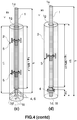
- Figure 4 illustrates various embodiments of a lance according to the present invention. It comprises an inner tube (1), which is hollow and made of metal, generally steel. It extends over a length, L, along a longitudinal direction, X1, from an inlet end (1u) to a tube end (1d), defining a fluid flow path from the tube inlet (1u) to a gas outlet (1t) located at or adjacent to the tube end (1d).
- gas outlet is used herein regardless of the nature of the fluid being injected therethrough, whether a fluid or solid particulate material (e.g., gas alone, a mixture of a gas or liquid with solid particles, or a mixture of gas and liquid droplets).
- the length, L can be of the order of several meters, typically 0.5 to 10 m, but more generally from 4 to 7 m, and even about 5 to 6 m long.
- the inner tube is generally albeit not necessarily cylindrical.
- the outlet (1t) can be coaxial with the longitudinal axis, X1, and may correspond to the tube end (1d), but often the outlet (1t) is composed of one or more smaller channels or tubes (6) extending, not necessarily parallel to X1, from -or adjacent to- said tube end (1d), as discussed e.g., in EP-A1-0802262 .
- the inner tube (1) is partially embedded in a refractory sheath (2) made of a refractory material surrounding the inner tube (1) from the tube end (1d) over a length, L1 ⁇ L, of the inner tube.
- the refractory sheath (2) protects the inner tube (1) from any contact with molten metal which would inevitably degrade the inner tube due to the high temperature of the molten metal. It acts as an insulating sleeve. Crack formation in the refractory sheath must be prevented as the formation of cracks is detrimental to the insulating function of the sheath. If a crack propagates as far as the inner tube, molten metal may penetrate and contact the inner tube, thus forming a thermal bridge and corresponding high temperature region in the inner tube, which would rapidly degrade the inner tube.
- a lance is usually held in substantially vertical operating position with holding means (22) (visible in Fig.1(a) ) gripping a portion of the inner tube jutting out of the refractory sheath.
- holding means (22) visible in Fig.1(a)
- the several meters long refractory sheath therefore hangs freely over a metallurgical vessel. It must therefore be secured to prevent the refractory sheath from slipping off the inner tube and falling into the molten metal.
- an anchoring point (4) is rigidly coupled to said inner tube at an anchor level, and is at least partially embedded in the refractory sheath, to prevent any movement of the inner tube at the anchor level relative to the refractory sheath in the longitudinal direction, X1.
- the anchoring level can be located anywhere along the embedded length of the inner tube, preferably near the tube end or near an upstream portion of the refractory sheath, wherein "upstream” and “downstream” are defined with respect of the fluid flow.
- the outlet (1t) does not correspond to the tube end (1d).
- the outlet (1t) is then provided at an end of one or more outlet tubes (6) coupled to and extending from the inner tube, through the refractory sheath to an outer surface of the refractory sheath and forming the gas outlet(s) (1t) bringing the inner bore of the inner tube in fluid communication with the exterior of the lance.
- the outlet tube(s) (6) are located at or adjacent to the tube end (1d).
- the expression "adjacent to the tube end” is meant here to mean within 10% of L1 from the tube end, and preferably not further than 50 cm, more preferably not further than 30 cm from the tube end (1d).
- outlet tubes (6) are transverse to the longitudinal axis, X1, and if they are mechanically strong enough, the outlet tubes can act as anchoring points (4) as illustrated in Figure 4(c) . Further examples of outlet tubes or channels which can be used in a lance of the present invention are depicted in EP-A1-0802262 .
- a single anchoring point (4) is preferred.
- Several anchoring points (4) can be used, as illustrated in Figure 4(b) , provided all anchoring points are distributed along the length of the inner tube surrounded by the refractory sheath, such that the coupling locations of the two anchoring points most remote from one another are preferably separated by a distance, L0, smaller than 5.5 10 -6 / ⁇ [m] (L0 ⁇ 5.5 10 -6 / ⁇ [m]), wherein ⁇ is the coefficient of thermal expansion of the inner tube (1).
- the distance, L0, between the two anchoring points most remote from one another measured in the direction of the longitudinal axis, X1, is preferably not greater than 0.5 m (L0 ⁇ 0.5 m).
- the refractory sheath can be safely secured to the inner tube and, at the same time, the thermally induced length variations of the anchoring level are negligible in comparison with the thermally induced length variations over the rest of the inner tube.
- the single anchoring point (4) or the one of several anchoring points located furthest from the inlet end (1u) is preferably coupled to the inner tube at a location at or adjacent to the tube end (1d).
- outlet tubes (6) act as anchoring points (4) discussed supra and illustrated in Figure 4(c) is an example of this embodiment.
- the single anchoring point (4) or the one of several anchoring points located closest to the inlet end (1u) can be located within 50 cm of the upstream end of the refractory sheath.
- the refractory sheath (2) is separated from the inner tube (1) by an annular gap (1g) extending over a length, Lg, which is at least 50% of L1.
- the maximum width of the annular gap (1g) is preferably comprised between 0.5 and 15 mm, more preferably between 1 and 10 mm and most preferably between 2 and 5 mm.
- the annular gap defined by an outer surface of the inner tube and an opposite inner surface of the refractory sheath allows said outer surface of the inner tube to move relative to said inner surface of the refractory sheath without generating substantial shear stresses.
- Lg is at least 60% of the length, L1, of inner tube embedded in (or surrounded by) the refractory sheath (Lg ⁇ 0.6 L1), preferably at least 75% of L1 (Lg ⁇ 3 ⁇ 4 L1).
- embedded is used herein to encompass both the case wherein the inner tube and refractory sheath contact each other forming an interface, and the case wherein they are separated by a gap (1g).
- the annular gap Before firing of the refractory sheath, the annular gap may be filled by a thermally degradable material or thermally removable material.
- This thermally degradable material or thermally removable material will be discussed more in details below with respect to the process for producing a lance according to the present invention. Suffices to say that the thermally degradable material or thermally removable material is removed from the annular gap by degradation, melting, vaporization, combustion or dissolution during firing of the refractory sheath, if it applies, or during use in a metallurgical installation (in some cases the refractory sheath is not fired).
- This geometry as such would, however, be unstable because in use the long portion of tube un-coupled to the refractory sheath (i.e., excluding the anchor level) would vibrate and hit the refractory wall defining the annular gap (1g), thus causing cracks in the refractory material.
- annular guide (5) surrounding the inner tube and located within the length, Lg, of the annular gap (1g).
- Figures 5 to 7 illustrate embodiments of such annular guides which comprise:
- the annular guide (5) is characterized in that said at least two anchor protrusions are distributed over the external surface of the annular portion (5A), separated from one another by an angle comprised between 90° and 270° measured from the centroid of the annular portion and between the contact points of the two anchor protrusions (5P) with the outer surface of the annular portion (5A) of the annular guide.
- a first and second protrusions (5P1, 5P3) can be separated by an angle smaller than 90° provided there is at least a third protrusion (5P2) which forms with the first protrusion (5P1) an angle comprised between 90 and 270°.
- the anchor protrusions (5P) also contribute to the reinforcement of the refractory material forming the sheath.
- at least three anchor protrusions per annular guide are preferred.
- the anchor protrusions can have different geometries, as long as they protrude out of the outer surface of the annular portion (5A) of the annular guide, and can thus be embedded in the refractory material of the sheath.
- the anchor protrusions (5P) generally comprise two portions transverse to each other, preferably defining a T-shape (cf. Figure 5 ), V-shape (cf. Figure 6(a) ), Y-shape (cf. Figure 6(b) ), X-shape (not shown), L-shaped (not shown), and the like.
- the distribution of the at least two anchor protrusions (5P) over the circumference of the outer surface of the annular portion of the annular guide ensures the stability of annular guide with respect to the parallelism of the annular portion (5A) with respect to the longitudinal axis, X1.
- the inner tube (1) can move freely through the annular portion (5A) and with respect to the refractory sheath at the level of said annular guide.
- the annular guide is provided with two anchor protrusions (5P) separated from one another by an angle comprised between 90 and 270° (cf. Figure 7(a) ), preferably comprised between 120 and 240°, more preferably by an angle of 180° (i.e., the two protrusions are diametrically opposed).
- the annular guide can be provided with three anchor protrusions as illustrated in Figures 5 and 7(a) . It can be provided with four anchor protrusions (5P) as illustrated in Figure 6 . More anchor protrusions may be used, but good results can already be obtained with 2 to 4 anchor protrusions per annular guide (5).
- N of anchor protrusions (5P)
- a distribution of the anchor protrusions (5P) around the perimeter of the annular portion of the annular guides as defined above gives the annular guides a great stability during use, ensuring that they remain substantial co-axial with the inner tube (1).
- a guide gap (5g) is provided between the inner tube and the annular portion (5A) of the annular guides (5).
- the guide gap (5g) must be present between at least 50% of the inner surface of the annular portion and an outer surface of the inner tube.
- the guide gap (5g) extends over the whole perimeter of the annular portion (5A) and inner tube (1).
- the guide gap (5g) ensures that the inner tube can move freely with respect to the annular guide along the longitudinal direction, X1, without generating substantial shear stresses in the refractory material.
- the maximum width of the guide gap (5g) is preferably smaller than the maximum width of the annular gap (1g).
- the maximum width of the guide gap (5g) is preferably comprised between 0.5 and 10 mm, more preferably between 1 and 5 mm.
- the annular portion of the annular guide (5) can form a closed loop.
- the annular portion of the annular guide (5) can form an open loop with a slit (5S) of width of not more than 40% of a perimeter of the annular portion (5A).
- An annular portion (5A) with a slit (5S) has the advantage that the diameter defined by the annular portion may be increased by opening further the width of the slit upon positioning the annular guides over the inner tube (1).
- Most inner tubes are cylindrical (or at least comprise cylindrical portions).
- the inner surface of the annular portion (5A) should define substantially the same cross-section as the inner tube, with dimensions increased to afford the guide gap (5g).
- the annular portion (5A) generally has a height measured along the direction of the longitudinal axis, X1, which is larger than a thickness measured in the radial direction.
- an annular portion can be comprised between 1.5 and 25 cm, preferably between 5 and 20 cm, more preferably between 7 and 15 cm.
- the inner surface of the annular portion (5A) is defined by a vector parallel to the longitudinal axis, X1, as illustrated in Figure 10(a) .
- the inner surface of the annular portion can be curved in the direction of the longitudinal axis, X1. This embodiment can help reducing the frictions between inner tube and annular guide in case the latter is misaligned with respect to the longitudinal axis, X1.
- the inner surface of the annular portion (5A) can be provided with at least two, preferably three (or more) centering elements (5C) illustrated in Figure 11 , protruding radially towards the center of the annular portion and distributed at regular intervals around the perimeter of the inner surface.
- the centering elements (5C) preferably have a curved surface. They may protrude out of the inner surface to a distance corresponding to the width of the annular gap (5g). This way, as illustrated in Figure 11(b) the annular guide maintains a finite number of punctual contacts with the inner tube (1) (three punctual contacts are shown in Figure 11(b) ). This has two advantages.
- the width of the annular gap (5g) can be controlled accurately and there is no risk of misalignment between the annular guide and the inner tube provoked (i.e., annular guides remain co-axial with the longitudinal axis, X1), for example, during casting of the refractory material into a casting mould around the inner tube provided with annular guides (cf. e.g., Figures 8(a) and 9(a) ).
- the inner tube (1) is prevented from vibrating with an amplitude equal to twice the width of the annular gap (5g), yielding a much more stable lance during injection operations.
- the inner tube is free to vary dimensions as a function of temperature with no hindrance from the annular guides.
- the centering elements (5C) are mounted on resilient means or are made of a resilient material to afford radial expansion of the inner tube.
- annular guide (5) located at a distance, preferably of at least L1 / 2, from the anchoring level, as illustrated in Figure 4(d) . It is, however, preferred that at least two annular guides (5) are distributed along the length, Lg, of the annular gap (1g), as illustrated in Figure 4(c) . More annular guides (5) yield higher stability of the inner tube over the length, Lg, wherein the portion of refractory sheath comprises the annular gap (1g).
- a lance according to the present invention can be produced by a process comprising the following steps, illustrated in Figure 8 :
- a sheet (15) of thermally degradable or a thermally removable sheet material between the inner surface of the annular portion of the annular guides (5) and the outer surface of the inner tube.
- the sheet (15) allows the centering of the annular portion with respect to the inner tube (1), co-axially with the longitudinal axis, X1.
- a guide gap (5g) of controlled and substantially constant width throughout the perimeter of the annular portion can thus be obtained.
- the outer surface of the annular portion (5A) and/or some portions of the anchor protrusions (5P) most prompt to create stresses in the surrounding refractory material due to thermal expansion can also be covered with a layer of thermally degradable or thermally removable sheet material (15).
- This process has the advantage that the width of the guide gap (5g) can be controlled independently of the width of the annular gap (1g). It is preferred that the guide gap (5g) be smaller than the annular gap (1g); so that the annular guides (5) restrict the radial movements of the inner tube but not the longitudinal movements. Another advantage of this process is that by resting on the upper edge of a tubular spacer, an annular guide (5) is maintained in good alignment with the longitudinal axis, X1, although the production process of the lance.
- the thermally degradable or thermally removable sheet material can be any material that is combusted at temperatures of the order of 600-1000°C. It may consist of paper or cardboard, a polymer sheet, and the like. The sheet material can also be melted or vaporized at such temperatures. For example a wax or low melting temperature thermoplastic material can be used, such as a polyolefin.
- the mechanically degradable material can be any brittle material that will lose mechanical coherence upon application of a shear stress, in particular provoked by the differing thermal variations between the inner tube (1) and the refractory sheath (2) upon exposure to temperature variations during use of the lance.
- a lance according to the present invention can be produced with the following steps:
- the thermally degradable or thermally removable sheet material (11W) is preferably compressible in thickness,
- a corrugated cardboard sheet material can be used or, alternatively a synthetic foam material.
- annular guides (5) with an open loop shaped annular portion, such that the slit (5S) can be increased by application of a circumferential stress when inserting the annular portion through the inner tube wrapped with the compressible sheet material (11W) to increase the breadth of the opening of the annular portion.
- the annular portion Upon releasing the stress, the annular portion returns to its nominal diameter which is smaller than the diameter of the inner tube wrapped with the sheet material (11W), such that the compressible sheet material is compressed by the annular portion (5A).
- a guide gap (5g) of width smaller than the width of the annular gap (1g) can thus be obtained.
- the refractory material after drying, the refractory material can be fired, All refractory materials do not require firing, but many do.
- the refractory material is sintered and at the same time, the thermally degradable material or thermally removable material of the tubular spacers (11.1, 11.2, 11.n) or of the sheet material (11W) is thermally degraded or removed and at least partially disappears from the outer surface of the inner tube, thus forming:
- the refractory cement is shown in Figures 8 &9 to be cast from the top into a casting mould (12) held vertically. This is indeed a preferred embodiment. It is, however, possible to cast the refractory material into a casting mould held horizontally as described in EP2712938 . As known in the art, the casting mould can be vibrated during casting and setting of the refractory material.
- a lance for injecting a fluid with or without a solid particulate material into a metallurgical vessel filled with molten metal has a substantially longer service life than henceforth achievable.
- the shear stresses mainly due to thermal dilatation mismatches between the metal inner tube and refractory sheath are avoided, thus maintaining the refractory material integrity for a longer time, which can thus protect the inner tube.
- Figure 12 illustrates a lance comprising a pusher (23) and a blocking element (24).
- the pusher (23) e.g. a steel plate which is maintained on the upper surface of the refractory sheath by resilient elements such as pre-stressed springs (25) set between the pusher (23) and the blocking element (24) e.g. a steel plate welded on the inner tube (1).
- the blocking element (24) shifts vertically with the inner tube.
Landscapes
- Engineering & Computer Science (AREA)
- Chemical & Material Sciences (AREA)
- Mechanical Engineering (AREA)
- General Engineering & Computer Science (AREA)
- Manufacturing & Machinery (AREA)
- Materials Engineering (AREA)
- Metallurgy (AREA)
- Organic Chemistry (AREA)
- Treatment Of Steel In Its Molten State (AREA)
- Furnace Charging Or Discharging (AREA)
Description
- The present invention concerns a lance for injecting a fluid or solid particulate material into a metallurgical vessel suitable for the refining process of metals production such as pig iron, steel, or ferronickel. In particular, it concerns a lance having a specific design yielding a higher resistance to cracks formation caused by thermal gradients. The present invention also concerns a process for producing such lance.
- Metal production often requires injection of a fluid, generally a gas with or without solid particulate material, for example for refining process of pig iron and steel production. As illustrated in
Figure 1 , an elongated lance is used to this purpose, with one end dipped in a molten metal (21) contained in a metallurgical vessel (20). A lance is generally composed of a hollow inner tube (1) made of metal, generally steel, and partly embedded in a sheath (2) of refractory material protecting the inner tube from contact with the hot molten metal the lance is dipped in. Because the lance is often dipped substantially vertically into the molten metal, the inner tube is anchored to the sleeve in order to prevent the latter from slipping off the inner tube. For example,Figures 2 &3 ofEP-A1-2712938 illustrate anchoring elements distributed all along the inner tube length. - As illustrated in
Figure 2 , in use a lance is exposed to severe time dependent thermal gradients in a radial direction between the inner tube mean temperature, T1, and the refractory sheath mean temperature T2. For example, when at time, t0, a lance is dipped into a molten metal, the whole lance passes from ambient temperature, TR, (or pre-heated temperature) outside the molten metal to the temperature, TM, of the molten metal at the outer surface of the refractory sheath, while the inner tube remains at a relatively low temperature, cooled by the fluid flowing therethrough. During the injection process, the flow rate and composition of the fluid and particles being injected through the inner tube may vary with time, depending on the pre-set injection sequence. The temperature of the inner tube will vary accordingly. Referring toFigure 2 , if the flow rate in the inner tube decreases between times t1 and t2, the inner tube temperature, T1, will increase and, inversely, if the flow rate increases between times t3 and t4, or the composition of the fluid is varied yielding a higher thermal conductivity, the temperature, T1, of the inner tube will decrease accordingly, with further variations of the thermal gradient, ΔT = T2 - T1, during use; the value of ΔT can reach the order of 1000°C! When the lance is withdrawn from the metallurgical vessel at time, t5, the gas flow is generally interrupted and the inner tube temperature, T1, increases before gradually dropping together with T2 to room temperature. - The coefficient of thermal expansion of steel can be about two orders of magnitude higher than the thermal expansion coefficient of refractory materials usually used for manufacturing such lances. The difference in coefficients of thermal expansion and the variation of strong temperature gradients generate substantial differences in thermal expansions between the steel inner tube and the refractory sheath material. Since no relative movement between the inner tube and outer refractory sheath is possible at the level of the anchoring elements, substantial shear stresses between the inner tube and the refractory sheath material are created during use. As a consequence, cracks are formed in the refractory material as illustrated in
Figure 3 , which shows a degradation sequence with time of the refractory sheath during use. When the cracks give the molten metal access to the inner tube, the lance is definitely out of use. - In order to decrease the cracks in the refractory sheath,
DE-U1-29705901 proposes a lance made of a thin inner metal tube in close contact with the refractory sheath reinforced by anchor nodes and a metal rod of a smaller diameter than the inner tube, the rod being centered inside the interior space of the inner metal tube and is welded to the inner metal tube through four protrusions close to the lower end of the metal tube. The rigidity of the lance is conferred by the metal rod. Argon is flushed in the cavity created between the inner tube and the metal rod. As the thickness of the inner tube wall is small, the flushing of the gas cools down the wall and prevents to a certain extent the inner tube from expanding axially. The results are however unsatisfactory because the inner tube is still in close contact with the refractory sheath. - An alternative coupling of the inner tube to the refractory sheath is proposed in
GB-A-2107034 EP-A1-2712938 cited supra. An outlet end of the inner tube is provided with anchoring hooks welded around the circumference of the inner tube. The anchoring hooks are embedded in the refractory sheath and prevent the refractory sheath from sliding out of the inner tube. A number of individual (single) coil steel springs are distributed along the rest of the embedded portion of the inner tube to stabilize the inner tube inside the refractory sheath. Whilst the anchoring hooks are fixedly attached to the tube, the coil steel springs afford axial movement of the tube relative to the coil springs. The coils of the springs are a close fit on the inner tube so that they grip the tube which is thus maintained in its axial position. Radially extending members are provided by the free ends of each spring coil and are embedded in the refractory material of the sheath. They can act as levers to assist in splaying the turns of a coil and thus enable a spring to be moved freely into position along the length of the tube and, upon release, the coil is retracted and the spring firmly grips the inner tube. - In a preferred embodiment of the lance disclosed in
GB-A-2107034 - The concept proposed in
GB-A-2107034 DE29705901 U1 of providing an inner tube with fixed anchors located solely at the outlet end of the inner tube, and a series of sliding anchors distributed over the remaining length of the inner tube is theoretically interesting as it allows the steel of the inner tube and the refractory material of the sheath to expand relatively freely from one another in response to temperature gradient variations, without building up any substantial shear stresses. The reduction to practice of said concept as disclosed in the aforementioned art, however, is far from satisfactory for the following reasons. The coils of the springs are already close fit on the inner tube before casting the refractory material of the sheath. When the refractory sheath is formed and set, the coil springs are embedded in said refractory material and the extending members thereof cannot move anymore to splay the coil of the spring. Upon use, the temperature, T1, of the inner tube and coil springs will raise and will thus expand radially. The coil springs, on the other hand cannot expand more than allowed by their being embedded in the refractory material. It follows that the grip of the coil springs on the inner tube becomes so tight that in practice no movement of the inner tube is possible anymore with respect to the refractory sheath. Consequently substantial shear stresses build up as in traditional lances, leading to early crack formation. - There therefore remains a need for a lance for injecting a fluid into a metallurgical vessel which is more resistant to crack formation than henceforth achieved. The present invention proposes a solution to this problem with a novel and original concept of lance design. These and other advantages of the present invention are described with more details in the following.
- The present invention is defined in the attached independent claims. Preferred embodiments are defined in the dependent claims. In particular, the present invention concerns a lance for top injection of a fluid or particulate material in metallurgical vessels, wherein the lance comprises:
- (a) an inner tube, which is hollow and made of metal, and extending over a length, L, along a longitudinal direction, X1, from an inlet end to a tube end, defining a fluid flow path from the tube inlet to a gas outlet located at or adjacent to the tube end,
- (b) a sheath of refractory material surrounding the inner tube from the tube end over a length, L1 ≤ L, of the inner tube,
- (c) an anchoring point rigidly coupled to said inner tube at an anchor level, and at least partially embedded in the refractory sheath, preventing any movement of the inner tube at the anchor level relative to the refractory sheath in the longitudinal direction, X1,
- (d) an annular gap separating the inner tube from the refractory sheath over a length, Lg, which is at least 50% of L1;
- (e) at least one annular guide surrounding the inner tube and located within the length, Lg, of the annular gap, said annular guide comprising:
- an annular portion having an inner surface and an outer surface, the inner surface facing and circumscribing the inner tube, and
- at least two anchor protrusions rigidly extending transversally from the outer surface of the annular portion and at least partially embedded in the refractory sheath, wherein a guide gap is formed between at least 50% of the inner surface of the annular portion and an outer surface of the inner tube allowing the movement of the inner tube with respect to the annular guide along the longitudinal direction, X1
- In some cases, a thermally degradable material, mechanically removable material, and/or thermally removable material can be present in the annular gap. This is the case if the lance has not been exposed to high temperatures or mechanical stresses sufficient to remove all such materials from around the inner tube. For example if a lance has not been fired and has not been used in a metallurgical vessel, the whole volume of the annular gap will be filled with such material. Alternatively, after use of a lance, temperature conditions may not have been sufficient to remove the whole of said materials, leaving some fragments in the annular gap. The same may apply to the outer surface of the annular portion and/or some portions of the anchor protrusions which may be at least partially covered with a layer of thermally degradable or thermally removable sheet material.
- In a preferred embodiment, the maximum width of the annular gap is comprised between 0.5 and 15 mm, preferably between 1 and 10 mm and more preferably between 2 and 5 mm. It is preferred that the annular gap be homogeneous over the whole circumference of the inner tube, and such result is generally achieved with production methods as described below. But since the inner tube may move in the radial direction within the space defining the annular gap, it cannot be assured that the inner tube will always remain co-axial with the annular gap. In order to restrict the freedom of movement of the inner tube within the annular gap, annular guides can be used. To fulfil this function, it is preferred that the guide gap defined between the inner surface of the annular portion of an annular guide and the outer surface of the inner tube be smaller than or equal to the annular gap. More preferably, the maximum width of the guide gap is smaller than the maximum width of the annular gap and is preferably comprised between 0.5 and 10 mm, more preferably between 1 and 5 mm.
- In one embodiment, the annular portion of the annular guide forms a closed loop. In an alternative embodiment, the annular portion of the annular guide forms an open loop with a slit of width of not more than 40% of an inner perimeter of the annular portion. The latter embodiment can be advantageous in that it requires less material, and in that the inner diameter of the annular portion can be resiliently varied by increasing or decreasing the width of the slit.
- In many lances, it is preferred that an outlet portion of the inner tube adjacent to and including the tube end is coupled to one or more outlet tubes extending from the inner tube, through the refractory sheath to the gas outlet(s) bringing an inner bore of the inner tube in fluid communication with the exterior of the lance. This design allows to orient the flow(s) of gas and/or particles in different directions, and reduces exposure of the inner tube to the high temperatures of the metallurgical vessel.
- It is preferred that a single anchoring point is coupled to said inner tube, to give freedom to most of the embedded length of the inner tube to move longitudinally with respect to the refractory sheath when exposed to temperature gradients. In case several anchoring points are distributed along the length of the inner tube surrounded by the refractory sheath, it is necessary that the coupling locations to the inner tube of the two anchoring points most remote from one another in the longitudinal direction, X1, are separated by a distance, L0, wherein L0 ≤ 5.5 10-6 / α [m], wherein α is the coefficient of thermal expansion of the inner tube. In all cases it is necessary that the distance, L0, is in any case not greater than 50 cm.
- In a preferred design of the lance, the single anchoring point or the one of several anchoring points located furthest from the inlet end is coupled to the inner tube at a location at or adjacent to the tube end. This configuration is advantageous for the following reasons. It is well known that refractory materials have better resistance in compression than in tensile mode. Since the lance is generally held in working position by clamping a top portion of the inner tube jutting out of the refractory sheath, in use the weight of the refractory sheath located upstream from the anchor point rests on the anchoring point and is being compressed The portion of refractory exposed to tensile stresses is the portion extending downstream from the anchoring point. By locating the anchoring point near the tube end of the inner tube, most of the refractory material is located upstream from the anchoring point and is compressed, whilst the portion of refractory material located downstream of the anchoring point, exposed to tensile stresses generated by its own weight is substantially smaller (and lighter).
- The anchor protrusions may comprise two portions transverse to each other. For example they can define a T-shape, V-shape, X-shape, or Y-shape in order to create a strong anchor in the refractory sheath.
- The present invention also concerns a process for manufacturing a lance as defined above, comprising the following steps:
- (a) Providing an inner tube of length L, defined by an outer surface and comprising a tube end and an anchoring point rigidly coupled to said outer surface positioned at a distance, La , from the tube end, with La ≤ L;
- (b) Inserting a first tubular spacer made of a thermally degradable material, a mechanically removable material, and/or a thermally removable material over the inner tube;
- (c) Inserting an annular guide having at least two anchoring protrusions over the inner tube until it rests on an edge of the first tubular spacer,
- (d) Repeating steps (b) and (c) until the desired number of annular guides is reached and until the cumulated length of tubular spacers and annular guides equals or is greater than the desired length, Lg, of the annular gap;
- (e) Providing a casting mould having a length greater than or equal to L1
- (f) Positioning the thus formed inner tube into said mould with the tube end within said mould,
- (g) Casting a refractory material into the mould embedding the thus formed inner tube and at least a portion of the anchoring protrusions of the annular guides, thus forming a sheath of refractory material of length, L1 wherein Lg ≥ ½ L1 ;
- (h) Drying at least partially the refractory material.
- A lance as defined above can also be produced by an alternative process comprising the following steps:
- (a) Providing an inner tube (1) of length L, defined by an outer surface and comprising an outlet end (1d) and an anchoring point (4) rigidly coupled the said outer surface and comprised within a distance L1 from the outlet end (1d), with L1 ≤ L;
- (b) Wrapping the outer surface of the inner tube (1) with a thermally degradable , a mechanically removable material, and/or thermally removable sheet material (11W) of given thickness over a length, Lg, equal to at least 50% of the distance, L1;
- (c) Inserting over the sheet wrapped inner tube (1) as many annular guides (5) as desired and spaced apart from one another by a pre-defined distance;
- (d) Providing a casting mould of length greater or equal to L1
- (e) Positioning the thus wrapped inner tube into said mould with the outlet end within said mould,
- (f) Casting the refractory material into the mould embedding the thus formed inner tube and at least a portion of the anchoring protrusions (5P) of the annular guides, thus forming a sheath of refractory material of length, L1;
- (g) Drying at least partially the refractory material.
- The thermally degradable material or thermally removable material of the tubular spacers or of the sheet material can be thermally degraded or removed and at least partially disappears from the outer surface of the inner tube during either firing of the lance or upon dipping the lance into a metallurgical vessel, such that,:
- an annular gap is formed between the inner tube and the refractory sheath over a length, Lg, at least equal to 50% of the length, L1, of the refractory sheath allowing the movement along the longitudinal direction, X1, of a portion of the inner tube remote from the anchoring point (4), with respect to the refractory sheath ,and
- a guide gap is formed over at least 50% of a perimeter of the inner surface of the annular guides allowing the movement of the inner tube with respect to the annular guides along the longitudinal direction, X1.
- Either of the two processes defined above may further comprise a step of applying thermally degradable or thermally removable sheet material onto at least a portion of said at least two anchor protrusions and/or of the outer surface of said annular portion of the annular guides. Removal of this material forms a gap allowing for some radial expansion of the annular portion of the annular guides.
- In addition to the cracks due to thermal cycles and different expansion coefficients of the refractory sheath and of the inner tube, small cracks resulting from clumsy handling during transportation can occur. Cracks can also be created in the area of the bath level of the molten metal: as the gas flushes in the molten metal bath, the bubbles rise along the lance and burst at the surface of the molten metal bath creating a turbulence. High mechanical forces are generated due to the splashing molten metal, creating new cracks or increasing the size of the existing cracks by the infiltration of molten metal. Sometimes, the radial cracks are very deep and result in the splitting of the refractory sheath into two parts. As the density of the refractory sheath is lower than the density of molten metal, the detached upper part of the sheath floats up as there is no more connection with the inner tube. The inner tube is then no longer protected and enters in contact with the molten metal and eventually melts down. The lower part of the lance is lost in the bath.
- In order to prevent any split of the lance in such a case, an advantageous embodiment of the invention comprises a pusher and a blocking element. The blocking element is rigidly coupled to the inner tube in a portion of said inner tube at a distance from the anchor level greater than L1 and the pusher is elastically attached to the blocking element, the pusher being adapted to push the refractory sheath along the direction of the longitudinal axis X1. In another embodiment, the pusher comprises a contact element adapted to contact the surface of the refractory sheath opposite to the anchor level and is attached to the blocking element by one or more resilient elements.
-
-
Figure 1 illustrates a lance (a) before introduction into a metallurgical vessel, and (b) after introduction and during injection of a fluid with or without solid particulate material. -
Figure 2 illustrates schematically the mean temperature, T1, of the inner tube and, T2, of the refractory sheath (top graph) and the corresponding temperature gradient, ΔT = T2 - T1, (bottom graph) as a function of utilization time. In both graphs, the abscissa represents the time. -
Figure 3 schematically illustrates a degradation sequence of a lance of the prior art during use. -
Figure 4 : illustrates four embodiments of lances according to the present invention. -
Figure 5 : illustrates various embodiments of annular guides suitable for the present invention. -
Figure 6 : illustrates alternative embodiments of annular guides suitable for the present invention. -
Figure 7 : illustrates various positioning of the anchor protrusions about the outer surface of the annular portion of an annular guide. -
Figure 8 : illustrates a first embodiment for the production of a lance according to the present invention. -
Figure 9 : illustrates a second embodiment for the production of a lance according to the present invention. -
Figure 10 : illustrates a cross-section of an annular guide according to two embodiments of the present invention. -
Figure 11 : illustrates a preferred embodiment of annular guide provide with centering elements. -
Figure 12 : illustrates a preferred embodiment comprising a pusher and a blocking element. -
Figure 4 illustrates various embodiments of a lance according to the present invention. It comprises an inner tube (1), which is hollow and made of metal, generally steel. It extends over a length, L, along a longitudinal direction, X1, from an inlet end (1u) to a tube end (1d), defining a fluid flow path from the tube inlet (1u) to a gas outlet (1t) located at or adjacent to the tube end (1d). The term "gas outlet" is used herein regardless of the nature of the fluid being injected therethrough, whether a fluid or solid particulate material (e.g., gas alone, a mixture of a gas or liquid with solid particles, or a mixture of gas and liquid droplets). The length, L, can be of the order of several meters, typically 0.5 to 10 m, but more generally from 4 to 7 m, and even about 5 to 6 m long. The inner tube is generally albeit not necessarily cylindrical. The outlet (1t) can be coaxial with the longitudinal axis, X1, and may correspond to the tube end (1d), but often the outlet (1t) is composed of one or more smaller channels or tubes (6) extending, not necessarily parallel to X1, from -or adjacent to- said tube end (1d), as discussed e.g., inEP-A1-0802262 . - The inner tube (1) is partially embedded in a refractory sheath (2) made of a refractory material surrounding the inner tube (1) from the tube end (1d) over a length, L1 ≤ L, of the inner tube. In use, the refractory sheath (2) protects the inner tube (1) from any contact with molten metal which would inevitably degrade the inner tube due to the high temperature of the molten metal. It acts as an insulating sleeve. Crack formation in the refractory sheath must be prevented as the formation of cracks is detrimental to the insulating function of the sheath. If a crack propagates as far as the inner tube, molten metal may penetrate and contact the inner tube, thus forming a thermal bridge and corresponding high temperature region in the inner tube, which would rapidly degrade the inner tube.
- A lance is usually held in substantially vertical operating position with holding means (22) (visible in
Fig.1(a) ) gripping a portion of the inner tube jutting out of the refractory sheath. The several meters long refractory sheath therefore hangs freely over a metallurgical vessel. It must therefore be secured to prevent the refractory sheath from slipping off the inner tube and falling into the molten metal. For this reason an anchoring point (4) is rigidly coupled to said inner tube at an anchor level, and is at least partially embedded in the refractory sheath, to prevent any movement of the inner tube at the anchor level relative to the refractory sheath in the longitudinal direction, X1. In case the outlet (1t) is coaxial with the longitudinal axis and corresponds to the tube end (1d) (cf.Figure 4(d) ), the anchoring level can be located anywhere along the embedded length of the inner tube, preferably near the tube end or near an upstream portion of the refractory sheath, wherein "upstream" and "downstream" are defined with respect of the fluid flow. - Often, the outlet (1t) does not correspond to the tube end (1d). The outlet (1t) is then provided at an end of one or more outlet tubes (6) coupled to and extending from the inner tube, through the refractory sheath to an outer surface of the refractory sheath and forming the gas outlet(s) (1t) bringing the inner bore of the inner tube in fluid communication with the exterior of the lance. The outlet tube(s) (6) are located at or adjacent to the tube end (1d). The expression "adjacent to the tube end" is meant here to mean within 10% of L1 from the tube end, and preferably not further than 50 cm, more preferably not further than 30 cm from the tube end (1d). If more than one outlet tubes (6) are transverse to the longitudinal axis, X1, and if they are mechanically strong enough, the outlet tubes can act as anchoring points (4) as illustrated in
Figure 4(c) . Further examples of outlet tubes or channels which can be used in a lance of the present invention are depicted inEP-A1-0802262 . - A single anchoring point (4) is preferred. Several anchoring points (4) can be used, as illustrated in
Figure 4(b) , provided all anchoring points are distributed along the length of the inner tube surrounded by the refractory sheath, such that the coupling locations of the two anchoring points most remote from one another are preferably separated by a distance, L0, smaller than 5.5 10-6 / α [m] (L0 ≤ 5.5 10-6 / α [m]), wherein α is the coefficient of thermal expansion of the inner tube (1). For example, considering a coefficient of thermal expansion of a steel inner tube of α (steel) = 1.0-1.3 10-5 K-1 ⇒ L0 ≤ 5.5 10-6 m K-1 / (1 to 1.3 10-5 K-1)
= 0.42-0.5 m. The distance, L0, between the two anchoring points most remote from one another measured in the direction of the longitudinal axis, X1, is preferably not greater than 0.5 m (L0 ≤ 0.5 m). With such constraint on the length, L0, of the anchoring level, the refractory sheath can be safely secured to the inner tube and, at the same time, the thermally induced length variations of the anchoring level are negligible in comparison with the thermally induced length variations over the rest of the inner tube. - The single anchoring point (4) or the one of several anchoring points located furthest from the inlet end (1u) is preferably coupled to the inner tube at a location at or adjacent to the tube end (1d). The case wherein outlet tubes (6) act as anchoring points (4) discussed supra and illustrated in
Figure 4(c) is an example of this embodiment. Alternatively, the single anchoring point (4) or the one of several anchoring points located closest to the inlet end (1u) can be located within 50 cm of the upstream end of the refractory sheath. - The refractory sheath (2) is separated from the inner tube (1) by an annular gap (1g) extending over a length, Lg, which is at least 50% of L1. The maximum width of the annular gap (1g) is preferably comprised between 0.5 and 15 mm, more preferably between 1 and 10 mm and most preferably between 2 and 5 mm. The annular gap defined by an outer surface of the inner tube and an opposite inner surface of the refractory sheath, allows said outer surface of the inner tube to move relative to said inner surface of the refractory sheath without generating substantial shear stresses. It follows that it is advantageous to have a gap length, Lg, as long as possible, to reduce the portion of contact between the inner tube and refractory sheath forming an interface in portions of the lance exposed to high thermal gradients. For example, it is preferred that Lg is at least 60% of the length, L1, of inner tube embedded in (or surrounded by) the refractory sheath (Lg ≥ 0.6 L1), preferably at least 75% of L1 (Lg ≥ ¾ L1). It should be noted that the term "embedded" is used herein to encompass both the case wherein the inner tube and refractory sheath contact each other forming an interface, and the case wherein they are separated by a gap (1g).
- Before firing of the refractory sheath, the annular gap may be filled by a thermally degradable material or thermally removable material. This thermally degradable material or thermally removable material will be discussed more in details below with respect to the process for producing a lance according to the present invention. Suffices to say that the thermally degradable material or thermally removable material is removed from the annular gap by degradation, melting, vaporization, combustion or dissolution during firing of the refractory sheath, if it applies, or during use in a metallurgical installation (in some cases the refractory sheath is not fired). Even after firing or use, some scraps of said thermally degradable material or thermally removable material may still remain in the annular gap, but at least 80% of the volume of the annular gap should preferably be free of such material during use, in order for a lance according to the present invention to reach its full potential.
- The annular gap (1g) together with anchoring points concentrated solely at a single anchor level of length, L0, as discussed above, along the length of the inner tube, allows a movement of the inner tube relative to the refractory sheath over the whole length thereof excluding the anchor level. This geometry as such would, however, be unstable because in use the long portion of tube un-coupled to the refractory sheath (i.e., excluding the anchor level) would vibrate and hit the refractory wall defining the annular gap (1g), thus causing cracks in the refractory material.
- In order to stabilize the lance, it must comprise at least one annular guide (5) surrounding the inner tube and located within the length, Lg, of the annular gap (1g).
Figures 5 to 7 illustrate embodiments of such annular guides which comprise: - an annular portion (5A) having an inner surface and an outer surface, the inner surface facing and circumscribing the inner tube, and
- at least two anchor protrusions (5P) rigidly extending transversally from the outer surface of the annular portion and at least partially embedded in the refractory sheath (2),
- As shown in
Figure 7 , the annular guide (5) is characterized in that said at least two anchor protrusions are distributed over the external surface of the annular portion (5A), separated from one another by an angle comprised between 90° and 270° measured from the centroid of the annular portion and between the contact points of the two anchor protrusions (5P) with the outer surface of the annular portion (5A) of the annular guide. As shown inFigure 7(b) , a first and second protrusions (5P1, 5P3) can be separated by an angle smaller than 90° provided there is at least a third protrusion (5P2) which forms with the first protrusion (5P1) an angle comprised between 90 and 270°. Besides anchoring the annular guide as discussed supra, the anchor protrusions (5P) also contribute to the reinforcement of the refractory material forming the sheath. For reinforcement purposes and for homogeneous stress distribution, at least three anchor protrusions per annular guide are preferred. - The anchor protrusions can have different geometries, as long as they protrude out of the outer surface of the annular portion (5A) of the annular guide, and can thus be embedded in the refractory material of the sheath. In particular, the anchor protrusions (5P) generally comprise two portions transverse to each other, preferably defining a T-shape (cf.
Figure 5 ), V-shape (cf.Figure 6(a) ), Y-shape (cf.Figure 6(b) ), X-shape (not shown), L-shaped (not shown), and the like. The distribution of the at least two anchor protrusions (5P) over the circumference of the outer surface of the annular portion of the annular guide ensures the stability of annular guide with respect to the parallelism of the annular portion (5A) with respect to the longitudinal axis, X1. As long as the annular portion (a) remains substantially parallel to, preferably co-axial with the longitudinal axis, X1, the inner tube (1) can move freely through the annular portion (5A) and with respect to the refractory sheath at the level of said annular guide. - In one embodiment the annular guide is provided with two anchor protrusions (5P) separated from one another by an angle comprised between 90 and 270° (cf.
Figure 7(a) ), preferably comprised between 120 and 240°, more preferably by an angle of 180° (i.e., the two protrusions are diametrically opposed). The annular guide can be provided with three anchor protrusions as illustrated inFigures 5 and7(a) . It can be provided with four anchor protrusions (5P) as illustrated inFigure 6 . More anchor protrusions may be used, but good results can already be obtained with 2 to 4 anchor protrusions per annular guide (5). Regardless of the number, N, of anchor protrusions (5P), they can always -albeit not necessarily-- be distributed evenly around the outer surface of the annular portion (5A), each anchor protrusion being separated from the closest neighbor by an angle of 360° / N (i.e., 180° for N = 2 anchor protrusions, 120° for N = 3, 90° for N = 4, and so on). A distribution of the anchor protrusions (5P) around the perimeter of the annular portion of the annular guides as defined above gives the annular guides a great stability during use, ensuring that they remain substantial co-axial with the inner tube (1). This is not the case, for example, with the free ends of the coil springs disclosed inGB-A-2107034 - By contrast with the lance disclosed in
GB-A-2107034 - As illustrated in
Figures 5(a) &(d), 6(a), 7, and 11, the annular portion of the annular guide (5) can form a closed loop. Alternatively, as illustrated inFigures 5(b) &(c) and 6(b), the annular portion of the annular guide (5) can form an open loop with a slit (5S) of width of not more than 40% of a perimeter of the annular portion (5A). An annular portion (5A) with a slit (5S) has the advantage that the diameter defined by the annular portion may be increased by opening further the width of the slit upon positioning the annular guides over the inner tube (1). Most inner tubes are cylindrical (or at least comprise cylindrical portions). In this case, the annular guides (5) should define a substantially cylindrical inner surface of the annular portion of diameter, D5, equal to the outer diameter, D1, of the cylindrical (portion of the) inner tube (1) increased by twice the annular gap width, W5, i.e., D5 = D1 + 2 W5. In case of an inner tube having a non-circular cross-section, the inner surface of the annular portion (5A) should define substantially the same cross-section as the inner tube, with dimensions increased to afford the guide gap (5g). The annular portion (5A) generally has a height measured along the direction of the longitudinal axis, X1, which is larger than a thickness measured in the radial direction. For example the height of an annular portion can be comprised between 1.5 and 25 cm, preferably between 5 and 20 cm, more preferably between 7 and 15 cm. In one embodiment, the inner surface of the annular portion (5A) is defined by a vector parallel to the longitudinal axis, X1, as illustrated inFigure 10(a) . Alternatively, as shown inFigure 10(b) , the inner surface of the annular portion can be curved in the direction of the longitudinal axis, X1. This embodiment can help reducing the frictions between inner tube and annular guide in case the latter is misaligned with respect to the longitudinal axis, X1. - In a preferred embodiment, the inner surface of the annular portion (5A) can be provided with at least two, preferably three (or more) centering elements (5C) illustrated in
Figure 11 , protruding radially towards the center of the annular portion and distributed at regular intervals around the perimeter of the inner surface. The centering elements (5C) preferably have a curved surface. They may protrude out of the inner surface to a distance corresponding to the width of the annular gap (5g). This way, as illustrated inFigure 11(b) the annular guide maintains a finite number of punctual contacts with the inner tube (1) (three punctual contacts are shown inFigure 11(b) ). This has two advantages. First the width of the annular gap (5g) can be controlled accurately and there is no risk of misalignment between the annular guide and the inner tube provoked (i.e., annular guides remain co-axial with the longitudinal axis, X1), for example, during casting of the refractory material into a casting mould around the inner tube provided with annular guides (cf. e.g.,Figures 8(a) and 9(a) ). Second, during use, the inner tube (1) is prevented from vibrating with an amplitude equal to twice the width of the annular gap (5g), yielding a much more stable lance during injection operations. At the same time, since the contact between the centering elements (5C) and the inner tube is purely punctual, the inner tube is free to vary dimensions as a function of temperature with no hindrance from the annular guides. In a preferred embodiment, the centering elements (5C) are mounted on resilient means or are made of a resilient material to afford radial expansion of the inner tube. - There can be as few as a single annular guide (5) located at a distance, preferably of at least L1 / 2, from the anchoring level, as illustrated in
Figure 4(d) . It is, however, preferred that at least two annular guides (5) are distributed along the length, Lg, of the annular gap (1g), as illustrated inFigure 4(c) . More annular guides (5) yield higher stability of the inner tube over the length, Lg, wherein the portion of refractory sheath comprises the annular gap (1g). - A lance according to the present invention can be produced by a process comprising the following steps, illustrated in
Figure 8 : - (a) Providing an inner tube (1) of length L, defined by an outer surface and comprising a tube end (1d) and an anchoring point (4) rigidly coupled to said outer surface positioned at a distance, La , from the tube end (1d), with La ≤ L1;
- (b) Inserting a first tubular spacer (11.1) made of a thermally degradable material, a mechanically removable material, and/or a thermally removable material over the inner tube (1);
- (c) Inserting an annular guide (5) having at least two anchoring protrusions over the inner tube until it rests on an edge of the first tubular spacer (11.1),
- (d) Repeating steps (b) and (c) until the desired number of annular guides is reached and until the cumulated length of tubular spacers and annular guides equals or is greater than the desired length, Lg, of the annular gap (1g);
- (e) Providing a casting mould (12) having a length greater than or equal to L1
- (f) Positioning the thus formed inner tube into said mould with the tube end within said mould,
- (g) Casting a refractory material into the mould embedding the thus formed inner tube and at least a portion of the anchoring protrusions (5P) of the annular guides, thus forming a sheath of refractory material of length, L1 wherein Lg ≥ ½ Ll;
- (h) Drying at least partially the refractory material.
- As shown in
Figure 8(a) it is preferred to additionally provide a sheet (15) of thermally degradable or a thermally removable sheet material between the inner surface of the annular portion of the annular guides (5) and the outer surface of the inner tube. The sheet (15) allows the centering of the annular portion with respect to the inner tube (1), co-axially with the longitudinal axis, X1. A guide gap (5g) of controlled and substantially constant width throughout the perimeter of the annular portion can thus be obtained. Similarly, the outer surface of the annular portion (5A) and/or some portions of the anchor protrusions (5P) most prompt to create stresses in the surrounding refractory material due to thermal expansion can also be covered with a layer of thermally degradable or thermally removable sheet material (15). Upon degradation or removal of the sheet material a gap is thus created to allow said annular portion and said portions of the anchoring protrusions (5P) to freely expand thermally, in particular radially, without creating stresses responsible for the formation of longitudinal cracks in the refractory material. - This process has the advantage that the width of the guide gap (5g) can be controlled independently of the width of the annular gap (1g). It is preferred that the guide gap (5g) be smaller than the annular gap (1g); so that the annular guides (5) restrict the radial movements of the inner tube but not the longitudinal movements. Another advantage of this process is that by resting on the upper edge of a tubular spacer, an annular guide (5) is maintained in good alignment with the longitudinal axis, X1, although the production process of the lance.
- The thermally degradable or thermally removable sheet material can be any material that is combusted at temperatures of the order of 600-1000°C. It may consist of paper or cardboard, a polymer sheet, and the like. The sheet material can also be melted or vaporized at such temperatures. For example a wax or low melting temperature thermoplastic material can be used, such as a polyolefin.
- The mechanically degradable material can be any brittle material that will lose mechanical coherence upon application of a shear stress, in particular provoked by the differing thermal variations between the inner tube (1) and the refractory sheath (2) upon exposure to temperature variations during use of the lance.
- In an alternative process illustrated in
Figure 9 , a lance according to the present invention can be produced with the following steps: - (a) Providing an inner tube (1) of length L, defined by an outer surface and comprising an outlet end (1d) and an anchoring point (4) rigidly coupled the said outer surface and comprised within a distance L1 from the outlet end (1d), with L1 ≤ L;
- (b) Wrapping the outer surface of the inner tube (1) with a thermally degradable or thermally removable sheet material (11W) of given thickness over a length, Lg, equal to at least 50% of the distance, L1,
- (c) Inserting over the sheet wrapped inner tube (1) as many annular guides (5) as desired and spaced apart from one another by a pre-defined distance;
- (d) Providing a casting mould (15) of length greater or equal to L1
- (e) Positioning the thus wrapped inner tube into said mould with the outlet end within said mould,
- (f) Casting the refractory material into the mould embedding the thus formed inner tube and at least a portion of the anchoring protrusions (5P) of the annular guides, thus forming a sheath of refractory material of length, L1;
- (g) Drying at least partially the refractory material.
- The thermally degradable or thermally removable sheet material (11W) is preferably compressible in thickness, For example, a corrugated cardboard sheet material can be used or, alternatively a synthetic foam material. In this embodiment, it is preferred to used annular guides (5) with an open loop shaped annular portion, such that the slit (5S) can be increased by application of a circumferential stress when inserting the annular portion through the inner tube wrapped with the compressible sheet material (11W) to increase the breadth of the opening of the annular portion. Upon releasing the stress, the annular portion returns to its nominal diameter which is smaller than the diameter of the inner tube wrapped with the sheet material (11W), such that the compressible sheet material is compressed by the annular portion (5A). After degradation or removal of the sheet material (11W) a guide gap (5g) of width smaller than the width of the annular gap (1g) can thus be obtained.
- Regardless of which of the two processes described above and illustrated in
Figures 8 &9 is used for producing a lance according to the present invention, after drying, the refractory material can be fired, All refractory materials do not require firing, but many do. During the firing step the refractory material is sintered and at the same time, the thermally degradable material or thermally removable material of the tubular spacers (11.1, 11.2, 11.n) or of the sheet material (11W) is thermally degraded or removed and at least partially disappears from the outer surface of the inner tube, thus forming: - an annular gap (1g) between the inner tube and the refractory sheath over a length, Lg, at least equal to 50% of the length, L1, of the refractory sheath allowing the movement along the longitudinal direction, X1, of a portion of the inner tube remote from the anchoring point (4), with respect to the refractory sheath ,and
- a guide gap (5g) over at least 50% of a perimeter of the inner surface of the annular guides allowing the movement of the inner tube with respect to the annular guides along the longitudinal direction, X1.
- The refractory cement is shown in
Figures 8 &9 to be cast from the top into a casting mould (12) held vertically. This is indeed a preferred embodiment. It is, however, possible to cast the refractory material into a casting mould held horizontally as described inEP2712938 . As known in the art, the casting mould can be vibrated during casting and setting of the refractory material. - With the present invention a lance for injecting a fluid with or without a solid particulate material into a metallurgical vessel filled with molten metal has a substantially longer service life than henceforth achievable. In spite of the severe thermal cycles a lance undergoes during its use, the shear stresses mainly due to thermal dilatation mismatches between the metal inner tube and refractory sheath are avoided, thus maintaining the refractory material integrity for a longer time, which can thus protect the inner tube.
-
Figure 12 illustrates a lance comprising a pusher (23) and a blocking element (24). When a crack is deep enough to radially split the refractory sheath into two parts, the upper part of the refractory sheath (2) is retained thanks to the presence of the pusher (23) e.g. a steel plate which is maintained on the upper surface of the refractory sheath by resilient elements such as pre-stressed springs (25) set between the pusher (23) and the blocking element (24) e.g. a steel plate welded on the inner tube (1). In case of axial expansion of the inner tube -occurring for instance when the gas is switched off-, the blocking element (24) shifts vertically with the inner tube. Thanks to the pre-stressed springs (25), the pusher (23) remains in place and prevents any axial movement of the upper part of the refractory sheath (2).References Ref Description 1 inner tube 1d inner tube end 1g annular gap between inner tube and refractory sheath 1t outlet 1u inlet end of the inner tube 2 Sheath refractory material 4 anchoring point 5 annular guide 5A annular portion of the annular guide 5C Centering element 5g guide gap between inner tube and inner surface of the annular guide 5P protrusion rigidly extending out of the outer surface of an annular guide 5S slit opening the loop formed by the annular portion 5A6 Outlet tube / channel 11W thermally degradable sheet material 11.1, 11.2,... tubular spacer 12 casting mould 15 thermally degradable sheet material for annular guides (5) 20 metallurgical vessel 21 molten metal 22 holding means for holding lance L length of inner tube (1) L0 length of anchoring level L1 length of inner tube embedded in / surrounded by sheath (2) Lg length of annular gap (1g) La Distance between the tube end (1d)and the anchoring point (4) TM molten metal temperature TR room temperature T1 radially mean temperature of the inner tube (1) T2 radially mean temperature of the refractory sheath (2) X1 Longitudinal axis 23 Pusher 24 Blocking element 25 Springs
Claims (15)
- Lance for top injection of a fluid or particulate material in metallurgical vessels, wherein the lance comprises:(a) an inner tube (1), which is hollow and made of metal, and extending over a length, L, along a longitudinal direction, X1, from an inlet end (1u) to a tube end (1d), defining a fluid flow path from the tube inlet (1u) to a gas outlet (1t) located at or adjacent to the tube end (1d),(b) a sheath of refractory material (2) surrounding the inner tube (1) from the tube end over a length, L1 ≤ L, of the inner tube,(c) an anchoring point (4) rigidly coupled to said inner tube at an anchor level, and at least partially embedded in the refractory sheath, preventing any movement of the inner tube at the anchor level relative to the refractory sheath in the longitudinal direction, X1,(d) an annular gap (1g) separating the inner tube from the refractory sheath over a length, Lg, which is at least 50% of L1;(e) at least one annular guide (5) surrounding the inner tube and located within the length, Lg, of the annular gap (1g), said annular guide comprising:characterized in that, said at least two anchor protrusions are distributed over the external surface of the annular portion (5A), separated from one another by an angle comprised between 90° and 270° measured from the centroid of the annular portion and between the contact points of the two anchor protrusions (5P) with the outer surface of the annular portion (5A) of the annular guide with the provision- an annular portion (5A) having an inner surface and an outer surface, the inner surface facing and circumscribing the inner tube, and- at least two anchor protrusions (5P) rigidly extending transversally from the outer surface of the annular portion and at least partially embedded in the refractory sheath (2),wherein a guide gap (5g) is formed between at least 50% of the inner surface of the annular portion and an outer surface of the inner tube allowing the movement of the inner tube with respect to the annular guide along the longitudinal direction, X1
that, when the lance comprises several anchoring points distributed along the length of the inner tube surrounded by the refractory sheath, the coupling locations to the inner tube of the two anchoring points most remote from one another in the longitudinal direction X1, are separated by a distance, L0, wherein L0 ≤ 5.5 10-6 / α [m], wherein α is the coefficient of thermal expansion of the inner tube (1), and wherein the distance, L0, is in any case not greater than 50 cm. - Lance according to claim 1 wherein thermally degradable material, mechanically removable material, and/or thermally removable material is present in the annular gap (1g).
- Lance according to claim 1 or 2, wherein the maximum width of the annular gap (1g) is comprised between 0.5 and 15 mm, preferably between 1 and 10 mm and more preferably between 2 and 5 mm.
- Lance according to any one of the preceding claims, wherein the maximum width of the guide gap (5g) is smaller than the maximum width of the annular gap (1g) and is preferably comprised between 0.5 and 10 mm, more preferably between 1 and 5 mm.
- Lance according to any one of the preceding claims, wherein the annular portion of the annular guide (5) forms a closed loop or, alternatively wherein the annular portion of the annular guide (5) forms an open loop with a slit (5S) of width of not more than 40% of an inner perimeter of the annular portion.
- Lance according to any one of the preceding claims, wherein an outlet portion of the inner tube adjacent to and including the tube end is coupled to one or more outlet tubes (6) extending from the inner tube, through the refractory sheath to the gas outlet(s) (1t) bringing an inner bore of the inner tube in fluid communication with the exterior of the lance.
- Lance according to any one of the preceding claims, comprising a single anchoring point (4) coupled to said inner tube
- Lance according to claim 7, wherein the single anchoring point (4) or the one of several anchoring points located furthest from the inlet end (1 u) is coupled to the inner tube at a location at or adjacent to the tube end (1d).
- Lance according to any one of the preceding claims, wherein the anchor protrusions (5P) comprise two portions transverse to each other, preferably defining a T-shape, V-shape, X-shape, or Y-shape.
- Lance according to any one of the preceding claims, wherein the outer surface of the annular portion (5A) and/or some portions of the anchor protrusions (5P) are at least partially covered with a layer of thermally degradable or thermally removable sheet material (15).
- Process for manufacturing a lance according to any one of claims 1 to 10, comprising the following steps:(a) Providing an inner tube (1) of length L, defined by an outer surface and comprising a tube end (1d) and an anchoring point (4) rigidly coupled to said outer surface positioned at a distance, La, from the tube end (1d), with La ≤ L;(b) Inserting a first tubular spacer (11.1) made of a thermally degradable material, a mechanically removable material, and/or a thermally removable material over the inner tube (1);(c) Inserting an annular guide (5) having at least two anchoring protrusions over the inner tube until it rests on an edge of the first tubular spacer (11.1),(d) Repeating steps (b) and (c) until the desired number of annular guides is reached and until the cumulated length of tubular spacers and annular guides equals or is greater than the desired length, Lg, of the annular gap (1g);(e) Providing a casting mould having a length greater than or equal to L1(f) Positioning the thus formed inner tube into said mould with the tube end within said mould,(g) Casting a refractory material into the mould embedding the thus formed inner tube and at least a portion of the anchoring protrusions (5P) of the annular guides, thus forming a sheath of refractory material of length, L1 wherein Lg ≥ ½ L1 ;(h) Drying at least partially the refractory material.
- Process for manufacturing a lance according to any one of claims 1 to 10, comprising the following steps:(a) Providing an inner tube (1) of length L, defined by an outer surface and comprising an outlet end (1d) and an anchoring point (4) rigidly coupled the said outer surface and comprised within a distance L1 from the outlet end (1d), with L1 ≤ L;(b) Wrapping the outer surface of the inner tube (1) with a thermally degradable , a mechanically removable material, and/or thermally removable sheet material (11W) of given thickness over a length, Lg, equal to at least 50% of the distance, L1;(c) Inserting over the sheet wrapped inner tube (1) as many annular guides (5) as desired and spaced apart from one another by a pre-defined distance;(d) Providing a casting mould of length greater or equal to L1(e) Positioning the thus wrapped inner tube into said mould with the outlet end within said mould,(f) Casting the refractory material into the mould embedding the thus formed inner tube and at least a portion of the anchoring protrusions (5P) of the annular guides, thus forming a sheath of refractory material of length, L1;(g) Drying at least partially the refractory material.
- Process according to claim 11 or 12 wherein the thermally degradable material or thermally removable material of the tubular spacers (11.1, 11.2, 11.n) or of the sheet material (11W) is thermally degraded or removed and at least partially disappears from the outer surface of the inner tube during either firing of the lance or upon dipping the lance into a metallurgical vessel, such that,:• an annular gap (1g) is formed between the inner tube and the refractory sheath over a length, Lg, at least equal to 50% of the length, L1, of the refractory sheath allowing the movement along the longitudinal direction, X1, of a portion of the inner tube remote from the anchoring point (4), with respect to the refractory sheath ,and• a guide gap (5g) is formed over at least 50% of a perimeter of the inner surface of the annular guides allowing the movement of the inner tube with respect to the annular guides along the longitudinal direction, X1.
- Process according to any one of claims 12 to 14, further comprising the application of thermally degradable or thermally removable sheet material (15) onto at least a portion of said at least two anchor protrusions (5P) and/or of the outer surface of said annular portion (5A) of the annular guides.
- Lance according to anyone of the claims 1 to 10, further comprising a pusher (23) and a blocking element (24) wherein the blocking element (24) is rigidly coupled to the inner tube (1) in a portion of said inner tube at a distance from the anchor level greater than L1 and the pusher (23) is elastically attached to the blocking element (24), the pusher being adapted to push the refractory sheath along the direction of the longitudinal axis X1.
Applications Claiming Priority (3)
| Application Number | Priority Date | Filing Date | Title |
|---|---|---|---|
| EP15163822 | 2015-04-16 | ||
| EP15202638 | 2015-12-23 | ||
| PCT/EP2016/058179 WO2016166189A1 (en) | 2015-04-16 | 2016-04-14 | Lance for top injection in metallurgical vessels and process for manufacturing same |
Publications (2)
| Publication Number | Publication Date |
|---|---|
| EP3283659A1 EP3283659A1 (en) | 2018-02-21 |
| EP3283659B1 true EP3283659B1 (en) | 2019-06-12 |
Family
ID=55808562
Family Applications (1)
| Application Number | Title | Priority Date | Filing Date |
|---|---|---|---|
| EP16718290.6A Active EP3283659B1 (en) | 2015-04-16 | 2016-04-14 | Lance for top injection in metallurgical vessels and process for manufacturing same |
Country Status (9)
| Country | Link |
|---|---|
| US (1) | US20180087121A1 (en) |
| EP (1) | EP3283659B1 (en) |
| KR (1) | KR20170137120A (en) |
| AU (1) | AU2016247384A1 (en) |
| BR (1) | BR112017022099A2 (en) |
| CA (1) | CA2981973A1 (en) |
| EA (1) | EA201791889A1 (en) |
| WO (1) | WO2016166189A1 (en) |
| ZA (1) | ZA201706578B (en) |
Families Citing this family (2)
| Publication number | Priority date | Publication date | Assignee | Title |
|---|---|---|---|---|
| EP3922736A1 (en) | 2020-06-08 | 2021-12-15 | ImerTech SAS | Blast lance for gas blowing, its use and method of production |
| WO2025076045A1 (en) * | 2023-10-02 | 2025-04-10 | Pyrotek, Inc. | Scrap submergence device |
Family Cites Families (8)
| Publication number | Priority date | Publication date | Assignee | Title |
|---|---|---|---|---|
| GB1431123A (en) * | 1973-08-22 | 1976-04-07 | Stein Refractories | Metallurgical lances |
| GB2107034A (en) | 1981-09-30 | 1983-04-20 | Steetley Refractories Ltd | Lance |
| US4852860A (en) * | 1987-08-24 | 1989-08-01 | Bethlehem Steel Corporation | Consumable injection lance |
| KR100227066B1 (en) | 1995-01-06 | 1999-10-15 | 아사무라 타카싯 | Converter top blow refining method having excellent decarburization characteristics and top blow lance for converter |
| DE29705901U1 (en) | 1997-04-03 | 1997-05-28 | Funke, Dennis, 47627 Kevelaer | Flush lance cooled with argon |
| CA2541906C (en) * | 2003-10-21 | 2013-01-08 | Outokumpu Technology Oy | A pipe segment for a transfer line for transporting hot particulate material |
| US20050110202A1 (en) * | 2003-11-21 | 2005-05-26 | North American Refractories Co. | Injection lance |
| BRPI1102228A2 (en) | 2011-05-17 | 2013-06-25 | Magnesita Refratarios S A | top injection lance in metallurgical vessels and method of manufacture of this lance |
-
2016
- 2016-04-14 AU AU2016247384A patent/AU2016247384A1/en not_active Abandoned
- 2016-04-14 EA EA201791889A patent/EA201791889A1/en unknown
- 2016-04-14 KR KR1020177030472A patent/KR20170137120A/en not_active Withdrawn
- 2016-04-14 BR BR112017022099A patent/BR112017022099A2/en not_active Application Discontinuation
- 2016-04-14 WO PCT/EP2016/058179 patent/WO2016166189A1/en not_active Ceased
- 2016-04-14 EP EP16718290.6A patent/EP3283659B1/en active Active
- 2016-04-14 US US15/566,424 patent/US20180087121A1/en not_active Abandoned
- 2016-04-14 CA CA2981973A patent/CA2981973A1/en not_active Abandoned
-
2017
- 2017-09-29 ZA ZA2017/06578A patent/ZA201706578B/en unknown
Non-Patent Citations (1)
| Title |
|---|
| None * |
Also Published As
| Publication number | Publication date |
|---|---|
| CA2981973A1 (en) | 2016-10-20 |
| US20180087121A1 (en) | 2018-03-29 |
| WO2016166189A1 (en) | 2016-10-20 |
| BR112017022099A2 (en) | 2018-07-03 |
| EA201791889A1 (en) | 2018-03-30 |
| EP3283659A1 (en) | 2018-02-21 |
| ZA201706578B (en) | 2019-01-30 |
| KR20170137120A (en) | 2017-12-12 |
| AU2016247384A1 (en) | 2017-10-12 |
Similar Documents
| Publication | Publication Date | Title |
|---|---|---|
| KR101270881B1 (en) | Method and device for measuring the temperature of a molten metal bath | |
| US4367868A (en) | Refractory lining for a metal pipe | |
| US3279003A (en) | Composite pouring tube | |
| EP3346030B1 (en) | Facility for manufacturing a workpiece by performing a bridgman method | |
| US20180087121A1 (en) | Lance for top injection in metallurgical vessels and process for manufacturing same | |
| US10232435B2 (en) | Refractory ceramic casting nozzle | |
| KR101244320B1 (en) | Apparatus for measuring temperature and method for measuring temperature using it | |
| US20140300036A1 (en) | Refractory purging devices | |
| US20090314450A1 (en) | Method and apparatus for casting metal articles | |
| US3456690A (en) | Composite sleeve for ladle stopper rods | |
| US1335685A (en) | Ingot-mold | |
| GB2227437A (en) | Heated casting tube | |
| CN115698341A (en) | Blast lance for gas injection, its use and production method | |
| JP5630301B2 (en) | Single crystal manufacturing apparatus and single crystal manufacturing method | |
| KR100358029B1 (en) | Thermal shield device and crystal-pulling apparatus using the same | |
| JP6881403B2 (en) | Manufacturing method of support material, refractory structure and refractory structure | |
| CN112512725A (en) | Continuous casting method for casting steel, in particular in vertical casting plants | |
| GB2114721A (en) | Injection lances for molten metal | |
| JP2019123897A (en) | Tuyere unit and setting method thereof | |
| JPS5837940Y2 (en) | Lance pipe for top blowing | |
| JPH06117771A (en) | Refractory lining and dismantling method thereof | |
| US1208703A (en) | Feeder for standard ingot-molds. | |
| JP2002224797A (en) | Underpour ingot making equipment for molten metal | |
| JP2633399B2 (en) | Tundish for horizontal continuous casting equipment | |
| FR3075671B1 (en) | CRUCIBLE FOR DIRECTED SOLIDIFICATION OF AN INGOT |
Legal Events
| Date | Code | Title | Description |
|---|---|---|---|
| STAA | Information on the status of an ep patent application or granted ep patent |
Free format text: STATUS: THE INTERNATIONAL PUBLICATION HAS BEEN MADE |
|
| PUAI | Public reference made under article 153(3) epc to a published international application that has entered the european phase |
Free format text: ORIGINAL CODE: 0009012 |
|
| STAA | Information on the status of an ep patent application or granted ep patent |
Free format text: STATUS: REQUEST FOR EXAMINATION WAS MADE |
|
| 17P | Request for examination filed |
Effective date: 20171116 |
|
| AK | Designated contracting states |
Kind code of ref document: A1 Designated state(s): AL AT BE BG CH CY CZ DE DK EE ES FI FR GB GR HR HU IE IS IT LI LT LU LV MC MK MT NL NO PL PT RO RS SE SI SK SM TR |
|
| AX | Request for extension of the european patent |
Extension state: BA ME |
|
| RAP1 | Party data changed (applicant data changed or rights of an application transferred) |
Owner name: VESUVIUS U S A CORPORATION |
|
| DAV | Request for validation of the european patent (deleted) | ||
| DAX | Request for extension of the european patent (deleted) | ||
| GRAP | Despatch of communication of intention to grant a patent |
Free format text: ORIGINAL CODE: EPIDOSNIGR1 |
|
| STAA | Information on the status of an ep patent application or granted ep patent |
Free format text: STATUS: GRANT OF PATENT IS INTENDED |
|
| INTG | Intention to grant announced |
Effective date: 20181129 |
|
| RIN1 | Information on inventor provided before grant (corrected) |
Inventor name: KREIERHOFF, MARTIN Inventor name: WARMERS, CHRISTIAN |
|
| GRAS | Grant fee paid |
Free format text: ORIGINAL CODE: EPIDOSNIGR3 |
|
| GRAA | (expected) grant |
Free format text: ORIGINAL CODE: 0009210 |
|
| STAA | Information on the status of an ep patent application or granted ep patent |
Free format text: STATUS: THE PATENT HAS BEEN GRANTED |
|
| AK | Designated contracting states |
Kind code of ref document: B1 Designated state(s): AL AT BE BG CH CY CZ DE DK EE ES FI FR GB GR HR HU IE IS IT LI LT LU LV MC MK MT NL NO PL PT RO RS SE SI SK SM TR |
|
| REG | Reference to a national code |
Ref country code: GB Ref legal event code: FG4D |
|
| REG | Reference to a national code |
Ref country code: CH Ref legal event code: EP |
|
| REG | Reference to a national code |
Ref country code: AT Ref legal event code: REF Ref document number: 1142610 Country of ref document: AT Kind code of ref document: T Effective date: 20190615 |
|
| REG | Reference to a national code |
Ref country code: DE Ref legal event code: R096 Ref document number: 602016015181 Country of ref document: DE |
|
| REG | Reference to a national code |
Ref country code: IE Ref legal event code: FG4D |
|
| REG | Reference to a national code |
Ref country code: NL Ref legal event code: MP Effective date: 20190612 |
|
| REG | Reference to a national code |
Ref country code: LT Ref legal event code: MG4D |
|
| PG25 | Lapsed in a contracting state [announced via postgrant information from national office to epo] |
Ref country code: NO Free format text: LAPSE BECAUSE OF FAILURE TO SUBMIT A TRANSLATION OF THE DESCRIPTION OR TO PAY THE FEE WITHIN THE PRESCRIBED TIME-LIMIT Effective date: 20190912 Ref country code: FI Free format text: LAPSE BECAUSE OF FAILURE TO SUBMIT A TRANSLATION OF THE DESCRIPTION OR TO PAY THE FEE WITHIN THE PRESCRIBED TIME-LIMIT Effective date: 20190612 Ref country code: HR Free format text: LAPSE BECAUSE OF FAILURE TO SUBMIT A TRANSLATION OF THE DESCRIPTION OR TO PAY THE FEE WITHIN THE PRESCRIBED TIME-LIMIT Effective date: 20190612 Ref country code: SE Free format text: LAPSE BECAUSE OF FAILURE TO SUBMIT A TRANSLATION OF THE DESCRIPTION OR TO PAY THE FEE WITHIN THE PRESCRIBED TIME-LIMIT Effective date: 20190612 Ref country code: AL Free format text: LAPSE BECAUSE OF FAILURE TO SUBMIT A TRANSLATION OF THE DESCRIPTION OR TO PAY THE FEE WITHIN THE PRESCRIBED TIME-LIMIT Effective date: 20190612 Ref country code: LT Free format text: LAPSE BECAUSE OF FAILURE TO SUBMIT A TRANSLATION OF THE DESCRIPTION OR TO PAY THE FEE WITHIN THE PRESCRIBED TIME-LIMIT Effective date: 20190612 |
|
| PG25 | Lapsed in a contracting state [announced via postgrant information from national office to epo] |
Ref country code: BG Free format text: LAPSE BECAUSE OF FAILURE TO SUBMIT A TRANSLATION OF THE DESCRIPTION OR TO PAY THE FEE WITHIN THE PRESCRIBED TIME-LIMIT Effective date: 20190912 Ref country code: RS Free format text: LAPSE BECAUSE OF FAILURE TO SUBMIT A TRANSLATION OF THE DESCRIPTION OR TO PAY THE FEE WITHIN THE PRESCRIBED TIME-LIMIT Effective date: 20190612 Ref country code: GR Free format text: LAPSE BECAUSE OF FAILURE TO SUBMIT A TRANSLATION OF THE DESCRIPTION OR TO PAY THE FEE WITHIN THE PRESCRIBED TIME-LIMIT Effective date: 20190913 Ref country code: LV Free format text: LAPSE BECAUSE OF FAILURE TO SUBMIT A TRANSLATION OF THE DESCRIPTION OR TO PAY THE FEE WITHIN THE PRESCRIBED TIME-LIMIT Effective date: 20190612 |
|
| REG | Reference to a national code |
Ref country code: AT Ref legal event code: MK05 Ref document number: 1142610 Country of ref document: AT Kind code of ref document: T Effective date: 20190612 |
|
| PG25 | Lapsed in a contracting state [announced via postgrant information from national office to epo] |
Ref country code: SK Free format text: LAPSE BECAUSE OF FAILURE TO SUBMIT A TRANSLATION OF THE DESCRIPTION OR TO PAY THE FEE WITHIN THE PRESCRIBED TIME-LIMIT Effective date: 20190612 Ref country code: RO Free format text: LAPSE BECAUSE OF FAILURE TO SUBMIT A TRANSLATION OF THE DESCRIPTION OR TO PAY THE FEE WITHIN THE PRESCRIBED TIME-LIMIT Effective date: 20190612 Ref country code: EE Free format text: LAPSE BECAUSE OF FAILURE TO SUBMIT A TRANSLATION OF THE DESCRIPTION OR TO PAY THE FEE WITHIN THE PRESCRIBED TIME-LIMIT Effective date: 20190612 Ref country code: AT Free format text: LAPSE BECAUSE OF FAILURE TO SUBMIT A TRANSLATION OF THE DESCRIPTION OR TO PAY THE FEE WITHIN THE PRESCRIBED TIME-LIMIT Effective date: 20190612 Ref country code: NL Free format text: LAPSE BECAUSE OF FAILURE TO SUBMIT A TRANSLATION OF THE DESCRIPTION OR TO PAY THE FEE WITHIN THE PRESCRIBED TIME-LIMIT Effective date: 20190612 Ref country code: CZ Free format text: LAPSE BECAUSE OF FAILURE TO SUBMIT A TRANSLATION OF THE DESCRIPTION OR TO PAY THE FEE WITHIN THE PRESCRIBED TIME-LIMIT Effective date: 20190612 Ref country code: PT Free format text: LAPSE BECAUSE OF FAILURE TO SUBMIT A TRANSLATION OF THE DESCRIPTION OR TO PAY THE FEE WITHIN THE PRESCRIBED TIME-LIMIT Effective date: 20191014 |
|
| PG25 | Lapsed in a contracting state [announced via postgrant information from national office to epo] |
Ref country code: SM Free format text: LAPSE BECAUSE OF FAILURE TO SUBMIT A TRANSLATION OF THE DESCRIPTION OR TO PAY THE FEE WITHIN THE PRESCRIBED TIME-LIMIT Effective date: 20190612 Ref country code: IT Free format text: LAPSE BECAUSE OF FAILURE TO SUBMIT A TRANSLATION OF THE DESCRIPTION OR TO PAY THE FEE WITHIN THE PRESCRIBED TIME-LIMIT Effective date: 20190612 Ref country code: ES Free format text: LAPSE BECAUSE OF FAILURE TO SUBMIT A TRANSLATION OF THE DESCRIPTION OR TO PAY THE FEE WITHIN THE PRESCRIBED TIME-LIMIT Effective date: 20190612 Ref country code: IS Free format text: LAPSE BECAUSE OF FAILURE TO SUBMIT A TRANSLATION OF THE DESCRIPTION OR TO PAY THE FEE WITHIN THE PRESCRIBED TIME-LIMIT Effective date: 20191012 |
|
| REG | Reference to a national code |
Ref country code: DE Ref legal event code: R097 Ref document number: 602016015181 Country of ref document: DE |
|
| PG25 | Lapsed in a contracting state [announced via postgrant information from national office to epo] |
Ref country code: TR Free format text: LAPSE BECAUSE OF FAILURE TO SUBMIT A TRANSLATION OF THE DESCRIPTION OR TO PAY THE FEE WITHIN THE PRESCRIBED TIME-LIMIT Effective date: 20190612 |
|
| PLBE | No opposition filed within time limit |
Free format text: ORIGINAL CODE: 0009261 |
|
| STAA | Information on the status of an ep patent application or granted ep patent |
Free format text: STATUS: NO OPPOSITION FILED WITHIN TIME LIMIT |
|
| PG25 | Lapsed in a contracting state [announced via postgrant information from national office to epo] |
Ref country code: PL Free format text: LAPSE BECAUSE OF FAILURE TO SUBMIT A TRANSLATION OF THE DESCRIPTION OR TO PAY THE FEE WITHIN THE PRESCRIBED TIME-LIMIT Effective date: 20190612 Ref country code: DK Free format text: LAPSE BECAUSE OF FAILURE TO SUBMIT A TRANSLATION OF THE DESCRIPTION OR TO PAY THE FEE WITHIN THE PRESCRIBED TIME-LIMIT Effective date: 20190612 |
|
| 26N | No opposition filed |
Effective date: 20200313 |
|
| PG25 | Lapsed in a contracting state [announced via postgrant information from national office to epo] |
Ref country code: SI Free format text: LAPSE BECAUSE OF FAILURE TO SUBMIT A TRANSLATION OF THE DESCRIPTION OR TO PAY THE FEE WITHIN THE PRESCRIBED TIME-LIMIT Effective date: 20190612 Ref country code: IS Free format text: LAPSE BECAUSE OF FAILURE TO SUBMIT A TRANSLATION OF THE DESCRIPTION OR TO PAY THE FEE WITHIN THE PRESCRIBED TIME-LIMIT Effective date: 20200224 |
|
| PG2D | Information on lapse in contracting state deleted |
Ref country code: IS |
|
| REG | Reference to a national code |
Ref country code: DE Ref legal event code: R119 Ref document number: 602016015181 Country of ref document: DE |
|
| PG25 | Lapsed in a contracting state [announced via postgrant information from national office to epo] |
Ref country code: MC Free format text: LAPSE BECAUSE OF FAILURE TO SUBMIT A TRANSLATION OF THE DESCRIPTION OR TO PAY THE FEE WITHIN THE PRESCRIBED TIME-LIMIT Effective date: 20190612 |
|
| REG | Reference to a national code |
Ref country code: CH Ref legal event code: PL |
|
| PG25 | Lapsed in a contracting state [announced via postgrant information from national office to epo] |
Ref country code: CH Free format text: LAPSE BECAUSE OF NON-PAYMENT OF DUE FEES Effective date: 20200430 Ref country code: DE Free format text: LAPSE BECAUSE OF NON-PAYMENT OF DUE FEES Effective date: 20201103 Ref country code: LI Free format text: LAPSE BECAUSE OF NON-PAYMENT OF DUE FEES Effective date: 20200430 Ref country code: FR Free format text: LAPSE BECAUSE OF NON-PAYMENT OF DUE FEES Effective date: 20200430 Ref country code: LU Free format text: LAPSE BECAUSE OF NON-PAYMENT OF DUE FEES Effective date: 20200414 |
|
| REG | Reference to a national code |
Ref country code: BE Ref legal event code: MM Effective date: 20200430 |
|
| PG25 | Lapsed in a contracting state [announced via postgrant information from national office to epo] |
Ref country code: BE Free format text: LAPSE BECAUSE OF NON-PAYMENT OF DUE FEES Effective date: 20200430 |
|
| GBPC | Gb: european patent ceased through non-payment of renewal fee |
Effective date: 20200414 |
|
| PG25 | Lapsed in a contracting state [announced via postgrant information from national office to epo] |
Ref country code: IE Free format text: LAPSE BECAUSE OF NON-PAYMENT OF DUE FEES Effective date: 20200414 Ref country code: GB Free format text: LAPSE BECAUSE OF NON-PAYMENT OF DUE FEES Effective date: 20200414 |
|
| PG25 | Lapsed in a contracting state [announced via postgrant information from national office to epo] |
Ref country code: MT Free format text: LAPSE BECAUSE OF FAILURE TO SUBMIT A TRANSLATION OF THE DESCRIPTION OR TO PAY THE FEE WITHIN THE PRESCRIBED TIME-LIMIT Effective date: 20190612 Ref country code: CY Free format text: LAPSE BECAUSE OF FAILURE TO SUBMIT A TRANSLATION OF THE DESCRIPTION OR TO PAY THE FEE WITHIN THE PRESCRIBED TIME-LIMIT Effective date: 20190612 |
|
| PG25 | Lapsed in a contracting state [announced via postgrant information from national office to epo] |
Ref country code: MK Free format text: LAPSE BECAUSE OF FAILURE TO SUBMIT A TRANSLATION OF THE DESCRIPTION OR TO PAY THE FEE WITHIN THE PRESCRIBED TIME-LIMIT Effective date: 20190612 |