EP2712938A1 - Lance for top injection in metallurgical vessels and method for the production of said lance - Google Patents
Lance for top injection in metallurgical vessels and method for the production of said lance Download PDFInfo
- Publication number
- EP2712938A1 EP2712938A1 EP12786183.9A EP12786183A EP2712938A1 EP 2712938 A1 EP2712938 A1 EP 2712938A1 EP 12786183 A EP12786183 A EP 12786183A EP 2712938 A1 EP2712938 A1 EP 2712938A1
- Authority
- EP
- European Patent Office
- Prior art keywords
- lance
- mold
- injection
- refractory concrete
- metallurgical vessels
- Prior art date
- Legal status (The legal status is an assumption and is not a legal conclusion. Google has not performed a legal analysis and makes no representation as to the accuracy of the status listed.)
- Withdrawn
Links
Images


Classifications
-
- C—CHEMISTRY; METALLURGY
- C21—METALLURGY OF IRON
- C21C—PROCESSING OF PIG-IRON, e.g. REFINING, MANUFACTURE OF WROUGHT-IRON OR STEEL; TREATMENT IN MOLTEN STATE OF FERROUS ALLOYS
- C21C5/00—Manufacture of carbon-steel, e.g. plain mild steel, medium carbon steel or cast steel or stainless steel
- C21C5/28—Manufacture of steel in the converter
- C21C5/42—Constructional features of converters
- C21C5/46—Details or accessories
- C21C5/4606—Lances or injectors
-
- C—CHEMISTRY; METALLURGY
- C21—METALLURGY OF IRON
- C21C—PROCESSING OF PIG-IRON, e.g. REFINING, MANUFACTURE OF WROUGHT-IRON OR STEEL; TREATMENT IN MOLTEN STATE OF FERROUS ALLOYS
- C21C5/00—Manufacture of carbon-steel, e.g. plain mild steel, medium carbon steel or cast steel or stainless steel
- C21C5/28—Manufacture of steel in the converter
- C21C5/30—Regulating or controlling the blowing
- C21C5/32—Blowing from above
-
- B—PERFORMING OPERATIONS; TRANSPORTING
- B28—WORKING CEMENT, CLAY, OR STONE
- B28B—SHAPING CLAY OR OTHER CERAMIC COMPOSITIONS; SHAPING SLAG; SHAPING MIXTURES CONTAINING CEMENTITIOUS MATERIAL, e.g. PLASTER
- B28B1/00—Producing shaped prefabricated articles from the material
- B28B1/14—Producing shaped prefabricated articles from the material by simple casting, the material being neither forcibly fed nor positively compacted
-
- B—PERFORMING OPERATIONS; TRANSPORTING
- B28—WORKING CEMENT, CLAY, OR STONE
- B28B—SHAPING CLAY OR OTHER CERAMIC COMPOSITIONS; SHAPING SLAG; SHAPING MIXTURES CONTAINING CEMENTITIOUS MATERIAL, e.g. PLASTER
- B28B11/00—Apparatus or processes for treating or working the shaped or preshaped articles
- B28B11/24—Apparatus or processes for treating or working the shaped or preshaped articles for curing, setting or hardening
- B28B11/245—Curing concrete articles
-
- B—PERFORMING OPERATIONS; TRANSPORTING
- B28—WORKING CEMENT, CLAY, OR STONE
- B28B—SHAPING CLAY OR OTHER CERAMIC COMPOSITIONS; SHAPING SLAG; SHAPING MIXTURES CONTAINING CEMENTITIOUS MATERIAL, e.g. PLASTER
- B28B7/00—Moulds; Cores; Mandrels
- B28B7/16—Moulds for making shaped articles with cavities or holes open to the surface, e.g. with blind holes
- B28B7/18—Moulds for making shaped articles with cavities or holes open to the surface, e.g. with blind holes the holes passing completely through the article
-
- C—CHEMISTRY; METALLURGY
- C21—METALLURGY OF IRON
- C21C—PROCESSING OF PIG-IRON, e.g. REFINING, MANUFACTURE OF WROUGHT-IRON OR STEEL; TREATMENT IN MOLTEN STATE OF FERROUS ALLOYS
- C21C1/00—Refining of pig-iron; Cast iron
-
- C—CHEMISTRY; METALLURGY
- C21—METALLURGY OF IRON
- C21C—PROCESSING OF PIG-IRON, e.g. REFINING, MANUFACTURE OF WROUGHT-IRON OR STEEL; TREATMENT IN MOLTEN STATE OF FERROUS ALLOYS
- C21C5/00—Manufacture of carbon-steel, e.g. plain mild steel, medium carbon steel or cast steel or stainless steel
- C21C5/28—Manufacture of steel in the converter
- C21C5/42—Constructional features of converters
- C21C5/46—Details or accessories
-
- C—CHEMISTRY; METALLURGY
- C21—METALLURGY OF IRON
- C21C—PROCESSING OF PIG-IRON, e.g. REFINING, MANUFACTURE OF WROUGHT-IRON OR STEEL; TREATMENT IN MOLTEN STATE OF FERROUS ALLOYS
- C21C5/00—Manufacture of carbon-steel, e.g. plain mild steel, medium carbon steel or cast steel or stainless steel
- C21C5/28—Manufacture of steel in the converter
- C21C5/42—Constructional features of converters
- C21C5/46—Details or accessories
- C21C5/4606—Lances or injectors
- C21C5/4613—Refractory coated lances; Immersion lances
-
- C—CHEMISTRY; METALLURGY
- C21—METALLURGY OF IRON
- C21C—PROCESSING OF PIG-IRON, e.g. REFINING, MANUFACTURE OF WROUGHT-IRON OR STEEL; TREATMENT IN MOLTEN STATE OF FERROUS ALLOYS
- C21C5/00—Manufacture of carbon-steel, e.g. plain mild steel, medium carbon steel or cast steel or stainless steel
- C21C5/52—Manufacture of steel in electric furnaces
- C21C5/5211—Manufacture of steel in electric furnaces in an alternating current [AC] electric arc furnace
- C21C5/5217—Manufacture of steel in electric furnaces in an alternating current [AC] electric arc furnace equipped with burners or devices for injecting gas, i.e. oxygen, or pulverulent materials into the furnace
-
- C—CHEMISTRY; METALLURGY
- C21—METALLURGY OF IRON
- C21C—PROCESSING OF PIG-IRON, e.g. REFINING, MANUFACTURE OF WROUGHT-IRON OR STEEL; TREATMENT IN MOLTEN STATE OF FERROUS ALLOYS
- C21C7/00—Treating molten ferrous alloys, e.g. steel, not covered by groups C21C1/00 - C21C5/00
- C21C7/04—Removing impurities by adding a treating agent
- C21C7/072—Treatment with gases
-
- F—MECHANICAL ENGINEERING; LIGHTING; HEATING; WEAPONS; BLASTING
- F27—FURNACES; KILNS; OVENS; RETORTS
- F27D—DETAILS OR ACCESSORIES OF FURNACES, KILNS, OVENS OR RETORTS, IN SO FAR AS THEY ARE OF KINDS OCCURRING IN MORE THAN ONE KIND OF FURNACE
- F27D3/00—Charging; Discharging; Manipulation of charge
- F27D3/16—Introducing a fluid jet or current into the charge
-
- F—MECHANICAL ENGINEERING; LIGHTING; HEATING; WEAPONS; BLASTING
- F27—FURNACES; KILNS; OVENS; RETORTS
- F27D—DETAILS OR ACCESSORIES OF FURNACES, KILNS, OVENS OR RETORTS, IN SO FAR AS THEY ARE OF KINDS OCCURRING IN MORE THAN ONE KIND OF FURNACE
- F27D3/00—Charging; Discharging; Manipulation of charge
- F27D3/16—Introducing a fluid jet or current into the charge
- F27D2003/168—Introducing a fluid jet or current into the charge through a lance
- F27D2003/169—Construction of the lance, e.g. lances for injecting particles
-
- Y—GENERAL TAGGING OF NEW TECHNOLOGICAL DEVELOPMENTS; GENERAL TAGGING OF CROSS-SECTIONAL TECHNOLOGIES SPANNING OVER SEVERAL SECTIONS OF THE IPC; TECHNICAL SUBJECTS COVERED BY FORMER USPC CROSS-REFERENCE ART COLLECTIONS [XRACs] AND DIGESTS
- Y02—TECHNOLOGIES OR APPLICATIONS FOR MITIGATION OR ADAPTATION AGAINST CLIMATE CHANGE
- Y02P—CLIMATE CHANGE MITIGATION TECHNOLOGIES IN THE PRODUCTION OR PROCESSING OF GOODS
- Y02P10/00—Technologies related to metal processing
- Y02P10/20—Recycling
Definitions
- the present invention relates to a lance for top injection in metallurgical vessels, essentially used for the refining process of pig iron and steel production. Said specification is also about a method for the production of an injection lance.
- Refractory blowing lance are used for the refining of pig iron or steel baths in metallurgical processes, and are inserted vertically from top to bottom or in a defined angle with the vertical in the metallurgical vessel.
- Such lances usually consist of an inner pipe for the injection of gas enriched or not by a combination of powders, and by a refractory concrete coating around the pipe.
- the lances for injection in metallurgical vessels can also present a cooling jacket comprising an intermediate metal pipe for feeding cooling fluid and an outer pipe for the return of the cooling fluid, besides the outer layer of refractory coating.
- the inner pipe of the lance presents a cylindrical shape, but there are exceptions as the ones showed in JP8157928 , where the shape of the internal pipe of the lance may be for example polygonal, hexagonal or triangular. In any case, the shape of the outer refractory concrete layer is always cylindrical.
- Said cylindrical outer shape of the refractory concrete layer represents, nevertheless, a difficulty in the production process of the lance, imposing limitations that contribute to the reduction of its useful life and in-crease of the performance instability thereof.
- the performance that is to say, the useful life of the refractory concrete, and, consequently, of the injection lances, depend a lot on their physical properties as porosity and density, which, on the other hand, are closely linked to the quality of shaping, for instance, the time of vibration and filler, which should be enough for the correct accommodation of the material.
- a mold is placed around said refractory, which is then filled.
- the opening for the filling of the concrete mass should be the smallest possible, in order to avoid thickness loss in the filling point.
- Such opening should, on the other hand, be large enough to allow the concrete filling in a reason-able time and, thus preventing segregation of the material and metal fibers, which present very diverse granulometry, comprising the formulation of the product. It should be noted that, due to the worse quality of the concrete in the feeding zone, caused by a difficulty of filling in a narrow opening, it can occur a higher incidence of cracks and chipping.
- the opening for feeding the refractory concrete mass in the mold of an injection lance with the outer surface in a polygonal shape is done on one side of the polygon.
- the present invention discloses as an improvement, in relation to the prior art, a polygonal cross-section in the outer layer of refractory concrete for injection lances, aiming thereby reducing the difference of physical properties, as porosity and density, in such zones of the refractory material, due to the greater homogeneity obtained by the reduction of time and vibration intensity in the production process. Said shorter time of filling and vibration reduces the segregation tendency of smaller and lighter particles for the upper part of the piece, that is to say, the feeding point.
- Such gains are due to the fact that the polygonal shape offers greater thickness of the filling zone of the mold if compared to the cylindrical shape of the prior art.
- the greater homogeneity of the refractory matrix reduces the probability of accelerated wear of the closing zone of the mold, contributing thus for the increasing of the useful life of the injection lance.
- FIG 1 which presents a sectional view of the feeding section of a mold of an injection lance 1 of the prior art
- the loss of a circular arc section of refractory material which entails a decrease in thickness of refractory material 5 in this point.
- the feeding opening 2 should be as narrowest as possible.
- the filling time is necessarily long, which results in segregation of the material and fibers which composes the refractory concrete.
- the apparent porosity of the refractory in the base and in the middle of the molded piece is smaller than in the top.
- Such heterogeneous distribution of porosity is harmful for the useful life of the injection lance 1.
- FIG 2 it is shown a top view of the feeding opening 2 of a mold 4 of an injection lance 1 of the prior art.
- the inner pipe 3 which will be coated with refractory concrete.
- its width is considerably narrow.
- the width of the opening of the mold is only 50 mm.
- FIG 3 which shows a top view of the feeding opening 12 of mold 14 for an injection lance 11 of the present invention, it is evident that the polygonal outer shape of mold 14 allows that the feeding opening 12 is placed fully occupying one side of the polygon.
- the feeding opening 12 of the mold has a width of 150 mm, that is to say, three times the width of a lance opening equivalent to the prior art, according to figure 2 .
- the opening 12 of the mold 14 it can be easily visualized the inner pipe 13 with the docking elements 15 for fixing the mass of refractory concrete in inner pipe 13.
- figure 4 which is a top view of the section of the feed opening 12 of a mold 14 for an injection lance 11 of the present invention, can be easily verified that the texture of the mass of refractory concrete 16, in the moment of the feeding is such that necessarily requires a stage of vibration for its accommodation within the form 14.
- the total length of the mold 14 corresponds to total length coated with refractory concrete 16 of the injection lance 11.
- the polygonal mold 14 and its respective injection lance 11 produced shows preferably an even number of sides to facilitate the support of mold 14 in a vibratory foundation.
- the steps for the method of preparation of the injection lance 11 according to the present invention are:
- FIG. 5 is illustrated a view in top perspective of a feed section of mold 14 for an injection lance 11 of the present invention fully filled with refractory concrete 16 having, thus, followed the steps 1 and 2 mentioned above of the method of preparation.
- the weight of filler material is 300 Kg, the time of filling of 3 minutes and the vibration time of 2 minutes.
- Figure 6 which shows a perspective view of the injection lance 11 of the present invention, the outer faces of the polygon, which composes the surface of the refractory concrete mass 16 that can be observed.
- the extremity of inner pipe 13 can be also seen.
- injection lance 11 of the present invention is that the vertices of the polygon act as sacrifice material, since they tend to concentrate the tension and chip or break during use, reducing, then, the mechanical and thermomechanical stress in the cylindrical region within the radial polygonal profile.
- figure 7 shows cutaway section of an injection lance 11 of the present invention, where it can be seen the inner pipe 13 and the refractory concrete 16 with an external polygonal profile.
- one hexagonal external profile for the refractory concrete 16 is submitted. It is evident for a person skilled in the art that the polygonal profile can have square shape, pentagonal, octogonal, decagonal, etc., besides the hexagonal shown, always according to the diameter of the injection lance and the best relation of face width to the opening feed 12.
- outer profile of the refractory concrete 16 can occur in a determined zone of the injection lance 21 or throughout the whole length of the refractory concrete coating 16, as showed in the example of embodiment of the invention above. It is also clear that the outer polygonal profile of the refractory concrete coating 16 can be used in any type of lance for the use in metallurgical vessels.
Landscapes
- Engineering & Computer Science (AREA)
- Chemical & Material Sciences (AREA)
- Manufacturing & Machinery (AREA)
- Materials Engineering (AREA)
- Metallurgy (AREA)
- Organic Chemistry (AREA)
- Mechanical Engineering (AREA)
- Ceramic Engineering (AREA)
- General Engineering & Computer Science (AREA)
- Structural Engineering (AREA)
- Treatment Of Steel In Its Molten State (AREA)
- Carbon Steel Or Casting Steel Manufacturing (AREA)
- Refinement Of Pig-Iron, Manufacture Of Cast Iron, And Steel Manufacture Other Than In Revolving Furnaces (AREA)
Abstract
Description
- The present invention relates to a lance for top injection in metallurgical vessels, essentially used for the refining process of pig iron and steel production. Said specification is also about a method for the production of an injection lance.
- Refractory blowing lance are used for the refining of pig iron or steel baths in metallurgical processes, and are inserted vertically from top to bottom or in a defined angle with the vertical in the metallurgical vessel. Such lances usually consist of an inner pipe for the injection of gas enriched or not by a combination of powders, and by a refractory concrete coating around the pipe. The lances for injection in metallurgical vessels can also present a cooling jacket comprising an intermediate metal pipe for feeding cooling fluid and an outer pipe for the return of the cooling fluid, besides the outer layer of refractory coating. Generally, the inner pipe of the lance presents a cylindrical shape, but there are exceptions as the ones showed in
JP8157928 - Said cylindrical outer shape of the refractory concrete layer represents, nevertheless, a difficulty in the production process of the lance, imposing limitations that contribute to the reduction of its useful life and in-crease of the performance instability thereof.
- The performance, that is to say, the useful life of the refractory concrete, and, consequently, of the injection lances, depend a lot on their physical properties as porosity and density, which, on the other hand, are closely linked to the quality of shaping, for instance, the time of vibration and filler, which should be enough for the correct accommodation of the material.
- For the refractory concrete application step to the inner pipe of an injection lance a mold is placed around said refractory, which is then filled. The opening for the filling of the concrete mass should be the smallest possible, in order to avoid thickness loss in the filling point. Such opening should, on the other hand, be large enough to allow the concrete filling in a reason-able time and, thus preventing segregation of the material and metal fibers, which present very diverse granulometry, comprising the formulation of the product. It should be noted that, due to the worse quality of the concrete in the feeding zone, caused by a difficulty of filling in a narrow opening, it can occur a higher incidence of cracks and chipping.
- In order to solve the problem of the prior art, which is to fill a mold with refractory concrete, which involves an inner pipe made of metal in an injection lance, in a reasonable time and, thus reducing the necessary vibration time of the mold cutting the time of manpower, to reduce the tendency of phase separation with segregation of fibers and grains within the concrete mass and, at last, to improve its granulometric distribution, the feeding opening should be increased without compromising the thickness of the refractory coating in the filler zone. Such commitment is solved by giving to the outer surface of the layer of refractory concrete in the injection lance a polygonal section.
- The opening for feeding the refractory concrete mass in the mold of an injection lance with the outer surface in a polygonal shape is done on one side of the polygon. Thus, it is obtained a larger width opening, which allows a faster filling, resulting in a considerable improvement in relation to the prior art.
- The present invention will be hereinafter further described based on an embodiment represented in the drawings. The figures show:
-
Figure 1 - it is a section view of the feeding section of a mold of an injection lance of the prior art; -
Figure 2 - it is a top view of the feeding section of a mold of an injection lance of the prior art; -
Figure 3 - it is a top view of the feeding section of a mold of an injection lance of the present invention; -
Figure 4 - it is a top view of the feeding section of the mold of an injection lance of the present invention; -
Figure 5 - it is a top view of the feeding section of the mold of an injection lance of the present invention completely filled; -
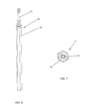
Figure 6 - it is a perspective view of the injection lance of the present invention; and -
Figure 7 - it is a section view of the injection lance of the present invention. - As already mentioned, the present invention discloses as an improvement, in relation to the prior art, a polygonal cross-section in the outer layer of refractory concrete for injection lances, aiming thereby reducing the difference of physical properties, as porosity and density, in such zones of the refractory material, due to the greater homogeneity obtained by the reduction of time and vibration intensity in the production process. Said shorter time of filling and vibration reduces the segregation tendency of smaller and lighter particles for the upper part of the piece, that is to say, the feeding point. Such gains are due to the fact that the polygonal shape offers greater thickness of the filling zone of the mold if compared to the cylindrical shape of the prior art. Besides the gains in the productive process, the greater homogeneity of the refractory matrix reduces the probability of accelerated wear of the closing zone of the mold, contributing thus for the increasing of the useful life of the injection lance.
- As can be seen from
figure 1 , which presents a sectional view of the feeding section of a mold of aninjection lance 1 of the prior art, in order to have afeeding opening 2 of themold 4 is necessary the loss of a circular arc section of refractory material, which entails a decrease in thickness ofrefractory material 5 in this point. For therefractory material loss 5 and the correspondent loss of coating thickness until theinner pipe 3 to be as smaller as possible, thefeeding opening 2 should be as narrowest as possible. With a narrow feeding opening 2 the filling time is necessarily long, which results in segregation of the material and fibers which composes the refractory concrete. As a result, the apparent porosity of the refractory in the base and in the middle of the molded piece is smaller than in the top. Such heterogeneous distribution of porosity is harmful for the useful life of theinjection lance 1. - In
Figure 2 it is shown a top view of the feeding opening 2 of amold 4 of aninjection lance 1 of the prior art. Through the feeding opening it can be seen in theinner pipe 3, which will be coated with refractory concrete. As can be seen, due to the necessity to limit the loss of thickness in theopening feeding zone 2, its width is considerably narrow. In an example of embodiment of the invention for a lance of 250 mm outer diameter, the width of the opening of the mold is only 50 mm. On the other hand, infigure 3 , which shows a top view of the feeding opening 12 ofmold 14 for aninjection lance 11 of the present invention, it is evident that the polygonal outer shape ofmold 14 allows that thefeeding opening 12 is placed fully occupying one side of the polygon. In an example of embodiment of the invention, where theinjection lance 11 have an outer diameter of 250 mm thefeeding opening 12 of the mold has a width of 150 mm, that is to say, three times the width of a lance opening equivalent to the prior art, according tofigure 2 . By theopening 12 of themold 14, it can be easily visualized theinner pipe 13 with thedocking elements 15 for fixing the mass of refractory concrete ininner pipe 13. - In
figure 4 , which is a top view of the section of the feed opening 12 of amold 14 for aninjection lance 11 of the present invention, can be easily verified that the texture of the mass ofrefractory concrete 16, in the moment of the feeding is such that necessarily requires a stage of vibration for its accommodation within theform 14. The total length of themold 14 corresponds to total length coated withrefractory concrete 16 of theinjection lance 11. - The
polygonal mold 14 and itsrespective injection lance 11 produced shows preferably an even number of sides to facilitate the support ofmold 14 in a vibratory foundation. - The steps for the method of preparation of the
injection lance 11 according to the present invention are: - 1 - Preparation of the
mold 14 and the correspondent assembly of theinner pipe 13 therein, - 2 - Filling with
refractory concrete 16 and applying vibration, - 3 - Cure of the
refractory concrete 16 withinmold 14, - 4 - Removal of
mold 14 releasing the injection lance 11 already in its final shape, and - 5 - Burning of injection lance 11 in appropriate oven.
- In comparison with the necessary steps for the production of an injection lance of the prior art, in the present invention the filling of the mass of the
refractory concrete 16 is carried out in a significantly shorter time, whereas the vibration ofmold 14 is necessary only in the final phase of the filling due to the ease of access. Infigure 5 is illustrated a view in top perspective of a feed section ofmold 14 for aninjection lance 11 of the present invention fully filled withrefractory concrete 16 having, thus, followed thesteps - It can be perceived that the external face of the refractory concrete used 16 completely fills the opening of filling 12 of
mold 14. - In an example of embodiment of the invention of a lance with outer diameter of 250 mm and a length of the
injection lance 11 of 2400 mm, according to the present invention, the weight of filler material is 300 Kg, the time of filling of 3 minutes and the vibration time of 2 minutes. - In
Figure 6 , which shows a perspective view of theinjection lance 11 of the present invention, the outer faces of the polygon, which composes the surface of therefractory concrete mass 16 that can be observed. The extremity ofinner pipe 13 can be also seen. - Other advantage of the
injection lance 11 of the present invention is that the vertices of the polygon act as sacrifice material, since they tend to concentrate the tension and chip or break during use, reducing, then, the mechanical and thermomechanical stress in the cylindrical region within the radial polygonal profile. - At last,
figure 7 shows cutaway section of aninjection lance 11 of the present invention, where it can be seen theinner pipe 13 and therefractory concrete 16 with an external polygonal profile. - In the embodiment example of the present invention one hexagonal external profile for the
refractory concrete 16 is submitted. It is evident for a person skilled in the art that the polygonal profile can have square shape, pentagonal, octogonal, decagonal, etc., besides the hexagonal shown, always according to the diameter of the injection lance and the best relation of face width to theopening feed 12. - Furthermore, the use of such outer profile of the
refractory concrete 16 can occur in a determined zone of the injection lance 21 or throughout the whole length of the refractoryconcrete coating 16, as showed in the example of embodiment of the invention above. It is also clear that the outer polygonal profile of the refractoryconcrete coating 16 can be used in any type of lance for the use in metallurgical vessels. - Since it was described an example of preferred embodiment, it should be understood that the scope of the present invention encompasses other possible variations, being limited solely by the wording of the appended claims, including therein the possible equivalents.
Claims (7)
- Lance for top injection in metallurgical vessels, which is used essentially for the refining process of pig iron and steel production, wherein the lance (11) has at least one inner tube (13) and a cover of refractory concrete (16), charactererized in that the external profile of the cover of refractory concrete (16) is polygonal.
- Lance for top injection in metallurgical vessels according to claim 1, characterized in that the outer profile of the refractory concrete coating (16) is a polygon with an even number of sides.
- Lance for Top injection in metallurgical vessels according to claim 2, characterized in that the outer profile of the refractory concrete coating (16) is a hexagon.
- Lance for top injection in metallurgical vessels according to claim 1, characterized in that it is produced in a mold (14) of a polygonal shape.
- Lance for top injection in metallurgical vessels according to claim 4, characterized in that the mold (14) presents a feed opening (12) placed on one side of the polygon.
- Lance for top injection in metallurgical vessels according to claim 5, characterized by the feed opening (12) to fill completely the width of the outer face of the polygonal mold (14).
- Method of production of an injection lance (11), as defined in any of claims 1 to 6, including the steps of:- 1 - preparation of the mold (14) and the correspondent assem-bly of inner pipe 13 therein,- 2 - filling with refractory concrete (16) and applying vibration,- 3 - cure of the refractory concrete (16) within the mold (14),- 4 - removal of the mold (14) releasing the injection lance (11) already in its final shape, and- 5 - burning of the injection lance (11) in an oven, characterized by the vibration of the mold (14) to occur only in the end of the filling step.
Applications Claiming Priority (2)
| Application Number | Priority Date | Filing Date | Title |
|---|---|---|---|
| BRPI1102228-0A2A BRPI1102228A2 (en) | 2011-05-17 | 2011-05-17 | top injection lance in metallurgical vessels and method of manufacture of this lance |
| PCT/BR2012/000131 WO2012155225A1 (en) | 2011-05-17 | 2012-05-10 | Lance for top injection in metallurgical vessels and method for the production of said lance |
Publications (2)
| Publication Number | Publication Date |
|---|---|
| EP2712938A1 true EP2712938A1 (en) | 2014-04-02 |
| EP2712938A4 EP2712938A4 (en) | 2014-11-05 |
Family
ID=47176065
Family Applications (1)
| Application Number | Title | Priority Date | Filing Date |
|---|---|---|---|
| EP12786183.9A Withdrawn EP2712938A4 (en) | 2011-05-17 | 2012-05-10 | Lance for top injection in metallurgical vessels and method for the production of said lance |
Country Status (7)
| Country | Link |
|---|---|
| US (1) | US20150315664A1 (en) |
| EP (1) | EP2712938A4 (en) |
| KR (1) | KR20140053018A (en) |
| AR (1) | AR086404A1 (en) |
| BR (1) | BRPI1102228A2 (en) |
| CA (1) | CA2839175A1 (en) |
| WO (1) | WO2012155225A1 (en) |
Cited By (3)
| Publication number | Priority date | Publication date | Assignee | Title |
|---|---|---|---|---|
| WO2016166189A1 (en) | 2015-04-16 | 2016-10-20 | Vesuvius Crucible Company | Lance for top injection in metallurgical vessels and process for manufacturing same |
| EP3922736A1 (en) * | 2020-06-08 | 2021-12-15 | ImerTech SAS | Blast lance for gas blowing, its use and method of production |
| CN118417827A (en) * | 2024-05-17 | 2024-08-02 | 鞍山市和丰耐火材料有限公司 | A method for manufacturing an assembled molten iron pretreatment desulfurization spray gun body and a spray gun |
Families Citing this family (1)
| Publication number | Priority date | Publication date | Assignee | Title |
|---|---|---|---|---|
| WO2021110259A1 (en) | 2019-12-04 | 2021-06-10 | Refractory Intellectual Property Gmbh & Co. Kg | Refractory casting nozzle for a changing device arranged at the outlet of a metallurgical vessel |
Family Cites Families (6)
| Publication number | Priority date | Publication date | Assignee | Title |
|---|---|---|---|---|
| US4433832A (en) * | 1982-12-27 | 1984-02-28 | Inland Enterprises, Inc. | Metallurgical lance |
| US4854553A (en) * | 1988-06-03 | 1989-08-08 | Labate M D | Self shielding lance |
| GB2230848B (en) * | 1989-04-26 | 1993-01-13 | Insul Co Inc | Lance for use in treating a bath of molten metal |
| JPH08157928A (en) | 1994-10-06 | 1996-06-18 | Nippon Steel Corp | Top blowing lance for converter with low dust generation |
| DE4442362C1 (en) * | 1994-11-18 | 1996-04-18 | Mannesmann Ag | Method and appts. for performing a variety of processes on a melt using standard equipment |
| KR100227066B1 (en) * | 1995-01-06 | 1999-10-15 | 아사무라 타카싯 | Converter top blow refining method having excellent decarburization characteristics and top blow lance for converter |
-
2011
- 2011-05-17 BR BRPI1102228-0A2A patent/BRPI1102228A2/en not_active Application Discontinuation
-
2012
- 2012-05-10 EP EP12786183.9A patent/EP2712938A4/en not_active Withdrawn
- 2012-05-10 KR KR1020137033010A patent/KR20140053018A/en not_active Withdrawn
- 2012-05-10 US US13/816,802 patent/US20150315664A1/en not_active Abandoned
- 2012-05-10 WO PCT/BR2012/000131 patent/WO2012155225A1/en not_active Ceased
- 2012-05-10 CA CA2839175A patent/CA2839175A1/en not_active Abandoned
- 2012-05-15 AR ARP120101713A patent/AR086404A1/en unknown
Cited By (6)
| Publication number | Priority date | Publication date | Assignee | Title |
|---|---|---|---|---|
| WO2016166189A1 (en) | 2015-04-16 | 2016-10-20 | Vesuvius Crucible Company | Lance for top injection in metallurgical vessels and process for manufacturing same |
| EP3922736A1 (en) * | 2020-06-08 | 2021-12-15 | ImerTech SAS | Blast lance for gas blowing, its use and method of production |
| WO2021250032A1 (en) * | 2020-06-08 | 2021-12-16 | Imertech Sas | Blast lance for gas blowing, its use and method of production |
| CN115698341A (en) * | 2020-06-08 | 2023-02-03 | 伊梅斯切公司 | Blast lance for gas injection, its use and production method |
| US12529521B2 (en) | 2020-06-08 | 2026-01-20 | Imertech Sas | Blast lance for gas blowing, its use and method of production |
| CN118417827A (en) * | 2024-05-17 | 2024-08-02 | 鞍山市和丰耐火材料有限公司 | A method for manufacturing an assembled molten iron pretreatment desulfurization spray gun body and a spray gun |
Also Published As
| Publication number | Publication date |
|---|---|
| AR086404A1 (en) | 2013-12-11 |
| EP2712938A4 (en) | 2014-11-05 |
| WO2012155225A1 (en) | 2012-11-22 |
| KR20140053018A (en) | 2014-05-07 |
| BRPI1102228A2 (en) | 2013-06-25 |
| US20150315664A1 (en) | 2015-11-05 |
| CA2839175A1 (en) | 2012-11-22 |
Similar Documents
| Publication | Publication Date | Title |
|---|---|---|
| US20150315664A1 (en) | Lance for top injection in metallurgical vessels and method for the production of said lance | |
| KR102453986B1 (en) | Tundish exit changer | |
| JP2016190234A (en) | Alternative cone crusher wear liner | |
| EP3093124B1 (en) | Improvements in additive layer manufacturing methods | |
| JP2010058155A (en) | Ceramic composite member | |
| JP2019524449A (en) | Collision pad | |
| AU2013255616B2 (en) | Neck-down feeder | |
| US8499818B2 (en) | Encapsulated solid ceramic element | |
| US20140175715A1 (en) | Method And Arrangement For Vortex Reduction In A Metal Making Process | |
| KR20190051021A (en) | Material hopper, material hopper for furnace | |
| WO2013152946A1 (en) | A method for producing shot from melt, a device for carrying out same, a device for cooling melt fragments, and a die for producing shot from melt | |
| EP4279201A1 (en) | Method for casting a component for application in a high wear industrial environment and such a casted component | |
| JP7196753B2 (en) | Liner and manufacturing method thereof | |
| EP3405730B1 (en) | Refractory anchor for a furnace refractory tile | |
| JP2011074439A (en) | Immersion tube for refining apparatuses | |
| EP2390026A2 (en) | Forming a cast component with agitation | |
| CA3008702C (en) | Refractory anchor for a furnace refractory tile | |
| RU2576386C1 (en) | Method for surface alloying of steel castings | |
| JP6715783B2 (en) | Unfired end brick for molten metal outlet | |
| KR20200011469A (en) | Manufacturing method of sintered ore | |
| JP6886358B2 (en) | Lining method at the bottom of the electric furnace | |
| Asensio Lozano et al. | Microstructural optimization of unalloyed ductile cast irons with a ferritic matrix used in the manufacture of wind turbine rotors | |
| US20050067129A1 (en) | Method for the production of hollow ingots of a metallic material or of a plurality of metallic materials | |
| WO2007053127A2 (en) | Method for manufacture of composite deoxiden | |
| WO2006077786A1 (en) | Reverse slant lining structure of furnace with reduced part structure |
Legal Events
| Date | Code | Title | Description |
|---|---|---|---|
| PUAI | Public reference made under article 153(3) epc to a published international application that has entered the european phase |
Free format text: ORIGINAL CODE: 0009012 |
|
| 17P | Request for examination filed |
Effective date: 20131216 |
|
| AK | Designated contracting states |
Kind code of ref document: A1 Designated state(s): AL AT BE BG CH CY CZ DE DK EE ES FI FR GB GR HR HU IE IS IT LI LT LU LV MC MK MT NL NO PL PT RO RS SE SI SK SM TR |
|
| DAX | Request for extension of the european patent (deleted) | ||
| A4 | Supplementary search report drawn up and despatched |
Effective date: 20141002 |
|
| RIC1 | Information provided on ipc code assigned before grant |
Ipc: C21C 7/072 20060101ALI20140926BHEP Ipc: C21C 5/46 20060101ALI20140926BHEP Ipc: C21C 1/00 20060101ALI20140926BHEP Ipc: C21C 5/52 20060101ALN20140926BHEP Ipc: F27D 3/16 20060101ALN20140926BHEP Ipc: C21C 5/32 20060101AFI20140926BHEP |
|
| STAA | Information on the status of an ep patent application or granted ep patent |
Free format text: STATUS: THE APPLICATION IS DEEMED TO BE WITHDRAWN |
|
| 18D | Application deemed to be withdrawn |
Effective date: 20150501 |