EP3283441B1 - Method and system for anaerobic treatment of organically loaded wastewater - Google Patents
Method and system for anaerobic treatment of organically loaded wastewater Download PDFInfo
- Publication number
- EP3283441B1 EP3283441B1 EP16735725.0A EP16735725A EP3283441B1 EP 3283441 B1 EP3283441 B1 EP 3283441B1 EP 16735725 A EP16735725 A EP 16735725A EP 3283441 B1 EP3283441 B1 EP 3283441B1
- Authority
- EP
- European Patent Office
- Prior art keywords
- unit
- fraction
- outlet
- reactor
- separating
- Prior art date
- Legal status (The legal status is an assumption and is not a legal conclusion. Google has not performed a legal analysis and makes no representation as to the accuracy of the status listed.)
- Active
Links
- 238000000034 method Methods 0.000 title claims description 32
- 239000002351 wastewater Substances 0.000 title claims description 30
- 239000007787 solid Substances 0.000 claims description 32
- 238000009299 dissolved gas flotation Methods 0.000 claims description 27
- 239000010802 sludge Substances 0.000 claims description 23
- 239000010815 organic waste Substances 0.000 claims description 18
- 239000000701 coagulant Substances 0.000 claims description 13
- 239000007788 liquid Substances 0.000 claims description 13
- 238000005188 flotation Methods 0.000 claims description 10
- 239000000203 mixture Substances 0.000 claims description 9
- 238000005498 polishing Methods 0.000 claims description 5
- 239000008394 flocculating agent Substances 0.000 claims description 3
- 238000011144 upstream manufacturing Methods 0.000 claims description 3
- 238000002347 injection Methods 0.000 claims 2
- 239000007924 injection Substances 0.000 claims 2
- 150000004696 coordination complex Chemical class 0.000 claims 1
- 238000002203 pretreatment Methods 0.000 description 12
- 230000014759 maintenance of location Effects 0.000 description 9
- 239000000126 substance Substances 0.000 description 8
- QVGXLLKOCUKJST-UHFFFAOYSA-N atomic oxygen Chemical compound [O] QVGXLLKOCUKJST-UHFFFAOYSA-N 0.000 description 5
- 235000013305 food Nutrition 0.000 description 5
- 239000001301 oxygen Substances 0.000 description 5
- 229910052760 oxygen Inorganic materials 0.000 description 5
- 235000019219 chocolate Nutrition 0.000 description 4
- 230000029087 digestion Effects 0.000 description 4
- 238000009300 dissolved air flotation Methods 0.000 description 4
- 235000013361 beverage Nutrition 0.000 description 3
- 235000013365 dairy product Nutrition 0.000 description 3
- 239000004744 fabric Substances 0.000 description 3
- 239000003925 fat Substances 0.000 description 3
- 238000010438 heat treatment Methods 0.000 description 3
- 239000003921 oil Substances 0.000 description 3
- 235000019198 oils Nutrition 0.000 description 3
- 229920000642 polymer Polymers 0.000 description 3
- 238000000926 separation method Methods 0.000 description 3
- 239000002699 waste material Substances 0.000 description 3
- 238000004065 wastewater treatment Methods 0.000 description 3
- 239000002028 Biomass Substances 0.000 description 2
- 230000033228 biological regulation Effects 0.000 description 2
- 235000013351 cheese Nutrition 0.000 description 2
- 238000006243 chemical reaction Methods 0.000 description 2
- 238000005520 cutting process Methods 0.000 description 2
- 239000007789 gas Substances 0.000 description 2
- 230000007062 hydrolysis Effects 0.000 description 2
- 238000006460 hydrolysis reaction Methods 0.000 description 2
- 230000002401 inhibitory effect Effects 0.000 description 2
- 239000012528 membrane Substances 0.000 description 2
- 239000002184 metal Substances 0.000 description 2
- 229910052751 metal Inorganic materials 0.000 description 2
- 238000012856 packing Methods 0.000 description 2
- 238000009928 pasteurization Methods 0.000 description 2
- 238000004659 sterilization and disinfection Methods 0.000 description 2
- 241000894006 Bacteria Species 0.000 description 1
- 241001149900 Fusconaia subrotunda Species 0.000 description 1
- 241000287828 Gallus gallus Species 0.000 description 1
- 241001465754 Metazoa Species 0.000 description 1
- 235000019482 Palm oil Nutrition 0.000 description 1
- 229910000831 Steel Inorganic materials 0.000 description 1
- 241000282887 Suidae Species 0.000 description 1
- 230000002411 adverse Effects 0.000 description 1
- 238000005273 aeration Methods 0.000 description 1
- 230000009286 beneficial effect Effects 0.000 description 1
- 235000013330 chicken meat Nutrition 0.000 description 1
- 238000004140 cleaning Methods 0.000 description 1
- 239000002131 composite material Substances 0.000 description 1
- 150000001875 compounds Chemical class 0.000 description 1
- 239000012141 concentrate Substances 0.000 description 1
- 235000009508 confectionery Nutrition 0.000 description 1
- 238000013461 design Methods 0.000 description 1
- 239000005446 dissolved organic matter Substances 0.000 description 1
- 239000012530 fluid Substances 0.000 description 1
- 238000005187 foaming Methods 0.000 description 1
- 239000010794 food waste Substances 0.000 description 1
- 238000005469 granulation Methods 0.000 description 1
- 230000003179 granulation Effects 0.000 description 1
- 239000004519 grease Substances 0.000 description 1
- 235000015243 ice cream Nutrition 0.000 description 1
- 239000010842 industrial wastewater Substances 0.000 description 1
- 238000004519 manufacturing process Methods 0.000 description 1
- 235000013372 meat Nutrition 0.000 description 1
- -1 metal complexes Chemical class 0.000 description 1
- 244000005700 microbiome Species 0.000 description 1
- 230000003647 oxidation Effects 0.000 description 1
- 238000007254 oxidation reaction Methods 0.000 description 1
- 239000002540 palm oil Substances 0.000 description 1
- 239000000123 paper Substances 0.000 description 1
- 238000011084 recovery Methods 0.000 description 1
- 238000004064 recycling Methods 0.000 description 1
- 239000002002 slurry Substances 0.000 description 1
- 239000010959 steel Substances 0.000 description 1
- 238000003860 storage Methods 0.000 description 1
- 238000013517 stratification Methods 0.000 description 1
- 239000000758 substrate Substances 0.000 description 1
- 238000012360 testing method Methods 0.000 description 1
- 239000002562 thickening agent Substances 0.000 description 1
- 241001148471 unidentified anaerobic bacterium Species 0.000 description 1
- 235000013311 vegetables Nutrition 0.000 description 1
- 239000002023 wood Substances 0.000 description 1
Images
Classifications
-
- C—CHEMISTRY; METALLURGY
- C02—TREATMENT OF WATER, WASTE WATER, SEWAGE, OR SLUDGE
- C02F—TREATMENT OF WATER, WASTE WATER, SEWAGE, OR SLUDGE
- C02F3/00—Biological treatment of water, waste water, or sewage
- C02F3/28—Anaerobic digestion processes
- C02F3/2813—Anaerobic digestion processes using anaerobic contact processes
-
- C—CHEMISTRY; METALLURGY
- C02—TREATMENT OF WATER, WASTE WATER, SEWAGE, OR SLUDGE
- C02F—TREATMENT OF WATER, WASTE WATER, SEWAGE, OR SLUDGE
- C02F1/00—Treatment of water, waste water, or sewage
- C02F1/24—Treatment of water, waste water, or sewage by flotation
-
- C—CHEMISTRY; METALLURGY
- C02—TREATMENT OF WATER, WASTE WATER, SEWAGE, OR SLUDGE
- C02F—TREATMENT OF WATER, WASTE WATER, SEWAGE, OR SLUDGE
- C02F3/00—Biological treatment of water, waste water, or sewage
- C02F3/02—Aerobic processes
- C02F3/12—Activated sludge processes
- C02F3/1205—Particular type of activated sludge processes
- C02F3/1215—Combinations of activated sludge treatment with precipitation, flocculation, coagulation and separation of phosphates
-
- C—CHEMISTRY; METALLURGY
- C02—TREATMENT OF WATER, WASTE WATER, SEWAGE, OR SLUDGE
- C02F—TREATMENT OF WATER, WASTE WATER, SEWAGE, OR SLUDGE
- C02F3/00—Biological treatment of water, waste water, or sewage
- C02F3/28—Anaerobic digestion processes
- C02F3/286—Anaerobic digestion processes including two or more steps
-
- C—CHEMISTRY; METALLURGY
- C02—TREATMENT OF WATER, WASTE WATER, SEWAGE, OR SLUDGE
- C02F—TREATMENT OF WATER, WASTE WATER, SEWAGE, OR SLUDGE
- C02F3/00—Biological treatment of water, waste water, or sewage
- C02F3/28—Anaerobic digestion processes
- C02F3/2866—Particular arrangements for anaerobic reactors
-
- C—CHEMISTRY; METALLURGY
- C02—TREATMENT OF WATER, WASTE WATER, SEWAGE, OR SLUDGE
- C02F—TREATMENT OF WATER, WASTE WATER, SEWAGE, OR SLUDGE
- C02F2103/00—Nature of the water, waste water, sewage or sludge to be treated
- C02F2103/32—Nature of the water, waste water, sewage or sludge to be treated from the food or foodstuff industry, e.g. brewery waste waters
- C02F2103/322—Nature of the water, waste water, sewage or sludge to be treated from the food or foodstuff industry, e.g. brewery waste waters from vegetable oil production, e.g. olive oil production
-
- C—CHEMISTRY; METALLURGY
- C02—TREATMENT OF WATER, WASTE WATER, SEWAGE, OR SLUDGE
- C02F—TREATMENT OF WATER, WASTE WATER, SEWAGE, OR SLUDGE
- C02F2103/00—Nature of the water, waste water, sewage or sludge to be treated
- C02F2103/32—Nature of the water, waste water, sewage or sludge to be treated from the food or foodstuff industry, e.g. brewery waste waters
- C02F2103/327—Nature of the water, waste water, sewage or sludge to be treated from the food or foodstuff industry, e.g. brewery waste waters from processes relating to the production of dairy products
-
- C—CHEMISTRY; METALLURGY
- C02—TREATMENT OF WATER, WASTE WATER, SEWAGE, OR SLUDGE
- C02F—TREATMENT OF WATER, WASTE WATER, SEWAGE, OR SLUDGE
- C02F2203/00—Apparatus and plants for the biological treatment of water, waste water or sewage
- C02F2203/002—Apparatus and plants for the biological treatment of water, waste water or sewage comprising an initial buffer container
-
- Y—GENERAL TAGGING OF NEW TECHNOLOGICAL DEVELOPMENTS; GENERAL TAGGING OF CROSS-SECTIONAL TECHNOLOGIES SPANNING OVER SEVERAL SECTIONS OF THE IPC; TECHNICAL SUBJECTS COVERED BY FORMER USPC CROSS-REFERENCE ART COLLECTIONS [XRACs] AND DIGESTS
- Y02—TECHNOLOGIES OR APPLICATIONS FOR MITIGATION OR ADAPTATION AGAINST CLIMATE CHANGE
- Y02E—REDUCTION OF GREENHOUSE GAS [GHG] EMISSIONS, RELATED TO ENERGY GENERATION, TRANSMISSION OR DISTRIBUTION
- Y02E50/00—Technologies for the production of fuel of non-fossil origin
- Y02E50/30—Fuel from waste, e.g. synthetic alcohol or diesel
-
- Y—GENERAL TAGGING OF NEW TECHNOLOGICAL DEVELOPMENTS; GENERAL TAGGING OF CROSS-SECTIONAL TECHNOLOGIES SPANNING OVER SEVERAL SECTIONS OF THE IPC; TECHNICAL SUBJECTS COVERED BY FORMER USPC CROSS-REFERENCE ART COLLECTIONS [XRACs] AND DIGESTS
- Y02—TECHNOLOGIES OR APPLICATIONS FOR MITIGATION OR ADAPTATION AGAINST CLIMATE CHANGE
- Y02W—CLIMATE CHANGE MITIGATION TECHNOLOGIES RELATED TO WASTEWATER TREATMENT OR WASTE MANAGEMENT
- Y02W10/00—Technologies for wastewater treatment
- Y02W10/10—Biological treatment of water, waste water, or sewage
Definitions
- the present invention relates to a method for anaerobic treatment of an organic wastewater and organic waste streams.
- the invention relates to a system for anaerobic treatment of such an organic wastewater and organic waste streams.
- TSS total suspended solids
- FOG fats, oils and greases
- Wastewater with high levels of COD (Chemical Oxygen Demand), TSS and FOG can be found in many parts of the food and beverage industry, such as ice cream, chocolate, candy, vegetable, dairy and cheese factories. Also Palm Oil Mill Effluent (POME) falls into this category.
- COD Chemical Oxygen Demand
- TSS and FOG can be found in many parts of the food and beverage industry, such as ice cream, chocolate, candy, vegetable, dairy and cheese factories.
- Palm Oil Mill Effluent (POME) falls into this category.
- the treatment process for such factories consists of a pre-treatment step, typically a physical-chemical treatment, to remove the free fats and solids, sometimes followed by high-rate anaerobic treatment, then generally followed by an aerobic biological treatment plant to achieve the discharge requirements.
- the pre-treatment step is essential for producing a wastewater which is suitable for the aerobic micro-organisms.
- Known issues with not properly pre-treated wastewaters are: foaming, sludge bulking, grease layers on aeration tanks, and poor settling characteristics.
- the result of a process with chemical pre-treatment is a good quality wastewater, but it also produces a chemically treated sludge from the pre-treatment and excess aerobic biological sludge.
- an anaerobic digester for treatment of industrial wastewater in which the influent stream may be a single stream or a composite stream of two or more waste streams.
- a solid-liquid separation device which may be a sludge screw thickener, treats a stream from the digester in a recirculation loop. The solids portion is returned to the digester to increase the solids retention time and the TSS in the digester. This allows the SRT to be controlled separately from the hydraulic retention time HRT. A liquid portion with less than 5% solids in the stream is removed and treated further in a polishing unit.
- Another object is to provide a relatively low cost separator downstream from the anaerobic reactor.
- a further object is to provide downstream from the anaerobic reactor a separator that can be operated with a gas that is derived from the ambient.
- a method of anaerobic treatment of an organic waste stream is provided in accordance with claim 1.
- the output stream of the anaerobic reactor can be concentrated and the solids can for the largest part be fed back into the reactor.
- the liquid fraction from the first separating unit contains reduced amounts of TSS and can be effectively treated in a dissolved gas flotation (DGF) unit of relatively small size (decrease in size between 50-80%).
- DGF dissolved gas flotation
- the method according to the invention provides a very good solution to treat both an organic waste wastewater and organic waste solids in a single process, with a high efficiency and allowing for a rather compact system design.
- the Solids Retention Time SRT
- HRT Hydraulic Retention Time
- the solids-liquid separation is a Dissolved Biogas Flotation (DBF) system.
- DBF Dissolved Biogas Flotation
- the pre-separator upstream of the DBF/DGF is a vacuum filter press or a cloth filter,a dynamic filter based on centrifugal forces, like a cyclone or a centrifuge or a DGF without or relative little the addition of flocculants and/or coagulants.
- the method according to the invention is beneficial for those fluids for which the SRT needs to be substantially higher than the HRT to obtain a stable and good process.
- one or more waste streams can be dealt with in one system and a high level of conversion to biogas can be achieved.
- a post-aerobic biological treatment may be required.
- the excess sludge from this aerobic system can be returned to the anaerobic reactor, which is another advantage over high rate (UASB-type) reactors.
- the method according to the invention provides approximately 20% lower operational costs compared to a method wherein a chemical treatment step is followed by a step involving a UASB-type reactor.
- a flocculant and/or coagulant is added to the second fraction in a dosage of between 1-12 g flocculant/kg dry solids , preferably between 3-9 g flocculant/kg dry solids, more preferably between 3-6 kg flocculant/g dry solids.
- the relatively low amounts of flocculant polymer allow effective operation of the Dissolved Gas Flotation unit.
- the flocculant and/or coagulant may comprise relatively cheap compounds such as metal complexes, for instance Al or Fe in a dosage of between 50-1000 ppm, preferably between 100-400, so that it is more cost-effective.
- the DGF unit may be operated using biogas from the anaerobic reactor to minimise the oxygen level is in the feedback stream to the anaerobic reactor. Instead of biogas air can be used after removing the majority of the oxygen.
- DAF Dissolved Air Flotation
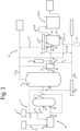
- FIG. 1 shows a system 22 for anaerobic treatment of an organic wastewater and organic waste streams 1.
- the system 22 comprises an equalization buffer 3, for instance in the form of a pump sump or a mixing tank, provided with a primary inlet 23 arranged to receive a primary stream 2 of organic wastewater.
- the organic wastewater 1 may for instance comprise wastewater from a dairy, chocolate or cheese factory, comprising slurries, liquids (such as in the case of chocolate factories).
- An anaerobic reactor 5 is connected to an outlet 24 of the equalization buffer 3.
- An outlet 40 of the reactor 5 is connected to a pre-separating unit 33.
- a first outlet 35 of the pre-separating unit 33 is connected to a feedback inlet 41 of the reactor 5 for feeding back a stream 7" containing between 50 % and 80 % of the solids by weight into the reactor 5.
- a second outlet 36 of the pre-separating unit 33 is connected to an input 42 of a separator 16 for supplying a low solids stream 7 into the separator 16.
- the separator 16 which may be DGF unitor a DAF unit as described in EP 1 735 070 in the name of the applicant, the reactor mixture 7 is separated into a liquid fraction 8 and a sludge fraction 9. The sludge fraction 9 is fed back to the feedback inlet 41 of the reactor 5.
- the anaerobic reactor 5 may be cylindrical with a double membrane roof. If desired, multiple subsequent anaerobic reactors 5 may be used, wherein the first reactor is a relatively large reactor and the second reactor is fitted with a membrane roof for gas storage (not shown). Preferably, mixing devices (not shown) are installed in the reactor 5 to enhance mixing and avoid stratification.
- the temperature in the reactor 5 may be controlled by steel tubing in the wall of the reactor 5, which act as a heat exchanger.
- the hydraulic retention time may vary between 1-14 days.
- the organic loading will typically depend on substrates and solids and will typically be between 2-20, preferably 3-7 kg COD/m 3 /day. Recycling of solids is required to achieve the desired organic loading and to attain a sufficiently long solids retention time (SRT).
- the equalization buffer 3 can be left out, such that the primary 2 and secondary 11 streams flow directly to the reactor 5 (as indicated by the dashed lines).
- a flocculant and/or coagulant feeder 6 is provided and is connected to the inlet 42 of the separator 16, wherein the feeder is arranged for dosing the flocculant and/or coagulant at 1-12, preferably 3-9, more preferably 3-6, g flocculant/kg dry solids.
- the separator 16 of figure 1 can be a dissolved biogas flotation (DBF) separator 16, comprising a liquid fraction outlet 25, a sludge fraction outlet 26 connected to the feedback inlet 41 of the anaerobic reactor 5, and a secondary inlet 27 that is arranged to receive biogas from the anaerobic reactor 5.
- DPF dissolved biogas flotation
- treated air containing less oxygen or untreated air may be introduced into secondary inlet 43, so that the reactor is a Dissolved Air Flotation unit.
- the air may be supplied by a compressor 37 that draws in air from the ambient.
- the air supply has been indicated in a dashed line and may be used in combination with or instead of supplying biogas via the inlet 27.
- a further separator unit 44 is comprised upstream of the inlet 41 of the anaerobic reactor to further remove liquid from the stream returned to the anaerobic reactor to 4-30% TSS
- the equalization buffer 3 further comprises a secondary inlet 28 arranged to receive a secondary stream 11 comprising organic waste solids.
- the separator 16 may be gastight to prevent biogas from escaping and/or exposing the anaerobic bacteria to outside air, which, depending on the type of bacteria, could kill them. It was found however, that the use of the pre-separating unit 33 allows supply of air into the separator 16 without adversely affecting the anaerobic reactions in the reactor 5.
- the system 22 may further comprise a pre-treatment unit 12 comprising a main inlet 29 and an outlet 30 connected to the secondary inlet 28 of the equalization buffer 3.
- the pre-treatment unit 12 can be a de-packing unit, cutting unit, shredding unit, pasteurisation unit, sterilisation unit, oxidation unit, solubilisation unit, hydrolysis unit or any combination thereof.
- the type of pre-treatment depends on the type of product, country (regulations) and process requirements.
- a screen may be used to remove larger debris, like cloth, wood or paper.
- a pre-separator (indicated by the frustoconical shape, with reference numeral 33) may be installed before the DGF 16, to be able to dose a flocculant to reduce tank volume even further.
- Such a pre-separator 33 is a vacuum filter press or a cloth filter, a dynamic filter based on centrifugal forces, like a cyclone or a centrifuge or a DGF, without or with little addition
- the system 22 is used with two anaerobic reactors 5, with a volume of 600-900, such as 750 m3, each.
- a pipe reactor with flocculant dosing is used. This system can for instance be used with a chocolate factory.
- a typical wastewater volume then is 100 m 3 /d with a COD concentration varying between 10-60 g/l at an average of 37 g/l.
- the separator/flotation device 16 is operated at 5 m 3 /h. Applicant has been able to achieve consistently stable results with the above parameters and flocculant dose used. TSS and COD removal percentages of more than 95% were achieved for the wastewater from the DBF 16.
- the method of anaerobic treatment of an organic wastewater and organic waste streams comprises the steps of
- the method is carried out in mesophilic conditions (25-42° C), although thermophilic conditions (43-60° C) can also be used.
- the method step of (a) feeding the primary stream 2 of organic wastewater and organic waste streams 1 further may comprise the step of feeding the secondary stream 11 of the organic waste solids to the equalization buffer 3.
- Feeding the secondary stream 11 of organic waste solids may comprise proportionally feeding the second stream 11 to the equalization buffer 3 to obtain a more consistent mixture.
- feeding the secondary stream of organic waste solids may comprise a pre-treatment 12 thereof comprising de-packing, cutting, shredding, pasteurisation, sterilisation, solubilisation or hydrolysis, or any combination thereof.
- the method step of (a) feeding the primary stream 2 of organic wastewater further may comprise separating the primary stream 2 of organic wastewater into a first fraction 13 and a second fraction 14, and feeding the first fraction 13 to the equalization buffer 3 and the second fraction 14 to the pre-treatment 12.
- the method step of feeding the buffer mixture 4 further comprises preheating the buffer mixture 4 from the equalization buffer 3 by a heating unit (not shown).
- the heating unit can also be used to heat raw waste water entering the equalization buffer 3.
- a heat recovery system is used, wherein heat from wastewater is used to heat further wastewater, for instance via a heat exchanger.
- the method step of separating the reactor mixture 7 may comprise feeding biogas 15 from the anaerobic reactor to a dissolved biogas flotation separator (DGF) 16. Therein, 5-30, preferably 5-20, more preferably around 10-15 1 biogas/kg solids, is fed to the dissolved biogas flotation separator (DBF) 16.
- the method further may comprise the step of collecting biogas 17 from the dissolved biogas flotation separator (DBF) 16 for further use, such as for heating or generation of energy.
- the method step of feeding, at least in part, the sludge fraction 9 back to the anaerobic reactor 5 further comprises collecting, at least in part, the sludge fraction 18 for further use.
- wastewater 19 from the separator 16 is subsequently subjected to a polishing step 20.
- the polishing step 20 preferably comprises aerobic treatment 21. Excess sludge originating from the polishing step 20 can be fed back to the anaerobic reactor 5.
Description
- The present invention relates to a method for anaerobic treatment of an organic wastewater and organic waste streams. In a further aspect the invention relates to a system for anaerobic treatment of such an organic wastewater and organic waste streams.
- Food and beverage production plants are major wastewater contributors and often have food waste. Particularly plants with wastewaters with a significant total suspended solids (TSS) and/or fats, oils and greases (FOG) like in the dairy, meat and chicken industry need to pre-treat their wastewater before high rate anaerobic reactors can be applied. This pre-treatment generally includes undesirable chemical treatment and generates a concentrated side stream which needs to be dealt with.
- In parts of the food and beverage industry many high-rate reactors are installed, typically on wastewaters with high dissolved organic matter and low total suspended solids (TSS) and Fats, Oils and Greases (FOG). These high rate reactors, such as UASB (Upflow Anaerobic Sludge Bed) and EGSB (Enhanced Granular Sludge Bed) reactors depend on the granulation of the consortia of biomass in the reactor. In many occasions there are problems with maintaining the granular sludge, due to the presence of solids, oils and greases or other inhibiting factors. Wastewater with high levels of COD (Chemical Oxygen Demand), TSS and FOG can be found in many parts of the food and beverage industry, such as ice cream, chocolate, candy, vegetable, dairy and cheese factories. Also Palm Oil Mill Effluent (POME) falls into this category.
- Traditionally, the treatment process for such factories consists of a pre-treatment step, typically a physical-chemical treatment, to remove the free fats and solids, sometimes followed by high-rate anaerobic treatment, then generally followed by an aerobic biological treatment plant to achieve the discharge requirements. The pre-treatment step is essential for producing a wastewater which is suitable for the aerobic micro-organisms. Known issues with not properly pre-treated wastewaters are: foaming, sludge bulking, grease layers on aeration tanks, and poor settling characteristics. The result of a process with chemical pre-treatment is a good quality wastewater, but it also produces a chemically treated sludge from the pre-treatment and excess aerobic biological sludge.
- In the past decades the sludge from pre-treatment systems has become an everincreasing problem to dispose of at ever increasing disposal costs. Decades ago these organic sludges could still be spread over land or mixed with other products to produce fodder as food for animals (pigs). More recently, in various countries, many of these sludges have to be incinerated. Lately, there is a trend to use these sludges as cosubstrate in anaerobic digestion plants, yet still at a cost to the factory producing it. Besides these sludges from the wastewater treatment processes, food factories are also producing organic wastes, which can either be rejected batches, returned products, concentrates produced during CIP cleaning, spills, et cetera.
- To deal with the sludges of pre-treatment systems (physical-chemical) anaerobic digestion systems are often installed. In these cases chemicals and equipment are needed to produce these sludges. An alternative is to mix the wastewater and organic waste together and treat it in an anaerobic digester, such as disclosed in US patent publication
US 5,015,384 . Since the wastewater is relatively diluted and the anaerobic digestion requires a solids retention time (SRT) of at least 15-20 days, such a digestion plant would require a retention time equal to the SRT. However, a reactor with a retention time of over 10 days is generally not economical. - From
WO 2013/155631 an anaerobic digester is known for treatment of industrial wastewater in which the influent stream may be a single stream or a composite stream of two or more waste streams. A solid-liquid separation device which may be a sludge screw thickener, treats a stream from the digester in a recirculation loop. The solids portion is returned to the digester to increase the solids retention time and the TSS in the digester. This allows the SRT to be controlled separately from the hydraulic retention time HRT. A liquid portion with less than 5% solids in the stream is removed and treated further in a polishing unit. - It is an object of the present invention to provide effective separation of organically loaded waste streams using an anaerobic reactor. It is another object of the invention to provide an anaerobic waste water treatment method using reduced amounts of coagulant and/or flocculant polymer. It is a further object of the invention to provide an anaerobic waste water treatment method in which the coagulant and/or flocculant polymer may be cost effective and is able to use metal complexes containing for instance Al or Fe.
- Another object is to provide a relatively low cost separator downstream from the anaerobic reactor.
- A further object is to provide downstream from the anaerobic reactor a separator that can be operated with a gas that is derived from the ambient.
- According to the present invention, a method of anaerobic treatment of an organic waste stream is provided in accordance with
claim 1. - By using a first separating unit, the output stream of the anaerobic reactor can be concentrated and the solids can for the largest part be fed back into the reactor. The liquid fraction from the first separating unit contains reduced amounts of TSS and can be effectively treated in a dissolved gas flotation (DGF) unit of relatively small size (decrease in size between 50-80%). The sludge fraction at the output of the DGF unit is fed back into the anaerobic reactor, whereas the effluent from the DGF is of relatively high quality.
- The method according to the invention provides a very good solution to treat both an organic waste wastewater and organic waste solids in a single process, with a high efficiency and allowing for a rather compact system design. By returning the biomass to the reactor, the Solids Retention Time (SRT) can be extended largely over the Hydraulic Retention Time (HRT). Typically the solids-liquid separation is a Dissolved Biogas Flotation (DBF) system. The pre-separator upstream of the DBF/DGF is a vacuum filter press or a cloth filter,a dynamic filter based on centrifugal forces, like a cyclone or a centrifuge or a DGF without or relative little the addition of flocculants and/or coagulants. The method according to the invention is beneficial for those fluids for which the SRT needs to be substantially higher than the HRT to obtain a stable and good process.
- With the above method one or more waste streams can be dealt with in one system and a high level of conversion to biogas can be achieved. To comply with local discharge regulations a post-aerobic biological treatment may be required. The excess sludge from this aerobic system can be returned to the anaerobic reactor, which is another advantage over high rate (UASB-type) reactors. The method according to the invention provides approximately 20% lower operational costs compared to a method wherein a chemical treatment step is followed by a step involving a UASB-type reactor.
- In an embodiment of the method according to the invention, at an outlet of the first separating unit a flocculant and/or coagulant is added to the second fraction in a dosage of between 1-12 g flocculant/kg dry solids , preferably between 3-9 g flocculant/kg dry solids, more preferably between 3-6 kg flocculant/g dry solids. The relatively low amounts of flocculant polymer allow effective operation of the Dissolved Gas Flotation unit.
- The flocculant and/or coagulant may comprise relatively cheap compounds such as metal complexes, for instance Al or Fe in a dosage of between 50-1000 ppm, preferably between 100-400, so that it is more cost-effective.
- The DGF unit may be operated using biogas from the anaerobic reactor to minimise the oxygen level is in the feedback stream to the anaerobic reactor. Instead of biogas air can be used after removing the majority of the oxygen.
- However, by using the method according to the invention it was found that also a Dissolved Air Flotation (DAF) unit may be used as a separator. In the process of feeding the sludge from the DAF back into the anaerobic reactor, the oxygen in the sludge stream was found not inhibiting for the anaerobic processes in this reactor.
- The present invention will be discussed in more detail hereinafter based on an exemplary embodiment with reference to the sole drawing.
-
Figure 1 shows asystem 22 for anaerobic treatment of an organic wastewater andorganic waste streams 1. Thesystem 22 comprises anequalization buffer 3, for instance in the form of a pump sump or a mixing tank, provided with a primary inlet 23 arranged to receive aprimary stream 2 of organic wastewater. Theorganic wastewater 1 may for instance comprise wastewater from a dairy, chocolate or cheese factory, comprising slurries, liquids (such as in the case of chocolate factories). An anaerobic reactor 5 is connected to anoutlet 24 of theequalization buffer 3. Anoutlet 40 of the reactor 5 is connected to apre-separating unit 33. Afirst outlet 35 of thepre-separating unit 33 is connected to afeedback inlet 41 of the reactor 5 for feeding back astream 7" containing between 50 % and 80 % of the solids by weight into the reactor 5. - A
second outlet 36 of thepre-separating unit 33 is connected to aninput 42 of aseparator 16 for supplying alow solids stream 7 into theseparator 16. In theseparator 16, which may be DGF unitor a DAF unit as described inEP 1 735 070reactor mixture 7 is separated into a liquid fraction 8 and a sludge fraction 9. The sludge fraction 9 is fed back to thefeedback inlet 41 of the reactor 5. - The anaerobic reactor 5 may be cylindrical with a double membrane roof. If desired, multiple subsequent anaerobic reactors 5 may be used, wherein the first reactor is a relatively large reactor and the second reactor is fitted with a membrane roof for gas storage (not shown). Preferably, mixing devices (not shown) are installed in the reactor 5 to enhance mixing and avoid stratification. The temperature in the reactor 5 may be controlled by steel tubing in the wall of the reactor 5, which act as a heat exchanger. The hydraulic retention time may vary between 1-14 days. The organic loading will typically depend on substrates and solids and will typically be between 2-20, preferably 3-7 kg COD/m3/day. Recycling of solids is required to achieve the desired organic loading and to attain a sufficiently long solids retention time (SRT). Alternatively, the
equalization buffer 3 can be left out, such that the primary 2 and secondary 11 streams flow directly to the reactor 5 (as indicated by the dashed lines). - A flocculant and/or coagulant feeder 6 is provided and is connected to the
inlet 42 of theseparator 16, wherein the feeder is arranged for dosing the flocculant and/or coagulant at 1-12, preferably 3-9, more preferably 3-6, g flocculant/kg dry solids. Theseparator 16 offigure 1 can be a dissolved biogas flotation (DBF)separator 16, comprising aliquid fraction outlet 25, asludge fraction outlet 26 connected to thefeedback inlet 41 of the anaerobic reactor 5, and asecondary inlet 27 that is arranged to receive biogas from the anaerobic reactor 5. - Instead of the biogas introduced into the
reactor 16 via thesecondary inlet 27, treated air containing less oxygen or untreated air may be introduced intosecondary inlet 43, so that the reactor is a Dissolved Air Flotation unit. The air may be supplied by acompressor 37 that draws in air from the ambient. The air supply has been indicated in a dashed line and may be used in combination with or instead of supplying biogas via theinlet 27. - A further separator unit 44 is comprised upstream of the
inlet 41 of the anaerobic reactor to further remove liquid from the stream returned to the anaerobic reactor to 4-30% TSS - According to the invention, the
equalization buffer 3 further comprises asecondary inlet 28 arranged to receive asecondary stream 11 comprising organic waste solids. Theseparator 16 may be gastight to prevent biogas from escaping and/or exposing the anaerobic bacteria to outside air, which, depending on the type of bacteria, could kill them. It was found however, that the use of thepre-separating unit 33 allows supply of air into theseparator 16 without adversely affecting the anaerobic reactions in the reactor 5. - The
system 22 may further comprise apre-treatment unit 12 comprising amain inlet 29 and anoutlet 30 connected to thesecondary inlet 28 of theequalization buffer 3. Thepre-treatment unit 12 can be a de-packing unit, cutting unit, shredding unit, pasteurisation unit, sterilisation unit, oxidation unit, solubilisation unit, hydrolysis unit or any combination thereof. The type of pre-treatment depends on the type of product, country (regulations) and process requirements. A screen may be used to remove larger debris, like cloth, wood or paper. Furthermore, a pre-separator (indicated by the frustoconical shape, with reference numeral 33) may be installed before theDGF 16, to be able to dose a flocculant to reduce tank volume even further. Such a pre-separator 33 is a vacuum filter press or a cloth filter, a dynamic filter based on centrifugal forces, like a cyclone or a centrifuge or a DGF, without or with little addition of chemicals. - In an exemplary configuration (not shown), used by the applicant in a secure testing environment, the
system 22 is used with two anaerobic reactors 5, with a volume of 600-900, such as 750 m3, each. A pipe reactor with flocculant dosing is used. This system can for instance be used with a chocolate factory. A typical wastewater volume then is 100 m3/d with a COD concentration varying between 10-60 g/l at an average of 37 g/l. Based on an effective liquid volume of 1300 m3 the organic loading then is 2,5-3,0 kg COD/m3/d on average. The separator/flotation device 16 is operated at 5 m3/h. Applicant has been able to achieve consistently stable results with the above parameters and flocculant dose used. TSS and COD removal percentages of more than 95% were achieved for the wastewater from theDBF 16. - According to the invention, the method of anaerobic treatment of an organic wastewater and
organic waste streams 1, comprises the steps of - a) feeding a
primary stream 2 oforganic wastewater 1 to an anaerobic reactor 5; - b) feeding a
secondary stream 11 comprising organic waste solids to the anaerobic reactor 5; - d) separating a
reactor mixture 7 originating from the anaerobic reactor 5 into a liquid fraction 8 and a sludge fraction 9; and - e) feeding, at least in part, the sludge fraction 9 back to the anaerobic reactor 5.
- Preferably, the method is carried out in mesophilic conditions (25-42° C), although thermophilic conditions (43-60° C) can also be used.
- The method step of (a) feeding the
primary stream 2 of organic wastewater andorganic waste streams 1 further may comprise the step of feeding thesecondary stream 11 of the organic waste solids to theequalization buffer 3. Feeding thesecondary stream 11 of organic waste solids may comprise proportionally feeding thesecond stream 11 to theequalization buffer 3 to obtain a more consistent mixture. As stated before, feeding the secondary stream of organic waste solids may comprise a pre-treatment 12 thereof comprising de-packing, cutting, shredding, pasteurisation, sterilisation, solubilisation or hydrolysis, or any combination thereof. - Furthermore, the method step of (a) feeding the
primary stream 2 of organic wastewater further may comprise separating theprimary stream 2 of organic wastewater into afirst fraction 13 and asecond fraction 14, and feeding thefirst fraction 13 to theequalization buffer 3 and thesecond fraction 14 to the pre-treatment 12. The method step of feeding thebuffer mixture 4 further comprises preheating thebuffer mixture 4 from theequalization buffer 3 by a heating unit (not shown). The heating unit can also be used to heat raw waste water entering theequalization buffer 3. Preferably, a heat recovery system is used, wherein heat from wastewater is used to heat further wastewater, for instance via a heat exchanger. - The method step of separating the
reactor mixture 7 may comprise feedingbiogas 15 from the anaerobic reactor to a dissolved biogas flotation separator (DGF) 16. Therein, 5-30, preferably 5-20, more preferably around 10-15 1 biogas/kg solids, is fed to the dissolved biogas flotation separator (DBF) 16. The method further may comprise the step of collectingbiogas 17 from the dissolved biogas flotation separator (DBF) 16 for further use, such as for heating or generation of energy. - The method step of feeding, at least in part, the sludge fraction 9 back to the anaerobic reactor 5 further comprises collecting, at least in part, the sludge fraction 18 for further use.
- Advantageously, wastewater 19 from the
separator 16 is subsequently subjected to a polishing step 20. The polishing step 20 preferably comprises aerobic treatment 21. Excess sludge originating from the polishing step 20 can be fed back to the anaerobic reactor 5.
Claims (10)
- Method of anaerobic treatment of an organic waste stream (1) comprising the steps of:- feeding the organic waste stream to an anaerobic reactor (5),- separating a reactor mixture (7') originating from the anaerobic reactor (5) in a first separating unit (33), having a first outlet (35) and a second outlet (36), the first separating unit separating the mixture (7') into a first fraction (7") containing between 50 % and 80 % of the solids by weight and a second fraction (7), the first fraction (7") exiting the first separating unit through the first outlet (35), and the second fraction (7) exiting the first separating unit through the second outlet (36), wherein the first separating unit (33) is a pre-separating unit that is a dynamic filter based on centrifugal forces or a dissolved gas flotation unit, without the addition of flocculants and/or coagulants,- feeding the second fraction (7) from the first separating unit into a Dissolved Gas Flotation (DGF) unit (16), wherein at the second outlet (36) of the first separating unit (33) a flocculant and/or coagulant (6) is added to the second fraction (7) in a dosage of between 1-12 g flocculant/kg dry solids,- separating in the DGF unit (16) the second fraction (7) into a sludge fraction (9) and a liquid fraction (8),- feeding the first fraction (7") originating from the first separating unit (33) and the sludge fraction (9) originating from the DGF unit (16), via a further separator unit (44), back into the anaerobic reactor (5), wherein the further separator unit removes liquid from the stream that is returned to the anaerobic reactor (5) to 4-30 % total suspended solids.
- Method according to claim 1, wherein at the second outlet (36) of the first separating unit (33) the flocculant and/or coagulant (6) is added to the second fraction (7) in a dosage of between 3-6 g flocculant/kg dry solids.
- Method according to claim 2, wherein the flocculant and/or coagulant (6) comprises a metal complex, preferably a Fe or Al complex.
- Method according to claim 1, 2 or 3, wherein air is introduced into the DGF unit (16).
- Method according to claim 1, 2 or 3, wherein biogas from the anaerobic reactor (5) is introduced into the DGF unit (16).
- Method according to claim 1, wherein the DGF unit wastewater from the DGF unit (16) is subjected to a polishing step (20) directly downstream from the DGF unit (16) .
- System for anaerobic treatment of an organic waste stream (1) comprising:- an anaerobic reactor (5),- a first separating unit (33) connected to an outlet (40) of the reactor (5) for separating a reactor mixture (7') at the outlet of the anaerobic reactor (5) into a first fraction (7") at a first outlet (35), containing between 50 % and 80 % of the solids by weight and a second fraction (7) at a second outlet (36), the first outlet (35) being connected to an inlet (41) of the reactor (5), wherein the first separating unit (33) is a pre-separating unit that is a dynamic filter based on centrifugal forces or a dissolved gas flotation unit, without the addition of flocculants and/or coagulants,- a dissolved gas flotation unit (DGF) (16) connected with an input (42) to the second outlet (36) of the first separating unit (33), for receiving the second fraction (7), wherein a sludge outlet (26) of the dissolved gas flotation unit (16) and the first outlet (35) of the first separating unit (33) are connected to the inlet (41) of the reactor (5) via a further separator unit (44) arranged upstream from the reactor (5), wherein the further separator unit (44) is adapted for removing liquid from the stream that is returned to the anaerobic reactor (5) to 4-30 % total suspended solids,- a gas injection device (27,37) connected to the dissolved gas flotation unit (16) for injection of a dissolved gas into the gas flotation unit (16), and- a dosing unit (6) connected at the second outlet (36) to the gas flotation unit (16) for dosing a flocculant and/or coagulant to the gas flotation unit (16).
- System according to claim 7, wherein the dosing unit (6) is adapted to dose between 1-12 g, preferably between 3-9 g, more preferably between 3-6 g flocculant/kg dry solids to the gas flotation unit (16).
- System according to claim 7 or 8, wherein an air supply (37) is connected to a gas inlet (43) of the DGF unit (16).
- System according to claim 7, the DGF unit (16) comprises a secondary inlet (27) arranged for receiving biogas from the anaerobic reactor (5).
Priority Applications (1)
| Application Number | Priority Date | Filing Date | Title |
|---|---|---|---|
| PL16735725T PL3283441T3 (en) | 2015-04-17 | 2016-04-15 | Method and system for anaerobic treatment of organically loaded wastewater |
Applications Claiming Priority (2)
| Application Number | Priority Date | Filing Date | Title |
|---|---|---|---|
| NL2015050261 | 2015-04-17 | ||
| PCT/NL2016/050269 WO2016167663A1 (en) | 2015-04-17 | 2016-04-15 | Method and system for anaerobic treatment of organically loaded wastewater |
Publications (2)
| Publication Number | Publication Date |
|---|---|
| EP3283441A1 EP3283441A1 (en) | 2018-02-21 |
| EP3283441B1 true EP3283441B1 (en) | 2022-03-02 |
Family
ID=53181322
Family Applications (1)
| Application Number | Title | Priority Date | Filing Date |
|---|---|---|---|
| EP16735725.0A Active EP3283441B1 (en) | 2015-04-17 | 2016-04-15 | Method and system for anaerobic treatment of organically loaded wastewater |
Country Status (6)
| Country | Link |
|---|---|
| US (1) | US20180093910A1 (en) |
| EP (1) | EP3283441B1 (en) |
| CA (1) | CA2982728C (en) |
| ES (1) | ES2912572T3 (en) |
| PL (1) | PL3283441T3 (en) |
| WO (1) | WO2016167663A1 (en) |
Families Citing this family (2)
| Publication number | Priority date | Publication date | Assignee | Title |
|---|---|---|---|---|
| CN108328881A (en) * | 2018-04-11 | 2018-07-27 | 林丽敏 | Waste water purification device in a kind of production of epoxy resin |
| CN109160702B (en) * | 2018-10-22 | 2021-11-26 | 安徽师范大学 | Method suitable for comprehensive treatment of excrement in medium and small livestock farms |
Family Cites Families (6)
| Publication number | Priority date | Publication date | Assignee | Title |
|---|---|---|---|---|
| US5015384A (en) | 1988-05-25 | 1991-05-14 | Burke Dennis A | Anaerobic digestion process |
| ES2434844T3 (en) | 2004-04-16 | 2013-12-17 | Nijhuis Water Technology B.V. | Separating device |
| US8404121B2 (en) * | 2009-08-11 | 2013-03-26 | Anaergia Inc. | Method for separating suspended solids from a waste fluid |
| US9359236B2 (en) * | 2010-08-18 | 2016-06-07 | Evoqua Water Technologies Llc | Enhanced biosorption of wastewater organics using dissolved air flotation with solids recycle |
| US9540270B2 (en) | 2012-04-20 | 2017-01-10 | Anaergia Inc. | Anaerobic treatment of industrial wastewater |
| US20130319940A1 (en) * | 2012-05-30 | 2013-12-05 | Anaergia Inc. | Wastewater treatment process with anaerobic mbbr |
-
2016
- 2016-04-15 ES ES16735725T patent/ES2912572T3/en active Active
- 2016-04-15 CA CA2982728A patent/CA2982728C/en active Active
- 2016-04-15 US US15/566,727 patent/US20180093910A1/en not_active Abandoned
- 2016-04-15 EP EP16735725.0A patent/EP3283441B1/en active Active
- 2016-04-15 WO PCT/NL2016/050269 patent/WO2016167663A1/en active Application Filing
- 2016-04-15 PL PL16735725T patent/PL3283441T3/en unknown
Also Published As
| Publication number | Publication date |
|---|---|
| US20180093910A1 (en) | 2018-04-05 |
| EP3283441A1 (en) | 2018-02-21 |
| WO2016167663A9 (en) | 2017-01-05 |
| PL3283441T3 (en) | 2022-06-20 |
| CA2982728C (en) | 2023-10-10 |
| WO2016167663A1 (en) | 2016-10-20 |
| ES2912572T3 (en) | 2022-05-26 |
| CA2982728A1 (en) | 2016-10-20 |
Similar Documents
| Publication | Publication Date | Title |
|---|---|---|
| Wang et al. | Technologies for reducing sludge production in wastewater treatment plants: State of the art | |
| US9771292B2 (en) | Treatment of waste products with anaerobic digestion | |
| US9540270B2 (en) | Anaerobic treatment of industrial wastewater | |
| CA3137859C (en) | Treatment of waste products with anaerobic digestion | |
| CN102603117B (en) | Treatment method of secondary wastewater of kitchen waste | |
| Wang et al. | Zero discharge performance of an industrial pilot-scale plant treating palm oil mill effluent | |
| EP3472106B1 (en) | Method of combining recuperative digestion with a contact tank and dissolved air flotation | |
| JP2009214043A (en) | Biological treatment method for organic waste liquid, and treatment device therefor | |
| WO2018237151A1 (en) | System and method for continuous processing of organic waste with undigested solids recirculation | |
| EP3283441B1 (en) | Method and system for anaerobic treatment of organically loaded wastewater | |
| US20140027373A1 (en) | Partially divided anaerobic treatment system | |
| CN210313929U (en) | Sweet potato starch effluent disposal system | |
| Driessen et al. | Combined anaerobic/aerobic treatment of peroxide bleached TMP mill effluent | |
| Menkveld et al. | AecomixTM for efficient energy recovery from wastewater and waste streams | |
| JP7015893B2 (en) | Swill methane fermentation processing system | |
| CN212655638U (en) | Fermentation wastewater treatment reclaimed water recycling and sterilizing device | |
| Neamt et al. | The mass balance of sewage sludge digestion process | |
| CN116199397A (en) | Kitchen sewage treatment system and kitchen sewage treatment method | |
| Mi et al. | Anaerobic Digestion of Dairy and Cheese Wastewater--How Dairygold Found Success with Low-rate Technology |
Legal Events
| Date | Code | Title | Description |
|---|---|---|---|
| STAA | Information on the status of an ep patent application or granted ep patent |
Free format text: STATUS: THE INTERNATIONAL PUBLICATION HAS BEEN MADE |
|
| PUAI | Public reference made under article 153(3) epc to a published international application that has entered the european phase |
Free format text: ORIGINAL CODE: 0009012 |
|
| STAA | Information on the status of an ep patent application or granted ep patent |
Free format text: STATUS: REQUEST FOR EXAMINATION WAS MADE |
|
| 17P | Request for examination filed |
Effective date: 20171017 |
|
| AK | Designated contracting states |
Kind code of ref document: A1 Designated state(s): AL AT BE BG CH CY CZ DE DK EE ES FI FR GB GR HR HU IE IS IT LI LT LU LV MC MK MT NL NO PL PT RO RS SE SI SK SM TR |
|
| AX | Request for extension of the european patent |
Extension state: BA ME |
|
| DAV | Request for validation of the european patent (deleted) | ||
| DAX | Request for extension of the european patent (deleted) | ||
| STAA | Information on the status of an ep patent application or granted ep patent |
Free format text: STATUS: EXAMINATION IS IN PROGRESS |
|
| 17Q | First examination report despatched |
Effective date: 20181008 |
|
| STAA | Information on the status of an ep patent application or granted ep patent |
Free format text: STATUS: EXAMINATION IS IN PROGRESS |
|
| REG | Reference to a national code |
Ref country code: DE Ref legal event code: R079 Ref document number: 602016069578 Country of ref document: DE Free format text: PREVIOUS MAIN CLASS: C02F0003280000 Ipc: C02F0001240000 |
|
| GRAP | Despatch of communication of intention to grant a patent |
Free format text: ORIGINAL CODE: EPIDOSNIGR1 |
|
| STAA | Information on the status of an ep patent application or granted ep patent |
Free format text: STATUS: GRANT OF PATENT IS INTENDED |
|
| RIC1 | Information provided on ipc code assigned before grant |
Ipc: C02F 1/24 20060101AFI20210927BHEP |
|
| INTG | Intention to grant announced |
Effective date: 20211025 |
|
| GRAS | Grant fee paid |
Free format text: ORIGINAL CODE: EPIDOSNIGR3 |
|
| GRAA | (expected) grant |
Free format text: ORIGINAL CODE: 0009210 |
|
| STAA | Information on the status of an ep patent application or granted ep patent |
Free format text: STATUS: THE PATENT HAS BEEN GRANTED |
|
| AK | Designated contracting states |
Kind code of ref document: B1 Designated state(s): AL AT BE BG CH CY CZ DE DK EE ES FI FR GB GR HR HU IE IS IT LI LT LU LV MC MK MT NL NO PL PT RO RS SE SI SK SM TR |
|
| REG | Reference to a national code |
Ref country code: GB Ref legal event code: FG4D |
|
| REG | Reference to a national code |
Ref country code: CH Ref legal event code: EP Ref country code: AT Ref legal event code: REF Ref document number: 1472134 Country of ref document: AT Kind code of ref document: T Effective date: 20220315 |
|
| REG | Reference to a national code |
Ref country code: DE Ref legal event code: R096 Ref document number: 602016069578 Country of ref document: DE |
|
| REG | Reference to a national code |
Ref country code: IE Ref legal event code: FG4D |
|
| REG | Reference to a national code |
Ref country code: NL Ref legal event code: FP |
|
| REG | Reference to a national code |
Ref country code: ES Ref legal event code: FG2A Ref document number: 2912572 Country of ref document: ES Kind code of ref document: T3 Effective date: 20220526 |
|
| REG | Reference to a national code |
Ref country code: LT Ref legal event code: MG9D |
|
| PG25 | Lapsed in a contracting state [announced via postgrant information from national office to epo] |
Ref country code: SE Free format text: LAPSE BECAUSE OF FAILURE TO SUBMIT A TRANSLATION OF THE DESCRIPTION OR TO PAY THE FEE WITHIN THE PRESCRIBED TIME-LIMIT Effective date: 20220302 Ref country code: RS Free format text: LAPSE BECAUSE OF FAILURE TO SUBMIT A TRANSLATION OF THE DESCRIPTION OR TO PAY THE FEE WITHIN THE PRESCRIBED TIME-LIMIT Effective date: 20220302 Ref country code: NO Free format text: LAPSE BECAUSE OF FAILURE TO SUBMIT A TRANSLATION OF THE DESCRIPTION OR TO PAY THE FEE WITHIN THE PRESCRIBED TIME-LIMIT Effective date: 20220602 Ref country code: LT Free format text: LAPSE BECAUSE OF FAILURE TO SUBMIT A TRANSLATION OF THE DESCRIPTION OR TO PAY THE FEE WITHIN THE PRESCRIBED TIME-LIMIT Effective date: 20220302 Ref country code: HR Free format text: LAPSE BECAUSE OF FAILURE TO SUBMIT A TRANSLATION OF THE DESCRIPTION OR TO PAY THE FEE WITHIN THE PRESCRIBED TIME-LIMIT Effective date: 20220302 Ref country code: BG Free format text: LAPSE BECAUSE OF FAILURE TO SUBMIT A TRANSLATION OF THE DESCRIPTION OR TO PAY THE FEE WITHIN THE PRESCRIBED TIME-LIMIT Effective date: 20220602 |
|
| REG | Reference to a national code |
Ref country code: AT Ref legal event code: MK05 Ref document number: 1472134 Country of ref document: AT Kind code of ref document: T Effective date: 20220302 |
|
| PG25 | Lapsed in a contracting state [announced via postgrant information from national office to epo] |
Ref country code: LV Free format text: LAPSE BECAUSE OF FAILURE TO SUBMIT A TRANSLATION OF THE DESCRIPTION OR TO PAY THE FEE WITHIN THE PRESCRIBED TIME-LIMIT Effective date: 20220302 Ref country code: GR Free format text: LAPSE BECAUSE OF FAILURE TO SUBMIT A TRANSLATION OF THE DESCRIPTION OR TO PAY THE FEE WITHIN THE PRESCRIBED TIME-LIMIT Effective date: 20220603 Ref country code: FI Free format text: LAPSE BECAUSE OF FAILURE TO SUBMIT A TRANSLATION OF THE DESCRIPTION OR TO PAY THE FEE WITHIN THE PRESCRIBED TIME-LIMIT Effective date: 20220302 |
|
| PG25 | Lapsed in a contracting state [announced via postgrant information from national office to epo] |
Ref country code: SM Free format text: LAPSE BECAUSE OF FAILURE TO SUBMIT A TRANSLATION OF THE DESCRIPTION OR TO PAY THE FEE WITHIN THE PRESCRIBED TIME-LIMIT Effective date: 20220302 Ref country code: SK Free format text: LAPSE BECAUSE OF FAILURE TO SUBMIT A TRANSLATION OF THE DESCRIPTION OR TO PAY THE FEE WITHIN THE PRESCRIBED TIME-LIMIT Effective date: 20220302 Ref country code: RO Free format text: LAPSE BECAUSE OF FAILURE TO SUBMIT A TRANSLATION OF THE DESCRIPTION OR TO PAY THE FEE WITHIN THE PRESCRIBED TIME-LIMIT Effective date: 20220302 Ref country code: PT Free format text: LAPSE BECAUSE OF FAILURE TO SUBMIT A TRANSLATION OF THE DESCRIPTION OR TO PAY THE FEE WITHIN THE PRESCRIBED TIME-LIMIT Effective date: 20220704 Ref country code: EE Free format text: LAPSE BECAUSE OF FAILURE TO SUBMIT A TRANSLATION OF THE DESCRIPTION OR TO PAY THE FEE WITHIN THE PRESCRIBED TIME-LIMIT Effective date: 20220302 Ref country code: CZ Free format text: LAPSE BECAUSE OF FAILURE TO SUBMIT A TRANSLATION OF THE DESCRIPTION OR TO PAY THE FEE WITHIN THE PRESCRIBED TIME-LIMIT Effective date: 20220302 Ref country code: AT Free format text: LAPSE BECAUSE OF FAILURE TO SUBMIT A TRANSLATION OF THE DESCRIPTION OR TO PAY THE FEE WITHIN THE PRESCRIBED TIME-LIMIT Effective date: 20220302 |
|
| PG25 | Lapsed in a contracting state [announced via postgrant information from national office to epo] |
Ref country code: IS Free format text: LAPSE BECAUSE OF FAILURE TO SUBMIT A TRANSLATION OF THE DESCRIPTION OR TO PAY THE FEE WITHIN THE PRESCRIBED TIME-LIMIT Effective date: 20220702 Ref country code: AL Free format text: LAPSE BECAUSE OF FAILURE TO SUBMIT A TRANSLATION OF THE DESCRIPTION OR TO PAY THE FEE WITHIN THE PRESCRIBED TIME-LIMIT Effective date: 20220302 |
|
| REG | Reference to a national code |
Ref country code: DE Ref legal event code: R097 Ref document number: 602016069578 Country of ref document: DE |
|
| PLBE | No opposition filed within time limit |
Free format text: ORIGINAL CODE: 0009261 |
|
| STAA | Information on the status of an ep patent application or granted ep patent |
Free format text: STATUS: NO OPPOSITION FILED WITHIN TIME LIMIT |
|
| PG25 | Lapsed in a contracting state [announced via postgrant information from national office to epo] |
Ref country code: MC Free format text: LAPSE BECAUSE OF FAILURE TO SUBMIT A TRANSLATION OF THE DESCRIPTION OR TO PAY THE FEE WITHIN THE PRESCRIBED TIME-LIMIT Effective date: 20220302 Ref country code: LU Free format text: LAPSE BECAUSE OF NON-PAYMENT OF DUE FEES Effective date: 20220415 Ref country code: DK Free format text: LAPSE BECAUSE OF FAILURE TO SUBMIT A TRANSLATION OF THE DESCRIPTION OR TO PAY THE FEE WITHIN THE PRESCRIBED TIME-LIMIT Effective date: 20220302 |
|
| 26N | No opposition filed |
Effective date: 20221205 |
|
| PG25 | Lapsed in a contracting state [announced via postgrant information from national office to epo] |
Ref country code: SI Free format text: LAPSE BECAUSE OF FAILURE TO SUBMIT A TRANSLATION OF THE DESCRIPTION OR TO PAY THE FEE WITHIN THE PRESCRIBED TIME-LIMIT Effective date: 20220302 |
|
| PG25 | Lapsed in a contracting state [announced via postgrant information from national office to epo] |
Ref country code: IE Free format text: LAPSE BECAUSE OF NON-PAYMENT OF DUE FEES Effective date: 20220415 |
|
| PGFP | Annual fee paid to national office [announced via postgrant information from national office to epo] |
Ref country code: NL Payment date: 20230417 Year of fee payment: 8 |
|
| PGFP | Annual fee paid to national office [announced via postgrant information from national office to epo] |
Ref country code: IT Payment date: 20230421 Year of fee payment: 8 Ref country code: FR Payment date: 20230421 Year of fee payment: 8 Ref country code: ES Payment date: 20230515 Year of fee payment: 8 Ref country code: DE Payment date: 20230427 Year of fee payment: 8 Ref country code: CH Payment date: 20230502 Year of fee payment: 8 |
|
| P01 | Opt-out of the competence of the unified patent court (upc) registered |
Effective date: 20230623 |
|
| PGFP | Annual fee paid to national office [announced via postgrant information from national office to epo] |
Ref country code: PL Payment date: 20230412 Year of fee payment: 8 |
|
| PGFP | Annual fee paid to national office [announced via postgrant information from national office to epo] |
Ref country code: BE Payment date: 20230424 Year of fee payment: 8 |
|
| PGFP | Annual fee paid to national office [announced via postgrant information from national office to epo] |
Ref country code: GB Payment date: 20230418 Year of fee payment: 8 |
|
| PG25 | Lapsed in a contracting state [announced via postgrant information from national office to epo] |
Ref country code: HU Free format text: LAPSE BECAUSE OF FAILURE TO SUBMIT A TRANSLATION OF THE DESCRIPTION OR TO PAY THE FEE WITHIN THE PRESCRIBED TIME-LIMIT; INVALID AB INITIO Effective date: 20160415 |