EP3282529A1 - Cable management assembly and cable management device thereof - Google Patents
Cable management assembly and cable management device thereof Download PDFInfo
- Publication number
- EP3282529A1 EP3282529A1 EP17150926.8A EP17150926A EP3282529A1 EP 3282529 A1 EP3282529 A1 EP 3282529A1 EP 17150926 A EP17150926 A EP 17150926A EP 3282529 A1 EP3282529 A1 EP 3282529A1
- Authority
- EP
- European Patent Office
- Prior art keywords
- component
- cable management
- wall
- relative
- management device
- Prior art date
- Legal status (The legal status is an assumption and is not a legal conclusion. Google has not performed a legal analysis and makes no representation as to the accuracy of the status listed.)
- Granted
Links
Images





Classifications
-
- H—ELECTRICITY
- H05—ELECTRIC TECHNIQUES NOT OTHERWISE PROVIDED FOR
- H05K—PRINTED CIRCUITS; CASINGS OR CONSTRUCTIONAL DETAILS OF ELECTRIC APPARATUS; MANUFACTURE OF ASSEMBLAGES OF ELECTRICAL COMPONENTS
- H05K7/00—Constructional details common to different types of electric apparatus
- H05K7/14—Mounting supporting structure in casing or on frame or rack
- H05K7/1485—Servers; Data center rooms, e.g. 19-inch computer racks
- H05K7/1488—Cabinets therefor, e.g. chassis or racks or mechanical interfaces between blades and support structures
- H05K7/1491—Cabinets therefor, e.g. chassis or racks or mechanical interfaces between blades and support structures having cable management arrangements
-
- F—MECHANICAL ENGINEERING; LIGHTING; HEATING; WEAPONS; BLASTING
- F16—ENGINEERING ELEMENTS AND UNITS; GENERAL MEASURES FOR PRODUCING AND MAINTAINING EFFECTIVE FUNCTIONING OF MACHINES OR INSTALLATIONS; THERMAL INSULATION IN GENERAL
- F16L—PIPES; JOINTS OR FITTINGS FOR PIPES; SUPPORTS FOR PIPES, CABLES OR PROTECTIVE TUBING; MEANS FOR THERMAL INSULATION IN GENERAL
- F16L3/00—Supports for pipes, cables or protective tubing, e.g. hangers, holders, clamps, cleats, clips, brackets
- F16L3/01—Supports for pipes, cables or protective tubing, e.g. hangers, holders, clamps, cleats, clips, brackets for supporting or guiding the pipes, cables or protective tubing, between relatively movable points, e.g. movable channels
- F16L3/015—Supports for pipes, cables or protective tubing, e.g. hangers, holders, clamps, cleats, clips, brackets for supporting or guiding the pipes, cables or protective tubing, between relatively movable points, e.g. movable channels using articulated- or supple-guiding elements
-
- F—MECHANICAL ENGINEERING; LIGHTING; HEATING; WEAPONS; BLASTING
- F16—ENGINEERING ELEMENTS AND UNITS; GENERAL MEASURES FOR PRODUCING AND MAINTAINING EFFECTIVE FUNCTIONING OF MACHINES OR INSTALLATIONS; THERMAL INSULATION IN GENERAL
- F16L—PIPES; JOINTS OR FITTINGS FOR PIPES; SUPPORTS FOR PIPES, CABLES OR PROTECTIVE TUBING; MEANS FOR THERMAL INSULATION IN GENERAL
- F16L3/00—Supports for pipes, cables or protective tubing, e.g. hangers, holders, clamps, cleats, clips, brackets
- F16L3/26—Supports for pipes, cables or protective tubing, e.g. hangers, holders, clamps, cleats, clips, brackets specially adapted for supporting the pipes all along their length, e.g. pipe channels or ducts
-
- H—ELECTRICITY
- H02—GENERATION; CONVERSION OR DISTRIBUTION OF ELECTRIC POWER
- H02G—INSTALLATION OF ELECTRIC CABLES OR LINES, OR OF COMBINED OPTICAL AND ELECTRIC CABLES OR LINES
- H02G3/00—Installations of electric cables or lines or protective tubing therefor in or on buildings, equivalent structures or vehicles
- H02G3/30—Installations of cables or lines on walls, floors or ceilings
- H02G3/32—Installations of cables or lines on walls, floors or ceilings using mounting clamps
-
- H—ELECTRICITY
- H05—ELECTRIC TECHNIQUES NOT OTHERWISE PROVIDED FOR
- H05K—PRINTED CIRCUITS; CASINGS OR CONSTRUCTIONAL DETAILS OF ELECTRIC APPARATUS; MANUFACTURE OF ASSEMBLAGES OF ELECTRICAL COMPONENTS
- H05K7/00—Constructional details common to different types of electric apparatus
- H05K7/18—Construction of rack or frame
-
- H—ELECTRICITY
- H05—ELECTRIC TECHNIQUES NOT OTHERWISE PROVIDED FOR
- H05K—PRINTED CIRCUITS; CASINGS OR CONSTRUCTIONAL DETAILS OF ELECTRIC APPARATUS; MANUFACTURE OF ASSEMBLAGES OF ELECTRICAL COMPONENTS
- H05K7/00—Constructional details common to different types of electric apparatus
- H05K7/18—Construction of rack or frame
- H05K7/183—Construction of rack or frame support rails therefor
Definitions
- the present invention is related to a cable management assembly and a cable management device thereof.
- a cable management assembly is usually used in a rack system.
- the rack system comprises a pair of slide rail assemblies mounted to a plurality of posts of a rack.
- a rail of the slide rail assembly is configured to carry an electronic apparatus, such as a server.
- the cable management assembly is configured to hold or accommodate cables of the electronic apparatus, in order to allow the cables to remain organized when the electronic apparatus is moved relative to the rack through the rail.
- FIG. 1 of the case shows the cable management arm assembly comprising a front arm (11) and a rear arm (12) pivoted relative to the front arm (11).
- an end of the rear arm (12) is mounted to an outer rail (A) of a slide rail assembly
- an end of the front arm (11) is mounted to an inner rail (C) of the slide rail assembly, such that the front arm (11) and the rear arm (12) can be retracted or expanded in response to movement of the inner rail (C) relative to the outer rail (A) .
- a plurality of cable holders (15) are arranged on each of the arms (11, 12) of the slide rail assembly for holding or accommodating the cables.
- the case is provided for reference.
- FIG. 1 is a diagram showing a cable holder of the prior art.
- the cable holder comprises a cable base 100 and a cover 102.
- the cable base 100 has a wall 105, and the wall 105 has a first engagement part 106.
- the cover 102 has a second engagement part 104.
- the cover 102 is in a closed state relative to the cable base 100, the second engagement part 104 is engaged with the first engagement part 106.
- FIG. 2 in the closed state, when a force F is applied to the wall 105 of the cable base 100 inwardly, the first engagement part 106 may be detached from the second engagement 104. Accordingly, as shown in FIG. 3 , the cover 102 can be freely opened relative to the cable base 100 along a direction D.
- the present invention aims at providing a cable management assembly and a cable management device.
- the claimed cable management device comprises a first component and a second component.
- the first component comprises a bottom part and a wall bent relative to the bottom part.
- the second component is configured to be opened or closed relative to the first component.
- the second component comprises two portions corresponding to the wall and extended toward the bottom part.
- the claimed cable management assembly comprises an arm and a cable management device.
- the cable management device is arranged on the arm.
- the cable management device comprises a first component and a second component.
- the first component comprises a wall.
- the wall has a first side and a second side.
- the first side is formed with a first engagement part.
- the second component is configured to be opened or closed relative to the first component.
- the second component comprises a second engagement part and an auxiliary part. When the second component is closed relative to the first component, the second engagement part is engaged with the first engagement part of the first component, and the auxiliary part is located adjacent to the second side of the wall of the first component.
- the claimed cable management assembly is applicable to a rack system.
- the rack system comprises a pair of slide rail assemblies for mounting a carried object to a rack.
- Each of the slide rail assemblies comprises a first rail and a second rail movable relative to the first rail.
- the first rail is configured to be mounted to a pair of posts of the rack.
- the second rail is configured to carry the carried object.
- the cable management assembly comprises two arms and a plurality of cable management devices.
- the two arms are pivoted to each other.
- the plurality of cable management devices are arranged on the two arms.
- Each of the cable management devices comprises a first component and a second component.
- the first component comprises a bottom part and a wall bent relative to the bottom part.
- the second component is configured to be opened or closed relative to the first component.
- the second component comprises two portions corresponding to the wall and extended toward the bottom part. When the second component is closed relative to the first component, the wall of the first component is engaged between the two portions of the second component.
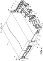
- FIG. 4 is a diagram showing a cable management assembly 20 applied to a rack system according to an embodiment of the present invention.
- the rack system comprises a first slide rail assembly 22 and a second slide rail assembly 23.
- the pair of slide rail assemblies 22, 23 is configured to mount a carried object 24 to a rack 26.
- the rack 26 comprises a pair of first posts 28a and a pair of second posts 28b.
- Each of the slide rail assemblies 22, 23 comprises a first rail 30 and a second rail 32 movable relative to the first rail 30.
- each of the slide rail assemblies 22, 23 further comprises a third rail 33 movably mounted between the first rail 30 and the second rail 32 for extending a travelling distance of the second rail 32 relative to the first rail 30.
- first rail 30 can be mounted to the first post 28a and the second post 28b through a first bracket 34 and a second bracket 36 respectively.
- second rail 32 is configured to carry the carried object 24.
- the carried object 24 is an electronic apparatus.
- the cable management assembly 20 further comprises a supporting device 38.
- the cable management assembly 20 comprises at least one arm and at least one cable management device.
- the cable management assembly 20 comprises a first arm 40, a second arm 42 and a plurality of cable management devices 44 connected to the first arm 40 and the second arm 42.
- the first arm 40 the second arm 42 are pivoted relative to each other.
- An end of the first arm 40 is connected to the first rail 30 of the first slide rail assembly 22, and an end of the second arm 42 is connected to the second rail 32 of the first slide rail assembly 22.
- the supporting device 38 is mounted between the first slide rail assembly 22 (such as the third rail 33 of the first slide rail assembly 22) and the second slide rail assembly 23 (such as the first rail 30 of the second slide rail assembly 23).
- the supporting device 38 is configured to support the cable management assembly 20.
- the supporting device 38 comprises a first supporting member 46 and a second supporting member 48 movable relative to the first supporting member 46.
- the second supporting member 48 is telescopically connected to the first supporting member 46.
- each of the cable management devices 44 comprises a first component 50 and a second component 52.
- the first component 50 and the second component 52 are made of a flexible material, such as a plastic or metal material.
- the first component 50 is a base and the second component 52 is a cover.
- the second component 52 can be opened or closed relative to the first component 50.
- a cable management space S is defined by the first component 50 and the second component 52.
- the cable management space S is configured to accommodate cables (not shown in figures) of the carried object 24.
- the function of the cable management device is well known to those skilled in the art. Therefore, no further illustration is provided.
- the first component 50 comprises a wall 54.
- the first component 50 further comprises a bottom part 56 and a connection part 58.
- Each of the wall 54 and the connection part 58 is bent relative to the bottom part 56 to from a predetermined angle therebetween.
- the wall 54, the bottom part 56 and the connection part 58 can form a U-shaped structure.
- the shape the first component 50 is illustrated as an example, the present invention is not limited thereto.
- Each of the cable management devices 44 is connected (such as engaged) with the first arm 40 or the second arm 42 through a plurality of engaging features arranged on the connection part 58 of the first component 50.
- the second component 52 is pivoted relative to the first component 50.
- the second component 52 is pivoted to the connection part 58 of the first component 50 by a shaft 60.
- the second component 52 comprises a first part 62 and a second part 64.
- the second part 64 is bent relative to the first part 62 and extended toward the bottom part 56.
- the second component 52 further comprises at least one auxiliary part 66.
- the second component 52 further comprises two auxiliary parts 66 arranged on the first part 62.
- the two auxiliary parts 66 are protruded from the first part 62 and extended toward the bottom part 56.
- a protrusion direction of the two auxiliary parts 66 relative to the first part 62 is substantially identical to a bending direction of the second part 64 relative to the first part 62.
- the wall 54 of the first component 50 of the cable management device 44 has a first side 68a and a second side 68b.
- the second side 68b is opposite to the first side 68a.
- the auxiliary part 66 comprises a first guiding section 70.
- the first guiding section 70 has an inclined surface or a curved surface.
- the first side 68a of the wall 54 of the first component 50 is formed with a first engagement part 72.
- the second component 52 comprises a second engagement part 74.
- the second engagement part 74 is arranged on the second part 64 of the second component 52.
- at least one of the first component 50 and the second component 52 has a second guiding section 76.
- each of the first engagement part 72 of the first component 50 and the second engagement part 74 of the second component 52 has the second guiding section 76.
- the second guiding section 76 has an inclined surface or a curved surface.
- the second engagement part 74 of the second component 52 is guided by the two second guiding sections 76 to be engaged with the first engagement part 72 of the first component 50.
- the first guiding section 70 of the auxiliary part 66 of the second component 52 contacts the second side 68b of the wall 54 of the first component 50such that the first guiding section 70 can provide a guiding effect during the process of closing the second component 52 relative to the first component 50.
- the second engagement part 74 of the second component 52 is engaged with the first engagement part 72 of the first component 50, and the auxiliary part 66 is located adjacent and corresponding to the second side 68b of the wall 54 of the first component 50.
- the wall 54 of the first component 50 is engaged between two portions (such as the second engagement part 74 and the auxiliary part 66) of the second component 52.
- arrangement of the auxiliary part 64 of the second component 52 can prevent the first engagement part 72 and the second engagement part 74 from being freely (or unintentionally) disengaged from each other due to the wall 54 of the first component 50 being pressed by a force F inwardly.
- a first distance L1 is defined between the auxiliary part 66 and the second side 68b of the wall 54 of the first component 50.
- a second distance L2 (such as an engagement distance) is defined between a front end of the first engagement part 72 and a front end the second engagement part 74.
- the first distance L1 is smaller than the second distance L2.
- the wall 54 of the first component 50 when the wall 54 of the first component 50 is pressed by the force F inwardly, the wall can be flexibly bent inwardly only within the first distance L1 due to blocking of the auxiliary part 66, such that a movable distance of the first engagement part 72 relative to the second engagement part 74 is smaller than the second distance L2. Therefore, the first engagement part 72 can be prevented from being disengaged from the second engagement part 74.
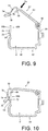
- a user in order to disengage the second component part 74 from the first engagement part 72, a user can open the second component 52 relative to the first component 50 along a second direction D2, so as to allow the second component 52 to be in an opened state relative to the first component 50 (refer to FIG. 9 ) for mounting or moving out the cables of the carried object 24.
Landscapes
- Engineering & Computer Science (AREA)
- General Engineering & Computer Science (AREA)
- Microelectronics & Electronic Packaging (AREA)
- Computer Hardware Design (AREA)
- Mechanical Engineering (AREA)
- Architecture (AREA)
- Civil Engineering (AREA)
- Structural Engineering (AREA)
- Insertion, Bundling And Securing Of Wires For Electric Apparatuses (AREA)
- Installation Of Indoor Wiring (AREA)
- Supports For Pipes And Cables (AREA)
- Details Of Indoor Wiring (AREA)
Abstract
Description
- The present invention is related to a cable management assembly and a cable management device thereof.
- Generally, a cable management assembly is usually used in a rack system. In particular, the rack system comprises a pair of slide rail assemblies mounted to a plurality of posts of a rack. A rail of the slide rail assembly is configured to carry an electronic apparatus, such as a server. The cable management assembly is configured to hold or accommodate cables of the electronic apparatus, in order to allow the cables to remain organized when the electronic apparatus is moved relative to the rack through the rail.
-
US patent number 7,554,819 B2 discloses a cable management arm assembly.FIG. 1 of the case shows the cable management arm assembly comprising a front arm (11) and a rear arm (12) pivoted relative to the front arm (11). As shown inFIG. 14 and FIG. 15 of the case, an end of the rear arm (12) is mounted to an outer rail (A) of a slide rail assembly, and an end of the front arm (11) is mounted to an inner rail (C) of the slide rail assembly, such that the front arm (11) and the rear arm (12) can be retracted or expanded in response to movement of the inner rail (C) relative to the outer rail (A) . Wherein, a plurality of cable holders (15) are arranged on each of the arms (11, 12) of the slide rail assembly for holding or accommodating the cables. The case is provided for reference. -
FIG. 1 is a diagram showing a cable holder of the prior art. Specifically, the cable holder comprises acable base 100 and acover 102. Thecable base 100 has awall 105, and thewall 105 has afirst engagement part 106. On the other hand, thecover 102 has asecond engagement part 104. When thecover 102 is in a closed state relative to thecable base 100, thesecond engagement part 104 is engaged with thefirst engagement part 106. However, as shown inFIG. 2 , in the closed state, when a force F is applied to thewall 105 of thecable base 100 inwardly, thefirst engagement part 106 may be detached from thesecond engagement 104. Accordingly, as shown inFIG. 3 , thecover 102 can be freely opened relative to thecable base 100 along a direction D. - Therefore, for different operating conditions and different market requirements, it is necessary to develop different products to meet specific requirements.
- This in mind, the present invention aims at providing a cable management assembly and a cable management device.
- This is achieved by a cable management device according to
claim 1, and a cable management assembly according to claims 8 and 10. The dependent claims pertain to corresponding further developments and improvements. - As will be seen more clearly from the detailed description following below, the claimed cable management device comprises a first component and a second component. The first component comprises a bottom part and a wall bent relative to the bottom part. The second component is configured to be opened or closed relative to the first component. The second component comprises two portions corresponding to the wall and extended toward the bottom part. Wherein, when the second component is closed relative to the first component, a cable management space is defined by the first component and the second component, and the wall of the first component is engaged between the two portions of the second component.
- As will be seen more clearly from the detailed description following below, the claimed cable management assembly comprises an arm and a cable management device. The cable management device is arranged on the arm. The cable management device comprises a first component and a second component. The first component comprises a wall. The wall has a first side and a second side. The first side is formed with a first engagement part. The second component is configured to be opened or closed relative to the first component. The second component comprises a second engagement part and an auxiliary part. When the second component is closed relative to the first component, the second engagement part is engaged with the first engagement part of the first component, and the auxiliary part is located adjacent to the second side of the wall of the first component.
- As will be seen more clearly from the detailed description following below, the claimed cable management assembly is applicable to a rack system. The rack system comprises a pair of slide rail assemblies for mounting a carried object to a rack. Each of the slide rail assemblies comprises a first rail and a second rail movable relative to the first rail. The first rail is configured to be mounted to a pair of posts of the rack. The second rail is configured to carry the carried object. The cable management assembly comprises two arms and a plurality of cable management devices. The two arms are pivoted to each other. The plurality of cable management devices are arranged on the two arms. Each of the cable management devices comprises a first component and a second component. The first component comprises a bottom part and a wall bent relative to the bottom part. The second component is configured to be opened or closed relative to the first component. The second component comprises two portions corresponding to the wall and extended toward the bottom part. When the second component is closed relative to the first component, the wall of the first component is engaged between the two portions of the second component.
- In the following, the invention is further illustrated by way of example, taking reference to the accompanying drawings thereof:
-
FIG. 1 is a diagram showing a cable holder of the prior art, wherein a cover of the cable holder is engaged with a cable base, and the cover is in a closed state relative to the cable base; -
FIG. 2 is a diagram showing a wall of the cable base of the cable holder of the prior art being pushed by a force, and the cover being disengaged from the cable base; -
FIG. 3 is a diagram showing the cover being opened relative to the cable base after the cover is disengaged from the cable base; -
FIG. 4 is a diagram showing a cable management assembly applied to a rack system according to an embodiment of the present invention; -
FIG. 5 is an exploded view of the cable management assembly and a slide rail assembly according to an embodiment of the present invention; -
FIG. 6 is an exploded view of a cable management device according to an embodiment of the present invention; -
FIG. 7 is a diagram showing the cable management device according to an embodiment of the present invention; -
FIG. 8 is a diagram showing the cable management device ofFIG. 7 in another angle; -
FIG. 9 is a diagram showing the cable management device in an opened state according to an embodiment of the present invention; -
FIG. 10 is a diagram showing the cable management device ofFIG. 9 being gradually closed from the opened state; -
FIG. 11 is a diagram showing the cable management device ofFIG. 10 being in a closed state; -
FIG. 12 is an enlarged view of an area A ofFIG. 11 ; -
FIG. 13 is an enlarged view of an area B ofFIG. 11 ; and -
FIG. 14 is a diagram showing the cable management device being gradually opened form the closed state according to an embodiment of the present invention. -
FIG. 4 is a diagram showing acable management assembly 20 applied to a rack system according to an embodiment of the present invention. The rack system comprises a firstslide rail assembly 22 and a secondslide rail assembly 23. The pair ofslide rail assemblies object 24 to arack 26. Wherein, therack 26 comprises a pair offirst posts 28a and a pair ofsecond posts 28b. Each of theslide rail assemblies first rail 30 and asecond rail 32 movable relative to thefirst rail 30. Preferably, each of theslide rail assemblies third rail 33 movably mounted between thefirst rail 30 and thesecond rail 32 for extending a travelling distance of thesecond rail 32 relative to thefirst rail 30. In particular, thefirst rail 30 can be mounted to thefirst post 28a and thesecond post 28b through afirst bracket 34 and asecond bracket 36 respectively. On the other hand, thesecond rail 32 is configured to carry the carriedobject 24. In the present embodiment, the carriedobject 24 is an electronic apparatus. Preferably, thecable management assembly 20 further comprises a supportingdevice 38. - As shown in
FIG. 5 , thecable management assembly 20 comprises at least one arm and at least one cable management device. In the present embodiment, thecable management assembly 20 comprises afirst arm 40, asecond arm 42 and a plurality ofcable management devices 44 connected to thefirst arm 40 and thesecond arm 42. In particular, thefirst arm 40 thesecond arm 42 are pivoted relative to each other. An end of thefirst arm 40 is connected to thefirst rail 30 of the firstslide rail assembly 22, and an end of thesecond arm 42 is connected to thesecond rail 32 of the firstslide rail assembly 22. On the other hand, the supportingdevice 38 is mounted between the first slide rail assembly 22 (such as thethird rail 33 of the first slide rail assembly 22) and the second slide rail assembly 23 (such as thefirst rail 30 of the second slide rail assembly 23). The supportingdevice 38 is configured to support thecable management assembly 20. The supportingdevice 38 comprises a first supportingmember 46 and a second supportingmember 48 movable relative to the first supportingmember 46. For example, the second supportingmember 48 is telescopically connected to the first supportingmember 46. - As shown in
FIG. 6 and FIG. 7 , each of thecable management devices 44 comprises afirst component 50 and asecond component 52. Preferably, thefirst component 50 and thesecond component 52 are made of a flexible material, such as a plastic or metal material. In the present embodiment, thefirst component 50 is a base and thesecond component 52 is a cover. Thesecond component 52 can be opened or closed relative to thefirst component 50. When thesecond component 52 is closed relative to thefirst component 50, a cable management space S is defined by thefirst component 50 and thesecond component 52. The cable management space S is configured to accommodate cables (not shown in figures) of the carriedobject 24. The function of the cable management device is well known to those skilled in the art. Therefore, no further illustration is provided. - The
first component 50 comprises awall 54. In the present embodiment, thefirst component 50 further comprises abottom part 56 and aconnection part 58. Each of thewall 54 and theconnection part 58 is bent relative to thebottom part 56 to from a predetermined angle therebetween. In particular, thewall 54, thebottom part 56 and theconnection part 58 can form a U-shaped structure. The shape thefirst component 50 is illustrated as an example, the present invention is not limited thereto. Each of thecable management devices 44 is connected (such as engaged) with thefirst arm 40 or thesecond arm 42 through a plurality of engaging features arranged on theconnection part 58 of thefirst component 50. - The
second component 52 is pivoted relative to thefirst component 50. For example, thesecond component 52 is pivoted to theconnection part 58 of thefirst component 50 by ashaft 60. - As shown in
FIG. 8 , thesecond component 52 comprises afirst part 62 and asecond part 64. Preferably, thesecond part 64 is bent relative to thefirst part 62 and extended toward thebottom part 56. Wherein, thesecond component 52 further comprises at least oneauxiliary part 66. In the present embodiment, thesecond component 52 further comprises twoauxiliary parts 66 arranged on thefirst part 62. Wherein, the twoauxiliary parts 66 are protruded from thefirst part 62 and extended toward thebottom part 56. A protrusion direction of the twoauxiliary parts 66 relative to thefirst part 62 is substantially identical to a bending direction of thesecond part 64 relative to thefirst part 62. - As shown in
FIG. 9 , thewall 54 of thefirst component 50 of thecable management device 44 has afirst side 68a and asecond side 68b. Preferably, thesecond side 68b is opposite to thefirst side 68a. Preferably, theauxiliary part 66 comprises afirst guiding section 70. Thefirst guiding section 70 has an inclined surface or a curved surface. On the other hand, thefirst side 68a of thewall 54 of thefirst component 50 is formed with afirst engagement part 72. Thesecond component 52 comprises asecond engagement part 74. Thesecond engagement part 74 is arranged on thesecond part 64 of thesecond component 52. Preferably, at least one of thefirst component 50 and thesecond component 52 has asecond guiding section 76. In the present embodiment, each of thefirst engagement part 72 of thefirst component 50 and thesecond engagement part 74 of thesecond component 52 has thesecond guiding section 76. Wherein, thesecond guiding section 76 has an inclined surface or a curved surface. - As shown in
FIG. 9 to FIG. 11 , during a process of closing thesecond component 52 relative to thefirst component 50 along a first direction D1, thesecond engagement part 74 of thesecond component 52 is guided by the twosecond guiding sections 76 to be engaged with thefirst engagement part 72 of thefirst component 50. On the other hand, thefirst guiding section 70 of theauxiliary part 66 of thesecond component 52 contacts thesecond side 68b of thewall 54 of the first component 50such that thefirst guiding section 70 can provide a guiding effect during the process of closing thesecond component 52 relative to thefirst component 50. - As shown in
FIG. 11 , when thesecond component 52 is in a closed state relative to thefirst component 50, thesecond engagement part 74 of thesecond component 52 is engaged with thefirst engagement part 72 of thefirst component 50, and theauxiliary part 66 is located adjacent and corresponding to thesecond side 68b of thewall 54 of thefirst component 50. Specifically, in the closed state, thewall 54 of thefirst component 50 is engaged between two portions (such as thesecond engagement part 74 and the auxiliary part 66) of thesecond component 52. In other words, arrangement of theauxiliary part 64 of thesecond component 52 can prevent thefirst engagement part 72 and thesecond engagement part 74 from being freely (or unintentionally) disengaged from each other due to thewall 54 of thefirst component 50 being pressed by a force F inwardly. - As shown in
FIG. 12 and FIG. 13 , when thesecond component 52 is in the closed state relative to thefirst component 50, a first distance L1 is defined between theauxiliary part 66 and thesecond side 68b of thewall 54 of thefirst component 50. On the other hand, a second distance L2 (such as an engagement distance) is defined between a front end of thefirst engagement part 72 and a front end thesecond engagement part 74. Wherein, the first distance L1 is smaller than the second distance L2. That is to say, when thewall 54 of thefirst component 50 is pressed by the force F inwardly, the wall can be flexibly bent inwardly only within the first distance L1 due to blocking of theauxiliary part 66, such that a movable distance of thefirst engagement part 72 relative to thesecond engagement part 74 is smaller than the second distance L2. Therefore, thefirst engagement part 72 can be prevented from being disengaged from thesecond engagement part 74. - As shown in
FIG. 14 , in order to disengage thesecond component part 74 from thefirst engagement part 72, a user can open thesecond component 52 relative to thefirst component 50 along a second direction D2, so as to allow thesecond component 52 to be in an opened state relative to the first component 50 (refer toFIG. 9 ) for mounting or moving out the cables of the carriedobject 24. - Those skilled in the art will readily observe that numerous modifications and alterations of the device and method may be made while retaining the teachings of the invention. Accordingly, the above disclosure should be construed as limited only by the metes and bounds of the appended claims.
Claims (10)
- A cable management device (44), comprising:a first component (50) comprising a bottom part (56) and a wall (54) bent relative to the bottom part (56); and characterized by:a second component (52) configured to be opened or closed relative to the first component (50), the second component (52) comprising two portions corresponding to the wall (54) and extended toward the bottom part (56);wherein when the second component (52) is closed relative to the first component (50), a cable management space is defined by the first component (50) and the second component (52), and the wall (54) of the first component (50) is engaged between the two portions of the second component (52).
- The cable management device of claim 1, characterized in that the wall (54) of the first component (50) has a first side (68a) and a second side (68b), the first side (68a) is formed with a first engagement part (72), the two portions of the second component (52) are a second engagement part (74) and an auxiliary part (66) respectively; wherein when the second component (52) is closed relative to the first component (50), the second engagement part (74) is engaged with the first engagement part (72) of the first component (50), and the auxiliary part (66) is located adjacent to the second side (68b) of the wall (54) of the first component (50).
- The cable management device of claim 2, characterized in that the second side (68b) of the wall (54) of the first component (50) is opposite to the first side (68a).
- The cable management device of any of claims 1-3, characterized in that the second component (52) is pivoted relative to the first component (50).
- The cable management device of claim 2 or 3, characterized in that the auxiliary part (66) comprises a first guiding section (70), during a process of closing the second component (52) relative to the first component (50), the first guiding section (70) contacts the wall (54) of the first component (50).
- The cable management device of claim 5, characterized in that the first guiding section (70) has an inclined surface or a curved surface.
- The cable management device of claim 5 or 6, characterized in that one of the first component (50) and the second component (52) has a second guiding section (76) for guiding the second engagement part (74) of the second component (52) to be engaged with the first engagement part (72) of the first component (50) during the process of closing the second component (52) relative to the first component (50), the second guiding section (76) has an inclined surface or a curved surface.
- A cable management assembly (20), comprising:an arm (40, 42); anda cable management device (44) arranged on the arm (40, 42), the cable management device (44) comprising:a first component (50) comprising a wall (54), the wall (54) having a first side (68a) and a second side (68b), the first side (68a) being formed with a first engagement part (72); andcharacterized by:a second component (52) configured to be opened or closed relative to the first component (50), the second component (52) comprising a second engagement part (74) and an auxiliary part (66), wherein when the second component (52) is closed relative to the first component (50), the second engagement part (74) is engaged with the first engagement part (72) of the first component (50), and the auxiliary part (66) is located adjacent to the second side (68b) of the wall (54) of the first component (50).
- The cable management assembly of claim 8, characterized in that the second side (68b) of the wall (54) of the first component (50) is opposite to the first side (68a).
- A cable management assembly (20), applicable to a rack system, the rack system comprising a pair of slide rail assemblies (22, 23) for mounting a carried object (24) to a rack (26), each of the slide rail assemblies (22, 23) comprising a first rail (30) and a second rail (32) movable relative to the first rail (30), the first rail (30) being configured to be mounted to a pair of posts (28a, 28b) of the rack (26), the second rail (32) being configured to carry the carried object (24), the cable management assembly (20) comprising:two arms (40, 42) pivoted to each other; anda plurality of cable management devices (44) arranged on the two arms (40, 42), each of the cable management devices (44) comprising:a first component (50) comprising a bottom part (56) and a wall (54) bent relative to the bottom part (56); andcharacterized by:a second component (52) configured to be opened or closed relative to the first component (50), the second component (52) comprising two portions corresponding to the wall (54) and extended toward the bottom part (56), wherein when the second component (52) is closed relative to the first component (50), the wall (54) of the first component (50) is engaged between the two portions of the second component (52).
Applications Claiming Priority (1)
| Application Number | Priority Date | Filing Date | Title |
|---|---|---|---|
| TW105126011A TWI605328B (en) | 2016-08-12 | 2016-08-12 | Cable management assembly and cable management device thereof |
Publications (2)
| Publication Number | Publication Date |
|---|---|
| EP3282529A1 true EP3282529A1 (en) | 2018-02-14 |
| EP3282529B1 EP3282529B1 (en) | 2021-07-14 |
Family
ID=57794147
Family Applications (1)
| Application Number | Title | Priority Date | Filing Date |
|---|---|---|---|
| EP17150926.8A Active EP3282529B1 (en) | 2016-08-12 | 2017-01-11 | Cable management assembly and cable management device thereof |
Country Status (4)
| Country | Link |
|---|---|
| US (1) | US9913398B1 (en) |
| EP (1) | EP3282529B1 (en) |
| JP (2) | JP2018026999A (en) |
| TW (1) | TWI605328B (en) |
Families Citing this family (12)
| Publication number | Priority date | Publication date | Assignee | Title |
|---|---|---|---|---|
| JP6943750B2 (en) * | 2017-12-19 | 2021-10-06 | 日本通信電材株式会社 | Cord clamp |
| TWI644607B (en) * | 2018-04-20 | 2018-12-11 | 川湖科技股份有限公司 | Rack system and cable supporting assembly thereof |
| US10606011B2 (en) * | 2018-06-20 | 2020-03-31 | Panduit Corp. | Universal expandable cable management bracket |
| TWI677275B (en) * | 2018-08-20 | 2019-11-11 | 川湖科技股份有限公司 | Coupling assembly and cable management device thereof |
| TWI681703B (en) * | 2019-02-25 | 2020-01-01 | 川湖科技股份有限公司 | Slide rail mechanism and supporting assembly thereof |
| TWI684396B (en) * | 2019-02-25 | 2020-02-01 | 川湖科技股份有限公司 | Slide rail mechanism and supporting assembly thereof |
| TWI698164B (en) * | 2019-06-25 | 2020-07-01 | 川湖科技股份有限公司 | Cable management assembly |
| TWI705636B (en) | 2019-09-04 | 2020-09-21 | 川湖科技股份有限公司 | Coupling assembly and cable management device thereof |
| US11248723B2 (en) * | 2019-10-16 | 2022-02-15 | Hewlett Packard Enterprise Development Lp | Cable management arm basket clip |
| TWI706708B (en) * | 2019-10-18 | 2020-10-01 | 川湖科技股份有限公司 | Cable management assembly |
| CN112714578B (en) * | 2019-10-25 | 2022-03-01 | 川湖科技股份有限公司 | Wire management assembly |
| US11251593B2 (en) * | 2019-11-04 | 2022-02-15 | Cisco Technology, Inc. | Minimal touch post for multi-layer cable routing |
Citations (4)
| Publication number | Priority date | Publication date | Assignee | Title |
|---|---|---|---|---|
| FR2383539A1 (en) * | 1977-03-09 | 1978-10-06 | Legrand Sa | Cable conduit with demountable cover plate - has tongue and groove interlock on its inside surface which can be disengaged by screwdriver |
| US20050115739A1 (en) * | 2003-10-28 | 2005-06-02 | Actuant Corporation | Cable holder |
| US20060113433A1 (en) * | 2004-10-15 | 2006-06-01 | Ken-Ching Chen | Cable management arm assembly |
| US8157222B1 (en) * | 2010-10-29 | 2012-04-17 | Toyota Motor Engineering & Manufacturing North America, Inc. | Wire harness clamp |
Family Cites Families (15)
| Publication number | Priority date | Publication date | Assignee | Title |
|---|---|---|---|---|
| US4609171A (en) * | 1983-09-05 | 1986-09-02 | Kitagawa Industries Co., Ltd. | Electric wire bundle clamp |
| JP2583435Y2 (en) | 1993-10-23 | 1998-10-22 | 古河電気工業株式会社 | Wire harness protector |
| JPH09144718A (en) | 1995-11-24 | 1997-06-03 | Yazaki Corp | Locking structure |
| DE19934705A1 (en) * | 1998-08-17 | 2000-02-24 | Henkel Kgaa | Packaging adhesives in a container with an opening used for cohesive adhesives uses a container that retains its shape below 50 degrees |
| TWI276276B (en) * | 2005-04-19 | 2007-03-11 | King Slide Works Co Ltd | Cable management arm assembly |
| US7654398B2 (en) * | 2005-07-19 | 2010-02-02 | International Business Machines Corporation | Cable management system with adjustable length arm |
| CN201263269Y (en) * | 2008-08-15 | 2009-06-24 | 鸿富锦精密工业(深圳)有限公司 | cable management rack |
| TW201128889A (en) * | 2010-02-03 | 2011-08-16 | Dan Chief Entpr Co Ltd | Device of patch panel and method for manipulating the same |
| US8634198B2 (en) | 2011-07-01 | 2014-01-21 | King Slide Works Co., Ltd. | Connection device of cable management arm |
| TWI446666B (en) * | 2011-12-23 | 2014-07-21 | King Slide Works Co Ltd | Connecting device of a cable management arm |
| US9072190B2 (en) | 2012-12-07 | 2015-06-30 | King Slide Works Co., Ltd. | Cable management arm |
| US20150342081A1 (en) * | 2014-05-22 | 2015-11-26 | Nan Juen International Co., Ltd. | Case cable organizer structure |
| TWI524615B (en) * | 2014-09-19 | 2016-03-01 | 川湖科技股份有限公司 | Support device for cable management arm and mounting assembly thereof |
| US9383038B2 (en) * | 2014-12-04 | 2016-07-05 | King Slide Works Co., Ltd. | Cable management arm supporting device and mounting assembly thereof |
| TWI556712B (en) | 2015-05-05 | 2016-11-01 | King Slide Works Co Ltd | Cable management assembly |
-
2016
- 2016-08-12 TW TW105126011A patent/TWI605328B/en active
- 2016-11-24 US US15/361,069 patent/US9913398B1/en active Active
- 2016-12-08 JP JP2016238093A patent/JP2018026999A/en active Pending
-
2017
- 2017-01-11 EP EP17150926.8A patent/EP3282529B1/en active Active
-
2018
- 2018-10-01 JP JP2018186467A patent/JP6734339B2/en active Active
Patent Citations (5)
| Publication number | Priority date | Publication date | Assignee | Title |
|---|---|---|---|---|
| FR2383539A1 (en) * | 1977-03-09 | 1978-10-06 | Legrand Sa | Cable conduit with demountable cover plate - has tongue and groove interlock on its inside surface which can be disengaged by screwdriver |
| US20050115739A1 (en) * | 2003-10-28 | 2005-06-02 | Actuant Corporation | Cable holder |
| US20060113433A1 (en) * | 2004-10-15 | 2006-06-01 | Ken-Ching Chen | Cable management arm assembly |
| US7554819B2 (en) | 2004-10-15 | 2009-06-30 | King Slide Works Co., Ltd. | Cable management arm assembly |
| US8157222B1 (en) * | 2010-10-29 | 2012-04-17 | Toyota Motor Engineering & Manufacturing North America, Inc. | Wire harness clamp |
Also Published As
| Publication number | Publication date |
|---|---|
| JP2018026999A (en) | 2018-02-15 |
| US20180049341A1 (en) | 2018-02-15 |
| TW201809953A (en) | 2018-03-16 |
| US9913398B1 (en) | 2018-03-06 |
| EP3282529B1 (en) | 2021-07-14 |
| JP6734339B2 (en) | 2020-08-05 |
| TWI605328B (en) | 2017-11-11 |
| JP2019047724A (en) | 2019-03-22 |
Similar Documents
| Publication | Publication Date | Title |
|---|---|---|
| EP3282529B1 (en) | Cable management assembly and cable management device thereof | |
| EP3091823B1 (en) | Cable management assembly | |
| EP3154320B1 (en) | Slide rail assembly and bracket device thereof | |
| US9474182B1 (en) | Slide rail assembly | |
| EP3253189A1 (en) | Slide rail device | |
| US10292301B1 (en) | Coupling assembly and cable management device thereof | |
| EP3193569B1 (en) | Bracket device | |
| JP6817348B2 (en) | Connecting assembly and its cable management device | |
| US20190142158A1 (en) | Slide rail rack system and carried object thereof | |
| EP3324094A1 (en) | Portable device holder for vehicle cd-slot mounting | |
| EP3422830A1 (en) | Connecting assembly for rack system | |
| EP3282713A1 (en) | Slide rail assembly and cable management device thereof | |
| EP3273757B1 (en) | Slide rail assembly for rack system | |
| EP3440961A1 (en) | Slide rail assembly and rail kit thereof | |
| US9635942B2 (en) | Slide rail assembly | |
| EP3700311A1 (en) | Slide rail mechanism and supporting assembly thereof | |
| CN110406478A (en) | Display device retainer | |
| JP6268006B2 (en) | Harness equipment | |
| EP3351346B1 (en) | Fixing device | |
| EP3136694B1 (en) | Housing mounting mechanism for portable electronic device | |
| EP3700310B1 (en) | Slide rail mechanism and supporting assembly thereof | |
| EP3166374A2 (en) | Slide rail assembly | |
| CN107770993A (en) | Wire arranging assembly and wire arranging device thereof | |
| EP3116291A1 (en) | Slide rail mounting mechanism | |
| EP3076773B1 (en) | Slide rail assembly |
Legal Events
| Date | Code | Title | Description |
|---|---|---|---|
| PUAI | Public reference made under article 153(3) epc to a published international application that has entered the european phase |
Free format text: ORIGINAL CODE: 0009012 |
|
| STAA | Information on the status of an ep patent application or granted ep patent |
Free format text: STATUS: THE APPLICATION HAS BEEN PUBLISHED |
|
| AK | Designated contracting states |
Kind code of ref document: A1 Designated state(s): AL AT BE BG CH CY CZ DE DK EE ES FI FR GB GR HR HU IE IS IT LI LT LU LV MC MK MT NL NO PL PT RO RS SE SI SK SM TR |
|
| AX | Request for extension of the european patent |
Extension state: BA ME |
|
| STAA | Information on the status of an ep patent application or granted ep patent |
Free format text: STATUS: REQUEST FOR EXAMINATION WAS MADE |
|
| 17P | Request for examination filed |
Effective date: 20180802 |
|
| RBV | Designated contracting states (corrected) |
Designated state(s): AL AT BE BG CH CY CZ DE DK EE ES FI FR GB GR HR HU IE IS IT LI LT LU LV MC MK MT NL NO PL PT RO RS SE SI SK SM TR |
|
| STAA | Information on the status of an ep patent application or granted ep patent |
Free format text: STATUS: EXAMINATION IS IN PROGRESS |
|
| 17Q | First examination report despatched |
Effective date: 20200206 |
|
| GRAP | Despatch of communication of intention to grant a patent |
Free format text: ORIGINAL CODE: EPIDOSNIGR1 |
|
| STAA | Information on the status of an ep patent application or granted ep patent |
Free format text: STATUS: GRANT OF PATENT IS INTENDED |
|
| INTG | Intention to grant announced |
Effective date: 20210112 |
|
| INTG | Intention to grant announced |
Effective date: 20210113 |
|
| GRAS | Grant fee paid |
Free format text: ORIGINAL CODE: EPIDOSNIGR3 |
|
| GRAA | (expected) grant |
Free format text: ORIGINAL CODE: 0009210 |
|
| STAA | Information on the status of an ep patent application or granted ep patent |
Free format text: STATUS: THE PATENT HAS BEEN GRANTED |
|
| AK | Designated contracting states |
Kind code of ref document: B1 Designated state(s): AL AT BE BG CH CY CZ DE DK EE ES FI FR GB GR HR HU IE IS IT LI LT LU LV MC MK MT NL NO PL PT RO RS SE SI SK SM TR |
|
| REG | Reference to a national code |
Ref country code: GB Ref legal event code: FG4D |
|
| REG | Reference to a national code |
Ref country code: IE Ref legal event code: FG4D |
|
| REG | Reference to a national code |
Ref country code: DE Ref legal event code: R096 Ref document number: 602017041968 Country of ref document: DE |
|
| REG | Reference to a national code |
Ref country code: AT Ref legal event code: REF Ref document number: 1411395 Country of ref document: AT Kind code of ref document: T Effective date: 20210815 |
|
| REG | Reference to a national code |
Ref country code: LT Ref legal event code: MG9D |
|
| REG | Reference to a national code |
Ref country code: NL Ref legal event code: MP Effective date: 20210714 |
|
| REG | Reference to a national code |
Ref country code: AT Ref legal event code: MK05 Ref document number: 1411395 Country of ref document: AT Kind code of ref document: T Effective date: 20210714 |
|
| PG25 | Lapsed in a contracting state [announced via postgrant information from national office to epo] |
Ref country code: LT Free format text: LAPSE BECAUSE OF FAILURE TO SUBMIT A TRANSLATION OF THE DESCRIPTION OR TO PAY THE FEE WITHIN THE PRESCRIBED TIME-LIMIT Effective date: 20210714 Ref country code: BG Free format text: LAPSE BECAUSE OF FAILURE TO SUBMIT A TRANSLATION OF THE DESCRIPTION OR TO PAY THE FEE WITHIN THE PRESCRIBED TIME-LIMIT Effective date: 20211014 Ref country code: AT Free format text: LAPSE BECAUSE OF FAILURE TO SUBMIT A TRANSLATION OF THE DESCRIPTION OR TO PAY THE FEE WITHIN THE PRESCRIBED TIME-LIMIT Effective date: 20210714 Ref country code: PT Free format text: LAPSE BECAUSE OF FAILURE TO SUBMIT A TRANSLATION OF THE DESCRIPTION OR TO PAY THE FEE WITHIN THE PRESCRIBED TIME-LIMIT Effective date: 20211115 Ref country code: NO Free format text: LAPSE BECAUSE OF FAILURE TO SUBMIT A TRANSLATION OF THE DESCRIPTION OR TO PAY THE FEE WITHIN THE PRESCRIBED TIME-LIMIT Effective date: 20211014 Ref country code: NL Free format text: LAPSE BECAUSE OF FAILURE TO SUBMIT A TRANSLATION OF THE DESCRIPTION OR TO PAY THE FEE WITHIN THE PRESCRIBED TIME-LIMIT Effective date: 20210714 Ref country code: FI Free format text: LAPSE BECAUSE OF FAILURE TO SUBMIT A TRANSLATION OF THE DESCRIPTION OR TO PAY THE FEE WITHIN THE PRESCRIBED TIME-LIMIT Effective date: 20210714 Ref country code: ES Free format text: LAPSE BECAUSE OF FAILURE TO SUBMIT A TRANSLATION OF THE DESCRIPTION OR TO PAY THE FEE WITHIN THE PRESCRIBED TIME-LIMIT Effective date: 20210714 Ref country code: HR Free format text: LAPSE BECAUSE OF FAILURE TO SUBMIT A TRANSLATION OF THE DESCRIPTION OR TO PAY THE FEE WITHIN THE PRESCRIBED TIME-LIMIT Effective date: 20210714 Ref country code: RS Free format text: LAPSE BECAUSE OF FAILURE TO SUBMIT A TRANSLATION OF THE DESCRIPTION OR TO PAY THE FEE WITHIN THE PRESCRIBED TIME-LIMIT Effective date: 20210714 Ref country code: SE Free format text: LAPSE BECAUSE OF FAILURE TO SUBMIT A TRANSLATION OF THE DESCRIPTION OR TO PAY THE FEE WITHIN THE PRESCRIBED TIME-LIMIT Effective date: 20210714 |
|
| PG25 | Lapsed in a contracting state [announced via postgrant information from national office to epo] |
Ref country code: PL Free format text: LAPSE BECAUSE OF FAILURE TO SUBMIT A TRANSLATION OF THE DESCRIPTION OR TO PAY THE FEE WITHIN THE PRESCRIBED TIME-LIMIT Effective date: 20210714 Ref country code: LV Free format text: LAPSE BECAUSE OF FAILURE TO SUBMIT A TRANSLATION OF THE DESCRIPTION OR TO PAY THE FEE WITHIN THE PRESCRIBED TIME-LIMIT Effective date: 20210714 Ref country code: GR Free format text: LAPSE BECAUSE OF FAILURE TO SUBMIT A TRANSLATION OF THE DESCRIPTION OR TO PAY THE FEE WITHIN THE PRESCRIBED TIME-LIMIT Effective date: 20211015 |
|
| REG | Reference to a national code |
Ref country code: DE Ref legal event code: R097 Ref document number: 602017041968 Country of ref document: DE |
|
| PG25 | Lapsed in a contracting state [announced via postgrant information from national office to epo] |
Ref country code: DK Free format text: LAPSE BECAUSE OF FAILURE TO SUBMIT A TRANSLATION OF THE DESCRIPTION OR TO PAY THE FEE WITHIN THE PRESCRIBED TIME-LIMIT Effective date: 20210714 |
|
| PLBE | No opposition filed within time limit |
Free format text: ORIGINAL CODE: 0009261 |
|
| STAA | Information on the status of an ep patent application or granted ep patent |
Free format text: STATUS: NO OPPOSITION FILED WITHIN TIME LIMIT |
|
| PG25 | Lapsed in a contracting state [announced via postgrant information from national office to epo] |
Ref country code: SM Free format text: LAPSE BECAUSE OF FAILURE TO SUBMIT A TRANSLATION OF THE DESCRIPTION OR TO PAY THE FEE WITHIN THE PRESCRIBED TIME-LIMIT Effective date: 20210714 Ref country code: SK Free format text: LAPSE BECAUSE OF FAILURE TO SUBMIT A TRANSLATION OF THE DESCRIPTION OR TO PAY THE FEE WITHIN THE PRESCRIBED TIME-LIMIT Effective date: 20210714 Ref country code: RO Free format text: LAPSE BECAUSE OF FAILURE TO SUBMIT A TRANSLATION OF THE DESCRIPTION OR TO PAY THE FEE WITHIN THE PRESCRIBED TIME-LIMIT Effective date: 20210714 Ref country code: EE Free format text: LAPSE BECAUSE OF FAILURE TO SUBMIT A TRANSLATION OF THE DESCRIPTION OR TO PAY THE FEE WITHIN THE PRESCRIBED TIME-LIMIT Effective date: 20210714 Ref country code: CZ Free format text: LAPSE BECAUSE OF FAILURE TO SUBMIT A TRANSLATION OF THE DESCRIPTION OR TO PAY THE FEE WITHIN THE PRESCRIBED TIME-LIMIT Effective date: 20210714 Ref country code: AL Free format text: LAPSE BECAUSE OF FAILURE TO SUBMIT A TRANSLATION OF THE DESCRIPTION OR TO PAY THE FEE WITHIN THE PRESCRIBED TIME-LIMIT Effective date: 20210714 |
|
| 26N | No opposition filed |
Effective date: 20220419 |
|
| PG25 | Lapsed in a contracting state [announced via postgrant information from national office to epo] |
Ref country code: IT Free format text: LAPSE BECAUSE OF FAILURE TO SUBMIT A TRANSLATION OF THE DESCRIPTION OR TO PAY THE FEE WITHIN THE PRESCRIBED TIME-LIMIT Effective date: 20210714 |
|
| PG25 | Lapsed in a contracting state [announced via postgrant information from national office to epo] |
Ref country code: MC Free format text: LAPSE BECAUSE OF FAILURE TO SUBMIT A TRANSLATION OF THE DESCRIPTION OR TO PAY THE FEE WITHIN THE PRESCRIBED TIME-LIMIT Effective date: 20210714 |
|
| REG | Reference to a national code |
Ref country code: CH Ref legal event code: PL |
|
| REG | Reference to a national code |
Ref country code: BE Ref legal event code: MM Effective date: 20220131 |
|
| PG25 | Lapsed in a contracting state [announced via postgrant information from national office to epo] |
Ref country code: LU Free format text: LAPSE BECAUSE OF NON-PAYMENT OF DUE FEES Effective date: 20220111 |
|
| PG25 | Lapsed in a contracting state [announced via postgrant information from national office to epo] |
Ref country code: FR Free format text: LAPSE BECAUSE OF NON-PAYMENT OF DUE FEES Effective date: 20220131 Ref country code: BE Free format text: LAPSE BECAUSE OF NON-PAYMENT OF DUE FEES Effective date: 20220131 |
|
| PG25 | Lapsed in a contracting state [announced via postgrant information from national office to epo] |
Ref country code: LI Free format text: LAPSE BECAUSE OF NON-PAYMENT OF DUE FEES Effective date: 20220131 Ref country code: CH Free format text: LAPSE BECAUSE OF NON-PAYMENT OF DUE FEES Effective date: 20220131 |
|
| PG25 | Lapsed in a contracting state [announced via postgrant information from national office to epo] |
Ref country code: HU Free format text: LAPSE BECAUSE OF FAILURE TO SUBMIT A TRANSLATION OF THE DESCRIPTION OR TO PAY THE FEE WITHIN THE PRESCRIBED TIME-LIMIT; INVALID AB INITIO Effective date: 20170111 |
|
| PG25 | Lapsed in a contracting state [announced via postgrant information from national office to epo] |
Ref country code: MK Free format text: LAPSE BECAUSE OF FAILURE TO SUBMIT A TRANSLATION OF THE DESCRIPTION OR TO PAY THE FEE WITHIN THE PRESCRIBED TIME-LIMIT Effective date: 20210714 Ref country code: CY Free format text: LAPSE BECAUSE OF FAILURE TO SUBMIT A TRANSLATION OF THE DESCRIPTION OR TO PAY THE FEE WITHIN THE PRESCRIBED TIME-LIMIT Effective date: 20210714 |
|
| PG25 | Lapsed in a contracting state [announced via postgrant information from national office to epo] |
Ref country code: TR Free format text: LAPSE BECAUSE OF FAILURE TO SUBMIT A TRANSLATION OF THE DESCRIPTION OR TO PAY THE FEE WITHIN THE PRESCRIBED TIME-LIMIT Effective date: 20210714 |
|
| REG | Reference to a national code |
Ref country code: DE Ref legal event code: R082 Ref document number: 602017041968 Country of ref document: DE Representative=s name: STRAUS, ALEXANDER, DIPL.-CHEM.UNIV. DR.PHIL., DE |
|
| PG25 | Lapsed in a contracting state [announced via postgrant information from national office to epo] |
Ref country code: MT Free format text: LAPSE BECAUSE OF FAILURE TO SUBMIT A TRANSLATION OF THE DESCRIPTION OR TO PAY THE FEE WITHIN THE PRESCRIBED TIME-LIMIT Effective date: 20210714 |
|
| PGFP | Annual fee paid to national office [announced via postgrant information from national office to epo] |
Ref country code: GB Payment date: 20251106 Year of fee payment: 10 |
|
| PGFP | Annual fee paid to national office [announced via postgrant information from national office to epo] |
Ref country code: IE Payment date: 20251106 Year of fee payment: 10 |
|
| PGFP | Annual fee paid to national office [announced via postgrant information from national office to epo] |
Ref country code: DE Payment date: 20251111 Year of fee payment: 10 |