EP3282142A1 - Wide-angle constant velocity joint - Google Patents
Wide-angle constant velocity joint Download PDFInfo
- Publication number
- EP3282142A1 EP3282142A1 EP16425085.4A EP16425085A EP3282142A1 EP 3282142 A1 EP3282142 A1 EP 3282142A1 EP 16425085 A EP16425085 A EP 16425085A EP 3282142 A1 EP3282142 A1 EP 3282142A1
- Authority
- EP
- European Patent Office
- Prior art keywords
- yoke
- joint
- wide
- axis
- pin
- Prior art date
- Legal status (The legal status is an assumption and is not a legal conclusion. Google has not performed a legal analysis and makes no representation as to the accuracy of the status listed.)
- Granted
Links
Images

Classifications
-
- F—MECHANICAL ENGINEERING; LIGHTING; HEATING; WEAPONS; BLASTING
- F16—ENGINEERING ELEMENTS AND UNITS; GENERAL MEASURES FOR PRODUCING AND MAINTAINING EFFECTIVE FUNCTIONING OF MACHINES OR INSTALLATIONS; THERMAL INSULATION IN GENERAL
- F16D—COUPLINGS FOR TRANSMITTING ROTATION; CLUTCHES; BRAKES
- F16D3/00—Yielding couplings, i.e. with means permitting movement between the connected parts during the drive
- F16D3/16—Universal joints in which flexibility is produced by means of pivots or sliding or rolling connecting parts
- F16D3/26—Hooke's joints or other joints with an equivalent intermediate member to which each coupling part is pivotally or slidably connected
- F16D3/30—Hooke's joints or other joints with an equivalent intermediate member to which each coupling part is pivotally or slidably connected in which the coupling is specially adapted to constant velocity-ratio
- F16D3/32—Hooke's joints or other joints with an equivalent intermediate member to which each coupling part is pivotally or slidably connected in which the coupling is specially adapted to constant velocity-ratio by the provision of two intermediate members each having two relatively perpendicular trunnions or bearings
Definitions
- the invention belongs to the field of mechanical power transmission systems, in particular of the transmission of the motion from a tractor where it is required that the transmission motion between the front yoke and the output yoke has a constant velocity, the angle between the two axes of the yokes reaching a maximum value of 25° in the work phases.
- Each of the swinging spherical bearings has two opposite spherical parts each swinging in a respective housing in the plate.
- Each of the opposite spherical bearings carries a through hole which works as a runway for the pin of the respective yoke and the variation of the angle between the yoke and the transverse axis of the joint, moves the centre of rotation of the joint, so that the pin of each yoke runs along said runway.
- the spherical bearings cause the contact pressure between the yoke and the plate to distribute on a large surface area and therefore break down the surface wear of the components.
- the wide-angle constant-velocity body OJ comprises two opposite yokes 1, 2 with inner flange and two opposite floating shims 3 between which there is a floating plate 8 bearing two opposite spherical bearings 11 each comprising two swinging spherical parts 11a mounted hot into corresponding housings 11b (or contact surfaces) obtained by a milling in the floating plate 8.
- the floating shims 3 can be fixed, housed in suitable locations.
- the instantaneous speed of the front yoke 9 for the input motion is equal to the instantaneous speed of the yoke 7 for the output motion once the angle ⁇ is equal to the angle ⁇ .
- the joint makes the angles ⁇ and ⁇ be constantly equal.
- the variation of said angles ( ⁇ , ⁇ ) causes the displacement of the centre of rotation (C) of the joint (OJ) which in turn causes the movement of the pin (10) of each yoke along the runaway (12) formed in the spherical bearings (11).
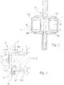
- Fig. 2 shows the floating plate 8 with its parts 11 and 11a and 11b with their housing surfaces suitable for receiving the spherical parts 11a.
- Fig. 3 shows the position of the yokes 7 and 9 with their pins 10 within their respective runways 12.
- the contact surface of the pin (10) with the runway (12) and the contact surface between the spherical parts (11a) and respective housings (11 b ) are maximized to reduce the wear of the surfaces, in particular the surface of each housing (11 b ) on which swings the spherical part (11 a ) is of 1.170 mm 2 .
Landscapes
- Engineering & Computer Science (AREA)
- General Engineering & Computer Science (AREA)
- Mechanical Engineering (AREA)
- Pivots And Pivotal Connections (AREA)
- Support Of The Bearing (AREA)
Abstract
Description
- The invention belongs to the field of mechanical power transmission systems, in particular of the transmission of the motion from a tractor where it is required that the transmission motion between the front yoke and the output yoke has a constant velocity, the angle between the two axes of the yokes reaching a maximum value of 25° in the work phases.
- There are several devices made by the applicant and third parties that perform the same function of transmitting the motion in different ways.
- For example, among the known documents there are the following two patents relating to the technical field of this application:
-
US 2002/0187840 A1 - Centred double universal joint, -
US 4,781,662 - Universal joint with improved lubrication. - In the wide-angle joints made in a standard configuration, at the top of the front yoke and of the out yoke, an integral ball, free to move along a runway, is obtained in a radial plate. During the rotation of the front yoke, through a contact point, it is caused the radial movement of the plate contained and held in place by a wide-angle body, the plate, in turn, acting on the ball of the out yoke causing a rotation equal to that of the front yoke. In this embodiment of the joint there is a high wear of the yoke and of the plate due to the high concentrated pressure on the point where the two components are in contact.
- The two cited patents overcome some drawbacks of the standard configuration in a manner different from that disclosed in the present application.
- The document closest to the application is
US 4,781,662 which provides a "ball joint" mounted on the yoke which causes a significant cost and a difficult construction. - The scope of a constant-velocity joint is to make equal the "input" and "output" instantaneous speeds of the yokes converging on the joint and to do this it is necessary that the angle between the front yoke and the joint axis be equal to the angle between the output yoke and the axis of the joint. In the wide angle constant-velocity joint conceived to the above purpose the feature is added to enable the system tractor- agricultural machine to achieve the desired angles.
- These objects are achieved by introducing, between two opposite yokes, a floating plate housing two opposite swinging spherical bearings, such an assembly allowing the two angles, the one between the axis of the front yoke and the transverse axis of the joint and the other between the axis of the out yoke and the transverse axis of the joint, to remain the same during the joint work.
- Each of the swinging spherical bearings has two opposite spherical parts each swinging in a respective housing in the plate.
- Each of the opposite spherical bearings carries a through hole which works as a runway for the pin of the respective yoke and the variation of the angle between the yoke and the transverse axis of the joint, moves the centre of rotation of the joint, so that the pin of each yoke runs along said runway.
- The spherical bearings cause the contact pressure between the yoke and the plate to distribute on a large surface area and therefore break down the surface wear of the components.
- Given that even the production process of the system components is optimized and therefore is cheaper than other manufacturing processes for equivalent joints, other advantages of the invention are shown in the following:
- a. The component - yoke with pin - on which the spherical part slides is economical, compact and robust.
- b. The component - plate with spherical bearings -, new feature in this field of the technique, is compact, simple to assemble and maintain and has a high useful life thanks to a better distribution of the pressures under variation of the working angles and to the maximization of the surfaces of contact between the parties.
- The invention will be described now by way of example of embodiment and the help of the drawing in which:
-
Fig. 1 is a first sectional view, the -
Fig. 2 is a second sectional view and -
Fig. 3 is a third sectional view. - With reference to
Fig. 1 , the wide-angle constant-velocity body OJ comprises two opposite yokes 1, 2 with inner flange and two opposite floatingshims 3 between which there is afloating plate 8 bearing two oppositespherical bearings 11 each comprising two swinging spherical parts 11a mounted hot intocorresponding housings 11b (or contact surfaces) obtained by a milling in thefloating plate 8. Alternatively, thefloating shims 3 can be fixed, housed in suitable locations. These opposite components become by welding a single assembly comprising thefloating plate 8 at its centre. - The instantaneous speed of the front yoke 9 for the input motion is equal to the instantaneous speed of the yoke 7 for the output motion once the angle α is equal to the angle β. The joint makes the angles α and β be constantly equal. The variation of said angles (α, β) causes the displacement of the centre of rotation (C) of the joint (OJ) which in turn causes the movement of the pin (10) of each yoke along the runaway (12) formed in the spherical bearings (11).
- It is understood that during the rotation of the yoke 9 of motion input, with the action of its
pin 10 on the spherical bearing, a radial movement of the floating plate is caused which, in turn, acts on thepin 10 of the motion output yoke 7 causing a rotation equal to that of the yoke 9 of the motion input. - The force required to change the working angle of the spherical bearing, acting on the output yoke 7 and transmitted from the
pin 10 to thefloating plate 8 and then to the input yoke 9, will be transmitted between different components through surfaces well-polished and oiled, and as wide as possible. -
Fig. 2 shows thefloating plate 8 with itsparts -
Fig. 3 shows the position of the yokes 7 and 9 with theirpins 10 within theirrespective runways 12. The contact surface of the pin (10) with the runway (12) and the contact surface between the spherical parts (11a) and respective housings (11b) are maximized to reduce the wear of the surfaces, in particular the surface of each housing (11b) on which swings the spherical part (11a) is of 1.170 mm2.
Claims (4)
- Wide-angle constant-velocity joint (OJ) characterized in that it comprises, between two opposite yokes (7, 9), a plate (8) held between two floating shims (3) and itself being floating between the two yokes in which two opposing housings (11b) of each spherical bearing (11) receive a swinging spherical part (11a), this assembly allowing the two angles, one (α) between the axis of the front yoke (9) and the transverse axis (XX) of the joint and the other (β) between the axis of the output yoke (7) and the transverse axis (XX) of the joint, to remain the same during the work of the joint, each swinging spherical part (11a) carrying a runway (12) through which the pin (10) of the corresponding yoke (7, 9) slides so that the variation of said angles (α, β) causes the moving of the centre of rotation (C) of the joint (OJ) which causes the moving of the pin (10) of each yoke along said runaway (12).
- Wide-angle constant-velocity joint according to claim 1 characterized in that the shims (3) are fixed.
- Wide-angle constant-velocity joint according to claims 1, 2 characterized in that the contact surface of the pin (10) of each yoke (7, 9) with the runway (12) and the contact surface between the spherical parts (11a) and the respective housings (11b) are maximized to reduce the wear of the surfaces.
- Wide-angle constant-velocity joint according to claim 3 characterized in that the surface of each housing (11b) in which swings the spherical part (11a) is at least of 1,000 mm2.
Priority Applications (2)
| Application Number | Priority Date | Filing Date | Title |
|---|---|---|---|
| ES16425085T ES2757425T3 (en) | 2016-08-08 | 2016-08-08 | Wide angle CV joint |
| EP16425085.4A EP3282142B1 (en) | 2016-08-08 | 2016-08-08 | Wide-angle constant velocity joint |
Applications Claiming Priority (1)
| Application Number | Priority Date | Filing Date | Title |
|---|---|---|---|
| EP16425085.4A EP3282142B1 (en) | 2016-08-08 | 2016-08-08 | Wide-angle constant velocity joint |
Publications (2)
| Publication Number | Publication Date |
|---|---|
| EP3282142A1 true EP3282142A1 (en) | 2018-02-14 |
| EP3282142B1 EP3282142B1 (en) | 2019-10-02 |
Family
ID=57136812
Family Applications (1)
| Application Number | Title | Priority Date | Filing Date |
|---|---|---|---|
| EP16425085.4A Active EP3282142B1 (en) | 2016-08-08 | 2016-08-08 | Wide-angle constant velocity joint |
Country Status (2)
| Country | Link |
|---|---|
| EP (1) | EP3282142B1 (en) |
| ES (1) | ES2757425T3 (en) |
Citations (6)
| Publication number | Priority date | Publication date | Assignee | Title |
|---|---|---|---|---|
| JPH01210619A (en) * | 1988-02-17 | 1989-08-24 | Matsui Seisakusho:Kk | Universal joint |
| JP2001140920A (en) * | 1999-11-10 | 2001-05-22 | Koyo Seiko Co Ltd | Constant velocity joint |
| US20020187840A1 (en) * | 2001-04-26 | 2002-12-12 | Paul Herchenbach | Centered double universal joint |
| EP1683703A1 (en) * | 2005-01-24 | 2006-07-26 | NSK Ltd., | Steering apparatus with elastic coupling |
| WO2009000827A1 (en) * | 2007-06-26 | 2008-12-31 | Zf Lenksysteme Gmbh | Homokinetic shaft joint |
| CN202560873U (en) * | 2012-05-07 | 2012-11-28 | 斯捷尔传动机械(杭州)有限公司 | Wide-angle protective cover for wide-angle transmission shaft of agricultural machinery |
-
2016
- 2016-08-08 EP EP16425085.4A patent/EP3282142B1/en active Active
- 2016-08-08 ES ES16425085T patent/ES2757425T3/en active Active
Patent Citations (6)
| Publication number | Priority date | Publication date | Assignee | Title |
|---|---|---|---|---|
| JPH01210619A (en) * | 1988-02-17 | 1989-08-24 | Matsui Seisakusho:Kk | Universal joint |
| JP2001140920A (en) * | 1999-11-10 | 2001-05-22 | Koyo Seiko Co Ltd | Constant velocity joint |
| US20020187840A1 (en) * | 2001-04-26 | 2002-12-12 | Paul Herchenbach | Centered double universal joint |
| EP1683703A1 (en) * | 2005-01-24 | 2006-07-26 | NSK Ltd., | Steering apparatus with elastic coupling |
| WO2009000827A1 (en) * | 2007-06-26 | 2008-12-31 | Zf Lenksysteme Gmbh | Homokinetic shaft joint |
| CN202560873U (en) * | 2012-05-07 | 2012-11-28 | 斯捷尔传动机械(杭州)有限公司 | Wide-angle protective cover for wide-angle transmission shaft of agricultural machinery |
Also Published As
| Publication number | Publication date |
|---|---|
| ES2757425T3 (en) | 2020-04-29 |
| EP3282142B1 (en) | 2019-10-02 |
Similar Documents
| Publication | Publication Date | Title |
|---|---|---|
| KR101586889B1 (en) | Double offset constant velocity joint | |
| JP2009529619A (en) | Axial plunger pump or motor | |
| CN105509718B (en) | Measuring device with ball point bearing | |
| CN107687481B (en) | Universal coupling | |
| US2780080A (en) | Universal joint | |
| JP2017210950A (en) | High pressure fuel pump roller tappet | |
| EP3282142A1 (en) | Wide-angle constant velocity joint | |
| US2986022A (en) | Constant velocity joint | |
| US6997619B2 (en) | Clutch release mechanism with a device for compensating for lack of precision in a friction clutch of a motor vehicle | |
| GB1113566A (en) | Universal joints | |
| KR20210028239A (en) | Constant velocity joint | |
| CN204053538U (en) | A kind of positioning tool being applicable to processing clutch can | |
| CN208311294U (en) | A kind of numerical control processing novel coupler | |
| RU120168U1 (en) | HINGE SOCKET SYNCHRONOUS | |
| CN204419902U (en) | A kind of ball-joint universal joint | |
| CN201696512U (en) | Universal transmission mechanism and flexible transmission crusher | |
| EP2730794B1 (en) | A centering ball structure for self centering double cardan joints | |
| US5467707A (en) | Revolving cam-type press | |
| US6808456B2 (en) | Constant velocity joint | |
| CN110682330B (en) | Device for preventing mechanical collision by utilizing electromagnet | |
| EP2803877B1 (en) | Cardan joint supported with central unit | |
| CN204212962U (en) | A kind of there is self-alignment function join oily auxiliary structure | |
| CN103032466A (en) | Controllable crescent bearing provided with intersected beams | |
| US2353801A (en) | Universal joint | |
| KR20180012940A (en) | Cage for constant velocity joint |
Legal Events
| Date | Code | Title | Description |
|---|---|---|---|
| PUAI | Public reference made under article 153(3) epc to a published international application that has entered the european phase |
Free format text: ORIGINAL CODE: 0009012 |
|
| STAA | Information on the status of an ep patent application or granted ep patent |
Free format text: STATUS: THE APPLICATION HAS BEEN PUBLISHED |
|
| AK | Designated contracting states |
Kind code of ref document: A1 Designated state(s): AL AT BE BG CH CY CZ DE DK EE ES FI FR GB GR HR HU IE IS IT LI LT LU LV MC MK MT NL NO PL PT RO RS SE SI SK SM TR |
|
| AX | Request for extension of the european patent |
Extension state: BA ME |
|
| STAA | Information on the status of an ep patent application or granted ep patent |
Free format text: STATUS: REQUEST FOR EXAMINATION WAS MADE |
|
| 17P | Request for examination filed |
Effective date: 20180717 |
|
| RBV | Designated contracting states (corrected) |
Designated state(s): AL AT BE BG CH CY CZ DE DK EE ES FI FR GB GR HR HU IE IS IT LI LT LU LV MC MK MT NL NO PL PT RO RS SE SI SK SM TR |
|
| STAA | Information on the status of an ep patent application or granted ep patent |
Free format text: STATUS: EXAMINATION IS IN PROGRESS |
|
| 17Q | First examination report despatched |
Effective date: 20181113 |
|
| GRAP | Despatch of communication of intention to grant a patent |
Free format text: ORIGINAL CODE: EPIDOSNIGR1 |
|
| STAA | Information on the status of an ep patent application or granted ep patent |
Free format text: STATUS: GRANT OF PATENT IS INTENDED |
|
| INTG | Intention to grant announced |
Effective date: 20190603 |
|
| GRAS | Grant fee paid |
Free format text: ORIGINAL CODE: EPIDOSNIGR3 |
|
| GRAA | (expected) grant |
Free format text: ORIGINAL CODE: 0009210 |
|
| STAA | Information on the status of an ep patent application or granted ep patent |
Free format text: STATUS: THE PATENT HAS BEEN GRANTED |
|
| AK | Designated contracting states |
Kind code of ref document: B1 Designated state(s): AL AT BE BG CH CY CZ DE DK EE ES FI FR GB GR HR HU IE IS IT LI LT LU LV MC MK MT NL NO PL PT RO RS SE SI SK SM TR |
|
| REG | Reference to a national code |
Ref country code: GB Ref legal event code: FG4D |
|
| REG | Reference to a national code |
Ref country code: CH Ref legal event code: EP Ref country code: AT Ref legal event code: REF Ref document number: 1186512 Country of ref document: AT Kind code of ref document: T Effective date: 20191015 |
|
| REG | Reference to a national code |
Ref country code: DE Ref legal event code: R096 Ref document number: 602016021615 Country of ref document: DE |
|
| REG | Reference to a national code |
Ref country code: IE Ref legal event code: FG4D |
|
| REG | Reference to a national code |
Ref country code: NL Ref legal event code: MP Effective date: 20191002 |
|
| REG | Reference to a national code |
Ref country code: LT Ref legal event code: MG4D |
|
| REG | Reference to a national code |
Ref country code: AT Ref legal event code: MK05 Ref document number: 1186512 Country of ref document: AT Kind code of ref document: T Effective date: 20191002 |
|
| REG | Reference to a national code |
Ref country code: ES Ref legal event code: FG2A Ref document number: 2757425 Country of ref document: ES Kind code of ref document: T3 Effective date: 20200429 |
|
| PG25 | Lapsed in a contracting state [announced via postgrant information from national office to epo] |
Ref country code: NL Free format text: LAPSE BECAUSE OF FAILURE TO SUBMIT A TRANSLATION OF THE DESCRIPTION OR TO PAY THE FEE WITHIN THE PRESCRIBED TIME-LIMIT Effective date: 20191002 Ref country code: SE Free format text: LAPSE BECAUSE OF FAILURE TO SUBMIT A TRANSLATION OF THE DESCRIPTION OR TO PAY THE FEE WITHIN THE PRESCRIBED TIME-LIMIT Effective date: 20191002 Ref country code: LV Free format text: LAPSE BECAUSE OF FAILURE TO SUBMIT A TRANSLATION OF THE DESCRIPTION OR TO PAY THE FEE WITHIN THE PRESCRIBED TIME-LIMIT Effective date: 20191002 Ref country code: GR Free format text: LAPSE BECAUSE OF FAILURE TO SUBMIT A TRANSLATION OF THE DESCRIPTION OR TO PAY THE FEE WITHIN THE PRESCRIBED TIME-LIMIT Effective date: 20200103 Ref country code: PL Free format text: LAPSE BECAUSE OF FAILURE TO SUBMIT A TRANSLATION OF THE DESCRIPTION OR TO PAY THE FEE WITHIN THE PRESCRIBED TIME-LIMIT Effective date: 20191002 Ref country code: NO Free format text: LAPSE BECAUSE OF FAILURE TO SUBMIT A TRANSLATION OF THE DESCRIPTION OR TO PAY THE FEE WITHIN THE PRESCRIBED TIME-LIMIT Effective date: 20200102 Ref country code: AT Free format text: LAPSE BECAUSE OF FAILURE TO SUBMIT A TRANSLATION OF THE DESCRIPTION OR TO PAY THE FEE WITHIN THE PRESCRIBED TIME-LIMIT Effective date: 20191002 Ref country code: PT Free format text: LAPSE BECAUSE OF FAILURE TO SUBMIT A TRANSLATION OF THE DESCRIPTION OR TO PAY THE FEE WITHIN THE PRESCRIBED TIME-LIMIT Effective date: 20200203 Ref country code: FI Free format text: LAPSE BECAUSE OF FAILURE TO SUBMIT A TRANSLATION OF THE DESCRIPTION OR TO PAY THE FEE WITHIN THE PRESCRIBED TIME-LIMIT Effective date: 20191002 Ref country code: BG Free format text: LAPSE BECAUSE OF FAILURE TO SUBMIT A TRANSLATION OF THE DESCRIPTION OR TO PAY THE FEE WITHIN THE PRESCRIBED TIME-LIMIT Effective date: 20200102 Ref country code: LT Free format text: LAPSE BECAUSE OF FAILURE TO SUBMIT A TRANSLATION OF THE DESCRIPTION OR TO PAY THE FEE WITHIN THE PRESCRIBED TIME-LIMIT Effective date: 20191002 |
|
| PG25 | Lapsed in a contracting state [announced via postgrant information from national office to epo] |
Ref country code: IS Free format text: LAPSE BECAUSE OF FAILURE TO SUBMIT A TRANSLATION OF THE DESCRIPTION OR TO PAY THE FEE WITHIN THE PRESCRIBED TIME-LIMIT Effective date: 20200224 Ref country code: HR Free format text: LAPSE BECAUSE OF FAILURE TO SUBMIT A TRANSLATION OF THE DESCRIPTION OR TO PAY THE FEE WITHIN THE PRESCRIBED TIME-LIMIT Effective date: 20191002 Ref country code: CZ Free format text: LAPSE BECAUSE OF FAILURE TO SUBMIT A TRANSLATION OF THE DESCRIPTION OR TO PAY THE FEE WITHIN THE PRESCRIBED TIME-LIMIT Effective date: 20191002 Ref country code: RS Free format text: LAPSE BECAUSE OF FAILURE TO SUBMIT A TRANSLATION OF THE DESCRIPTION OR TO PAY THE FEE WITHIN THE PRESCRIBED TIME-LIMIT Effective date: 20191002 |
|
| PG25 | Lapsed in a contracting state [announced via postgrant information from national office to epo] |
Ref country code: AL Free format text: LAPSE BECAUSE OF FAILURE TO SUBMIT A TRANSLATION OF THE DESCRIPTION OR TO PAY THE FEE WITHIN THE PRESCRIBED TIME-LIMIT Effective date: 20191002 |
|
| REG | Reference to a national code |
Ref country code: DE Ref legal event code: R097 Ref document number: 602016021615 Country of ref document: DE |
|
| PG2D | Information on lapse in contracting state deleted |
Ref country code: IS |
|
| PG25 | Lapsed in a contracting state [announced via postgrant information from national office to epo] |
Ref country code: RO Free format text: LAPSE BECAUSE OF FAILURE TO SUBMIT A TRANSLATION OF THE DESCRIPTION OR TO PAY THE FEE WITHIN THE PRESCRIBED TIME-LIMIT Effective date: 20191002 Ref country code: EE Free format text: LAPSE BECAUSE OF FAILURE TO SUBMIT A TRANSLATION OF THE DESCRIPTION OR TO PAY THE FEE WITHIN THE PRESCRIBED TIME-LIMIT Effective date: 20191002 Ref country code: DK Free format text: LAPSE BECAUSE OF FAILURE TO SUBMIT A TRANSLATION OF THE DESCRIPTION OR TO PAY THE FEE WITHIN THE PRESCRIBED TIME-LIMIT Effective date: 20191002 Ref country code: IS Free format text: LAPSE BECAUSE OF FAILURE TO SUBMIT A TRANSLATION OF THE DESCRIPTION OR TO PAY THE FEE WITHIN THE PRESCRIBED TIME-LIMIT Effective date: 20200202 |
|
| PLBE | No opposition filed within time limit |
Free format text: ORIGINAL CODE: 0009261 |
|
| STAA | Information on the status of an ep patent application or granted ep patent |
Free format text: STATUS: NO OPPOSITION FILED WITHIN TIME LIMIT |
|
| PG25 | Lapsed in a contracting state [announced via postgrant information from national office to epo] |
Ref country code: SM Free format text: LAPSE BECAUSE OF FAILURE TO SUBMIT A TRANSLATION OF THE DESCRIPTION OR TO PAY THE FEE WITHIN THE PRESCRIBED TIME-LIMIT Effective date: 20191002 Ref country code: SK Free format text: LAPSE BECAUSE OF FAILURE TO SUBMIT A TRANSLATION OF THE DESCRIPTION OR TO PAY THE FEE WITHIN THE PRESCRIBED TIME-LIMIT Effective date: 20191002 |
|
| 26N | No opposition filed |
Effective date: 20200703 |
|
| PG25 | Lapsed in a contracting state [announced via postgrant information from national office to epo] |
Ref country code: SI Free format text: LAPSE BECAUSE OF FAILURE TO SUBMIT A TRANSLATION OF THE DESCRIPTION OR TO PAY THE FEE WITHIN THE PRESCRIBED TIME-LIMIT Effective date: 20191002 |
|
| PG25 | Lapsed in a contracting state [announced via postgrant information from national office to epo] |
Ref country code: MC Free format text: LAPSE BECAUSE OF FAILURE TO SUBMIT A TRANSLATION OF THE DESCRIPTION OR TO PAY THE FEE WITHIN THE PRESCRIBED TIME-LIMIT Effective date: 20191002 |
|
| REG | Reference to a national code |
Ref country code: CH Ref legal event code: PL |
|
| GBPC | Gb: european patent ceased through non-payment of renewal fee |
Effective date: 20200808 |
|
| PG25 | Lapsed in a contracting state [announced via postgrant information from national office to epo] |
Ref country code: CH Free format text: LAPSE BECAUSE OF NON-PAYMENT OF DUE FEES Effective date: 20200831 Ref country code: LI Free format text: LAPSE BECAUSE OF NON-PAYMENT OF DUE FEES Effective date: 20200831 Ref country code: LU Free format text: LAPSE BECAUSE OF NON-PAYMENT OF DUE FEES Effective date: 20200808 |
|
| REG | Reference to a national code |
Ref country code: BE Ref legal event code: MM Effective date: 20200831 |
|
| PG25 | Lapsed in a contracting state [announced via postgrant information from national office to epo] |
Ref country code: BE Free format text: LAPSE BECAUSE OF NON-PAYMENT OF DUE FEES Effective date: 20200831 Ref country code: GB Free format text: LAPSE BECAUSE OF NON-PAYMENT OF DUE FEES Effective date: 20200808 Ref country code: IE Free format text: LAPSE BECAUSE OF NON-PAYMENT OF DUE FEES Effective date: 20200808 |
|
| PG25 | Lapsed in a contracting state [announced via postgrant information from national office to epo] |
Ref country code: TR Free format text: LAPSE BECAUSE OF FAILURE TO SUBMIT A TRANSLATION OF THE DESCRIPTION OR TO PAY THE FEE WITHIN THE PRESCRIBED TIME-LIMIT Effective date: 20191002 Ref country code: MT Free format text: LAPSE BECAUSE OF FAILURE TO SUBMIT A TRANSLATION OF THE DESCRIPTION OR TO PAY THE FEE WITHIN THE PRESCRIBED TIME-LIMIT Effective date: 20191002 Ref country code: CY Free format text: LAPSE BECAUSE OF FAILURE TO SUBMIT A TRANSLATION OF THE DESCRIPTION OR TO PAY THE FEE WITHIN THE PRESCRIBED TIME-LIMIT Effective date: 20191002 |
|
| PG25 | Lapsed in a contracting state [announced via postgrant information from national office to epo] |
Ref country code: MK Free format text: LAPSE BECAUSE OF FAILURE TO SUBMIT A TRANSLATION OF THE DESCRIPTION OR TO PAY THE FEE WITHIN THE PRESCRIBED TIME-LIMIT Effective date: 20191002 |
|
| P01 | Opt-out of the competence of the unified patent court (upc) registered |
Effective date: 20230627 |
|
| PGFP | Annual fee paid to national office [announced via postgrant information from national office to epo] |
Ref country code: ES Payment date: 20250902 Year of fee payment: 10 |
|
| PGFP | Annual fee paid to national office [announced via postgrant information from national office to epo] |
Ref country code: DE Payment date: 20250822 Year of fee payment: 10 |
|
| PGFP | Annual fee paid to national office [announced via postgrant information from national office to epo] |
Ref country code: IT Payment date: 20250828 Year of fee payment: 10 |
|
| PGFP | Annual fee paid to national office [announced via postgrant information from national office to epo] |
Ref country code: FR Payment date: 20250825 Year of fee payment: 10 |