EP3282121B1 - Method for balancing segmented wind turbine rotor blades - Google Patents
Method for balancing segmented wind turbine rotor blades Download PDFInfo
- Publication number
- EP3282121B1 EP3282121B1 EP17184806.2A EP17184806A EP3282121B1 EP 3282121 B1 EP3282121 B1 EP 3282121B1 EP 17184806 A EP17184806 A EP 17184806A EP 3282121 B1 EP3282121 B1 EP 3282121B1
- Authority
- EP
- European Patent Office
- Prior art keywords
- blade
- segment
- segments
- static moment
- tip
- Prior art date
- Legal status (The legal status is an assumption and is not a legal conclusion. Google has not performed a legal analysis and makes no representation as to the accuracy of the status listed.)
- Active
Links
- 238000000034 method Methods 0.000 title claims description 30
- 230000003068 static effect Effects 0.000 claims description 80
- 230000005484 gravity Effects 0.000 claims description 20
- 238000004519 manufacturing process Methods 0.000 claims description 8
- 239000000463 material Substances 0.000 description 9
- 238000005303 weighing Methods 0.000 description 4
- UQMRAFJOBWOFNS-UHFFFAOYSA-N butyl 2-(2,4-dichlorophenoxy)acetate Chemical compound CCCCOC(=O)COC1=CC=C(Cl)C=C1Cl UQMRAFJOBWOFNS-UHFFFAOYSA-N 0.000 description 3
- 229920005989 resin Polymers 0.000 description 3
- 239000011347 resin Substances 0.000 description 3
- 230000008878 coupling Effects 0.000 description 2
- 238000010168 coupling process Methods 0.000 description 2
- 238000005859 coupling reaction Methods 0.000 description 2
- 238000010586 diagram Methods 0.000 description 2
- 239000000835 fiber Substances 0.000 description 2
- 230000006870 function Effects 0.000 description 2
- 239000000203 mixture Substances 0.000 description 2
- 230000004048 modification Effects 0.000 description 2
- 238000012986 modification Methods 0.000 description 2
- 230000008569 process Effects 0.000 description 2
- 239000004576 sand Substances 0.000 description 2
- 229920000049 Carbon (fiber) Polymers 0.000 description 1
- 240000007182 Ochroma pyramidale Species 0.000 description 1
- 239000000853 adhesive Substances 0.000 description 1
- 230000001070 adhesive effect Effects 0.000 description 1
- 239000004917 carbon fiber Substances 0.000 description 1
- 239000002131 composite material Substances 0.000 description 1
- 238000010276 construction Methods 0.000 description 1
- 239000011162 core material Substances 0.000 description 1
- 238000005516 engineering process Methods 0.000 description 1
- 239000004795 extruded polystyrene foam Substances 0.000 description 1
- 239000003733 fiber-reinforced composite Substances 0.000 description 1
- 239000006260 foam Substances 0.000 description 1
- 239000003365 glass fiber Substances 0.000 description 1
- 239000003562 lightweight material Substances 0.000 description 1
- 239000011159 matrix material Substances 0.000 description 1
- 239000002002 slurry Substances 0.000 description 1
- 238000003860 storage Methods 0.000 description 1
- 229920005992 thermoplastic resin Polymers 0.000 description 1
- 239000004634 thermosetting polymer Substances 0.000 description 1
- 239000002023 wood Substances 0.000 description 1
Images

Classifications
-
- F—MECHANICAL ENGINEERING; LIGHTING; HEATING; WEAPONS; BLASTING
- F03—MACHINES OR ENGINES FOR LIQUIDS; WIND, SPRING, OR WEIGHT MOTORS; PRODUCING MECHANICAL POWER OR A REACTIVE PROPULSIVE THRUST, NOT OTHERWISE PROVIDED FOR
- F03D—WIND MOTORS
- F03D1/00—Wind motors with rotation axis substantially parallel to the air flow entering the rotor
- F03D1/06—Rotors
-
- F—MECHANICAL ENGINEERING; LIGHTING; HEATING; WEAPONS; BLASTING
- F03—MACHINES OR ENGINES FOR LIQUIDS; WIND, SPRING, OR WEIGHT MOTORS; PRODUCING MECHANICAL POWER OR A REACTIVE PROPULSIVE THRUST, NOT OTHERWISE PROVIDED FOR
- F03D—WIND MOTORS
- F03D9/00—Adaptations of wind motors for special use; Combinations of wind motors with apparatus driven thereby; Wind motors specially adapted for installation in particular locations
- F03D9/20—Wind motors characterised by the driven apparatus
- F03D9/25—Wind motors characterised by the driven apparatus the apparatus being an electrical generator
-
- F—MECHANICAL ENGINEERING; LIGHTING; HEATING; WEAPONS; BLASTING
- F03—MACHINES OR ENGINES FOR LIQUIDS; WIND, SPRING, OR WEIGHT MOTORS; PRODUCING MECHANICAL POWER OR A REACTIVE PROPULSIVE THRUST, NOT OTHERWISE PROVIDED FOR
- F03D—WIND MOTORS
- F03D1/00—Wind motors with rotation axis substantially parallel to the air flow entering the rotor
- F03D1/06—Rotors
- F03D1/065—Rotors characterised by their construction elements
- F03D1/0675—Rotors characterised by their construction elements of the blades
-
- F—MECHANICAL ENGINEERING; LIGHTING; HEATING; WEAPONS; BLASTING
- F03—MACHINES OR ENGINES FOR LIQUIDS; WIND, SPRING, OR WEIGHT MOTORS; PRODUCING MECHANICAL POWER OR A REACTIVE PROPULSIVE THRUST, NOT OTHERWISE PROVIDED FOR
- F03D—WIND MOTORS
- F03D13/00—Assembly, mounting or commissioning of wind motors; Arrangements specially adapted for transporting wind motor components
- F03D13/30—Commissioning, e.g. inspection, testing or final adjustment before releasing for production
- F03D13/35—Balancing static or dynamic imbalances
-
- F—MECHANICAL ENGINEERING; LIGHTING; HEATING; WEAPONS; BLASTING
- F03—MACHINES OR ENGINES FOR LIQUIDS; WIND, SPRING, OR WEIGHT MOTORS; PRODUCING MECHANICAL POWER OR A REACTIVE PROPULSIVE THRUST, NOT OTHERWISE PROVIDED FOR
- F03D—WIND MOTORS
- F03D17/00—Monitoring or testing of wind motors, e.g. diagnostics
-
- F—MECHANICAL ENGINEERING; LIGHTING; HEATING; WEAPONS; BLASTING
- F03—MACHINES OR ENGINES FOR LIQUIDS; WIND, SPRING, OR WEIGHT MOTORS; PRODUCING MECHANICAL POWER OR A REACTIVE PROPULSIVE THRUST, NOT OTHERWISE PROVIDED FOR
- F03D—WIND MOTORS
- F03D7/00—Controlling wind motors
- F03D7/02—Controlling wind motors the wind motors having rotation axis substantially parallel to the air flow entering the rotor
- F03D7/022—Adjusting aerodynamic properties of the blades
-
- F—MECHANICAL ENGINEERING; LIGHTING; HEATING; WEAPONS; BLASTING
- F03—MACHINES OR ENGINES FOR LIQUIDS; WIND, SPRING, OR WEIGHT MOTORS; PRODUCING MECHANICAL POWER OR A REACTIVE PROPULSIVE THRUST, NOT OTHERWISE PROVIDED FOR
- F03D—WIND MOTORS
- F03D7/00—Controlling wind motors
- F03D7/02—Controlling wind motors the wind motors having rotation axis substantially parallel to the air flow entering the rotor
- F03D7/0296—Controlling wind motors the wind motors having rotation axis substantially parallel to the air flow entering the rotor to prevent, counteract or reduce noise emissions
-
- F—MECHANICAL ENGINEERING; LIGHTING; HEATING; WEAPONS; BLASTING
- F05—INDEXING SCHEMES RELATING TO ENGINES OR PUMPS IN VARIOUS SUBCLASSES OF CLASSES F01-F04
- F05B—INDEXING SCHEME RELATING TO WIND, SPRING, WEIGHT, INERTIA OR LIKE MOTORS, TO MACHINES OR ENGINES FOR LIQUIDS COVERED BY SUBCLASSES F03B, F03D AND F03G
- F05B2240/00—Components
- F05B2240/20—Rotors
- F05B2240/21—Rotors for wind turbines
- F05B2240/221—Rotors for wind turbines with horizontal axis
- F05B2240/2211—Rotors for wind turbines with horizontal axis of the multibladed, low speed, e.g. "American farm" type
-
- F—MECHANICAL ENGINEERING; LIGHTING; HEATING; WEAPONS; BLASTING
- F05—INDEXING SCHEMES RELATING TO ENGINES OR PUMPS IN VARIOUS SUBCLASSES OF CLASSES F01-F04
- F05B—INDEXING SCHEME RELATING TO WIND, SPRING, WEIGHT, INERTIA OR LIKE MOTORS, TO MACHINES OR ENGINES FOR LIQUIDS COVERED BY SUBCLASSES F03B, F03D AND F03G
- F05B2240/00—Components
- F05B2240/20—Rotors
- F05B2240/30—Characteristics of rotor blades, i.e. of any element transforming dynamic fluid energy to or from rotational energy and being attached to a rotor
- F05B2240/302—Segmented or sectional blades
-
- F—MECHANICAL ENGINEERING; LIGHTING; HEATING; WEAPONS; BLASTING
- F05—INDEXING SCHEMES RELATING TO ENGINES OR PUMPS IN VARIOUS SUBCLASSES OF CLASSES F01-F04
- F05B—INDEXING SCHEME RELATING TO WIND, SPRING, WEIGHT, INERTIA OR LIKE MOTORS, TO MACHINES OR ENGINES FOR LIQUIDS COVERED BY SUBCLASSES F03B, F03D AND F03G
- F05B2260/00—Function
- F05B2260/96—Preventing, counteracting or reducing vibration or noise
- F05B2260/966—Preventing, counteracting or reducing vibration or noise by correcting static or dynamic imbalance
-
- Y—GENERAL TAGGING OF NEW TECHNOLOGICAL DEVELOPMENTS; GENERAL TAGGING OF CROSS-SECTIONAL TECHNOLOGIES SPANNING OVER SEVERAL SECTIONS OF THE IPC; TECHNICAL SUBJECTS COVERED BY FORMER USPC CROSS-REFERENCE ART COLLECTIONS [XRACs] AND DIGESTS
- Y02—TECHNOLOGIES OR APPLICATIONS FOR MITIGATION OR ADAPTATION AGAINST CLIMATE CHANGE
- Y02E—REDUCTION OF GREENHOUSE GAS [GHG] EMISSIONS, RELATED TO ENERGY GENERATION, TRANSMISSION OR DISTRIBUTION
- Y02E10/00—Energy generation through renewable energy sources
- Y02E10/70—Wind energy
- Y02E10/72—Wind turbines with rotation axis in wind direction
Definitions
- the present subject matter relates generally to segmented rotor blades for wind turbines and, more particularly, to a method for balancing segmented rotor blades for use within a wind turbine.
- Wind power is considered one of the cleanest, most environmentally friendly energy sources presently available, and wind turbines have gained increased attention in this regard.
- a modern wind turbine typically includes a tower, a generator, a gearbox, a nacelle, and a rotor having a rotatable hub with three rotor blades extending outwardly from the hub.
- the rotor blades capture kinetic energy of wind using known airfoil principles.
- the rotor blades transmit the kinetic energy in the form of rotational energy so as to turn a shaft coupling the rotor blades to a gearbox, or if a gearbox is not used, directly to the generator.
- the generator then converts the mechanical energy to electrical energy that may be deployed to a utility grid.
- the present subject matter is directed to methods for balancing segmented rotor blades of a wind turbine.
- the disclosed method provides for sets of blade segments of a given type/model (e.g., tip segments or root segments) to be balanced relative to one another independent of the full rotor blade assembly, which may allow for the blade segments to be balanced in a manufacturing setting (e.g., in a controlled, factory environment) as opposed to in the field.
- a manufacturing setting e.g., in a controlled, factory environment
- the blade segments may be joined with their corresponding blade segments in the field without requiring the various blade segments to be re-weighed and/or re-balanced.
- a set of tip segments may be balanced relative to one another such that each tip segment defines the same tip static moment while a corresponding set of root segments may be balanced relative to one another such that each root segment defines the same root static moment prior to such blade segments being shipped to the field.
- the tip and root sections may be joined together without requiring any further weighing or balancing to form a fully balanced rotor set.
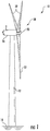
- FIG. 1 illustrates a side view of one embodiment of a wind turbine 10.
- the wind turbine 10 generally includes a tower 12 extending from a support surface 14 (e.g., the ground, a concrete pad or any other suitable support surface).
- the wind turbine 10 may also include a nacelle 16 mounted on the tower 12 and a rotor 18 coupled to the nacelle 16.
- the rotor 18 includes a rotatable hub 20 and at least one rotor blade 22 coupled to and extending outwardly from the hub 20.
- the rotor 18 includes three rotor blades 22.
- the rotor 18 may include more or less than three rotor blades 22.
- Each rotor blade 22 may be spaced about the hub 20 to facilitate rotating the rotor 18 to enable kinetic energy to be transferred from the wind into usable mechanical energy, and subsequently, electrical energy.
- the hub 20 may be rotatably coupled to an electric generator (not shown) positioned within the nacelle 16 to permit electrical energy to be produced.
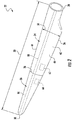
- FIGS. 2 and 3 one embodiment of a segmented rotor blade 22 suitable for use with the wind turbine 10 shown in FIG. 1 is illustrated in accordance with aspects of the present subject matter. Specifically, FIG. 2 illustrates a perspective, assembled view of the rotor blade 22 and FIG. 3 illustrates a perspective, exploded view of the rotor blade 22.
- the rotor blade 22 may generally be formed from a plurality of spanwise blade segments 24, 26 configured to be coupled end-to-end such that the rotor blade 22 extends between a blade root or root end 28 configured to be mounted or otherwise secured to the hub 20 ( FIG. 1 ) of the wind turbine 10 and a blade tip or tip end 30 disposed opposite the blade root 28.
- the rotor blade assembly 22 is formed from two blade segments 24, 26, namely a first blade segment 24 (e.g., a root segment) and a second blade segment 26 (e.g., a tip segment).
- the root segment 24 may generally extend lengthwise between the root end 28 and a first joint end 32.
- the tip segment 26 may generally extend lengthwise between the tip end 30 and a second joint end 34.
- the blade segments 24, 26 may generally be configured to be coupled to one another at their joint ends 32, 34.
- a blade joint 36 may be defined at the joint interface between the root and tip segments 24, 26.
- the rotor blade 22 may be formed from any other suitable number of spanwise blade segments.
- the rotor blade 22 may be formed from three blade segments or more than three blade segments, such as four blade segments, five blade segments, or more than five blade segments.
- each blade segment 24, 26 may include an outer shell 38, 40 configured to extend between the opposed ends of such segment that generally serves as the outer casing/covering of the blade segment 24, 26.
- the root segment 24 may include a first outer shell 38 ( FIG. 3 ) extending lengthwise between the root end 28 and the first joint end 32.
- the tip segment 26 may include a second outer shell 40 ( FIG. 3 ) extending lengthwise between the second joint end 34 and the tip end 30.
- Each of the outer shells 38, 40 may generally be configured to define spanwise sections of the aerodynamic profile of the rotor blade 22.
- the outer shells 38, 40 may collectively define a pressure side 42 and a suction side 44 of the rotor blade 22, with the pressure and suction sides 42, 44 extending between leading and trailing edges 46, 48 of the rotor blade 22.
- the rotor blade 22 when assembled, may also have a span 50 defining the total length between its root and tip ends 28, 30, with the span 50 generally corresponding to the summation of the combined spanwise lengths of the blade segments 24, 26.
- the root segment 24 may define a first spanwise length 52 ( FIG. 3 ) and the tip segment 26 may define a second spanwise length 54 ( FIG. 3 ).
- the rotor blade 22 may define a chord 56 ( FIG. 2 ) corresponding to the total length of the blade between its leading and trailing edges 46, 48.
- the chord 56 may generally vary in length with respect to the span 50 as the rotor blade 22 extends from the its root end 28 to its tip end 30.
- each outer shell 38, 40 of the blade segments 24, 26 may be formed from one or more shell components.
- each outer shell 38, 40 may be formed form a pressure side shell (not shown) forming a portion of the pressure side 42 of the rotor blade 22 and a suction side shell (not shown) forming a portion of the suction side 44 of the rotor blade 22.
- the outer shells 38, 40 may generally be formed from any suitable material.
- each outer shell 38, 40 may be formed from a fiber-reinforced composite, such as a fiber reinforced laminate including a plurality of fibers (e.g., glass or carbon fibers) surrounded by a suitable matrix material (e.g., a thermoset resin material or a thermoplastic resin material).
- a suitable matrix material e.g., a thermoset resin material or a thermoplastic resin material.
- one or more portions of each outer shell 38, 40 may be configured as a layered construction and may include a core material, formed from a lightweight material such as wood (e.g., balsa), foam (e.g., extruded polystyrene foam) or a combination of such materials, disposed between layers of laminate composite material.
- each blade segment 24, 26 may also include one or more internal structural components contained within its outer shell 38, 40 that is configured to provide increased stiffness, buckling resistance and/or strength to the rotor blade 22.
- the root segment 24 may include one or more internal structural components 58 extending within the first outer shell 38, such as by including one or more longitudinally extending structural components (e.g., a pair of opposed spar caps having a shear web extending therebetween) positioned within the first outer shell 38.
- the tip segment 26 may include one or more internal structural components 60 extending within the second outer shell 40, such as by including one or more longitudinally extending structural components (e.g., a pair of opposed spar caps having a shear web extending therebetween) positioned within the second outer shell 40.
- each blade segment 24, 26 may include one or more balance boxes 62, 64 installed within its interior.
- the root segment 24 may include a root balance box 62 while the tip segment 26 may include a tip balance box 64.
- Each balance box 62, 64 may generally correspond to an internal storage compartment or enclosed volume within each blade segment 24, 26 that provides a location for adding mass to the blade segment 24, 26. For instance, as will be described below, mass (e.g., a mixture of sand and resin) may be added to the balance box installed within root segment 24 and/or the tip segment 26 to adjust the static moment associated with the corresponding blade segment(s) 24, 26.
- mass e.g., a mixture of sand and resin
- each balance box 62, 64 may be installed within its corresponding blade segment 24, 26 at any suitable location along the segment's spanwise length 52, 54.
- each balance box 62, 64 may be positioned closer to the joint end 32, 34 of its corresponding blade segment 24, 26 than the opposed end of the blade segment 24, 26.
- each balance box 62, 64 may be located a distance 66 ( FIG.
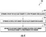
- FIG. 4 a flow diagram of one embodiment of a method 100 for balancing segmented rotor blades of a wind turbine is illustrated in accordance with aspects of the present subject matter.
- the method 100 will be described herein with reference to balancing the blade segments used to form two-piece rotor blades, such as the rotor blade 22 described above with reference to FIGS. 2 and 3 .
- the method 100 may be used to provide balanced rotor blades formed from any other suitable number of blade segments, such as three or more blade segments.
- the disclosed method 100 may be applied to balance a complete set of segmented rotor blades for use with a wind turbine.
- the complete set of segmented rotor blades 22 may include a set of three root segments 24 and a set of three tip segments 26.
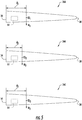
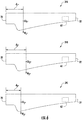
- the method 100 shown in FIG. 4 will be described particularly with reference to FIG. 5 , which illustrates a set of three tip segments 26, namely a first tip segment 26A, a second tip segment 26B, and a third segment 26C.
- the method 100 described herein may be similarly applied to a set of a root segments 24.
- the method 100 may include determining a weight for each blade segment of a given type/model being balanced (e.g., each tip segment 26 of a given configuration or each root segment 24 of a given configuration).
- the weight for each blade segment may be determined using any suitable means and/or methodology for weighing or otherwise calculating the weight of blade segments. For instance, in one embodiment, a scale or any other suitable weighing device may be used to determine the weight of each blade segment.
- the weight for each blade segment may be determined mathematically, such as by calculating the weight based on the dimensions of each blade segment and the properties of the material(s) used to form each blade segment.
- each of the tip segments 26A, 26B, 26C may be weighed or otherwise analyzed to determine its weight.
- the first tip segment 26A may have a first weight (Wi)
- the second tip segment 26B may have a second weight (W 2 )
- the third tip segment 26C may have a third weight (W 3 ).
- the weight of at least one of the tip segments 26A, 26B, 26C may differ from the weights of the remainder of the tip segments.
- each tip segment 26A, 26B, 26C may have a weight that differs from the weight of the other tip segments 26A, 26B, 26C at least slightly due to manufacturing tolerances and/or other limitations.
- each tip segment 26A, 26B, 26C may be represented by a center of gravity.
- the first tip segment 26A may define a first center of gravity (CGi)
- the second tip segment 26B may define a second center of gravity (CG 2 )
- the third tip segment 26C may define a third center of gravity (CG 3 ).
- the location of the center of gravity of at least one of the tip segments 26A, 26B, 26C may differ from the locations of the centers of gravity of the remainder of the tip segments.
- each tip segment 26A, 26B, 26C may have a center of gravity that is defined at a different location than the centers of gravity of the other tip segments due to manufacturing tolerances and/or other limitations.
- the method 100 may include determining an initial static moment for each blade segment being balanced.
- the static moment for a given blade segment may be determined as a function of its weight and the location of its center of gravity relative to a fixed reference point.
- the static moment for each tip segment 26A, 26B, 26C may be calculated based on the determined weight of each tip segment 26A, 26B, 26C and the distance defines between each tip segment's center of gravity and a fixed reference point (e.g., the joint end 34 of each tip segment 26A, 26B, 26C).
- the first tip segment 26A may define a first distance (d 1 ) between its joint end 34 and center of gravity (CG 1 )
- the second tip segment 26B may define a second distance (d 2 ) between its joint end 34 and center of gravity (CG 2 )
- the third tip segment 26C may define a third distance (d 3 ) between its joint end 34 and center of gravity (CG 3 ).
- the initial static moment of the first tip segment 26A may be calculated by multiplying its weight (W 1 ) by the first distance (d 1 ).
- the initial static moment of the second tip segment 26B may be calculated by multiplying its weight (W 2 ) by the second distance (d 2 ) while the initial static moment of the third tip segment 26C may be calculated by multiplying its weight (W 3 ) by the third distance (d 3 ).
- the initial static moment of at least one of the tip segments 26A, 26B, 26C may differ from the initial static moments of the remainder of the tip segments.
- each tip segment 26A, 26B, 26C may have an initial static moment that differs from the initial static moments of the other tip segments at least slightly due to manufacturing tolerances and/or other limitations.
- the method 100 may include adding mass to each of the plurality of blade segments to increase the initial static moment for each blade segment to a predetermined static moment.
- each blade segment may include a balance box 62, 64 within which mass may be added to adjust the static moment of the blade segment.
- mass may be added to adjust the static moment of the blade segment.
- a mixture of resin and sand may be used to create a thick slurry of material to be added within the balance box 62, 64 of each blade segment.
- any other suitable material(s) may be placed within the balance box 62, 64 of each blade segment to increase its mass and, thus, its corresponding static moment.
- mass may be added to each of the blade segments without requiring the use of a balance box.
- additional material(s) e.g., resins, adhesives, weights, etc.
- the predetermined static moment may correspond to a static moment that is greater than the initial static moment of each of the blade segments being balanced of a given type/model (e.g., a predetermined tip static moment that is greater than the initial static moment of each of the tip segments 26 being balanced and/or a predetermined root static moment that is greater than the initial static moment of each of the root segments 24 being balanced).
- each blade segment being balanced may require that mass be added to its balance box (or at any other suitable location(s)) to allow the initial static moment of the blade segment to be increased to the predetermined static moment.
- the predetermined static moment may be selected so as to correspond to a static moment that is greater than a maximum static moment allowed for a blade segment of a given type/model based on manufacturing tolerances and/or other limitations. For instance, based on allowable manufacturing variations, it may be determined that all or statistically all (e.g., 99.9%) of a given type/model of blade segment (e.g., a tip segment 26 or root segment 24) will have an initial static moment that is less than a given maximum static moment.
- a given type/model of blade segment e.g., a tip segment 26 or root segment 24
- the predetermined static moment may be set as the maximum static moment for such type/model of blade segment or the predetermined static moment may be set as a static moment that is greater than the maximum static moment (e.g., 1%-5% greater than the maximum static moment).
- the blade segments may be interchangeable with one another when assembling such blade segments with other blade segments to form a complete segmented rotor blade.
- the blade segments may be used to a form a balanced rotor set without the need for re-weighing or re-balancing the segments in the field and/or without requiring the blade segments to be specifically matched with other corresponding blade segments.
- mass may be added to the balance box 64 of each of the tip segments 26A, 26B, 26C to increase the initial static moment of each tip segment to a predetermined tip static moment.
- the initial static moments of the tip segments 26A, 26B, 26C may vary from segment-to-segment.
- a different amount of mass may need to be added to each tip segment 26A, 26B, 26C to increase its static moment to the predetermined tip static moment.
- FIG. 6 illustrates a set of three root segments, namely a first root segment 24A, a second root segment 24B, and a third root segment 24C.
- the first root segment 24A has a first weight (W 1* ) and defines a first distance (d 1* ) between its root end 28 and center of gravity (CG 1* ).
- the second root segment 24B has a second weight (W 2* ) and defines a second distance (d 2* ) between its root end 28 and center of gravity (CG 2* ).
- the third root segment 24C has a third weight (W 3* ) and defines a third distance (d 3* ) between its root end 28 and center of gravity (CG 3* ).
- the method 100 may be applied by determining both the weight of each root segment 24A, 24B, 24C and its corresponding initial static moment (e.g., as a function of the weight and the distance defined between the center of gravity and the segment's root end 28). Thereafter, mass may be added to each of the root segments 24A, 24B, 24C to increase the initial static moment of each root segment to a predetermined root static moment that is greater than the largest initial static moment of the root segments 24A, 24B, 24C.
- root segments are typically provided with larger allowable manufacturing variance ranges than tip segments, it may be desirable, in alternative embodiments, to set the predetermined root static moment based on the maximum initial static moment of the specific set of root segments being balanced as opposed to a static moment that exceeds the initial static moments of each of the root segments. For instance, when balancing the set of three root segments 24A, 24B, 24C shown in FIG. 6 , the weight and initial static moment of each root segment 24A, 24B, 24C may be determined. Thereafter, the root segment having the largest initial static moment may be identified, with its initial static moment being set as the predetermined root static moment for the remainder of the root segments. Mass may then be added to the other root segments to increase their initial static moments to the predetermined root static moment such that each root segment has the same static moment.
- each root segment 24A, 24B, 24C may be simply paired to a corresponding balanced tip segment (e.g., tip segments 26A, 26B, 26C) without the need to match the root segments to specific tip segments in attempt to create a balanced set of rotor blades for a given wind turbine.
- a corresponding balanced tip segment e.g., tip segments 26A, 26B, 26C
Description
- The present subject matter relates generally to segmented rotor blades for wind turbines and, more particularly, to a method for balancing segmented rotor blades for use within a wind turbine.
- Wind power is considered one of the cleanest, most environmentally friendly energy sources presently available, and wind turbines have gained increased attention in this regard. A modern wind turbine typically includes a tower, a generator, a gearbox, a nacelle, and a rotor having a rotatable hub with three rotor blades extending outwardly from the hub. The rotor blades capture kinetic energy of wind using known airfoil principles. The rotor blades transmit the kinetic energy in the form of rotational energy so as to turn a shaft coupling the rotor blades to a gearbox, or if a gearbox is not used, directly to the generator. The generator then converts the mechanical energy to electrical energy that may be deployed to a utility grid.
- When installing rotor blades on a wind turbine, careful attention must be placed to balancing out the rotor blades to ensure that a balanced load is applied to the rotor during operation of the wind turbine. Typically, blade balancing occurs in the field, with each full rotor blade being weighed and balanced relative to the other rotor blades. Unfortunately, the current field-implemented blade balancing process has many disadvantages, including being quite time consuming and cumbersome. In addition, with segmented rotor blades becoming more popular, the disadvantages of the conventional blade balancing process have been exacerbated by the need to balance multiple components for each rotor blade in order to form a fully balanced rotor set. See, for example,
EP 3 034 861EP 3 025 053 - Accordingly, an improved method for balancing segmented rotor blades of a wind turbine would be welcomed in the technology.
- Various aspects and advantages of the invention will be set forth in part in the following description, or may be clear from the description, or may be learned through practice of the invention.
- The present invention is defined by the appended claims.
- Various features, aspects and advantages of the present invention will become better understood with reference to the following description and appended claims. The accompanying drawings, which are incorporated in and constitute a part of this specification, illustrate embodiments of the invention and, together with the description, serve to explain the principles of the invention.
- In the drawings:
-
FIG. 1 illustrates a side view of one embodiment of a wind turbine in accordance with aspects of the present subject matter; -
FIG. 2 illustrates a perspective view of one embodiment of a segmented rotor blade suitable for use with the wind turbine shown inFIG. 1 in accordance with aspects of the present subject matter; -
FIG. 3 illustrates an exploded view of the segmented rotor blade shown inFIG. 2 , particularly illustrating a root segment of the rotor blade exploded away from a tip segment of the rotor blade; -
FIG. 4 illustrates a flow diagram of one embodiment of a method for balancing segmented rotor blades of a wind turbine in accordance with aspects of the present subject matter; -
FIG. 5 illustrates a simplified view of a set of tip segments suitable for use within segmented rotor blades, particularly identifying various parameters that may be used to determine the static moment of each tip segment; and -
FIG. 6 illustrates a simplified view of a set of root segments suitable for use within segmented rotor blades, particularly identifying various parameters that may be used to determine the static moment of each root segment. - Reference now will be made in detail to embodiments of the invention, one or more examples of which are illustrated in the drawings. Each example is provided by way of explanation of the invention, not limitation of the invention. In fact, it will be apparent to those skilled in the art that various modifications and variations can be made in the present invention without departing from the scope or spirit of the invention. For instance, features illustrated or described as part of one embodiment can be used with another embodiment to yield a still further embodiment. Thus, it is intended that the present invention covers such modifications and variations as come within the scope of the appended claims and their equivalents.
- In general, the present subject matter is directed to methods for balancing segmented rotor blades of a wind turbine. Specifically, in several embodiments, the disclosed method provides for sets of blade segments of a given type/model (e.g., tip segments or root segments) to be balanced relative to one another independent of the full rotor blade assembly, which may allow for the blade segments to be balanced in a manufacturing setting (e.g., in a controlled, factory environment) as opposed to in the field. Once balanced, the blade segments may be joined with their corresponding blade segments in the field without requiring the various blade segments to be re-weighed and/or re-balanced. For instance, in one embodiment, a set of tip segments may be balanced relative to one another such that each tip segment defines the same tip static moment while a corresponding set of root segments may be balanced relative to one another such that each root segment defines the same root static moment prior to such blade segments being shipped to the field. Once at the field, the tip and root sections may be joined together without requiring any further weighing or balancing to form a fully balanced rotor set.
- Referring now to the drawings,
FIG. 1 illustrates a side view of one embodiment of awind turbine 10. As shown, thewind turbine 10 generally includes atower 12 extending from a support surface 14 (e.g., the ground, a concrete pad or any other suitable support surface). In addition, thewind turbine 10 may also include anacelle 16 mounted on thetower 12 and arotor 18 coupled to thenacelle 16. Therotor 18 includes arotatable hub 20 and at least onerotor blade 22 coupled to and extending outwardly from thehub 20. For example, in the illustrated embodiment, therotor 18 includes threerotor blades 22. However, in an alternative embodiment, therotor 18 may include more or less than threerotor blades 22. Eachrotor blade 22 may be spaced about thehub 20 to facilitate rotating therotor 18 to enable kinetic energy to be transferred from the wind into usable mechanical energy, and subsequently, electrical energy. For instance, thehub 20 may be rotatably coupled to an electric generator (not shown) positioned within thenacelle 16 to permit electrical energy to be produced. - Referring now to
FIGS. 2 and3 , one embodiment of a segmentedrotor blade 22 suitable for use with thewind turbine 10 shown inFIG. 1 is illustrated in accordance with aspects of the present subject matter. Specifically,FIG. 2 illustrates a perspective, assembled view of therotor blade 22 andFIG. 3 illustrates a perspective, exploded view of therotor blade 22. - As shown, the
rotor blade 22 may generally be formed from a plurality ofspanwise blade segments rotor blade 22 extends between a blade root orroot end 28 configured to be mounted or otherwise secured to the hub 20 (FIG. 1 ) of thewind turbine 10 and a blade tip ortip end 30 disposed opposite theblade root 28. For example, in the illustrated embodiment, therotor blade assembly 22 is formed from twoblade segments FIG. 3 , theroot segment 24 may generally extend lengthwise between theroot end 28 and a firstjoint end 32. Similarly, thetip segment 26 may generally extend lengthwise between thetip end 30 and a secondjoint end 34. In such an embodiment, theblade segments joint ends FIG. 2 , when theblade segments joint ends blade joint 36 may be defined at the joint interface between the root andtip segments - It should be appreciated that, in other embodiments, the
rotor blade 22 may be formed from any other suitable number of spanwise blade segments. For instance, therotor blade 22 may be formed from three blade segments or more than three blade segments, such as four blade segments, five blade segments, or more than five blade segments. - In general, each
blade segment outer shell blade segment root segment 24 may include a first outer shell 38 (FIG. 3 ) extending lengthwise between theroot end 28 and the firstjoint end 32. Similarly, thetip segment 26 may include a second outer shell 40 (FIG. 3 ) extending lengthwise between the secondjoint end 34 and thetip end 30. Each of theouter shells rotor blade 22. As such, theouter shells pressure side 42 and asuction side 44 of therotor blade 22, with the pressure andsuction sides trailing edges rotor blade 22. - As shown in
FIG. 2 , when assembled, therotor blade 22 may also have aspan 50 defining the total length between its root andtip ends span 50 generally corresponding to the summation of the combined spanwise lengths of theblade segments root segment 24 may define a first spanwise length 52 (FIG. 3 ) and thetip segment 26 may define a second spanwise length 54 (FIG. 3 ). In addition, therotor blade 22 may define a chord 56 (FIG. 2 ) corresponding to the total length of the blade between its leading andtrailing edges chord 56 may generally vary in length with respect to thespan 50 as therotor blade 22 extends from the itsroot end 28 to itstip end 30. - It should be appreciated that, in several embodiments, the
outer shells blade segments outer shell pressure side 42 of therotor blade 22 and a suction side shell (not shown) forming a portion of thesuction side 44 of therotor blade 22. In addition, theouter shells outer shell outer shell - Additionally, in several embodiments, each
blade segment outer shell rotor blade 22. For example, as shown inFIGS. 2 and3 , theroot segment 24 may include one or more internalstructural components 58 extending within the firstouter shell 38, such as by including one or more longitudinally extending structural components (e.g., a pair of opposed spar caps having a shear web extending therebetween) positioned within the firstouter shell 38. Similarly, as shown inFIGS. 2 and3 , thetip segment 26 may include one or more internalstructural components 60 extending within the secondouter shell 40, such as by including one or more longitudinally extending structural components (e.g., a pair of opposed spar caps having a shear web extending therebetween) positioned within the secondouter shell 40. - Additionally, in accordance with aspects of the present subject matter, each
blade segment more balance boxes root segment 24 may include aroot balance box 62 while thetip segment 26 may include atip balance box 64. Eachbalance box blade segment blade segment root segment 24 and/or thetip segment 26 to adjust the static moment associated with the corresponding blade segment(s) 24, 26. - It should be appreciated that, in general, each
balance box blade segment spanwise length balance box joint end corresponding blade segment blade segment balance box FIG. 3 ) (e.g., as measured from the center of eachbox 62, 64) away from thejoint end corresponding blade segment spanwise length corresponding blade segment 24, 25, such as less than 20% of the totalspanwise length spanwise length spanwise length - Referring now to
FIG. 4 , a flow diagram of one embodiment of amethod 100 for balancing segmented rotor blades of a wind turbine is illustrated in accordance with aspects of the present subject matter. In general, themethod 100 will be described herein with reference to balancing the blade segments used to form two-piece rotor blades, such as therotor blade 22 described above with reference toFIGS. 2 and3 . However, in other embodiments, themethod 100 may be used to provide balanced rotor blades formed from any other suitable number of blade segments, such as three or more blade segments. - It should also be appreciated that the disclosed
method 100 may be applied to balance a complete set of segmented rotor blades for use with a wind turbine. Thus, for example, with reference to the embodiment described above with reference toFIGS. 2 and3 , the complete set ofsegmented rotor blades 22 may include a set of threeroot segments 24 and a set of threetip segments 26. To illustrate balancing theblade segments rotor blades 22, themethod 100 shown inFIG. 4 will be described particularly with reference toFIG. 5 , which illustrates a set of threetip segments 26, namely afirst tip segment 26A, asecond tip segment 26B, and athird segment 26C. However, it should be appreciated that themethod 100 described herein may be similarly applied to a set of aroot segments 24. - As shown in
FIG. 4 , at (102), themethod 100 may include determining a weight for each blade segment of a given type/model being balanced (e.g., eachtip segment 26 of a given configuration or eachroot segment 24 of a given configuration). In general, the weight for each blade segment may be determined using any suitable means and/or methodology for weighing or otherwise calculating the weight of blade segments. For instance, in one embodiment, a scale or any other suitable weighing device may be used to determine the weight of each blade segment. Alternatively, the weight for each blade segment may be determined mathematically, such as by calculating the weight based on the dimensions of each blade segment and the properties of the material(s) used to form each blade segment. - As particularly shown in the embodiment of
FIG. 5 , each of thetip segments first tip segment 26A may have a first weight (Wi), thesecond tip segment 26B may have a second weight (W2), and thethird tip segment 26C may have a third weight (W3). In one embodiment, the weight of at least one of thetip segments tip segment other tip segments - As is generally understood, the average location of the weight of each
tip segment FIG. 5 , thefirst tip segment 26A may define a first center of gravity (CGi), thesecond tip segment 26B may define a second center of gravity (CG2), and thethird tip segment 26C may define a third center of gravity (CG3). In one embodiment, the location of the center of gravity of at least one of thetip segments tip segment - Referring back to
FIG. 4 , at (104), themethod 100 may include determining an initial static moment for each blade segment being balanced. As is generally understood, the static moment for a given blade segment may be determined as a function of its weight and the location of its center of gravity relative to a fixed reference point. For instance, the static moment may be calculated using the following equation (Equation 1):
- For instance, using the example shown in
FIG. 5 , the static moment for eachtip segment tip segment joint end 34 of eachtip segment first tip segment 26A may define a first distance (d1) between itsjoint end 34 and center of gravity (CG1), thesecond tip segment 26B may define a second distance (d2) between itsjoint end 34 and center of gravity (CG2), and thethird tip segment 26C may define a third distance (d3) between itsjoint end 34 and center of gravity (CG3). Thus, the initial static moment of thefirst tip segment 26A may be calculated by multiplying its weight (W1) by the first distance (d1). Similarly, the initial static moment of thesecond tip segment 26B may be calculated by multiplying its weight (W2) by the second distance (d2) while the initial static moment of thethird tip segment 26C may be calculated by multiplying its weight (W3) by the third distance (d3). In one embodiment, the initial static moment of at least one of thetip segments tip segment - Referring again back to
FIG. 4 , at (106), themethod 100 may include adding mass to each of the plurality of blade segments to increase the initial static moment for each blade segment to a predetermined static moment. Specifically, as indicated above, each blade segment may include abalance box balance box balance box - It should be appreciated that, in other embodiments, mass may be added to each of the blade segments without requiring the use of a balance box. For instance, in one embodiment, additional material(s) (e.g., resins, adhesives, weights, etc.) may simply be positioned within the interior of each blade segment at any suitable location to increase its mass, such as by coupling the additional material(s) to an interior surface or wall of the blade segment.
- Additionally, it should be appreciated that, in the several embodiments, the predetermined static moment may correspond to a static moment that is greater than the initial static moment of each of the blade segments being balanced of a given type/model (e.g., a predetermined tip static moment that is greater than the initial static moment of each of the
tip segments 26 being balanced and/or a predetermined root static moment that is greater than the initial static moment of each of theroot segments 24 being balanced). As such, each blade segment being balanced may require that mass be added to its balance box (or at any other suitable location(s)) to allow the initial static moment of the blade segment to be increased to the predetermined static moment. In one embodiment, the predetermined static moment may be selected so as to correspond to a static moment that is greater than a maximum static moment allowed for a blade segment of a given type/model based on manufacturing tolerances and/or other limitations. For instance, based on allowable manufacturing variations, it may be determined that all or statistically all (e.g., 99.9%) of a given type/model of blade segment (e.g., atip segment 26 or root segment 24) will have an initial static moment that is less than a given maximum static moment. In such instance, the predetermined static moment may be set as the maximum static moment for such type/model of blade segment or the predetermined static moment may be set as a static moment that is greater than the maximum static moment (e.g., 1%-5% greater than the maximum static moment). - By increasing the static moment of each of the blade segments being balanced to a common or predetermined static moment, the blade segments may be interchangeable with one another when assembling such blade segments with other blade segments to form a complete segmented rotor blade. A such, the blade segments may be used to a form a balanced rotor set without the need for re-weighing or re-balancing the segments in the field and/or without requiring the blade segments to be specifically matched with other corresponding blade segments.
- For instance, in the embodiment shown in
FIG. 5 , mass may be added to thebalance box 64 of each of thetip segments tip segments tip segment tip segment - As indicated above, it should be appreciated that the
method 100 described with reference toFIG. 4 may be similarly applied toroot segments 24. For instance,FIG. 6 illustrates a set of three root segments, namely afirst root segment 24A, asecond root segment 24B, and athird root segment 24C. As shown, thefirst root segment 24A has a first weight (W1*) and defines a first distance (d1*) between itsroot end 28 and center of gravity (CG1*). Similarly, thesecond root segment 24B has a second weight (W2*) and defines a second distance (d2*) between itsroot end 28 and center of gravity (CG2*). Additionally, thethird root segment 24C has a third weight (W3*) and defines a third distance (d3*) between itsroot end 28 and center of gravity (CG3*). In such an embodiment, themethod 100 may be applied by determining both the weight of eachroot segment root segments root segments - Given that root segments are typically provided with larger allowable manufacturing variance ranges than tip segments, it may be desirable, in alternative embodiments, to set the predetermined root static moment based on the maximum initial static moment of the specific set of root segments being balanced as opposed to a static moment that exceeds the initial static moments of each of the root segments. For instance, when balancing the set of three
root segments FIG. 6 , the weight and initial static moment of eachroot segment - By balancing sets of three
root segments root segment tip segments - This written description uses examples to disclose the invention, including the preferred mode, and also to enable any person skilled in the art to practice the invention, including making and using any devices or systems and performing any incorporated methods. The patentable scope of the invention is defined by the claims, and may include other examples that occur to those skilled in the art. Such other examples are intended to be within the scope of the claims if they include structural elements that do not differ from the literal language of the claims, or if they include equivalent structural elements with insubstantial differences from the literal languages of the claims.
Claims (8)
- A method (100) for balancing segmented rotor blades (22) for a wind turbine (10), the method (100) comprising:determining a weight for each of a plurality of blade segments (26), each blade segment (26) extending between a first end (34) and a second end (30) and being configured to form a common spanwise section of a segmented rotor blade (22) between the first (34) and second ends (30);determining an initial static moment for each blade segment (26) based on the weight of the blade segment (26), the initial static moment of at least one of the blade segments (26) differing from the initial static moments of the remainder of the plurality of blade segments (26); andadding mass to each of the plurality of blade segments (26) to increase the initial static moment for each blade segment (26) to a predetermined static moment, the predetermined static moment being greater than each of the initial static moments of the plurality of blade segments (26);wherein the predetermined static moment corresponds to a static moment that is equal to or greater than a maximum static moment for the plurality of blade segments (26) based on allowable manufacturing variations.
- The method (100) of claim 1, wherein each blade segment (26) corresponds to a tip segment (26), the first end (34) corresponding to a joint end (34) of the tip segment (26) and the second end (30) corresponding to a tip end (30) of the tip segment (26), the joint end (34) being configured to be coupled to a corresponding root segment (24) of the segmented rotor blade (22).
- The method (100) of any preceding claim, wherein each blade segment (26) corresponds to a root segment (24), the first end (34) corresponding to a root end (28) of the root segment (24) and the second end (30) corresponding to a joint end (32) of the root segment (24), the joint end (32) being configured to be coupled to a corresponding tip segment (26) of the segmented rotor blade (22).
- The method (100) of any preceding claim, further comprising determining a center of gravity for each blade segment (26).
- The method (100) of claim 4, wherein determining the initial static moment for each blade segment (26) comprises determining the initial static moment based on the weight and the center of gravity for each blade segment (26).
- The method (100) of any preceding claim, wherein adding mass to each of the plurality of blade segments (26) comprises adding mass within a balance box (64) installed within an interior of each of the plurality of blade segments (26).
- The method (100) of any preceding claim, wherein the first end (34) of each of the plurality of blade segments (26) corresponds to a joint end (34) of each blade segment (26) and each blade segment (26) defines a spanwise length (54) between the first (34) and second ends (30), the balance box (64) being located within the interior of each blade segment (26) a distance (66) from the joint end (34) equal to less than 25% of the spanwise length (54).
- The method (100) of any preceding claim, wherein the initial static moment of each blade segment (26) differs from the initial static moments of the remainder of the plurality of blade segments (26).
Applications Claiming Priority (1)
| Application Number | Priority Date | Filing Date | Title |
|---|---|---|---|
| US15/232,900 US10550823B2 (en) | 2016-08-10 | 2016-08-10 | Method for balancing segmented wind turbine rotor blades |
Publications (2)
| Publication Number | Publication Date |
|---|---|
| EP3282121A1 EP3282121A1 (en) | 2018-02-14 |
| EP3282121B1 true EP3282121B1 (en) | 2019-02-27 |
Family
ID=59523029
Family Applications (1)
| Application Number | Title | Priority Date | Filing Date |
|---|---|---|---|
| EP17184806.2A Active EP3282121B1 (en) | 2016-08-10 | 2017-08-03 | Method for balancing segmented wind turbine rotor blades |
Country Status (3)
| Country | Link |
|---|---|
| US (1) | US10550823B2 (en) |
| EP (1) | EP3282121B1 (en) |
| CN (1) | CN107725268B (en) |
Families Citing this family (4)
| Publication number | Priority date | Publication date | Assignee | Title |
|---|---|---|---|---|
| US10550823B2 (en) * | 2016-08-10 | 2020-02-04 | General Electric Company | Method for balancing segmented wind turbine rotor blades |
| US11548627B2 (en) * | 2016-08-15 | 2023-01-10 | Sikorsky Aircraft Corporation | Core matertal for balanced rotor blade |
| CN112714827B (en) * | 2018-07-20 | 2023-07-21 | 维斯塔斯风力系统有限公司 | Method for balancing turbine blades and blade assembly |
| CN116075635A (en) * | 2020-09-09 | 2023-05-05 | 维斯塔斯风力系统有限公司 | Wind turbine blade |
Citations (6)
| Publication number | Priority date | Publication date | Assignee | Title |
|---|---|---|---|---|
| US20100170339A1 (en) | 2009-01-05 | 2010-07-08 | Michael Alfred Wilhelm Lenz | Method for balancing radical projections detached from a rotating assembly |
| EP2455611A2 (en) | 2010-11-18 | 2012-05-23 | Envision Energy (Denmark) ApS | Pitch system balancing for a wind turbine |
| WO2015011292A1 (en) | 2013-07-26 | 2015-01-29 | Societe Europeenne D'ingenierie Et De Developpement Des Energies Renouvelables | Segmented wind turbine blade and wind turbine provided with such a blade |
| US20150082634A1 (en) | 2013-09-23 | 2015-03-26 | Sikorsky Aircraft Corporation | Method and apparatus for rotor blade balance |
| US20150110632A1 (en) | 2012-05-30 | 2015-04-23 | youWINenergy GmbH | Blade assembly for a wind turbine rotor |
| EP3034861A1 (en) | 2014-12-18 | 2016-06-22 | Acciona Windpower S.a. | Balancing method of wind turbine rotors |
Family Cites Families (46)
| Publication number | Priority date | Publication date | Assignee | Title |
|---|---|---|---|---|
| DE2528007C2 (en) * | 1975-06-24 | 1984-04-19 | Messerschmitt-Bölkow-Blohm GmbH, 8000 München | Procedure for correcting the center of gravity and the weight of rotor blades |
| GB8529782D0 (en) | 1985-12-03 | 1986-01-08 | Orchard O J | Paying off fine material & fibres under constant tension |
| DE19962989B4 (en) * | 1999-12-24 | 2006-04-13 | Wobben, Aloys, Dipl.-Ing. | Rotor blade for wind turbines |
| US6726439B2 (en) | 2001-08-22 | 2004-04-27 | Clipper Windpower Technology, Inc. | Retractable rotor blades for power generating wind and ocean current turbines and means for operating below set rotor torque limits |
| US6976829B2 (en) | 2003-07-16 | 2005-12-20 | Sikorsky Aircraft Corporation | Rotor blade tip section |
| JP2007198265A (en) * | 2006-01-26 | 2007-08-09 | Kawasaki Heavy Ind Ltd | Arranging method of turbine blade |
| US7654799B2 (en) | 2006-04-30 | 2010-02-02 | General Electric Company | Modular rotor blade for a wind turbine and method for assembling same |
| KR20090033905A (en) | 2006-07-21 | 2009-04-06 | 클립퍼 윈드파워 테크놀로지 인코포레이티드 | Retractable rotor blade structure |
| MX2010007668A (en) | 2008-01-14 | 2010-09-30 | Clipper Windpower Inc | A modular rotor blade for a power-generating turbine and a method for assembling a power-generating turbine with modular rotor blades. |
| EP2288807B1 (en) * | 2008-05-07 | 2013-09-18 | Vestas Wind Systems A/S | A sectional blade |
| DE102008045601A1 (en) * | 2008-06-27 | 2009-12-31 | Repower Systems Ag | Rotor blade for a wind energy plant and method and production form for its production |
| US8497601B2 (en) * | 2008-09-27 | 2013-07-30 | Witricity Corporation | Wireless energy transfer converters |
| CA2650720A1 (en) * | 2009-01-22 | 2010-07-22 | Sharolyn Vettese | Rotating system balancing assembly |
| DK2233904T3 (en) * | 2009-03-25 | 2012-07-16 | Siemens Ag | Device for determining a static torque of a blade |
| CN201420645Y (en) * | 2009-06-03 | 2010-03-10 | 中船重工(重庆)海装风电设备有限公司 | Sectionalized vane of wind driven generator |
| EP2317124B1 (en) | 2009-10-01 | 2018-08-08 | Vestas Wind Systems A/S | Wind turbine blade |
| CN201593478U (en) * | 2009-12-28 | 2010-09-29 | 浙江恒通机械有限公司 | Blade of butt joint type wind turbine |
| US8398374B2 (en) * | 2010-01-27 | 2013-03-19 | General Electric Company | Method and apparatus for a segmented turbine bucket assembly |
| WO2011149990A2 (en) * | 2010-05-24 | 2011-12-01 | Arendt Cory P | Segmented wind turbine blades with truss connection regions, and associated systems and methods |
| JP4939640B2 (en) * | 2010-10-22 | 2012-05-30 | 三菱重工業株式会社 | Wind turbine rotor |
| DK177278B1 (en) * | 2011-05-19 | 2012-09-17 | Envision Energy Denmark Aps | A wind turbine and associated control method |
| BR112014002704A2 (en) * | 2011-08-05 | 2015-04-22 | Tecsis Tecnologia E Sist S Avançados S A | Windmill blade tip segment and mounting method |
| US20120141287A1 (en) * | 2011-08-29 | 2012-06-07 | General Electric Company | Wind turbine rotor blade joint |
| US8918997B2 (en) * | 2011-10-13 | 2014-12-30 | General Electric Company | Method for assembling a multi-segment wind turbine rotor blade with span-wise offset joints |
| DE102012209935A1 (en) * | 2011-12-08 | 2013-06-13 | Wobben Properties Gmbh | Rear box, rotor blade with rear box and wind turbine with such rotor blade |
| DE102011088025A1 (en) * | 2011-12-08 | 2013-06-13 | Wobben Properties Gmbh | Rotor blade for horizontal axle wind turbine, has anchoring element anchored in blade outer part, counter element anchored in blade inner part, and connecting bolts reaching through counter element and fastened in anchoring element |
| DE102012201470A1 (en) * | 2012-02-01 | 2013-08-01 | Aktiebolaget Skf | Wind turbine |
| IN2012DE00572A (en) * | 2012-02-29 | 2015-06-05 | Gen Electric | |
| FR2989723B1 (en) * | 2012-04-20 | 2024-02-09 | Astrium Sas | ASSEMBLY OF STRUCTURES OF STRUCTURAL PARTS |
| US9394881B2 (en) * | 2013-05-29 | 2016-07-19 | Siemens Aktiengesellschaft | Wind turbine blade and method of fabricating a wind turbine blade |
| US9353729B2 (en) * | 2013-07-02 | 2016-05-31 | General Electric Company | Aerodynamic hub assembly for a wind turbine |
| US9605651B2 (en) * | 2013-12-04 | 2017-03-28 | General Electric Company | Spar assembly for a wind turbine rotor blade |
| DE102014204017A1 (en) * | 2014-03-05 | 2015-09-10 | Robert Bosch Gmbh | Method and device for rotor blade adjustment for a wind turbine |
| US20150369211A1 (en) * | 2014-06-19 | 2015-12-24 | General Electric Company | Wind blade tip joint |
| DK3286430T3 (en) * | 2015-04-23 | 2020-04-06 | Envision Energy Denmark Aps | Method for correcting imbalance in the rotor and wind turbine thereof |
| US10533534B2 (en) * | 2015-09-09 | 2020-01-14 | General Electric Company | Composite layers for bonding components of a wind turbine rotor blade |
| US9951751B2 (en) * | 2015-09-30 | 2018-04-24 | General Electric Company | Segmented wind turbine rotor blade with rod and tube joint connection |
| US20170145986A1 (en) * | 2015-11-25 | 2017-05-25 | General Electric Company | Custom fit blade tip for a rotor blade assembly of a wind turbine and method of fabrication |
| US11187203B2 (en) * | 2015-11-30 | 2021-11-30 | Vestas Wind Systems A/S | Wind turbines, wind turbine blades, and methods for manufacturing wind turbine blades |
| US10760544B2 (en) * | 2016-06-20 | 2020-09-01 | General Electric Company | Sealing members for jointed rotor blade assemblies |
| US10550823B2 (en) * | 2016-08-10 | 2020-02-04 | General Electric Company | Method for balancing segmented wind turbine rotor blades |
| US20180051672A1 (en) * | 2016-08-19 | 2018-02-22 | General Electric Company | Jointed rotor blade for wind turbine |
| US20180118084A1 (en) * | 2016-10-27 | 2018-05-03 | Logisticus Projects Group | Turbine blade disposal system |
| US10723448B2 (en) * | 2016-11-14 | 2020-07-28 | Textron Innovations Inc. | Rotor blade weight system |
| DE102017206349B4 (en) * | 2017-04-12 | 2019-04-11 | Siemens Gamesa Renewable Energy A/S | Weighing device for a wind turbine rotor blade |
| AU2018266819A1 (en) * | 2017-05-10 | 2019-12-05 | Gerald BARBER | Segmented airfoil design for guide wires |
-
2016
- 2016-08-10 US US15/232,900 patent/US10550823B2/en active Active
-
2017
- 2017-08-03 EP EP17184806.2A patent/EP3282121B1/en active Active
- 2017-08-10 CN CN201710680416.6A patent/CN107725268B/en active Active
Patent Citations (6)
| Publication number | Priority date | Publication date | Assignee | Title |
|---|---|---|---|---|
| US20100170339A1 (en) | 2009-01-05 | 2010-07-08 | Michael Alfred Wilhelm Lenz | Method for balancing radical projections detached from a rotating assembly |
| EP2455611A2 (en) | 2010-11-18 | 2012-05-23 | Envision Energy (Denmark) ApS | Pitch system balancing for a wind turbine |
| US20150110632A1 (en) | 2012-05-30 | 2015-04-23 | youWINenergy GmbH | Blade assembly for a wind turbine rotor |
| WO2015011292A1 (en) | 2013-07-26 | 2015-01-29 | Societe Europeenne D'ingenierie Et De Developpement Des Energies Renouvelables | Segmented wind turbine blade and wind turbine provided with such a blade |
| US20150082634A1 (en) | 2013-09-23 | 2015-03-26 | Sikorsky Aircraft Corporation | Method and apparatus for rotor blade balance |
| EP3034861A1 (en) | 2014-12-18 | 2016-06-22 | Acciona Windpower S.a. | Balancing method of wind turbine rotors |
Also Published As
| Publication number | Publication date |
|---|---|
| US20180045174A1 (en) | 2018-02-15 |
| US10550823B2 (en) | 2020-02-04 |
| CN107725268B (en) | 2021-03-16 |
| CN107725268A (en) | 2018-02-23 |
| EP3282121A1 (en) | 2018-02-14 |
Similar Documents
| Publication | Publication Date | Title |
|---|---|---|
| EP3282121B1 (en) | Method for balancing segmented wind turbine rotor blades | |
| US10273935B2 (en) | Rotor blades having structural skin insert and methods of making same | |
| Kong et al. | Structural investigation of composite wind turbine blade considering various load cases and fatigue life | |
| US10760545B2 (en) | Joint configuration for a segmented wind turbine rotor blade | |
| CN101825057B (en) | Spar cap for wind turbine blades | |
| CN101397973B (en) | Wind turbine spars with jointed shear webs | |
| EP2402594A1 (en) | Wind turbine blade for a rotor of a wind turbine | |
| US20180051672A1 (en) | Jointed rotor blade for wind turbine | |
| US8753092B2 (en) | Rotor blade for a wind turbine and methods of manufacturing the same | |
| EP2981708B1 (en) | Blade insert for a wind turbine rotor blade | |
| DK178162B9 (en) | Methods of manufacturing rotor blades for a wind turbine | |
| EP2463514A2 (en) | Spar assembly for a wind turbine rotor blade | |
| DK178020B1 (en) | SAVE CAP UNIT FOR A WINDOW MILLER CIRCUIT | |
| CN102278271B (en) | Trailing edge bonding cap for wind turbine rotor blades | |
| US11761420B2 (en) | Composite material, a wind turbine blade, a wind turbine and a method for producing a composite material | |
| Song | Design, fabrication, and testing of a new small wind turbine blade | |
| EP2728169A2 (en) | Structural members for a wind turbine rotor blade | |
| EP3032094B1 (en) | Spar cap for a wind turbine rotor blade | |
| US9951751B2 (en) | Segmented wind turbine rotor blade with rod and tube joint connection | |
| JP2022509397A (en) | Manufacture of segmented wind turbine blades | |
| WO2012041992A1 (en) | Modular wind turbine blade for a vertical axis wind turbine | |
| DK201270398A (en) | Compression member for wind turbine rotor blades | |
| CN218787893U (en) | Mounting structure and wind turbine blade section test assembly | |
| KR20110116288A (en) | Lightweight blade with wingbox for wind power generating device, wingbox manufacturing tool and method | |
| CN113631810A (en) | Performing post-mold operations on a blade section of a wind turbine blade |
Legal Events
| Date | Code | Title | Description |
|---|---|---|---|
| PUAI | Public reference made under article 153(3) epc to a published international application that has entered the european phase |
Free format text: ORIGINAL CODE: 0009012 |
|
| STAA | Information on the status of an ep patent application or granted ep patent |
Free format text: STATUS: THE APPLICATION HAS BEEN PUBLISHED |
|
| AK | Designated contracting states |
Kind code of ref document: A1 Designated state(s): AL AT BE BG CH CY CZ DE DK EE ES FI FR GB GR HR HU IE IS IT LI LT LU LV MC MK MT NL NO PL PT RO RS SE SI SK SM TR |
|
| AX | Request for extension of the european patent |
Extension state: BA ME |
|
| STAA | Information on the status of an ep patent application or granted ep patent |
Free format text: STATUS: REQUEST FOR EXAMINATION WAS MADE |
|
| 17P | Request for examination filed |
Effective date: 20180814 |
|
| RBV | Designated contracting states (corrected) |
Designated state(s): AL AT BE BG CH CY CZ DE DK EE ES FI FR GB GR HR HU IE IS IT LI LT LU LV MC MK MT NL NO PL PT RO RS SE SI SK SM TR |
|
| GRAP | Despatch of communication of intention to grant a patent |
Free format text: ORIGINAL CODE: EPIDOSNIGR1 |
|
| STAA | Information on the status of an ep patent application or granted ep patent |
Free format text: STATUS: GRANT OF PATENT IS INTENDED |
|
| INTG | Intention to grant announced |
Effective date: 20181012 |
|
| GRAS | Grant fee paid |
Free format text: ORIGINAL CODE: EPIDOSNIGR3 |
|
| GRAA | (expected) grant |
Free format text: ORIGINAL CODE: 0009210 |
|
| STAA | Information on the status of an ep patent application or granted ep patent |
Free format text: STATUS: THE PATENT HAS BEEN GRANTED |
|
| AK | Designated contracting states |
Kind code of ref document: B1 Designated state(s): AL AT BE BG CH CY CZ DE DK EE ES FI FR GB GR HR HU IE IS IT LI LT LU LV MC MK MT NL NO PL PT RO RS SE SI SK SM TR |
|
| REG | Reference to a national code |
Ref country code: GB Ref legal event code: FG4D |
|
| REG | Reference to a national code |
Ref country code: CH Ref legal event code: EP |
|
| REG | Reference to a national code |
Ref country code: AT Ref legal event code: REF Ref document number: 1101725 Country of ref document: AT Kind code of ref document: T Effective date: 20190315 |
|
| REG | Reference to a national code |
Ref country code: IE Ref legal event code: FG4D |
|
| REG | Reference to a national code |
Ref country code: DE Ref legal event code: R096 Ref document number: 602017002343 Country of ref document: DE |
|
| REG | Reference to a national code |
Ref country code: NL Ref legal event code: MP Effective date: 20190227 |
|
| REG | Reference to a national code |
Ref country code: LT Ref legal event code: MG4D |
|
| PG25 | Lapsed in a contracting state [announced via postgrant information from national office to epo] |
Ref country code: FI Free format text: LAPSE BECAUSE OF FAILURE TO SUBMIT A TRANSLATION OF THE DESCRIPTION OR TO PAY THE FEE WITHIN THE PRESCRIBED TIME-LIMIT Effective date: 20190227 Ref country code: LT Free format text: LAPSE BECAUSE OF FAILURE TO SUBMIT A TRANSLATION OF THE DESCRIPTION OR TO PAY THE FEE WITHIN THE PRESCRIBED TIME-LIMIT Effective date: 20190227 Ref country code: SE Free format text: LAPSE BECAUSE OF FAILURE TO SUBMIT A TRANSLATION OF THE DESCRIPTION OR TO PAY THE FEE WITHIN THE PRESCRIBED TIME-LIMIT Effective date: 20190227 Ref country code: NL Free format text: LAPSE BECAUSE OF FAILURE TO SUBMIT A TRANSLATION OF THE DESCRIPTION OR TO PAY THE FEE WITHIN THE PRESCRIBED TIME-LIMIT Effective date: 20190227 Ref country code: NO Free format text: LAPSE BECAUSE OF FAILURE TO SUBMIT A TRANSLATION OF THE DESCRIPTION OR TO PAY THE FEE WITHIN THE PRESCRIBED TIME-LIMIT Effective date: 20190527 Ref country code: PT Free format text: LAPSE BECAUSE OF FAILURE TO SUBMIT A TRANSLATION OF THE DESCRIPTION OR TO PAY THE FEE WITHIN THE PRESCRIBED TIME-LIMIT Effective date: 20190627 |
|
| PG25 | Lapsed in a contracting state [announced via postgrant information from national office to epo] |
Ref country code: IS Free format text: LAPSE BECAUSE OF FAILURE TO SUBMIT A TRANSLATION OF THE DESCRIPTION OR TO PAY THE FEE WITHIN THE PRESCRIBED TIME-LIMIT Effective date: 20190627 Ref country code: RS Free format text: LAPSE BECAUSE OF FAILURE TO SUBMIT A TRANSLATION OF THE DESCRIPTION OR TO PAY THE FEE WITHIN THE PRESCRIBED TIME-LIMIT Effective date: 20190227 Ref country code: GR Free format text: LAPSE BECAUSE OF FAILURE TO SUBMIT A TRANSLATION OF THE DESCRIPTION OR TO PAY THE FEE WITHIN THE PRESCRIBED TIME-LIMIT Effective date: 20190528 Ref country code: BG Free format text: LAPSE BECAUSE OF FAILURE TO SUBMIT A TRANSLATION OF THE DESCRIPTION OR TO PAY THE FEE WITHIN THE PRESCRIBED TIME-LIMIT Effective date: 20190527 Ref country code: HR Free format text: LAPSE BECAUSE OF FAILURE TO SUBMIT A TRANSLATION OF THE DESCRIPTION OR TO PAY THE FEE WITHIN THE PRESCRIBED TIME-LIMIT Effective date: 20190227 Ref country code: LV Free format text: LAPSE BECAUSE OF FAILURE TO SUBMIT A TRANSLATION OF THE DESCRIPTION OR TO PAY THE FEE WITHIN THE PRESCRIBED TIME-LIMIT Effective date: 20190227 |
|
| REG | Reference to a national code |
Ref country code: AT Ref legal event code: MK05 Ref document number: 1101725 Country of ref document: AT Kind code of ref document: T Effective date: 20190227 |
|
| PG25 | Lapsed in a contracting state [announced via postgrant information from national office to epo] |
Ref country code: CZ Free format text: LAPSE BECAUSE OF FAILURE TO SUBMIT A TRANSLATION OF THE DESCRIPTION OR TO PAY THE FEE WITHIN THE PRESCRIBED TIME-LIMIT Effective date: 20190227 Ref country code: SK Free format text: LAPSE BECAUSE OF FAILURE TO SUBMIT A TRANSLATION OF THE DESCRIPTION OR TO PAY THE FEE WITHIN THE PRESCRIBED TIME-LIMIT Effective date: 20190227 Ref country code: IT Free format text: LAPSE BECAUSE OF FAILURE TO SUBMIT A TRANSLATION OF THE DESCRIPTION OR TO PAY THE FEE WITHIN THE PRESCRIBED TIME-LIMIT Effective date: 20190227 Ref country code: RO Free format text: LAPSE BECAUSE OF FAILURE TO SUBMIT A TRANSLATION OF THE DESCRIPTION OR TO PAY THE FEE WITHIN THE PRESCRIBED TIME-LIMIT Effective date: 20190227 Ref country code: EE Free format text: LAPSE BECAUSE OF FAILURE TO SUBMIT A TRANSLATION OF THE DESCRIPTION OR TO PAY THE FEE WITHIN THE PRESCRIBED TIME-LIMIT Effective date: 20190227 Ref country code: AL Free format text: LAPSE BECAUSE OF FAILURE TO SUBMIT A TRANSLATION OF THE DESCRIPTION OR TO PAY THE FEE WITHIN THE PRESCRIBED TIME-LIMIT Effective date: 20190227 Ref country code: ES Free format text: LAPSE BECAUSE OF FAILURE TO SUBMIT A TRANSLATION OF THE DESCRIPTION OR TO PAY THE FEE WITHIN THE PRESCRIBED TIME-LIMIT Effective date: 20190227 Ref country code: DK Free format text: LAPSE BECAUSE OF FAILURE TO SUBMIT A TRANSLATION OF THE DESCRIPTION OR TO PAY THE FEE WITHIN THE PRESCRIBED TIME-LIMIT Effective date: 20190227 |
|
| REG | Reference to a national code |
Ref country code: DE Ref legal event code: R026 Ref document number: 602017002343 Country of ref document: DE |
|
| PG25 | Lapsed in a contracting state [announced via postgrant information from national office to epo] |
Ref country code: PL Free format text: LAPSE BECAUSE OF FAILURE TO SUBMIT A TRANSLATION OF THE DESCRIPTION OR TO PAY THE FEE WITHIN THE PRESCRIBED TIME-LIMIT Effective date: 20190227 Ref country code: SM Free format text: LAPSE BECAUSE OF FAILURE TO SUBMIT A TRANSLATION OF THE DESCRIPTION OR TO PAY THE FEE WITHIN THE PRESCRIBED TIME-LIMIT Effective date: 20190227 |
|
| PLBI | Opposition filed |
Free format text: ORIGINAL CODE: 0009260 |
|
| PLAX | Notice of opposition and request to file observation + time limit sent |
Free format text: ORIGINAL CODE: EPIDOSNOBS2 |
|
| PG25 | Lapsed in a contracting state [announced via postgrant information from national office to epo] |
Ref country code: AT Free format text: LAPSE BECAUSE OF FAILURE TO SUBMIT A TRANSLATION OF THE DESCRIPTION OR TO PAY THE FEE WITHIN THE PRESCRIBED TIME-LIMIT Effective date: 20190227 |
|
| 26 | Opposition filed |
Opponent name: SIEMENS GAMESA RENEWABLE ENERGY GMBH & CO. KG Effective date: 20191126 |
|
| PG25 | Lapsed in a contracting state [announced via postgrant information from national office to epo] |
Ref country code: SI Free format text: LAPSE BECAUSE OF FAILURE TO SUBMIT A TRANSLATION OF THE DESCRIPTION OR TO PAY THE FEE WITHIN THE PRESCRIBED TIME-LIMIT Effective date: 20190227 |
|
| PG25 | Lapsed in a contracting state [announced via postgrant information from national office to epo] |
Ref country code: TR Free format text: LAPSE BECAUSE OF FAILURE TO SUBMIT A TRANSLATION OF THE DESCRIPTION OR TO PAY THE FEE WITHIN THE PRESCRIBED TIME-LIMIT Effective date: 20190227 |
|
| PLBB | Reply of patent proprietor to notice(s) of opposition received |
Free format text: ORIGINAL CODE: EPIDOSNOBS3 |
|
| PG25 | Lapsed in a contracting state [announced via postgrant information from national office to epo] |
Ref country code: LU Free format text: LAPSE BECAUSE OF NON-PAYMENT OF DUE FEES Effective date: 20190803 Ref country code: MC Free format text: LAPSE BECAUSE OF FAILURE TO SUBMIT A TRANSLATION OF THE DESCRIPTION OR TO PAY THE FEE WITHIN THE PRESCRIBED TIME-LIMIT Effective date: 20190227 |
|
| REG | Reference to a national code |
Ref country code: BE Ref legal event code: MM Effective date: 20190831 |
|
| PG25 | Lapsed in a contracting state [announced via postgrant information from national office to epo] |
Ref country code: FR Free format text: LAPSE BECAUSE OF NON-PAYMENT OF DUE FEES Effective date: 20190831 Ref country code: IE Free format text: LAPSE BECAUSE OF NON-PAYMENT OF DUE FEES Effective date: 20190803 |
|
| PG25 | Lapsed in a contracting state [announced via postgrant information from national office to epo] |
Ref country code: BE Free format text: LAPSE BECAUSE OF NON-PAYMENT OF DUE FEES Effective date: 20190831 |
|
| PLCK | Communication despatched that opposition was rejected |
Free format text: ORIGINAL CODE: EPIDOSNREJ1 |
|
| PLAG | Information modified related to despatch of communication that opposition is rejected |
Free format text: ORIGINAL CODE: EPIDOSCREJ1 |
|
| REG | Reference to a national code |
Ref country code: CH Ref legal event code: PL |
|
| PG25 | Lapsed in a contracting state [announced via postgrant information from national office to epo] |
Ref country code: CH Free format text: LAPSE BECAUSE OF NON-PAYMENT OF DUE FEES Effective date: 20200831 Ref country code: LI Free format text: LAPSE BECAUSE OF NON-PAYMENT OF DUE FEES Effective date: 20200831 |
|
| PG25 | Lapsed in a contracting state [announced via postgrant information from national office to epo] |
Ref country code: CY Free format text: LAPSE BECAUSE OF FAILURE TO SUBMIT A TRANSLATION OF THE DESCRIPTION OR TO PAY THE FEE WITHIN THE PRESCRIBED TIME-LIMIT Effective date: 20190227 |
|
| APAH | Appeal reference modified |
Free format text: ORIGINAL CODE: EPIDOSCREFNO |
|
| APBM | Appeal reference recorded |
Free format text: ORIGINAL CODE: EPIDOSNREFNO |
|
| APBP | Date of receipt of notice of appeal recorded |
Free format text: ORIGINAL CODE: EPIDOSNNOA2O |
|
| REG | Reference to a national code |
Ref country code: DE Ref legal event code: R100 Ref document number: 602017002343 Country of ref document: DE |
|
| PG25 | Lapsed in a contracting state [announced via postgrant information from national office to epo] |
Ref country code: HU Free format text: LAPSE BECAUSE OF FAILURE TO SUBMIT A TRANSLATION OF THE DESCRIPTION OR TO PAY THE FEE WITHIN THE PRESCRIBED TIME-LIMIT; INVALID AB INITIO Effective date: 20170803 Ref country code: MT Free format text: LAPSE BECAUSE OF FAILURE TO SUBMIT A TRANSLATION OF THE DESCRIPTION OR TO PAY THE FEE WITHIN THE PRESCRIBED TIME-LIMIT Effective date: 20190227 |
|
| APBU | Appeal procedure closed |
Free format text: ORIGINAL CODE: EPIDOSNNOA9O |
|
| PLBN | Opposition rejected |
Free format text: ORIGINAL CODE: 0009273 |
|
| STAA | Information on the status of an ep patent application or granted ep patent |
Free format text: STATUS: OPPOSITION REJECTED |
|
| 27O | Opposition rejected |
Effective date: 20210729 |
|
| GBPC | Gb: european patent ceased through non-payment of renewal fee |
Effective date: 20210803 |
|
| PG25 | Lapsed in a contracting state [announced via postgrant information from national office to epo] |
Ref country code: MK Free format text: LAPSE BECAUSE OF FAILURE TO SUBMIT A TRANSLATION OF THE DESCRIPTION OR TO PAY THE FEE WITHIN THE PRESCRIBED TIME-LIMIT Effective date: 20190227 |
|
| PG25 | Lapsed in a contracting state [announced via postgrant information from national office to epo] |
Ref country code: GB Free format text: LAPSE BECAUSE OF NON-PAYMENT OF DUE FEES Effective date: 20210803 |
|
| P01 | Opt-out of the competence of the unified patent court (upc) registered |
Effective date: 20230522 |
|
| PGFP | Annual fee paid to national office [announced via postgrant information from national office to epo] |
Ref country code: DE Payment date: 20230720 Year of fee payment: 7 |
|
| REG | Reference to a national code |
Ref country code: DE Ref legal event code: R082 Ref document number: 602017002343 Country of ref document: DE Representative=s name: ZIMMERMANN & PARTNER PATENTANWAELTE MBB, DE Ref country code: DE Ref legal event code: R082 Ref document number: 602017002343 Country of ref document: DE Ref country code: DE Ref legal event code: R081 Ref document number: 602017002343 Country of ref document: DE Owner name: LM WIND POWER A/S, DK Free format text: FORMER OWNER: GENERAL ELECTRIC COMPANY, SCHENECTADY, NY, US |
|
| REG | Reference to a national code |
Ref country code: DE Ref legal event code: R082 Ref document number: 602017002343 Country of ref document: DE Representative=s name: ZIMMERMANN & PARTNER PATENTANWAELTE MBB, DE |