EP3282121B1 - Verfahren zum auswuchten von segmentierten windturbinenrotorblättern - Google Patents
Verfahren zum auswuchten von segmentierten windturbinenrotorblättern Download PDFInfo
- Publication number
- EP3282121B1 EP3282121B1 EP17184806.2A EP17184806A EP3282121B1 EP 3282121 B1 EP3282121 B1 EP 3282121B1 EP 17184806 A EP17184806 A EP 17184806A EP 3282121 B1 EP3282121 B1 EP 3282121B1
- Authority
- EP
- European Patent Office
- Prior art keywords
- blade
- segment
- segments
- static moment
- tip
- Prior art date
- Legal status (The legal status is an assumption and is not a legal conclusion. Google has not performed a legal analysis and makes no representation as to the accuracy of the status listed.)
- Active
Links
Images

Classifications
-
- F—MECHANICAL ENGINEERING; LIGHTING; HEATING; WEAPONS; BLASTING
- F03—MACHINES OR ENGINES FOR LIQUIDS; WIND, SPRING, OR WEIGHT MOTORS; PRODUCING MECHANICAL POWER OR A REACTIVE PROPULSIVE THRUST, NOT OTHERWISE PROVIDED FOR
- F03D—WIND MOTORS
- F03D1/00—Wind motors with rotation axis substantially parallel to the air flow entering the rotor
- F03D1/06—Rotors
-
- F—MECHANICAL ENGINEERING; LIGHTING; HEATING; WEAPONS; BLASTING
- F03—MACHINES OR ENGINES FOR LIQUIDS; WIND, SPRING, OR WEIGHT MOTORS; PRODUCING MECHANICAL POWER OR A REACTIVE PROPULSIVE THRUST, NOT OTHERWISE PROVIDED FOR
- F03D—WIND MOTORS
- F03D9/00—Adaptations of wind motors for special use; Combinations of wind motors with apparatus driven thereby; Wind motors specially adapted for installation in particular locations
- F03D9/20—Wind motors characterised by the driven apparatus
- F03D9/25—Wind motors characterised by the driven apparatus the apparatus being an electrical generator
-
- F—MECHANICAL ENGINEERING; LIGHTING; HEATING; WEAPONS; BLASTING
- F03—MACHINES OR ENGINES FOR LIQUIDS; WIND, SPRING, OR WEIGHT MOTORS; PRODUCING MECHANICAL POWER OR A REACTIVE PROPULSIVE THRUST, NOT OTHERWISE PROVIDED FOR
- F03D—WIND MOTORS
- F03D1/00—Wind motors with rotation axis substantially parallel to the air flow entering the rotor
- F03D1/06—Rotors
- F03D1/065—Rotors characterised by their construction elements
- F03D1/0675—Rotors characterised by their construction elements of the blades
-
- F—MECHANICAL ENGINEERING; LIGHTING; HEATING; WEAPONS; BLASTING
- F03—MACHINES OR ENGINES FOR LIQUIDS; WIND, SPRING, OR WEIGHT MOTORS; PRODUCING MECHANICAL POWER OR A REACTIVE PROPULSIVE THRUST, NOT OTHERWISE PROVIDED FOR
- F03D—WIND MOTORS
- F03D13/00—Assembly, mounting or commissioning of wind motors; Arrangements specially adapted for transporting wind motor components
- F03D13/30—Commissioning, e.g. inspection, testing or final adjustment before releasing for production
- F03D13/35—Balancing static or dynamic imbalances
-
- F—MECHANICAL ENGINEERING; LIGHTING; HEATING; WEAPONS; BLASTING
- F03—MACHINES OR ENGINES FOR LIQUIDS; WIND, SPRING, OR WEIGHT MOTORS; PRODUCING MECHANICAL POWER OR A REACTIVE PROPULSIVE THRUST, NOT OTHERWISE PROVIDED FOR
- F03D—WIND MOTORS
- F03D17/00—Monitoring or testing of wind motors, e.g. diagnostics
-
- F—MECHANICAL ENGINEERING; LIGHTING; HEATING; WEAPONS; BLASTING
- F03—MACHINES OR ENGINES FOR LIQUIDS; WIND, SPRING, OR WEIGHT MOTORS; PRODUCING MECHANICAL POWER OR A REACTIVE PROPULSIVE THRUST, NOT OTHERWISE PROVIDED FOR
- F03D—WIND MOTORS
- F03D7/00—Controlling wind motors
- F03D7/02—Controlling wind motors the wind motors having rotation axis substantially parallel to the air flow entering the rotor
- F03D7/022—Adjusting aerodynamic properties of the blades
-
- F—MECHANICAL ENGINEERING; LIGHTING; HEATING; WEAPONS; BLASTING
- F03—MACHINES OR ENGINES FOR LIQUIDS; WIND, SPRING, OR WEIGHT MOTORS; PRODUCING MECHANICAL POWER OR A REACTIVE PROPULSIVE THRUST, NOT OTHERWISE PROVIDED FOR
- F03D—WIND MOTORS
- F03D7/00—Controlling wind motors
- F03D7/02—Controlling wind motors the wind motors having rotation axis substantially parallel to the air flow entering the rotor
- F03D7/0296—Controlling wind motors the wind motors having rotation axis substantially parallel to the air flow entering the rotor to prevent, counteract or reduce noise emissions
-
- F—MECHANICAL ENGINEERING; LIGHTING; HEATING; WEAPONS; BLASTING
- F05—INDEXING SCHEMES RELATING TO ENGINES OR PUMPS IN VARIOUS SUBCLASSES OF CLASSES F01-F04
- F05B—INDEXING SCHEME RELATING TO WIND, SPRING, WEIGHT, INERTIA OR LIKE MOTORS, TO MACHINES OR ENGINES FOR LIQUIDS COVERED BY SUBCLASSES F03B, F03D AND F03G
- F05B2240/00—Components
- F05B2240/20—Rotors
- F05B2240/21—Rotors for wind turbines
- F05B2240/221—Rotors for wind turbines with horizontal axis
- F05B2240/2211—Rotors for wind turbines with horizontal axis of the multibladed, low speed, e.g. "American farm" type
-
- F—MECHANICAL ENGINEERING; LIGHTING; HEATING; WEAPONS; BLASTING
- F05—INDEXING SCHEMES RELATING TO ENGINES OR PUMPS IN VARIOUS SUBCLASSES OF CLASSES F01-F04
- F05B—INDEXING SCHEME RELATING TO WIND, SPRING, WEIGHT, INERTIA OR LIKE MOTORS, TO MACHINES OR ENGINES FOR LIQUIDS COVERED BY SUBCLASSES F03B, F03D AND F03G
- F05B2240/00—Components
- F05B2240/20—Rotors
- F05B2240/30—Characteristics of rotor blades, i.e. of any element transforming dynamic fluid energy to or from rotational energy and being attached to a rotor
- F05B2240/302—Segmented or sectional blades
-
- F—MECHANICAL ENGINEERING; LIGHTING; HEATING; WEAPONS; BLASTING
- F05—INDEXING SCHEMES RELATING TO ENGINES OR PUMPS IN VARIOUS SUBCLASSES OF CLASSES F01-F04
- F05B—INDEXING SCHEME RELATING TO WIND, SPRING, WEIGHT, INERTIA OR LIKE MOTORS, TO MACHINES OR ENGINES FOR LIQUIDS COVERED BY SUBCLASSES F03B, F03D AND F03G
- F05B2260/00—Function
- F05B2260/96—Preventing, counteracting or reducing vibration or noise
- F05B2260/966—Preventing, counteracting or reducing vibration or noise by correcting static or dynamic imbalance
-
- Y—GENERAL TAGGING OF NEW TECHNOLOGICAL DEVELOPMENTS; GENERAL TAGGING OF CROSS-SECTIONAL TECHNOLOGIES SPANNING OVER SEVERAL SECTIONS OF THE IPC; TECHNICAL SUBJECTS COVERED BY FORMER USPC CROSS-REFERENCE ART COLLECTIONS [XRACs] AND DIGESTS
- Y02—TECHNOLOGIES OR APPLICATIONS FOR MITIGATION OR ADAPTATION AGAINST CLIMATE CHANGE
- Y02E—REDUCTION OF GREENHOUSE GAS [GHG] EMISSIONS, RELATED TO ENERGY GENERATION, TRANSMISSION OR DISTRIBUTION
- Y02E10/00—Energy generation through renewable energy sources
- Y02E10/70—Wind energy
- Y02E10/72—Wind turbines with rotation axis in wind direction
Definitions
- the present subject matter relates generally to segmented rotor blades for wind turbines and, more particularly, to a method for balancing segmented rotor blades for use within a wind turbine.
- Wind power is considered one of the cleanest, most environmentally friendly energy sources presently available, and wind turbines have gained increased attention in this regard.
- a modern wind turbine typically includes a tower, a generator, a gearbox, a nacelle, and a rotor having a rotatable hub with three rotor blades extending outwardly from the hub.
- the rotor blades capture kinetic energy of wind using known airfoil principles.
- the rotor blades transmit the kinetic energy in the form of rotational energy so as to turn a shaft coupling the rotor blades to a gearbox, or if a gearbox is not used, directly to the generator.
- the generator then converts the mechanical energy to electrical energy that may be deployed to a utility grid.
- the present subject matter is directed to methods for balancing segmented rotor blades of a wind turbine.
- the disclosed method provides for sets of blade segments of a given type/model (e.g., tip segments or root segments) to be balanced relative to one another independent of the full rotor blade assembly, which may allow for the blade segments to be balanced in a manufacturing setting (e.g., in a controlled, factory environment) as opposed to in the field.
- a manufacturing setting e.g., in a controlled, factory environment
- the blade segments may be joined with their corresponding blade segments in the field without requiring the various blade segments to be re-weighed and/or re-balanced.
- a set of tip segments may be balanced relative to one another such that each tip segment defines the same tip static moment while a corresponding set of root segments may be balanced relative to one another such that each root segment defines the same root static moment prior to such blade segments being shipped to the field.
- the tip and root sections may be joined together without requiring any further weighing or balancing to form a fully balanced rotor set.
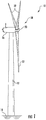
- FIG. 1 illustrates a side view of one embodiment of a wind turbine 10.
- the wind turbine 10 generally includes a tower 12 extending from a support surface 14 (e.g., the ground, a concrete pad or any other suitable support surface).
- the wind turbine 10 may also include a nacelle 16 mounted on the tower 12 and a rotor 18 coupled to the nacelle 16.
- the rotor 18 includes a rotatable hub 20 and at least one rotor blade 22 coupled to and extending outwardly from the hub 20.
- the rotor 18 includes three rotor blades 22.
- the rotor 18 may include more or less than three rotor blades 22.
- Each rotor blade 22 may be spaced about the hub 20 to facilitate rotating the rotor 18 to enable kinetic energy to be transferred from the wind into usable mechanical energy, and subsequently, electrical energy.
- the hub 20 may be rotatably coupled to an electric generator (not shown) positioned within the nacelle 16 to permit electrical energy to be produced.
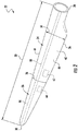
- FIGS. 2 and 3 one embodiment of a segmented rotor blade 22 suitable for use with the wind turbine 10 shown in FIG. 1 is illustrated in accordance with aspects of the present subject matter. Specifically, FIG. 2 illustrates a perspective, assembled view of the rotor blade 22 and FIG. 3 illustrates a perspective, exploded view of the rotor blade 22.
- the rotor blade 22 may generally be formed from a plurality of spanwise blade segments 24, 26 configured to be coupled end-to-end such that the rotor blade 22 extends between a blade root or root end 28 configured to be mounted or otherwise secured to the hub 20 ( FIG. 1 ) of the wind turbine 10 and a blade tip or tip end 30 disposed opposite the blade root 28.
- the rotor blade assembly 22 is formed from two blade segments 24, 26, namely a first blade segment 24 (e.g., a root segment) and a second blade segment 26 (e.g., a tip segment).
- the root segment 24 may generally extend lengthwise between the root end 28 and a first joint end 32.
- the tip segment 26 may generally extend lengthwise between the tip end 30 and a second joint end 34.
- the blade segments 24, 26 may generally be configured to be coupled to one another at their joint ends 32, 34.
- a blade joint 36 may be defined at the joint interface between the root and tip segments 24, 26.
- the rotor blade 22 may be formed from any other suitable number of spanwise blade segments.
- the rotor blade 22 may be formed from three blade segments or more than three blade segments, such as four blade segments, five blade segments, or more than five blade segments.
- each blade segment 24, 26 may include an outer shell 38, 40 configured to extend between the opposed ends of such segment that generally serves as the outer casing/covering of the blade segment 24, 26.
- the root segment 24 may include a first outer shell 38 ( FIG. 3 ) extending lengthwise between the root end 28 and the first joint end 32.
- the tip segment 26 may include a second outer shell 40 ( FIG. 3 ) extending lengthwise between the second joint end 34 and the tip end 30.
- Each of the outer shells 38, 40 may generally be configured to define spanwise sections of the aerodynamic profile of the rotor blade 22.
- the outer shells 38, 40 may collectively define a pressure side 42 and a suction side 44 of the rotor blade 22, with the pressure and suction sides 42, 44 extending between leading and trailing edges 46, 48 of the rotor blade 22.
- the rotor blade 22 when assembled, may also have a span 50 defining the total length between its root and tip ends 28, 30, with the span 50 generally corresponding to the summation of the combined spanwise lengths of the blade segments 24, 26.
- the root segment 24 may define a first spanwise length 52 ( FIG. 3 ) and the tip segment 26 may define a second spanwise length 54 ( FIG. 3 ).
- the rotor blade 22 may define a chord 56 ( FIG. 2 ) corresponding to the total length of the blade between its leading and trailing edges 46, 48.
- the chord 56 may generally vary in length with respect to the span 50 as the rotor blade 22 extends from the its root end 28 to its tip end 30.
- each outer shell 38, 40 of the blade segments 24, 26 may be formed from one or more shell components.
- each outer shell 38, 40 may be formed form a pressure side shell (not shown) forming a portion of the pressure side 42 of the rotor blade 22 and a suction side shell (not shown) forming a portion of the suction side 44 of the rotor blade 22.
- the outer shells 38, 40 may generally be formed from any suitable material.
- each outer shell 38, 40 may be formed from a fiber-reinforced composite, such as a fiber reinforced laminate including a plurality of fibers (e.g., glass or carbon fibers) surrounded by a suitable matrix material (e.g., a thermoset resin material or a thermoplastic resin material).
- a suitable matrix material e.g., a thermoset resin material or a thermoplastic resin material.
- one or more portions of each outer shell 38, 40 may be configured as a layered construction and may include a core material, formed from a lightweight material such as wood (e.g., balsa), foam (e.g., extruded polystyrene foam) or a combination of such materials, disposed between layers of laminate composite material.
- each blade segment 24, 26 may also include one or more internal structural components contained within its outer shell 38, 40 that is configured to provide increased stiffness, buckling resistance and/or strength to the rotor blade 22.
- the root segment 24 may include one or more internal structural components 58 extending within the first outer shell 38, such as by including one or more longitudinally extending structural components (e.g., a pair of opposed spar caps having a shear web extending therebetween) positioned within the first outer shell 38.
- the tip segment 26 may include one or more internal structural components 60 extending within the second outer shell 40, such as by including one or more longitudinally extending structural components (e.g., a pair of opposed spar caps having a shear web extending therebetween) positioned within the second outer shell 40.
- each blade segment 24, 26 may include one or more balance boxes 62, 64 installed within its interior.
- the root segment 24 may include a root balance box 62 while the tip segment 26 may include a tip balance box 64.
- Each balance box 62, 64 may generally correspond to an internal storage compartment or enclosed volume within each blade segment 24, 26 that provides a location for adding mass to the blade segment 24, 26. For instance, as will be described below, mass (e.g., a mixture of sand and resin) may be added to the balance box installed within root segment 24 and/or the tip segment 26 to adjust the static moment associated with the corresponding blade segment(s) 24, 26.
- mass e.g., a mixture of sand and resin
- each balance box 62, 64 may be installed within its corresponding blade segment 24, 26 at any suitable location along the segment's spanwise length 52, 54.
- each balance box 62, 64 may be positioned closer to the joint end 32, 34 of its corresponding blade segment 24, 26 than the opposed end of the blade segment 24, 26.
- each balance box 62, 64 may be located a distance 66 ( FIG.
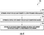
- FIG. 4 a flow diagram of one embodiment of a method 100 for balancing segmented rotor blades of a wind turbine is illustrated in accordance with aspects of the present subject matter.
- the method 100 will be described herein with reference to balancing the blade segments used to form two-piece rotor blades, such as the rotor blade 22 described above with reference to FIGS. 2 and 3 .
- the method 100 may be used to provide balanced rotor blades formed from any other suitable number of blade segments, such as three or more blade segments.
- the disclosed method 100 may be applied to balance a complete set of segmented rotor blades for use with a wind turbine.
- the complete set of segmented rotor blades 22 may include a set of three root segments 24 and a set of three tip segments 26.
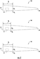
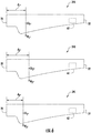
- the method 100 shown in FIG. 4 will be described particularly with reference to FIG. 5 , which illustrates a set of three tip segments 26, namely a first tip segment 26A, a second tip segment 26B, and a third segment 26C.
- the method 100 described herein may be similarly applied to a set of a root segments 24.
- the method 100 may include determining a weight for each blade segment of a given type/model being balanced (e.g., each tip segment 26 of a given configuration or each root segment 24 of a given configuration).
- the weight for each blade segment may be determined using any suitable means and/or methodology for weighing or otherwise calculating the weight of blade segments. For instance, in one embodiment, a scale or any other suitable weighing device may be used to determine the weight of each blade segment.
- the weight for each blade segment may be determined mathematically, such as by calculating the weight based on the dimensions of each blade segment and the properties of the material(s) used to form each blade segment.
- each of the tip segments 26A, 26B, 26C may be weighed or otherwise analyzed to determine its weight.
- the first tip segment 26A may have a first weight (Wi)
- the second tip segment 26B may have a second weight (W 2 )
- the third tip segment 26C may have a third weight (W 3 ).
- the weight of at least one of the tip segments 26A, 26B, 26C may differ from the weights of the remainder of the tip segments.
- each tip segment 26A, 26B, 26C may have a weight that differs from the weight of the other tip segments 26A, 26B, 26C at least slightly due to manufacturing tolerances and/or other limitations.
- each tip segment 26A, 26B, 26C may be represented by a center of gravity.
- the first tip segment 26A may define a first center of gravity (CGi)
- the second tip segment 26B may define a second center of gravity (CG 2 )
- the third tip segment 26C may define a third center of gravity (CG 3 ).
- the location of the center of gravity of at least one of the tip segments 26A, 26B, 26C may differ from the locations of the centers of gravity of the remainder of the tip segments.
- each tip segment 26A, 26B, 26C may have a center of gravity that is defined at a different location than the centers of gravity of the other tip segments due to manufacturing tolerances and/or other limitations.
- the method 100 may include determining an initial static moment for each blade segment being balanced.
- the static moment for a given blade segment may be determined as a function of its weight and the location of its center of gravity relative to a fixed reference point.
- the static moment for each tip segment 26A, 26B, 26C may be calculated based on the determined weight of each tip segment 26A, 26B, 26C and the distance defines between each tip segment's center of gravity and a fixed reference point (e.g., the joint end 34 of each tip segment 26A, 26B, 26C).
- the first tip segment 26A may define a first distance (d 1 ) between its joint end 34 and center of gravity (CG 1 )
- the second tip segment 26B may define a second distance (d 2 ) between its joint end 34 and center of gravity (CG 2 )
- the third tip segment 26C may define a third distance (d 3 ) between its joint end 34 and center of gravity (CG 3 ).
- the initial static moment of the first tip segment 26A may be calculated by multiplying its weight (W 1 ) by the first distance (d 1 ).
- the initial static moment of the second tip segment 26B may be calculated by multiplying its weight (W 2 ) by the second distance (d 2 ) while the initial static moment of the third tip segment 26C may be calculated by multiplying its weight (W 3 ) by the third distance (d 3 ).
- the initial static moment of at least one of the tip segments 26A, 26B, 26C may differ from the initial static moments of the remainder of the tip segments.
- each tip segment 26A, 26B, 26C may have an initial static moment that differs from the initial static moments of the other tip segments at least slightly due to manufacturing tolerances and/or other limitations.
- the method 100 may include adding mass to each of the plurality of blade segments to increase the initial static moment for each blade segment to a predetermined static moment.
- each blade segment may include a balance box 62, 64 within which mass may be added to adjust the static moment of the blade segment.
- mass may be added to adjust the static moment of the blade segment.
- a mixture of resin and sand may be used to create a thick slurry of material to be added within the balance box 62, 64 of each blade segment.
- any other suitable material(s) may be placed within the balance box 62, 64 of each blade segment to increase its mass and, thus, its corresponding static moment.
- mass may be added to each of the blade segments without requiring the use of a balance box.
- additional material(s) e.g., resins, adhesives, weights, etc.
- the predetermined static moment may correspond to a static moment that is greater than the initial static moment of each of the blade segments being balanced of a given type/model (e.g., a predetermined tip static moment that is greater than the initial static moment of each of the tip segments 26 being balanced and/or a predetermined root static moment that is greater than the initial static moment of each of the root segments 24 being balanced).
- each blade segment being balanced may require that mass be added to its balance box (or at any other suitable location(s)) to allow the initial static moment of the blade segment to be increased to the predetermined static moment.
- the predetermined static moment may be selected so as to correspond to a static moment that is greater than a maximum static moment allowed for a blade segment of a given type/model based on manufacturing tolerances and/or other limitations. For instance, based on allowable manufacturing variations, it may be determined that all or statistically all (e.g., 99.9%) of a given type/model of blade segment (e.g., a tip segment 26 or root segment 24) will have an initial static moment that is less than a given maximum static moment.
- a given type/model of blade segment e.g., a tip segment 26 or root segment 24
- the predetermined static moment may be set as the maximum static moment for such type/model of blade segment or the predetermined static moment may be set as a static moment that is greater than the maximum static moment (e.g., 1%-5% greater than the maximum static moment).
- the blade segments may be interchangeable with one another when assembling such blade segments with other blade segments to form a complete segmented rotor blade.
- the blade segments may be used to a form a balanced rotor set without the need for re-weighing or re-balancing the segments in the field and/or without requiring the blade segments to be specifically matched with other corresponding blade segments.
- mass may be added to the balance box 64 of each of the tip segments 26A, 26B, 26C to increase the initial static moment of each tip segment to a predetermined tip static moment.
- the initial static moments of the tip segments 26A, 26B, 26C may vary from segment-to-segment.
- a different amount of mass may need to be added to each tip segment 26A, 26B, 26C to increase its static moment to the predetermined tip static moment.
- FIG. 6 illustrates a set of three root segments, namely a first root segment 24A, a second root segment 24B, and a third root segment 24C.
- the first root segment 24A has a first weight (W 1* ) and defines a first distance (d 1* ) between its root end 28 and center of gravity (CG 1* ).
- the second root segment 24B has a second weight (W 2* ) and defines a second distance (d 2* ) between its root end 28 and center of gravity (CG 2* ).
- the third root segment 24C has a third weight (W 3* ) and defines a third distance (d 3* ) between its root end 28 and center of gravity (CG 3* ).
- the method 100 may be applied by determining both the weight of each root segment 24A, 24B, 24C and its corresponding initial static moment (e.g., as a function of the weight and the distance defined between the center of gravity and the segment's root end 28). Thereafter, mass may be added to each of the root segments 24A, 24B, 24C to increase the initial static moment of each root segment to a predetermined root static moment that is greater than the largest initial static moment of the root segments 24A, 24B, 24C.
- root segments are typically provided with larger allowable manufacturing variance ranges than tip segments, it may be desirable, in alternative embodiments, to set the predetermined root static moment based on the maximum initial static moment of the specific set of root segments being balanced as opposed to a static moment that exceeds the initial static moments of each of the root segments. For instance, when balancing the set of three root segments 24A, 24B, 24C shown in FIG. 6 , the weight and initial static moment of each root segment 24A, 24B, 24C may be determined. Thereafter, the root segment having the largest initial static moment may be identified, with its initial static moment being set as the predetermined root static moment for the remainder of the root segments. Mass may then be added to the other root segments to increase their initial static moments to the predetermined root static moment such that each root segment has the same static moment.
- each root segment 24A, 24B, 24C may be simply paired to a corresponding balanced tip segment (e.g., tip segments 26A, 26B, 26C) without the need to match the root segments to specific tip segments in attempt to create a balanced set of rotor blades for a given wind turbine.
- a corresponding balanced tip segment e.g., tip segments 26A, 26B, 26C
Landscapes
- Engineering & Computer Science (AREA)
- Life Sciences & Earth Sciences (AREA)
- Sustainable Development (AREA)
- Sustainable Energy (AREA)
- Chemical & Material Sciences (AREA)
- Combustion & Propulsion (AREA)
- Mechanical Engineering (AREA)
- General Engineering & Computer Science (AREA)
- Power Engineering (AREA)
- Physics & Mathematics (AREA)
- Fluid Mechanics (AREA)
- Wind Motors (AREA)
Claims (8)
- Verfahren (100) zum Auswuchten von segmentierten Rotorblättern (22) für eine Windturbine (10), wobei das Verfahren (100) umfasst:Bestimmen eines Gewichts für jedes von einer Vielzahl von Blattsegmenten (26), wobei sich jedes Blattsegment (26) zwischen einem ersten Ende (34) und einem zweiten Ende (30) erstreckt und konfiguriert ist, um eine gemeinsame Sektion in Spannweitenrichtung eines segmentierten Rotorblatts (22) zwischen dem ersten (34) und dem zweiten (30) Ende zu bilden;Bestimmen eines anfänglichen statischen Moments für jedes Blattsegment (26) basierend auf dem Gewicht des Blattsegments (26), wobei das anfängliche statische Moment von zumindest einem von den Blattsegmenten (26) von den anfänglichen statischen Momenten der Übrigen von der Vielzahl von Blattsegmenten (26) abweicht; undHinzufügen von Masse zu jedem von der Vielzahl von Blattsegmenten (26), um das anfängliche statische Moment für jedes Blattsegment (26) auf ein vorbestimmtes statisches Moment zu erhöhen, wobei das vorbestimmte statische Moment größer als jedes der anfänglichen statischen Momente der Vielzahl von Blattsegmenten (26) ist;wobei das vorbestimmte statische Moment einem statischen Moment entspricht, das gleich oder größer als ein maximales statisches Moment für die Vielzahl von Blattsegmenten (26) ist, basierend auf zulässigen Herstellungsschwankungen.
- Verfahren (100) nach Anspruch 1, wobei jedes Blattsegment (26) einem Spitzensegment (26) entspricht, wobei das erste Ende (34) einem Anschlussende (34) des Spitzensegments (26) entspricht und wobei das zweite Ende (30) einem Spitzenende (30) des Spitzensegments (26) entspricht, wobei das Anschlussende (34) konfiguriert ist, um mit einem entsprechenden Fußsegment (24) des segmentierten Rotorblatts (22) gekoppelt zu werden.
- Verfahren (100) nach einem vorstehenden Anspruch, wobei jedes Blattsegment (26) einem Fußsegment (24) entspricht, wobei das erste Ende (34) einem Fußende (28) des Fußsegments (24) entspricht und wobei das zweite Ende (30) einem Anschlussende (32) des Fußsegments (24) entspricht, wobei das Anschlussende (32) konfiguriert ist, um mit einem entsprechenden Spitzensegment (26) des segmentierten Rotorblatts (22) gekoppelt zu werden.
- Verfahren (100) nach einem vorstehenden Anspruch, weiter umfassend ein Bestimmen eines Schwerpunkts für jedes Blattsegment (26).
- Verfahren (100) nach Anspruch 4, wobei das Bestimmen des anfänglichen statischen Moments für jedes Blattsegment (26) ein Bestimmen des anfänglichen statischen Moments basierend auf dem Gewicht und dem Schwerpunkt für jedes Blattsegment (26) umfasst.
- Verfahren (100) nach einem vorstehenden Anspruch, wobei das Hinzufügen von Masse zu jedem von der Vielzahl von Blattsegmenten (26) ein Hinzufügen von Masse innerhalb einer Auswuchtungsbox (64), die innerhalb eines Inneren von jedem von der Vielzahl von Blattsegmenten (26) installiert ist, umfasst.
- Verfahren (100) nach einem vorstehenden Anspruch, wobei das erste Ende (34) von jedem von der Vielzahl von Blattsegmenten (26) einem Anschlussende (34) von jedem Blattsegment (26) entspricht und wobei jedes Blattsegment (26) eine Länge (54) in Spannweitenrichtung zwischen dem ersten Ende (34) und dem zweiten Ende (30) definiert, wobei sich die Auswuchtungsbox (64) innerhalb des Inneren von jedem Blattsegment (26) in einem Abstand (66) von dem Anschlussende (34), der gleich oder kleiner als 25% der Länge (54) in Spannweitenrichtung ist, befindet.
- Verfahren (100) nach einem vorstehenden Anspruch, wobei das anfängliche statische Moment von jedem Blattsegment (26) von den anfänglichen statischen Momenten der Übrigen von der Vielzahl von Blattsegmenten (26) abweicht.
Applications Claiming Priority (1)
| Application Number | Priority Date | Filing Date | Title |
|---|---|---|---|
| US15/232,900 US10550823B2 (en) | 2016-08-10 | 2016-08-10 | Method for balancing segmented wind turbine rotor blades |
Publications (2)
| Publication Number | Publication Date |
|---|---|
| EP3282121A1 EP3282121A1 (de) | 2018-02-14 |
| EP3282121B1 true EP3282121B1 (de) | 2019-02-27 |
Family
ID=59523029
Family Applications (1)
| Application Number | Title | Priority Date | Filing Date |
|---|---|---|---|
| EP17184806.2A Active EP3282121B1 (de) | 2016-08-10 | 2017-08-03 | Verfahren zum auswuchten von segmentierten windturbinenrotorblättern |
Country Status (3)
| Country | Link |
|---|---|
| US (1) | US10550823B2 (de) |
| EP (1) | EP3282121B1 (de) |
| CN (1) | CN107725268B (de) |
Families Citing this family (7)
| Publication number | Priority date | Publication date | Assignee | Title |
|---|---|---|---|---|
| EP3310568A4 (de) | 2015-06-22 | 2019-04-03 | Sikorsky Aircraft Corporation | Kernmaterial für verbundstrukturen |
| US10550823B2 (en) * | 2016-08-10 | 2020-02-04 | General Electric Company | Method for balancing segmented wind turbine rotor blades |
| US11548627B2 (en) * | 2016-08-15 | 2023-01-10 | Sikorsky Aircraft Corporation | Core matertal for balanced rotor blade |
| US11499529B2 (en) * | 2018-07-20 | 2022-11-15 | Vestas Wind Systems A/S | Method of balancing turbine blades |
| EP4211351A1 (de) * | 2020-09-09 | 2023-07-19 | Vestas Wind Systems A/S | Windturbinenschaufel |
| EP4027007A1 (de) * | 2021-01-12 | 2022-07-13 | General Electric Renovables España S.L. | Verfahren zur montage von schaufeln an einer rotornabe einer windturbine |
| EP4656872A1 (de) | 2024-05-28 | 2025-12-03 | Nederlandse Organisatie voor toegepast-natuurwetenschappelijk Onderzoek TNO | Windturbine mit hoher spitzenmasse und spannungselement |
Citations (6)
| Publication number | Priority date | Publication date | Assignee | Title |
|---|---|---|---|---|
| US20100170339A1 (en) | 2009-01-05 | 2010-07-08 | Michael Alfred Wilhelm Lenz | Method for balancing radical projections detached from a rotating assembly |
| EP2455611A2 (de) | 2010-11-18 | 2012-05-23 | Envision Energy (Denmark) ApS | Pitch-Regelungssystem mit Ausgleich für eine Windturbine |
| WO2015011292A1 (fr) | 2013-07-26 | 2015-01-29 | Societe Europeenne D'ingenierie Et De Developpement Des Energies Renouvelables | Pale d'eolienne segmentee et eolienne munie d'une telle pale |
| US20150082634A1 (en) | 2013-09-23 | 2015-03-26 | Sikorsky Aircraft Corporation | Method and apparatus for rotor blade balance |
| US20150110632A1 (en) | 2012-05-30 | 2015-04-23 | youWINenergy GmbH | Blade assembly for a wind turbine rotor |
| EP3034861A1 (de) | 2014-12-18 | 2016-06-22 | Acciona Windpower S.a. | Ausgleichsverfahren von Windturbinenrotoren |
Family Cites Families (46)
| Publication number | Priority date | Publication date | Assignee | Title |
|---|---|---|---|---|
| DE2528007C2 (de) * | 1975-06-24 | 1984-04-19 | Messerschmitt-Bölkow-Blohm GmbH, 8000 München | Verfahren zur Korrektur der Schwerpunktlage und des Gewichts von Rotorblättern |
| GB8529782D0 (en) | 1985-12-03 | 1986-01-08 | Orchard O J | Paying off fine material & fibres under constant tension |
| DE19962989B4 (de) * | 1999-12-24 | 2006-04-13 | Wobben, Aloys, Dipl.-Ing. | Rotorblatt für Windenergieanlagen |
| US6726439B2 (en) | 2001-08-22 | 2004-04-27 | Clipper Windpower Technology, Inc. | Retractable rotor blades for power generating wind and ocean current turbines and means for operating below set rotor torque limits |
| US6976829B2 (en) | 2003-07-16 | 2005-12-20 | Sikorsky Aircraft Corporation | Rotor blade tip section |
| JP2007198265A (ja) * | 2006-01-26 | 2007-08-09 | Kawasaki Heavy Ind Ltd | タービン動翼の配列方法 |
| US7654799B2 (en) | 2006-04-30 | 2010-02-02 | General Electric Company | Modular rotor blade for a wind turbine and method for assembling same |
| KR20090033905A (ko) | 2006-07-21 | 2009-04-06 | 클립퍼 윈드파워 테크놀로지 인코포레이티드 | 신축식 로터 블레이드 구조체 |
| ES2373421T3 (es) | 2008-01-14 | 2012-02-03 | Clipper Windpower, Llc | Una pala modular de rotor para una turbina generadora de energía y un método para ensamblar una turbina generadora de energía con palas modulares de rotor. |
| WO2009135902A2 (en) * | 2008-05-07 | 2009-11-12 | Vestas Wind Systems A/S | A sectional blade |
| DE102008045601A1 (de) * | 2008-06-27 | 2009-12-31 | Repower Systems Ag | Rotorblatt für eine Windenergieanlage und Verfahren und Fertigungform zu seiner Fertigung |
| US8497601B2 (en) * | 2008-09-27 | 2013-07-30 | Witricity Corporation | Wireless energy transfer converters |
| CA2650720A1 (en) * | 2009-01-22 | 2010-07-22 | Sharolyn Vettese | Rotating system balancing assembly |
| ES2389325T3 (es) * | 2009-03-25 | 2012-10-25 | Siemens Aktiengesellschaft | Disposición para determinar un momento estático de una pala |
| CN201420645Y (zh) * | 2009-06-03 | 2010-03-10 | 中船重工(重庆)海装风电设备有限公司 | 风力发电机的分段叶片 |
| EP2317124B1 (de) | 2009-10-01 | 2018-08-08 | Vestas Wind Systems A/S | Windturbinenschaufel |
| CN201593478U (zh) * | 2009-12-28 | 2010-09-29 | 浙江恒通机械有限公司 | 对接式风轮机叶片 |
| US8398374B2 (en) * | 2010-01-27 | 2013-03-19 | General Electric Company | Method and apparatus for a segmented turbine bucket assembly |
| EP2577051B1 (de) * | 2010-05-24 | 2018-10-24 | Vestas Wind Systems A/S | Segmentierte windkraftwerksrotorblätter mit gitterverbindungsbereichen sowie entsprechende systeme und verfahren |
| JP4939640B2 (ja) * | 2010-10-22 | 2012-05-30 | 三菱重工業株式会社 | 風車回転翼 |
| DK177278B1 (en) * | 2011-05-19 | 2012-09-17 | Envision Energy Denmark Aps | A wind turbine and associated control method |
| CN103857902A (zh) * | 2011-08-05 | 2014-06-11 | 泰克西斯先进技术及体系公司 | 风力发电机叶片末端区段以及组装的方法 |
| US20120141287A1 (en) * | 2011-08-29 | 2012-06-07 | General Electric Company | Wind turbine rotor blade joint |
| US8918997B2 (en) * | 2011-10-13 | 2014-12-30 | General Electric Company | Method for assembling a multi-segment wind turbine rotor blade with span-wise offset joints |
| DE102012209935A1 (de) * | 2011-12-08 | 2013-06-13 | Wobben Properties Gmbh | Hinterkasten, Rotorblatt mit Hinterkasten und Windenergieanlage mit solchem Rotorblatt |
| DE102011088025A1 (de) * | 2011-12-08 | 2013-06-13 | Wobben Properties Gmbh | Rotorblatt |
| DE102012201470A1 (de) * | 2012-02-01 | 2013-08-01 | Aktiebolaget Skf | Windkraftanlage |
| IN2012DE00572A (de) * | 2012-02-29 | 2015-06-05 | Gen Electric | |
| FR2989723B1 (fr) * | 2012-04-20 | 2024-02-09 | Astrium Sas | Assemblage de troncons de pieces structurables |
| US9394881B2 (en) * | 2013-05-29 | 2016-07-19 | Siemens Aktiengesellschaft | Wind turbine blade and method of fabricating a wind turbine blade |
| US9353729B2 (en) * | 2013-07-02 | 2016-05-31 | General Electric Company | Aerodynamic hub assembly for a wind turbine |
| US9605651B2 (en) * | 2013-12-04 | 2017-03-28 | General Electric Company | Spar assembly for a wind turbine rotor blade |
| DE102014204017A1 (de) * | 2014-03-05 | 2015-09-10 | Robert Bosch Gmbh | Verfahren und Vorrichtung zur Rotorblatteinstellung für eine Windkraftanlage |
| US20150369211A1 (en) * | 2014-06-19 | 2015-12-24 | General Electric Company | Wind blade tip joint |
| CN107667221B (zh) * | 2015-04-23 | 2019-11-05 | 远景能源(江苏)有限公司 | 校正转子不平衡的方法及其风力涡轮机 |
| US10533534B2 (en) * | 2015-09-09 | 2020-01-14 | General Electric Company | Composite layers for bonding components of a wind turbine rotor blade |
| US9951751B2 (en) * | 2015-09-30 | 2018-04-24 | General Electric Company | Segmented wind turbine rotor blade with rod and tube joint connection |
| US20170145986A1 (en) * | 2015-11-25 | 2017-05-25 | General Electric Company | Custom fit blade tip for a rotor blade assembly of a wind turbine and method of fabrication |
| DK3383658T3 (da) * | 2015-11-30 | 2022-09-19 | Vestas Wind Sys As | Vindmøller, vindmøllevinger, og fremgangsmåder til fremstilling af vindmøllevinger |
| US10760544B2 (en) * | 2016-06-20 | 2020-09-01 | General Electric Company | Sealing members for jointed rotor blade assemblies |
| US10550823B2 (en) * | 2016-08-10 | 2020-02-04 | General Electric Company | Method for balancing segmented wind turbine rotor blades |
| US20180051672A1 (en) * | 2016-08-19 | 2018-02-22 | General Electric Company | Jointed rotor blade for wind turbine |
| US20180118084A1 (en) * | 2016-10-27 | 2018-05-03 | Logisticus Projects Group | Turbine blade disposal system |
| US10723448B2 (en) * | 2016-11-14 | 2020-07-28 | Textron Innovations Inc. | Rotor blade weight system |
| DE102017206349B4 (de) * | 2017-04-12 | 2019-04-11 | Siemens Gamesa Renewable Energy A/S | Wiegevorrichtung für ein Windenergieanlagen-Rotorblatt |
| AU2018266819A1 (en) * | 2017-05-10 | 2019-12-05 | Gerald BARBER | Segmented airfoil design for guide wires |
-
2016
- 2016-08-10 US US15/232,900 patent/US10550823B2/en active Active
-
2017
- 2017-08-03 EP EP17184806.2A patent/EP3282121B1/de active Active
- 2017-08-10 CN CN201710680416.6A patent/CN107725268B/zh active Active
Patent Citations (6)
| Publication number | Priority date | Publication date | Assignee | Title |
|---|---|---|---|---|
| US20100170339A1 (en) | 2009-01-05 | 2010-07-08 | Michael Alfred Wilhelm Lenz | Method for balancing radical projections detached from a rotating assembly |
| EP2455611A2 (de) | 2010-11-18 | 2012-05-23 | Envision Energy (Denmark) ApS | Pitch-Regelungssystem mit Ausgleich für eine Windturbine |
| US20150110632A1 (en) | 2012-05-30 | 2015-04-23 | youWINenergy GmbH | Blade assembly for a wind turbine rotor |
| WO2015011292A1 (fr) | 2013-07-26 | 2015-01-29 | Societe Europeenne D'ingenierie Et De Developpement Des Energies Renouvelables | Pale d'eolienne segmentee et eolienne munie d'une telle pale |
| US20150082634A1 (en) | 2013-09-23 | 2015-03-26 | Sikorsky Aircraft Corporation | Method and apparatus for rotor blade balance |
| EP3034861A1 (de) | 2014-12-18 | 2016-06-22 | Acciona Windpower S.a. | Ausgleichsverfahren von Windturbinenrotoren |
Also Published As
| Publication number | Publication date |
|---|---|
| EP3282121A1 (de) | 2018-02-14 |
| US20180045174A1 (en) | 2018-02-15 |
| US10550823B2 (en) | 2020-02-04 |
| CN107725268A (zh) | 2018-02-23 |
| CN107725268B (zh) | 2021-03-16 |
Similar Documents
| Publication | Publication Date | Title |
|---|---|---|
| EP3282121B1 (de) | Verfahren zum auswuchten von segmentierten windturbinenrotorblättern | |
| Kong et al. | Structural investigation of composite wind turbine blade considering various load cases and fatigue life | |
| US10273935B2 (en) | Rotor blades having structural skin insert and methods of making same | |
| US10760545B2 (en) | Joint configuration for a segmented wind turbine rotor blade | |
| US8186964B2 (en) | Spar assembly for a wind turbine rotor blade | |
| EP2402594A1 (de) | Windturbinenschaufel für einen Rotor einer Windturbine | |
| CN101397973B (zh) | 带有连接的抗剪腹板的风力涡轮机翼梁 | |
| US8753092B2 (en) | Rotor blade for a wind turbine and methods of manufacturing the same | |
| EP2981708B1 (de) | Schaufeleinsatz für ein rotorblatt einer windenergieanlage | |
| DK178020B1 (da) | Spar cap-enhed til en vindmøllerotorvinge | |
| DK178162B9 (en) | Methods of manufacturing rotor blades for a wind turbine | |
| EP3599374B1 (de) | Windturbinenrotorblatt mir einem verbundmaterial und verfahren zur herstellung eines windturbinenrotorblatts | |
| EP2159414B1 (de) | Windturbinenschaufeln mit Quernetzen | |
| EP2728169A2 (de) | Strukturelemente für eine Windturbinenlaufschaufel | |
| JP2022509397A (ja) | セグメント化された風力タービンブレードの製造 | |
| EP3032094B1 (de) | Holmkappe für ein windturbinenrotorblatt | |
| GB2484107A (en) | Modular wind turbine blade for a vertical axis wind turbine | |
| Kong et al. | Structural design of medium scale composite wind turbine blade | |
| US12503996B2 (en) | Wind turbine blade with leeward reinforcement structures and windward reinforcement structures | |
| KR101187302B1 (ko) | 윙박스로 경량화된 풍력 발전 장치용 블레이드, 윙박스 제조공구 및 제조방법 | |
| US20120027611A1 (en) | Compression member for wind turbine rotor blades | |
| US12203443B2 (en) | Wind turbine blade | |
| RU2209339C1 (ru) | Лопасть ветроколеса | |
| CN103597204B (zh) | 包括根部端隔板的风力涡轮机叶片 | |
| CN113631810A (zh) | 在风力涡轮机叶片的叶片区段上执行后模制操作 |
Legal Events
| Date | Code | Title | Description |
|---|---|---|---|
| PUAI | Public reference made under article 153(3) epc to a published international application that has entered the european phase |
Free format text: ORIGINAL CODE: 0009012 |
|
| STAA | Information on the status of an ep patent application or granted ep patent |
Free format text: STATUS: THE APPLICATION HAS BEEN PUBLISHED |
|
| AK | Designated contracting states |
Kind code of ref document: A1 Designated state(s): AL AT BE BG CH CY CZ DE DK EE ES FI FR GB GR HR HU IE IS IT LI LT LU LV MC MK MT NL NO PL PT RO RS SE SI SK SM TR |
|
| AX | Request for extension of the european patent |
Extension state: BA ME |
|
| STAA | Information on the status of an ep patent application or granted ep patent |
Free format text: STATUS: REQUEST FOR EXAMINATION WAS MADE |
|
| 17P | Request for examination filed |
Effective date: 20180814 |
|
| RBV | Designated contracting states (corrected) |
Designated state(s): AL AT BE BG CH CY CZ DE DK EE ES FI FR GB GR HR HU IE IS IT LI LT LU LV MC MK MT NL NO PL PT RO RS SE SI SK SM TR |
|
| GRAP | Despatch of communication of intention to grant a patent |
Free format text: ORIGINAL CODE: EPIDOSNIGR1 |
|
| STAA | Information on the status of an ep patent application or granted ep patent |
Free format text: STATUS: GRANT OF PATENT IS INTENDED |
|
| INTG | Intention to grant announced |
Effective date: 20181012 |
|
| GRAS | Grant fee paid |
Free format text: ORIGINAL CODE: EPIDOSNIGR3 |
|
| GRAA | (expected) grant |
Free format text: ORIGINAL CODE: 0009210 |
|
| STAA | Information on the status of an ep patent application or granted ep patent |
Free format text: STATUS: THE PATENT HAS BEEN GRANTED |
|
| AK | Designated contracting states |
Kind code of ref document: B1 Designated state(s): AL AT BE BG CH CY CZ DE DK EE ES FI FR GB GR HR HU IE IS IT LI LT LU LV MC MK MT NL NO PL PT RO RS SE SI SK SM TR |
|
| REG | Reference to a national code |
Ref country code: GB Ref legal event code: FG4D |
|
| REG | Reference to a national code |
Ref country code: CH Ref legal event code: EP |
|
| REG | Reference to a national code |
Ref country code: AT Ref legal event code: REF Ref document number: 1101725 Country of ref document: AT Kind code of ref document: T Effective date: 20190315 |
|
| REG | Reference to a national code |
Ref country code: IE Ref legal event code: FG4D |
|
| REG | Reference to a national code |
Ref country code: DE Ref legal event code: R096 Ref document number: 602017002343 Country of ref document: DE |
|
| REG | Reference to a national code |
Ref country code: NL Ref legal event code: MP Effective date: 20190227 |
|
| REG | Reference to a national code |
Ref country code: LT Ref legal event code: MG4D |
|
| PG25 | Lapsed in a contracting state [announced via postgrant information from national office to epo] |
Ref country code: FI Free format text: LAPSE BECAUSE OF FAILURE TO SUBMIT A TRANSLATION OF THE DESCRIPTION OR TO PAY THE FEE WITHIN THE PRESCRIBED TIME-LIMIT Effective date: 20190227 Ref country code: LT Free format text: LAPSE BECAUSE OF FAILURE TO SUBMIT A TRANSLATION OF THE DESCRIPTION OR TO PAY THE FEE WITHIN THE PRESCRIBED TIME-LIMIT Effective date: 20190227 Ref country code: SE Free format text: LAPSE BECAUSE OF FAILURE TO SUBMIT A TRANSLATION OF THE DESCRIPTION OR TO PAY THE FEE WITHIN THE PRESCRIBED TIME-LIMIT Effective date: 20190227 Ref country code: NL Free format text: LAPSE BECAUSE OF FAILURE TO SUBMIT A TRANSLATION OF THE DESCRIPTION OR TO PAY THE FEE WITHIN THE PRESCRIBED TIME-LIMIT Effective date: 20190227 Ref country code: NO Free format text: LAPSE BECAUSE OF FAILURE TO SUBMIT A TRANSLATION OF THE DESCRIPTION OR TO PAY THE FEE WITHIN THE PRESCRIBED TIME-LIMIT Effective date: 20190527 Ref country code: PT Free format text: LAPSE BECAUSE OF FAILURE TO SUBMIT A TRANSLATION OF THE DESCRIPTION OR TO PAY THE FEE WITHIN THE PRESCRIBED TIME-LIMIT Effective date: 20190627 |
|
| PG25 | Lapsed in a contracting state [announced via postgrant information from national office to epo] |
Ref country code: IS Free format text: LAPSE BECAUSE OF FAILURE TO SUBMIT A TRANSLATION OF THE DESCRIPTION OR TO PAY THE FEE WITHIN THE PRESCRIBED TIME-LIMIT Effective date: 20190627 Ref country code: RS Free format text: LAPSE BECAUSE OF FAILURE TO SUBMIT A TRANSLATION OF THE DESCRIPTION OR TO PAY THE FEE WITHIN THE PRESCRIBED TIME-LIMIT Effective date: 20190227 Ref country code: GR Free format text: LAPSE BECAUSE OF FAILURE TO SUBMIT A TRANSLATION OF THE DESCRIPTION OR TO PAY THE FEE WITHIN THE PRESCRIBED TIME-LIMIT Effective date: 20190528 Ref country code: BG Free format text: LAPSE BECAUSE OF FAILURE TO SUBMIT A TRANSLATION OF THE DESCRIPTION OR TO PAY THE FEE WITHIN THE PRESCRIBED TIME-LIMIT Effective date: 20190527 Ref country code: HR Free format text: LAPSE BECAUSE OF FAILURE TO SUBMIT A TRANSLATION OF THE DESCRIPTION OR TO PAY THE FEE WITHIN THE PRESCRIBED TIME-LIMIT Effective date: 20190227 Ref country code: LV Free format text: LAPSE BECAUSE OF FAILURE TO SUBMIT A TRANSLATION OF THE DESCRIPTION OR TO PAY THE FEE WITHIN THE PRESCRIBED TIME-LIMIT Effective date: 20190227 |
|
| REG | Reference to a national code |
Ref country code: AT Ref legal event code: MK05 Ref document number: 1101725 Country of ref document: AT Kind code of ref document: T Effective date: 20190227 |
|
| PG25 | Lapsed in a contracting state [announced via postgrant information from national office to epo] |
Ref country code: CZ Free format text: LAPSE BECAUSE OF FAILURE TO SUBMIT A TRANSLATION OF THE DESCRIPTION OR TO PAY THE FEE WITHIN THE PRESCRIBED TIME-LIMIT Effective date: 20190227 Ref country code: SK Free format text: LAPSE BECAUSE OF FAILURE TO SUBMIT A TRANSLATION OF THE DESCRIPTION OR TO PAY THE FEE WITHIN THE PRESCRIBED TIME-LIMIT Effective date: 20190227 Ref country code: IT Free format text: LAPSE BECAUSE OF FAILURE TO SUBMIT A TRANSLATION OF THE DESCRIPTION OR TO PAY THE FEE WITHIN THE PRESCRIBED TIME-LIMIT Effective date: 20190227 Ref country code: RO Free format text: LAPSE BECAUSE OF FAILURE TO SUBMIT A TRANSLATION OF THE DESCRIPTION OR TO PAY THE FEE WITHIN THE PRESCRIBED TIME-LIMIT Effective date: 20190227 Ref country code: EE Free format text: LAPSE BECAUSE OF FAILURE TO SUBMIT A TRANSLATION OF THE DESCRIPTION OR TO PAY THE FEE WITHIN THE PRESCRIBED TIME-LIMIT Effective date: 20190227 Ref country code: AL Free format text: LAPSE BECAUSE OF FAILURE TO SUBMIT A TRANSLATION OF THE DESCRIPTION OR TO PAY THE FEE WITHIN THE PRESCRIBED TIME-LIMIT Effective date: 20190227 Ref country code: ES Free format text: LAPSE BECAUSE OF FAILURE TO SUBMIT A TRANSLATION OF THE DESCRIPTION OR TO PAY THE FEE WITHIN THE PRESCRIBED TIME-LIMIT Effective date: 20190227 Ref country code: DK Free format text: LAPSE BECAUSE OF FAILURE TO SUBMIT A TRANSLATION OF THE DESCRIPTION OR TO PAY THE FEE WITHIN THE PRESCRIBED TIME-LIMIT Effective date: 20190227 |
|
| REG | Reference to a national code |
Ref country code: DE Ref legal event code: R026 Ref document number: 602017002343 Country of ref document: DE |
|
| PG25 | Lapsed in a contracting state [announced via postgrant information from national office to epo] |
Ref country code: PL Free format text: LAPSE BECAUSE OF FAILURE TO SUBMIT A TRANSLATION OF THE DESCRIPTION OR TO PAY THE FEE WITHIN THE PRESCRIBED TIME-LIMIT Effective date: 20190227 Ref country code: SM Free format text: LAPSE BECAUSE OF FAILURE TO SUBMIT A TRANSLATION OF THE DESCRIPTION OR TO PAY THE FEE WITHIN THE PRESCRIBED TIME-LIMIT Effective date: 20190227 |
|
| PLBI | Opposition filed |
Free format text: ORIGINAL CODE: 0009260 |
|
| PLAX | Notice of opposition and request to file observation + time limit sent |
Free format text: ORIGINAL CODE: EPIDOSNOBS2 |
|
| PG25 | Lapsed in a contracting state [announced via postgrant information from national office to epo] |
Ref country code: AT Free format text: LAPSE BECAUSE OF FAILURE TO SUBMIT A TRANSLATION OF THE DESCRIPTION OR TO PAY THE FEE WITHIN THE PRESCRIBED TIME-LIMIT Effective date: 20190227 |
|
| 26 | Opposition filed |
Opponent name: SIEMENS GAMESA RENEWABLE ENERGY GMBH & CO. KG Effective date: 20191126 |
|
| PG25 | Lapsed in a contracting state [announced via postgrant information from national office to epo] |
Ref country code: SI Free format text: LAPSE BECAUSE OF FAILURE TO SUBMIT A TRANSLATION OF THE DESCRIPTION OR TO PAY THE FEE WITHIN THE PRESCRIBED TIME-LIMIT Effective date: 20190227 |
|
| PG25 | Lapsed in a contracting state [announced via postgrant information from national office to epo] |
Ref country code: TR Free format text: LAPSE BECAUSE OF FAILURE TO SUBMIT A TRANSLATION OF THE DESCRIPTION OR TO PAY THE FEE WITHIN THE PRESCRIBED TIME-LIMIT Effective date: 20190227 |
|
| PLBB | Reply of patent proprietor to notice(s) of opposition received |
Free format text: ORIGINAL CODE: EPIDOSNOBS3 |
|
| PG25 | Lapsed in a contracting state [announced via postgrant information from national office to epo] |
Ref country code: LU Free format text: LAPSE BECAUSE OF NON-PAYMENT OF DUE FEES Effective date: 20190803 Ref country code: MC Free format text: LAPSE BECAUSE OF FAILURE TO SUBMIT A TRANSLATION OF THE DESCRIPTION OR TO PAY THE FEE WITHIN THE PRESCRIBED TIME-LIMIT Effective date: 20190227 |
|
| REG | Reference to a national code |
Ref country code: BE Ref legal event code: MM Effective date: 20190831 |
|
| PG25 | Lapsed in a contracting state [announced via postgrant information from national office to epo] |
Ref country code: FR Free format text: LAPSE BECAUSE OF NON-PAYMENT OF DUE FEES Effective date: 20190831 Ref country code: IE Free format text: LAPSE BECAUSE OF NON-PAYMENT OF DUE FEES Effective date: 20190803 |
|
| PG25 | Lapsed in a contracting state [announced via postgrant information from national office to epo] |
Ref country code: BE Free format text: LAPSE BECAUSE OF NON-PAYMENT OF DUE FEES Effective date: 20190831 |
|
| PLCK | Communication despatched that opposition was rejected |
Free format text: ORIGINAL CODE: EPIDOSNREJ1 |
|
| PLAG | Information modified related to despatch of communication that opposition is rejected |
Free format text: ORIGINAL CODE: EPIDOSCREJ1 |
|
| REG | Reference to a national code |
Ref country code: CH Ref legal event code: PL |
|
| PG25 | Lapsed in a contracting state [announced via postgrant information from national office to epo] |
Ref country code: CH Free format text: LAPSE BECAUSE OF NON-PAYMENT OF DUE FEES Effective date: 20200831 Ref country code: LI Free format text: LAPSE BECAUSE OF NON-PAYMENT OF DUE FEES Effective date: 20200831 |
|
| PG25 | Lapsed in a contracting state [announced via postgrant information from national office to epo] |
Ref country code: CY Free format text: LAPSE BECAUSE OF FAILURE TO SUBMIT A TRANSLATION OF THE DESCRIPTION OR TO PAY THE FEE WITHIN THE PRESCRIBED TIME-LIMIT Effective date: 20190227 |
|
| APAH | Appeal reference modified |
Free format text: ORIGINAL CODE: EPIDOSCREFNO |
|
| APBM | Appeal reference recorded |
Free format text: ORIGINAL CODE: EPIDOSNREFNO |
|
| APBP | Date of receipt of notice of appeal recorded |
Free format text: ORIGINAL CODE: EPIDOSNNOA2O |
|
| REG | Reference to a national code |
Ref country code: DE Ref legal event code: R100 Ref document number: 602017002343 Country of ref document: DE |
|
| PG25 | Lapsed in a contracting state [announced via postgrant information from national office to epo] |
Ref country code: HU Free format text: LAPSE BECAUSE OF FAILURE TO SUBMIT A TRANSLATION OF THE DESCRIPTION OR TO PAY THE FEE WITHIN THE PRESCRIBED TIME-LIMIT; INVALID AB INITIO Effective date: 20170803 Ref country code: MT Free format text: LAPSE BECAUSE OF FAILURE TO SUBMIT A TRANSLATION OF THE DESCRIPTION OR TO PAY THE FEE WITHIN THE PRESCRIBED TIME-LIMIT Effective date: 20190227 |
|
| APBU | Appeal procedure closed |
Free format text: ORIGINAL CODE: EPIDOSNNOA9O |
|
| PLBN | Opposition rejected |
Free format text: ORIGINAL CODE: 0009273 |
|
| STAA | Information on the status of an ep patent application or granted ep patent |
Free format text: STATUS: OPPOSITION REJECTED |
|
| 27O | Opposition rejected |
Effective date: 20210729 |
|
| GBPC | Gb: european patent ceased through non-payment of renewal fee |
Effective date: 20210803 |
|
| PG25 | Lapsed in a contracting state [announced via postgrant information from national office to epo] |
Ref country code: MK Free format text: LAPSE BECAUSE OF FAILURE TO SUBMIT A TRANSLATION OF THE DESCRIPTION OR TO PAY THE FEE WITHIN THE PRESCRIBED TIME-LIMIT Effective date: 20190227 |
|
| PG25 | Lapsed in a contracting state [announced via postgrant information from national office to epo] |
Ref country code: GB Free format text: LAPSE BECAUSE OF NON-PAYMENT OF DUE FEES Effective date: 20210803 |
|
| P01 | Opt-out of the competence of the unified patent court (upc) registered |
Effective date: 20230522 |
|
| REG | Reference to a national code |
Ref country code: DE Ref legal event code: R082 Ref document number: 602017002343 Country of ref document: DE Ref country code: DE Ref legal event code: R081 Ref document number: 602017002343 Country of ref document: DE Owner name: GENERAL ELECTRIC RENOVABLES ESPANA S.L., ES Free format text: FORMER OWNER: GENERAL ELECTRIC COMPANY, SCHENECTADY, NY, US Ref country code: DE Ref legal event code: R081 Ref document number: 602017002343 Country of ref document: DE Owner name: LM WIND POWER A/S, DK Free format text: FORMER OWNER: GENERAL ELECTRIC COMPANY, SCHENECTADY, NY, US Ref country code: DE Ref legal event code: R082 Ref document number: 602017002343 Country of ref document: DE Representative=s name: ZIMMERMANN & PARTNER PATENTANWAELTE MBB, DE |
|
| REG | Reference to a national code |
Ref country code: DE Ref legal event code: R082 Ref document number: 602017002343 Country of ref document: DE Representative=s name: ZIMMERMANN & PARTNER PATENTANWAELTE MBB, DE |
|
| REG | Reference to a national code |
Ref country code: DE Ref legal event code: R082 Ref document number: 602017002343 Country of ref document: DE Ref country code: DE Ref legal event code: R081 Ref document number: 602017002343 Country of ref document: DE Owner name: GENERAL ELECTRIC RENOVABLES ESPANA S.L., ES Free format text: FORMER OWNER: LM WIND POWER A/S, KOLDING, DK |
|
| PGFP | Annual fee paid to national office [announced via postgrant information from national office to epo] |
Ref country code: DE Payment date: 20250724 Year of fee payment: 9 |