EP3282092A1 - Turbofan engine with cladding having a separate closing element and lying in the secondary flow channel - Google Patents
Turbofan engine with cladding having a separate closing element and lying in the secondary flow channel Download PDFInfo
- Publication number
- EP3282092A1 EP3282092A1 EP17183952.5A EP17183952A EP3282092A1 EP 3282092 A1 EP3282092 A1 EP 3282092A1 EP 17183952 A EP17183952 A EP 17183952A EP 3282092 A1 EP3282092 A1 EP 3282092A1
- Authority
- EP
- European Patent Office
- Prior art keywords
- receiving body
- locking
- turbofan engine
- closing element
- flow channel
- Prior art date
- Legal status (The legal status is an assumption and is not a legal conclusion. Google has not performed a legal analysis and makes no representation as to the accuracy of the status listed.)
- Granted
Links
- 238000005253 cladding Methods 0.000 title description 18
- 239000012530 fluid Substances 0.000 claims abstract description 31
- 230000007246 mechanism Effects 0.000 claims description 42
- 125000006850 spacer group Chemical group 0.000 claims description 36
- 238000006073 displacement reaction Methods 0.000 claims description 8
- 230000006835 compression Effects 0.000 description 8
- 238000007906 compression Methods 0.000 description 8
- 238000003780 insertion Methods 0.000 description 6
- 230000037431 insertion Effects 0.000 description 6
- 239000000463 material Substances 0.000 description 6
- 230000008878 coupling Effects 0.000 description 5
- 238000010168 coupling process Methods 0.000 description 5
- 238000005859 coupling reaction Methods 0.000 description 5
- 238000002485 combustion reaction Methods 0.000 description 4
- 238000011161 development Methods 0.000 description 4
- 230000002349 favourable effect Effects 0.000 description 3
- 239000000446 fuel Substances 0.000 description 3
- 230000009471 action Effects 0.000 description 2
- 230000009172 bursting Effects 0.000 description 2
- 238000001816 cooling Methods 0.000 description 2
- 230000009970 fire resistant effect Effects 0.000 description 2
- 230000005012 migration Effects 0.000 description 2
- 238000013508 migration Methods 0.000 description 2
- 230000008439 repair process Effects 0.000 description 2
- 238000005452 bending Methods 0.000 description 1
- 239000003795 chemical substances by application Substances 0.000 description 1
- 239000002131 composite material Substances 0.000 description 1
- 239000006258 conductive agent Substances 0.000 description 1
- 238000013461 design Methods 0.000 description 1
- 239000003733 fiber-reinforced composite Substances 0.000 description 1
- 239000007789 gas Substances 0.000 description 1
- 239000007788 liquid Substances 0.000 description 1
- 238000012423 maintenance Methods 0.000 description 1
- 239000004033 plastic Substances 0.000 description 1
- 230000001681 protective effect Effects 0.000 description 1
- 230000003716 rejuvenation Effects 0.000 description 1
- 239000013589 supplement Substances 0.000 description 1
- 238000003466 welding Methods 0.000 description 1
Images


Classifications
-
- B—PERFORMING OPERATIONS; TRANSPORTING
- B64—AIRCRAFT; AVIATION; COSMONAUTICS
- B64D—EQUIPMENT FOR FITTING IN OR TO AIRCRAFT; FLIGHT SUITS; PARACHUTES; ARRANGEMENTS OR MOUNTING OF POWER PLANTS OR PROPULSION TRANSMISSIONS IN AIRCRAFT
- B64D29/00—Power-plant nacelles, fairings, or cowlings
- B64D29/06—Attaching of nacelles, fairings or cowlings
-
- F—MECHANICAL ENGINEERING; LIGHTING; HEATING; WEAPONS; BLASTING
- F01—MACHINES OR ENGINES IN GENERAL; ENGINE PLANTS IN GENERAL; STEAM ENGINES
- F01D—NON-POSITIVE DISPLACEMENT MACHINES OR ENGINES, e.g. STEAM TURBINES
- F01D9/00—Stators
- F01D9/06—Fluid supply conduits to nozzles or the like
- F01D9/065—Fluid supply or removal conduits traversing the working fluid flow, e.g. for lubrication-, cooling-, or sealing fluids
-
- F—MECHANICAL ENGINEERING; LIGHTING; HEATING; WEAPONS; BLASTING
- F01—MACHINES OR ENGINES IN GENERAL; ENGINE PLANTS IN GENERAL; STEAM ENGINES
- F01D—NON-POSITIVE DISPLACEMENT MACHINES OR ENGINES, e.g. STEAM TURBINES
- F01D9/00—Stators
- F01D9/02—Nozzles; Nozzle boxes; Stator blades; Guide conduits, e.g. individual nozzles
-
- F—MECHANICAL ENGINEERING; LIGHTING; HEATING; WEAPONS; BLASTING
- F02—COMBUSTION ENGINES; HOT-GAS OR COMBUSTION-PRODUCT ENGINE PLANTS
- F02C—GAS-TURBINE PLANTS; AIR INTAKES FOR JET-PROPULSION PLANTS; CONTROLLING FUEL SUPPLY IN AIR-BREATHING JET-PROPULSION PLANTS
- F02C7/00—Features, components parts, details or accessories, not provided for in, or of interest apart form groups F02C1/00 - F02C6/00; Air intakes for jet-propulsion plants
- F02C7/04—Air intakes for gas-turbine plants or jet-propulsion plants
-
- F—MECHANICAL ENGINEERING; LIGHTING; HEATING; WEAPONS; BLASTING
- F02—COMBUSTION ENGINES; HOT-GAS OR COMBUSTION-PRODUCT ENGINE PLANTS
- F02K—JET-PROPULSION PLANTS
- F02K1/00—Plants characterised by the form or arrangement of the jet pipe or nozzle; Jet pipes or nozzles peculiar thereto
- F02K1/52—Nozzles specially constructed for positioning adjacent to another nozzle or to a fixed member, e.g. fairing
-
- F—MECHANICAL ENGINEERING; LIGHTING; HEATING; WEAPONS; BLASTING
- F02—COMBUSTION ENGINES; HOT-GAS OR COMBUSTION-PRODUCT ENGINE PLANTS
- F02K—JET-PROPULSION PLANTS
- F02K3/00—Plants including a gas turbine driving a compressor or a ducted fan
- F02K3/02—Plants including a gas turbine driving a compressor or a ducted fan in which part of the working fluid by-passes the turbine and combustion chamber
- F02K3/04—Plants including a gas turbine driving a compressor or a ducted fan in which part of the working fluid by-passes the turbine and combustion chamber the plant including ducted fans, i.e. fans with high volume, low pressure outputs, for augmenting the jet thrust, e.g. of double-flow type
- F02K3/06—Plants including a gas turbine driving a compressor or a ducted fan in which part of the working fluid by-passes the turbine and combustion chamber the plant including ducted fans, i.e. fans with high volume, low pressure outputs, for augmenting the jet thrust, e.g. of double-flow type with front fan
-
- F—MECHANICAL ENGINEERING; LIGHTING; HEATING; WEAPONS; BLASTING
- F01—MACHINES OR ENGINES IN GENERAL; ENGINE PLANTS IN GENERAL; STEAM ENGINES
- F01D—NON-POSITIVE DISPLACEMENT MACHINES OR ENGINES, e.g. STEAM TURBINES
- F01D25/00—Component parts, details, or accessories, not provided for in, or of interest apart from, other groups
- F01D25/28—Supporting or mounting arrangements, e.g. for turbine casing
-
- F—MECHANICAL ENGINEERING; LIGHTING; HEATING; WEAPONS; BLASTING
- F05—INDEXING SCHEMES RELATING TO ENGINES OR PUMPS IN VARIOUS SUBCLASSES OF CLASSES F01-F04
- F05D—INDEXING SCHEME FOR ASPECTS RELATING TO NON-POSITIVE-DISPLACEMENT MACHINES OR ENGINES, GAS-TURBINES OR JET-PROPULSION PLANTS
- F05D2230/00—Manufacture
- F05D2230/60—Assembly methods
- F05D2230/64—Assembly methods using positioning or alignment devices for aligning or centring, e.g. pins
-
- F—MECHANICAL ENGINEERING; LIGHTING; HEATING; WEAPONS; BLASTING
- F05—INDEXING SCHEMES RELATING TO ENGINES OR PUMPS IN VARIOUS SUBCLASSES OF CLASSES F01-F04
- F05D—INDEXING SCHEME FOR ASPECTS RELATING TO NON-POSITIVE-DISPLACEMENT MACHINES OR ENGINES, GAS-TURBINES OR JET-PROPULSION PLANTS
- F05D2230/00—Manufacture
- F05D2230/70—Disassembly methods
-
- F—MECHANICAL ENGINEERING; LIGHTING; HEATING; WEAPONS; BLASTING
- F05—INDEXING SCHEMES RELATING TO ENGINES OR PUMPS IN VARIOUS SUBCLASSES OF CLASSES F01-F04
- F05D—INDEXING SCHEME FOR ASPECTS RELATING TO NON-POSITIVE-DISPLACEMENT MACHINES OR ENGINES, GAS-TURBINES OR JET-PROPULSION PLANTS
- F05D2240/00—Components
- F05D2240/10—Stators
- F05D2240/12—Fluid guiding means, e.g. vanes
- F05D2240/121—Fluid guiding means, e.g. vanes related to the leading edge of a stator vane
-
- F—MECHANICAL ENGINEERING; LIGHTING; HEATING; WEAPONS; BLASTING
- F05—INDEXING SCHEMES RELATING TO ENGINES OR PUMPS IN VARIOUS SUBCLASSES OF CLASSES F01-F04
- F05D—INDEXING SCHEME FOR ASPECTS RELATING TO NON-POSITIVE-DISPLACEMENT MACHINES OR ENGINES, GAS-TURBINES OR JET-PROPULSION PLANTS
- F05D2240/00—Components
- F05D2240/10—Stators
- F05D2240/12—Fluid guiding means, e.g. vanes
- F05D2240/122—Fluid guiding means, e.g. vanes related to the trailing edge of a stator vane
-
- F—MECHANICAL ENGINEERING; LIGHTING; HEATING; WEAPONS; BLASTING
- F05—INDEXING SCHEMES RELATING TO ENGINES OR PUMPS IN VARIOUS SUBCLASSES OF CLASSES F01-F04
- F05D—INDEXING SCHEME FOR ASPECTS RELATING TO NON-POSITIVE-DISPLACEMENT MACHINES OR ENGINES, GAS-TURBINES OR JET-PROPULSION PLANTS
- F05D2260/00—Function
- F05D2260/30—Retaining components in desired mutual position
- F05D2260/36—Retaining components in desired mutual position by a form fit connection, e.g. by interlocking
-
- F—MECHANICAL ENGINEERING; LIGHTING; HEATING; WEAPONS; BLASTING
- F05—INDEXING SCHEMES RELATING TO ENGINES OR PUMPS IN VARIOUS SUBCLASSES OF CLASSES F01-F04
- F05D—INDEXING SCHEME FOR ASPECTS RELATING TO NON-POSITIVE-DISPLACEMENT MACHINES OR ENGINES, GAS-TURBINES OR JET-PROPULSION PLANTS
- F05D2260/00—Function
- F05D2260/30—Retaining components in desired mutual position
- F05D2260/38—Retaining components in desired mutual position by a spring, i.e. spring loaded or biased towards a certain position
Definitions
- the invention relates to a turbofan engine according to the preamble of claim 1.
- Turbofan engines are also referred to as bypass or bypass engines. They are distinguished by the fact that the fan (also referred to as fan) is driven by a turbine arranged behind the combustion chamber of the turbofan engine, wherein a large proportion of the air mass drawn in by the engine is accelerated past a core engine having the combustion chamber.
- the turbofan engine forms a primary flow channel through the core engine and a secondary flow channel for an external fluid flow, which is guided past the core engine.
- the turbofan engine and in particular through the secondary flow channel are different components, such as cables, struts or adjustable coupling elements laid. These must be partially passed through the secondary flow channel radially outward. In appropriate lines, for example, air or oil out or it is power or signal lines. Adjustable and radially guided by the secondary flow channel coupling elements serve for example the mechanical coupling and the drive of systems that are housed for better cooling radially outward with respect to the core engine in an engine housing, such as an additional gear, a fuel pump, an oil pump or a Generator.
- a fairing (English “splitter fairing") is provided, through which the respective components are covered within the secondary flow channel, so that one in the flow channel flowing fluid is aerodynamically as low as possible passed to the components.
- This panel is arranged in the secondary flow channel and extends with respect to a central axis of the turbofan engine, in particular in the radial direction in the secondary flow channel.
- the cladding has a closure element, which has a leading edge section facing the fluid flow and / or a trailing edge section lying in the flow direction of the fluid flow .
- a closure element which has a leading edge section facing the fluid flow and / or a trailing edge section lying in the flow direction of the fluid flow
- such panels are structurally comparatively simply designed components, which are usually fixed to a radially inner and / or radially outer wall of the secondary flow channel.
- FIG. 1 shows the US 2014/0060079 A1 a cladding for a guided radially in a secondary flow channel shaft having a semicircular cross-section and behind - relative to the flow direction of the fluid flow in the secondary flow channel - which leads to a gear unit shaft shaft.
- the thus a closing element with a nose strip section integrating cladding is inserted into a support opening on an outer wall of the secondary flow channel and fixed over a plurality of bolts.
- the invention is therefore based on the object to provide an improved in this respect turbofan engine with a arranged in a secondary flow channel panel.
- the invention provides that in the secondary flow channel (also called bypass channel) arranged and flowed around by the fluid flow during operation of the turbofan engine cowling is designed at least two parts and next to a at least one radially extending in the secondary flow component receiving body as a separate component having executed closure element with a nose strip and / or Endologicalnabites.
- the receiving body in particular for the lining fluid leading lines, e.g. can be designed as a hollow cylindrical pressure body can thus be made of a different material than the Nasenancen- and / or Endologicalnabites forming end element, which designed primarily with a view to a possible aerodynamically favorable geometry.
- the separate closing element may be made of a less rigid and lighter material than the receiving body, which should be able to absorb relatively high forces in a failure case in which a component at least partially disguised by the lining component to absorb. Due to the releasable attachment of the closure element to the receiving body is also achieved that both the assembly and disassembly of the panel can be simplified and the run in the panel or within the receiving body components are much more accessible.
- the closing element with a view to an aerodynamically favorable geometry on a V-shaped or triangular cross-section, in which extend from a nose strip or end bar two side surfaces connected to the receiving body leg-like away.
- a fluid flow is thus guided along the end element and the lining starting from the leading edge.
- a correspondingly rejuvenating End strip portion of the end element is analogously merged through the panel fluid flow merged at the end of the panel again.
- the fan, the core engine and an outlet of the turbofan engine are typically arranged in series along a central axis of the engine.
- the closing element can now be attached to the receiving body in an intended manner along an axial direction with respect to this central axis. Consequently, the end element can not be attached to the receiving body from above or below, but can be attached along a direction of attachment to the receiving body within the secondary flow channel, which runs essentially parallel to the center axis of the turbofan engine.
- the closing element can furthermore be plugged into the receiving body.
- end element is secured by a self-acting locking mechanism on the receiving body without tools.
- the closing element is therefore initially simply plugged into the receiving body along a mounting direction and is then automatically held on the automatically acting locking mechanism, without the use of a tool and, for example, additional fasteners, such as screws, bolts or rivets, would have to be attached.
- the releasably attached to the receiving body terminating element with the Nasenancen- and / or Endologicalnabites can thus be locked to the receiving body by simply plugging in a predetermined end position.
- the locking mechanism may comprise, for example, at least one locking element on the receiving body, which automatically locks with an element and / or portion of the closing element when the closing element is intended to be plugged into the receiving body.
- the at least one locking element and the element and / or the section of the closure element automatically engage in interlocking, positive-locking contact when the closure element is intended to be inserted against the receiving body.
- the locking element of the receiving body and / or the element of the end element is designed to be elastic and / or resiliently mounted.
- the locking element of the receiving body and / or the element of the end element can initially displace elastically against a restoring force. If the terminating element assumes an intended end position on the receiving body, the respective element is adjusted under the action of the restoring force into a locking position.
- the locking element comprises an elastic spring plate, which engages in a locked state of the locking mechanism with at least one locking portion form-fitting manner in a securing slot.
- the at least one locking portion of the elastic spring plate can in this case lock the closing element on the receiving body by the positive engagement in the securing slot.
- a section of the closure element bordering the securing slot and / or a part connected thereto is engaged behind by the locking section engaging in the securing slot.
- the locking portion is automatically pressed or pulled under the spring action of the elastically designed spring plate within the securing slot in a locking position in which the locking portion engages behind the securing slot portion when the closing element occupies its end position with respect to the receiving body.
- the securing slot is L-shaped or hook-shaped.
- a locking section guided on the receiving body in the L-shaped or hook-shaped securing slot while the end element is being abutted can, upon reaching the end position of the closing element, be displaced automatically within the securing slot into a region in which a section engages behind the locking element and engages behind the locking element Arresting of the closure element is provided on the receiving body.
- the spring plate has two locking portions which are spatially spaced from each other.
- a first locking section of the spring plate engages in a first securing slot of a holding part, which is provided on a first side face of the closing element.
- a second locking section of the spring plate engages in a second securing slot on a second side face of the closing element opposite the first side face.
- the holding part with the first securing slot may in this case be provided on an inside of the first side face, which is not accessible in the intended condition of the receiving body and closing element, while the second securing slot is accessible on an outer side of the second side face. This ensures that the spring plate can be adjusted only from one of the side surfaces via a displacement of the second locking portion on the second securing slot.
- the two locking portions are rigidly connected to the spring plate, the one, first locking portion is automatically mitvertinct when the other accessible, second locking portion is adjusted on the second side surface, for example, to release a lock on the locking mechanism.
- the locking element of the receiving body comprises an adjustably mounted locking hook.
- This locking hook is positively locked in a properly connected state of receiving body and end element with a plug pin of the end element.
- the final element with his Plug-in pin inserted into the receiving body, wherein in an intended end position of the closing element on the receiving body of the spring-biased preferably in a locking position locking hook automatically snaps on or in the plug in order to hold the closing element on the receiving body.
- a spring element for example in the form of a compression spring, is mounted on the plug-in pin. About such a spring element, for example, a sufficiently stable, positive connection between the end member and receiving body is supported.
- the plug-in pin inserted into a passage opening can be pressed or pulled against a locking hook of the receiving body in the longitudinal direction of the plug-in pin, which engages in a circumferential groove of the plug-in pin in order to secure the engagement of the locking hook in the circumferential groove of the plug-in pin.
- a compression spring is supported in a variant on the one hand on an edge of the spigot or the spigot of the supporting support plate of the closing element and on the other hand on a support on which the locking hook is adjustably mounted from.
- the locking mechanism may be manually operable to release a lock for securing the end member to the receiving body. Only after manual actuation of the locking mechanism, consequently, the closure element of the receiving body - optionally after removing additional fasteners for the fixation of the closure element to the receiving body - are separated.
- a locking element of the locking mechanism or a cooperating with the locking element, appropriately ausgestaltetes actuator is manually adjusted. The closure element is thus held by a self-locking locking mechanism on the receiving body, which can be manually operated to remove the closing element of the receiving body can.
- a locking element of the locking mechanism is accommodated in an inner space defined by the closing element connected to the receiving body.
- This inner space is bounded by at least one inner side of a side surface of the locking element, wherein the locking mechanism is manually operable from an outer side of this side surface to release a lock for securing the closure element to the receiving body.
- the closure element has two side faces facing away from each other and connected to one another via the nose strip section or via the end strip section of the closure element, and the locking mechanism can be actuated on only exactly one of the side faces in order to release a lock. After that, consequently, the locking mechanism is to be actuated only from one side of the closing element. In this way, not only a defined dismantling sequence can be easily predefined, but also ensures that access to the closing element from only one side is sufficient to be able to remove the closing element from the receiving body of the lining.
- the shroud comprises a spacer to prevent the terminating element from colliding with possibly turbofan turbofan components during assembly or disassembly of the shroud.
- a spacer to prevent the terminating element from colliding with possibly turbofan turbofan components during assembly or disassembly of the shroud.
- electronic components or (area) coolers are provided which can easily be damaged when the terminating element is removed from the receiving body.
- the spacer of the panel is provided for this purpose on the inner or outer wall of the secondary flow channel, so that the closing element is in the intended connected to the receiving body state by the spacer spaced from the respective migration and rests with a top or bottom of the spacer.
- the spacer preferably extends along an attachment direction along which the closure element can be attached as intended to the receiving body. In this way, the closing element can be guided along the spacer both during assembly and disassembly.
- the spacer predetermines a distance to be maintained by the terminating element from the migration of the secondary flow duct on which the spacer is provided. This then reduces the risk that the end element to be mounted or removed collides with a component of the turbofan engine, which is arranged in extension of the spacer on the respective channel wall.
- the spacer may for example be rod-shaped and / or be fixed to the respective channel wall via at least one fastening element, such as a bolt or a screw.
- the spacer is an integral part of the receiving body or fixed thereto as a separate component of the then at least three-piece panel.
- a protrusion projecting in the direction of the end element is provided on the receiving body of the cladding, to which the closing element is attached.
- This projection can guide sections for the attachment of the closure element to the receiving body have a physical guide for the closing element, in particular train.
- the guide portion for this purpose each form a slope inclined relative to the attachment direction of the end element, via which an automatic centering of the end element with respect to the projection when attaching the end element is achieved.
- the closing element can be attached as intended to the receiving body along an attachment direction and at least one guiding means is provided on the receiving body, by means of which the closing element when attached to the receiving body with respect to an axis extending transversely to the mounting direction and / or with respect to a radially to one Center axis of the turbofan engine axis extending a predetermined end position is specified.
- a corresponding guide means thus ensures that the closing element is present in its end position in a specific radial position before the closing element is fixed to the receiving body.
- a centering of two side faces of the closing element lying opposite to the mounting direction can thus be achieved during the attachment of the closing element to the receiving body, while over the at least one guiding means transverse thereto and in the radial direction Direction of a specification of the intended end position and thus a radial positioning of the closure element takes place.
- the closing element may comprise at least one section which slides along at least one guiding element of the at least one conducting means when the closing element is attached to the receiving body.
- This may be, for example, a mounting block, which defines an attachment point for at least one separate fastening element, by means of which the closure element is fixed to the receiving body.
- at least one locking clip is provided on the receiving body, on which a portion, in particular a fastening block of the terminating element intentionally connected to the receiving body, is held in a form-fitting and / or force-locking manner.
- a fastening block of the closing element is thus inserted, for example, in the corresponding locking clip of the receiving body to which the mounting block - for example, at least one latching hook of the locking clip - is held positively and non-positively.
- the attachment block of the closure element thus snaps on the associated locking clip, if the closure element is intended to be attached to the receiving body.
- a plurality of (at least two) mutually spaced mounting blocks are provided on the closing element, each snap into one of a plurality of locking clips of the receiving body.
- a latching clip can be provided in particular in the region of a projection of the receiving body projecting in the direction of the end element.
- an attachment point for at least one separate fastening element is defined with a fastening block on the closing element, by means of which the closing element is (additionally) fixed to the receiving body.
- a through opening is provided on the mounting block, through which a fastener, such as a screw or a bolt, passed with a threaded portion and screwed or inserted into the receiving body to the closing element - optionally in addition to a locking mechanism - to the receiving body fix.
- the closing element In order to avoid that the closing element can be pushed beyond a predetermined position along a mounting direction on the receiving body and, for example, the edges of the side surfaces of the end element on the assembled panel protrude over a lateral surface of the receiving body, the end element in a variant on at least one stop element, which predetermines an end position of the end element on the receiving body.
- the closing element abuts on the receiving body in the mounting direction via the at least one stop element and prevents a further displacement of the closing element with respect to the receiving body in the mounting direction.
- An abutment member may be provided, for example, on an above-described attachment block of the termination member, e.g. in the form of a stop lug formed thereon and projecting parallel to the mounting direction.
- FIGS. 1A and 1B show a perspective view of a turbofan engine T, in which in a conventional manner, a fan F, a compressor V, a combustion chamber section B, a turbine TT and an outlet A along a central axis M of the turbofan engine T are arranged one behind the other.
- the compressor V typically has a low-pressure, medium-pressure and high-pressure compressor.
- a high-pressure, medium-pressure and low-pressure turbine part of the turbine TT via which the fan F is driven.
- the compressor V, the combustion chamber section B and the turbine TT are part of a core engine K of the turbofan engine T, to which a primary flow of inflowing fluid is supplied via the fan F.
- a corresponding primary flow channel for the incoming fluid thus passes through the core engine K along the central axis M.
- a secondary flow channel in the form of a bypass duct BD surrounding the core engine K is provided for the application of a large part of the thrust.
- a large part of the inflowing fluid is supplied to this bypass channel BD via the fan F and conveyed along a flow direction SR in the direction of the outlet A.
- the bypass channel BD is thereby from a radially inner and in the Figures 1A and 1B Not shown core engine cover or inner Bypasskanalwandung and a radially outer and in the Figures 1A and 1B also not shown outer Bypasskanalwandung limited.
- each case-like formed panels VK and VK * (English “splitter fairing") are provided. These (upper and lower) panels VK and VK * are arranged completely within the bypass duct BD and extend with respect to the center axis M in the radial direction between the inner Bypasskanalwandung and the radially outer Bypasskanalwandung.
- the panels VK and VK * each extend in that flow direction in which the fluid flows from the fan F through the bypass passage BD in the direction of the outlet A.
- the panels VK and VK * are respectively provided for the protective sheath of different components which extend in the radial direction with respect to the central axis M and through the bypass channel BD in radial direction must be passed.
- this line L1, L2 are covered, in which fuel, oil or air is performed.
- fuel, oil or air is performed.
- coupling elements for mechanical coupling and for driving systems that are housed for better cooling radially outward with respect to the core engine K in an outer part of the engine housing, such as an additional gear, a fuel pump , an oil pump or a generator.
- the panels VK and VK * are arranged offset from each other over the circumference of the core engine K and take on different components in the present case.
- the cladding VK for example, at least two lines L1 and L2 are defined in a cavity H defined by the cladding VK (cf. FIG. 2B ), each carrying pressurized air.
- the cavity H is in this case defined by a hollow cylindrical pressure body or receiving body 1 of the panel VK.
- This receiving body 1 is made for example of a fiber-reinforced composite material.
- the receiving body 1 could be at a bursting of a line L1, L2 an emerging in the cavity H increased pressure and leaves from a line L1, L2 outflowing fluid possibly targeted in the bypass channel BD via an overpressure flap KL of the receiving body 1 escape, which is provided on a lateral lateral surface 11 of the receiving body 1 (see. FIGS. 5A to 5C ).
- the cladding VK has a closure element 2 which tapers in the flow direction SR toward an end strip section 20.
- the closing element 2 is thus attached to a rear side 10 of the receiving body 1 along the central axis M in order to achieve an aerodynamically improved flow around the lining VK in the bypass channel BD.
- the here in cross-section V-shaped end element 2 is formed as a separate component and releasably connected to the receiving body 1.
- the end element 2 is fixed with two opening into the Endologicalnabmale 20 side surfaces 21 a and 21 b on lateral lateral surfaces 11 of the receiving body 1, so that the lateral lateral surfaces 11 of the receiving body 1 in the side surfaces 21 a and 21 b of the end element 2 pass.
- the fixation of the end element 2 takes place on the receiving body 1 in this case at near-edge attachment portions 23a and 23b of the side surfaces 21a, 21b via separate fasteners, such as screws, rivets or bolts.
- the closing element 2 is here designed with a focus on an aerodynamically advantageous shape, while the receiving body 1 is designed primarily for any pressure loads that may occur and possibly also fire-resistant. In this way, it is possible to provide components which are adapted to the various functions on the panel VK and which are mutually different in terms of material and geometry.
- the end element 2 is releasably connected to the receiving body 1, so that by a removal of the end member 2 of the receiving body 1, for example, below the panel VK components of the turbofan engine T, especially in the region of the core engine cover and possibly in the receiving body 1 recorded components lighter are accessible.
- the closing element 2 via the closing element 2 with a terminal strip section 20, e.g.
- a closure element that is detachably connected to the receiving body 2 and that is arranged on a front side of the receiving body 1 with a flow-optimized nose strip section facing the fluid flow.
- FIGS. 2A and 2 B is a possible development of the embodiment according to the Figures 1A and 1B illustrated.
- an automatically acting locking mechanism VM is provided to secure the removable end element 2 to the receiving body 1.
- the closure element 2 can be easily inserted at the back 10 of the receiving body 1 along a direction parallel to the central axis M attachment direction E to the receiving body 1 and is then automatically locked upon reaching a predetermined end position on the locking mechanism VM.
- the locking mechanism VM has a locking element 3 in the form of a spring plate 3 fixed on the rear side 10 of the receiving body 1.
- This spring plate 3 is tongue-shaped on the back 10 of the receiving body 1 in the axial direction and is fixed via a fixing portion 30 of the spring plate 3 to the receiving body 1.
- the fixation of the spring plate 3 via the attachment portion 30 takes place in the present case over a plurality of welds 300 on one at the back 10th
- the spring plate 32 forms two locking sections projecting transversely to the extension direction of the spring plate 3 in the form of locking lugs 32a and 32b.
- locking tabs 32a and 32b are formed on a spring arm 31 of the spring plate 3 projecting from the rear side 10 and extended in the longitudinal direction.
- the locking lugs 32a and 32b are elastically displaceable perpendicular to the extension direction of the spring arm 31 and thus substantially in the radial direction with respect to the central axis M (and the attachment direction E of the end element 2).
- Securing slots 22 and 42 on the opposite side surfaces 21 a and 21 b are also provided on the closing element 2.
- One of the locking lugs 32a and 32b can be brought into positive engagement with these securing slots 22 and 42 in order to hold the closing element 2 against the receiving body 1.
- a first securing slot 42 is formed on a holding part 4 of the closing element 2.
- This holding part 4 is fixed to an inner side of the one side surface 21 a.
- a base 40 of the holding part 4 is fixed over a plurality of welds 400 on the inside of the side surface 21a.
- a symmetrically formed to the first securing slot 42 of the holding part 4 second securing slot 22 is provided on the opposite side surface 21 b of the closing element 2.
- this second securing slot 42 is formed directly in the side surface 21 b, so that the other, second locking lug 32 b of the spring plate 3 is accessible from an outer side of the side surface 21 b when engaged in this second securing slot 22.
- the holding part 4 and thus the form-fitting connected first locking lug 32 a of Spring plate 3 is completely housed in one of the side surfaces 21 a and 21 b of the end member 2 and the back 10 of the receiving body, here thus triangular interior I and thus are not accessible from the outside when plugged terminating element 2, the other, second locking lug 32 b on the side surface 21 b of the closing element 2 accessible from the outside.
- a lock can be manually released from outside via the automatically acting locking mechanism V in order to be able to remove the closing element 2 again from the receiving body 1 of the lining VK.
- the automatically acting locking mechanism VM over which the closure element 2 is also secured to the receiving body 1, if already provided on the mounting portions 23 a and 23 b fastening elements have been removed, can thus be solved manually by one side surface 21 b from the outside of the Accessible here locking lug 32 b attacked and this is displaced radially along an actuating direction R within the associated securing slot 22.
- a displacement of the locking lug 32b this so far moved manually, that over a securing slot 22 berandender portion of the end element 2 is no longer engaged behind and therefore the end element 2 opposite to the original attachment direction E can be deducted from the receiving body 1.
- the two locking lugs 32a and 32b for the axial securing on the opposite side surfaces 21a and 21b are rigidly connected to each other via the spring arm 31 of the spring plate 3, 32b and the opposite locking lug 32a is displaced with a displacement of a locking lug.
- a rear grip on the inner holding part 4 is thus released synchronously. In this way can be done manually manually unlocking from one side of the end element 2, after the attachment points BS1 and BS2 for fixing the end member 2 provided on the receiving body 1 fasteners were removed.
- the closing element 2 initially continues to remain on the receiving body 1, even if the corresponding fastening elements have been removed.
- the locking mechanism VM facilitates not only the assembly of the end member 2 to the receiving body 1, but also its disassembly to make available for example for maintenance or repair below the end element 2 lying components of the turbofan engine T.
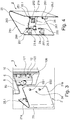
- FIGS. 3, 4 . 5A to 5C . 6A to 6B . 7 . 7A to 7B . 8 and 8C illustrate an alternative development of a panel VK according to the variant of Figures 1A and 1B in which in particular an alternatively removablestalteteter, automatically acting locking mechanism VM is provided.
- the closing element 2 is also formed here with a V-shaped cross section and can be attached to a rear side 10 of the receiving body 1 along the mounting direction E and thus in the axial direction with respect to the central axis M.
- the end element 2 is in this case of only one of the two side surfaces 21 a, 21 b from the receiving body 1 finally fixed and, if necessary, disassembled.
- bores for attachment points BS1 and BS2 are provided only on the one side surface 21b through which fastening elements BE (cf. FIG. 6B ), such as screws or bolts can be inserted when the closing element 2 is in a proper end position on the receiving body 1.
- a locking mechanism VM in this variant on the one hand a locking element in the form of a locking hook 61 the receiving body 1 and on the other hand, a plug pin 261 on the end element 2.
- the plug-in pin 261 of the end element 2 is part of a second locking assembly 26 which is provided on the end element 2.
- the second locking assembly 26 is completely housed within one of the two opposite side surfaces 21 a and 21 b and the back 10 of the receiving body 1 enclosed interior I when the end member 2 is attached to the receiving body 1.
- Part of the second locking assembly 26 is, inter alia, a support plate 260, via which the two side surfaces 21 a and 21 b are rigidly interconnected.
- a support plate 260 of the plug pin 261 is fixed and is from the support plate 260 in the mounting direction E from.
- a spring element in the form of a compression spring 262 is also mounted on the plug-in pin 261.
- a cooperating with the second locking assembly 26 of the closing element 2 first locking assembly 6 is on the in the flow direction SR and thus opposite to the attachment direction E projecting projection 100 of the receiving body 1 is provided.
- Part of this first locking assembly 6 is the adjustably mounted locking hook 61.
- This locking hook 61 is mounted on a support 60 of the first locking assembly 6.
- the carrier 60 forms an insertion opening 600 for the plug-in pin 261.
- the closing element 2 along the mounting direction E of the back 10 of the receiving body 1 is approximated and plugged into the projection 100. If the terminating element 2 has reached an intended end position, the push-in pin 261 with a conically tapered end passes through the access opening 100 on the carrier 60 of the first locking assembly 6.
- the diameter of the insertion opening 600 is dimensioned such that the compression spring 262 does not pass through the insertion opening 600 can be performed and is therefore supported on the carrier 60. The compression spring 262 is thus compressed and thereby tensioned until the plug pin 261 is guided with its end maximum through the insertion opening 600.
- the plug-in pin 261 is in this case inserted to the maximum when a circumferential groove lying in front of the conically tapering end of the plug-in pin 261 projects out of the plug-in opening 600 in the attachment direction E, so that the latching hook 61 can automatically act on it in a form-fitting manner.
- the locking hook 61 is biased in this case spring-loaded in a locking position in which the locking hook 61 engages positively in the groove of the plug pin 261. Upon insertion of the spigot 261 to the carrier 60 of the locking hook 61 is thus initially displaced against a spring force on the conical end of the spigot 61 until an engagement in the groove is possible.
- the locking hook 61 is rotatably mounted on the support 60 about a pivot axis parallel to the attachment direction E.
- the locking hook 61 for example, be mounted transversely to the mounting direction E slidably on the carrier 60 to engage in the manner of a locking pin in the groove of the spigot 261.
- a plurality of guide means 12 are formed on the rear side 10 laterally next to the projection 100 with opposite, respectively curved guide elements 121 and 122 on the receiving body 1. Between these guide elements 121, 122 are provided on the inner sides of the side surfaces 21 a and 21 b of the end element 2 provided mounting blocks in the form of Befestriensdomen 25.1 to 25.4. Here are two Befestriensdome 25.1, 25.2; 25.3, 25.4 provided on an inner side of a respective side surface 21 a or 21 b.
- the individual attachment domes 25.1 to 25.4 are each formed by a welded-on screw plate.
- Each attachment dome 25.1 to 25.4 is received at a proper attachment of the end member 2 to a guide element 12 of the receiving body 1 and can be held between the respective pair of vanes 121 and 122 form-fitting and optionally also non-positively.
- a pair of guide elements 121, 122 of a guide means 12 is designed as a pair of latching hooks prestressed on one another, so that a fastening dome 25.1 to 25.4 can be clipped thereto.
- an additional locking of the removable closing element 2 can be provided on the receiving body 1 via clipped Befest Trentsdome 25.1 to 25.4.
- the guide elements 121, 122 of the guide means 12 serve to predetermine the intended end position with respect to a (second) axis extending radially to the center axis M via the fastening domes 25.1 to 25.4 guided along this during assembly of the end element 2.
- This second (virtual) axis runs eg in the FIGS. 5A to 5C each vertically.
- the terminating element 2 is consequently given a designated radial position with respect to the receiving body 1 and also a spacer 5 explained in more detail below.
- the guide means 12 it is ensured via the guide means 12 that the side surfaces 21 a, 21 b of the end element 2 does not protrude radially outwards via a groove 50 of the spacer 5.
- the guide means 12 thus also prevent bending of the side surfaces 21 a, 21 b in the attachment to the receiving body. 1
- An attachment pair 25.3, 25.4 of a side surface 21 b is provided with through holes 250 for each one fastener in the form of a bolt BE.
- the respective passage opening 250 is located inside the interior I of a through hole defining an attachment point BS1 or BS2 on the outside of the side surface 21 b opposite.
- the respective bolt BE can be attached from the outside to the (additional) fixing of the terminating element 2 to the receiving body 1 when the terminating element 2 is plugged in and screwed onto the projection 100 of the receiving body 1.
- two Befest Trentsdome 25.1, 25.2 or 25.3, 25.4 per side are provided in the illustrated variant, this is of course not mandatory. For example, one attachment dome per side may be sufficient.
- an end position of the end element 2 with respect to the receiving body 1 is predetermined via the stop elements 251 of the end element 2, in which the side surfaces 21a and 21b are flush or almost flush with the lateral surface 10 of the receiving body 1 and then the fixation of the end element. 2 takes place on the receiving body 1. Also, over the stop lugs 251 too far displacement of the side surfaces 21a, 21b along the attachment direction E and any associated therewith, undesirable plastic deformation of the side surfaces 21 a, 21 b prevented.
- attachment points BS1 and BS2 for the additional fixation of the closure element 2 on the receiving body 1 only on one of the side surfaces 21 a, 21 b may be provided to specify an assembly and disassembly of the closure element 2 via exactly one page.
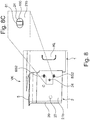
- an actuating opening 24 is also provided, which in the FIGS. 8 and 8C is illustrated in more detail.
- An actuating arm or lever of the locking hook 61 in the interior I is accessible via this actuating opening 24.
- the removable closing element 2 forming a rear edge of the lining VK collides with a component which is arranged on a radially outer bypass channel wall is the panel VK according to the embodiment of the FIGS. 3 to 8C additionally equipped with a spacer 5.
- the spacer 5 extends web-like on the back 10 of the receiving body 1 along the attachment direction E and thus substantially parallel to the center axis M of the turbofan engine T.
- the spacer 5 stands on the projection 100 of the receiving body 1 addition to the back 10 at the Receiving body 1 and can independently of a contact of the end member 2 with the projection 100 define a physical guide for the closing element 2 both when attaching to the receiving body 1 and when removing from the receiving body 1.
- the end element 2 is located with an upper side on the spacer 5.
- the Endologicalnabites 20 of the end element. 2 also flush with spacers 5 complete.
- the side surfaces 21a and 21b terminating element 2 can be flush or nearly flush with an outer circumferential surface of the spacer 5.
- an upper edge of the respective side surface 21a, 21b rests against a circumferential groove 50 of the spacer 5 in a condition connected to the intended condition.
- the spacer 5 is a minimum distance of the end element 2 with respect to the (in the FIG. 5A shown in broken lines) outer Bypasskanalwandung in the region of the receiving body 1, in particular when attaching the end member 2 to the receiving body 1 as well as the removal thereof.
- the risk is minimized that during assembly or disassembly of the end element 2 of this collides with an extension of the spacer 5 arranged on the outer Bypasskanalwandung component, for example, provided here a surface fan.
- a corresponding spacer may be provided for an inner bypass duct wall.
- the spacer 5 extends the aerodynamic rounding of the end bar portion 20 between the spacer 2 and the outer Bypasskanalwandung.
- the spacer 5 is presently designed as a separate component which is fixed to the receiving body 1 and / or on the outer Bypasskanalwandung, for example by means of at least one bolt.
- the spacer 5 may be formed of a different material than the receiving body 1 and / or the spacer element 2 of the panel VK.
- the spacer 5 is made of a composite material.
- the spacer 5 is formed by the receiving body 1, that is integrally formed thereon.
- the second locking assembly 26 is shown in a perspective single view and thus enlarged scale.
- a sleeve-shaped element for the mounting hole 24 On a front side of the carrier plate 260 with the plug pin 261 and the compression spring 262 is on a laterally projecting extension a sleeve-shaped element for the mounting hole 24.
- a V-shaped support structure 263 At a rear side of the support plate 260 is centrally fixed a V-shaped support structure 263, for example, welded.
- This support structure 263 serves to support the support plate 260 on the side surfaces 21 a and 21 b of the end element 2.
- the support structure 263 is fixed for this purpose at its two projecting from the support plate 260 ends about bent portions on the inside of a respective side surface 21 a or 21 b , for example, also by welding.
- FIG. 10 shows the panel VK of the basis of the FIGS. 3 to 9 explained embodiment variant with receiving body 1, end element 2 and spacer 5 in the assembled state in a perspective view and with a view of that side of the panel VK, on the one hand the attachment points BS1 and BS2 and the actuating opening 24 are provided.
Abstract
Die vorliegende Erfindung betrifft ein Turbofan-Triebwerk, mit - einem Kerntriebwerk (K) und mindestens einem Fan (F), mittels dem Fluid sowohl zu einem Primärstromkanal für das Kerntriebwerk (K) als auch zu einem Sekundärstromkanal (BD) des Turbofan-Triebwerks (T) geleitet wird, wobei der Sekundärstromkanal (BD) für einen äußeren, an dem Kerntriebwerk (K) vorbeigeführten Fluidstrom vorgesehen ist, und - mindestens einer in dem Sekundärstromkanal (BD) angeordneten und von dem Fluidstrom im Betrieb des Turbofan-Triebwerks (T) umströmten Verkleidung (VK), die mindestens eine radial durch den Sekundärstromkanal (BD) geführte Komponente (L1, L2) des Turbofan-Triebwerks (T) zumindest teilweise verkleidet und die ein Abschlusselement (2) mit einem dem Fluidstrom zugewandten Nasenleistenabschnitt und/oder einem in Strömungsrichtung (SR) des Fluidstroms liegenden Endleistenabschnitt (20) aufweist, Erfindungsgemäß ist das Abschlusselement (2) mit dem Nasenleisten- und/oder Endleistenabschnitt (20) ein separates Bauteil, das mit einem im Sekundärstromkanal (BD) angeordneten und die mindestens eine Komponente (L1, L2) aufnehmenden Aufnahmekörper (1) der Verkleidung (VK) lösbar verbunden ist, wobei das Abschlusselement (2) an den Aufnahmekörper (1) steckbar ist und das an den Aufnahmekörper (1) gesteckte Abschlusselement (2) über einen selbsttätig wirkenden Verriegelungsmechanismus (VM) an dem Aufnahmekörper (1) werkzeuglos gesichert istThe present invention relates to a turbofan engine, with - A core engine (K) and at least one fan (F), by means of which fluid is passed both to a primary flow channel for the core engine (K) and to a secondary flow channel (BD) of the turbofan engine (T), wherein the secondary flow channel (BD ) is provided for an outer, past the core engine (K) fluid flow, and - At least one arranged in the secondary flow channel (BD) and by the fluid flow during operation of the turbofan engine (T) flow around the panel (VK), the at least one radially through the secondary flow channel (BD) guided component (L1, L2) of the turbofan engine (T) at least partially clad and having a closure element (2) with a fluid stream facing the nose strip portion and / or lying in the flow direction (SR) of the fluid stream Endleistenabschnitt (20), According to the invention, the closing element (2) with the nose strip and / or Endleistenabschnitt (20) a separate component which is detachably connected to a in the secondary flow channel (BD) and the at least one component (L1, L2) receiving receiving body (1) of the lining (VK), wherein the closing element (2) to the Receiving body (1) can be plugged and attached to the receiving body (1) end element (2) via an automatically acting Verriegelungsmechanismu s (VM) on the receiving body (1) is secured without tools
Description
Die Erfindung betrifft ein Turbofan-Triebwerk gemäß dem Oberbegriff des Anspruchs 1.The invention relates to a turbofan engine according to the preamble of
Turbofan-Triebwerke werden auch als Mantelstrom- oder Nebenstromtriebwerke bezeichnet. Sie zeichnen sich dadurch aus, dass der Fan (auch als Bläser bezeichnet) von einer hinter der Brennkammer des Turbofan-Triebwerks angeordneten Turbine angetrieben wird, wobei ein großer Anteil der von dem Triebwerk angesaugten Luftmasse an einem die Brennkammer aufweisenden Kerntriebwerk vorbei beschleunigt wird. Das Turbofan-Triebwerk bildet dabei einen Primärstromkanal durch das Kerntriebwerk sowie einen Sekundärstromkanal für einen äußeren Fluidstrom, der an dem Kerntriebwerk vorbei geführt wird.Turbofan engines are also referred to as bypass or bypass engines. They are distinguished by the fact that the fan (also referred to as fan) is driven by a turbine arranged behind the combustion chamber of the turbofan engine, wherein a large proportion of the air mass drawn in by the engine is accelerated past a core engine having the combustion chamber. The turbofan engine forms a primary flow channel through the core engine and a secondary flow channel for an external fluid flow, which is guided past the core engine.
Innerhalb des Turbofan-Triebwerks und insbesondere durch den Sekundärstromkanal sind unterschiedliche Komponenten, wie Leitungen, Streben oder verstellbare Koppelelemente, verlegt. Diese müssen teilweise durch den Sekundärstromkanal radial nach außen geführt werden. In entsprechenden Leitungen ist beispielsweise Luft oder Öl geführt oder es handelt sich um Strom- oder Signalleitungen. Verstellbare und radial durch den Sekundärstromkanal geführte Koppelelemente dienen beispielsweise der mechanischen Kopplung und dem Antrieb von Systemen, die zur besseren Kühlung radial außen bezüglich des Kerntriebwerks in einem Triebwerksgehäuse untergebracht sind, wie z.B. eines Zusatzgetriebes, einer Kraftstoffpumpe, einer Ölpumpe oder eines Generators. Um dabei die jeweiligen Komponenten vor äußeren Einflüssen geschützt und aerodynamisch weniger störend durch den Sekundärstromkanal führen zu können, ist üblicherweise eine Verkleidung (englisch "splitter fairing") vorgesehen, durch die die jeweiligen Komponenten innerhalb des Sekundärstromkanals verkleidet sind, so dass ein in dem Strömungskanal strömendes Fluid aerodynamisch möglichst günstig an den Komponenten vorbeigeführt wird. Diese Verkleidung ist in dem Sekundärstromkanal angeordnet und erstreckt sich bezogen auf eine Mittelachse des Turbofan-Triebwerks insbesondere in radialer Richtung in dem Sekundärstromkanal.Within the turbofan engine and in particular through the secondary flow channel are different components, such as cables, struts or adjustable coupling elements laid. These must be partially passed through the secondary flow channel radially outward. In appropriate lines, for example, air or oil out or it is power or signal lines. Adjustable and radially guided by the secondary flow channel coupling elements serve for example the mechanical coupling and the drive of systems that are housed for better cooling radially outward with respect to the core engine in an engine housing, such as an additional gear, a fuel pump, an oil pump or a Generator. In order to protect the respective components from external influences and aerodynamically less disturbing to lead through the secondary flow channel, usually a fairing (English "splitter fairing") is provided, through which the respective components are covered within the secondary flow channel, so that one in the flow channel flowing fluid is aerodynamically as low as possible passed to the components. This panel is arranged in the secondary flow channel and extends with respect to a central axis of the turbofan engine, in particular in the radial direction in the secondary flow channel.
Die Verkleidung weist für die gezielte Führung des Fluidstroms um die Verkleidung herum ein Abschlusselement auf, das einen dem Fluidstrom zugewandten Nasenleistenabschnitt (englisch "leading edge section") und/oder einen in Strömungsrichtung des Fluidstroms liegenden Endleistenabschnitt (englisch "trailing edge section") auf. In der Praxis handelt es sich bei derartigen Verkleidungen um strukturell vergleichsweise einfach gestaltete Bauteile, die üblicherweise an einer radial innen liegenden und/oder radial außen liegenden Wandung des Sekundärstromkanals fixiert sind. So zeigt beispielsweise auch die
Auch aus der
Die in der
Der Erfindung liegt daher die Aufgabe zugrunde, ein in dieser Hinsicht verbessertes Turbofan-Triebwerk mit einer in einem Sekundärstromkanal angeordneten Verkleidung bereitzustellen.The invention is therefore based on the object to provide an improved in this respect turbofan engine with a arranged in a secondary flow channel panel.
Diese Aufgabe wird mit einem Turbofan-Triebwerk des Anspruchs 1 gelöst.This object is achieved with a turbofan engine of
Hiernach ist erfindungsgemäß vorgesehen, dass die in dem Sekundärstromkanal (auch Bypasskanal genannt) angeordnete und von dem Fluidstrom im Betrieb des Turbofan-Triebwerks umströmte Verkleidung wenigstens zweiteilig ausgeführt ist und neben einem die mindestens eine in dem Sekundärstromkanal radial verlaufende Komponente aufnehmenden Aufnahmekörper ein als separates Bauteil ausgeführtes Abschlusselement mit einem Nasenleisten- und/oder Endleistenabschnitt aufweist. Der Aufnahmekörper, der insbesondere für die Verkleidung Fluid führender Leitungen z.B. als hohlzylindrischen Druckkörper ausgeführt sein kann, kann somit aus einem anderen Material hergestellt sein als das den Nasenleisten- und/oder Endleistenabschnitt ausbildende Abschlusselement, das vornehmlich mit Blick auf eine möglichst aerodynamisch günstige Geometrie ausgestaltet. So kann das separate Abschlusselement aus einem weniger steifen und leichteren Material hergestellt sein als der Aufnahmekörper, der in einem Versagensfall, bei dem eine durch die Verkleidung zumindest teilweise verkleidete Komponente versagt, vergleichsweise hohe Kräfte absorbieren können soll. Durch die lösbare Befestigung des Abschlusselements an dem Aufnahmekörper ist zudem erreicht, dass sowohl die Montage als auch die Demontage der Verkleidung vereinfacht werden kann und die im Bereich der Verkleidung oder innerhalb des Aufnahmekörpers geführten Komponenten erheblich leichter zugänglich sind.Thereafter, the invention provides that in the secondary flow channel (also called bypass channel) arranged and flowed around by the fluid flow during operation of the turbofan engine cowling is designed at least two parts and next to a at least one radially extending in the secondary flow component receiving body as a separate component having executed closure element with a nose strip and / or Endleistenabschnitt. The receiving body, in particular for the lining fluid leading lines, e.g. can be designed as a hollow cylindrical pressure body can thus be made of a different material than the Nasenleisten- and / or Endleistenabschnitt forming end element, which designed primarily with a view to a possible aerodynamically favorable geometry. Thus, the separate closing element may be made of a less rigid and lighter material than the receiving body, which should be able to absorb relatively high forces in a failure case in which a component at least partially disguised by the lining component to absorb. Due to the releasable attachment of the closure element to the receiving body is also achieved that both the assembly and disassembly of the panel can be simplified and the run in the panel or within the receiving body components are much more accessible.
Beispielsweise weist das Abschlusselement mit Blick auf eine aerodynamisch günstige Geometrie einen V-förmigen oder dreiecksförmigen Querschnitt auf, bei dem sich von einer Nasenleiste oder Endleiste zwei mit dem Aufnahmekörper verbundene Seitenflächen schenkelartig weg erstrecken. Über ein derartiges Abschlusselement wird somit eine Fluidströmung ausgehend von der Nasenleiste an dem Abschlusselement und der Verkleidung entlang geführt. Über einen sich entsprechend verjüngenden Endleistenabschnitt des Abschlusselements wird analog die durch die Verkleidung geteilte Fluidströmung am Ende der Verkleidung wieder zusammengeführt.For example, the closing element with a view to an aerodynamically favorable geometry on a V-shaped or triangular cross-section, in which extend from a nose strip or end bar two side surfaces connected to the receiving body leg-like away. By means of such a terminating element, a fluid flow is thus guided along the end element and the lining starting from the leading edge. About a correspondingly rejuvenating End strip portion of the end element is analogously merged through the panel fluid flow merged at the end of the panel again.
Der Fan, das Kerntriebwerk und ein Auslass des Turbofan-Triebwerks sind typischerweise entlang einer Mittelachse des Triebwerks hintereinander angeordnet. In einer Ausführungsvariante ist nun das Abschlusselement entlang einer axialen Richtung bezüglich dieser Mittelachse an dem Aufnahmekörper bestimmungsgemäß anbringbar. Das Abschlusselement ist folglich nicht von oben oder unten an dem Aufnahmekörper anbringbar, sondern ist bestimmungsgemäß entlang an einer Anbringungsrichtung an dem Aufnahmekörper innerhalb des Sekundärstromkanals anbringbar, die im Wesentlichen parallel zur Mittelachse des Turbofan-Triebwerks verläuft.The fan, the core engine and an outlet of the turbofan engine are typically arranged in series along a central axis of the engine. In one embodiment variant, the closing element can now be attached to the receiving body in an intended manner along an axial direction with respect to this central axis. Consequently, the end element can not be attached to the receiving body from above or below, but can be attached along a direction of attachment to the receiving body within the secondary flow channel, which runs essentially parallel to the center axis of the turbofan engine.
Erfindungsgemäß ist das Abschlusselement ferner an den Aufnahmekörper steckbar. Um dabei die Montage und Demontage weiter zu vereinfachen ist ein an den Aufnahmekörper gestecktes Abschlusselement über einen selbsttätig wirkenden Verriegelungsmechanismus an dem Aufnahmekörper werkzeuglos gesichert. Das Abschlusselement wird folglich zunächst einfach an den Aufnahmekörper entlang einer Anbringungsrichtung gesteckt und ist hieran dann automatisch über den selbsttätig wirkenden Verriegelungsmechanismus gehalten, ohne dass hierfür ein Werkzeug genutzt werden und beispielsweise zusätzliche Befestigungselemente, wie Schrauben, Bolzen oder Niete, angebracht werden müssten. Das lösbar an dem Aufnahmekörper anzubringende Abschlusselement mit dem Nasenleisten- und/oder Endleistenabschnitt (mithin also gegebenenfalls einer dem Fluidstrom zugewandten Vorderkante oder einer in Strömungsrichtung des Fluidstroms liegenden Hinterkante) kann somit an dem Aufnahmekörper durch einfaches Anstecken in einer vorgegebenen Endlage arretiert werden.According to the invention, the closing element can furthermore be plugged into the receiving body. To further simplify the assembly and disassembly while a plugged into the receiving body end element is secured by a self-acting locking mechanism on the receiving body without tools. The closing element is therefore initially simply plugged into the receiving body along a mounting direction and is then automatically held on the automatically acting locking mechanism, without the use of a tool and, for example, additional fasteners, such as screws, bolts or rivets, would have to be attached. The releasably attached to the receiving body terminating element with the Nasenleisten- and / or Endleistenabschnitt (thus possibly a fluid stream facing the leading edge or lying in the flow direction of the fluid flow trailing edge) can thus be locked to the receiving body by simply plugging in a predetermined end position.
In dieser Endlage können zusätzliche Befestigungselemente zur endgültigen Fixierung des Abschlusselements an dem Aufnahmekörper angebracht werden. Es ist jedoch auch ohne derartige Befestigungselemente über den selbsttätig wirkenden Verriegelungsmechanismus erreicht, dass das Abschlusselement an dem Aufnahmekörper gesichert ist. Werden beispielsweise bei der Montage der Verkleidung Befestigungselemente vergessen, ist das Abschlusselement über den Verriegelungsmechanismus dennoch an dem Aufnahmekörper gehalten und kann sich nicht von diesem ablösen. Ferner verbleibt das Abschlusselement auch nach Entfernen von gegebenenfalls zusätzlich vorgesehenen Befestigungselementen zur Fixierung des Abschlusselements an dem Aufnahmekörper in einer vorgegebenen Position, bis der Verriegelungsmechanismus betätigt und eine entsprechende Verriegelung gelöst wird.In this end position additional fasteners for final fixation of the closure element can be attached to the receiving body. However, it is also achieved without such fasteners on the self-acting locking mechanism, that the closing element is secured to the receiving body. For example, if fasteners are forgotten during assembly of the panel, the closing element is still held on the receiving body via the locking mechanism and can not detach from this. Furthermore, the closing element remains even after removal of possibly additionally provided fastening elements for fixing the Termination element on the receiving body in a predetermined position until the locking mechanism is actuated and a corresponding lock is released.
Der Verriegelungsmechanismus kann beispielsweise mindestens ein Verriegelungselement an dem Aufnahmekörper umfassen, welches selbsttätig mit einem Element und/oder Abschnitt des Abschlusselements verriegelt, wenn das Abschlusselement bestimmungsgemäß an den Aufnahmekörper gesteckt ist. Beispielsweise treten hierbei das mindestens eine Verriegelungselement und das Element und/oder der Abschnitt des Abschlusselements selbsttätig miteinander in verriegelnden, formschlüssigen Kontakt, wenn das Abschlusselement bestimmungsgemäß an den Aufnahmekörper gesteckt wird.The locking mechanism may comprise, for example, at least one locking element on the receiving body, which automatically locks with an element and / or portion of the closing element when the closing element is intended to be plugged into the receiving body. For example, in this case, the at least one locking element and the element and / or the section of the closure element automatically engage in interlocking, positive-locking contact when the closure element is intended to be inserted against the receiving body.
In einer Ausführungsvariante ist hierfür vorgesehen, dass das Verriegelungselement des Aufnahmekörpers und/oder das Element des Abschlusselements elastisch ausgebildet und/oder federnd gelagert ist. Beim Aufstecken des Abschlusselements kann sich somit das Verriegelungselement des Aufnahmekörpers und/oder das Element des Abschlusselements zunächst entgegen einer Rückstellkraft elastisch verlagern. Nimmt das Abschlusselement eine bestimmungsgemäße Endlage an dem Aufnahmekörper ein, wird das jeweilige Element unter Wirkung der Rückstellkraft in eine Verriegelungsposition verstellt.In one embodiment, it is provided for this purpose that the locking element of the receiving body and / or the element of the end element is designed to be elastic and / or resiliently mounted. When attaching the end element thus the locking element of the receiving body and / or the element of the end element can initially displace elastically against a restoring force. If the terminating element assumes an intended end position on the receiving body, the respective element is adjusted under the action of the restoring force into a locking position.
Nach einem Ausführungsbeispiel ist vorgesehen, dass das Verriegelungselement eine elastische Federplatte umfasst, die in einem verriegelten Zustand des Verriegelungsmechanismus mit mindestens einem Verriegelungsabschnitt formschlüssig in einen Sicherungsschlitz eingreift. Der mindestens eine Verriegelungsabschnitt der elastischen Federplatte kann hierbei durch den formschlüssigen Eingriff in den Sicherungsschlitz das Abschlusselement an dem Aufnahmekörper arretieren. Hierfür ist beispielsweise vorgesehen, dass durch den in den Sicherungsschlitz eingreifenden Verriegelungsabschnitt ein den Sicherungsschlitz berandender Abschnitt des Abschlusselements und/oder eines hiermit verbundenen Teils hintergriffen ist. Dabei wird der Verriegelungsabschnitt unter der Federwirkung der elastisch ausgestalteten Federplatte innerhalb des Sicherungsschlitzes selbsttätig in eine Verriegelungsposition gedrückt oder gezogen, in der der Verriegelungsabschnitt den Sicherungsschlitz berandenden Abschnitt hintergreift, wenn das Abschlusselement sein Endlage bezüglich des Aufnahmekörpers einnimmt.According to one embodiment, it is provided that the locking element comprises an elastic spring plate, which engages in a locked state of the locking mechanism with at least one locking portion form-fitting manner in a securing slot. The at least one locking portion of the elastic spring plate can in this case lock the closing element on the receiving body by the positive engagement in the securing slot. For this purpose, it is provided, for example, that a section of the closure element bordering the securing slot and / or a part connected thereto is engaged behind by the locking section engaging in the securing slot. In this case, the locking portion is automatically pressed or pulled under the spring action of the elastically designed spring plate within the securing slot in a locking position in which the locking portion engages behind the securing slot portion when the closing element occupies its end position with respect to the receiving body.
In diesem Zusammenhang kann insbesondere vorgesehen sein, dass der Sicherungsschlitz L-förmig oder Hakenförmig ausgebildet ist. Derart kann ein während des Ansteckens des Abschlusselements an den Aufnahmekörper in dem L-förmigen oder hakenförmigen Sicherungsschlitz geführter Verriegelungsabschnitt bei Erreichen der Endlage des Abschlusselements selbsttätig innerhalb des Sicherungsschlitzes in einen Bereich verlagert werden, in dem ein Abschnitt an dem Abschlusselement von dem Verriegelungselement hintergriffen und eine Arretierung des Abschlusselements an dem Aufnahmekörper bereitgestellt ist.In this context, it may in particular be provided that the securing slot is L-shaped or hook-shaped. In this way, a locking section guided on the receiving body in the L-shaped or hook-shaped securing slot while the end element is being abutted can, upon reaching the end position of the closing element, be displaced automatically within the securing slot into a region in which a section engages behind the locking element and engages behind the locking element Arresting of the closure element is provided on the receiving body.
Hierbei kann auch vorgesehen sein, dass die Federplatte zwei Verriegelungsabschnitte aufweist, die räumlich zueinander beabstandet sind. In einer hierauf basierenden Weiterbildung greift beispielsweise ein erster Verriegelungsabschnitt der Federplatte in einen ersten Sicherungsschlitz eines Halteteils ein, das an einer ersten Seitenfläche des Abschlusselements vorgesehen ist. Ein zweiter Verriegelungsabschnitt der Federplatte greift demgegenüber in einen zweiten Sicherungsschlitz an einer der ersten Seitenfläche gegenüberliegenden zweiten Seitenfläche des Abschlusselementes ein. Derart ist über die einzelne Federplatte eine Arretierung des Abschlusselements an zwei sich gegenüberliegenden Seitenflächen mithilfe zweier jeweils in einen Sicherungsschlitz eingreifende Verriegelungsabschnitte erreicht.It can also be provided that the spring plate has two locking portions which are spatially spaced from each other. In a refinement based thereon, for example, a first locking section of the spring plate engages in a first securing slot of a holding part, which is provided on a first side face of the closing element. In contrast, a second locking section of the spring plate engages in a second securing slot on a second side face of the closing element opposite the first side face. In this way, a locking of the closing element on two opposite side surfaces is achieved by means of two engaging in a securing slot locking sections on the individual spring plate.
Das Halteteil mit dem ersten Sicherungsschlitz kann hierbei an einer im bestimmungsgemäß verbundenen Zustand von Aufnahmekörper und Abschlusselement nicht zugänglichen Innenseite der ersten Seitenfläche vorgesehen sein, während der zweite Sicherungsschlitz an einer Außenseite der zweite Seitenfläche zugänglich ist. Hierüber ist erreicht, dass die Federplatte nur von einer der Seitenflächen aus über ein Verlagern des zweiten Verriegelungsabschnitts an dem zweiten Sicherungsschlitz verstellt werden kann. Indem die beiden Verriegelungsabschnitte an der Federplatte starr miteinander verbunden sind, wird der eine, erste Verriegelungsabschnitt automatisch mitverstellt, wenn der andere zugängliche, zweite Verriegelungsabschnitt an der zweiten Seitenfläche verstellt wird, beispielsweise um eine Verriegelung über den Verriegelungsmechanismus zu lösen.The holding part with the first securing slot may in this case be provided on an inside of the first side face, which is not accessible in the intended condition of the receiving body and closing element, while the second securing slot is accessible on an outer side of the second side face. This ensures that the spring plate can be adjusted only from one of the side surfaces via a displacement of the second locking portion on the second securing slot. By the two locking portions are rigidly connected to the spring plate, the one, first locking portion is automatically mitverstellt when the other accessible, second locking portion is adjusted on the second side surface, for example, to release a lock on the locking mechanism.
In einer anderen Ausführungsvariante ist vorgesehen, dass das Verriegelungselement des Aufnahmekörpers einen verstellbar gelagerten Verriegelungshaken umfasst. Dieser Verriegelungshaken ist in einem bestimmungsgemäß verbundenen Zustand von Aufnahmekörper und Abschlusselement mit einem Steckzapfen des Abschlusselements formschlüssig verriegelt. Hierbei wird folglich das Abschlusselement mit seinem Steckzapfen an den Aufnahmekörper gesteckt, wobei in einer bestimmungsgemäßen Endlage des Abschlusselements an dem Aufnahmekörper der vorzugsweise federnd in eine Verriegelungsposition vorgespannte Verriegelungshaken automatisch an oder in den Steckzapfen einschnappt, um das Abschlusselement an dem Aufnahmekörper zu halten. In einer Ausführungsvariante ist an dem Steckzapfen ein Federelement, beispielsweise in Form einer Druckfeder, gelagert. Über ein solches Federelement wird z.B. eine ausreichend stabile, formschlüssige Verbindung zwischen Abschlusselement und Aufnahmekörper unterstützt. Hierüber kann beispielsweise der in eine Durchgangsöffnung eingesteckte Steckzapfen unter Wirkung der Federkraft in Längsrichtung des Einsteckzapfens gegen einen Verriegelungshaken des Aufnahmekörper gedrückt oder gezogen werden, der in eine umlaufende Rille des Steckzapfens greift, um den Eingriff des Verriegelungshakens in die umlaufende Rille des Steckzapfens zu sichern. Zur Aufbringung der hierfür notwendigen Federkraft stützt sich eine Druckfeder in einer Variante einerseits an einem Rand des Steckzapfens oder einer den Steckzapfen der tragenden Trägerplatte des Abschlusselements und andererseits an einem Träger, an dem der Verriegelungshaken verstellbar gelagert ist, ab.In another embodiment, it is provided that the locking element of the receiving body comprises an adjustably mounted locking hook. This locking hook is positively locked in a properly connected state of receiving body and end element with a plug pin of the end element. In this case, therefore, the final element with his Plug-in pin inserted into the receiving body, wherein in an intended end position of the closing element on the receiving body of the spring-biased preferably in a locking position locking hook automatically snaps on or in the plug in order to hold the closing element on the receiving body. In one embodiment, a spring element, for example in the form of a compression spring, is mounted on the plug-in pin. About such a spring element, for example, a sufficiently stable, positive connection between the end member and receiving body is supported. By way of example, the plug-in pin inserted into a passage opening can be pressed or pulled against a locking hook of the receiving body in the longitudinal direction of the plug-in pin, which engages in a circumferential groove of the plug-in pin in order to secure the engagement of the locking hook in the circumferential groove of the plug-in pin. To apply the necessary spring force, a compression spring is supported in a variant on the one hand on an edge of the spigot or the spigot of the supporting support plate of the closing element and on the other hand on a support on which the locking hook is adjustably mounted from.
Der Verriegelungsmechanismus kann manuell betätigbar sein, um eine Verriegelung zur Sicherung des Abschlusselements an dem Aufnahmekörper zu lösen. Erst nach manueller Betätigung des Verriegelungsmechanismus kann folglich das Abschlusselement von dem Aufnahmekörper - gegebenenfalls nach Entfernen zusätzlicher Befestigungselemente für die Fixierung des Abschlusselements an dem Aufnahmekörper - getrennt werden. Z.B. wird hierfür ein Verriegelungselement des Verriegelungsmechanismus oder ein mit dem Verriegelungselement zusammenwirkendes, entsprechend ausgestaltetes Betätigungselement manuell verstellt wird. Das Abschlusselement ist hierbei folglich über einen selbstsichernden Verriegelungsmechanismus an dem Aufnahmekörper gehalten, der manuell betätigt werden kann, um das Abschlusselement von dem Aufnahmekörper entfernen zu können.The locking mechanism may be manually operable to release a lock for securing the end member to the receiving body. Only after manual actuation of the locking mechanism, consequently, the closure element of the receiving body - optionally after removing additional fasteners for the fixation of the closure element to the receiving body - are separated. For example, For this purpose, a locking element of the locking mechanism or a cooperating with the locking element, appropriately ausgestaltetes actuator is manually adjusted. The closure element is thus held by a self-locking locking mechanism on the receiving body, which can be manually operated to remove the closing element of the receiving body can.
In diesem Zusammenhang kann auch vorgesehen sein, dass ein Verriegelungselement des Verriegelungsmechanismus in einem von dem mit dem Aufnahmekörper verbundenen Abschlusselement definierten Innenraum aufgenommen ist. Dieser Innenraum wird von mindestens einer Innenseite einer Seitenfläche des Verriegelungselements berandet, wobei der Verriegelungsmechanismus von einer Außenseite dieser Seitenfläche aus manuell betätigbar ist, um eine Verriegelung zur Sicherung des Abschlusselements an dem Aufnahmekörper zu lösen. Der Verriegelungsmechanismus mit dem innen liegenden Verriegelungselement kann somit problemlos von außen betätigt und gelöst werden.In this context, it can also be provided that a locking element of the locking mechanism is accommodated in an inner space defined by the closing element connected to the receiving body. This inner space is bounded by at least one inner side of a side surface of the locking element, wherein the locking mechanism is manually operable from an outer side of this side surface to release a lock for securing the closure element to the receiving body. Of the Locking mechanism with the inner locking element can thus be easily operated and released from the outside.
Alternativ oder ergänzend kann vorgesehen sein, dass das Abschlusselement zwei voneinander abgewandte und über den Nasenleistenabschnitt oder über den Endleistenabschnitt des Abschlusselements miteinander verbundene Seitenflächen aufweist und der Verriegelungsmechanismus an nur genau einer der Seitenflächen betätigbar ist, um eine Verriegelung zu lösen. Hiernach ist folglich der Verriegelungsmechanismus nur von einer Seite des Abschlusselements aus zu betätigen. Derart ist nicht nur eine definierte Demontagereihenfolge leicht vorgebbar, sondern auch erreicht, dass ein Zugang zu dem Abschlusselement von nur einer Seite aus ausreichend ist, um das Abschlusselement von dem Aufnahmekörper der Verkleidung abnehmen zu können.Alternatively or additionally, it may be provided that the closure element has two side faces facing away from each other and connected to one another via the nose strip section or via the end strip section of the closure element, and the locking mechanism can be actuated on only exactly one of the side faces in order to release a lock. After that, consequently, the locking mechanism is to be actuated only from one side of the closing element. In this way, not only a defined dismantling sequence can be easily predefined, but also ensures that access to the closing element from only one side is sufficient to be able to remove the closing element from the receiving body of the lining.
In einer Ausführungsvariante weist die Verkleidung einen Abstandshalter auf, um zu vermeiden, dass das Abschlusselement bei der Montage oder Demontage der Verkleidung mit gegebenenfalls empfindlichen Komponenten des Turbofan-Triebwerks kollidiert. Beispielsweise sind im Bereich einer inneren oder äußeren Wandung des Sekundärstromkanals elektronische Komponenten oder (Flächen-) Kühler vorgesehen, die bei einem Entfernen des Abschlusselements von dem Aufnahmekörper leicht beschädigt werden können. Der Abstandshalter der Verkleidung ist hierfür an der innen liegenden oder außen liegenden Wandung des Sekundärstromkanals vorgesehen, sodass das Abschlusselement im bestimmungsgemäß mit dem Aufnahmekörper verbundenen Zustand durch den Abstandshalter von der jeweiligen Wanderung beabstandet ist und mit einer Ober- oder Unterseite an dem Abstandshalter anliegt. Der Abstandshalter erstreckt sich hierbei vorzugsweise längs einer Anbringungsrichtung, entlang der das Abschlusselement bestimmungsgemäß an den Aufnahmekörper anbringbar ist. Derart kann das Abschlusselement sowohl bei der Montage als auch Demontage an dem Abstandshalter entlang geführt werden.In one embodiment, the shroud comprises a spacer to prevent the terminating element from colliding with possibly turbofan turbofan components during assembly or disassembly of the shroud. For example, in the region of an inner or outer wall of the secondary flow channel, electronic components or (area) coolers are provided which can easily be damaged when the terminating element is removed from the receiving body. The spacer of the panel is provided for this purpose on the inner or outer wall of the secondary flow channel, so that the closing element is in the intended connected to the receiving body state by the spacer spaced from the respective migration and rests with a top or bottom of the spacer. In this case, the spacer preferably extends along an attachment direction along which the closure element can be attached as intended to the receiving body. In this way, the closing element can be guided along the spacer both during assembly and disassembly.
Der Abstandshalter gibt dabei durch seine quer zur Anbringungsrichtung gemessene Dicke einen von dem Abschlusselement einzuhaltenden Abstand zu der Wanderung des Sekundärstromkanals vor, an der der Abstandshalter vorgesehen ist. Hierüber ist dann das Risiko reduziert, dass das zu montierende oder abgenommene Abschlusselement mit einer Komponente des Turbofan-Triebwerks kollidiert, das in Verlängerung des Abstandshalters an der jeweiligen Kanalwandung angeordnet ist.By means of its thickness, which is measured transversely with respect to the direction of attachment, the spacer predetermines a distance to be maintained by the terminating element from the migration of the secondary flow duct on which the spacer is provided. This then reduces the risk that the end element to be mounted or removed collides with a component of the turbofan engine, which is arranged in extension of the spacer on the respective channel wall.
Der Abstandshalter kann beispielsweise stabförmig ausgebildet sein und/oder über wenigstens ein Befestigungselement, wie zum Beispiel einen Bolzen oder eine Schraube, an der jeweiligen Kanalwandung fixiert sein. Alternativ oder ergänzend ist der Abstandshalter integraler Bestandteil des Aufnahmekörpers oder hieran als separates Bauteil der dann wenigstens dreiteiligen Verkleidung fixiert.The spacer may for example be rod-shaped and / or be fixed to the respective channel wall via at least one fastening element, such as a bolt or a screw. Alternatively or additionally, the spacer is an integral part of the receiving body or fixed thereto as a separate component of the then at least three-piece panel.
In einer Ausführungsvariante ist an dem Aufnahmekörper der Verkleidung, an dem das Abschlusselement angebracht ist, ein in Richtung des Abschlusselements vorstehender Vorsprung vorgesehen. Dieser Vorsprung kann Führungsabschnitte für das Anbringen des Abschlusselements an dem Aufnahmekörper eine körperliche Führung für das Abschlusselement aufweisen, insbesondere ausbilden. Beispielsweise bilden die Führungsabschnitts hierfür jeweils eine geneigt zur Anbringungsrichtung des Abschlusselements verlaufende Schräge aus, über die eine automatische Zentrierung des Abschlusselements bezüglich des Vorsprung bei Anbringung des Abschlusselements erreicht ist.In one embodiment variant, a protrusion projecting in the direction of the end element is provided on the receiving body of the cladding, to which the closing element is attached. This projection can guide sections for the attachment of the closure element to the receiving body have a physical guide for the closing element, in particular train. For example, the guide portion for this purpose each form a slope inclined relative to the attachment direction of the end element, via which an automatic centering of the end element with respect to the projection when attaching the end element is achieved.
In einer Ausführungsvariante ist das Abschlusselement entlang einer Anbringungsrichtung an den Aufnahmekörper bestimmungsgemäß anbringbar und an dem Aufnahmekörper ist wenigstens ein Leitmittel vorgesehen ist, mittels dem dem Abschlusselement bei seiner Anbringung an den Aufnahmekörper bezüglich einer quer zur Anbringungsrichtung verlaufenden Achse und/oder bezüglich einer radial zu einer Mittelachse des Turbofan-Triebwerks verlaufenden Achse eine bestimmungsgemäße Endlage vorgegeben wird. Ein entsprechendes Leitmittel stellt somit sicher, dass das Abschlusselement in seiner Endlage in einer bestimmten radialen Position vorliegt, bevor das Abschlusselement an dem Aufnahmekörper fixiert wird.In one embodiment variant, the closing element can be attached as intended to the receiving body along an attachment direction and at least one guiding means is provided on the receiving body, by means of which the closing element when attached to the receiving body with respect to an axis extending transversely to the mounting direction and / or with respect to a radially to one Center axis of the turbofan engine axis extending a predetermined end position is specified. A corresponding guide means thus ensures that the closing element is present in its end position in a specific radial position before the closing element is fixed to the receiving body.
In einer Weiterbildung ist in Kombination mit den vorstehend genannten Führungsabschnitte vorgesehen, dass mittels der Führungsabschnitte des Aufnahmekörpers dem Abschlusselement bei seiner Anbringung an den Aufnahmekörper bezüglich einer quer zur Anbringungsrichtung verlaufenden ersten Achse eine bestimmungsgemäße Endlage vorgegeben wird und mittels des wenigstens einen Leitmittels des Aufnahmekörpers eine bestimmungsgemäße Endlage bezüglich einer zweiten Achse, die sowohl quer zur Anbringungsrichtung als auch quer zu der ersten Achse verläuft. Über die Führungsabschnitte kann somit bei der Anbringung des Abschlusselementes an den Aufnahmekörper eine Zentrierung zweier sich quer zur Anbringungsrichtung gegenüberliegender Seitenflächen des Abschlusselements erreicht werden, während über das wenigstens eine Leitmittel quer hierzu und in radialer Richtung einer Vorgabe der bestimmungsgemäßen Endlage und mithin eine radiale Positionierung des Abschlusselements erfolgt.In a development, it is provided in combination with the above-mentioned guide sections that by means of the guide portions of the receiving body the terminating element in its attachment to the receiving body with respect to a first axis extending transversely to the attachment direction a predetermined end position is predetermined and by means of at least one conductive agent of the receiving body End position with respect to a second axis which extends both transversely to the mounting direction and transverse to the first axis. By means of the guide sections, a centering of two side faces of the closing element lying opposite to the mounting direction can thus be achieved during the attachment of the closing element to the receiving body, while over the at least one guiding means transverse thereto and in the radial direction Direction of a specification of the intended end position and thus a radial positioning of the closure element takes place.
Das Abschlusselement kann wenigstens einen Abschnitt umfassen, der bei der Anbringung des Abschlusselements an dem Aufnahmekörper an wenigstens einem Leitelement des wenigstens einen Leitmittels entlang gleitet. Hierbei kann es sich z.B. um einen Befestigungsblock handeln, der eine Befestigungsstelle für mindestens ein separates Befestigungselement definiert, mittels dem das Abschlusselement an dem Aufnahmekörper fixiert ist.
Nach einer Ausführungsvariante ist vorgesehen, dass an dem Aufnahmekörper wenigstens ein Rastclip vorgesehen ist, an dem ein Abschnitt, insbesondere ein Befestigungsblock des mit dem Aufnahmekörper bestimmungsgemäß verbundenen Abschlusselements formschlüssig und/oder kraftschlüssig gehalten ist. Ein Befestigungsblock des Abschlusselements wird hierbei folglich beispielsweise in den entsprechenden Rastclip des Aufnahmekörpers eingesteckt, an dem der Befestigungsblock - zum Beispiel über wenigstens einen Rasthaken des Rastclips - form- und kraftschlüssig gehalten ist. Der Befestigungsblock des Abschlusselements schnappt somit an dem zugeordneten Rastclip ein, wenn das Abschlusselement bestimmungsgemäß an dem Aufnahmekörper angebracht ist.The closing element may comprise at least one section which slides along at least one guiding element of the at least one conducting means when the closing element is attached to the receiving body. This may be, for example, a mounting block, which defines an attachment point for at least one separate fastening element, by means of which the closure element is fixed to the receiving body.
According to a variant embodiment, it is provided that at least one locking clip is provided on the receiving body, on which a portion, in particular a fastening block of the terminating element intentionally connected to the receiving body, is held in a form-fitting and / or force-locking manner. A fastening block of the closing element is thus inserted, for example, in the corresponding locking clip of the receiving body to which the mounting block - for example, at least one latching hook of the locking clip - is held positively and non-positively. The attachment block of the closure element thus snaps on the associated locking clip, if the closure element is intended to be attached to the receiving body.
In einer Variante sind mehrere (mindestens zwei) räumlich zueinander beabstandete Befestigungsblöcke an dem Abschlusselement vorgesehen, die jeweils in einen von mehreren Rastclips des Aufnahmekörpers einschnappen. Ein Rastclip kann hierbei insbesondere im Bereich eines in Richtung des Abschlusselements vorstehenden Vorsprungs des Aufnahmekörpers vorgesehen sein.In a variant, a plurality of (at least two) mutually spaced mounting blocks are provided on the closing element, each snap into one of a plurality of locking clips of the receiving body. In this case, a latching clip can be provided in particular in the region of a projection of the receiving body projecting in the direction of the end element.
In einem Ausführungsbeispiel ist mit einem Befestigungsblock an dem Abschlusselement eine Befestigungsstelle für mindestens ein separates Befestigungselement definiert, mittels dem das Abschlusselement an dem Aufnahmekörper (zusätzlich) fixiert ist. Beispielsweise ist hierfür an dem Befestigungsblock eine Durchgangsöffnung vorgesehen, durch die hindurch ein Befestigungselement, wie eine Schraube oder ein Bolzen, mit einem Gewindeabschnitt hindurchgeführt und in den Aufnahmekörper eingedreht oder eingesteckt ist, um das Abschlusselement - gegebenenfalls zusätzlich zu einem Verriegelungsmechanismus - an dem Aufnahmekörper zu fixieren.In one exemplary embodiment, an attachment point for at least one separate fastening element is defined with a fastening block on the closing element, by means of which the closing element is (additionally) fixed to the receiving body. For example, for this purpose, a through opening is provided on the mounting block, through which a fastener, such as a screw or a bolt, passed with a threaded portion and screwed or inserted into the receiving body to the closing element - optionally in addition to a locking mechanism - to the receiving body fix.
Um zu vermeiden, dass das Abschlusselement über eine vorgegebene Lage hinaus entlang einer Anbringungsrichtung auf den Aufnahmekörper aufgeschoben werden kann und z.B. die Kanten der Seitenflächen des Abschlusselements an der zusammengebauten Verkleidung über eine Mantelfläche des Aufnahmekörpers vorstehen, weist das Abschlusselement in einer Variante mindestens eine Anschlagelement auf, das eine Endlage des Abschlusselements an dem Aufnahmekörpers vorgibt. Hierbei schlägt das Abschlusselement über das mindestens eine Anschlagelement an dem Aufnahmekörper in Anbringungsrichtung an und verhindert eine weitere Verlagerung des Abschlusselements bezüglich des Aufnahmekörpers in der Anbringungsrichtung.In order to avoid that the closing element can be pushed beyond a predetermined position along a mounting direction on the receiving body and, for example, the edges of the side surfaces of the end element on the assembled panel protrude over a lateral surface of the receiving body, the end element in a variant on at least one stop element, which predetermines an end position of the end element on the receiving body. In this case, the closing element abuts on the receiving body in the mounting direction via the at least one stop element and prevents a further displacement of the closing element with respect to the receiving body in the mounting direction.
Ein Anschlagelement kann beispielsweise an einem vorstehend erläuterten Befestigungsblock des Abschlusselements vorgesehen sein, z.B. in Form einer hieran ausgebildeten und parallel zur Anbringungsrichtung vorstehender Anschlagnase.An abutment member may be provided, for example, on an above-described attachment block of the termination member, e.g. in the form of a stop lug formed thereon and projecting parallel to the mounting direction.
Die beigefügten Figuren veranschaulichen exemplarisch mögliche Ausführungsvarianten der Erfindung.The attached figures exemplify possible embodiments of the invention.
Hierbei zeigen:
- Figuren 1A-1B eine
- Ausführungsvariante eines erfindungsgemäßen Turbofan-Triebwerks mit ausgeblendeter Kerntriebwerksabdeckung und ausgeblendeter Ummantelung eines Sekundärstromkanals jeweils in perspektivischer Ansicht;
- Figur 2A
- ausschnittsweise ein Abschlusselement für eine Hinterkante einer Verkleidung des Turbofan-Triebwerks mit einem Verriegelungsmechanismus, der eine an einem Aufnahmekörper der Verkleidung fixierte Federplatte aufweist;
- Figur 2B
- ausschnittsweise die Verkleidung der
Figur 2A in der Draufsicht mit an dem Aufnahmekörper über den Verriegelungsmechanismus gesichertem Abschlusselement; Figur 3- ausschnittsweise eine Verkleidung gemäß einer weiteren Ausführungsvariante eines erfindungsgemäßen Turbofan-Triebwerks mit einem an einen Aufnahmekörper steckbaren und hieran selbstsichernden Abschlusselement für eine Hinterkante einer Verkleidung und einem längserstreckten Abstandshalter für das Abschlusselement;
Figur 4- in perspektivischer Ansicht und einzeln das
Abschlusselement der Figur 3 ; - Figuren 5A-5C
- in übereinstimmenden Seitenansichten und jeweils nur ausschnittsweise die
Verkleidung der Figur 3 in unterschiedlichen Phasen während der Anbringung des Abschlusselements an den Aufnahmekörper; - Figur 6A
- in Draufsicht ausschnittsweise die Verkleidung mit von dem Aufnahmekörper getrennten Abschlusselement;
- Figur 6B
- in Draufsicht ausschnittsweise die Verkleidung mit dem Aufnahmekörper und dem Abschlusselement in bestimmungsgemäß verbundenen Zustand;
- Figur 7
- in mit der
Figur 6B übereinstimmender Ansicht die Verkleidung unter Hervorhebung eines selbsttätig wirkenden Verriegelungsmechanismus für die Sicherung des Abschlusselements an dem Aufnahmekörper; - Figur 7A
- eine vergrößerte Darstellung des Verriegelungsmechanismus;
- Figur 7B
- eine Schnittdarstellung entsprechend der Schnittlinie B-B der
Figur 7A ; - Figur 8
- in mit der
Figur 5C übereinstimmender Seitenansicht die Verkleidung mit Hervorhebung einer Betätigungsöffnung in einer Seitenfläche des Abschlusselements; - Figur 8C
- in vergrößertem Maßstab die Betätigungsöffnung, über die ein Verriegelungselement des Verriegelungsmechanismus verstellbar ist, um eine Verriegelung manuell zu lösen und das Abschlusselement von dem Aufnahmekörper abnehmen zu können;
- Figur 9
- in Einzelansicht eine zweite Verriegelungsbaugruppe des Abschlusselements der Ausführungsvariante der
Figuren 3 bis 8C ; Figur 10- perspektivisch die Verkleidung gemäß der Ausführungsvariante der
Figuren 3 bis 9 .
- Figures 1A-1B a
- Embodiment of a turbofan engine according to the invention with hidden core engine cover and hidden casing of a secondary flow channel in each case in perspective view;
- FIG. 2A
- a partial end element for a trailing edge of a turbofan engine cowling with a locking mechanism having a spring plate fixed to a receiving body of the cowling;
- FIG. 2B
- partial disguise the
FIG. 2A in the plan view secured to the receiving body via the locking mechanism closing element; - FIG. 3
- a section according to a further embodiment of a turbofan engine according to the invention with a pluggable to a receiving body and this self-locking end element for a trailing edge of a Cladding and an elongated spacer for the closing element;
- FIG. 4
- in perspective view and individually the final element of
FIG. 3 ; - Figures 5A-5C
- in matching side views and only partially the cladding of the
FIG. 3 in different phases during the attachment of the closing element to the receiving body; - FIG. 6A
- in a plan view of the cladding with separate from the receiving body closure element;
- FIG. 6B
- In plan view, the detail of the cladding with the receiving body and the closing element in the intended connected state;
- FIG. 7
- in with the
FIG. 6B coinciding view of the panel highlighting an automatically acting locking mechanism for securing the closure member to the receiving body; - FIG. 7A
- an enlarged view of the locking mechanism;
- FIG. 7B
- a sectional view corresponding to the section line BB of
FIG. 7A ; - FIG. 8
- in with the
FIG. 5C matching side view of the panel highlighting an actuating opening in a side surface of the closing element; - FIG. 8C
- on an enlarged scale, the actuating opening, via which a locking element of the locking mechanism is adjustable in order to release a lock manually and to be able to remove the closing element from the receiving body;
- FIG. 9
- in a single view, a second locking assembly of the end element of the embodiment of the
FIGS. 3 to 8C ; - FIG. 10
- in perspective, the panel according to the embodiment of the
FIGS. 3 to 9 ,
Die
Ergänzend hierzu ist für die Aufbringung eines Großteils des Schubs ein Sekundärstromkanal in Form eines das Kerntriebwerk K umgebenden Bypasskanals BD vorgesehen. Diesem Bypasskanal BD wird über den Fan F ein Großteil des einströmenden Fluids zugeleitet und entlang einer Strömungsrichtung SR in Richtung des Auslasses A gefördert. Der Bypasskanal BD wird dabei von einer radial innen liegenden und in den
Innerhalb des Bypasskanals BD sind vorliegend zwei jeweils gehäuseartig ausgebildete Verkleidungen VK und VK* (englisch "splitter fairing") vorgesehen. Diese (oberen und unteren) Verkleidungen VK und VK* sind vollständig innerhalb des Bypasskanals BD angeordnet und erstrecken sich bezogen auf die Mittelachse M in radialer Richtung zwischen der inneren Bypasskanalwandung und der radial weiter außen liegenden Bypasskanalwandung. Die Verkleidungen VK und VK* erstrecken sich jeweils auch in diejenige Strömungsrichtung, in der das Fluid vom Fan F durch den Bypasskanal BD in Richtung des Auslasses A strömt. Dabei sind die Verkleidungen VK und VK* jeweils zur schützenden Ummantelung unterschiedlicher Komponenten vorgesehen, die in radialer Richtung bezüglich der Mittelachse M verlaufen und durch den Bypasskanal BD in radialer Richtung hindurchgeführt werden müssen. Beispielsweise sind hierüber Leitung L1, L2 verkleidet, in denen Kraftstoff, Öl oder Luft geführt ist. Alternativ oder ergänzen können über die Verkleidungen VK und VK* Koppelelemente zur mechanischen Kopplung und für den Antrieb von Systemen verkleidet sein, die zur besseren Kühlung radial außen bezüglich des Kerntriebwerks K in einem äußeren Teil des Triebwerksgehäuses untergebracht sind, wie z.B. ein Zusatzgetriebe, eine Kraftstoffpumpe, eine Ölpumpe oder ein Generator. An der einen Verkleidung VK* ist beispielsweise zudem eine Auslassleitung AL vorgesehen, über die eine Fluidverbindung zwischen einem Hohlraum in der Triebwerksgondel und dem Bypasskanal BD bereitgestellt ist.Within the bypass channel BD present two each case-like formed panels VK and VK * (English "splitter fairing") are provided. These (upper and lower) panels VK and VK * are arranged completely within the bypass duct BD and extend with respect to the center axis M in the radial direction between the inner Bypasskanalwandung and the radially outer Bypasskanalwandung. The panels VK and VK * each extend in that flow direction in which the fluid flows from the fan F through the bypass passage BD in the direction of the outlet A. In this case, the panels VK and VK * are respectively provided for the protective sheath of different components which extend in the radial direction with respect to the central axis M and through the bypass channel BD in radial direction must be passed. For example, over this line L1, L2 are covered, in which fuel, oil or air is performed. Alternatively or supplement can be disguised on the panels VK and VK * coupling elements for mechanical coupling and for driving systems that are housed for better cooling radially outward with respect to the core engine K in an outer part of the engine housing, such as an additional gear, a fuel pump , an oil pump or a generator. For example, an outlet line AL, via which a fluid connection between a cavity in the engine nacelle and the bypass duct BD is provided, is also provided on the one cladding VK *.
Die Verkleidungen VK und VK* sind über den Umfang des Kerntriebwerks K versetzt zueinander angeordnet und nehmen vorliegend unterschiedliche Komponenten auf. In der Verkleidung VK sind beispielsweise wenigstens zwei Leitungen L1 und L2 in einem von der Verkleidung VK definierten Hohlraum H (vgl.
Zur Optimierung der Umströmung der Verkleidung VK weist diese ein Abschlusselement 2 auf, das sich in Strömungsrichtung SR zu einem Endleistenabschnitt 20 hin verjüngt. Das Abschlusselement 2 wird folglich an einer Rückseite 10 des Aufnahmekörpers 1 entlang der Mittelachse M angebracht, um eine aerodynamisch verbesserte Umströmung der Verkleidung VK in dem Bypasskanal BD zu erreichen. Das hier im Querschnitt V-förmige Abschlusselement 2 ist als separates Bauteil ausgebildet und lösbar mit dem Aufnahmekörper 1 verbunden. Das Abschlusselement 2 ist dabei mit zwei in den Endleistenabschnitt 20 mündenden Seitenflächen 21 a und 21 b an seitlichen Mantelflächen 11 des Aufnahmekörpers 1 fixiert, sodass die seitlichen Mantelflächen 11 des Aufnahmekörper 1 in die Seitenflächen 21 a und 21 b des Abschlusselements 2 übergehen. Die Fixierung des Abschlusselements 2 an dem Aufnahmekörper 1 erfolgt hierbei an randnahen Befestigungsabschnitten 23a und 23b der Seitenflächen 21 a, 21 b über separate Befestigungselemente, wie zum Beispiel Schrauben, Niete oder Bolzen.To optimize the flow around the cladding VK, the cladding VK has a
Das Abschlusselement 2 ist hier mit Fokus auf eine aerodynamische vorteilhafte Form ausgebildet, während der Aufnahmekörper 1 vornehmlich für eventuell auftretende Druckbelastungen und gegebenenfalls auch feuerbeständig ausgelegt ist. Derart können an der Verkleidung VK für die unterschiedlichen Funktionen angepasste und hinsichtlich Material und Geometrie zueinander verschiedene Bauteile bereitgestellt werden. Zusätzlich ist das Abschlusselement 2 lösbar mit dem Aufnahmekörper 1 verbunden, sodass durch ein Abnehmen des Abschlusselements 2 von dem Aufnahmekörper 1 beispielsweise unterhalb der Verkleidung VK liegende Komponenten des Turbofan-Triebwerks T, insbesondere im Bereich der Kerntriebwerksabdeckung sowie gegebenenfalls in dem Aufnahmekörper 1 aufgenommene Komponenten leichter zugänglich sind. Vorliegend ist über das Abschlusselement 2 mit einem Endleistenabschnitt 20 z.B. eine abnehmbare Hinterkante für die Verkleidung VK bereitgestellt, so dass im Bereich der Rückseite 10 des Aufnahmekörpers 1 angeordnete Komponenten bereits durch Entfernen des Abschlusselements 2 (besser) zugänglich sind. Alternativ oder ergänzend kann aber selbstverständlich auch ein lösbar mit dem Aufnahmekörper 2 verbundenes Abschlusselement vorgesehen werden, das mit einem dem Fluidstrom zugewandten, strömungsoptimierten Nasenleistenabschnitt an einer Vorderseite des Aufnahmekörpers 1 angeordnet ist.The
In den
Der Verriegelungsmechanismus VM weist hierfür ein Verriegelungselement 3 in Form einer an der Rückseite 10 des Aufnahmekörpers 1 fixierten Federplatte 3 auf. Diese Federplatte 3 steht zungenförmig an der Rückseite 10 des Aufnahmekörpers 1 in axialer Richtung vor und ist über einen Befestigungsabschnitt 30 der Federplatte 3 an dem Aufnahmekörper 1 fixiert. Die Fixierung der Federplatte 3 über den Befestigungsabschnitt 30 erfolgt vorliegend über mehrere Schweißstellen 300 an einem an der Rückseite 10 des Aufnahmekörpers 1 in Strömungsrichtung SR vorstehenden Vorsprung 100 des Aufnahmekörpers 1. An seinem von dem Befestigungsabschnitt 30 vorstehenden Ende bildet die Federplatte 32 zwei jeweils quer zur Erstreckungsrichtung der Federplatte 3 vorspringende Verriegelungsabschnitte in Form von Verriegelungsnasen 32a und 32b aus. Diese Verriegelungsnasen 32a und 32b sind an einem von der Rückseite 10 vorstehenden und längserstreckten Federarm 31 der Federplatte 3 ausgebildet. Hierdurch sind die Verriegelungsnasen 32a und 32b senkrecht zur Erstreckungsrichtung des Federarms 31 und damit im Wesentlichen in radialer Richtung bezüglich der Mittelachse M (und der Anbringungsrichtung E des Abschlusselements 2) elastisch verlagerbar.For this purpose, the locking mechanism VM has a
An dem Abschlusselement 2 sind ferner Sicherungsschlitze 22 und 42 an den sich gegenüberliegenden Seitenflächen 21 a und 21 b vorgesehen. Mit diesen Sicherungsschlitzen 22 und 42 kann jeweils eine der Verriegelungsnasen 32a und 32b formschlüssig in Eingriff gebracht werden, um das Abschlusselement 2 an dem Aufnahmekörper 1 zu halten. Ein erster Sicherungsschlitz 42 ist an einem Halteteil 4 des Abschlusselements 2 ausgebildet. Dieses Halteteil 4 ist an einer Innenseite der einen Seitenfläche 21a fixiert. Hierfür ist eine Basis 40 des Halteteils 4 über mehrere Schweißstellen 400 an der Innenseite der Seitenfläche 21a fixiert. An einem von der Basis 40 vorstehenden Abschnitt des Halteteils 4 ist dabei der erste, hier L-förmige Sicherungsschlitz 42 ausgebildet, in den die eine (erste) Verriegelungsnase 32a entlang der Anbringungsrichtung E unter radialer Verlagerung des Federarms 31 der Federplatte 3 eingreifen kann. Ist das Abschlusselement 2 bestimmungsgemäß an den Aufnahmekörper 1 angesteckt, befindet sich die eine (erste) Verriegelungsnase 32a an dem ersten Sicherungsschlitz 42 des Halteteils 4 an einem sich in radialer Richtung erstreckenden Bereich des Sicherungssitzes 42. Unter der Rückstellkraft des Federarms 42 wird dann die Verriegelungsnase 32a hier hinein verstellt, sodass dann von der ersten Verriegelungsnase 32a der Abschnitt des Halteteils 4 hintergriffen ist, der den Sicherungsschlitz 42 ausbildet.Securing
Ein zu dem ersten Sicherungsschlitz 42 des Halteteils 4 symmetrisch ausgebildeter zweiter Sicherungsschlitz 22 ist an der gegenüberliegenden Seitenfläche 21 b des Abschlusselements 2 vorgesehen. Dieser zweite Sicherungsschlitz 42 ist jedoch unmittelbar in der Seitenfläche 21 b ausgeformt, sodass die andere, zweite Verriegelungsnase 32b der Federplatte 3 bei Eingriff in diesen zweiten Sicherungsschlitz 22 von einer Außenseite der Seitenfläche 21 b her zugänglich ist. Während damit das Halteteil 4 und die damit formschlüssige verbundene erste Verriegelungsnase 32a der Federplatte 3 vollständig in einem von den Seitenflächen 21 a und 21 b des Abschlusselements 2 und der Rückseite 10 des Aufnahmekörpers eingefassten, hier somit dreiecksförmigen Innenraum I untergebracht ist und damit bei aufgestecktem Abschlusselement 2 von außen nicht zugänglich sind, liegt die andere, zweite Verriegelungsnase 32b an der Seitenfläche 21 b des Abschlusselements 2 von außen zugänglich vor. Derart kann eine Verriegelung über den selbsttätig wirkenden Verriegelungsmechanismus V manuell von außen gelöst werden, um das Abschlusselement 2 wieder von dem Aufnahmekörper 1 der Verkleidung VK abnehmen zu können.A symmetrically formed to the
Der selbsttätig wirkende Verriegelungsmechanismus VM, über den das Abschlusselement 2 auch an dem Aufnahmekörper 1 weiterhin gesichert ist, wenn bereits an den Befestigungsabschnitten 23a und 23b vorgesehene Befestigungselemente entfernt wurden, kann somit manuell gelöst werden, indem an der einen Seitenfläche 21 b von außen an der hier zugänglichen Verriegelungsnase 32b angegriffen und diese entlang einer Betätigungsrichtung R innerhalb des zugehörigen Sicherungsschlitzes 22 radial verlagert wird. Dabei wird durch eine Verlagerung der Verriegelungsnase 32b diese so weit manuell verlagert, dass hierüber ein den Sicherungsschlitz 22 berandender Abschnitt des Abschlusselements 2 nicht mehr hintergriffen ist und folglich das Abschlusselement 2 entgegengesetzt zur ursprünglichen Anbringungsrichtung E von dem Aufnahmekörper 1 abgezogen werden kann. Da die beiden Verriegelungsnasen 32a und 32b für die axiale Sicherung an den sich gegenüberliegenden Seitenflächen 21 a und 21 b über den Federarm 31 der Federplatte 3 starr miteinander verbunden sind, wird bei einer Verlagerung der einen Verriegelungsnase 32b auch die gegenüberliegende Verriegelungsnase 32a mit verlagert. Bei Verlagerung der ersten Verriegelungsnase 32b in Betätigungsrichtung R wird somit synchron ein Hintergriff an dem innen liegenden Halteteil 4 gelöst. Auf diese Art und Weise kann bequem manuell eine Entriegelung von einer Seite des Abschlusselements 2 aus erfolgen, nachdem die an Befestigungsstellen BS1 und BS2 zur Fixierung des Abschlusselements 2 an dem Aufnahmekörper 1 vorgesehenen Befestigungselemente entfernt wurden. Über den Verriegelungsmechanismus VM ist dabei erreicht, dass das Abschlusselement 2 zunächst weiterhin an dem Aufnahmekörper 1 verbleibt, auch wenn die entsprechenden Befestigungselemente entfernt wurden. Damit erleichtert der Verriegelungsmechanismus VM nicht nur die Montage des Abschlusselements 2 an den Aufnahmekörper 1, sondern auch dessen Demontage, um beispielsweise für eine Wartung oder Reparatur unterhalb des Abschlusselements 2 liegende Komponenten des Turbofan-Triebwerks T zugänglich zu machen.The automatically acting locking mechanism VM, over which the
Die
Das Abschlusselement 2 ist auch hier mit V-förmigen Querschnitt ausgebildet und an eine Rückseite 10 des Aufnahmekörpers 1 entlang der Anbringungsrichtung E und damit in axialer Richtung bezüglich der Mittelachse M ansteckbar. Das Abschlusselement 2 ist hierbei von nur einer der beiden Seitenflächen 21 a, 21 b aus an dem Aufnahmekörper 1 endgültig fixierbar und bei Bedarf wieder demontierbar. So sind beispielsweise nur an der einen Seitenfläche 21 b Bohrungen für Befestigungsstellen BS1 und BS2 vorgesehen, durch die hindurch Befestigungselemente BE (vgl.
Der Steckzapfen 261 des Abschlusselements 2 ist dabei Teil einer zweiten Verriegelungsbaugruppe 26, die an dem Abschlusselement 2 vorgesehen ist. Die zweite Verriegelungsbaugruppe 26 ist dabei vollständig innerhalb eines von den zwei sich gegenüberliegenden Seitenflächen 21 a und 21 b und der Rückseite 10 des Aufnahmekörpers 1 eingefassten Innenraums I untergebracht, wenn das Abschlusselement 2 an dem Aufnahmekörper 1 angebracht ist. Teil der zweiten Verriegelungsbaugruppe 26 ist unter anderem eine Trägerplatte 260, über die die beiden Seitenflächen 21 a und 21 b starr miteinander verbunden sind. An dieser Trägerplatte 260 ist der Steckzapfen 261 fixiert und steht von der Trägerplatte 260 in Anbringungsrichtung E ab. An dem Steckzapfen 261 ist ferner ein Federelement in Form einer Druckfeder 262 gelagert.The plug-in
Eine mit der zweiten Verriegelungsbaugruppe 26 des Abschlusselements 2 zusammenwirkende erste Verriegelungsbaugruppe 6 ist an dem in Strömungsrichtung SR und damit entgegengesetzt zur Anbringungsrichtung E vorspringenden Vorsprung 100 des Aufnahmekörpers 1 vorgesehen. Teil dieser ersten Verriegelungsbaugruppe 6 ist der verstellbar gelagerte Verriegelungshaken 61. Dieser Verriegelungshaken 61 ist an einem Träger 60 der ersten Verriegelungsbaugruppe 6 gelagert. Der Träger 60 bildet dabei eine Einstecköffnung 600 für den Steckzapfen 261 aus.A cooperating with the
Bei der Anbringung des Abschlusselements 2 an den Aufnahmekörper 1, die anhand der
Über die im verriegelten Zustand des Verriegelungsmechanismus VM komprimierte Druckfeder 262 ist der formschlüssige Eingriff des Verriegelungshakens 61 in den Steckzapfen 261 gesichert. So wird hierüber der Steckzapfen 261 entgegengesetzt zur Anbringungsrichtung E gegen den Träger 60 und den formschlüssig in den Steckzapfen 261 eingreifenden Verriegelungshaken 61 belastet. Hierdurch ist der Verriegelungshaken 261 kraftschlüssig mit dem Träger 60 und/oder einem an die Rille angrenzenden Rand des Steckzapfens 261 verbunden. Derart kann der Verriegelungshaken 61 nicht ohne Weiteres außer Eingriff mit dem Steckzapfen 261 geraten. Die Funktionsweise des Verriegelungsmechanismus VM ist ebenfalls in Zusammenschau der
Insbesondere aus diesen Figuren ist ersichtlich, dass an dem Vorsprung 100 des Aufnahmekörpers 1 zusätzliche Führungsabschnitte 101a und 101b mit schräg zur Anbringungsrichtung E verlaufenden Führungsflächen vorgesehen sind. Über diese Führungsabschnitte 101 a und 101 b ist das Abschlusselement 2 beim Anstecken an die Rückseite 10 des Aufnahmekörpers 1 körperlich bis in die bestimmungsgemäße Endlage geführt und wird hierbei zentriert, und zwar seitlich quer zu Anbringungsrichtung E entlang einer ersten Achse. Diese erste (virtuelle) Achse verläuft z.B. in den
Ferner sind an der Rückseite 10 seitlich neben dem Vorsprung 100 mehrere Leitmittel 12 mit sich gegenüberliegenden, jeweils gebogenen Leitelementen 121 und 122 an dem Aufnahmekörper 1 ausgebildet. Zwischen diesen Leitelementen 121, 122 werden an den Innenseiten der Seitenflächen 21 a und 21 b des Abschlusselements 2 vorgesehene Befestigungsblöcke in Form von Befestigungsdomen 25.1 bis 25.4 aufgenommen. Hierbei sind jeweils zwei Befestigungsdome 25.1, 25.2; 25.3, 25.4 an einer Innenseite jeweils einer Seitenfläche 21 a oder 21 b vorgesehen. Vorliegend sind die einzelnen Befestigungsdome 25.1 bis 25.4 jeweils durch ein angeschweißtes Schraubblech ausgebildet. Jeder Befestigungsdom 25.1 bis 25.4 ist bei bestimmungsgemäßer Anbringung des Abschlusselements 2 an einem Leitelement 12 des Aufnahmekörpers 1 aufgenommen und kann zwischen dem jeweiligen Paar von Leitelementen 121 und 122 formschlüssig und gegebenenfalls auch kraftschlüssig gehalten sein. Beispielsweise kann vorgesehen sein, dass ein Paar Leitelemente 121, 122 eines Leitmittels 12 als Paar aufeinander zu vorgespannter Rasthaken ausgebildet ist, so dass ein Befestigungsdom 25.1 bis 25.4 hieran geklipst werden kann. So kann über eingeklipste Befestigungsdome 25.1 bis 25.4 eine zusätzliche Arretierung des abnehmbaren Abschlusselements 2 an dem Aufnahmekörper 1 bereitgestellt werden.Furthermore, a plurality of guide means 12 are formed on the
Grundsätzlich dienen die Leitelemente 121, 122 der Leitmittel 12 dazu, über die hieran während der Montage des Abschlusselements 2 entlanggeführten Befestigungsdome 25.1 bis 25.4 dem Abschlusselement 2 eine bestimmungsgemäße Endlage bezüglich einer radial zur Mittelachse M verlaufenden (zweiten) Achse vorzugeben. Diese zweite (virtuelle) Achse verläuft z.B. in den
Ein Befestigungsdompaar 25.3, 25.4 der einen Seitenfläche 21 b ist mit Durchgangsöffnungen 250 für je eine Befestigungselement in Form eines Schraubbolzens BE vorgesehen. Die jeweilige Durchgangsöffnung 250 liegt dabei innerhalb des Innenraums I einer eine Befestigungsstelle BS1 oder BS2 definierenden Durchgangsbohrung an der Außenseite der Seitenfläche 21 b gegenüber. Derart kann der jeweilige Schraubbolzen BE bei angestecktem Abschlusselement 2 zur (zusätzlichen) Fixierung des Abschlusselements 2 an dem Aufnahmekörper 1 von außen angebracht und an den Vorsprung 100 des Aufnahmekörpers 1 eingedreht werden. Obwohl in der dargestellten Variante zwei Befestigungsdome 25.1, 25.2 oder 25.3, 25.4 je Seite vorgesehen sind, ist dies natürlich nicht zwingend. Beispielsweise kann ein Befestigungsdom je Seite ausreichend sein.An attachment pair 25.3, 25.4 of a
Um zu vermeiden, dass das Abschlusselement 2 über eine vorgegebene Lage hinaus entlang der Anbringungsrichtung E auf den Aufnahmekörper 1 aufgeschoben wird und z.B. die Kanten der Seitenflächen 21 a, 21 b an der zusammengebauten Verkleidung VK über die Mantelfläche 11 des Aufnahmekörpers 1 vorstehen, bilden je zwei sich gegenüberliegende Befestigungsdome 25.1, 25.4 und 25.2, 25.3 Anschlagelemente in Form von in Anbringungsrichtung E vorstehender Anschlagnasen 251 aus. Diese Anschlagelemente 251, die seitlich neben dem Vorsprung 100 angeordnet sind, blockieren bei der Anbringung des Abschlusselements 2 an den Aufnahmekörper 1 eine weitere Verlagerung des Abschlusselements 2 relativ zu dem Aufnahmekörper 1 in die Anbringungsrichtung E, indem hieran der Aufnahmekörper 1 im Bereich eines Leitmittels 12 anschlägt. Auf diese Art und Weise ist über die Anschlagelemente 251 des Abschlusselements 2 eine Endlage des Abschlusselements 2 bezüglich des Aufnahmekörpers 1 vorgegeben, in der die Seitenflächen 21a und 21b bündig oder nahezu bündig mit der Mantelfläche 10 des Aufnahmekörpers 1 abschließen und dann die Fixierung des Abschlusselements 2 an dem Aufnahmekörper 1 erfolgt. Auch ist über die Anschlagnasen 251 ein zu weites Verschieben der Seitenflächen 21a, 21b entlang der Anbringungsrichtung E und eine eventuell hiermit verbundene, unerwünschte plastische Verformung der Seitenflächen 21 a, 21 b verhindert.In order to avoid that the
Bei der dargestellten Variante können Befestigungsstellen BS1 und BS2 für die zusätzliche Fixierung des Abschlusselements 2 an dem Aufnahmekörper 1 lediglich an einer der Seitenflächen 21 a, 21 b vorgesehen sein, um eine Montage und Demontage des Abschlusselements 2 über genau eine Seite vorzugeben. An der Seitenfläche 21 b des Abschlusselements 2, an dem die Befestigungsstellen BS1 und BS2 vorgegeben sind, ist dann auch eine Betätigungsöffnung 24 vorgesehen, die in den
Um insbesondere bei der Demontage, aber auch bei der Montage des Abschlusselements 2 an den Aufnahmekörper 1 das Risiko zu minimieren, dass das abnehmbare und hier eine Hinterkante der Verkleidung VK bildende Abschlusselement 2 mit einer Komponente kollidiert, die an einer radial äußeren Bypasskanalwandung angeordnet ist, ist die Verkleidung VK entsprechend der Ausführungsvariante der
Der Abstandshalter 5 erstreckt sich stegartig an der Rückseite 10 des Aufnahmekörpers 1 entlang der Anbringungsrichtung E und damit im Wesentlichen parallel zur Mittelachse M des Turbofan-Triebwerks T. Der Abstandhalter 5 steht dabei über den Vorsprung 100 des Aufnahmekörpers 1 hinaus an der Rückseite 10 an dem Aufnahmekörper 1 hervor und kann unabhängig von einem Kontakt des Abschlusselements 2 mit dem Vorsprung 100 eine körperliche Führung für das Abschlusselement 2 sowohl beim Anbringen an dem Aufnahmekörper 1 als auch beim Entfernen von dem Aufnahmekörper 1 definieren. Im bestimmungsgemäße verbundenen Zustand von Aufnahmekörper 1 und Abschlusselement 2 liegt das Abschlusselement 2 mit einer Oberseite an dem Abstandshalter 5. Hierbei kann der Endleistenabschnitt 20 des Abschlusselements 2 auch bündig mit Abstandshalter 5 abschließen. Ebenso können die Seitenflächen 21a und 21 b Abschlusselements 2 bündig oder nahezu bündig mit einer äußeren Mantelfläche des Abstandshalters 5 abschließen. Hierfür liegt ein oberer Rand der jeweiligen Seitenfläche 21a, 21b in einem bestimmungsgemäßen verbundenen Zustand an einer umlaufenden Nut 50 des Abstandshalters 5 an.The
Über den Abstandshalter 5 ist ein Mindestabstand des Abschlusselements 2 bezüglich der (in der
Der Abstandhalter 5 ist vorliegend als separates Bauteil ausgeführt, das an dem Aufnahmekörper 1 und/oder an der äußeren Bypasskanalwandung fixiert ist, zum Beispiel mittels wenigstens eines Bolzens. Hierbei kann der Abstandhalters 5 auch aus einem anderen Material ausgebildet sein als der Aufnahmekörper 1 und/oder das Abstandelement 2 der Verkleidung VK. Beispielsweise ist der Abstandhalter 5 aus einem Kompositwerkstoff hergestellt. In einer alternativen Ausführungsvariante wird der Abstandhalter 5 von dem Aufnahmekörper 1 ausgebildet, ist also hieran integral ausgeformt.The
In einer anhand der
In der
Die
- 11
- Aufnahmekörperreceiving body
- 1010
- Rückseiteback
- 100100
- Vorsprunghead Start
- 101a, 101b101a, 101b
- Führungsabschnittguide section
- 1111
- Mantelflächelateral surface
- 1212
- Leitmittelguide means
- 121, 122121, 122
- Leitelementvane
- 22
- Abschlusselementtermination element
- 2020
- Endleistenabschnitttrailing edge section
- 21a, 21b21a, 21b
- Seitenflächeside surface
- 2222
- SicherungsschlitzSecurity slot
- 23a, 23b23a, 23b
- Befestigungsabschnittattachment section
- 2424
- Betätigungsöffnungactuating opening
- 25.1 - 25.425.1 - 25.4
- Befestigungsdomfixing dome
- 250250
- DurchgangsöffnungThrough opening
- 251251
- Anschlagnase (Anschlagelement)Stop lug (stop element)
- 2626
- 2. Verriegelungsbaugruppe2. Locking assembly
- 260260
- Trägerplattesupport plate
- 261261
- Steckzapfenplug-in pin
- 262262
- Druckfeder (Federelement)Compression spring (spring element)
- 263263
- Stützstruktursupport structure
- 33
- Verriegelungsplatte (Verriegelungselement)Locking plate (locking element)
- 3030
- Befestigungsabschnittattachment section
- 300300
- Schweißstelleweld
- 3131
- Federarmspring arm
- 32a, 32b32a, 32b
- Verriegelungsnase (Verriegelungsabschnitt)Locking nose (locking portion)
- 44
- Halteteilholding part
- 4040
- BasisBase
- 400400
- Schweißstelleweld
- 4242
- SicherungsschlitzSecurity slot
- 55
- Abstandshalterspacer
- 5050
- Nutgroove
- 66
- 1. Verriegelungsbaugruppe1. Locking assembly
- 6060
- Trägercarrier
- 600600
- Einstecköffnunginsertion
- 6161
- Verriegelungshaken (Verriegelungselement)Locking hook (locking element)
- AA
- Auslassoutlet
- ALAL
- Auslassleitungoutlet pipe
- BB
- Brennkammerabschnittcombustor section
- BDBD
- Bypasskanalbypass channel
- BEBE
- Schraubbolzen (Befestigungselement)Bolt (fastener)
- BS1, BS2BS1, BS2
- Befestigungsstellefastening point
- Ee
- Anbringungsrichtungmounting direction
- FF
- Fanfan
- HH
- Hohlraumcavity
- II
- Innenrauminner space
- KK
- KerntriebwerkCore engine
- KLKL
- ÜberdruckklappeOverpressure valve
- L1, L2L1, L2
- Leitungmanagement
- MM
- Mittelachse / RotationsachseCentral axis / rotation axis
- RR
- Betätigungsrichtungoperating direction
- SRSR
- Strömungsrichtungflow direction
- TT
- Turbofan-TriebwerkTurbofan engine
- TTTT
- Turbineturbine
- VV
- Verdichtercompressor
- VK, VK*UK, UK *
- Verkleidungpaneling
- VMVM
- Verriegelungsmechanismuslocking mechanism
Claims (15)
dadurch gekennzeichnet, dass
das Abschlusselement (2) an den Aufnahmekörper (1) steckbar ist und das an den Aufnahmekörper (1) gesteckte Abschlusselement (2) über einen selbsttätig wirkenden Verriegelungsmechanismus (VM) an dem Aufnahmekörper (1) werkzeuglos gesichert ist.Turbofan engine, with
characterized in that
the closing element (2) can be plugged into the receiving body (1) and the end element (2) inserted into the receiving body (1) is secured to the receiving body (1) without tools via an automatically acting locking mechanism (VM).
Applications Claiming Priority (1)
| Application Number | Priority Date | Filing Date | Title |
|---|---|---|---|
| DE102016215030.8A DE102016215030A1 (en) | 2016-08-11 | 2016-08-11 | Turbofan engine with a lying in the secondary flow channel and a separate end element panel |
Publications (2)
| Publication Number | Publication Date |
|---|---|
| EP3282092A1 true EP3282092A1 (en) | 2018-02-14 |
| EP3282092B1 EP3282092B1 (en) | 2018-12-12 |
Family
ID=59506093
Family Applications (1)
| Application Number | Title | Priority Date | Filing Date |
|---|---|---|---|
| EP17183952.5A Active EP3282092B1 (en) | 2016-08-11 | 2017-07-31 | Turbofan engine with cladding having a separate closing element and lying in the secondary flow channel |
Country Status (3)
| Country | Link |
|---|---|
| US (1) | US10669036B2 (en) |
| EP (1) | EP3282092B1 (en) |
| DE (1) | DE102016215030A1 (en) |
Cited By (1)
| Publication number | Priority date | Publication date | Assignee | Title |
|---|---|---|---|---|
| FR3123942A1 (en) * | 2021-06-09 | 2022-12-16 | Safran Aircraft Engines | TURBOMACHINE STRUCTURAL ARM CURVED FAIRING SUPPORT |
Families Citing this family (1)
| Publication number | Priority date | Publication date | Assignee | Title |
|---|---|---|---|---|
| EP3677751A1 (en) * | 2019-01-04 | 2020-07-08 | Rolls-Royce plc | Gas turbine engine bifurcation |
Citations (6)
| Publication number | Priority date | Publication date | Assignee | Title |
|---|---|---|---|---|
| US4993918A (en) * | 1989-05-19 | 1991-02-19 | United Technologies Corporation | Replaceable fairing for a turbine exhaust case |
| JP2002188513A (en) * | 2000-12-19 | 2002-07-05 | Honda Motor Co Ltd | Fan duct structure of gas turbine engine for aircraft |
| US20050132715A1 (en) * | 2003-12-22 | 2005-06-23 | Allen Clifford E.Jr. | Methods and apparatus for assembling gas turbine engines |
| US20050247042A1 (en) * | 2004-01-12 | 2005-11-10 | Snecma Moteurs | Turbofan jet engine with ancillaries distribution support |
| WO2014018137A2 (en) * | 2012-04-25 | 2014-01-30 | General Electric Company | Aircraft engine driveshaft vessel assembly and method of assembling the same |
| FR2996070A1 (en) * | 2012-09-21 | 2014-03-28 | Snecma | Guidance system for electric cable in turbojet of aircraft, has arm extending approximately through seam and crossing opening associated with internal revolution casing and another opening associated with external casing |
Family Cites Families (9)
| Publication number | Priority date | Publication date | Assignee | Title |
|---|---|---|---|---|
| US2884078A (en) * | 1953-10-21 | 1959-04-28 | Parsons Corp | Rotor blade structure having spanwise reinforcing members |
| GB0315894D0 (en) * | 2003-07-08 | 2003-08-13 | Rolls Royce Plc | Aircraft engine arrangement |
| FR2875855B1 (en) * | 2004-09-27 | 2006-12-22 | Snecma Moteurs Sa | TURBOREACTOR WITH A MONOBLOC SERVITUDE CONNECTION ARM AND THE MONOBLOC SERVITUDE CONNECTION ARM |
| US20080041842A1 (en) * | 2005-09-07 | 2008-02-21 | United Technologies Corporation | Connector for heater |
| CN103635658B (en) * | 2011-05-16 | 2015-09-09 | Gkn航空公司 | The rectifying device of gas-turbine structural member |
| GB2497934B (en) | 2011-12-22 | 2014-06-04 | Rolls Royce Plc | Aeroengine arrangement |
| GB201220972D0 (en) | 2012-11-22 | 2013-01-02 | Rolls Royce Deutschland | Aeroengine sealing arrangement |
| FR3010052B1 (en) | 2013-08-29 | 2015-09-25 | Aircelle Sa | SERVOTUDE ARM OF A DOUBLE FLOW TURBOBOREACTEUR NACELLE COMPRISING TWO PARTS |
| DE112014005921T5 (en) * | 2013-12-19 | 2016-10-13 | Mitsubishi Hitachi Power Systems, Ltd. | Positioning device, rotating machine comprising this positioning device and positioning method |
-
2016
- 2016-08-11 DE DE102016215030.8A patent/DE102016215030A1/en not_active Withdrawn
-
2017
- 2017-07-31 EP EP17183952.5A patent/EP3282092B1/en active Active
- 2017-08-09 US US15/672,793 patent/US10669036B2/en active Active
Patent Citations (6)
| Publication number | Priority date | Publication date | Assignee | Title |
|---|---|---|---|---|
| US4993918A (en) * | 1989-05-19 | 1991-02-19 | United Technologies Corporation | Replaceable fairing for a turbine exhaust case |
| JP2002188513A (en) * | 2000-12-19 | 2002-07-05 | Honda Motor Co Ltd | Fan duct structure of gas turbine engine for aircraft |
| US20050132715A1 (en) * | 2003-12-22 | 2005-06-23 | Allen Clifford E.Jr. | Methods and apparatus for assembling gas turbine engines |
| US20050247042A1 (en) * | 2004-01-12 | 2005-11-10 | Snecma Moteurs | Turbofan jet engine with ancillaries distribution support |
| WO2014018137A2 (en) * | 2012-04-25 | 2014-01-30 | General Electric Company | Aircraft engine driveshaft vessel assembly and method of assembling the same |
| FR2996070A1 (en) * | 2012-09-21 | 2014-03-28 | Snecma | Guidance system for electric cable in turbojet of aircraft, has arm extending approximately through seam and crossing opening associated with internal revolution casing and another opening associated with external casing |
Cited By (1)
| Publication number | Priority date | Publication date | Assignee | Title |
|---|---|---|---|---|
| FR3123942A1 (en) * | 2021-06-09 | 2022-12-16 | Safran Aircraft Engines | TURBOMACHINE STRUCTURAL ARM CURVED FAIRING SUPPORT |
Also Published As
| Publication number | Publication date |
|---|---|
| US20180044030A1 (en) | 2018-02-15 |
| EP3282092B1 (en) | 2018-12-12 |
| DE102016215030A1 (en) | 2018-02-15 |
| US10669036B2 (en) | 2020-06-02 |
Similar Documents
| Publication | Publication Date | Title |
|---|---|---|
| EP2399004B1 (en) | Rotor section for a rotor of a turbo machine, rotor blade for a turbo machine and blocking element | |
| DE10210866C5 (en) | Guide vane mounting in a flow channel of an aircraft gas turbine | |
| EP2363643A1 (en) | Heat shield element | |
| EP2904270B1 (en) | Housing for an axial ventilator | |
| DE102007031712A1 (en) | Device and method for clamping bladed rotor disks of a jet engine | |
| EP2846001A1 (en) | Assembly and disassembly methods of a rotor of a gas turbine, corresponding tool and gas turbine | |
| CH708766A2 (en) | Interlocking spacer assembly for insertion into a peripheral attachment slot between platforms of adjacent blades. | |
| EP2268902B1 (en) | Strut for an intermediate turbine housing and intermediate turbine housing | |
| EP3404207B1 (en) | Rotor assembly with balancing element and method for mounting a balancing element | |
| EP3282092B1 (en) | Turbofan engine with cladding having a separate closing element and lying in the secondary flow channel | |
| EP0991891A1 (en) | Device for connecting pipe sections | |
| DE102005051582B4 (en) | Arrangement and method for attaching a brake force assistance device in a motor vehicle | |
| WO2007039396A1 (en) | Guide blade arrangement of a non-positive-displacement machine | |
| EP3176386B1 (en) | Inner shroud assembly, corresponding inner shroud, inner casing and turbomachine | |
| EP3282091B1 (en) | Turbofan engine with overpressure relief door on a casing situated in the bypass channel | |
| EP3196427B1 (en) | Turbomachine with a panel in a recess of a wall | |
| EP1422479B1 (en) | Chamber for the combustion of a fluid combustible mixture | |
| DE102019207352A1 (en) | Drain system and a heat exchanger | |
| WO2020078632A1 (en) | Method for installing a gas turbine assembly on a foundation, and gas turbine assembly | |
| DE102019119859B4 (en) | Assembly module for arranging a manhole entry, manhole entry unit and procedure | |
| EP1862638B1 (en) | Method for repairing the rotor of a gas turbine and rotor of a gas turbine | |
| EP3019714B1 (en) | Cooling air line for removing cooling air from a manhole of a gas turbine | |
| DE102015224990A1 (en) | Method for assembling a combustion chamber of a gas turbine engine | |
| WO1997005364A1 (en) | Guide blade structure and its use in a steam turbine | |
| DE102005052106A1 (en) | Fluid flow machine e.g. gas turbine has stator with blades which are detachably installed on stator and blades are secured over tensioned spring with safety lock pins at stator |
Legal Events
| Date | Code | Title | Description |
|---|---|---|---|
| PUAI | Public reference made under article 153(3) epc to a published international application that has entered the european phase |
Free format text: ORIGINAL CODE: 0009012 |
|
| STAA | Information on the status of an ep patent application or granted ep patent |
Free format text: STATUS: REQUEST FOR EXAMINATION WAS MADE |
|
| 17P | Request for examination filed |
Effective date: 20171219 |
|
| AK | Designated contracting states |
Kind code of ref document: A1 Designated state(s): AL AT BE BG CH CY CZ DE DK EE ES FI FR GB GR HR HU IE IS IT LI LT LU LV MC MK MT NL NO PL PT RO RS SE SI SK SM TR |
|
| AX | Request for extension of the european patent |
Extension state: BA ME |
|
| REG | Reference to a national code |
Ref country code: DE Ref legal event code: R079 Ref document number: 502017000491 Country of ref document: DE Free format text: PREVIOUS MAIN CLASS: F01D0009060000 Ipc: B64D0029060000 |
|
| RIC1 | Information provided on ipc code assigned before grant |
Ipc: F01D 9/02 20060101ALI20180528BHEP Ipc: F01D 9/06 20060101ALI20180528BHEP Ipc: F02C 7/04 20060101ALI20180528BHEP Ipc: F01D 25/28 20060101ALI20180528BHEP Ipc: B64D 29/06 20060101AFI20180528BHEP Ipc: F02K 1/52 20060101ALI20180528BHEP Ipc: F02K 3/06 20060101ALI20180528BHEP |
|
| GRAP | Despatch of communication of intention to grant a patent |
Free format text: ORIGINAL CODE: EPIDOSNIGR1 |
|
| STAA | Information on the status of an ep patent application or granted ep patent |
Free format text: STATUS: GRANT OF PATENT IS INTENDED |
|
| INTG | Intention to grant announced |
Effective date: 20180716 |
|
| GRAS | Grant fee paid |
Free format text: ORIGINAL CODE: EPIDOSNIGR3 |
|
| GRAA | (expected) grant |
Free format text: ORIGINAL CODE: 0009210 |
|
| STAA | Information on the status of an ep patent application or granted ep patent |
Free format text: STATUS: THE PATENT HAS BEEN GRANTED |
|
| AK | Designated contracting states |
Kind code of ref document: B1 Designated state(s): AL AT BE BG CH CY CZ DE DK EE ES FI FR GB GR HR HU IE IS IT LI LT LU LV MC MK MT NL NO PL PT RO RS SE SI SK SM TR |
|
| REG | Reference to a national code |
Ref country code: GB Ref legal event code: FG4D Free format text: NOT ENGLISH |
|
| REG | Reference to a national code |
Ref country code: CH Ref legal event code: EP |
|
| REG | Reference to a national code |
Ref country code: AT Ref legal event code: REF Ref document number: 1075650 Country of ref document: AT Kind code of ref document: T Effective date: 20181215 |
|
| REG | Reference to a national code |
Ref country code: DE Ref legal event code: R096 Ref document number: 502017000491 Country of ref document: DE |
|
| REG | Reference to a national code |
Ref country code: IE Ref legal event code: FG4D Free format text: LANGUAGE OF EP DOCUMENT: GERMAN |
|
| REG | Reference to a national code |
Ref country code: NL Ref legal event code: MP Effective date: 20181212 |
|
| REG | Reference to a national code |
Ref country code: LT Ref legal event code: MG4D |
|
| PG25 | Lapsed in a contracting state [announced via postgrant information from national office to epo] |
Ref country code: BG Free format text: LAPSE BECAUSE OF FAILURE TO SUBMIT A TRANSLATION OF THE DESCRIPTION OR TO PAY THE FEE WITHIN THE PRESCRIBED TIME-LIMIT Effective date: 20190312 Ref country code: LT Free format text: LAPSE BECAUSE OF FAILURE TO SUBMIT A TRANSLATION OF THE DESCRIPTION OR TO PAY THE FEE WITHIN THE PRESCRIBED TIME-LIMIT Effective date: 20181212 Ref country code: ES Free format text: LAPSE BECAUSE OF FAILURE TO SUBMIT A TRANSLATION OF THE DESCRIPTION OR TO PAY THE FEE WITHIN THE PRESCRIBED TIME-LIMIT Effective date: 20181212 Ref country code: HR Free format text: LAPSE BECAUSE OF FAILURE TO SUBMIT A TRANSLATION OF THE DESCRIPTION OR TO PAY THE FEE WITHIN THE PRESCRIBED TIME-LIMIT Effective date: 20181212 Ref country code: LV Free format text: LAPSE BECAUSE OF FAILURE TO SUBMIT A TRANSLATION OF THE DESCRIPTION OR TO PAY THE FEE WITHIN THE PRESCRIBED TIME-LIMIT Effective date: 20181212 Ref country code: NO Free format text: LAPSE BECAUSE OF FAILURE TO SUBMIT A TRANSLATION OF THE DESCRIPTION OR TO PAY THE FEE WITHIN THE PRESCRIBED TIME-LIMIT Effective date: 20190312 Ref country code: FI Free format text: LAPSE BECAUSE OF FAILURE TO SUBMIT A TRANSLATION OF THE DESCRIPTION OR TO PAY THE FEE WITHIN THE PRESCRIBED TIME-LIMIT Effective date: 20181212 |
|
| PG25 | Lapsed in a contracting state [announced via postgrant information from national office to epo] |
Ref country code: AL Free format text: LAPSE BECAUSE OF FAILURE TO SUBMIT A TRANSLATION OF THE DESCRIPTION OR TO PAY THE FEE WITHIN THE PRESCRIBED TIME-LIMIT Effective date: 20181212 Ref country code: SE Free format text: LAPSE BECAUSE OF FAILURE TO SUBMIT A TRANSLATION OF THE DESCRIPTION OR TO PAY THE FEE WITHIN THE PRESCRIBED TIME-LIMIT Effective date: 20181212 Ref country code: RS Free format text: LAPSE BECAUSE OF FAILURE TO SUBMIT A TRANSLATION OF THE DESCRIPTION OR TO PAY THE FEE WITHIN THE PRESCRIBED TIME-LIMIT Effective date: 20181212 Ref country code: GR Free format text: LAPSE BECAUSE OF FAILURE TO SUBMIT A TRANSLATION OF THE DESCRIPTION OR TO PAY THE FEE WITHIN THE PRESCRIBED TIME-LIMIT Effective date: 20190313 |
|
| PG25 | Lapsed in a contracting state [announced via postgrant information from national office to epo] |
Ref country code: NL Free format text: LAPSE BECAUSE OF FAILURE TO SUBMIT A TRANSLATION OF THE DESCRIPTION OR TO PAY THE FEE WITHIN THE PRESCRIBED TIME-LIMIT Effective date: 20181212 |
|
| PG25 | Lapsed in a contracting state [announced via postgrant information from national office to epo] |
Ref country code: CZ Free format text: LAPSE BECAUSE OF FAILURE TO SUBMIT A TRANSLATION OF THE DESCRIPTION OR TO PAY THE FEE WITHIN THE PRESCRIBED TIME-LIMIT Effective date: 20181212 Ref country code: PT Free format text: LAPSE BECAUSE OF FAILURE TO SUBMIT A TRANSLATION OF THE DESCRIPTION OR TO PAY THE FEE WITHIN THE PRESCRIBED TIME-LIMIT Effective date: 20190412 Ref country code: PL Free format text: LAPSE BECAUSE OF FAILURE TO SUBMIT A TRANSLATION OF THE DESCRIPTION OR TO PAY THE FEE WITHIN THE PRESCRIBED TIME-LIMIT Effective date: 20181212 Ref country code: IT Free format text: LAPSE BECAUSE OF FAILURE TO SUBMIT A TRANSLATION OF THE DESCRIPTION OR TO PAY THE FEE WITHIN THE PRESCRIBED TIME-LIMIT Effective date: 20181212 |
|
| PG25 | Lapsed in a contracting state [announced via postgrant information from national office to epo] |
Ref country code: EE Free format text: LAPSE BECAUSE OF FAILURE TO SUBMIT A TRANSLATION OF THE DESCRIPTION OR TO PAY THE FEE WITHIN THE PRESCRIBED TIME-LIMIT Effective date: 20181212 Ref country code: SK Free format text: LAPSE BECAUSE OF FAILURE TO SUBMIT A TRANSLATION OF THE DESCRIPTION OR TO PAY THE FEE WITHIN THE PRESCRIBED TIME-LIMIT Effective date: 20181212 Ref country code: RO Free format text: LAPSE BECAUSE OF FAILURE TO SUBMIT A TRANSLATION OF THE DESCRIPTION OR TO PAY THE FEE WITHIN THE PRESCRIBED TIME-LIMIT Effective date: 20181212 Ref country code: IS Free format text: LAPSE BECAUSE OF FAILURE TO SUBMIT A TRANSLATION OF THE DESCRIPTION OR TO PAY THE FEE WITHIN THE PRESCRIBED TIME-LIMIT Effective date: 20190412 Ref country code: SM Free format text: LAPSE BECAUSE OF FAILURE TO SUBMIT A TRANSLATION OF THE DESCRIPTION OR TO PAY THE FEE WITHIN THE PRESCRIBED TIME-LIMIT Effective date: 20181212 |
|
| REG | Reference to a national code |
Ref country code: DE Ref legal event code: R097 Ref document number: 502017000491 Country of ref document: DE |
|
| PLBE | No opposition filed within time limit |
Free format text: ORIGINAL CODE: 0009261 |
|
| STAA | Information on the status of an ep patent application or granted ep patent |
Free format text: STATUS: NO OPPOSITION FILED WITHIN TIME LIMIT |
|
| PG25 | Lapsed in a contracting state [announced via postgrant information from national office to epo] |
Ref country code: DK Free format text: LAPSE BECAUSE OF FAILURE TO SUBMIT A TRANSLATION OF THE DESCRIPTION OR TO PAY THE FEE WITHIN THE PRESCRIBED TIME-LIMIT Effective date: 20181212 |
|
| 26N | No opposition filed |
Effective date: 20190913 |
|
| PG25 | Lapsed in a contracting state [announced via postgrant information from national office to epo] |
Ref country code: MC Free format text: LAPSE BECAUSE OF FAILURE TO SUBMIT A TRANSLATION OF THE DESCRIPTION OR TO PAY THE FEE WITHIN THE PRESCRIBED TIME-LIMIT Effective date: 20181212 |
|
| PG25 | Lapsed in a contracting state [announced via postgrant information from national office to epo] |
Ref country code: TR Free format text: LAPSE BECAUSE OF FAILURE TO SUBMIT A TRANSLATION OF THE DESCRIPTION OR TO PAY THE FEE WITHIN THE PRESCRIBED TIME-LIMIT Effective date: 20181212 |
|
| REG | Reference to a national code |
Ref country code: BE Ref legal event code: MM Effective date: 20190731 |
|
| PG25 | Lapsed in a contracting state [announced via postgrant information from national office to epo] |
Ref country code: LU Free format text: LAPSE BECAUSE OF NON-PAYMENT OF DUE FEES Effective date: 20190731 Ref country code: BE Free format text: LAPSE BECAUSE OF NON-PAYMENT OF DUE FEES Effective date: 20190731 |
|
| PG25 | Lapsed in a contracting state [announced via postgrant information from national office to epo] |
Ref country code: IE Free format text: LAPSE BECAUSE OF NON-PAYMENT OF DUE FEES Effective date: 20190731 |
|
| REG | Reference to a national code |
Ref country code: CH Ref legal event code: PL |
|
| PG25 | Lapsed in a contracting state [announced via postgrant information from national office to epo] |
Ref country code: LI Free format text: LAPSE BECAUSE OF NON-PAYMENT OF DUE FEES Effective date: 20200731 Ref country code: CH Free format text: LAPSE BECAUSE OF NON-PAYMENT OF DUE FEES Effective date: 20200731 |
|
| PG25 | Lapsed in a contracting state [announced via postgrant information from national office to epo] |
Ref country code: CY Free format text: LAPSE BECAUSE OF FAILURE TO SUBMIT A TRANSLATION OF THE DESCRIPTION OR TO PAY THE FEE WITHIN THE PRESCRIBED TIME-LIMIT Effective date: 20181212 |
|
| PG25 | Lapsed in a contracting state [announced via postgrant information from national office to epo] |
Ref country code: MT Free format text: LAPSE BECAUSE OF FAILURE TO SUBMIT A TRANSLATION OF THE DESCRIPTION OR TO PAY THE FEE WITHIN THE PRESCRIBED TIME-LIMIT Effective date: 20181212 Ref country code: HU Free format text: LAPSE BECAUSE OF FAILURE TO SUBMIT A TRANSLATION OF THE DESCRIPTION OR TO PAY THE FEE WITHIN THE PRESCRIBED TIME-LIMIT; INVALID AB INITIO Effective date: 20170731 |
|
| PG25 | Lapsed in a contracting state [announced via postgrant information from national office to epo] |
Ref country code: SI Free format text: LAPSE BECAUSE OF FAILURE TO SUBMIT A TRANSLATION OF THE DESCRIPTION OR TO PAY THE FEE WITHIN THE PRESCRIBED TIME-LIMIT Effective date: 20181212 |
|
| GBPC | Gb: european patent ceased through non-payment of renewal fee |
Effective date: 20210731 |
|
| PG25 | Lapsed in a contracting state [announced via postgrant information from national office to epo] |
Ref country code: GB Free format text: LAPSE BECAUSE OF NON-PAYMENT OF DUE FEES Effective date: 20210731 |
|
| PG25 | Lapsed in a contracting state [announced via postgrant information from national office to epo] |
Ref country code: MK Free format text: LAPSE BECAUSE OF FAILURE TO SUBMIT A TRANSLATION OF THE DESCRIPTION OR TO PAY THE FEE WITHIN THE PRESCRIBED TIME-LIMIT Effective date: 20181212 |
|
| P01 | Opt-out of the competence of the unified patent court (upc) registered |
Effective date: 20230528 |
|
| REG | Reference to a national code |
Ref country code: AT Ref legal event code: MM01 Ref document number: 1075650 Country of ref document: AT Kind code of ref document: T Effective date: 20220731 |
|
| PG25 | Lapsed in a contracting state [announced via postgrant information from national office to epo] |
Ref country code: AT Free format text: LAPSE BECAUSE OF NON-PAYMENT OF DUE FEES Effective date: 20220731 |
|
| PGFP | Annual fee paid to national office [announced via postgrant information from national office to epo] |
Ref country code: FR Payment date: 20230725 Year of fee payment: 7 Ref country code: DE Payment date: 20230726 Year of fee payment: 7 |