EP3281840A2 - Railway systems using acoustic monitoring - Google Patents
Railway systems using acoustic monitoring Download PDFInfo
- Publication number
- EP3281840A2 EP3281840A2 EP17186360.8A EP17186360A EP3281840A2 EP 3281840 A2 EP3281840 A2 EP 3281840A2 EP 17186360 A EP17186360 A EP 17186360A EP 3281840 A2 EP3281840 A2 EP 3281840A2
- Authority
- EP
- European Patent Office
- Prior art keywords
- train
- track
- signature
- transducer
- railway
- Prior art date
- Legal status (The legal status is an assumption and is not a legal conclusion. Google has not performed a legal analysis and makes no representation as to the accuracy of the status listed.)
- Granted
Links
- 238000012544 monitoring process Methods 0.000 title claims abstract description 14
- 238000000034 method Methods 0.000 claims abstract description 30
- 239000013307 optical fiber Substances 0.000 claims description 9
- 238000004458 analytical method Methods 0.000 claims description 8
- 239000000835 fiber Substances 0.000 description 33
- 238000001514 detection method Methods 0.000 description 13
- 230000004888 barrier function Effects 0.000 description 8
- 230000001419 dependent effect Effects 0.000 description 7
- 238000013459 approach Methods 0.000 description 6
- 238000012545 processing Methods 0.000 description 6
- 238000005516 engineering process Methods 0.000 description 4
- 230000004913 activation Effects 0.000 description 3
- 238000004891 communication Methods 0.000 description 3
- 238000012423 maintenance Methods 0.000 description 3
- 229910000831 Steel Inorganic materials 0.000 description 2
- 230000003213 activating effect Effects 0.000 description 2
- 238000005259 measurement Methods 0.000 description 2
- 230000004044 response Effects 0.000 description 2
- 239000010959 steel Substances 0.000 description 2
- 230000002159 abnormal effect Effects 0.000 description 1
- 230000009471 action Effects 0.000 description 1
- 230000002547 anomalous effect Effects 0.000 description 1
- 238000004364 calculation method Methods 0.000 description 1
- 230000008859 change Effects 0.000 description 1
- 238000010276 construction Methods 0.000 description 1
- 238000005336 cracking Methods 0.000 description 1
- 238000011161 development Methods 0.000 description 1
- 230000003467 diminishing effect Effects 0.000 description 1
- 238000007689 inspection Methods 0.000 description 1
- 230000004807 localization Effects 0.000 description 1
- 230000007246 mechanism Effects 0.000 description 1
- 238000012986 modification Methods 0.000 description 1
- 230000004048 modification Effects 0.000 description 1
- 230000000717 retained effect Effects 0.000 description 1
- 230000035939 shock Effects 0.000 description 1
- 230000011664 signaling Effects 0.000 description 1
- 230000003595 spectral effect Effects 0.000 description 1
- 239000000725 suspension Substances 0.000 description 1
Images


Classifications
-
- B—PERFORMING OPERATIONS; TRANSPORTING
- B61—RAILWAYS
- B61L—GUIDING RAILWAY TRAFFIC; ENSURING THE SAFETY OF RAILWAY TRAFFIC
- B61L1/00—Devices along the route controlled by interaction with the vehicle or vehicle train, e.g. pedals
- B61L1/02—Electric devices associated with track, e.g. rail contacts
- B61L1/06—Electric devices associated with track, e.g. rail contacts actuated by deformation of rail; actuated by vibration in rail
-
- B—PERFORMING OPERATIONS; TRANSPORTING
- B61—RAILWAYS
- B61L—GUIDING RAILWAY TRAFFIC; ENSURING THE SAFETY OF RAILWAY TRAFFIC
- B61L29/00—Safety means for rail/road crossing traffic
- B61L29/24—Means for warning road traffic that a gate is closed or closing, or that rail traffic is approaching, e.g. for visible or audible warning
- B61L29/28—Means for warning road traffic that a gate is closed or closing, or that rail traffic is approaching, e.g. for visible or audible warning electrically operated
- B61L29/32—Timing, e.g. advance warning of approaching train
-
- B—PERFORMING OPERATIONS; TRANSPORTING
- B61—RAILWAYS
- B61L—GUIDING RAILWAY TRAFFIC; ENSURING THE SAFETY OF RAILWAY TRAFFIC
- B61L23/00—Control, warning, or like safety means along the route or between vehicles or vehicle trains
- B61L23/04—Control, warning, or like safety means along the route or between vehicles or vehicle trains for monitoring the mechanical state of the route
- B61L23/041—Obstacle detection
-
- B—PERFORMING OPERATIONS; TRANSPORTING
- B61—RAILWAYS
- B61L—GUIDING RAILWAY TRAFFIC; ENSURING THE SAFETY OF RAILWAY TRAFFIC
- B61L25/00—Recording or indicating positions or identities of vehicles or vehicle trains or setting of track apparatus
- B61L25/02—Indicating or recording positions or identities of vehicles or vehicle trains
- B61L25/021—Measuring and recording of train speed
-
- B—PERFORMING OPERATIONS; TRANSPORTING
- B61—RAILWAYS
- B61L—GUIDING RAILWAY TRAFFIC; ENSURING THE SAFETY OF RAILWAY TRAFFIC
- B61L25/00—Recording or indicating positions or identities of vehicles or vehicle trains or setting of track apparatus
- B61L25/02—Indicating or recording positions or identities of vehicles or vehicle trains
- B61L25/025—Absolute localisation, e.g. providing geodetic coordinates
-
- B—PERFORMING OPERATIONS; TRANSPORTING
- B61—RAILWAYS
- B61L—GUIDING RAILWAY TRAFFIC; ENSURING THE SAFETY OF RAILWAY TRAFFIC
- B61L27/00—Central railway traffic control systems; Trackside control; Communication systems specially adapted therefor
- B61L27/50—Trackside diagnosis or maintenance, e.g. software upgrades
- B61L27/53—Trackside diagnosis or maintenance, e.g. software upgrades for trackside elements or systems, e.g. trackside supervision of trackside control system conditions
-
- B—PERFORMING OPERATIONS; TRANSPORTING
- B61—RAILWAYS
- B61L—GUIDING RAILWAY TRAFFIC; ENSURING THE SAFETY OF RAILWAY TRAFFIC
- B61L27/00—Central railway traffic control systems; Trackside control; Communication systems specially adapted therefor
- B61L27/50—Trackside diagnosis or maintenance, e.g. software upgrades
- B61L27/57—Trackside diagnosis or maintenance, e.g. software upgrades for vehicles or vehicle trains, e.g. trackside supervision of train conditions
-
- B—PERFORMING OPERATIONS; TRANSPORTING
- B61—RAILWAYS
- B61L—GUIDING RAILWAY TRAFFIC; ENSURING THE SAFETY OF RAILWAY TRAFFIC
- B61L29/00—Safety means for rail/road crossing traffic
- B61L29/08—Operation of gates; Combined operation of gates and signals
- B61L29/18—Operation by approaching rail vehicle or rail vehicle train
-
- G—PHYSICS
- G08—SIGNALLING
- G08B—SIGNALLING OR CALLING SYSTEMS; ORDER TELEGRAPHS; ALARM SYSTEMS
- G08B13/00—Burglar, theft or intruder alarms
- G08B13/16—Actuation by interference with mechanical vibrations in air or other fluid
- G08B13/1654—Actuation by interference with mechanical vibrations in air or other fluid using passive vibration detection systems
- G08B13/1672—Actuation by interference with mechanical vibrations in air or other fluid using passive vibration detection systems using sonic detecting means, e.g. a microphone operating in the audio frequency range
-
- B—PERFORMING OPERATIONS; TRANSPORTING
- B61—RAILWAYS
- B61L—GUIDING RAILWAY TRAFFIC; ENSURING THE SAFETY OF RAILWAY TRAFFIC
- B61L23/00—Control, warning, or like safety means along the route or between vehicles or vehicle trains
- B61L23/06—Control, warning, or like safety means along the route or between vehicles or vehicle trains for warning men working on the route
Definitions
- the present invention relates to a method of monitoring and / or controlling components of a railway system, a method for predicting the time at which a train will arrive at a level crossing and apparatus for monitoring and / or controlling components of a railway system.
- This aim is achieved by 'listening' to the trackside environment and allow information to be derived for a number of uses. This 'listening' may make use of fibre optic hydrophony.
- a method of monitoring and / or controlling components of a railway system which includes a track and at least one train that is operable to run on said track, comprising the steps of:
- Step c) comprises identifying a signature of a train.
- Step c) further comprises determining the position of the train from its signature.
- Step c) may further comprise determining the speed of the train. The speed may be determined by using signals received from at least two different locations. The speed may be determined by comparing the signatures received from said different locations.
- Step c) may further comprise determining an estimated time of arrival of the train at a level crossing.
- the method may further comprise the step of activating a level crossing barrier in dependence of the estimated time of arrival.
- the method may comprise the step of overlaying the determined train position information with information from a diverse train detection system.
- Step c) may comprise determining the condition of the train.
- Step c) may comprise determining the condition of the track.
- Step c) may comprise identifying a signature associated with fixed assets.
- the fixed assets may comprise at least one asset selected from the group including: points, point machines, level crossings, cables, switches, track.
- Step c) may comprise identifying items not associated with the railway.
- the method may comprise the step of placing a target on the track to generate vibration as a train wheel passes over it.
- Step a) may comprise providing a plurality of acoustic transducers located along the track.
- the or each acoustic transducer may comprise an optical fibre.
- the or each acoustic transducer may comprise a microphone.
- a method for predicting the time at which a train will arrive at a level crossing comprising the steps of:
- Step c) may comprise comparing signatures received from each transducer to confirm that the signatures correspond to the same train.
- apparatus for monitoring and / or controlling components of a railway system which includes a track and at least one train that is operable to run on said track, comprising: at least one acoustic transducer proximate the railway for picking up acoustic signals; a receiver for receiving acoustic signals from the transducer; and processing means for analysing the received signals, characterised in that said at least one acoustic transducer is for picking up acoustic signals from at least two transducer regions.
- the apparatus may comprise a target located on the track to generate vibration as a train wheel passes over it.
- acoustic waves emitted from a source act to cause incident objects to vibrate. Vibrations on the outer surface of a fibre optic cable cause changes in the refractive properties experienced by light passing through the cable, which may for example be analysed using computer algorithms in order to determine where on the cable such vibration is being experienced, and additionally the frequency and amplitude of such disturbance. This is analogous to turning the cable into one or a series of microphones.
- existing rail tracks are often already provided with at least one fibre optic cable positioned adjacent to the track, so that communications signals may be transmitted therethrough.
- a bundle of fibres are provided, of which some will be “dark”, i.e. unused in normal operation.
- dark fibres may be used as the acoustic transducers in accordance with the present invention. It is not essential to use dark fibres however, for example "light" communications carrying fibres may be used, in which case it is necessary to distinguish between the communications and acoustic signals, which can be achieved using electronic filters for example.
- new optical fibre may be laid at or adjacent to the track for the purpose of hydrophony.
- the signature of a train will be characterised by a series of frequencies at various amplitudes caused by the passage of the wheel along the rail, in particular there will be specific peaks as an axle passes a given point. It is therefore possible to determine not only that a train has passed a particular location on the railway, but also to determine further information such as train length, the number of axles of the train, the condition of equipment on that train, and the condition of fixed equipment such as the track itself or trackside equipment.
- Fig. 1 schematically shows a theoretical signature in the amplitude vs time domain for a train operating normally.
- the train is assumed to be simple, for example a "two-car sprinter" lightweight vehicle with substantially evenly-distributed weight along the length of the train.
- the signature shown reflects the acoustic signal measured by a trackside transducer over time at a set region, located away from, and out of the influence of, "noisy" equipment, and shows the approach, passage and departure of a train.
- the acoustic signal corresponds to ambient or background noise only.
- region B a train approaches the transducer, and as it approaches the noise level increases.
- Region C occurs as the train passes the transducer.
- this region generally takes the form of a plateau, i.e. there is a similar noise level experienced throughout passage of the train.
- points D of raised signal which occur when individual wheels of the train pass by the transducer.
- Region E occurs after the passage of the train, and shows a gradually diminishing noise level as the train moves away.
- region F shows a return to ambient or background noise only.
- the signature will have a characteristic spectral response in the frequency domain, which advantageously is also monitored.
- Fig. 1 It can be seen from Fig. 1 that various types of information may be collated from the transducer's output. These include:
- the present invention provides various improvements over conventional systems. Some of these are now described for illustration.
- fibre optic cables - either new or already in place alongside the railway line - are used to determine the position of trains approaching a road / rail crossing (level crossing).
- Fig. 5 schematically shows a conventional bi-directional level crossing predictor.
- tracks 2 are provided with a number of treadles 5, which are activated by the physical passage of a train (not shown) as it approaches or departs from a level crossing 6.
- Activation of a treadle 5 by a train approaching the level crossing 6 causes barriers at the crossing to lower, i.e. to block the crossing to road users.
- Activation of a treadle 5 by a train as it leaves the level crossing causes the barriers to raise again, so that road users may cross.
- the barriers are controlled based on the position of a train, i.e. whether a train has reached the location of a treadle 5.
- a disadvantage with such a system is that the time between the train activating a treadle 5 on the approach to the level crossing 6 and the train reaching the level crossing 6 is dependent on the speed of the train. This means that road users are not given consistent warning of approaching trains.
- a way to avoid this problem would be to control barrier activation dependent upon a determined time for a train to reach the level crossing.
- This embodiment provides such a method by the use of fibre optic hydrophony.
- Analysis of sound vibrations detected by fibre optic hydrophony technology is used to determine when a train enters a section of interest, and to track its passage along the section of line. Since the location of the train is tracked, the speed v of the train may be determined by comparing the train's location at various times.
- Trackside machinery such as lights and / or barriers is then operated at a fixed time before the train's arrival.
- This technology is analogous to the use of existing track circuit-based level crossing predictors, but is completely immune to the type of traction and traction bonding being used - e.g. diesel, ac electric, dc electric etc. Conventional track circuits may not operate correctly with electric trains for example.
- a train has a clear signature, i.e. vibration amplitude and / or frequency against time characteristic which is dependent on e.g. train type, trackside infrastructure and train speed.
- peaks are determined when axles pass a point on the railway, or a trackside anomaly such as an insulated rail joint, track joint, set of points, or indeed specifically placed target or targets (anomalies placed on the rail) that result in a characteristic vibration as a train wheel passes over it.
- the signature of a train is very different to that of a car or other road vehicle. Having determined that a train is passing a particular position of the track, it is then possible to track the train as it moves towards a road crossing. By determining the time taken to travel a known distance between points on the fibre, it is possible to predict the time at which the train will arrive at the level crossing and thus provide a constant time warning to road users.
- Fig. 6 schematically shows a level crossing detector in accordance with this embodiment, where reference numerals for similar components have been retained from Fig. 5 .
- an optical fibre 1 is laid proximate each rail 2.
- Acoustic signals are received from two specified spaced apart locations 7 and 8 on the approach to the crossing 6.
- Processing means (not shown) is used to analyse the signals received from locations 7 and 8, in particular the train signatures received therefrom. these are compared, e.g. by pattern matching, to ensure that the received signatures correspond to the same train.
- the speed of the train may then be determined, and thus the time of arrival at crossing 6.
- the barriers of crossing 6 may then be operated at a set time before that estimated arrival time.
- Integrity may be further increased by determining that the signature at various points is the same as the vehicle moves along, thus ensuring that the same train is being tracked, and that there is no anomalous reading being made. This may be achieved using a pattern matching algorithm to compare received signatures. As noted previously, the signatures are compensated for the speed of the train.
- Further safety can be provided by using similar technology on the road crossing itself to track the position of road vehicles as the cross the track. Again, signatures of road vehicles are dependent on e.g. their engine, and the wheel / road interface, particularly as structures such as the rail are struck. It is therefore possible to determine that vehicles that have entered the crossing have also safely passed over it. If this is not the case, then an appropriate action can be taken by the crossing control equipment, for example warning the driver to stop. Additional optical fibre transducer may be located proximate the road to assist in this monitoring, alternatively trackside fibre may be sufficient.
- the level crossing equipment is caused to operate as a fallback fault condition.
- each train has a clear signature, i.e. vibration amplitude and / or frequency against time characteristic which is dependent on e.g. train type, trackside infrastructure and train speed.
- peaks are determined when axles pass a point on the railway, or trackside anomaly such as an insulated rail joint, track joint, set of points, or indeed specifically placed target or targets (anomalies placed on the rail) that results in a characteristic vibration as a train wheel passes over it.
- the signature of the train will, as described above, be dependent on the number of axles on the train, the shape, deformation and condition of the wheels, the traction systems and so on. This can allow the tracking of multiple trains in the same section of track, and distinction between them.
- train location is determined by the use of a fibre optic hydrophony system, in particular accurate determination of train position within a section of track as the the train moves along the railway.
- a fibre optic hydrophony system in particular accurate determination of train position within a section of track as the the train moves along the railway.
- the hydrophony train detection system may be overlaid on to a conventional train detection system, such as one using track circuits or axle counter sections to provide additional resolution of position, such an arrangement being ideal for use in areas where increased resolution of train position detection can offer increased system performance, and at a potentially lower cost than a purely train-carried system.
- software is used to track trains safely as they move around a railway network.
- the tracking may be performed using a pattern matching algorithm to compare received signatures. This allows the determination of train presence in 'virtual blocks' (i.e. any logical area of track), thus increasing safety of a system at potentially lower cost than conventional systems. Since the location of the acoustic signal source may be specified to the software, i.e. the software may be asked to "listen" to signals received from a particular location, the size of the virtual block can also be specified.
- the hydrophony train detection system may be overlaid with conventional detection systems, e.g. GPS, beacon, odometry, axle counters, track circuits, treadles or the like, to provide diversity, and fall-back in the event of failure of one detection system.
- conventional detection systems e.g. GPS, beacon, odometry, axle counters, track circuits, treadles or the like.
- train location is again determined by the use of a fibre optic hydrophony system.
- a fibre optic hydrophony system This is not provided as a 'vital' system, but as a means of providing accurate information for applications such as "Real Time Information Systems", passenger information etc to railway stakeholders. This is particularly relevant where continuous train detection is not used and therefore positional accuracy is not certain.
- the fibre could for example comprise a new fibre optic cable, or a spare, dark fibre, in any existing system. Triggers could be based on either presence of noise having the signature of a train at a fixed point on the line, or by tracking movement through the section of track.
- Passenger information can therefore be determined from knowledge of the timetable combined with knowledge about the train type and its location, giving accurate predictive information to passengers as to the time at which the vehicle is likely to arrive at a particular station, or to advise passengers at a station to stand back as a non-stopping train passes the location.
- a fibre optic cable laid close to the trackside may be used to determine the status of moving railway assets such as rail vehicles.
- a train has a clear signature, i.e. vibration amplitude and / or frequency against time characteristic which is dependent on e.g. train type, trackside infrastructure and train speed.
- peaks are determined when axles pass a point on the railway, or trackside anomaly such as an insulated rail joint, track joint, set of points, or indeed specifically placed target or targets (anomalies placed on the rail) that results in a characteristic vibration as a train wheel passes over it.
- a fibre optic cable laid close to the trackside may be used to determine the status of fixed railway assets such as point machines, level crossing barriers and so on.
- the vibration caused by the moving parts of the equipment will cause the outer layer of the fibre optic cable to vibrate, and this is picked up by the sensing equipment. Measurements of the signature of healthy equipment are made and recorded, in particular characteristics such as time of operation, and peaks of amplitude or vibration as areas of high friction are encountered.
- the system can determine at which point maintenance is required.
- this technique may be used to monitor vandalism, trespassing or theft at railside locations. If the noise expected to be created by an item disappears from a received signal, then this implies that the item has been physically removed, e.g. by theft. Abnormal signals received from an item may indicate vandalism of that item.
- the acoustic monitoring may be able to detect items not associated with the railway, e.g. monitoring intruders directly, for example footsteps, talking, or vehicles.
- acoustic transducer comprises a fibre optic cable
- other forms of acoustic transducer may be used, for example microphones.
- the acoustic signals are monitored continuously, however this may not be necessary for all applications.
- the received signal may be played to a human operator, who may be able to identify the noise picked up.
- the methodology described above may be used in combination, e.g. the same received signals may be used both for train location and for monitoring of fixed assets.
Abstract
a) providing an acoustic transducer proximate the railway for picking up acoustic signals;
b) receiving acoustic signals from the transducer; and
c) analysing the received signals.
Description
- The present invention relates to a method of monitoring and / or controlling components of a railway system, a method for predicting the time at which a train will arrive at a level crossing and apparatus for monitoring and / or controlling components of a railway system.
- Recent development in fibre optic sensing technology offers opportunity for a number of advances that can be made in the field of railway sensing and control.
- As background art may be mentioned
DE-A1-10 2007 006833 , which discloses acoustic monitoring at a single point on a railway. - It is an aim of the present invention to provide improved systems and methodologies for train and railway control, operation and security.
- This aim is achieved by 'listening' to the trackside environment and allow information to be derived for a number of uses. This 'listening' may make use of fibre optic hydrophony.
- In accordance with a first aspect of the invention there is provided a method of monitoring and / or controlling components of a railway system which includes a track and at least one train that is operable to run on said track, comprising the steps of:
- a) providing at least one acoustic transducer proximate the railway for picking up acoustic signals from at least two transducer regions;
- b) receiving acoustic signals from the transducer; and
- c) analysing the received signals.
- Step c) comprises identifying a signature of a train. Step c) further comprises determining the position of the train from its signature. Step c) may further comprise determining the speed of the train. The speed may be determined by using signals received from at least two different locations. The speed may be determined by comparing the signatures received from said different locations. Step c) may further comprise determining an estimated time of arrival of the train at a level crossing. The method may further comprise the step of activating a level crossing barrier in dependence of the estimated time of arrival. The method may comprise the step of overlaying the determined train position information with information from a diverse train detection system.
- Step c) may comprise determining the condition of the train.
- Step c) may comprise determining the condition of the track.
- Step c) may comprise identifying a signature associated with fixed assets. The fixed assets may comprise at least one asset selected from the group including: points, point machines, level crossings, cables, switches, track.
- Step c) may comprise identifying items not associated with the railway.
- The method may comprise the step of placing a target on the track to generate vibration as a train wheel passes over it.
- Step a) may comprise providing a plurality of acoustic transducers located along the track.
- The or each acoustic transducer may comprise an optical fibre.
- The or each acoustic transducer may comprise a microphone.
- In accordance with a non-claimed further aspect there is provided a method for predicting the time at which a train will arrive at a level crossing, comprising the steps of:
- a) providing at least two spaced apart acoustic transducers proximate a train track;
- b) monitoring signals received from said transducers;
- c) identifying a signature associated with said train from said received signals;
- d) determining the speed of said train from analysis of said signatures; and
- e) estimating the arrival time of the train using the determined speed.
- Step c) may comprise comparing signatures received from each transducer to confirm that the signatures correspond to the same train.
- In accordance with a third aspect of the present invention there is provided apparatus for monitoring and / or controlling components of a railway system which includes a track and at least one train that is operable to run on said track, comprising: at least one acoustic transducer proximate the railway for picking up acoustic signals; a receiver for receiving acoustic signals from the transducer; and processing means for analysing the received signals, characterised in that said at least one acoustic transducer is for picking up acoustic signals from at least two transducer regions.
- The apparatus may comprise a target located on the track to generate vibration as a train wheel passes over it.
- As is well understood, acoustic waves emitted from a source act to cause incident objects to vibrate. Vibrations on the outer surface of a fibre optic cable cause changes in the refractive properties experienced by light passing through the cable, which may for example be analysed using computer algorithms in order to determine where on the cable such vibration is being experienced, and additionally the frequency and amplitude of such disturbance. This is analogous to turning the cable into one or a series of microphones.
- The systems described below all use the same basic principle of 'listening' to the trackside environment or train vehicles as they pass an acoustic transducer, for example a fibre optic cable. In all cases computer-based analysis of the vibration vs time signature (or a frequency domain version of the same) may be used in order to identify a particular case.
- It should be noted that existing rail tracks are often already provided with at least one fibre optic cable positioned adjacent to the track, so that communications signals may be transmitted therethrough. Typically, a bundle of fibres are provided, of which some will be "dark", i.e. unused in normal operation. Advantageously, such dark fibres may be used as the acoustic transducers in accordance with the present invention. It is not essential to use dark fibres however, for example "light" communications carrying fibres may be used, in which case it is necessary to distinguish between the communications and acoustic signals, which can be achieved using electronic filters for example. As a further alternative, new optical fibre may be laid at or adjacent to the track for the purpose of hydrophony.
- The invention will now be described with reference to the accompanying figures, of which:
-
Fig. 1 schematically shows a theoretical train signature in the amplitude vs time domain; -
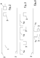
Fig. 2 schematically shows a first possible optical fibre arrangement; -
Fig. 3 schematically shows a second possible optical fibre arrangement; -
Fig. 4 schematically shows a third possible optical fibre arrangement; -
Fig. 5 schematically shows a conventional level crossing predictor; and -
Fig. 6 schematically shows a level crossing predictor in accordance with a first embodiment of the present invention. - The signature of a train will be characterised by a series of frequencies at various amplitudes caused by the passage of the wheel along the rail, in particular there will be specific peaks as an axle passes a given point. It is therefore possible to determine not only that a train has passed a particular location on the railway, but also to determine further information such as train length, the number of axles of the train, the condition of equipment on that train, and the condition of fixed equipment such as the track itself or trackside equipment.
-
Fig. 1 schematically shows a theoretical signature in the amplitude vs time domain for a train operating normally. For simplicity, the train is assumed to be simple, for example a "two-car sprinter" lightweight vehicle with substantially evenly-distributed weight along the length of the train. The signature shown reflects the acoustic signal measured by a trackside transducer over time at a set region, located away from, and out of the influence of, "noisy" equipment, and shows the approach, passage and departure of a train. At a first region A of the signature, the acoustic signal corresponds to ambient or background noise only. At region B, a train approaches the transducer, and as it approaches the noise level increases. Region C occurs as the train passes the transducer. Since the train is assumed to be simple and with evenly distributed weight, this region generally takes the form of a plateau, i.e. there is a similar noise level experienced throughout passage of the train. However, there are points D of raised signal, which occur when individual wheels of the train pass by the transducer. Region E occurs after the passage of the train, and shows a gradually diminishing noise level as the train moves away. Finally, region F shows a return to ambient or background noise only. - Although not shown in
Fig. 1 , the signature will have a characteristic spectral response in the frequency domain, which advantageously is also monitored. - It can be seen from
Fig. 1 that various types of information may be collated from the transducer's output. These include: - i) The train signature is unique for each train. Therefore comparison of detected signatures can be used to identify and differentiate trains. Furthermore trains may be tracked by means of the signature, as described below. It must be remembered though that the signature will be "squeezed" or "stretched" along the time axis depending on the speed of the train as it passes a transducer, and so compensation is necessary when identifying or tracking trains.
- ii) The number of points D corresponds to the number of axles of the train. Therefore, the transducer may be used as an axle-counter.
- iii) The profile of points D contains information as to the condition of the wheels and the condition of track where the wheels pass. If all such points D share a common unusual feature, then this implies that the track has a certain characteristic (e.g. a fault). If on the other hand a feature is only shown in one point D, then it may be implied that a particular wheel has a characteristic (e.g. a region of flattening). Furthermore the wheel affected may be determined.
- iv) Other conditions of the train may be identified. For example, a signature including a high response at certain frequencies may imply "squealing" due to a fault. An unusual profile in region E may imply that an object is dragging along behind the train for example.
- v) The signal outside the signature, i.e. the ambient noise in regions A, F, provides information on fixed equipment proximate the transducer, as will be described further below.
- It should be noted that a single such signature cannot be used alone to determine either the length of the train or its speed. In order to enable these determinations, it is necessary to acquire at least one additional signature, i.e. from second transducer region.
- There are various alternatives for providing fibre optic hydrophony proximate a track. These include:
- i) providing a "long" fibre, i.e. one which is longer than the desired resolution of the system, alongside the track. The location of the source of acoustic signals may be determined by using signal processing, as is known in the art. This type of arrangement is schematically shown in
Fig. 2 , where a single length ofoptical fibre 1 is provided alongside atrack 2. Signal detection is performed by areceiver 3 located at an end of thefibre 1.Receiver 3 is in connection with asignal processor 4. This outputs data to the main train control system (not shown). Alternatively,receiver 3 andsignal processor 4 may be integrally formed. - ii) Providing a series of discrete fibres along the track, with each fibre having a length approximately equal to the desired resolution of the system. This arrangement is schematically shown in
Fig. 3 , where a number offibres 1a are provided alongsidetrack 2, each fibre being connected to areceiver 3. This arrangement may reduce processing load. It is possible to apply signal processing to the signal received from eachfibre 1a, in order to further improve localisation of the acoustic signal source. - iii) Providing a "point" measurement with a short section of fibre to provide accurate determination of the acoustic signal source location without requiring the signal processing of i) above. This arrangement is shown in
Fig. 4 , with a number of short fibre sections 1b positioned proximate atrack 2, each section 1b being connected to areceiver 3. This arrangement may be of particular use for monitoring fixed / trackside equipment such as points, crossings etc. - As mentioned above, the present invention provides various improvements over conventional systems. Some of these are now described for illustration.
- In a first embodiment, fibre optic cables - either new or already in place alongside the railway line - are used to determine the position of trains approaching a road / rail crossing (level crossing).
-
Fig. 5 schematically shows a conventional bi-directional level crossing predictor. Here, tracks 2 are provided with a number oftreadles 5, which are activated by the physical passage of a train (not shown) as it approaches or departs from alevel crossing 6. Activation of atreadle 5 by a train approaching thelevel crossing 6 causes barriers at the crossing to lower, i.e. to block the crossing to road users. Activation of atreadle 5 by a train as it leaves the level crossing causes the barriers to raise again, so that road users may cross. With this system, the barriers are controlled based on the position of a train, i.e. whether a train has reached the location of atreadle 5. A disadvantage with such a system is that the time between the train activating atreadle 5 on the approach to thelevel crossing 6 and the train reaching thelevel crossing 6 is dependent on the speed of the train. This means that road users are not given consistent warning of approaching trains. - A way to avoid this problem would be to control barrier activation dependent upon a determined time for a train to reach the level crossing. This embodiment provides such a method by the use of fibre optic hydrophony.
- Analysis of sound vibrations detected by fibre optic hydrophony technology is used to determine when a train enters a section of interest, and to track its passage along the section of line. Since the location of the train is tracked, the speed v of the train may be determined by comparing the train's location at various times.
- The tracking of movement is then used to determine the time at which the train will arrive at the crossing, for example using a simple t = s / v calculation, where v is the speed of the train, t is the estimated time of arrival and s is the distance of the train from the level crossing. Trackside machinery such as lights and / or barriers is then operated at a fixed time before the train's arrival. The use of this technology is analogous to the use of existing track circuit-based level crossing predictors, but is completely immune to the type of traction and traction bonding being used - e.g. diesel, ac electric, dc electric etc. Conventional track circuits may not operate correctly with electric trains for example.
- As a train passes a particular point on a railway line, there is a significant amount of noise and vibration created, this being detected by the sensing fibre optic cable. A train has a clear signature, i.e. vibration amplitude and / or frequency against time characteristic which is dependent on e.g. train type, trackside infrastructure and train speed. In particular, peaks are determined when axles pass a point on the railway, or a trackside anomaly such as an insulated rail joint, track joint, set of points, or indeed specifically placed target or targets (anomalies placed on the rail) that result in a characteristic vibration as a train wheel passes over it.
- Due to the nature of train construction, and in particular the nature of the steel to steel wheel to rail interface, the signature of a train is very different to that of a car or other road vehicle. Having determined that a train is passing a particular position of the track, it is then possible to track the train as it moves towards a road crossing. By determining the time taken to travel a known distance between points on the fibre, it is possible to predict the time at which the train will arrive at the level crossing and thus provide a constant time warning to road users.
-
Fig. 6 schematically shows a level crossing detector in accordance with this embodiment, where reference numerals for similar components have been retained fromFig. 5 . Here, anoptical fibre 1 is laid proximate eachrail 2. Acoustic signals are received from two specified spaced apartlocations crossing 6. Processing means (not shown) is used to analyse the signals received fromlocations - Integrity may be further increased by determining that the signature at various points is the same as the vehicle moves along, thus ensuring that the same train is being tracked, and that there is no anomalous reading being made. This may be achieved using a pattern matching algorithm to compare received signatures. As noted previously, the signatures are compensated for the speed of the train.
- By tracking individual train signatures it is also possible to determine when a train or rail vehicle has changed direction, thus allowing safe tracking of train position regardless of direction. This is particularly relevant when works vehicles are being used on a section of railway.
- Further safety can be provided by using similar technology on the road crossing itself to track the position of road vehicles as the cross the track. Again, signatures of road vehicles are dependent on e.g. their engine, and the wheel / road interface, particularly as structures such as the rail are struck. It is therefore possible to determine that vehicles that have entered the crossing have also safely passed over it. If this is not the case, then an appropriate action can be taken by the crossing control equipment, for example warning the driver to stop. Additional optical fibre transducer may be located proximate the road to assist in this monitoring, alternatively trackside fibre may be sufficient.
- Should any doubt be raised by the tracking mechanism, then the level crossing equipment is caused to operate as a fallback fault condition.
- As a train passes a particular point on a railway line, there is a significant amount of noise and vibration created, much of this being detectable by the sensing fibre optic cable. As described above, each train has a clear signature, i.e. vibration amplitude and / or frequency against time characteristic which is dependent on e.g. train type, trackside infrastructure and train speed. In particular, peaks are determined when axles pass a point on the railway, or trackside anomaly such as an insulated rail joint, track joint, set of points, or indeed specifically placed target or targets (anomalies placed on the rail) that results in a characteristic vibration as a train wheel passes over it. Further functionality may be provided in that the signature of the train will, as described above, be dependent on the number of axles on the train, the shape, deformation and condition of the wheels, the traction systems and so on. This can allow the tracking of multiple trains in the same section of track, and distinction between them.
- In a second embodiment, train location is determined by the use of a fibre optic hydrophony system, in particular accurate determination of train position within a section of track as the the train moves along the railway. Such a system may be used with the methodology described in
GB 1007073.8 - In this embodiment, software is used to track trains safely as they move around a railway network. As in the first embodiment described above, the tracking may be performed using a pattern matching algorithm to compare received signatures. This allows the determination of train presence in 'virtual blocks' (i.e. any logical area of track), thus increasing safety of a system at potentially lower cost than conventional systems. Since the location of the acoustic signal source may be specified to the software, i.e. the software may be asked to "listen" to signals received from a particular location, the size of the virtual block can also be specified.
- By tracking individual train signatures it is also possible to determine when a train or rail vehicle has changed direction, thus allowing safe tracking of train position regardless of direction. This is particularly relevant when works vehicles are being used on a section of railway. In this case it is necessary to "listen" to signals received from at least two locations.
- The hydrophony train detection system may be overlaid with conventional detection systems, e.g. GPS, beacon, odometry, axle counters, track circuits, treadles or the like, to provide diversity, and fall-back in the event of failure of one detection system.
- In a third embodiment, train location is again determined by the use of a fibre optic hydrophony system. Here, this is not provided as a 'vital' system, but as a means of providing accurate information for applications such as "Real Time Information Systems", passenger information etc to railway stakeholders. This is particularly relevant where continuous train detection is not used and therefore positional accuracy is not certain. The fibre could for example comprise a new fibre optic cable, or a spare, dark fibre, in any existing system. Triggers could be based on either presence of noise having the signature of a train at a fixed point on the line, or by tracking movement through the section of track.
- Passenger information can therefore be determined from knowledge of the timetable combined with knowledge about the train type and its location, giving accurate predictive information to passengers as to the time at which the vehicle is likely to arrive at a particular station, or to advise passengers at a station to stand back as a non-stopping train passes the location.
- In this fourth embodiment, a fibre optic cable laid close to the trackside may be used to determine the status of moving railway assets such as rail vehicles.
- As a train passes a particular point on a railway line, there is a significant amount of noise and vibration created, much of this being detectable by the sensing fibre optic cable. A train has a clear signature, i.e. vibration amplitude and / or frequency against time characteristic which is dependent on e.g. train type, trackside infrastructure and train speed. In particular peaks are determined when axles pass a point on the railway, or trackside anomaly such as an insulated rail joint, track joint, set of points, or indeed specifically placed target or targets (anomalies placed on the rail) that results in a characteristic vibration as a train wheel passes over it.
By detecting vibrations on the outer surface of the fibre, and in particular in comparison with a prerecorded 'signature' for the particular object, it is possible to reveal faults including: - Wheels with 'flat spots'. Such a system is also known as "Wheel Impact Load Detection". As a wheel flat passes over the rail, and particularly over an anomaly such as a rail joint, or specially placed artificial anomaly, the signature of a wheel with a wheel flat passing that point is significantly different to that of a perfectly circular wheel. In particular the frequency domain analysis will show a large number of frequency components being detected due to the significant shock load placed on the wheel and track. It is also possible to check for such problems using an acoustic transducer provided on the train itself.
- Hot wheel bearings (and later consequences such as locked wheels). Increased friction will cause a changed signature as the wheel moves along the rail, as stress waves pass over the wheel rail interface. In addition expansion of components within the wheel / bogie assembly will cause the time and / or frequency domain analysis to change.
- High pressure air leaks (e.g. brake pipe or suspension components). The high frequency 'whistling' caused by such faults are easily picked up as the train travels past the sensing devices, resulting in a clearly identifiable profile in the frequency / time signature.
- Pantograph (the apparatus used to pick up energy from overhead cables) high voltage arcs cause a 'white noise' which manifests itself as high amplitude components at a wide range of frequencies within the range of detection of the hydrophony system.
- Dragging equipment which has fallen from a train, as it is dragged along the ballast will casue the train's signature to be radically changed, thus allowing feedback to be provided to the driver either through the railway signalling system, or through a message passed to the control centre.
- Decoupled / uncoupled trains. Analysis of the received signature may be used to determine if a train has split, for example by counting the number of axle peaks.
- In this fifth embodiment, a fibre optic cable laid close to the trackside may be used to determine the status of fixed railway assets such as point machines, level crossing barriers and so on.
- The vibration caused by the moving parts of the equipment will cause the outer layer of the fibre optic cable to vibrate, and this is picked up by the sensing equipment. Measurements of the signature of healthy equipment are made and recorded, in particular characteristics such as time of operation, and peaks of amplitude or vibration as areas of high friction are encountered.
- By detecting vibrations on the outer surface of the fibre, and in particular in comparison with a prerecorded 'signature' for the particular object, it is possible to reveal fixed asset faults including:
- Track deformation, for example torsion of the rail or gauge corner cracking. As the train moves along the rail, the signature detected will be different to the 'normal' signature, for all axles, thus allowing detection with some surety that that rail is not as expected and that further inspection is required.
- Switch and crossings suffering increased friction or slower operational times.
- Point machines where condition is not optimal.
- By using computer algorithms to determine trends in such characteristics, the system can determine at which point maintenance is required.
- By adopting such a technique, no routine maintenance may be required, all maintenance can be based entirely upon the condition and operational status of the device being monitored.
- Furthermore, this technique may be used to monitor vandalism, trespassing or theft at railside locations. If the noise expected to be created by an item disappears from a received signal, then this implies that the item has been physically removed, e.g. by theft. Abnormal signals received from an item may indicate vandalism of that item. In addition, the acoustic monitoring may be able to detect items not associated with the railway, e.g. monitoring intruders directly, for example footsteps, talking, or vehicles.
- Various alternatives and modifications within the scope of the invention will be apparent to those skilled in the art. For example, although the foregoing description relates exclusively to the use of fibre optic hydrophony, where the acoustic transducer comprises a fibre optic cable, other forms of acoustic transducer may be used, for example microphones.
- Preferably, the acoustic signals are monitored continuously, however this may not be necessary for all applications.
- In the event of ambiguity in the interpretation of the received signal, it may be played to a human operator, who may be able to identify the noise picked up.
- The methodology described above may be used in combination, e.g. the same received signals may be used both for train location and for monitoring of fixed assets.
Claims (15)
- A method of monitoring components of a railway system which includes a track and at least one train that is operable to run on said track, comprising the steps of:a) providing an acoustic transducer proximate the railway for picking up acoustic signals;b) receiving signals from the transducer; andc) analysing the received signals.
- A method according to claim 1, wherein step c) comprises identifying a signature of a train.
- A method according to claim 2, wherein step c) further comprises determining the condition of the track.
- A method according to any preceding claim, wherein step c) comprises identifying a signature associated with fixed assets, wherein the fixed assets comprise at least one asset selected from the group including: points, point machines, level crossings, cables, switches, track.
- A method according to claim 4, wherein the fixed assets have moving parts and the method includes moving these moving parts and picking up the acoustic signals resulting from these movements.
- A method according to claim 5, wherein analyzing the received signals includes identifying time of operation or peaks of amplitude.
- A method according to any preceding claim, comprising the step of placing a target on the track to generate vibration as a train wheel passes over it.
- A method according to any preceding claim, wherein the or each acoustic transducer comprises an optical fibre.
- A method according to any preceding claim, wherein the received signals are analyzed in frequency domain.
- A method according to any preceding claim, wherein the received signals are analyzed in time domain for a signature which indicates an axle of a train passing the transducer.
- A method according to claim 10, wherein the signature is analyzed for unusual features.
- A method according to claim 11, wherein the analysis establishes whether all signatures which belong to one train have this unusual feature or only one signature.
- A method according to claim 12, if only one signature has such unusual feature, determining which axel and/or which wheel is affected.
- A method according to any preceding claim, wherein the received signals are analyzed by making a comparison with prerecorded signatures.
- A method according to any preceding claim, wherein the received signals are analyzed for an anomaly, such as an insulated rail joint, track joint, set of points, or specifically placed target that result in a characteristic vibration as a train wheel passes over it.
Priority Applications (2)
| Application Number | Priority Date | Filing Date | Title |
|---|---|---|---|
| EP20192266.3A EP3766757A3 (en) | 2009-09-03 | 2010-09-03 | Railway systems using acoustic monitoring |
| EP20192265.5A EP3792142A3 (en) | 2009-09-03 | 2010-09-03 | Railway apparatus and method using acoustic monitoring |
Applications Claiming Priority (3)
| Application Number | Priority Date | Filing Date | Title |
|---|---|---|---|
| GBGB0915322.2A GB0915322D0 (en) | 2009-09-03 | 2009-09-03 | Railway systems using fibre optic hydrophony systems |
| EP10752138.7A EP2473392B1 (en) | 2009-09-03 | 2010-09-03 | Railway systems using acoustic monitoring |
| PCT/GB2010/051467 WO2011027166A1 (en) | 2009-09-03 | 2010-09-03 | Railway systems using acoustic monitoring |
Related Parent Applications (2)
| Application Number | Title | Priority Date | Filing Date |
|---|---|---|---|
| EP10752138.7A Division EP2473392B1 (en) | 2009-09-03 | 2010-09-03 | Railway systems using acoustic monitoring |
| EP10752138.7A Division-Into EP2473392B1 (en) | 2009-09-03 | 2010-09-03 | Railway systems using acoustic monitoring |
Related Child Applications (4)
| Application Number | Title | Priority Date | Filing Date |
|---|---|---|---|
| EP20192265.5A Division-Into EP3792142A3 (en) | 2009-09-03 | 2010-09-03 | Railway apparatus and method using acoustic monitoring |
| EP20192265.5A Division EP3792142A3 (en) | 2009-09-03 | 2010-09-03 | Railway apparatus and method using acoustic monitoring |
| EP20192266.3A Division-Into EP3766757A3 (en) | 2009-09-03 | 2010-09-03 | Railway systems using acoustic monitoring |
| EP20192266.3A Division EP3766757A3 (en) | 2009-09-03 | 2010-09-03 | Railway systems using acoustic monitoring |
Publications (3)
| Publication Number | Publication Date |
|---|---|
| EP3281840A2 true EP3281840A2 (en) | 2018-02-14 |
| EP3281840A3 EP3281840A3 (en) | 2018-05-30 |
| EP3281840B1 EP3281840B1 (en) | 2021-07-07 |
Family
ID=41203079
Family Applications (5)
| Application Number | Title | Priority Date | Filing Date |
|---|---|---|---|
| EP10752138.7A Revoked EP2473392B1 (en) | 2009-09-03 | 2010-09-03 | Railway systems using acoustic monitoring |
| EP20192265.5A Pending EP3792142A3 (en) | 2009-09-03 | 2010-09-03 | Railway apparatus and method using acoustic monitoring |
| EP16153126.4A Active EP3050774B2 (en) | 2009-09-03 | 2010-09-03 | Railway systems using acoustic monitoring |
| EP17186360.8A Active EP3281840B1 (en) | 2009-09-03 | 2010-09-03 | Method for monitoring components of a railway system |
| EP20192266.3A Pending EP3766757A3 (en) | 2009-09-03 | 2010-09-03 | Railway systems using acoustic monitoring |
Family Applications Before (3)
| Application Number | Title | Priority Date | Filing Date |
|---|---|---|---|
| EP10752138.7A Revoked EP2473392B1 (en) | 2009-09-03 | 2010-09-03 | Railway systems using acoustic monitoring |
| EP20192265.5A Pending EP3792142A3 (en) | 2009-09-03 | 2010-09-03 | Railway apparatus and method using acoustic monitoring |
| EP16153126.4A Active EP3050774B2 (en) | 2009-09-03 | 2010-09-03 | Railway systems using acoustic monitoring |
Family Applications After (1)
| Application Number | Title | Priority Date | Filing Date |
|---|---|---|---|
| EP20192266.3A Pending EP3766757A3 (en) | 2009-09-03 | 2010-09-03 | Railway systems using acoustic monitoring |
Country Status (8)
| Country | Link |
|---|---|
| US (1) | US8985523B2 (en) |
| EP (5) | EP2473392B1 (en) |
| CA (1) | CA2771468C (en) |
| DK (2) | DK3281840T3 (en) |
| ES (3) | ES2662744T3 (en) |
| GB (1) | GB0915322D0 (en) |
| PT (2) | PT3281840T (en) |
| WO (1) | WO2011027166A1 (en) |
Cited By (3)
| Publication number | Priority date | Publication date | Assignee | Title |
|---|---|---|---|---|
| WO2019179696A1 (en) * | 2018-03-22 | 2019-09-26 | Siemens Rail Automation Holdings Limited | Sensor unit for detecting the approach of a train and system with said sensor unit |
| EP3643580A1 (en) * | 2018-10-23 | 2020-04-29 | Greatcom AG | Monitoring system and method for detecting traffic objects in a surveillance area |
| WO2021183080A1 (en) * | 2020-03-09 | 2021-09-16 | Gokmen Sabri Haluk | Method for detection of track leveling errors by vibration measurement from rails |
Families Citing this family (58)
| Publication number | Priority date | Publication date | Assignee | Title |
|---|---|---|---|---|
| US9733625B2 (en) | 2006-03-20 | 2017-08-15 | General Electric Company | Trip optimization system and method for a train |
| US10569792B2 (en) | 2006-03-20 | 2020-02-25 | General Electric Company | Vehicle control system and method |
| US10308265B2 (en) | 2006-03-20 | 2019-06-04 | Ge Global Sourcing Llc | Vehicle control system and method |
| US9950722B2 (en) | 2003-01-06 | 2018-04-24 | General Electric Company | System and method for vehicle control |
| US9828010B2 (en) | 2006-03-20 | 2017-11-28 | General Electric Company | System, method and computer software code for determining a mission plan for a powered system using signal aspect information |
| US9481384B2 (en) | 2012-11-21 | 2016-11-01 | General Electric Company | Route examining system and method |
| GB0915322D0 (en) * | 2009-09-03 | 2009-10-07 | Westinghouse Brake & Signal | Railway systems using fibre optic hydrophony systems |
| US8500071B2 (en) * | 2009-10-27 | 2013-08-06 | Invensys Rail Corporation | Method and apparatus for bi-directional downstream adjacent crossing signaling |
| NO331979B1 (en) * | 2010-09-17 | 2012-05-14 | Stiftelsen Norsar | System and method for early detection of trains |
| WO2012039776A1 (en) * | 2010-09-24 | 2012-03-29 | QinetiQ North America, Inc. | Airport incursion notification system |
| ES2422905T3 (en) * | 2011-03-25 | 2013-09-16 | Thales Deutschland Gmbh | Detector for the detection of a cold movement of a railway vehicle and method for its operation |
| GB201201768D0 (en) * | 2012-02-01 | 2012-03-14 | Qinetiq Ltd | Control of transport networks |
| GB201201703D0 (en) | 2012-02-01 | 2012-03-14 | Qinetiq Ltd | Detecting train separation |
| US8725405B2 (en) * | 2012-04-13 | 2014-05-13 | General Electric Company | Methods and system for crossing prediction |
| DE102012213495A1 (en) | 2012-07-31 | 2014-02-06 | Siemens Aktiengesellschaft | Rail Vehicle Tracking |
| DE102012213487A1 (en) | 2012-07-31 | 2014-02-06 | Siemens Aktiengesellschaft | Rail Vehicle Tracking |
| DE102012213499A1 (en) | 2012-07-31 | 2014-02-06 | Siemens Aktiengesellschaft | vehicle tracking |
| DE102012217620A1 (en) | 2012-09-27 | 2014-03-27 | Siemens Aktiengesellschaft | Method for operating a mobile device in a railway system, railway system and mobile device |
| DE102012217627A1 (en) | 2012-09-27 | 2014-03-27 | Siemens Aktiengesellschaft | Method for operating a rail vehicle in a railway system and railway system |
| US9682716B2 (en) | 2012-11-21 | 2017-06-20 | General Electric Company | Route examining system and method |
| US9669851B2 (en) | 2012-11-21 | 2017-06-06 | General Electric Company | Route examination system and method |
| DE102012222471A1 (en) * | 2012-12-06 | 2014-06-12 | Siemens Aktiengesellschaft | vehicle tracking |
| CN105636853B (en) * | 2013-07-31 | 2018-04-24 | 铁路视像有限公司 | For obstacle recognition and the system and method avoided |
| EP2862778B1 (en) * | 2013-10-15 | 2017-01-04 | Bayern Engineering GmbH & Co. KG | Method for generating measurement results from sensor signals |
| TR201405723A2 (en) * | 2014-05-22 | 2015-09-21 | Sabri Haluk Goekmen | System which senses rail fractures and cracks through the method of reflection |
| CN104020221B (en) * | 2014-05-30 | 2017-06-16 | 杨媛 | A kind of real-time broken rail detection localization method based on supersonic guide-wave |
| GB201414616D0 (en) | 2014-08-18 | 2014-10-01 | Optasense Holdings Ltd | Detection of anomalies in rail wheelsets |
| DE102014113669A1 (en) * | 2014-09-22 | 2016-03-24 | Bombardier Transportation Gmbh | Method for determining the state in a rail vehicle |
| CA2870425C (en) * | 2014-11-12 | 2015-12-29 | Frank C. Van Der Merwe | Automated in motion railway seismic wheel failure detection system |
| CN104554348A (en) * | 2014-12-08 | 2015-04-29 | 河南思维信息技术有限公司 | Locomotive operation real-time analysis method and locomotive operation real-time analysis device |
| CN104960551A (en) * | 2015-06-25 | 2015-10-07 | 北京交通大学 | Unattended system for sensing railway field operation and protection based on photonic crystal fiber |
| US10513280B2 (en) | 2015-10-20 | 2019-12-24 | International Electronic Machines Corp. | Operations monitoring for effect mitigation |
| GB201521116D0 (en) * | 2015-11-30 | 2016-01-13 | Optasense Holdings Ltd | Tracking using distributed fibre optic sensing |
| DE102016108273A1 (en) * | 2016-05-04 | 2017-11-09 | senvisys UG (haftungsbeschränkt) | Method for evaluating signals of at least one vibration sensor |
| DE102016210968A1 (en) | 2016-06-20 | 2017-12-21 | Siemens Aktiengesellschaft | Method for operating a locating device and locating device |
| GB201611326D0 (en) * | 2016-06-29 | 2016-08-10 | Optasense Holdings Ltd | Distributed fibre optic sensing for rail monitoring |
| EP3275763B1 (en) * | 2016-07-27 | 2021-09-15 | Frauscher sensortechnik GmbH | Sensor arrangement for railway monitoring and corresponding method |
| DE102016214024A1 (en) * | 2016-07-29 | 2018-02-01 | Siemens Aktiengesellschaft | Method and system for influencing track-bound vehicles |
| US10124819B2 (en) * | 2016-08-08 | 2018-11-13 | General Electric Company | Wheel deformity warning system |
| WO2018090106A1 (en) * | 2016-11-21 | 2018-05-24 | Rail Control Systems Australia Pty Ltd | Speed proving method and apparatus |
| US10773742B2 (en) * | 2017-09-13 | 2020-09-15 | Siemens Industry, Inc. | Advanced preemption using the wayside inspector and wireless magnetometer sensors |
| DE102017217450A1 (en) * | 2017-09-29 | 2019-04-04 | Siemens Mobility GmbH | Method for determining the state of at least one catenary running along a route |
| KR20190064035A (en) * | 2017-11-30 | 2019-06-10 | (주)넷케이티아이 | System for monitoring railroading status based on distributed acoustic sensor and a method thereof |
| JP7127997B2 (en) * | 2018-03-15 | 2022-08-30 | 株式会社京三製作所 | Railroad crossing warning time calculator |
| RU2681451C1 (en) * | 2018-03-30 | 2019-03-06 | Дмитрий Викторович Ефанов | Safety in the railway crossing ensuring method |
| US11055984B2 (en) * | 2018-04-10 | 2021-07-06 | Network Integrity Systems, Inc. | Monitoring a sensor output to determine intrusion events |
| CN108791359A (en) * | 2018-05-08 | 2018-11-13 | 成都九壹通智能科技股份有限公司 | The automatic control system of track switch conversion |
| CN108622135A (en) * | 2018-05-08 | 2018-10-09 | 成都九壹通智能科技股份有限公司 | Track switch automatic control system and method |
| CN108639101A (en) * | 2018-05-08 | 2018-10-12 | 成都九壹通智能科技股份有限公司 | The early warning system that track switch automatically controls |
| CN108791360A (en) * | 2018-05-09 | 2018-11-13 | 成都九壹通智能科技股份有限公司 | Track switch remote control system |
| AU2019333159B2 (en) * | 2018-08-30 | 2022-07-28 | Voestalpine Signaling Usa Inc. | Railcar acoustic monitoring system and method of use |
| US11408988B2 (en) | 2018-09-24 | 2022-08-09 | Howden Alphair Ventilating Systems Inc. | System and method for acoustic vehicle location tracking |
| US11124211B2 (en) * | 2018-12-07 | 2021-09-21 | Alstom Transport Technologies | Methods and devices for locating a railway vehicle |
| DE102018222723A1 (en) | 2018-12-21 | 2020-06-25 | Siemens Mobility GmbH | Method and device for object detection |
| CN110329116B (en) * | 2019-08-01 | 2022-07-22 | 南京拓控信息科技股份有限公司 | Automatic neutral section passing detection device and detection method for electric locomotive |
| US20210253149A1 (en) * | 2020-02-14 | 2021-08-19 | International Electronic Machines Corporation | Methods and systems for monitoring a transportation path with acoustic or vibration sensing |
| US20230356763A1 (en) * | 2020-09-14 | 2023-11-09 | Konux Gmbh | Monitoring passing trains, system and method |
| WO2023129052A2 (en) * | 2021-12-29 | 2023-07-06 | Gokmen Sabri Haluk | Acoustic method for detecting flood, landslide and under-rail washout problems resulting from natural disasters in railways |
Citations (1)
| Publication number | Priority date | Publication date | Assignee | Title |
|---|---|---|---|---|
| DE102007006833A1 (en) | 2007-02-07 | 2008-08-14 | Deutsches Zentrum für Luft- und Raumfahrt e.V. | Action e.g. switching operation, triggering device for railway system, has sensors detecting acoustic signals, where device detects rail-mounted vehicle located on track system based on signals and triggers action based on vehicle detection |
Family Cites Families (26)
| Publication number | Priority date | Publication date | Assignee | Title |
|---|---|---|---|---|
| US580304A (en) * | 1897-04-06 | Sylvania | ||
| GB137433A (en) * | 1919-03-22 | 1920-01-15 | John Gardner | Improvements in electric signalling controlled by mechanical vibrations |
| US4843885A (en) * | 1987-10-02 | 1989-07-04 | Servo Corporation Of America | Acoustic detection of bearing defects |
| CH679847A5 (en) | 1990-01-12 | 1992-04-30 | Bruno Mueller | |
| US5029477A (en) * | 1990-01-31 | 1991-07-09 | Servo Corporation Of America | Integrity test for acoustic bearing defect detector |
| DE4214580A1 (en) * | 1992-04-30 | 1993-11-04 | Deutsche Aerospace | Detecting approaching train during track work - uses electro-acoustic transducers, whose output signals are amplified and fed to optical or audible alarm system |
| DE4214271A1 (en) * | 1992-04-30 | 1993-11-04 | Deutsche Aerospace | Detecting approaching train during track work - uses acoustic sensors, whose output signals are fed to alarm system after amplification |
| IT1262407B (en) * | 1993-09-06 | 1996-06-19 | Finmeccanica Spa | INSTRUMENTATION USING INTEGRATED OPTIC COMPONENTS FOR DIAGNOSTICS OF PARTS WITH FIBER OPTIC SENSORS INCLUDED OR FIXED ON THE SURFACE. |
| WO1997025235A1 (en) * | 1996-01-12 | 1997-07-17 | Pace Joseph A | Railroad traffic warning system apparatus and method therefor |
| US5713540A (en) * | 1996-06-26 | 1998-02-03 | At&T Corp. | Method and apparatus for detecting railway activity |
| CA2212063A1 (en) * | 1997-08-29 | 1999-02-28 | Robert Douglas Stephens | Railway hazard vibration sensing, locating and alarm system |
| DE19913057A1 (en) * | 1999-03-17 | 2000-09-21 | Siemens Ag | Wheel counting and detecting method e.g. for rail-borne vehicles such as trains |
| EP1128171A1 (en) * | 2000-02-22 | 2001-08-29 | Sensor Line Gesellschaft für optoelektronische Sensoren mbH | Fibre optic load sensor for detecting railway vehicles |
| US6830224B2 (en) * | 2001-02-26 | 2004-12-14 | Railroad Transportation Communication Technologies (Rtct) Llc | Rail communications system |
| US7254467B2 (en) * | 2003-02-13 | 2007-08-07 | General Electric Company | Digital train system for automatically detecting trains approaching a crossing |
| US6951132B2 (en) * | 2003-06-27 | 2005-10-04 | General Electric Company | Rail and train monitoring system and method |
| US8702043B2 (en) * | 2010-09-28 | 2014-04-22 | General Electric Company | Rail vehicle control communication system and method for communicating with a rail vehicle |
| ITBN20060004A1 (en) † | 2006-09-20 | 2006-12-20 | Antonello Cutolo | FIBER OPTIC TRANSMISSION SYSTEM FOR THE PARAMETER MONITORING AND THE IMPROVEMENT OF THE SAFETY OF A RAILWAY LINE |
| US7693673B2 (en) * | 2007-06-06 | 2010-04-06 | General Electric Company | Apparatus and method for identifying a defect and/or operating characteristic of a system |
| AU2008271145A1 (en) * | 2007-06-27 | 2009-01-08 | Amsted Rail Company, Inc. | Acoustic monitoring of railcar running gear and railcars |
| DE102007041174A1 (en) * | 2007-08-27 | 2009-02-26 | Siemens Ag | Device for identification of technically unprotected level crossing, has traffic signs for carrying out signaling for road traffic user and sensor, which responds to approaching train |
| WO2009043109A1 (en) * | 2007-10-05 | 2009-04-09 | United Group Rail Services Limited | Railroad vigilance system control unit |
| US7922127B2 (en) * | 2008-04-28 | 2011-04-12 | General Electric Company | System and method for pacing a powered system traveling along a route |
| US8583299B2 (en) * | 2009-03-17 | 2013-11-12 | General Electric Company | System and method for communicating data in a train having one or more locomotive consists |
| GB0915322D0 (en) * | 2009-09-03 | 2009-10-07 | Westinghouse Brake & Signal | Railway systems using fibre optic hydrophony systems |
| US8651434B2 (en) * | 2010-10-26 | 2014-02-18 | General Electric Company | Methods and systems for rail communication |
-
2009
- 2009-09-03 GB GBGB0915322.2A patent/GB0915322D0/en not_active Ceased
-
2010
- 2010-09-03 ES ES10752138.7T patent/ES2662744T3/en active Active
- 2010-09-03 DK DK17186360.8T patent/DK3281840T3/en active
- 2010-09-03 ES ES17186360T patent/ES2891350T3/en active Active
- 2010-09-03 WO PCT/GB2010/051467 patent/WO2011027166A1/en active Application Filing
- 2010-09-03 EP EP10752138.7A patent/EP2473392B1/en not_active Revoked
- 2010-09-03 ES ES16153126T patent/ES2662877T5/en active Active
- 2010-09-03 DK DK10752138.7T patent/DK2473392T3/en active
- 2010-09-03 EP EP20192265.5A patent/EP3792142A3/en active Pending
- 2010-09-03 EP EP16153126.4A patent/EP3050774B2/en active Active
- 2010-09-03 US US13/393,950 patent/US8985523B2/en active Active
- 2010-09-03 CA CA2771468A patent/CA2771468C/en active Active
- 2010-09-03 PT PT171863608T patent/PT3281840T/en unknown
- 2010-09-03 EP EP17186360.8A patent/EP3281840B1/en active Active
- 2010-09-03 EP EP20192266.3A patent/EP3766757A3/en active Pending
- 2010-09-03 PT PT107521387T patent/PT2473392T/en unknown
Patent Citations (1)
| Publication number | Priority date | Publication date | Assignee | Title |
|---|---|---|---|---|
| DE102007006833A1 (en) | 2007-02-07 | 2008-08-14 | Deutsches Zentrum für Luft- und Raumfahrt e.V. | Action e.g. switching operation, triggering device for railway system, has sensors detecting acoustic signals, where device detects rail-mounted vehicle located on track system based on signals and triggers action based on vehicle detection |
Cited By (5)
| Publication number | Priority date | Publication date | Assignee | Title |
|---|---|---|---|---|
| WO2019179696A1 (en) * | 2018-03-22 | 2019-09-26 | Siemens Rail Automation Holdings Limited | Sensor unit for detecting the approach of a train and system with said sensor unit |
| US11801878B2 (en) | 2018-03-22 | 2023-10-31 | Siemens Mobility Limited | Sensor unit for detecting the approach of a train and system with said sensor unit |
| EP3643580A1 (en) * | 2018-10-23 | 2020-04-29 | Greatcom AG | Monitoring system and method for detecting traffic objects in a surveillance area |
| CH715491A1 (en) * | 2018-10-23 | 2020-04-30 | Greatcom Ag | Monitoring system and method for detecting road users in a detection area. |
| WO2021183080A1 (en) * | 2020-03-09 | 2021-09-16 | Gokmen Sabri Haluk | Method for detection of track leveling errors by vibration measurement from rails |
Also Published As
| Publication number | Publication date |
|---|---|
| EP3281840B1 (en) | 2021-07-07 |
| EP3766757A3 (en) | 2021-04-28 |
| PT3281840T (en) | 2021-07-28 |
| WO2011027166A1 (en) | 2011-03-10 |
| EP2473392B1 (en) | 2017-12-13 |
| EP3050774A1 (en) | 2016-08-03 |
| US8985523B2 (en) | 2015-03-24 |
| CA2771468C (en) | 2016-10-18 |
| ES2662877T5 (en) | 2021-09-07 |
| DK2473392T3 (en) | 2018-02-12 |
| EP3792142A2 (en) | 2021-03-17 |
| CA2771468A1 (en) | 2011-03-10 |
| US20120217351A1 (en) | 2012-08-30 |
| DK3281840T3 (en) | 2021-08-02 |
| ES2662744T3 (en) | 2018-04-09 |
| EP3281840A3 (en) | 2018-05-30 |
| EP2473392A1 (en) | 2012-07-11 |
| EP3766757A2 (en) | 2021-01-20 |
| GB0915322D0 (en) | 2009-10-07 |
| EP3050774B1 (en) | 2017-12-13 |
| PT2473392T (en) | 2018-01-18 |
| ES2891350T3 (en) | 2022-01-27 |
| EP3792142A3 (en) | 2021-04-14 |
| EP3050774B2 (en) | 2020-11-11 |
| ES2662877T3 (en) | 2018-04-10 |
Similar Documents
| Publication | Publication Date | Title |
|---|---|---|
| EP2473392B1 (en) | Railway systems using acoustic monitoring | |
| RU2729135C1 (en) | Evaluation unit for arrangement of sensors for railway monitoring, arrangement of sensors and corresponding method | |
| EP2809565B2 (en) | Detecting train separation | |
| CN106662483B (en) | Anomaly detection in a rail wheel set | |
| AU2014323587B2 (en) | System and method for identifying damaged sections of a route | |
| US7213789B1 (en) | System for detection of defects in railroad car wheels | |
| RU2008110175A (en) | SYSTEM AND METHOD FOR DETECTING CHANGE IN THE RAILWAY OR OBSTACLE ON IT | |
| RU2618660C1 (en) | Railway traffic interval regulation system based on radio channels | |
| EP1097076A1 (en) | Method and apparatus for detecting defective track wheels | |
| US20210253149A1 (en) | Methods and systems for monitoring a transportation path with acoustic or vibration sensing | |
| KR20160103734A (en) | Monitoring system for vehicle running information by vibration analysis to predict danger | |
| US20230415796A1 (en) | Method for monitoring a railway track and monitoring unit for monitoring a railway track | |
| JP2023100442A (en) | Operation restart determination device and operation restarting support system | |
| KR20230085521A (en) | railway and train monitoring system |
Legal Events
| Date | Code | Title | Description |
|---|---|---|---|
| PUAI | Public reference made under article 153(3) epc to a published international application that has entered the european phase |
Free format text: ORIGINAL CODE: 0009012 |
|
| STAA | Information on the status of an ep patent application or granted ep patent |
Free format text: STATUS: THE APPLICATION HAS BEEN PUBLISHED |
|
| AC | Divisional application: reference to earlier application |
Ref document number: 2473392 Country of ref document: EP Kind code of ref document: P |
|
| AK | Designated contracting states |
Kind code of ref document: A2 Designated state(s): AL AT BE BG CH CY CZ DE DK EE ES FI FR GB GR HR HU IE IS IT LI LT LU LV MC MK MT NL NO PL PT RO SE SI SK SM TR |
|
| PUAL | Search report despatched |
Free format text: ORIGINAL CODE: 0009013 |
|
| AK | Designated contracting states |
Kind code of ref document: A3 Designated state(s): AL AT BE BG CH CY CZ DE DK EE ES FI FR GB GR HR HU IE IS IT LI LT LU LV MC MK MT NL NO PL PT RO SE SI SK SM TR |
|
| RIC1 | Information provided on ipc code assigned before grant |
Ipc: B61L 27/00 20060101AFI20180423BHEP Ipc: B61L 25/02 20060101ALI20180423BHEP |
|
| STAA | Information on the status of an ep patent application or granted ep patent |
Free format text: STATUS: REQUEST FOR EXAMINATION WAS MADE |
|
| 17P | Request for examination filed |
Effective date: 20181130 |
|
| RBV | Designated contracting states (corrected) |
Designated state(s): AL AT BE BG CH CY CZ DE DK EE ES FI FR GB GR HR HU IE IS IT LI LT LU LV MC MK MT NL NO PL PT RO SE SI SK SM TR |
|
| STAA | Information on the status of an ep patent application or granted ep patent |
Free format text: STATUS: EXAMINATION IS IN PROGRESS |
|
| TPAC | Observations filed by third parties |
Free format text: ORIGINAL CODE: EPIDOSNTIPA |
|
| 17Q | First examination report despatched |
Effective date: 20190508 |
|
| RAP1 | Party data changed (applicant data changed or rights of an application transferred) |
Owner name: SIEMENS MOBILITY LIMITED |
|
| RIC1 | Information provided on ipc code assigned before grant |
Ipc: B61L 1/06 20060101ALI20200818BHEP Ipc: B61L 27/00 20060101AFI20200818BHEP Ipc: B61L 25/02 20060101ALN20200818BHEP |
|
| RIC1 | Information provided on ipc code assigned before grant |
Ipc: B61L 27/00 20060101AFI20200908BHEP Ipc: B61L 25/02 20060101ALN20200908BHEP Ipc: B61L 1/06 20060101ALI20200908BHEP |
|
| STAA | Information on the status of an ep patent application or granted ep patent |
Free format text: STATUS: EXAMINATION IS IN PROGRESS |
|
| RIC1 | Information provided on ipc code assigned before grant |
Ipc: B61L 1/06 20060101ALI20201123BHEP Ipc: B61L 25/02 20060101ALN20201123BHEP Ipc: B61L 27/00 20060101AFI20201123BHEP |
|
| RIC1 | Information provided on ipc code assigned before grant |
Ipc: B61L 25/02 20060101ALN20201204BHEP Ipc: B61L 1/06 20060101AFI20201204BHEP Ipc: B61L 23/04 20060101ALI20201204BHEP |
|
| REG | Reference to a national code |
Ref country code: DE Ref legal event code: R079 Ref document number: 602010067250 Country of ref document: DE Free format text: PREVIOUS MAIN CLASS: B61L0027000000 Ipc: B61L0001060000 |
|
| GRAP | Despatch of communication of intention to grant a patent |
Free format text: ORIGINAL CODE: EPIDOSNIGR1 |
|
| STAA | Information on the status of an ep patent application or granted ep patent |
Free format text: STATUS: GRANT OF PATENT IS INTENDED |
|
| RIC1 | Information provided on ipc code assigned before grant |
Ipc: B61L 25/02 20060101ALN20210128BHEP Ipc: B61L 27/00 20060101ALI20210128BHEP Ipc: B61L 1/06 20060101AFI20210128BHEP |
|
| INTG | Intention to grant announced |
Effective date: 20210212 |
|
| RIN1 | Information on inventor provided before grant (corrected) |
Inventor name: CHAPMAN, MIKE Inventor name: PRIEST, IAN Inventor name: MCQUILLAN, JAMES Inventor name: CHADWICK, SIMON Inventor name: GLOVER, MARK |
|
| GRAS | Grant fee paid |
Free format text: ORIGINAL CODE: EPIDOSNIGR3 |
|
| RAP3 | Party data changed (applicant data changed or rights of an application transferred) |
Owner name: SIEMENS MOBILITY LIMITED |
|
| GRAA | (expected) grant |
Free format text: ORIGINAL CODE: 0009210 |
|
| STAA | Information on the status of an ep patent application or granted ep patent |
Free format text: STATUS: THE PATENT HAS BEEN GRANTED |
|
| AC | Divisional application: reference to earlier application |
Ref document number: 2473392 Country of ref document: EP Kind code of ref document: P |
|
| AK | Designated contracting states |
Kind code of ref document: B1 Designated state(s): AL AT BE BG CH CY CZ DE DK EE ES FI FR GB GR HR HU IE IS IT LI LT LU LV MC MK MT NL NO PL PT RO SE SI SK SM TR |
|
| REG | Reference to a national code |
Ref country code: GB Ref legal event code: FG4D |
|
| REG | Reference to a national code |
Ref country code: AT Ref legal event code: REF Ref document number: 1408314 Country of ref document: AT Kind code of ref document: T Effective date: 20210715 |
|
| REG | Reference to a national code |
Ref country code: PT Ref legal event code: SC4A Ref document number: 3281840 Country of ref document: PT Date of ref document: 20210728 Kind code of ref document: T Free format text: AVAILABILITY OF NATIONAL TRANSLATION Effective date: 20210722 |
|
| REG | Reference to a national code |
Ref country code: DE Ref legal event code: R096 Ref document number: 602010067250 Country of ref document: DE |
|
| REG | Reference to a national code |
Ref country code: DK Ref legal event code: T3 Effective date: 20210726 |
|
| REG | Reference to a national code |
Ref country code: IE Ref legal event code: FG4D |
|
| REG | Reference to a national code |
Ref country code: SE Ref legal event code: TRGR |
|
| REG | Reference to a national code |
Ref country code: NL Ref legal event code: FP |
|
| REG | Reference to a national code |
Ref country code: FI Ref legal event code: FGE |
|
| REG | Reference to a national code |
Ref country code: LT Ref legal event code: MG9D |
|
| REG | Reference to a national code |
Ref country code: ES Ref legal event code: FG2A Ref document number: 2891350 Country of ref document: ES Kind code of ref document: T3 Effective date: 20220127 |
|
| PG25 | Lapsed in a contracting state [announced via postgrant information from national office to epo] |
Ref country code: HR Free format text: LAPSE BECAUSE OF FAILURE TO SUBMIT A TRANSLATION OF THE DESCRIPTION OR TO PAY THE FEE WITHIN THE PRESCRIBED TIME-LIMIT Effective date: 20210707 Ref country code: NO Free format text: LAPSE BECAUSE OF FAILURE TO SUBMIT A TRANSLATION OF THE DESCRIPTION OR TO PAY THE FEE WITHIN THE PRESCRIBED TIME-LIMIT Effective date: 20211007 Ref country code: LT Free format text: LAPSE BECAUSE OF FAILURE TO SUBMIT A TRANSLATION OF THE DESCRIPTION OR TO PAY THE FEE WITHIN THE PRESCRIBED TIME-LIMIT Effective date: 20210707 Ref country code: BG Free format text: LAPSE BECAUSE OF FAILURE TO SUBMIT A TRANSLATION OF THE DESCRIPTION OR TO PAY THE FEE WITHIN THE PRESCRIBED TIME-LIMIT Effective date: 20211007 |
|
| PG25 | Lapsed in a contracting state [announced via postgrant information from national office to epo] |
Ref country code: PL Free format text: LAPSE BECAUSE OF FAILURE TO SUBMIT A TRANSLATION OF THE DESCRIPTION OR TO PAY THE FEE WITHIN THE PRESCRIBED TIME-LIMIT Effective date: 20210707 Ref country code: LV Free format text: LAPSE BECAUSE OF FAILURE TO SUBMIT A TRANSLATION OF THE DESCRIPTION OR TO PAY THE FEE WITHIN THE PRESCRIBED TIME-LIMIT Effective date: 20210707 Ref country code: GR Free format text: LAPSE BECAUSE OF FAILURE TO SUBMIT A TRANSLATION OF THE DESCRIPTION OR TO PAY THE FEE WITHIN THE PRESCRIBED TIME-LIMIT Effective date: 20211008 |
|
| REG | Reference to a national code |
Ref country code: DE Ref legal event code: R097 Ref document number: 602010067250 Country of ref document: DE |
|
| PLBE | No opposition filed within time limit |
Free format text: ORIGINAL CODE: 0009261 |
|
| STAA | Information on the status of an ep patent application or granted ep patent |
Free format text: STATUS: NO OPPOSITION FILED WITHIN TIME LIMIT |
|
| PG25 | Lapsed in a contracting state [announced via postgrant information from national office to epo] |
Ref country code: SM Free format text: LAPSE BECAUSE OF FAILURE TO SUBMIT A TRANSLATION OF THE DESCRIPTION OR TO PAY THE FEE WITHIN THE PRESCRIBED TIME-LIMIT Effective date: 20210707 Ref country code: SK Free format text: LAPSE BECAUSE OF FAILURE TO SUBMIT A TRANSLATION OF THE DESCRIPTION OR TO PAY THE FEE WITHIN THE PRESCRIBED TIME-LIMIT Effective date: 20210707 Ref country code: RO Free format text: LAPSE BECAUSE OF FAILURE TO SUBMIT A TRANSLATION OF THE DESCRIPTION OR TO PAY THE FEE WITHIN THE PRESCRIBED TIME-LIMIT Effective date: 20210707 Ref country code: MC Free format text: LAPSE BECAUSE OF FAILURE TO SUBMIT A TRANSLATION OF THE DESCRIPTION OR TO PAY THE FEE WITHIN THE PRESCRIBED TIME-LIMIT Effective date: 20210707 Ref country code: EE Free format text: LAPSE BECAUSE OF FAILURE TO SUBMIT A TRANSLATION OF THE DESCRIPTION OR TO PAY THE FEE WITHIN THE PRESCRIBED TIME-LIMIT Effective date: 20210707 Ref country code: CZ Free format text: LAPSE BECAUSE OF FAILURE TO SUBMIT A TRANSLATION OF THE DESCRIPTION OR TO PAY THE FEE WITHIN THE PRESCRIBED TIME-LIMIT Effective date: 20210707 Ref country code: AL Free format text: LAPSE BECAUSE OF FAILURE TO SUBMIT A TRANSLATION OF THE DESCRIPTION OR TO PAY THE FEE WITHIN THE PRESCRIBED TIME-LIMIT Effective date: 20210707 |
|
| 26N | No opposition filed |
Effective date: 20220408 |
|
| PG25 | Lapsed in a contracting state [announced via postgrant information from national office to epo] |
Ref country code: LU Free format text: LAPSE BECAUSE OF NON-PAYMENT OF DUE FEES Effective date: 20210903 Ref country code: IE Free format text: LAPSE BECAUSE OF NON-PAYMENT OF DUE FEES Effective date: 20210903 |
|
| REG | Reference to a national code |
Ref country code: AT Ref legal event code: UEP Ref document number: 1408314 Country of ref document: AT Kind code of ref document: T Effective date: 20210707 |
|
| PG25 | Lapsed in a contracting state [announced via postgrant information from national office to epo] |
Ref country code: HU Free format text: LAPSE BECAUSE OF FAILURE TO SUBMIT A TRANSLATION OF THE DESCRIPTION OR TO PAY THE FEE WITHIN THE PRESCRIBED TIME-LIMIT; INVALID AB INITIO Effective date: 20100903 Ref country code: CY Free format text: LAPSE BECAUSE OF FAILURE TO SUBMIT A TRANSLATION OF THE DESCRIPTION OR TO PAY THE FEE WITHIN THE PRESCRIBED TIME-LIMIT Effective date: 20210707 |
|
| P01 | Opt-out of the competence of the unified patent court (upc) registered |
Effective date: 20230512 |
|
| PGFP | Annual fee paid to national office [announced via postgrant information from national office to epo] |
Ref country code: NL Payment date: 20230904 Year of fee payment: 14 Ref country code: IT Payment date: 20230920 Year of fee payment: 14 Ref country code: FI Payment date: 20230920 Year of fee payment: 14 Ref country code: AT Payment date: 20230814 Year of fee payment: 14 |
|
| PGFP | Annual fee paid to national office [announced via postgrant information from national office to epo] |
Ref country code: SE Payment date: 20230911 Year of fee payment: 14 Ref country code: PT Payment date: 20230823 Year of fee payment: 14 Ref country code: FR Payment date: 20230918 Year of fee payment: 14 Ref country code: DK Payment date: 20230925 Year of fee payment: 14 Ref country code: BE Payment date: 20230920 Year of fee payment: 14 |
|
| PGFP | Annual fee paid to national office [announced via postgrant information from national office to epo] |
Ref country code: GB Payment date: 20231009 Year of fee payment: 14 |
|
| PGFP | Annual fee paid to national office [announced via postgrant information from national office to epo] |
Ref country code: ES Payment date: 20231218 Year of fee payment: 14 |
|
| PGFP | Annual fee paid to national office [announced via postgrant information from national office to epo] |
Ref country code: DE Payment date: 20231120 Year of fee payment: 14 Ref country code: CH Payment date: 20231206 Year of fee payment: 14 |