EP3281482B1 - Random access procedure for enhanced coverage support - Google Patents
Random access procedure for enhanced coverage support Download PDFInfo
- Publication number
- EP3281482B1 EP3281482B1 EP16706089.6A EP16706089A EP3281482B1 EP 3281482 B1 EP3281482 B1 EP 3281482B1 EP 16706089 A EP16706089 A EP 16706089A EP 3281482 B1 EP3281482 B1 EP 3281482B1
- Authority
- EP
- European Patent Office
- Prior art keywords
- level
- preamble
- circuitry
- window
- repetitions
- Prior art date
- Legal status (The legal status is an assumption and is not a legal conclusion. Google has not performed a legal analysis and makes no representation as to the accuracy of the status listed.)
- Active
Links
- 238000000034 method Methods 0.000 title claims description 91
- 230000005540 biological transmission Effects 0.000 claims description 51
- 230000008569 process Effects 0.000 claims description 30
- 230000004044 response Effects 0.000 claims description 20
- 238000012545 processing Methods 0.000 claims description 5
- 238000004891 communication Methods 0.000 description 30
- 230000015654 memory Effects 0.000 description 20
- 238000010586 diagram Methods 0.000 description 12
- 238000005516 engineering process Methods 0.000 description 10
- 230000004048 modification Effects 0.000 description 10
- 238000012986 modification Methods 0.000 description 10
- 230000006870 function Effects 0.000 description 6
- 230000008901 benefit Effects 0.000 description 3
- 238000013461 design Methods 0.000 description 3
- 230000002093 peripheral effect Effects 0.000 description 3
- 230000009471 action Effects 0.000 description 2
- 230000001419 dependent effect Effects 0.000 description 2
- 230000003993 interaction Effects 0.000 description 2
- 230000007774 longterm Effects 0.000 description 2
- 230000007246 mechanism Effects 0.000 description 2
- 230000003287 optical effect Effects 0.000 description 2
- 230000006399 behavior Effects 0.000 description 1
- 238000004590 computer program Methods 0.000 description 1
- 239000000470 constituent Substances 0.000 description 1
- 125000004122 cyclic group Chemical group 0.000 description 1
- 238000001514 detection method Methods 0.000 description 1
- 238000011161 development Methods 0.000 description 1
- 230000005670 electromagnetic radiation Effects 0.000 description 1
- 230000002708 enhancing effect Effects 0.000 description 1
- 230000007613 environmental effect Effects 0.000 description 1
- 238000001914 filtration Methods 0.000 description 1
- 230000000977 initiatory effect Effects 0.000 description 1
- 239000004973 liquid crystal related substance Substances 0.000 description 1
- 238000007726 management method Methods 0.000 description 1
- 238000010295 mobile communication Methods 0.000 description 1
- 238000012544 monitoring process Methods 0.000 description 1
- 238000013468 resource allocation Methods 0.000 description 1
- 230000011664 signaling Effects 0.000 description 1
- 239000007787 solid Substances 0.000 description 1
- 239000000126 substance Substances 0.000 description 1
Images


Classifications
-
- H—ELECTRICITY
- H04—ELECTRIC COMMUNICATION TECHNIQUE
- H04L—TRANSMISSION OF DIGITAL INFORMATION, e.g. TELEGRAPHIC COMMUNICATION
- H04L1/00—Arrangements for detecting or preventing errors in the information received
-
- H—ELECTRICITY
- H04—ELECTRIC COMMUNICATION TECHNIQUE
- H04L—TRANSMISSION OF DIGITAL INFORMATION, e.g. TELEGRAPHIC COMMUNICATION
- H04L1/00—Arrangements for detecting or preventing errors in the information received
- H04L1/08—Arrangements for detecting or preventing errors in the information received by repeating transmission, e.g. Verdan system
-
- H—ELECTRICITY
- H04—ELECTRIC COMMUNICATION TECHNIQUE
- H04W—WIRELESS COMMUNICATION NETWORKS
- H04W74/00—Wireless channel access, e.g. scheduled or random access
- H04W74/002—Transmission of channel access control information
- H04W74/004—Transmission of channel access control information in the uplink, i.e. towards network
-
- H—ELECTRICITY
- H04—ELECTRIC COMMUNICATION TECHNIQUE
- H04W—WIRELESS COMMUNICATION NETWORKS
- H04W74/00—Wireless channel access, e.g. scheduled or random access
- H04W74/002—Transmission of channel access control information
- H04W74/006—Transmission of channel access control information in the downlink, i.e. towards the terminal
-
- H—ELECTRICITY
- H04—ELECTRIC COMMUNICATION TECHNIQUE
- H04W—WIRELESS COMMUNICATION NETWORKS
- H04W74/00—Wireless channel access, e.g. scheduled or random access
- H04W74/08—Non-scheduled or contention based access, e.g. random access, ALOHA, CSMA [Carrier Sense Multiple Access]
- H04W74/0833—Non-scheduled or contention based access, e.g. random access, ALOHA, CSMA [Carrier Sense Multiple Access] using a random access procedure
-
- H—ELECTRICITY
- H04—ELECTRIC COMMUNICATION TECHNIQUE
- H04W—WIRELESS COMMUNICATION NETWORKS
- H04W74/00—Wireless channel access, e.g. scheduled or random access
- H04W74/08—Non-scheduled or contention based access, e.g. random access, ALOHA, CSMA [Carrier Sense Multiple Access]
- H04W74/0866—Non-scheduled or contention based access, e.g. random access, ALOHA, CSMA [Carrier Sense Multiple Access] using a dedicated channel for access
-
- H—ELECTRICITY
- H04—ELECTRIC COMMUNICATION TECHNIQUE
- H04L—TRANSMISSION OF DIGITAL INFORMATION, e.g. TELEGRAPHIC COMMUNICATION
- H04L1/00—Arrangements for detecting or preventing errors in the information received
- H04L1/12—Arrangements for detecting or preventing errors in the information received by using return channel
- H04L1/16—Arrangements for detecting or preventing errors in the information received by using return channel in which the return channel carries supervisory signals, e.g. repetition request signals
- H04L1/18—Automatic repetition systems, e.g. Van Duuren systems
- H04L1/1867—Arrangements specially adapted for the transmitter end
- H04L1/189—Transmission or retransmission of more than one copy of a message
-
- H—ELECTRICITY
- H04—ELECTRIC COMMUNICATION TECHNIQUE
- H04W—WIRELESS COMMUNICATION NETWORKS
- H04W52/00—Power management, e.g. TPC [Transmission Power Control], power saving or power classes
- H04W52/04—TPC
- H04W52/18—TPC being performed according to specific parameters
- H04W52/22—TPC being performed according to specific parameters taking into account previous information or commands
Definitions
- Embodiments of the present disclosure relate generally to the field of wireless communications, and more particularly, to computer devices operable to implement a contention-based random access procedure.
- Machine-type communication (MTC) technology may enable ubiquitous computing environments as progress moves towards the concept of the "Internet of Things" (IoT).
- IoT Internet of Things
- Potential MTC-based applications include smart metering, healthcare monitoring, remote security surveillance, intelligent transportation systems, individual item inventory control, and so forth. These services and applications may stimulate the design and development of a new type of MTC device that may be seamlessly integrated into current and future generation mobile broadband networks.
- Existing mobile broadband networks are designed to optimize performance mainly for human-type communications. Therefore, existing networks may not be adapted or optimized for MTC-related requirements. MTC-specific designs may be explored, for example, by the Third Generation Partnership Project (3GPP). Future 3GPP specifications may support different network design, which may improve MTC.
- 3GPP Third Generation Partnership Project
- Category 0 a new physical layer UE category, referred to as Category 0 was introduced into the E-UTRA specifications.
- This UE category has lower capabilities, for example in terms of peak data rate capability and in terms of transmission and reception performance due to support of only a single antenna, than the previous lowest Category 1.
- One of the aims for introducing Category 0 is to enable lower cost user equipment (UE) for MTC applications.
- UE user equipment
- a new physical layer UE category (Category X) is being introduced having even lower capability and lower cost, compared to Category 0 added in release 12.
- an Enhanced Coverage (EC) feature is being introduced to increase the link budget by up to 15 decibels (dB).
- the EC feature will enable the EUTRAN to communicate with UEs that are located in challenging locations where currently coverage cannot be provided or is difficult to provide to UEs, for example deep inside a building, in a basement, inside a pallet of goods and the like.
- Category X and EC are targeted to UEs primarily used for MTC applications.
- Category X and EC may be independently implemented and a UE may support either one or both.
- An LTC-MC device may measure a plurality of downlink signals from a plurality of cells.
- the LTC-MC may detect a channel condition, e.g., by determining a cell with better uplink coverage than a downlink cell.
- the detection of the channel condition may include measuring an uplink pathloss.
- the LTC-MC may report the channel condition as a decoupled channel condition, e.g., when an uplink cell is identified with uplink coverage better than the downlink cell.
- the channel condition may be reported, e.g., via a set of Physical Random Access Channel (PRACH) preambles.
- PRACH Physical Random Access Channel
- the set of PRACH preambles may be predefined.
- the channel condition may be reported via a higher layer signaling.
- module and/or “logic” may refer to, be part of, or include an Application Specific Integrated Circuit (ASIC), an electronic circuit, a processor (shared, dedicated, or group), and/or memory (shared, dedicated, or group) that execute one or more software or firmware programs, a combinational logic circuit, and/or other suitable hardware components that provide the described functionality.
- ASIC Application Specific Integrated Circuit
- processor shared, dedicated, or group
- memory shared, dedicated, or group
- circuitry may refer to, be part of, or include an ASIC, an electronic circuit, a processor (shared, dedicated, or group), and/or memory (shared, dedicated, or group) that execute one or more software or firmware programs, a combinational logic circuit, and/or other suitable hardware components that provide the described functionality.
- circuitry may be implemented in, or functions associated with the circuitry may be implemented by, one or more software or firmware modules.
- the disclosure herein may refer to processes, apparatus, and/or techniques for enhancing machine-to-machine communication related to the random access procedure process between an evolved NodeB (eNB) and a user equipment (UE) running in EC mode.
- eNB evolved NodeB
- UE user equipment
- EC mode level a number of repetitions of messages sent between the UE and the eNB
- embodiments may include adding additional random access response (RAR) opportunity windows to receive and decode multiple RAR's that may be sent in response to multiple random access preambles.
- embodiments may include support for a different modification period for the SI messages addressed to release-13 LC UEs and release-13 EC UEs.
- UEs using this solution may operate in reduced bandwidth regions, such as 1.4MHz in release-13, or may operate in more narrowband regions, such as 200kHz.
- the eNB may also operate at higher system bandwidth.
- FIG. 1 illustrates a communication message flow between a UE and an eNB using EC mode, in accordance with various embodiments.
- Diagram 100 may include a UE 102 and wireless communication with an access node such as eNB 104.
- the UE 102 and the eNB 104 may be in communication to establish a radio resource control (RRC) connection using a contention-based RA procedure in EC mode.
- RRC radio resource control
- An EC random access (RA) preamble assignment 106 may be sent from the eNB 104 to the UE 102.
- the RA preamble assignment 106 may include random access configuration information related to release 13 LC (low cost) UEs and release 13 EC mode UEs and may be broadcasted through system information (SI), or may be pre-defined in the UE 102.
- Random access configuration information in embodiments, may include an EC level to be used by the UE 102, a value indicating the number of additional repetitions of each EC mode message allowed for that EC level, and/or one or more power levels to be used for repeated communication attempts.
- An EC RA preamble 108 may be sent from the UE 102 to the eNB 104.
- An EC RAR message 110 may be sent by the eNB 104 in response to the EC RA preamble 108, within an EC RAR window which, in embodiments, may be received in a plurality of contiguous subframes.
- the contents of the EC RA preamble 108 may determine the random access radio network temporary identifier (RA-RNTI) that the UE 102 may look for in EC RA response (EC RAR) message 110 subframes received from the eNB 104.
- RA-RNTI random access radio network temporary identifier
- EC RAR EC RA response
- the eNB 104 may have flexibility regarding the location within the EC RAR window the EC RAR message 110 is transmitted.
- the UE 102 may search for a RA-RNTI on a physical downlink control channel (PDCCH).
- the PDCCH received by UE in EC mode may be different from legacy PDCCHs.
- the legacy PDCCH may be sent within the whole system bandwidth in the first OFDMA symbols of a subframe.
- the PDCCH may be sent in reduced bandwidth region within the legacy PDCCH.
- the EC RAR message 110 may include a random access preamble identifier (RAPID) and a temporary cell radio network temporary identifier (T-CRNTI).
- RAPID random access preamble identifier
- T-CRNTI temporary cell radio network temporary identifier
- An EC scheduled transmission 112 may be sent by the UE 102 to the eNB 104.
- the UE 102 may send a scheduled data item via physical uplink shared channel (PUSCH) in subframe n+k, k ⁇ 6.
- the UE 102 may further apply Hybrid Automatic Repeat Request (HARQ) with maxHARQ-Msg3Tx.
- HARQ Hybrid Automatic Repeat Request
- the UE 102 may also start a timer such as timer T300 for RRC connection request and monitor for T-CRNTI on PDCCH.
- the UE 102 may start mac-ContentionResolutionTimer. In embodiments, the mac-ContentionResolutionTimer may be restarted at each HARQ retransmission.
- An EC contention resolution message 114 may be sent by the eNB 104 to the UE 102.
- the T-CRNTI is used in PDCCH and HARQ may be applied for the associated PDSCH by eNB 104.
- the UE 102 may send HARQ feedback only on PUCCH when it detects its own UE 102 identity as provided in the EC scheduled transmission 112.
- the EC contention resolution message 114 may be received by UE 102 while mac-ContentionResolutionTimer is running. If EC contention resolution message 114 is received successfully, the UE 102 Contention Resolution Identity MAC CE may contain the UL common control channel (CCCH) service data unit (SDU) of the EC contention resolution message 114.
- CCCH common control channel
- SDU service data unit
- advantages of the communications in EC mode described above may include a greater likelihood of an RRC connection establishment between a UE and eNB, particularly when the UE is implemented as part of IoT. Advantages may also include providing a greater likelihood of an RRC connection establishment while using less power, for example by ramping up power used by the UE to the point where the RA procedure is able to establish an RRC connection, where the UE does not have to continuously operate a maximum power. In addition, through supporting repeated attempts for transmissions between the UE and the eNB during the RA procedure, the likelihood of an RRC connection establishment is greatly increased.
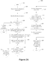
- FIG. 2A illustrates a process for a contention-based random access procedure performed by a UE using EC functionality, in accordance with various embodiments.
- the process 200 describes various processes described above in more detail.
- the process 200 may be performed by a UE, for example UE 102, used in EC mode operation in accordance with various embodiments.
- the UE may include one or more non-transitory computer-readable media having instructions, stored thereon, that when executed cause the UE to perform the process 200.
- the process may start at block 202.
- the UE 102 may receive random access procedure (RACH) configuration information from an eNB 104.
- RACH random access procedure
- the configuration information may be received by the UE 102 from the EC RA preamble assignment message 106, for example when the UE 102 is in idle mode and capable of EC mode.
- the configuration information may be broadcasted through SI by the eNB 104. In other embodiments, the configuration information may have been previously stored in the UE 102.
- the UE 102 may initialize RA related elements.
- the UE may initialize related elements similar to legacy RA mechanisms.
- new RA related parameters for EC mode UEs may be initialized.
- the RA related parameters may be, for example EC level, initial power level, or number of times to repeat a message.
- the UE 102 may make a determination related to whether criteria are met for the UE to start EC mode, or if a legacy RA procedure may be started.
- the UE 102 may decide which RA procedure mode may be used by information defined in specification, stored on the UE, and/or indicated to the UE through broadcast or dedicated messages.
- new rules, conditions, or criteria may be defined. For example, a rule may be defined that a UE having one or more unsuccessful completions under a legacy RA procedure may attempt to use EC RA procedure.
- threshold values may be used to trigger or determine when a UE should use an EC RA procedure. These threshold values could be defined based on some UE specific parameter, such as measured reference signal received power (RSRP), measured reference signal received quality (RSRQ), preamble transmission counter value or physical random access channel (PRACH) preamble transmission power.
- RSRP measured reference signal received power
- RSRQ measured reference signal received quality
- PRACH physical random access channel
- the determination may be based on the predefined category/capability specific information that is stored at the UE 102.
- UE Category X may be required to always use EC RA procedures, or alternatively UE Category X may be allowed to use EC RA procedure based on other criteria in addition to its category.
- the UE 102 may use the legacy RA procedure. The process 200 may then end at block 234.
- the UE 102 may use EC mode for the RA procedure and identify the starting EC level.
- the UE 102 may identify the EC level to use based on a stored value within the UE 102, or by receiving and/or decoding EC level information sent by the eNB 104 in the EC RA preamble assignment 106.
- the EC level may be important for a variety of reasons. For example, the RA related configuration may need to be updated based on the EC level.
- the maximum UL transmit power may be chosen directly with any EC level, or RA preambles and/or configurations may be based on the identified EC level.
- the EC level may also be associated with a specific number of message repetitions that are available to the UE 102 while attempting to communicate with the eNB.
- the RA procedure may use, for example, a number of repeated messages, with each subsequent repeat using an increased power level, or power ramp-up, when attempting to establish an RRC connection.
- Other aspects related to the RA message resource allocation information within the EC RA preamble assignment 106 may include details of frequency hopping, the group of sequences that may be used for the preamble transmission if the UE is in EC mode, and/or if different EC levels are identified by their preamble sequences.
- the UE 102 may send an RA preamble and corresponding copies of the RA preamble based on the identified EC level.
- the RA preamble may be repeatedly sent for a number of times based on the identified EC level.
- the RA preamble group and/or subgroup, RA preamble time resource (PRACH subframes), frequency resources, and the like may depend on the identified EC level, as well as the subframes where the UE 102 sends the multiple copies of the EC RA preamble to allow the network to combine the multiple EC RA preamble copies.
- the UE 102 may determine the RA-RNTI based on the identified EC level, RA preamble, and RA preamble time and frequency resource.
- the UE 102 may begin to receive and/or to combine resources to receive an EC RAR message 110.
- the resource location of the EC RAR message 110 may be known by the UE after determining release 13 RA-RNTI, through a release 13 enhanced physical downlink control channel (ePDCCH) addressed to a group of UEs that attempt to access with same EC level or EC RA preamble 108, or through a release 13 ePDCCH addressed to specific UE or based on pre-configured/pre-defined information that is pre-defined and/or broadcasted in an SI message.
- ePDCCH enhanced physical downlink control channel
- the EC RAR message 110 could be a release 13 RAR different for that EC level or could be UE specific or a new kind of EC RAR message 110 that may carry the random access response. This process might be done only once, or repeated several times if a release 13 EC RAR-window concept is also defined and/or extended, as described below.
- the UE 102 may determine whether the EC RAR message 110 addressed to the UE was successfully decoded within a window of time.
- the window of time may be the EC window value.
- the window of time may vary based on the EC level, for example it may be proportional to the EC level identified or may be based on the maximum number of preamble repetitions allowed for the EC level.
- the transmission counter may be incremented by one.
- the EC RAR message 110 may not have been successfully decoded because it may not have been sent by the eNB, or may have been sent but may not have contained the RAPID that the UE included in the EC RA preamble 108.
- the UE 102 may determine if the transmission counter is equal to the maximum transmission count for the current EC level. If the transmission counter is equal to the maximum transmission count for the current EC level, then at block 230 the UE 102 may determine that the EC RA procedure has unsuccessfully completed. In embodiments, this may occur if the maximum number of attempts is reached for the highest EC level. In embodiments, the UE may inform the RRC upper layers about the RA failure, and the upper layers may initiate the EC RA procedure again at a later time.
- the RA procedure may be initiated by changing the EC level, for example incrementing the EC level, to a level more suitable for when the UE is deeper within the enhanced coverage region of the cell such as deep within a building.
- the process 200 may end.
- the UE 102 may wait for the back-off time to expire for the EC level.
- the UE may try to send the EC RA preamble 108 again. For example, this may be done after applying preamble power ramping if specified or configured for EC.
- a transmission counter may be used to place a limit on the maximum number of PRACH preamble transmission trials for the current EC level.
- a transmission counter may determine when the UE may switch to another EC level, for example to a higher EC level which may allow for more message repetitions or a higher power level.
- the UE 102 may increment the transmission counter by 1, and the process 200 may proceed to block 212.
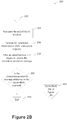
- FIG. 2B illustrates a process 250 for contention-based random access procedure performed by a UE using EC functionality, in accordance with various embodiments.
- the process 250 may be performed by a UE (e.g., UE 102) for EC mode operation in accordance with various embodiments.
- the UE may include one or more non-transitory computer-readable media having instructions, stored thereon, that when executed cause the UE to perform the process 250.
- the process 250 may continue from block 220 of Figure 2A .
- the UE 102 may wait until the end of the EC window. In embodiments, the UE may wait until the end of the EC window before it starts transmitting the EC Scheduled Transmission message 112. In embodiments, for any particular EC level identified, as described for example in block 212, that EC level may have an associated number of repetitions identifying the number of times the EC RAR message 110 has been sent. If the UE is able to decode the EC RAR message 110 earlier than the number of times the EC RAR message 110 has been sent, the UE may wait for the amount of time it may take the last EC RAR message 110 to be received. In embodiments, the UL allocation of the EC scheduled transmission 112 may be scheduled only after the last repetition of the EC RAR message 110 is sent by the eNB.
- the UE 102 may send a scheduled transmission, for example an RRC connection request, to the eNB.
- the UE 102 may, after an identified time, begin to receive the contention resolution message.
- the UE 102 may determine if the contention resolution message addressed to the UE has been successfully received.
- a process similar to the EC RA procedure, as described above, may be applied or extended if the RA procedure fails in contention resolution phase 114. In embodiments, this may occur if the EC scheduled transmission 112 was not correctly received at the eNB or if the EC scheduled transmission 112 from the given UE collided with another EC scheduled transmission 112 and only the other UE's EC scheduled transmission 112 was detected. For the latter case, the given UE may receive the EC contention resolution message 114 from the eNB but may determine that it was not addressed to that specific UE.
- a concept similar to legacy mac-ContentionResolutionTimer may be applied if EC contention resolution 114 is not received while using EC mode.
- the value of this timer may scale or may be updated based on how long the EC repetitions of the scheduled transmission 112 are expected to take. This may occur when the EC scheduled transmission 112 was not correctly received by the eNB or the eNB received and responded but the EC contention resolution 114 was not received successfully at the UE.
- the process 250 may end.
- the process may proceed to block 262 which then may return the process to block 208 of Figure 2A .
- the UE may apply an analogous procedure to resend the RA preamble with incrementing or re-initializing the preamble transmission counter. For the option of re-initialization of the preamble transmission counter, the UE may restart the RA process again as in the case of legacy operation.
- the process may allow the UE to switch to legacy procedure instead of EC procedure, or vice versa. Additionally, the updated network conditions may tell the UE to start from different EC level.
- the use of the contention-based RA procedure for EC mode by a UE in RRC IDLE may be shown, for example initiating an RRC connection.
- the contention-based RA procedure for EC mode may also be used by a UE in RRC_CONNECTED.
- legacy names may be used for the new release 13 EC RA parameters and embodied procedures. However, this should not be restricted to these names, as some of the names may refer to same parameters as used in the legacy RA procedure or may also refer to completely new and different parameters that get defined to fulfil the same functionality explained herein.
- the UE may select the RA resources differently depending on whether the UE uses the legacy RA procedure or the EC RA procedure.
- different values of the legacy RA parameters or even different or new parameters may be defined for EC mode or for each EC level.
- back-off time which may be a parameter involved in the RA procedure, may have one or more different values per EC level or different parameters might be defined for each EC level.
- the PREAMBLE_TRANS_MAX value may be updated or a new parameter may be defined to trigger when the legacy RA procedure may pass to the EC RA procedure.
- power ramping for preamble transmission may not be considered when EC mode is used in RA procedure, as the UE may use maximum transmit power in challenging locations with poor coverage.
- the new release 13 criteria or conditions may be defined in the specification or may be broadcasted for the UE to know which parameters or values should be used for EC RA procedure or for a specific EC RA level.
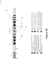
- Figures 3A , 3B , and 3C are diagrams illustrating example frame structures for implementing RAR opportunities within an EC RAR window that may be used by a UE when receiving an EC RAR, in accordance with various embodiments.
- diagram 300 shows one implementation of an EC RAR window 304 within a sequence of frames 302.
- the EC RAR window 304 may start k subframes after the EC RA preamble transmission 108 is supposed to finish.
- k may be defined to a value of 3, for example, to accommodate devices operating in accordance with legacy long term evolution (LTE) RA procedures, or it may be a greater value, for example, in order to account for increased processing requirements for the eNB to support a reduced bandwidth UEs and EC mode.
- LTE long term evolution
- the EC RAR window 304 may contain one or more EC RAR opportunities 306.
- the number of EC RAR opportunities 306a, 306b, 306c within the EC RAR window 304 may be defined in the specification or may be broadcasted as part of the EC RA Preamble assignment 106.
- the first EC RAR 306a may start at the same sub-frame as the EC RAR window 304.
- the length of the EC RAR opportunity 306a may vary. For example, the length may depend on the number of repetitions required for the EC level, or on how many of the subframes in the EC RAR opportunity 306a carry an actual EC RAR message 110.
- Diagram 300 shows an example where all of the subframes in the EC RAR opportunities 306a, 306b, 306c carry an EC RAR message 110.
- the first transmission of the EC RA preamble 106 for a specific EC level may occur within multiple RA preamble sub frames 302a.
- a specific EC RA preamble 302a1 may be sent in specific time and frequencies, (i.e. resources) for the eNB to know that the UE is using a certain EC level.
- the EC RA preamble may also identify whether this UE is release 13 LC.
- subsequent transmissions of the EC RA preamble 302a2 may use the EC RACH process for a specific EC level. For example, the subsequent transmissions of the EC RA preamble 302a2 may be in different subframes (not shown).
- the UE may wait k subframes before starting the EC RAR window 304.
- the RAR opportunities 306 may have the same number of frames as the EC RAR window.
- UE may combine the EC RAR related resources of each sub-frame within the first EC RAR opportunity 306a so that the EC RAR message 110 may be decoded.
- the UE may then look for a RA-RNTI and, if the RA-RNTI is found, the UE may then look for the RAR message.
- the second EC RAR opportunity 306b of the EC RAR window 306 may be identified. In embodiments, this may be in response to subsequent transmissions of the EC RAR message 110, for example a response to one of the EC RA preamble 108 repetitions, where the number of repetitions may be identified based on EC level.
- UE 102 using a certain EC level may require x 310 and y 308 EC total repetitions for the uplink and downlink directions respectively, where x 310 or y 308 may have the same or different values for uplink and downlink. In these embodiments, the EC repetitions are consecutive.
- the UE may wait z 312 subframes before sending an EC scheduled transmission 112 in the UL in accordance with the allocated grant from the decoded EC RAR message 110.
- the other EC RAR opportunity 306c may be ignored because the UE has already successfully decoded the RAR message from the eNB.
- EC RAR window 304 may be formed in a number of ways.
- the EC RAR window 304 may be formed by EC RAR opportunities 306a, 306b, 306c of one specific EC level.
- UEs that may be checking that EC RAR window would have the same EC level requirement.
- the network might have a different EC RAR window 304 region for each EC level, which may have different locations in time, frequency and/or number of EC required repetitions.
- EC RAR opportunities 306a, 306b, 306c may differ based on different EC levels.
- the network may indicate or the 3GPP LTE specification may define which EC level may correspond to each EC RAR opportunity (not shown).
- all opportunities of the same EC level may be located consecutively or they may be alternated.
- FIG. 3B diagram 325 shows an example of an EC RAR window where not all subframes in the EC RAR opportunities 306a, 306b, 306c carry an EC RAR message 110.
- UE 102 may be using an EC level that may require x 316 and y 314 EC total repetitions for each downlink and uplink direction respectively, where x 316 and y 314 may have the same or different values. In this example, EC repetitions are not in consecutive subframes.
- diagram 350 shows embodiments where the length of the EC RAR opportunities 306a, 306b, 306c may also vary if, in addition to the EC RAR message 110, an RA control indicator (EC RA-RNTI) is received.
- an RA control indicator EC RA-RNTI
- the RA control identifier 318a is prepended to the RAR message 318b.
- the EC repetitions are consecutive.
- the RA control identifier 318a area may be used for other RAR messaging.
- the additional message added to the RAR opportunity window may be due to repetitions of the Physical Downlink Control Channel (PDCCH) for MTC that may be based on release 13 enhanced physical downlink control channel (ePDCCH).
- the downlink control information (DCI) carried by this PDCCH, with its cyclic redundancy check CRC scrambled with the EC RA-RNTI, may schedule the transmission of the RAR message using cross-sub-frame scheduling.
- some EC RA parameters such as EC RA preamble, EC RAR window, and EC RAR opportunity, may be defined differently depending on the EC level, for example 5 decibels (dB) EC vs 10dB EC. Examples may include different starting times, different allocation of frequency resources, or number of EC repetitions required.
- dB decibels
- the number of EC repetitions for each RA message sent between the UE and eNB in EC mode may be the same or may differ for each message. In embodiments, the number of repetitions may differ, based on the number of repetitions of one or more of the previous messages sent between the UE and eNB in EC mode.
- the number of repetitions for the EC RAR message 110 may be a function of the number of repetitions for EC RA preamble 108, with an adjustment based on the difference between the downlink and uplink timing.
- the number of repetitions for the EC scheduled transmission 112 may be indicated in the EC RAR message 110 or may be otherwise specified.
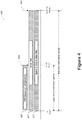
- Figure 4 is a diagram illustrating frame structures for implementing a different modification period for the SI addressed to a UE in EC mode, in accordance with various embodiments.
- Diagram 400 shows, in embodiments, an rSIB1 which may be used for release 13 low complexity and delay tolerant UEs, such as release 13 LC UE and release 13 UEs capable of using EC mode.
- this rSIB1 that contains cell specific configuration information may be changed same as for legacy SIBs at instances other than that of the N + k ⁇ M frame 404.
- implementing an rSIB1 may have the advantage of lessening the impact and restrictions on legacy network behavior.
- a first rSIB, rSIB 1 406, may have the same modification period as legacy SIBs and the rSIB 1 406 also may be updated at the N+M frame 408.
- other rSIBs 410 which do not contain cell specific configuration information may be changed less frequently, for example less often with longer modification periods.
- rSIB1 406 and other SIBs 412 may have the same modification period and may be updated at the end of the N + k ⁇ M frame 404.
- FIG. 5 illustrates a simplified block diagram of UE 102 of Fig. 1 in accordance with various embodiments of the disclosure.
- UE 102 includes a processor 510, radio frequency (RF) circuitry 540 and a memory 520.
- the processor 510 may include one or more single-core or multi-core processors, and may include any combination of general-purpose processors and dedicated processors (e.g. graphics processors, application processors, baseband processors, etc.).
- the processor 510 (and in particular, a baseband chipset of the processor 510) may include configuration logic.
- the configuration logic may be operable to identify an initial EC level that is to be used during a contention-based RA procedure, the EC level having at least an associated power level, window of time, and number of send attempts.
- the configuration logic may be operable to send a first message to a radio access network (RAN) based on the identified EC level.
- the configuration logic may be operable to determine whether a second message from the RAN in response to the first message is received within the window of time.
- the configuration logic may be operable to, if the second message is received from the eNB within the window of time, decode the received second message.
- the configuration logic may be operable to, if the second message is not received from the eNB within the window of time, re-send the first message to the RAN and track a number of times the first message has been sent using a transmission counter having a numerical value; and output an indication that the EC RA procedure did not complete successfully based on determination of a whether the second message is received within a window of time and a comparison of the transmission counter to a transmission threshold value.
- the RF circuitry 540 may be coupled to the processor 510, for example via a bus 530, and may be used to transmit or receive data.
- the memory 520 may include one or more non-transitory, computer-readable media having instructions stored thereon, and the instructions when executed by the processor 510 may cause UE 102 to perform the operations described above in connection with the processor 510.
- this is only illustrative rather than limiting; those of ordinary skill in the art will appreciate alternative implementations in software, hardware, firmware, or any combination thereof.
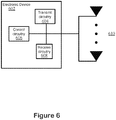
- Figure 6 illustrates electronic device circuitry 602 that may be eNB circuitry, UE circuitry, or some other type of circuitry in accordance with various embodiments.
- the electronic device circuitry 602 may be, or may be incorporated into or otherwise a part of, an eNB, a UE, or some other type of electronic device.
- the electronic device circuitry 602 may include radio transmit circuitry and receive circuitry coupled to control circuitry 606.
- the transmit 604 and/or receive circuitry 608 may be elements or modules of transceiver circuitry, as shown.
- the electronic device circuitry 602 may be coupled with one or more plurality of antenna elements of one or more antennas 610.
- the electronic device circuitry and/or the components of the electronic device circuitry may be configured to perform operations similar to those described elsewhere in this disclosure.
- the UE may be capable of operation in accordance with EC mode.
- the control circuitry 606 may be to identify the EC mode.
- the control circuitry 606 may be further to operate in accordance with the EC mode.
- the transmit 604 and/or receive circuitry 608 may be to send and/or receive one or more signals or transmissions in accordance with the EC mode.
- the electronic device circuitry 602 is an eNB or is part of or otherwise incorporated into an eNB the electronic device may be capable of operation of different modification periods for transmission and update of SI.
- the control circuitry 606 may be to identify a modification period from a plurality of modification periods.
- the transmit circuitry 604 may be to transmit a transmission and/or update of SI in accordance with the identified modification period.
- circuitry may refer to, be part of, or include an Application Specific Integrated Circuit (ASIC), an electronic circuit, a processor (shared, dedicated, or group), and/or memory (shared, dedicated, or group) that execute one or more software or firmware programs, a combinational logic circuit, and/or other suitable hardware components that provide the described functionality.
- ASIC Application Specific Integrated Circuit
- the electronic device circuitry 602 may be implemented in, or functions associated with the circuitry may be implemented by, one or more software or firmware modules.
- FIG. 7 illustrates, for one embodiment, an example system 702 comprising RF circuitry 704, baseband circuitry 706, application circuitry 708, memory/storage 710, display 712, camera 714, sensor 716, and input/output (I/O) interface 718, coupled with each other at least as shown.
- RF circuitry 704 comprising RF circuitry 704, baseband circuitry 706, application circuitry 708, memory/storage 710, display 712, camera 714, sensor 716, and input/output (I/O) interface 718, coupled with each other at least as shown.
- I/O input/output
- the application circuitry 708 may include circuitry such as, but not limited to, one or more single-core or multi-core processors.
- the processor(s) may include any combination of general-purpose processors and dedicated processors (e.g., graphics processors, application processors, etc.).
- the processors may be coupled with memory/storage and configured to execute instructions stored in the memory/storage to enable various applications and/or operating systems running on the system.
- the baseband circuitry 706 may include circuitry such as, but not limited to, one or more single-core or multi-core processors.
- the processor(s) may include a baseband processor.
- the baseband circuitry 706 may handle various radio control functions that enables communication with one or more radio networks via the RF circuitry.
- the radio control functions may include, but are not limited to, signal modulation, encoding, decoding, radio frequency shifting, etc.
- the baseband circuitry 706 may provide for communication compatible with one or more radio technologies.
- the baseband circuitry 706 may support communication with an evolved universal terrestrial radio access network (EUTRAN) and/or other wireless metropolitan area networks (WMAN), a wireless local area network (WLAN), a wireless personal area network (WPAN).
- EUTRAN evolved universal terrestrial radio access network
- WMAN wireless metropolitan area networks
- WLAN wireless local area network
- WPAN wireless personal area network
- multi-mode baseband circuitry Embodiments in which the baseband circuitry is configured to support radio communications of more than one wireless protocol.
- baseband circuitry 706 may include circuitry to operate with signals that are not strictly considered as being in a baseband frequency.
- baseband circuitry 706 may include circuitry to operate with signals having an intermediate frequency, which is between a baseband frequency and a radio frequency.
- RF circuitry 704 may enable communication with wireless networks using modulated electromagnetic radiation through a non-solid medium.
- the RF circuitry 704 may include switches, filters, amplifiers, etc. to facilitate the communication with the wireless network.
- RF circuitry 704 may include circuitry to operate with signals that are not strictly considered as being in a radio frequency.
- RF circuitry 704 may include circuitry to operate with signals having an intermediate frequency, which is between a baseband frequency and a radio frequency.
- transmit circuitry 604, control circuitry 606, and/or receive circuitry 608 discussed or described herein may be embodied in whole or in part in one or more of the RF circuitry, the baseband circuitry, and/or the application circuitry.
- the term "circuitry" may refer to, be part of, or include an ASIC, an electronic circuit, a processor (shared, dedicated, or group), and/or memory (shared, dedicated, or group) that execute one or more software or firmware programs, a combinational logic circuit, and/or other suitable hardware components that provide the described functionality.
- the electronic device circuitry may be implemented in, or functions associated with the circuitry may be implemented by, one or more software or firmware modules.
- some or all of the constituent components of the baseband circuitry, the application circuitry, and/or the memory/storage may be implemented together on a system on a chip (SOC).
- SOC system on a chip
- Memory/storage 710 may be used to load and store data and/or instructions, for example, for system.
- Memory/storage 710 for one embodiment may include any combination of suitable volatile memory (e.g., dynamic random access memory (DRAM)) and/or non-volatile memory (e.g., Flash memory).
- suitable volatile memory e.g., dynamic random access memory (DRAM)
- non-volatile memory e.g., Flash memory
- the I/O interface 718 may include one or more user interfaces designed to enable user interaction with the system and/or peripheral component interfaces designed to enable peripheral component interaction with the system.
- User interfaces may include, but are not limited to a physical keyboard or keypad, a touchpad, a speaker, a microphone, etc.
- Peripheral component interfaces may include, but are not limited to, a non-volatile memory port, a universal serial bus (USB) port, an audio jack, and a power supply interface.
- USB universal serial bus
- sensor 716 may include one or more sensing devices to determine environmental conditions and/or location information related to the system.
- the sensors 716 may include, but are not limited to, a gyro sensor, an accelerometer, a proximity sensor, an ambient light sensor, and a positioning unit.
- the positioning unit may also be part of, or interact with, the baseband circuitry 706a and/or RF circuitry 704 to communicate with components of a positioning network, e.g., a global positioning system (GPS) satellite.
- GPS global positioning system
- the display 712 may include a liquid crystal display, a touch screen display, and the like.
- system 702 may be a mobile computing device such as, but not limited to, a laptop computing device, a tablet computing device, a netbook, an ultrabook, a smartphone, etc.
- system may have more or less components, and/or different architectures.
- the system 702 may be a mobile computing device such as, but not limited to, a laptop computing device, a tablet computing device, a netbook, an ultrabook, a smartphone, etc.
- system may have more or less components, and/or different architectures.
- the RF circuitry 704 and/or the baseband circuitry 706 may be embodied in communication circuitry (not shown).
- the communication circuitry may include circuitry such as, but not limited to, one or more single-core or multi-core processors and logic circuits to provide signal processing techniques, for example, encoding, modulation, filtering, converting, amplifying, etc., suitable to the appropriate communication interface over which communications will take place.
- the communication circuitry may communicate over wireline, optical, or wireless communication mediums.
- the communication circuitry may include the RF circuitry and/or baseband circuitry to provide for communication compatible with one or more radio technologies.
- the communication circuitry may support communication with an evolved universal terrestrial radio access network (EUTRAN) and/or other wireless metropolitan area networks (WMAN), a wireless local area network (WLAN), a wireless personal area network (WPAN).
- EUTRAN evolved universal terrestrial radio access network
- WMAN wireless metropolitan area networks
- WLAN wireless local area network
- WPAN wireless personal area network
- Embodiments of the technology herein may be described as related to the 3GPP long term evolution (LTE) or LTE-advanced (LTE-A) standards.
- LTE long term evolution
- LTE-A LTE-advanced
- terms or entities such as eNB, mobility management entity (MME), UE, etc. may be used that may be viewed as LTE-related terms or entities.
- the technology may be used in or related to other wireless technologies such as the Institute of Electrical and Electronic Engineers (IEEE) 802.16 wireless technology (WiMax), IEEE 802.11 wireless technology (WiFi), various other wireless technologies such as global system for mobile communications (GSM), enhanced data rates for GSM evolution (EDGE), GSM EDGE radio access network (GERAN), universal mobile telecommunications system (UMTS), UMTS terrestrial radio access network (UTRAN), or other 2G, 3G, 4G, 5G, etc. technologies either already developed or to be developed.
- LTE-related terms such as eNB, MME, UE, etc.
- one or more entities or components may be used that may be considered to be equivalent or approximately equivalent to one or more of the LTE-based terms or entities.
- Embodiments of the disclosure also relate to an apparatus for performing the operations herein.
- a computer program is stored in a non-transitory computer-readable medium.
- a machine-readable medium includes any mechanism for storing information in a form readable by a machine (e.g., a computer).
- a machine-readable (e.g., computer-readable) medium includes a machine- (e.g., a computer-) readable storage medium (e.g., read only memory (ROM), random access memory (RAM), magnetic disk storage media, optical storage media, flash memory devices).
- processing logic that comprises hardware (e.g., circuitry, dedicated logic, etc.), software (e.g., embodied on a non-transitory computer-readable medium), or a combination of both.
- processing logic comprises hardware (e.g., circuitry, dedicated logic, etc.), software (e.g., embodied on a non-transitory computer-readable medium), or a combination of both.
- Embodiments of the present disclosure are not described with reference to any particular programming language. It will be appreciated that a variety of programming languages can be used to implement the teachings of embodiments of the disclosure as described herein. In the foregoing Specification, embodiments of the disclosure have been described with reference to specific exemplary embodiments thereof. The Specification and drawings are to be regarded in an illustrative sense rather than a restrictive sense.
Description
- Embodiments of the present disclosure relate generally to the field of wireless communications, and more particularly, to computer devices operable to implement a contention-based random access procedure.
- The background description provided herein is for the purpose of generally presenting the context of the disclosure.
- Machine-type communication (MTC) technology may enable ubiquitous computing environments as progress moves towards the concept of the "Internet of Things" (IoT). Potential MTC-based applications include smart metering, healthcare monitoring, remote security surveillance, intelligent transportation systems, individual item inventory control, and so forth. These services and applications may stimulate the design and development of a new type of MTC device that may be seamlessly integrated into current and future generation mobile broadband networks.
- Existing mobile broadband networks are designed to optimize performance mainly for human-type communications. Therefore, existing networks may not be adapted or optimized for MTC-related requirements. MTC-specific designs may be explored, for example, by the Third Generation Partnership Project (3GPP). Future 3GPP specifications may support different network design, which may improve MTC.
- For example, in 3GPP release 12 a new physical layer UE category, referred to as
Category 0, was introduced into the E-UTRA specifications. This UE category has lower capabilities, for example in terms of peak data rate capability and in terms of transmission and reception performance due to support of only a single antenna, than the previouslowest Category 1. One of the aims for introducingCategory 0 is to enable lower cost user equipment (UE) for MTC applications. - In 3GPP release 13 a new physical layer UE category (Category X) is being introduced having even lower capability and lower cost, compared to
Category 0 added in release 12. In addition, an Enhanced Coverage (EC) feature is being introduced to increase the link budget by up to 15 decibels (dB). The EC feature will enable the EUTRAN to communicate with UEs that are located in challenging locations where currently coverage cannot be provided or is difficult to provide to UEs, for example deep inside a building, in a basement, inside a pallet of goods and the like. Category X and EC are targeted to UEs primarily used for MTC applications. Category X and EC may be independently implemented and a UE may support either one or both. - Document
WO 2015/021318 A2 refers to coverage enhancements of low cost machine type communication (LC-MTC) devices in uplink/downlink decoupled scenario. This document discloses systems, methods, and instrumentalities to describe cell selection in LC-MTC devices. An LTC-MC device may measure a plurality of downlink signals from a plurality of cells. The LTC-MC may detect a channel condition, e.g., by determining a cell with better uplink coverage than a downlink cell. The detection of the channel condition may include measuring an uplink pathloss. The LTC-MC may report the channel condition as a decoupled channel condition, e.g., when an uplink cell is identified with uplink coverage better than the downlink cell. The channel condition may be reported, e.g., via a set of Physical Random Access Channel (PRACH) preambles. The set of PRACH preambles may be predefined. The channel condition may be reported via a higher layer signaling. - The object of the present application is solved by the independent claims. Advantageous embodiments are described by the dependent claims.
- The embodiments of the disclosure are illustrated by way of example and not by way of limitation in the figures of the accompanying drawings in which like references indicate similar elements. It should be noted that references to "an" or "one" embodiment of the disclosure are not necessarily to the same embodiment, and they may mean at least one. It should also be noted that references to an "example" are references to non-limiting examples, unless otherwise stated.
-
Figure 1 illustrates a communication message flow between an evolved Node B (eNB) and a user equipment (UE) using EC mode, in accordance with various embodiments. -
Figure 2A illustrates a process for a contention-based random access procedure performed by a UE using EC functionality, in accordance with various embodiments. -
Figure 2B illustrates a process for contention-based random access procedure performed by a UE using EC functionality, in accordance with various embodiments. -
Figures 3A ,3B , and3C are diagrams illustrating frame structures that may be used for implementing random access response (RAR) opportunities within an EC RAR window that may be used by a UE and an eNB, in accordance with various embodiments. -
Figure 4 is a diagram illustrating frame structures for implementing a different modification period for the system information (SI) addressed to a UE in EC mode, in accordance with various embodiments. -
Figure 5 is a block diagram illustrating a computing device adapted to operate in a wireless communication network in EC mode, in accordance with various embodiments. -
Figure 6 illustrates electronic device circuitry that may be eNB circuitry, UE circuitry, or some other type of circuitry in accordance with various embodiments. -
Figure 7 illustrates, for one embodiment, an example system comprising radio frequency (RF) circuitry, baseband circuitry, application circuitry, memory/storage, display, camera, sensor, and input/output (I/O) interface, coupled with each other at least as shown. - In the following detailed description, reference is made to the accompanying drawings, which form a part hereof wherein like numerals designate like parts throughout, and in which is shown by way of illustration embodiments that may be practiced. It is to be understood that other embodiments may be utilized and structural or logical changes may be made without departing from the scope of the present disclosure. Therefore, the following detailed description is not to be taken in a limiting sense, and the scope of embodiments is defined by the appended claims and their equivalents.
- Various operations may be described as multiple discrete actions or operations in turn, in a manner that is most helpful in understanding the claimed subject matter. However, the order of description should not be construed as to imply that these operations are necessarily order dependent. In particular, these operations may not be performed in the order of presentation. Operations described may be performed in a different order than the described embodiment. Various additional operations may be performed and/or described operations may be omitted in additional embodiments.
- The description may use the phrases "in an embodiment," or "in embodiments," which may each refer to one or more of the same or different embodiments. Furthermore, the terms "comprising," "including," "having," and the like, as used with respect to embodiments of the present disclosure, are synonymous.
- As used herein, the terms "module" and/or "logic" may refer to, be part of, or include an Application Specific Integrated Circuit (ASIC), an electronic circuit, a processor (shared, dedicated, or group), and/or memory (shared, dedicated, or group) that execute one or more software or firmware programs, a combinational logic circuit, and/or other suitable hardware components that provide the described functionality.
- As used herein, the term "circuitry" may refer to, be part of, or include an ASIC, an electronic circuit, a processor (shared, dedicated, or group), and/or memory (shared, dedicated, or group) that execute one or more software or firmware programs, a combinational logic circuit, and/or other suitable hardware components that provide the described functionality. In some embodiments, circuitry may be implemented in, or functions associated with the circuitry may be implemented by, one or more software or firmware modules.
- In embodiments, the disclosure herein may refer to processes, apparatus, and/or techniques for enhancing machine-to-machine communication related to the random access procedure process between an evolved NodeB (eNB) and a user equipment (UE) running in EC mode. These embodiments may include associating multiple levels with an EC mode, and for each level identifying a number of repetitions of messages sent between the UE and the eNB, as well as different power levels that may be used by the UE to attempt communication with an eNB depending upon the EC mode level. In addition, embodiments may include adding additional random access response (RAR) opportunity windows to receive and decode multiple RAR's that may be sent in response to multiple random access preambles. Also, embodiments may include support for a different modification period for the SI messages addressed to release-13 LC UEs and release-13 EC UEs.
- In embodiments, UEs using this solution may operate in reduced bandwidth regions, such as 1.4MHz in release-13, or may operate in more narrowband regions, such as 200kHz. The eNB may also operate at higher system bandwidth.
-
Figure 1 illustrates a communication message flow between a UE and an eNB using EC mode, in accordance with various embodiments. Diagram 100 may include a UE 102 and wireless communication with an access node such as eNB 104. TheUE 102 and theeNB 104 may be in communication to establish a radio resource control (RRC) connection using a contention-based RA procedure in EC mode. - An EC random access (RA)
preamble assignment 106 may be sent from theeNB 104 to theUE 102. In embodiments, theRA preamble assignment 106 may include random access configuration information related to release 13 LC (low cost) UEs andrelease 13 EC mode UEs and may be broadcasted through system information (SI), or may be pre-defined in theUE 102. Random access configuration information, in embodiments, may include an EC level to be used by theUE 102, a value indicating the number of additional repetitions of each EC mode message allowed for that EC level, and/or one or more power levels to be used for repeated communication attempts. - An
EC RA preamble 108 may be sent from theUE 102 to theeNB 104. AnEC RAR message 110 may be sent by theeNB 104 in response to theEC RA preamble 108, within an EC RAR window which, in embodiments, may be received in a plurality of contiguous subframes. The contents of theEC RA preamble 108 may determine the random access radio network temporary identifier (RA-RNTI) that theUE 102 may look for in EC RA response (EC RAR)message 110 subframes received from theeNB 104. - In embodiments, the
eNB 104 may have flexibility regarding the location within the EC RAR window theEC RAR message 110 is transmitted. In embodiments, theUE 102 may search for a RA-RNTI on a physical downlink control channel (PDCCH). In embodiments, the PDCCH received by UE in EC mode may be different from legacy PDCCHs. For example, the legacy PDCCH may be sent within the whole system bandwidth in the first OFDMA symbols of a subframe. However, for EC mode, the PDCCH may be sent in reduced bandwidth region within the legacy PDCCH. - The
EC RAR message 110 may include a random access preamble identifier (RAPID) and a temporary cell radio network temporary identifier (T-CRNTI). - An EC scheduled
transmission 112 may be sent by theUE 102 to theeNB 104. In embodiments, if theEC RAR message 110 is received in sub-frame n, theUE 102 may send a scheduled data item via physical uplink shared channel (PUSCH) in subframe n+k, k≥6. TheUE 102 may further apply Hybrid Automatic Repeat Request (HARQ) with maxHARQ-Msg3Tx. TheUE 102 may also start a timer such as timer T300 for RRC connection request and monitor for T-CRNTI on PDCCH. Finally, theUE 102 may start mac-ContentionResolutionTimer. In embodiments, the mac-ContentionResolutionTimer may be restarted at each HARQ retransmission. - An EC
contention resolution message 114 may be sent by theeNB 104 to theUE 102. In embodiments, the T-CRNTI is used in PDCCH and HARQ may be applied for the associated PDSCH byeNB 104. In embodiments, theUE 102 may send HARQ feedback only on PUCCH when it detects itsown UE 102 identity as provided in the EC scheduledtransmission 112. In embodiments, the ECcontention resolution message 114 may be received byUE 102 while mac-ContentionResolutionTimer is running. If ECcontention resolution message 114 is received successfully, theUE 102 Contention Resolution Identity MAC CE may contain the UL common control channel (CCCH) service data unit (SDU) of the ECcontention resolution message 114. - In embodiments, advantages of the communications in EC mode described above may include a greater likelihood of an RRC connection establishment between a UE and eNB, particularly when the UE is implemented as part of IoT. Advantages may also include providing a greater likelihood of an RRC connection establishment while using less power, for example by ramping up power used by the UE to the point where the RA procedure is able to establish an RRC connection, where the UE does not have to continuously operate a maximum power. In addition, through supporting repeated attempts for transmissions between the UE and the eNB during the RA procedure, the likelihood of an RRC connection establishment is greatly increased.
-
Figure 2A illustrates a process for a contention-based random access procedure performed by a UE using EC functionality, in accordance with various embodiments. Theprocess 200 describes various processes described above in more detail. Theprocess 200 may be performed by a UE, forexample UE 102, used in EC mode operation in accordance with various embodiments. In some embodiments, the UE may include one or more non-transitory computer-readable media having instructions, stored thereon, that when executed cause the UE to perform theprocess 200. - The process may start at
block 202. - At
block 204, theUE 102 may receive random access procedure (RACH) configuration information from aneNB 104. In embodiments, the configuration information may be received by theUE 102 from the EC RApreamble assignment message 106, for example when theUE 102 is in idle mode and capable of EC mode. The configuration information may be broadcasted through SI by theeNB 104. In other embodiments, the configuration information may have been previously stored in theUE 102. - At
block 206, theUE 102 may initialize RA related elements. In embodiments, the UE may initialize related elements similar to legacy RA mechanisms. In embodiments, new RA related parameters for EC mode UEs may be initialized. The RA related parameters may be, for example EC level, initial power level, or number of times to repeat a message. - At
block 208, theUE 102 may make a determination related to whether criteria are met for the UE to start EC mode, or if a legacy RA procedure may be started. In embodiments, theUE 102 may decide which RA procedure mode may be used by information defined in specification, stored on the UE, and/or indicated to the UE through broadcast or dedicated messages. In examples, new rules, conditions, or criteria may be defined. For example, a rule may be defined that a UE having one or more unsuccessful completions under a legacy RA procedure may attempt to use EC RA procedure. - In other non-limiting examples, threshold values may be used to trigger or determine when a UE should use an EC RA procedure. These threshold values could be defined based on some UE specific parameter, such as measured reference signal received power (RSRP), measured reference signal received quality (RSRQ), preamble transmission counter value or physical random access channel
(PRACH) preamble transmission power. - In other non-limiting examples, the determination may be based on the predefined category/capability specific information that is stored at the
UE 102. For example, UE Category X may be required to always use EC RA procedures, or alternatively UE Category X may be allowed to use EC RA procedure based on other criteria in addition to its category. - If the criteria are not met to start EC mode, then at
block 210 theUE 102 may use the legacy RA procedure. Theprocess 200 may then end atblock 234. - Otherwise, if the criteria are met to start EC mode, then at
block 212 theUE 102 may use EC mode for the RA procedure and identify the starting EC level. In embodiments, theUE 102 may identify the EC level to use based on a stored value within theUE 102, or by receiving and/or decoding EC level information sent by theeNB 104 in the ECRA preamble assignment 106. The EC level may be important for a variety of reasons. For example, the RA related configuration may need to be updated based on the EC level. The maximum UL transmit power may be chosen directly with any EC level, or RA preambles and/or configurations may be based on the identified EC level. The EC level may also be associated with a specific number of message repetitions that are available to theUE 102 while attempting to communicate with the eNB. As a result, the RA procedure may use, for example, a number of repeated messages, with each subsequent repeat using an increased power level, or power ramp-up, when attempting to establish an RRC connection. Other aspects related to the RA message resource allocation information within the ECRA preamble assignment 106 may include details of frequency hopping, the group of sequences that may be used for the preamble transmission if the UE is in EC mode, and/or if different EC levels are identified by their preamble sequences. - At
block 214, theUE 102 may send an RA preamble and corresponding copies of the RA preamble based on the identified EC level. In embodiments, the RA preamble may be repeatedly sent for a number of times based on the identified EC level. In embodiments, the RA preamble group and/or subgroup, RA preamble time resource (PRACH subframes), frequency resources, and the like may depend on the identified EC level, as well as the subframes where theUE 102 sends the multiple copies of the EC RA preamble to allow the network to combine the multiple EC RA preamble copies. In embodiments, there may be a maximum of n preamble copies sent, n depending on the identified EC level. In embodiments, theUE 102 may determine the RA-RNTI based on the identified EC level, RA preamble, and RA preamble time and frequency resource. - At
block 216, theUE 102 may begin to receive and/or to combine resources to receive anEC RAR message 110. In embodiments, the resource location of theEC RAR message 110 may be known by the UE after determiningrelease 13 RA-RNTI, through arelease 13 enhanced physical downlink control channel (ePDCCH) addressed to a group of UEs that attempt to access with same EC level orEC RA preamble 108, or through arelease 13 ePDCCH addressed to specific UE or based on pre-configured/pre-defined information that is pre-defined and/or broadcasted in an SI message. In addition, theEC RAR message 110 could be arelease 13 RAR different for that EC level or could be UE specific or a new kind ofEC RAR message 110 that may carry the random access response. This process might be done only once, or repeated several times if arelease 13 EC RAR-window concept is also defined and/or extended, as described below. - At
block 218, theUE 102 may determine whether theEC RAR message 110 addressed to the UE was successfully decoded within a window of time. In embodiments, the window of time may be the EC window value. In embodiments, the window of time may vary based on the EC level, for example it may be proportional to the EC level identified or may be based on the maximum number of preamble repetitions allowed for the EC level. - If the
EC RAR message 110 was successfully decoded within a window of time, then atblock 220 the process goes to block 252 ofFigure 2B . - Otherwise, if the
EC RAR message 110 was not successfully decoded within a window of time, then atblock 222 the transmission counter may be incremented by one. In embodiments, theEC RAR message 110 may not have been successfully decoded because it may not have been sent by the eNB, or may have been sent but may not have contained the RAPID that the UE included in theEC RA preamble 108. - At
block 224, theUE 102 may determine if the transmission counter is equal to the maximum transmission count for the current EC level. If the transmission counter is equal to the maximum transmission count for the current EC level, then atblock 230 theUE 102 may determine that the EC RA procedure has unsuccessfully completed. In embodiments, this may occur if the maximum number of attempts is reached for the highest EC level. In embodiments, the UE may inform the RRC upper layers about the RA failure, and the upper layers may initiate the EC RA procedure again at a later time. Based on the previous RA failure, the RA procedure may be initiated by changing the EC level, for example incrementing the EC level, to a level more suitable for when the UE is deeper within the enhanced coverage region of the cell such as deep within a building. Atblock 232, theprocess 200 may end. - Otherwise, if the transmission counter is not equal to the maximum transmission count for the current EC level, then at
block 226 theUE 102 may wait for the back-off time to expire for the EC level. In embodiments, the UE may try to send theEC RA preamble 108 again. For example, this may be done after applying preamble power ramping if specified or configured for EC. In embodiments, a transmission counter may be used to place a limit on the maximum number of PRACH preamble transmission trials for the current EC level. In embodiments, a transmission counter may determine when the UE may switch to another EC level, for example to a higher EC level which may allow for more message repetitions or a higher power level. - At
block 228, theUE 102 may increment the transmission counter by 1, and theprocess 200 may proceed to block 212. -
Figure 2B illustrates aprocess 250 for contention-based random access procedure performed by a UE using EC functionality, in accordance with various embodiments. Theprocess 250 may be performed by a UE (e.g., UE 102) for EC mode operation in accordance with various embodiments. In some embodiments, the UE may include one or more non-transitory computer-readable media having instructions, stored thereon, that when executed cause the UE to perform theprocess 250. - At
block 252, theprocess 250 may continue fromblock 220 ofFigure 2A . - At
block 254, theUE 102 may wait until the end of the EC window. In embodiments, the UE may wait until the end of the EC window before it starts transmitting the EC ScheduledTransmission message 112. In embodiments, for any particular EC level identified, as described for example inblock 212, that EC level may have an associated number of repetitions identifying the number of times theEC RAR message 110 has been sent. If the UE is able to decode theEC RAR message 110 earlier than the number of times theEC RAR message 110 has been sent, the UE may wait for the amount of time it may take the lastEC RAR message 110 to be received. In embodiments, the UL allocation of the EC scheduledtransmission 112 may be scheduled only after the last repetition of theEC RAR message 110 is sent by the eNB. - At
block 256, theUE 102 may send a scheduled transmission, for example an RRC connection request, to the eNB. - At
block 258 theUE 102 may, after an identified time, begin to receive the contention resolution message. - At
block 260, theUE 102 may determine if the contention resolution message addressed to the UE has been successfully received. A process similar to the EC RA procedure, as described above, may be applied or extended if the RA procedure fails incontention resolution phase 114. In embodiments, this may occur if the EC scheduledtransmission 112 was not correctly received at the eNB or if the EC scheduledtransmission 112 from the given UE collided with another EC scheduledtransmission 112 and only the other UE's EC scheduledtransmission 112 was detected. For the latter case, the given UE may receive the ECcontention resolution message 114 from the eNB but may determine that it was not addressed to that specific UE. - In other embodiments, a concept similar to legacy mac-ContentionResolutionTimer may be applied if
EC contention resolution 114 is not received while using EC mode. In these embodiments, the value of this timer may scale or may be updated based on how long the EC repetitions of the scheduledtransmission 112 are expected to take. This may occur when the EC scheduledtransmission 112 was not correctly received by the eNB or the eNB received and responded but theEC contention resolution 114 was not received successfully at the UE. - If the
UE 102 determines that the contention resolution message has been successfully received, then atblock 264 theprocess 250 may end. - If the
UE 102 determines that the contention resolution message has not been successfully received, then the process may proceed to block 262 which then may return the process to block 208 ofFigure 2A . - In embodiments, when the
EC contention resolution 114 fails, the UE may apply an analogous procedure to resend the RA preamble with incrementing or re-initializing the preamble transmission counter. For the option of re-initialization of the preamble transmission counter, the UE may restart the RA process again as in the case of legacy operation. - In embodiments, if the network conditions may have changed since the previous RA trial, the process may allow the UE to switch to legacy procedure instead of EC procedure, or vice versa. Additionally, the updated network conditions may tell the UE to start from different EC level.
- For the embodiments described herein, for simplicity, the use of the contention-based RA procedure for EC mode by a UE in RRC IDLE may be shown, for example initiating an RRC connection. However, the contention-based RA procedure for EC mode may also be used by a UE in RRC_CONNECTED. In addition, for simplicity, legacy names may be used for the
new release 13 EC RA parameters and embodied procedures. However, this should not be restricted to these names, as some of the names may refer to same parameters as used in the legacy RA procedure or may also refer to completely new and different parameters that get defined to fulfil the same functionality explained herein. - For example, in embodiments the UE may select the RA resources differently depending on whether the UE uses the legacy RA procedure or the EC RA procedure. In addition, for the EC RA procedure, different values of the legacy RA parameters or even different or new parameters may be defined for EC mode or for each EC level. For example, back-off time, which may be a parameter involved in the RA procedure, may have one or more different values per EC level or different parameters might be defined for each EC level. In another example, the PREAMBLE_TRANS_MAX value may be updated or a new parameter may be defined to trigger when the legacy RA procedure may pass to the EC RA procedure. Alternatively, power ramping for preamble transmission may not be considered when EC mode is used in RA procedure, as the UE may use maximum transmit power in challenging locations with poor coverage. In embodiments, the
new release 13 criteria or conditions may be defined in the specification or may be broadcasted for the UE to know which parameters or values should be used for EC RA procedure or for a specific EC RA level. -
Figures 3A ,3B , and3C are diagrams illustrating example frame structures for implementing RAR opportunities within an EC RAR window that may be used by a UE when receiving an EC RAR, in accordance with various embodiments. - In
Figure 3A , diagram 300 shows one implementation of anEC RAR window 304 within a sequence offrames 302. In embodiments, theEC RAR window 304 may start k subframes after the ECRA preamble transmission 108 is supposed to finish. In embodiments, k may be defined to a value of 3, for example, to accommodate devices operating in accordance with legacy long term evolution (LTE) RA procedures, or it may be a greater value, for example, in order to account for increased processing requirements for the eNB to support a reduced bandwidth UEs and EC mode. - In embodiments, the
EC RAR window 304 may contain one or moreEC RAR opportunities 306. The number ofEC RAR opportunities EC RAR window 304 may be defined in the specification or may be broadcasted as part of the ECRA Preamble assignment 106. In embodiments, thefirst EC RAR 306a may start at the same sub-frame as theEC RAR window 304. The length of theEC RAR opportunity 306a may vary. For example, the length may depend on the number of repetitions required for the EC level, or on how many of the subframes in theEC RAR opportunity 306a carry an actualEC RAR message 110. In embodiments, this may be due to theEC RAR message 110 being repeated multiple times due to repeated transmissions permitted by the EC level. Diagram 300 shows an example where all of the subframes in theEC RAR opportunities EC RAR message 110. - In embodiments, the first transmission of the
EC RA preamble 106 for a specific EC level may occur within multiple RApreamble sub frames 302a. In embodiments, a specific EC RA preamble 302a1 may be sent in specific time and frequencies, (i.e. resources) for the eNB to know that the UE is using a certain EC level. In embodiments, the EC RA preamble may also identify whether this UE isrelease 13 LC. In embodiments, subsequent transmissions of the EC RA preamble 302a2 may use the EC RACH process for a specific EC level. For example, the subsequent transmissions of the EC RA preamble 302a2 may be in different subframes (not shown). - In embodiments, after one or more transmissions of the
EC RA preamble 302a, the UE may wait k subframes before starting theEC RAR window 304. - In embodiments, the
RAR opportunities 306 may have the same number of frames as the EC RAR window. In some embodiments, within theEC RAR window 304, there may be a firstEC RAR opportunity 306a. UE may combine the EC RAR related resources of each sub-frame within the firstEC RAR opportunity 306a so that theEC RAR message 110 may be decoded. In embodiments, the UE may then look for a RA-RNTI and, if the RA-RNTI is found, the UE may then look for the RAR message. - In embodiments, the second
EC RAR opportunity 306b of theEC RAR window 306 may be identified. In embodiments, this may be in response to subsequent transmissions of theEC RAR message 110, for example a response to one of theEC RA preamble 108 repetitions, where the number of repetitions may be identified based on EC level. - In embodiments,
UE 102 using a certain EC level may require x 310 andy 308 EC total repetitions for the uplink and downlink directions respectively, where x 310 ory 308 may have the same or different values for uplink and downlink. In these embodiments, the EC repetitions are consecutive. - In embodiments, after the
EC RAR message 110 has been successfully decoded, for example using data received from the secondEC RAR opportunity 306b, the UE may waitz 312 subframes before sending an EC scheduledtransmission 112 in the UL in accordance with the allocated grant from the decodedEC RAR message 110. In this example, the otherEC RAR opportunity 306c may be ignored because the UE has already successfully decoded the RAR message from the eNB. - In embodiments,
EC RAR window 304 may be formed in a number of ways. For example, theEC RAR window 304 may be formed byEC RAR opportunities EC RAR window 304 region for each EC level, which may have different locations in time, frequency and/or number of EC required repetitions. - In embodiments,
EC RAR opportunities - In
Figure 3B diagram 325 shows an example of an EC RAR window where not all subframes in theEC RAR opportunities EC RAR message 110. For example,UE 102 may be using an EC level that may require x 316 andy 314 EC total repetitions for each downlink and uplink direction respectively, where x 316 andy 314 may have the same or different values. In this example, EC repetitions are not in consecutive subframes. - In
Figure 3C , diagram 350 shows embodiments where the length of theEC RAR opportunities EC RAR message 110, an RA control indicator (EC RA-RNTI) is received. For example, in the second ECRAR opportunity window 318, theRA control identifier 318a is prepended to theRAR message 318b. In this example 350, the EC repetitions are consecutive. In embodiments theRA control identifier 318a area may be used for other RAR messaging. - The additional message added to the RAR opportunity window may be due to repetitions of the Physical Downlink Control Channel (PDCCH) for MTC that may be based on
release 13 enhanced physical downlink control channel (ePDCCH). The downlink control information (DCI) carried by this PDCCH, with its cyclic redundancy check CRC scrambled with the EC RA-RNTI, may schedule the transmission of the RAR message using cross-sub-frame scheduling. - In embodiments (not shown), some EC RA parameters, such as EC RA preamble, EC RAR window, and EC RAR opportunity, may be defined differently depending on the EC level, for example 5 decibels (dB) EC vs 10dB EC. Examples may include different starting times, different allocation of frequency resources, or number of EC repetitions required.
- Additionally, in embodiments, the number of EC repetitions for each RA message sent between the UE and eNB in EC mode may be the same or may differ for each message. In embodiments, the number of repetitions may differ, based on the number of repetitions of one or more of the previous messages sent between the UE and eNB in EC mode. For example, the number of repetitions for the
EC RAR message 110 may be a function of the number of repetitions forEC RA preamble 108, with an adjustment based on the difference between the downlink and uplink timing. In another example, the number of repetitions for the EC scheduledtransmission 112 may be indicated in theEC RAR message 110 or may be otherwise specified. -
Figure 4 is a diagram illustrating frame structures for implementing a different modification period for the SI addressed to a UE in EC mode, in accordance with various embodiments. - Diagram 400 shows, in embodiments, an rSIB1 which may be used for
release 13 low complexity and delay tolerant UEs, such asrelease 13 LC UE andrelease 13 UEs capable of using EC mode. For this rSIB1 that contains cell specific configuration information may be changed same as for legacy SIBs at instances other than that of the N + k ∗ M frame 404. In embodiments, implementing an rSIB1 may have the advantage of lessening the impact and restrictions on legacy network behavior. - In embodiments, a first rSIB,
rSIB 1 406, may have the same modification period as legacy SIBs and therSIB 1 406 also may be updated at the N+M frame 408. In embodiments,other rSIBs 410 which do not contain cell specific configuration information may be changed less frequently, for example less often with longer modification periods. In embodiments,rSIB1 406 andother SIBs 412 may have the same modification period and may be updated at the end of the N + k ∗ M frame 404. -
Figure 5 illustrates a simplified block diagram ofUE 102 ofFig. 1 in accordance with various embodiments of the disclosure. As shown inFigure 5 ,UE 102 includes aprocessor 510, radio frequency (RF)circuitry 540 and amemory 520. Theprocessor 510 may include one or more single-core or multi-core processors, and may include any combination of general-purpose processors and dedicated processors (e.g. graphics processors, application processors, baseband processors, etc.). In accordance with various embodiments, the processor 510 (and in particular, a baseband chipset of the processor 510) may include configuration logic. The configuration logic may be operable to identify an initial EC level that is to be used during a contention-based RA procedure, the EC level having at least an associated power level, window of time, and number of send attempts. The configuration logic may be operable to send a first message to a radio access network (RAN) based on the identified EC level. The configuration logic may be operable to determine whether a second message from the RAN in response to the first message is received within the window of time. The configuration logic may be operable to, if the second message is received from the eNB within the window of time, decode the received second message. The configuration logic may be operable to, if the second message is not received from the eNB within the window of time, re-send the first message to the RAN and track a number of times the first message has been sent using a transmission counter having a numerical value; and output an indication that the EC RA procedure did not complete successfully based on determination of a whether the second message is received within a window of time and a comparison of the transmission counter to a transmission threshold value. - The
RF circuitry 540 may be coupled to theprocessor 510, for example via abus 530, and may be used to transmit or receive data. - The
memory 520 may include one or more non-transitory, computer-readable media having instructions stored thereon, and the instructions when executed by theprocessor 510 may causeUE 102 to perform the operations described above in connection with theprocessor 510. However, this is only illustrative rather than limiting; those of ordinary skill in the art will appreciate alternative implementations in software, hardware, firmware, or any combination thereof. -
Figure 6 illustrateselectronic device circuitry 602 that may be eNB circuitry, UE circuitry, or some other type of circuitry in accordance with various embodiments. In embodiments, theelectronic device circuitry 602 may be, or may be incorporated into or otherwise a part of, an eNB, a UE, or some other type of electronic device. In embodiments, theelectronic device circuitry 602 may include radio transmit circuitry and receive circuitry coupled to control circuitry 606. In embodiments, the transmit 604 and/or receive circuitry 608 may be elements or modules of transceiver circuitry, as shown. Theelectronic device circuitry 602 may be coupled with one or more plurality of antenna elements of one ormore antennas 610. The electronic device circuitry and/or the components of the electronic device circuitry may be configured to perform operations similar to those described elsewhere in this disclosure. - In embodiments where the
electronic device circuitry 602 is a UE or is part of or otherwise incorporated into a UE, the UE may be capable of operation in accordance with EC mode. The control circuitry 606 may be to identify the EC mode. The control circuitry 606 may be further to operate in accordance with the EC mode. The transmit 604 and/or receive circuitry 608 may be to send and/or receive one or more signals or transmissions in accordance with the EC mode. - In embodiments where the
electronic device circuitry 602 is an eNB or is part of or otherwise incorporated into an eNB the electronic device may be capable of operation of different modification periods for transmission and update of SI. The control circuitry 606 may be to identify a modification period from a plurality of modification periods. The transmitcircuitry 604 may be to transmit a transmission and/or update of SI in accordance with the identified modification period. - As used herein, the term "circuitry" may refer to, be part of, or include an Application Specific Integrated Circuit (ASIC), an electronic circuit, a processor (shared, dedicated, or group), and/or memory (shared, dedicated, or group) that execute one or more software or firmware programs, a combinational logic circuit, and/or other suitable hardware components that provide the described functionality. In some embodiments, the
electronic device circuitry 602 may be implemented in, or functions associated with the circuitry may be implemented by, one or more software or firmware modules. - Embodiments described herein may be implemented into a system using any suitably configured hardware and/or software.
Figure 7 illustrates, for one embodiment, anexample system 702 comprisingRF circuitry 704,baseband circuitry 706,application circuitry 708, memory/storage 710,display 712,camera 714,sensor 716, and input/output (I/O)interface 718, coupled with each other at least as shown. - The
application circuitry 708 may include circuitry such as, but not limited to, one or more single-core or multi-core processors. The processor(s) may include any combination of general-purpose processors and dedicated processors (e.g., graphics processors, application processors, etc.). The processors may be coupled with memory/storage and configured to execute instructions stored in the memory/storage to enable various applications and/or operating systems running on the system. - The
baseband circuitry 706 may include circuitry such as, but not limited to, one or more single-core or multi-core processors. The processor(s) may include a baseband processor. Thebaseband circuitry 706 may handle various radio control functions that enables communication with one or more radio networks via the RF circuitry. The radio control functions may include, but are not limited to, signal modulation, encoding, decoding, radio frequency shifting, etc. In some embodiments, thebaseband circuitry 706 may provide for communication compatible with one or more radio technologies. For example, in some embodiments, thebaseband circuitry 706 may support communication with an evolved universal terrestrial radio access network (EUTRAN) and/or other wireless metropolitan area networks (WMAN), a wireless local area network (WLAN), a wireless personal area network (WPAN). Embodiments in which the baseband circuitry is configured to support radio communications of more than one wireless protocol may be referred to as multi-mode baseband circuitry. - In various embodiments,
baseband circuitry 706 may include circuitry to operate with signals that are not strictly considered as being in a baseband frequency. For example, in some embodiments,baseband circuitry 706 may include circuitry to operate with signals having an intermediate frequency, which is between a baseband frequency and a radio frequency. -
RF circuitry 704 may enable communication with wireless networks using modulated electromagnetic radiation through a non-solid medium. In various embodiments, theRF circuitry 704 may include switches, filters, amplifiers, etc. to facilitate the communication with the wireless network. - In various embodiments,
RF circuitry 704 may include circuitry to operate with signals that are not strictly considered as being in a radio frequency. For example, in some embodiments,RF circuitry 704 may include circuitry to operate with signals having an intermediate frequency, which is between a baseband frequency and a radio frequency. - In various embodiments, transmit
circuitry 604, control circuitry 606, and/or receive circuitry 608 discussed or described herein may be embodied in whole or in part in one or more of the RF circuitry, the baseband circuitry, and/or the application circuitry. As used herein, the term "circuitry" may refer to, be part of, or include an ASIC, an electronic circuit, a processor (shared, dedicated, or group), and/or memory (shared, dedicated, or group) that execute one or more software or firmware programs, a combinational logic circuit, and/or other suitable hardware components that provide the described functionality. In some embodiments, the electronic device circuitry may be implemented in, or functions associated with the circuitry may be implemented by, one or more software or firmware modules. - In some embodiments, some or all of the constituent components of the baseband circuitry, the application circuitry, and/or the memory/storage may be implemented together on a system on a chip (SOC).
- Memory/
storage 710 may be used to load and store data and/or instructions, for example, for system. Memory/storage 710 for one embodiment may include any combination of suitable volatile memory (e.g., dynamic random access memory (DRAM)) and/or non-volatile memory (e.g., Flash memory). - In various embodiments, the I/
O interface 718 may include one or more user interfaces designed to enable user interaction with the system and/or peripheral component interfaces designed to enable peripheral component interaction with the system. User interfaces may include, but are not limited to a physical keyboard or keypad, a touchpad, a speaker, a microphone, etc. Peripheral component interfaces may include, but are not limited to, a non-volatile memory port, a universal serial bus (USB) port, an audio jack, and a power supply interface. - In
various embodiments sensor 716 may include one or more sensing devices to determine environmental conditions and/or location information related to the system. In some embodiments, thesensors 716 may include, but are not limited to, a gyro sensor, an accelerometer, a proximity sensor, an ambient light sensor, and a positioning unit. The positioning unit may also be part of, or interact with, the baseband circuitry 706a and/orRF circuitry 704 to communicate with components of a positioning network, e.g., a global positioning system (GPS) satellite. - In various embodiments, the
display 712 may include a liquid crystal display, a touch screen display, and the like. - In various embodiments, the
system 702 may be a mobile computing device such as, but not limited to, a laptop computing device, a tablet computing device, a netbook, an ultrabook, a smartphone, etc. In various embodiments, system may have more or less components, and/or different architectures. - In various embodiments, the
system 702 may be a mobile computing device such as, but not limited to, a laptop computing device, a tablet computing device, a netbook, an ultrabook, a smartphone, etc. In various embodiments, system may have more or less components, and/or different architectures. For example, in some embodiments theRF circuitry 704 and/or thebaseband circuitry 706 may be embodied in communication circuitry (not shown). The communication circuitry may include circuitry such as, but not limited to, one or more single-core or multi-core processors and logic circuits to provide signal processing techniques, for example, encoding, modulation, filtering, converting, amplifying, etc., suitable to the appropriate communication interface over which communications will take place. The communication circuitry may communicate over wireline, optical, or wireless communication mediums. In embodiments in which the system is configured for wireless communication, the communication circuitry may include the RF circuitry and/or baseband circuitry to provide for communication compatible with one or more radio technologies. For example, in some embodiments, the communication circuitry may support communication with an evolved universal terrestrial radio access network (EUTRAN) and/or other wireless metropolitan area networks (WMAN), a wireless local area network (WLAN), a wireless personal area network (WPAN). - Embodiments of the technology herein may be described as related to the 3GPP long term evolution (LTE) or LTE-advanced (LTE-A) standards. For example, terms or entities such as eNB, mobility management entity (MME), UE, etc. may be used that may be viewed as LTE-related terms or entities. However, in other embodiments the technology may be used in or related to other wireless technologies such as the Institute of Electrical and Electronic Engineers (IEEE) 802.16 wireless technology (WiMax), IEEE 802.11 wireless technology (WiFi), various other wireless technologies such as global system for mobile communications (GSM), enhanced data rates for GSM evolution (EDGE), GSM EDGE radio access network (GERAN), universal mobile telecommunications system (UMTS), UMTS terrestrial radio access network (UTRAN), or other 2G, 3G, 4G, 5G, etc. technologies either already developed or to be developed. In those embodiments, where LTE-related terms such as eNB, MME, UE, etc. are used, one or more entities or components may be used that may be considered to be equivalent or approximately equivalent to one or more of the LTE-based terms or entities.
- Some portions of the preceding detailed description have been presented in terms of algorithms and symbolic representations of operations on data bits within a computer memory. These algorithmic descriptions and representations are the ways used by those skilled in the data processing arts to most effectively convey the substance of their work to others skilled in the arts. An algorithm is here, and generally, conceived to be a self-consistent sequence of operations leading to a desired result. The operations are those requiring physical manipulations of physical quantities.
- It should be borne in mind, however, that all of these and similar terms are to be associated with the appropriate physical quantities and are merely convenient labels applied to these quantities. Unless specifically stated otherwise as apparent from the above discussion, it is appreciated that throughout the description, discussions utilizing terms such as those set forth in the claims below refer to the action and processes of a computer system, or similar electronic computing device, that manipulates and transforms data represented as physical (electronic) quantities within the computer system's registers and memories into other data similarly represented as physical quantities within the computer system memories or registers or other such information storage, transmission, or display devices.
- Embodiments of the disclosure also relate to an apparatus for performing the operations herein. Such a computer program is stored in a non-transitory computer-readable medium. A machine-readable medium includes any mechanism for storing information in a form readable by a machine (e.g., a computer). For example, a machine-readable (e.g., computer-readable) medium includes a machine- (e.g., a computer-) readable storage medium (e.g., read only memory (ROM), random access memory (RAM), magnetic disk storage media, optical storage media, flash memory devices).
- The processes or methods depicted in the preceding figures can be performed by processing logic that comprises hardware (e.g., circuitry, dedicated logic, etc.), software (e.g., embodied on a non-transitory computer-readable medium), or a combination of both. Although the processes or methods are described above in terms of some sequential operations, it should be appreciated that some of the operations described can be performed in a different order. Moreover, some operations can be performed in parallel rather than sequentially.
- Embodiments of the present disclosure are not described with reference to any particular programming language. It will be appreciated that a variety of programming languages can be used to implement the teachings of embodiments of the disclosure as described herein. In the foregoing Specification, embodiments of the disclosure have been described with reference to specific exemplary embodiments thereof. The Specification and drawings are to be regarded in an illustrative sense rather than a restrictive sense.
Claims (13)
- A user equipment, UE, having circuitry to:identify an enhanced coverage, EC, level to be used to transmit a random access, RA, preamble, the EC level associated with a first number of repetitions, and the EC level having an associated window of time;transmit the RA preamble with the first number of repetitions; andattempt to decode a RA response that is to be transmitted in response to the RA preamble within the window of time,wherein the RA response is to be transmitted with a second number of repetitions that is based on the first number of repetitions.
- The UE of claim 1, wherein the circuitry is further to:
determine configuration of random access resources for individual EC levels of a plurality of EC levels. - The UE of claim 2, wherein to determine configuration of random access resources, the circuitry is to:
determine a frequency hopping configuration for individual EC levels of the plurality of EC levels. - The UE of claim 2 or 3, wherein the circuitry is further to:
process system information to determine the configuration of the random access resources for the EC level. - The UE of any one of claims 1-4, wherein the circuitry is further to:
determine an RA-Radio Network Temporary Identifier, RNTI, based on the RA preamble, RA preamble time and frequency resources associated with the EC level. - The UE of any one of claims 1-5, wherein the EC level is a first EC level, and the circuitry is further to:determine the RA response is not received within the window of time; andif a transmission counter is equal to a maximum transmission count for the current EC level, switch to a second EC level for retransmission of the RA preamble based on said determination the RA response is not received within the window of time.
- A method performed by a user equipment, UE, the method comprising:identifying an enhanced coverage, EC, level to be used to transmit a random access, RA, preamble, the EC level associated with a first number of repetitions, and the EC level having an associated window of time;transmitting the RA preamble with the first number of repetitions; andattempting to decode a RA response that is to be transmitted in response to the RA preamble within the window of time,wherein the RA response is to be transmitted with a second number of repetitions that is based on the first number of repetitions.
- The method of claim 7, wherein the method further comprises:
determining configuration of random access resources for individual EC levels of a plurality of EC levels. - The method of claim 8, wherein the method further comprises:
determining a frequency hopping configuration for individual EC levels of the plurality of EC levels. - The method of claim 8 or 9, wherein the method further comprises:
processing system information to determine the configuration of the random access resources for the EC level. - The method of any one of claims 7-10, wherein the method further comprises:
determining an RA-Radio Network Temporary Identifier, RNTI, based on the RA preamble, RA preamble time and frequency resources associated with the EC level. - The UE of any one of claims 7-11, wherein the EC level is a first EC level, and the method further comprises:determining the RA response is not received within the window of time; andif a transmission counter is equal to a maximum transmission count for the current EC level, switching to a second EC level for retransmission of the RA preamble based on said determination the RA response is not received within the window of time.
- One or more non-transitory computer-readable media comprising instructions that cause a user equipment, UE, in response to execution of the instructions by a computing device, to perform the method of any one of claims 7-12.
Applications Claiming Priority (3)
| Application Number | Priority Date | Filing Date | Title |
|---|---|---|---|
| US201562145335P | 2015-04-09 | 2015-04-09 | |
| US14/861,828 US9918344B2 (en) | 2015-04-09 | 2015-09-22 | Random access procedure for enhanced coverage support |
| PCT/US2016/016429 WO2016164100A1 (en) | 2015-04-09 | 2016-02-03 | Random access procedure for enhanced coverage support |
Publications (2)
| Publication Number | Publication Date |
|---|---|
| EP3281482A1 EP3281482A1 (en) | 2018-02-14 |
| EP3281482B1 true EP3281482B1 (en) | 2019-10-02 |
Family
ID=55410246
Family Applications (1)
| Application Number | Title | Priority Date | Filing Date |
|---|---|---|---|
| EP16706089.6A Active EP3281482B1 (en) | 2015-04-09 | 2016-02-03 | Random access procedure for enhanced coverage support |
Country Status (7)
| Country | Link |
|---|---|
| US (2) | US9918344B2 (en) |
| EP (1) | EP3281482B1 (en) |
| JP (1) | JP6726816B2 (en) |
| KR (1) | KR102159426B1 (en) |
| CN (2) | CN107431986A (en) |
| HK (1) | HK1247501A1 (en) |
| WO (1) | WO2016164100A1 (en) |
Families Citing this family (25)
| Publication number | Priority date | Publication date | Assignee | Title |
|---|---|---|---|---|
| WO2016144082A1 (en) | 2015-03-09 | 2016-09-15 | Lg Electronics Inc. | Method for operating a fast random access procedure in a wireless communication system and a device therefor |
| US9918344B2 (en) | 2015-04-09 | 2018-03-13 | Intel IP Corporation | Random access procedure for enhanced coverage support |
| KR102368455B1 (en) * | 2015-05-15 | 2022-02-28 | 삼성전자주식회사 | Apparatus and method for random access in wireless communication system |
| US10298358B2 (en) * | 2016-01-07 | 2019-05-21 | Telefonaktiebolaget Lm Ericsson (Publ) | Change indicator for system information in a cellular internet of things (CIoT) network |
| CN108886819B (en) | 2016-03-30 | 2022-05-10 | Idac控股公司 | Initial access method using signature |
| US10681727B2 (en) | 2016-12-19 | 2020-06-09 | Qualcomm Incorporated | Uplink transmission parameter selection during random access message transmission and retransmission |
| EP3761749A1 (en) | 2016-12-26 | 2021-01-06 | Guangdong Oppo Mobile Telecommunications Corp., Ltd. | Random access method and apparatus |
| SG11201908431YA (en) | 2017-03-27 | 2019-10-30 | Ericsson Telefon Ab L M | Coding scheme and extended synchronization access burst for ec-gsm-iot enhancement |
| US11265919B2 (en) * | 2017-06-14 | 2022-03-01 | Idac Holdings, Inc. | RACH procedures in unlicensed spectrum |
| KR102372029B1 (en) | 2017-09-07 | 2022-03-08 | 삼성전자주식회사 | Method for random access based on mobility and the appratus thereof |
| US11039327B2 (en) * | 2018-01-22 | 2021-06-15 | Qualcomm Incorporated | System information monitoring |
| WO2019169576A1 (en) * | 2018-03-07 | 2019-09-12 | Qualcomm Incorporated | Coverage enhancement (ce) level and transmit power determination techniques for user equipment (ue) in extended coverage |
| CN110351102A (en) | 2018-04-02 | 2019-10-18 | 北京三星通信技术研究有限公司 | Synchronization signal block maps the method and apparatus determined in the period |
| US10631342B2 (en) | 2018-05-10 | 2020-04-21 | Lg Electronics Inc. | Method for transmitting and receiving random access preamble in wireless communication system and device therefor |
| CN110691418B (en) * | 2018-07-05 | 2021-06-22 | 华硕电脑股份有限公司 | Method and apparatus for performing random access resource selection in an unlicensed cell |
| JP7178412B2 (en) * | 2018-07-26 | 2022-11-25 | 京セラ株式会社 | Wireless terminal and method |
| CN110784873B (en) * | 2018-07-31 | 2022-01-07 | 维沃移动通信有限公司 | Information transmission method, terminal and network equipment of unauthorized frequency band |
| WO2020042010A1 (en) * | 2018-08-29 | 2020-03-05 | 北京小米移动软件有限公司 | Access control barring method and apparatus |
| CN109121196B (en) * | 2018-09-29 | 2021-05-25 | 中国联合网络通信集团有限公司 | Terminal transmitting power control method and device based on NB-IoT system |
| WO2020156678A1 (en) * | 2019-02-01 | 2020-08-06 | Nokia Technologies Oy | Control mechanism for random access procedure |
| CN113826436A (en) * | 2019-09-19 | 2021-12-21 | 华为技术有限公司 | Communication method, device and equipment |
| EP4061084A4 (en) * | 2019-11-11 | 2023-07-19 | Beijing Xiaomi Mobile Software Co., Ltd. | Random access method and device, terminal, and storage medium |
| WO2021092844A1 (en) * | 2019-11-14 | 2021-05-20 | Qualcomm Incorporated | Associating a repetition level for an uplink message with a preamble sequence group of a preamble for a rach procedure |
| EP4066577A4 (en) * | 2019-11-28 | 2023-08-16 | Qualcomm Incorporated | Nr-light random access response repetition |
| US11700643B2 (en) * | 2020-02-21 | 2023-07-11 | Qualcomm Incorporated | Techniques for transmitting repetitions of random access messages in wireless communications |
Family Cites Families (59)
| Publication number | Priority date | Publication date | Assignee | Title |
|---|---|---|---|---|
| JPH01150688A (en) * | 1987-12-03 | 1989-06-13 | Hitachi Kiden Kogyo Ltd | Moving walk |
| US6484027B1 (en) * | 1998-06-15 | 2002-11-19 | Sbc Technology Resources, Inc. | Enhanced wireless handset, including direct handset-to-handset communication mode |
| US7177654B2 (en) | 2002-10-24 | 2007-02-13 | Eads Secure Networks Oy | Apparatus and method for delivering paging messages |
| WO2008085811A2 (en) | 2007-01-04 | 2008-07-17 | Interdigital Technology Corporation | Method and apparatus for hybrid automatic repeat request transmission |
| KR101455982B1 (en) | 2007-09-13 | 2014-11-03 | 엘지전자 주식회사 | Methods for data communication in mobile communication |
| US8181079B2 (en) | 2007-09-21 | 2012-05-15 | Qualcomm Incorporated | Data transmission with HARQ and interference mitigation |
| CN101420292B (en) | 2007-10-22 | 2013-05-15 | 电信科学技术研究院 | Processing method and device for synchronous mixed automatic request retransmission process collision |
| US20090168723A1 (en) | 2007-11-27 | 2009-07-02 | Qualcomm Incorporated | Method and apparatus for handling out-of-order packets during handover in a wireless communication system |
| JP5035065B2 (en) | 2008-03-27 | 2012-09-26 | 富士通株式会社 | Retransmission processing method, mobile station apparatus and base station apparatus in random access procedure of mobile communication |
| US8780816B2 (en) * | 2008-08-12 | 2014-07-15 | Qualcomm Incorporated | Handling uplink grant in random access response |
| EP2214340A1 (en) | 2009-01-30 | 2010-08-04 | Panasonic Corporation | HARQ operation for macro-diversity transmissions in the downlink |
| US8095143B2 (en) * | 2009-02-13 | 2012-01-10 | Telefonaktiebolaget L M Ericsson | Random access channel (RACH) reconfiguration for temporarily extended cell coverage |
| EP2563069B1 (en) | 2009-09-25 | 2019-01-02 | BlackBerry Limited | Multi-carrier network operation |
| US8473804B2 (en) | 2010-04-26 | 2013-06-25 | Via Telecom, Inc. | Enhanced wireless communication with HARQ |
| US8929339B2 (en) | 2010-05-04 | 2015-01-06 | Lg Electronics Inc. | M2M device which performs communication during network entry and handover, and corresponding method for performing communication |
| US20110305919A1 (en) | 2010-06-10 | 2011-12-15 | Authentix, Inc. | Metallic materials with embedded luminescent particles |
| US9794949B2 (en) * | 2010-07-30 | 2017-10-17 | Board Of Regents, The University Of Texas System | Distributed rate allocation and collision detection in wireless networks |
| US20130343315A1 (en) | 2011-02-11 | 2013-12-26 | Nokia Siemens Networks Oy | Signalling a Muting Pattern to a User Equipment for Time Domain Enhanced Inter-Cell Interference Coordination |
| WO2012121656A1 (en) * | 2011-03-08 | 2012-09-13 | Telefonaktiebolaget L M Ericsson (Publ) | Methods and arrangements for handling carrier selection |
| WO2012173432A2 (en) | 2011-06-15 | 2012-12-20 | 엘지전자 주식회사 | Method for receiving downlink control information in wireless access system and terminal therefor |
| US8718667B2 (en) * | 2011-08-05 | 2014-05-06 | Apple, Inc. | Adaptive random access channel retransmission |
| US8768385B2 (en) | 2011-11-07 | 2014-07-01 | Nokia Siemens Networks Oy | Radio impacts due to group triggering and paging and solutions for group triggering and paging |
| CN103220811B (en) * | 2012-01-19 | 2018-04-27 | 中兴通讯股份有限公司 | The method of information processing method, MTC UE random access LTE systems |
| US9762356B2 (en) | 2012-01-24 | 2017-09-12 | Interdigital Patent Holdings, Inc. | Systems and methods for improved uplink coverage |
| WO2013127053A1 (en) | 2012-02-27 | 2013-09-06 | Qualcomm Incorporated | Frame early termination of ul transmissions on dedicated channel |
| US9526091B2 (en) | 2012-03-16 | 2016-12-20 | Intel Corporation | Method and apparatus for coordination of self-optimization functions in a wireless network |
| WO2013166689A1 (en) | 2012-05-10 | 2013-11-14 | Nokia Corporation | Harq-ack transmissions for dynamic tdd ul/dl configuration |
| CN103582073B (en) * | 2012-07-31 | 2018-07-27 | 中兴通讯股份有限公司 | A kind of method of MTC UE access LTE system, evolution base station |
| CN109982397B (en) * | 2012-08-23 | 2021-12-21 | 交互数字专利控股公司 | Operating with multiple schedulers in a wireless system |
| US20140071856A1 (en) * | 2012-09-10 | 2014-03-13 | At&T Mobility Ii Llc | Timing advance information for adapting neighbor relations |
| JP2015537422A (en) * | 2012-10-05 | 2015-12-24 | インターデイジタル パテント ホールディングス インコーポレイテッド | Method and apparatus for enhancing coverage of machine type communication (MTC) devices |
| WO2014085966A1 (en) | 2012-12-03 | 2014-06-12 | 富士通株式会社 | Machine-type communication resource configuration method and device |
| KR20140080298A (en) | 2012-12-20 | 2014-06-30 | 주식회사 팬택 | Method, Terminal, and Control Apparatus for Device to Device Communication |
| US9432797B2 (en) | 2013-01-14 | 2016-08-30 | Qualcomm Incorporated | Broadcast and system information for machine type communication |
| CN103929779B (en) | 2013-01-14 | 2019-06-11 | 中兴通讯股份有限公司 | It controls the transmission of information, control the method for reseptance and device of information |
| WO2014112905A1 (en) * | 2013-01-17 | 2014-07-24 | Telefonaktiebolaget L M Ericsson (Publ) | Dynamic random access resource size configuration and selection |
| EP3493614B1 (en) | 2013-02-27 | 2022-04-27 | Huawei Technologies Co., Ltd. | Methods, apparatuses, computer program products and system for paging optimization |
| EP2787672B1 (en) * | 2013-04-05 | 2016-08-10 | Alcatel Lucent | Downlink communication with repetition transmissions |
| US10305626B2 (en) | 2013-04-05 | 2019-05-28 | Qualcomm Incorporated | Enhanced transmission time interval bundling design for machine type communications |
| CN104254135B (en) * | 2013-06-27 | 2020-03-31 | 夏普株式会社 | Base station and user equipment and method thereof |
| US9451639B2 (en) * | 2013-07-10 | 2016-09-20 | Samsung Electronics Co., Ltd. | Method and apparatus for coverage enhancement for a random access process |
| JP6271895B2 (en) * | 2013-07-22 | 2018-01-31 | 株式会社Nttドコモ | Base station and radio communication system |
| CN105659687B (en) * | 2013-08-07 | 2020-01-21 | 交互数字专利控股公司 | Coverage enhancement for low cost MTC devices in uplink/downlink decoupling scenarios |
| US9961595B2 (en) * | 2013-10-31 | 2018-05-01 | Htc Corporation | Method of handling coverage enhancement in wireless communication system |
| US9668280B2 (en) * | 2013-11-01 | 2017-05-30 | Htc Corporation | Method of handling random access in wireless communication system |
| US9667386B2 (en) | 2013-11-13 | 2017-05-30 | Samsung Electronics Co., Ltd | Transmission of control channel and data channels for coverage enhancements |
| US9491712B2 (en) * | 2013-12-20 | 2016-11-08 | Qualcomm Incorporated | PUSCH and PUCCH power control under coverage enhancements in LTE |
| AU2015211013C1 (en) * | 2014-01-29 | 2020-02-13 | Interdigital Patent Holdings, Inc. | Method of access and link adaptation for coverage enhanced wireless transmissions |
| CN104202828B (en) * | 2014-03-21 | 2019-09-10 | 中兴通讯股份有限公司 | Control transmission, the method for reseptance, apparatus and system of information |
| EP2943016A1 (en) * | 2014-05-08 | 2015-11-11 | Fujitsu Limited | Coverage extension in wireless communication |
| US20150327142A1 (en) | 2014-05-08 | 2015-11-12 | Marta Martinez Tarradell | Apparatus, computer-readable medium, and method to support low complexity user equipment |
| EP3562249A1 (en) * | 2014-08-15 | 2019-10-30 | Interdigital Patent Holdings, Inc. | Supporting random access and paging procedures for reduced capability wtrus in an lte system |
| US9961657B2 (en) | 2014-09-25 | 2018-05-01 | Intel IP Corporation | System and method of MTC device operations |
| US9769788B2 (en) | 2014-10-06 | 2017-09-19 | Intel IP Corporation | Coverage constrained devices and paging method |
| EP3216149B1 (en) | 2014-11-06 | 2020-05-06 | Intel IP Corporation | Early termination of repeated transmissions for mtc |
| US9648582B2 (en) | 2014-11-06 | 2017-05-09 | Intel IP Corporation | RAN paging mechanism to enable enhanced coverage mode |
| US10516517B2 (en) * | 2015-01-29 | 2019-12-24 | Intel IP Corporation | System and methods for support of frequency hopping for UEs with reduced bandwidth support |
| US10631330B2 (en) * | 2015-04-03 | 2020-04-21 | Qualcomm Incorporated | Random access procedures under coverage limitations |
| US9918344B2 (en) | 2015-04-09 | 2018-03-13 | Intel IP Corporation | Random access procedure for enhanced coverage support |
-
2015
- 2015-09-22 US US14/861,828 patent/US9918344B2/en active Active
-
2016
- 2016-02-03 EP EP16706089.6A patent/EP3281482B1/en active Active
- 2016-02-03 KR KR1020177025077A patent/KR102159426B1/en active IP Right Grant
- 2016-02-03 CN CN201680013635.2A patent/CN107431986A/en active Pending
- 2016-02-03 CN CN201811453687.9A patent/CN110049574A/en active Pending
- 2016-02-03 WO PCT/US2016/016429 patent/WO2016164100A1/en active Application Filing
- 2016-02-03 JP JP2017541935A patent/JP6726816B2/en not_active Expired - Fee Related
-
2018
- 2018-01-26 US US15/881,082 patent/US10849163B2/en active Active
- 2018-05-23 HK HK18106689.3A patent/HK1247501A1/en unknown
Non-Patent Citations (1)
| Title |
|---|
| None * |
Also Published As
| Publication number | Publication date |
|---|---|
| US20160302234A1 (en) | 2016-10-13 |
| US9918344B2 (en) | 2018-03-13 |
| HK1247501A1 (en) | 2018-09-21 |
| US10849163B2 (en) | 2020-11-24 |
| JP6726816B2 (en) | 2020-07-22 |
| CN107431986A (en) | 2017-12-01 |
| EP3281482A1 (en) | 2018-02-14 |
| JP2018514097A (en) | 2018-05-31 |
| US20180152968A1 (en) | 2018-05-31 |
| KR102159426B1 (en) | 2020-09-23 |
| WO2016164100A1 (en) | 2016-10-13 |
| KR20170137051A (en) | 2017-12-12 |
| CN110049574A (en) | 2019-07-23 |
Similar Documents
| Publication | Publication Date | Title |
|---|---|---|
| US10849163B2 (en) | Random access procedure for enhanced coverage support | |
| US20220159632A1 (en) | Transmission of Common Control Messages for Machine-Type Communication (MTC) User Equipments With Reduced Bandwidth | |
| US11751245B2 (en) | Method and wireless communication system for handling timer operation | |
| KR101981377B1 (en) | Techniques and configurations associated with operation of an evolved node b at multiple coverage enhancement levels | |
| US20150078224A1 (en) | Techniques and configurations associated with machine type communication in enhanced coverage mode | |
| US20230189078A1 (en) | Use of wait period to obtain on-demand system information for wireless networks | |
| KR102489030B1 (en) | Apparatus and method for mobile telecommunication system | |
| EP3482518B1 (en) | Random access for a wireless device | |
| TWI620428B (en) | Device and method of handling system information | |
| US11576215B2 (en) | Random access resources based on network conditions | |
| US20180160407A1 (en) | Base station, user equipment and wireless communication method | |
| KR20230135677A (en) | Method and apparatus for processing small data transmission in a wireless communication system | |
| US20220159728A1 (en) | Indication of random access response transmission | |
| CN110547034B (en) | Data transmission method, equipment and system | |
| CN113228786B (en) | MSG3 transmission in unlicensed frequency bands | |
| US20230397250A1 (en) | Method and apparatus for multiple uplink transmissions | |
| WO2023164903A1 (en) | Methods and apparatuses for ue power saving | |
| WO2023055387A1 (en) | Method for initial access to support redcap ue using restricted prach occasions shared with nr ue | |
| WO2018126406A1 (en) | Mobile terminated data handling in inactive state | |
| CN112788712A (en) | Detection method of random access response RAR, terminal equipment and network equipment |
Legal Events
| Date | Code | Title | Description |
|---|---|---|---|
| STAA | Information on the status of an ep patent application or granted ep patent |
Free format text: STATUS: THE INTERNATIONAL PUBLICATION HAS BEEN MADE |
|
| PUAI | Public reference made under article 153(3) epc to a published international application that has entered the european phase |
Free format text: ORIGINAL CODE: 0009012 |
|
| STAA | Information on the status of an ep patent application or granted ep patent |
Free format text: STATUS: REQUEST FOR EXAMINATION WAS MADE |
|
| 17P | Request for examination filed |
Effective date: 20170912 |
|
| AK | Designated contracting states |
Kind code of ref document: A1 Designated state(s): AL AT BE BG CH CY CZ DE DK EE ES FI FR GB GR HR HU IE IS IT LI LT LU LV MC MK MT NL NO PL PT RO RS SE SI SK SM TR |
|
| AX | Request for extension of the european patent |
Extension state: BA ME |
|
| DAV | Request for validation of the european patent (deleted) | ||
| DAX | Request for extension of the european patent (deleted) | ||
| STAA | Information on the status of an ep patent application or granted ep patent |
Free format text: STATUS: EXAMINATION IS IN PROGRESS |
|
| 17Q | First examination report despatched |
Effective date: 20190205 |
|
| REG | Reference to a national code |
Ref country code: DE Ref legal event code: R079 Ref document number: 602016021630 Country of ref document: DE Free format text: PREVIOUS MAIN CLASS: H04W0074080000 Ipc: H04L0001080000 |
|
| GRAP | Despatch of communication of intention to grant a patent |
Free format text: ORIGINAL CODE: EPIDOSNIGR1 |
|
| STAA | Information on the status of an ep patent application or granted ep patent |
Free format text: STATUS: GRANT OF PATENT IS INTENDED |
|
| RIC1 | Information provided on ipc code assigned before grant |
Ipc: H04W 52/22 20090101ALN20190417BHEP Ipc: H04L 1/08 20060101AFI20190417BHEP Ipc: H04W 74/08 20090101ALI20190417BHEP |
|
| INTG | Intention to grant announced |
Effective date: 20190520 |
|
| GRAS | Grant fee paid |
Free format text: ORIGINAL CODE: EPIDOSNIGR3 |
|
| GRAA | (expected) grant |
Free format text: ORIGINAL CODE: 0009210 |
|
| STAA | Information on the status of an ep patent application or granted ep patent |
Free format text: STATUS: THE PATENT HAS BEEN GRANTED |
|
| AK | Designated contracting states |
Kind code of ref document: B1 Designated state(s): AL AT BE BG CH CY CZ DE DK EE ES FI FR GB GR HR HU IE IS IT LI LT LU LV MC MK MT NL NO PL PT RO RS SE SI SK SM TR |
|
| REG | Reference to a national code |
Ref country code: GB Ref legal event code: FG4D |
|
| REG | Reference to a national code |
Ref country code: CH Ref legal event code: EP Ref country code: AT Ref legal event code: REF Ref document number: 1187386 Country of ref document: AT Kind code of ref document: T Effective date: 20191015 |
|
| REG | Reference to a national code |
Ref country code: DE Ref legal event code: R096 Ref document number: 602016021630 Country of ref document: DE |
|
| REG | Reference to a national code |
Ref country code: IE Ref legal event code: FG4D |
|
| REG | Reference to a national code |
Ref country code: NL Ref legal event code: FP |
|
| REG | Reference to a national code |
Ref country code: LT Ref legal event code: MG4D |
|
| REG | Reference to a national code |
Ref country code: AT Ref legal event code: MK05 Ref document number: 1187386 Country of ref document: AT Kind code of ref document: T Effective date: 20191002 |
|
| PG25 | Lapsed in a contracting state [announced via postgrant information from national office to epo] |
Ref country code: PT Free format text: LAPSE BECAUSE OF FAILURE TO SUBMIT A TRANSLATION OF THE DESCRIPTION OR TO PAY THE FEE WITHIN THE PRESCRIBED TIME-LIMIT Effective date: 20200203 Ref country code: BG Free format text: LAPSE BECAUSE OF FAILURE TO SUBMIT A TRANSLATION OF THE DESCRIPTION OR TO PAY THE FEE WITHIN THE PRESCRIBED TIME-LIMIT Effective date: 20200102 Ref country code: FI Free format text: LAPSE BECAUSE OF FAILURE TO SUBMIT A TRANSLATION OF THE DESCRIPTION OR TO PAY THE FEE WITHIN THE PRESCRIBED TIME-LIMIT Effective date: 20191002 Ref country code: LV Free format text: LAPSE BECAUSE OF FAILURE TO SUBMIT A TRANSLATION OF THE DESCRIPTION OR TO PAY THE FEE WITHIN THE PRESCRIBED TIME-LIMIT Effective date: 20191002 Ref country code: SE Free format text: LAPSE BECAUSE OF FAILURE TO SUBMIT A TRANSLATION OF THE DESCRIPTION OR TO PAY THE FEE WITHIN THE PRESCRIBED TIME-LIMIT Effective date: 20191002 Ref country code: AT Free format text: LAPSE BECAUSE OF FAILURE TO SUBMIT A TRANSLATION OF THE DESCRIPTION OR TO PAY THE FEE WITHIN THE PRESCRIBED TIME-LIMIT Effective date: 20191002 Ref country code: ES Free format text: LAPSE BECAUSE OF FAILURE TO SUBMIT A TRANSLATION OF THE DESCRIPTION OR TO PAY THE FEE WITHIN THE PRESCRIBED TIME-LIMIT Effective date: 20191002 Ref country code: LT Free format text: LAPSE BECAUSE OF FAILURE TO SUBMIT A TRANSLATION OF THE DESCRIPTION OR TO PAY THE FEE WITHIN THE PRESCRIBED TIME-LIMIT Effective date: 20191002 Ref country code: GR Free format text: LAPSE BECAUSE OF FAILURE TO SUBMIT A TRANSLATION OF THE DESCRIPTION OR TO PAY THE FEE WITHIN THE PRESCRIBED TIME-LIMIT Effective date: 20200103 Ref country code: NO Free format text: LAPSE BECAUSE OF FAILURE TO SUBMIT A TRANSLATION OF THE DESCRIPTION OR TO PAY THE FEE WITHIN THE PRESCRIBED TIME-LIMIT Effective date: 20200102 Ref country code: PL Free format text: LAPSE BECAUSE OF FAILURE TO SUBMIT A TRANSLATION OF THE DESCRIPTION OR TO PAY THE FEE WITHIN THE PRESCRIBED TIME-LIMIT Effective date: 20191002 |
|
| PG25 | Lapsed in a contracting state [announced via postgrant information from national office to epo] |
Ref country code: HR Free format text: LAPSE BECAUSE OF FAILURE TO SUBMIT A TRANSLATION OF THE DESCRIPTION OR TO PAY THE FEE WITHIN THE PRESCRIBED TIME-LIMIT Effective date: 20191002 Ref country code: RS Free format text: LAPSE BECAUSE OF FAILURE TO SUBMIT A TRANSLATION OF THE DESCRIPTION OR TO PAY THE FEE WITHIN THE PRESCRIBED TIME-LIMIT Effective date: 20191002 Ref country code: IS Free format text: LAPSE BECAUSE OF FAILURE TO SUBMIT A TRANSLATION OF THE DESCRIPTION OR TO PAY THE FEE WITHIN THE PRESCRIBED TIME-LIMIT Effective date: 20200224 Ref country code: CZ Free format text: LAPSE BECAUSE OF FAILURE TO SUBMIT A TRANSLATION OF THE DESCRIPTION OR TO PAY THE FEE WITHIN THE PRESCRIBED TIME-LIMIT Effective date: 20191002 |
|
| REG | Reference to a national code |
Ref country code: DE Ref legal event code: R081 Ref document number: 602016021630 Country of ref document: DE Owner name: APPLE INC., CUPERTINO, US Free format text: FORMER OWNER: INTEL IP CORPORATION, SANTA CLARA, CALIF., US Ref country code: DE Ref legal event code: R081 Ref document number: 602016021630 Country of ref document: DE Owner name: APPLE INC., CUPERTINO, US Free format text: FORMER OWNER: INTEL IP CORPORATION, SANTA CLARA, CA, US |
|
| PG25 | Lapsed in a contracting state [announced via postgrant information from national office to epo] |
Ref country code: AL Free format text: LAPSE BECAUSE OF FAILURE TO SUBMIT A TRANSLATION OF THE DESCRIPTION OR TO PAY THE FEE WITHIN THE PRESCRIBED TIME-LIMIT Effective date: 20191002 |
|
| REG | Reference to a national code |
Ref country code: DE Ref legal event code: R097 Ref document number: 602016021630 Country of ref document: DE |
|
| PG2D | Information on lapse in contracting state deleted |
Ref country code: IS |
|
| PG25 | Lapsed in a contracting state [announced via postgrant information from national office to epo] |
Ref country code: DK Free format text: LAPSE BECAUSE OF FAILURE TO SUBMIT A TRANSLATION OF THE DESCRIPTION OR TO PAY THE FEE WITHIN THE PRESCRIBED TIME-LIMIT Effective date: 20191002 Ref country code: RO Free format text: LAPSE BECAUSE OF FAILURE TO SUBMIT A TRANSLATION OF THE DESCRIPTION OR TO PAY THE FEE WITHIN THE PRESCRIBED TIME-LIMIT Effective date: 20191002 Ref country code: EE Free format text: LAPSE BECAUSE OF FAILURE TO SUBMIT A TRANSLATION OF THE DESCRIPTION OR TO PAY THE FEE WITHIN THE PRESCRIBED TIME-LIMIT Effective date: 20191002 Ref country code: IS Free format text: LAPSE BECAUSE OF FAILURE TO SUBMIT A TRANSLATION OF THE DESCRIPTION OR TO PAY THE FEE WITHIN THE PRESCRIBED TIME-LIMIT Effective date: 20200202 |
|
| PLBE | No opposition filed within time limit |
Free format text: ORIGINAL CODE: 0009261 |
|
| STAA | Information on the status of an ep patent application or granted ep patent |
Free format text: STATUS: NO OPPOSITION FILED WITHIN TIME LIMIT |
|
| PG25 | Lapsed in a contracting state [announced via postgrant information from national office to epo] |
Ref country code: SK Free format text: LAPSE BECAUSE OF FAILURE TO SUBMIT A TRANSLATION OF THE DESCRIPTION OR TO PAY THE FEE WITHIN THE PRESCRIBED TIME-LIMIT Effective date: 20191002 Ref country code: IT Free format text: LAPSE BECAUSE OF FAILURE TO SUBMIT A TRANSLATION OF THE DESCRIPTION OR TO PAY THE FEE WITHIN THE PRESCRIBED TIME-LIMIT Effective date: 20191002 Ref country code: SM Free format text: LAPSE BECAUSE OF FAILURE TO SUBMIT A TRANSLATION OF THE DESCRIPTION OR TO PAY THE FEE WITHIN THE PRESCRIBED TIME-LIMIT Effective date: 20191002 |
|
| 26N | No opposition filed |
Effective date: 20200703 |
|
| REG | Reference to a national code |
Ref country code: CH Ref legal event code: PL |
|
| REG | Reference to a national code |
Ref country code: NL Ref legal event code: PD Owner name: APPLE INC.; US Free format text: DETAILS ASSIGNMENT: CHANGE OF OWNER(S), ASSIGNMENT; FORMER OWNER NAME: INTEL IP CORPORATION Effective date: 20200917 |
|
| REG | Reference to a national code |
Ref country code: BE Ref legal event code: MM Effective date: 20200229 |
|
| PG25 | Lapsed in a contracting state [announced via postgrant information from national office to epo] |
Ref country code: MC Free format text: LAPSE BECAUSE OF FAILURE TO SUBMIT A TRANSLATION OF THE DESCRIPTION OR TO PAY THE FEE WITHIN THE PRESCRIBED TIME-LIMIT Effective date: 20191002 Ref country code: LU Free format text: LAPSE BECAUSE OF NON-PAYMENT OF DUE FEES Effective date: 20200203 |
|
| PG25 | Lapsed in a contracting state [announced via postgrant information from national office to epo] |
Ref country code: LI Free format text: LAPSE BECAUSE OF NON-PAYMENT OF DUE FEES Effective date: 20200229 Ref country code: SI Free format text: LAPSE BECAUSE OF FAILURE TO SUBMIT A TRANSLATION OF THE DESCRIPTION OR TO PAY THE FEE WITHIN THE PRESCRIBED TIME-LIMIT Effective date: 20191002 Ref country code: CH Free format text: LAPSE BECAUSE OF NON-PAYMENT OF DUE FEES Effective date: 20200229 |
|
| REG | Reference to a national code |
Ref country code: GB Ref legal event code: 732E Free format text: REGISTERED BETWEEN 20201105 AND 20201111 |
|
| PG25 | Lapsed in a contracting state [announced via postgrant information from national office to epo] |
Ref country code: IE Free format text: LAPSE BECAUSE OF NON-PAYMENT OF DUE FEES Effective date: 20200203 |
|
| PG25 | Lapsed in a contracting state [announced via postgrant information from national office to epo] |
Ref country code: BE Free format text: LAPSE BECAUSE OF NON-PAYMENT OF DUE FEES Effective date: 20200229 |
|
| PGFP | Annual fee paid to national office [announced via postgrant information from national office to epo] |
Ref country code: GB Payment date: 20211216 Year of fee payment: 7 Ref country code: FR Payment date: 20211214 Year of fee payment: 7 |
|
| PGFP | Annual fee paid to national office [announced via postgrant information from national office to epo] |
Ref country code: NL Payment date: 20211216 Year of fee payment: 7 |
|
| PGFP | Annual fee paid to national office [announced via postgrant information from national office to epo] |
Ref country code: DE Payment date: 20211207 Year of fee payment: 7 |
|
| PG25 | Lapsed in a contracting state [announced via postgrant information from national office to epo] |
Ref country code: TR Free format text: LAPSE BECAUSE OF FAILURE TO SUBMIT A TRANSLATION OF THE DESCRIPTION OR TO PAY THE FEE WITHIN THE PRESCRIBED TIME-LIMIT Effective date: 20191002 Ref country code: MT Free format text: LAPSE BECAUSE OF FAILURE TO SUBMIT A TRANSLATION OF THE DESCRIPTION OR TO PAY THE FEE WITHIN THE PRESCRIBED TIME-LIMIT Effective date: 20191002 Ref country code: CY Free format text: LAPSE BECAUSE OF FAILURE TO SUBMIT A TRANSLATION OF THE DESCRIPTION OR TO PAY THE FEE WITHIN THE PRESCRIBED TIME-LIMIT Effective date: 20191002 |
|
| PG25 | Lapsed in a contracting state [announced via postgrant information from national office to epo] |
Ref country code: MK Free format text: LAPSE BECAUSE OF FAILURE TO SUBMIT A TRANSLATION OF THE DESCRIPTION OR TO PAY THE FEE WITHIN THE PRESCRIBED TIME-LIMIT Effective date: 20191002 |
|
| REG | Reference to a national code |
Ref country code: DE Ref legal event code: R119 Ref document number: 602016021630 Country of ref document: DE |
|
| REG | Reference to a national code |
Ref country code: NL Ref legal event code: MM Effective date: 20230301 |
|
| GBPC | Gb: european patent ceased through non-payment of renewal fee |
Effective date: 20230203 |
|
| PG25 | Lapsed in a contracting state [announced via postgrant information from national office to epo] |
Ref country code: NL Free format text: LAPSE BECAUSE OF NON-PAYMENT OF DUE FEES Effective date: 20230301 |
|
| PG25 | Lapsed in a contracting state [announced via postgrant information from national office to epo] |
Ref country code: GB Free format text: LAPSE BECAUSE OF NON-PAYMENT OF DUE FEES Effective date: 20230203 |
|
| PG25 | Lapsed in a contracting state [announced via postgrant information from national office to epo] |
Ref country code: GB Free format text: LAPSE BECAUSE OF NON-PAYMENT OF DUE FEES Effective date: 20230203 Ref country code: FR Free format text: LAPSE BECAUSE OF NON-PAYMENT OF DUE FEES Effective date: 20230228 Ref country code: DE Free format text: LAPSE BECAUSE OF NON-PAYMENT OF DUE FEES Effective date: 20230901 |