EP3761749A1 - Random access method and apparatus - Google Patents
Random access method and apparatus Download PDFInfo
- Publication number
- EP3761749A1 EP3761749A1 EP20187456.7A EP20187456A EP3761749A1 EP 3761749 A1 EP3761749 A1 EP 3761749A1 EP 20187456 A EP20187456 A EP 20187456A EP 3761749 A1 EP3761749 A1 EP 3761749A1
- Authority
- EP
- European Patent Office
- Prior art keywords
- random access
- signal
- response signal
- terminal
- access response
- Prior art date
- Legal status (The legal status is an assumption and is not a legal conclusion. Google has not performed a legal analysis and makes no representation as to the accuracy of the status listed.)
- Withdrawn
Links
Images


Classifications
-
- H—ELECTRICITY
- H04—ELECTRIC COMMUNICATION TECHNIQUE
- H04W—WIRELESS COMMUNICATION NETWORKS
- H04W74/00—Wireless channel access, e.g. scheduled or random access
- H04W74/08—Non-scheduled or contention based access, e.g. random access, ALOHA, CSMA [Carrier Sense Multiple Access]
- H04W74/0833—Non-scheduled or contention based access, e.g. random access, ALOHA, CSMA [Carrier Sense Multiple Access] using a random access procedure
-
- H—ELECTRICITY
- H04—ELECTRIC COMMUNICATION TECHNIQUE
- H04B—TRANSMISSION
- H04B7/00—Radio transmission systems, i.e. using radiation field
- H04B7/02—Diversity systems; Multi-antenna system, i.e. transmission or reception using multiple antennas
- H04B7/04—Diversity systems; Multi-antenna system, i.e. transmission or reception using multiple antennas using two or more spaced independent antennas
- H04B7/06—Diversity systems; Multi-antenna system, i.e. transmission or reception using multiple antennas using two or more spaced independent antennas at the transmitting station
- H04B7/0613—Diversity systems; Multi-antenna system, i.e. transmission or reception using multiple antennas using two or more spaced independent antennas at the transmitting station using simultaneous transmission
- H04B7/0615—Diversity systems; Multi-antenna system, i.e. transmission or reception using multiple antennas using two or more spaced independent antennas at the transmitting station using simultaneous transmission of weighted versions of same signal
- H04B7/0617—Diversity systems; Multi-antenna system, i.e. transmission or reception using multiple antennas using two or more spaced independent antennas at the transmitting station using simultaneous transmission of weighted versions of same signal for beam forming
-
- H—ELECTRICITY
- H04—ELECTRIC COMMUNICATION TECHNIQUE
- H04L—TRANSMISSION OF DIGITAL INFORMATION, e.g. TELEGRAPHIC COMMUNICATION
- H04L1/00—Arrangements for detecting or preventing errors in the information received
- H04L1/0001—Systems modifying transmission characteristics according to link quality, e.g. power backoff
- H04L1/0015—Systems modifying transmission characteristics according to link quality, e.g. power backoff characterised by the adaptation strategy
- H04L1/0017—Systems modifying transmission characteristics according to link quality, e.g. power backoff characterised by the adaptation strategy where the mode-switching is based on Quality of Service requirement
- H04L1/0018—Systems modifying transmission characteristics according to link quality, e.g. power backoff characterised by the adaptation strategy where the mode-switching is based on Quality of Service requirement based on latency requirement
-
- H—ELECTRICITY
- H04—ELECTRIC COMMUNICATION TECHNIQUE
- H04W—WIRELESS COMMUNICATION NETWORKS
- H04W72/00—Local resource management
- H04W72/20—Control channels or signalling for resource management
-
- H—ELECTRICITY
- H04—ELECTRIC COMMUNICATION TECHNIQUE
- H04B—TRANSMISSION
- H04B7/00—Radio transmission systems, i.e. using radiation field
- H04B7/02—Diversity systems; Multi-antenna system, i.e. transmission or reception using multiple antennas
- H04B7/04—Diversity systems; Multi-antenna system, i.e. transmission or reception using multiple antennas using two or more spaced independent antennas
- H04B7/0408—Diversity systems; Multi-antenna system, i.e. transmission or reception using multiple antennas using two or more spaced independent antennas using two or more beams, i.e. beam diversity
-
- H—ELECTRICITY
- H04—ELECTRIC COMMUNICATION TECHNIQUE
- H04W—WIRELESS COMMUNICATION NETWORKS
- H04W72/00—Local resource management
- H04W72/04—Wireless resource allocation
- H04W72/044—Wireless resource allocation based on the type of the allocated resource
- H04W72/046—Wireless resource allocation based on the type of the allocated resource the resource being in the space domain, e.g. beams
Landscapes
- Engineering & Computer Science (AREA)
- Computer Networks & Wireless Communication (AREA)
- Signal Processing (AREA)
- Quality & Reliability (AREA)
- Mobile Radio Communication Systems (AREA)
Abstract
in a random access process, detecting a first random access signal via a first resource, and then detecting a second random access signal via a second resource, by a network device; and
sending, by the network device, at least one of a first random access response signal and a second random access response signal, a start time of a transmission period of the second random access signal being earlier than an end time of a sending period of the first random access response signal.
Description
- The embodiments of the present application relate to the communication field, and more particularly, to a random access method and apparatus.
- In the existing random access process of the Long Term Evolution (LTE) system, after a terminal sends a random access signal to a network device, since the network device needs to detect the random access signal, the terminal needs to wait for a certain delay to detect random access response information sent by the network device in a time window. Only when the terminal does not detect the random access response information in the time window, the terminal could resend the random access signal and perform the random access process again.
- In the existing random access process mechanism, since the terminal needs to resend the random access signal after the end of the time window, if the terminal needs to attempt random access multiple times, it will cause a large delay. Such random access mechanism cannot meet the transmission requirement of services having a relatively high delay requirement.
- The present application provides a random access method and apparatus to reduce the time delay of the terminal for performing random access for multiple times.
- According to a first aspect, there is provided a method for random access method, including: in a random access process, sending a first random access signal via a first resource, and then sending a second random access signal via a second resource, by a terminal; and detecting, by the terminal, at least one of a first random access response signal and a second random access response signal sent by a network device, a start time of a transmission period of the second random access signal being earlier than an end time of a detection period of the first random access response signal.
- By configuring that the start time of the transmission period of the second random access signal is earlier than the end time of the detection period of the first random access response signal, the problem in the related art is avoided that the terminal cannot send the second random access signal via the second resource until a time window for detecting the random access response signal is ended, so that the terminal can send the second random access signal to the network device before the detection period for detecting the first random access response signal is ended, thereby reducing the time delay of the terminal for performing random access for multiple times.
- In combination with the first aspect, in a possible implementation manner of the first aspect, the detection period of the first random access response signal and a detection period of the second random access response signal at least partially overlap.
- In combination with the first aspect, in a possible implementation manner of the first aspect, the first random access signal is sent by a first beam, and the second random access signal is sent by a second beam.
- The terminal may transmit different random access signals by different beams, so that the terminal can determine the corresponding beam according to the random signal.
- In combination with the first aspect, in a possible implementation manner of the first aspect, the first resource includes at least one of a time domain resource, frequency domain resource and a code domain resource, and the second resource includes at least one of a time domain resource, a frequency domain resource and a code domain resource.
- In combination with the first aspect, in a possible implementation manner of the first aspect, the first random access signal and the second random access signal are preamble signals.
- In combination with the first aspect, in a possible implementation manner of the first aspect, the method further includes: determining, by the terminal, an uplink target beam according to the first random access response signal and/or the second random access response signal; and communicating, by the terminal, with the network device by the uplink target beam to complete the random access process of the terminal.
- The uplink target beam may be determined by the terminal from the first beam corresponding to the first random access response signal and/or the second beam corresponding to the second random access response signal, and the terminal can communicate with the network device by the uplink target beam to improve the success rate of completing the random access process by the terminal.
- In combination with the first aspect, in a possible implementation manner of the first aspect, the method further includes: detecting, by the terminal, first control information of the first random access response signal and/or second control information of the second random access response signal sent by the network device; and the determining, by the terminal, the uplink target beam according to the received first random access response signal and/or second random access response signal, including: determining, by the terminal, the uplink target beam from the first beam and/or the second beam according to the first control information corresponding to the first random access response signal and/or the second control information corresponding to the second random access response signal.
- The uplink target beam may be determined by the terminal according to the first control information and/or the second control information, and the terminal may communicate with the network device by the uplink target beam to improve the success rate of completing the random access process by the terminal.
- In combination with the first aspect, in a possible implementation manner of the first aspect, the determining, by the terminal, the uplink target beam from the first beam and/or the second beam according to the first control information corresponding to the first random access response signal and/or the second control information corresponding to the second random access response signal, includes: determining, by the terminal, the uplink target beam according to a first Random Access-Radio Network Temporary Identity (RA-RNTI) carried by the first control information and/or a second RA-RNTI carried by the second control information.
- According to a second aspect, there is provided a method for random access method, including: in a random access process, detecting a first random access signal via a first resource, and then detecting a second random access signal via a second resource, by a network device; and sending, by the network device, at least one of a first random access response signal and a second random access response signal, a start time of a transmission period of the second random access signal being earlier than an end time of a sending period of the first random access response signal.
- By configuring that the start time of the transmission period of the second random access signal is earlier than then end time of the detection period of the first random access response signal, the problem in the related art is avoid that the terminal cannot send the second random access signal by the second resource until a time window for detecting the random access response signal is ended, so that the terminal can send the second random access signal to the network device before the detection period for detecting the first random access response signal is ended, thereby reducing the time delay of the terminal for performing random access for multiple times.
- In combination with the second aspect, in a possible implementation manner of the second aspect, the sending period of the first random access response signal and a sending period of the second random access response signal at least partially overlap.
- In combination with the second aspect, in a possible implementation manner of the second aspect, the first random access signal is sent by a first beam, and the second random access signal is sent by a second beam.
- The terminal can transmit different random access signals by different beams, so that the terminal can determine the corresponding beam according to the random signal.
- In combination with the second aspect, in a possible implementation manner of the second aspect, the first resource includes at least one of a time domain resource, a frequency domain resource and a code domain resource, the second resource includes at least one of a time domain resource, a frequency domain resource and a code domain resource.
- In combination with the second aspect, in a possible implementation manner of the second aspect, the first random access signal and the second random access signal are preamble signals.
- In combination with the second aspect, in a possible implementation manner of the second aspect, the method further includes: sending, by the network device, first control information of the first random access response signal and/or second control information of the second random access response signal; and communicating, by the network device, with the terminal by receiving an uplink target beam to complete the random access process of the terminal, the uplink target beam being a first beam determined by the first control information or a second beam determined by using the second control information.
- The uplink target beam may be determined by the terminal from the first beam corresponding to the first random access response signal and/or the second beam corresponding to the second random access response signal, and the terminal can communicate with the network device through the uplink target beam to improve the success rate of completing the random access process by the terminal.
- In combination with the second aspect, in a possible implementation manner of the second aspect, the first control information carries a first Random Access-Radio Network Temporary Identity (RA-RNTI) and/or the second control information carries a second RA-RNTI, the first RA-RNTI is used to indicate the first beam, and the second RA-RNTI is used to indicate the second beam.
- According to a third aspect, there is provided an apparatus including a module for performing the method of the first aspect.
- According to a fourth aspect, there is provided an apparatus including a module for performing the method of the second aspect.
- According to a fifth aspect, there is provided an apparatus including a transceiver and a processor, and the processor performs the method of the first aspect based on the transceiver.
- According to a sixth aspect, there is provided a network device including a transceiver and a processor, and the processor performs the method of the second aspect based on the transceiver.
- According to a seventh aspect, there is provided a computer readable medium, the computer readable medium stores program code for execution by a terminal device, and the program code includes instructions for performing the method of the first aspect.
- According to an eighth aspect, there is provided a computer readable medium, the computer readable medium stores program code for execution by a network device, and the program code includes instructions for performing the method of the second aspect.
-
-
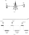
Fig. 1 illustrates awireless communication system 100 to which embodiments of the present application are applied. -
Fig. 2 is a schematic diagram of a random access method according to an embodiment of the present application. -
Fig. 3 is a schematic flowchart of a random access method according to an embodiment of the present application. -
Fig. 4 is a schematic diagram of a method for random access according to another embodiment of the present application. -
Fig. 5 is a schematic flowchart of a method for random access according to an embodiment of the present application. -
Fig. 6 is a schematic block diagram of a random access apparatus according to an embodiment of the present application. -
Fig. 7 is a schematic block diagram of a random access apparatus according to an embodiment of the present application. -
Fig. 8 is a schematic block diagram of a random access apparatus according to an embodiment of the present application. -
Fig. 9 is a schematic block diagram of a random access apparatus according to an embodiment of the present application. - The technical solutions in the embodiments of the present application will be described below with reference to the accompanying drawings.
-
Fig. 1 illustrates awireless communication system 100 to which the embodiments of the present application are applied. Thewireless communication system 100 may include anetwork device 110. Thenetwork device 110 may be a device which communicates with the terminal device. Thenetwork device 100 may provide communication coverage for a particular geographic area and may communicate with the terminal device located within the coverage area. -
Fig. 1 exemplarily shows one network device and two terminals. Optionally, thewireless communication system 100 may include a plurality of network devices and other number of terminals may be included in the coverage of each network device, which is not limited in the embodiment of the present application. - Optionally, the
wireless communication system 100 may further include other network entities such as a network controller, and a mobility management entity, which is not limited in the embodiment of the present application. - It should be understood that the technical solutions of the present application may be applied to various communication systems, for example, a Global System of Mobile communication (GSM) system, a Code Division Multiple Access (CDMA) system, a Wideband Code Division Multiple Access (WCDMA) system, a General Packet Radio Service (GPRS), a Long Term Evolution (LTE) system, an Advanced Long Term Evolution (LTE-A) System, a Universal Mobile Telecommunication System (UMTS), New Radio Access Technology (NR), 5Q and the like.
- It should be understood that, in the embodiments of the present disclosure, the terminal device may include, but is not limited to, a Mobile Station (MS), a Mobile Terminal, a Mobile Telephone, User Equipment (UE), a handset and a portable equipment, etc. The terminal device may communicate with one or more core networks via a Radio Access Network (RAN), for example, the terminal device may be a mobile phone (or "cellular" phone), a computer with a wireless communication function, etc., and the terminal device may also be a portable, pocket, handheld, computer built-in or vehicle-mounted mobile device.
- In the embodiments of the present disclosure, the network device may be an access network device, for example, may be a base station, a Transmit and Receive Point (TRP) or an access point, and the base station may be a Base Transceiver Station (BTS) in GSM or CDMA, or a base station (NodeB) in WCDMA, or an evolved base station (evolved Node B, eNB or e-NodeB) in LTE, or a base station of NR or 5G (gNB), which is not limited in the embodiment of the present application.
-
Fig. 2 is a schematic diagram of a random access method according to an embodiment of the present application. In the existing LTE system, the first step of the terminal for performing the random access process is that the terminal sends a random access signal (also referred to as a random access preamble signal) to the network device. The terminal may use the beam forming technology in the random access process. However, if the beam direction selected by the terminal is inaccurate, the signal quality of the random access signal received by the network device may be reduced, even the random access signal cannot be received by the network device, and finally the terminal cannot complete the random access. At this time, in order to improve the quality of communication between the terminal and the network device, the terminal may allocate different random access signals for different beams, and then the terminal transmits the random access signal corresponding to each beam through different beams. As can be seen from the schematic diagram of the random access method shown inFig. 2 , the terminal can sequentially transmit different random access signals by different beams. For example, after the terminal sends a first random access signal by a first beam, the terminal may detect a first random access response signal corresponding to the first random access signal in a first time window corresponding to the first random access signal. If the first random access response signal is not detected by the terminal in the first time window, the terminal may send a second random access signal by a second beam, and the terminal may detect a second random access response signal corresponding to the second random access signal in a second time window. - However, the above random access mechanism may lead to a too long delay of random access of the terminal. The terminal needs to send the second random access signal by the second beam after waiting for the end of the time window to start the next round of random access process. The above random access mechanism may cause a relatively long delay when the terminal attempts to perform the random access process for many times, and cannot meet the transmission requirement of the service having a relatively high delay requirement.
-
Fig. 3 is a schematic flowchart of a random access method according to an embodiment of the present application. The method shown inFig. 3 includes the following steps. - In 310, in a random access process, a terminal sends a first random access signal by a first resource, and then sends a second random access signal by a second resource.
- Specifically, the terminal sends the first random access signal by the first resource, which may mean that the terminal sends the first random access signal by a first wave speed, and the terminal sends the second random access signal by the second resource, which may mean that the terminal sends the second random access signal by a second wave speed.
- The terminal sends the first random access signal by the first resource, and then sends the second random access signal by the second resource, where the terminal may sequentially send the first random signal by the first resource and send the second random signal by the second resource.
- Optionally, the first random access signal and the second random access signal are preamble signals.
- In 320, the terminal receives at least one of a first random access response signal and a second random access response signal sent by the network device, a start time of a transmission period of the second random access signal being earlier than an end time of a detection period of the first random access response signal.
- Specifically, the terminal may detect the first random access response signal, and when determining that the first random access response signal is a random access response signal of the first random access signal sent by the terminal, the terminal may stop detecting the random access response signal sent by the network device. The terminal may continue to receive the second random access response signal of the second random access signal sent by the network device after determining that the first random access response signal is a random access response signal of the first random access signal sent by the terminal.
- Optionally, the detection period of the first random access response signal and the detection period of the second random access response signal at least partially overlap.
- Specifically, the detection period of the above first random access response signal may be a time window for detecting the first random access response signal by the terminal, the detection period of the above second random access response signal may be a time window for detecting the second random access response signal by the terminal. That is, the above time window for detecting the first random access response signal and the above time window for detecting the second random access response signal may be at least partially overlapped in time.
- Optionally, the first random access signal is sent by a first beam, and the second random access signal is sent by a second beam.
- Specifically, the first random access signal may be sent on the first resource and by the first beam, and the second random access signal may be sent on the second resource and by the second beam.
- The first resource may be at least one of a time domain resource, a frequency domain resource, and a code domain resource, and the second resource may be at least one of a time domain resource, a frequency domain resource, and a code domain resource.
- Optionally, as an embodiment, the method further includes: determining, by the terminal, an uplink target beam according to the first random access response signal and/or the second random access response signal; and communicating, by the terminal, with the network device by the uplink target beam to complete a random access process of the terminal.
- For example, the terminal may send next information of the random access process, such as a connection setup request (MSG3), by the uplink target beam. Since the uplink target beam may be an uplink beam with a relatively good signal quality of transmitting the random access signal among multiple beams, by using the uplink target beam to transmit the MSG3, the signal transmission quality can be ensured, and the successful completion of the random access process can be facilitated.
- Optionally, as an embodiment, the method further includes: detecting, by the terminal, first control information of the first random access response signal and/or second control information of the second random access response signal sent by the network device; and the determining, by the terminal, the uplink target beam according to the first random access response signal and/or the second random access response signal received, includes: determining, by the terminal, an uplink target beam from the first beam and/or the second beam according to the first control information corresponding to the first random access response signal and/or the second control information corresponding to the second random access response signal.
- Optionally, as an embodiment, the determining, by the terminal, the uplink target beam from the first beam and/or the second beam according to the first control information corresponding to the first random access response signal and/or the second control information corresponding to the second random access response signal, includes: determining, by the terminal, the uplink target beam according to a first Random Access-Radio Network Temporary Identity (RA-RNTI) carried by the first control information and/or a second RA-RNTI carried by the second control information.
- Specifically, if the first random access response signal is a response signal with respect to the first random access signal sent by the terminal, the second random access response signal is a response signal with respect to the second random access signal sent by the terminal, and if the terminal may successfully receive the first random access response signal and/or the second random access response signal, the terminal may determine a first beam for sending the first random access signal and/or a second beam for sending the second random access signal according to the first control information corresponding to the first random access response signal and/or the second control information corresponding to the second random access response signal. The terminal may select an uplink target beam from the first beam and/or the second beam, and use information included in the first random access response signal and/or the second random access response signal that has been successfully received, such as a timing advance and a resource allocated by the network device, to complete the random access process of the terminal and the subsequent uplink transmission between the terminal and the network device.
- Optionally, the terminal may select an uplink target beam from the first beam and the second beam, and the beam except the uplink target beam may be used as an alternative beam by the terminal. When the target beam is invalid, the terminal may communicate with the network device through the alternative beam.
- Optionally, the terminal may select a beam with a relatively good signal transmission quality from the first beam and the second beam as the uplink target beam, according to the signal quality of the first random access response signal and the second random access response signal.
- Optionally, the terminal may detect multiple random access response signals in one scheduling unit (for example, one time window), and the terminal may also determine the accuracy of the information carried by the random access response signal and whether there is another random access terminal that has a random access competition with this terminal, according to the content of different random access response signals received.
- Specifically, if three random access response signals are detected by the terminal, and if the time adjustment information carried in the three random access response signals, for example, Timing Advance (TA), is consistent, then the terminal may determine that the information carried by the three random access response signals is relatively accurate. If the TA values carried by two random access response signals (for example, the first random access response signal and the second random access response signal) in the above three random access response signals are consistent, but are inconsistent with the TA value carried by the other random access response signal, the terminal may determine that the random access response signal carrying the TA value inconsistent with the other two random access response signals is sent to another terminal, and said another terminal has a competition-based access relationship with this terminal. The terminal may send a Radio Resource Control (RRC) access request by using the resource allocated by the network device carried in the first two random access response signals, and adjust the sending time of the uplink data by using the TA carried in the first random access response signal and the second random access response signal.
- For another example, after the first random access response signal sent by the network device is detected by the terminal in the first scheduling unit (for example, at least a part of a random access response detection window), the terminal may further detect other scheduling units after the first scheduling unit. If the second random access response signal sent by the network device is detected by the terminal in another scheduling unit, a received signal strength of the second random access response signal is stronger, and there are fewer other terminals that have contention-based random access with the terminal (for example, the terminal may roughly estimate the number of other terminals that are in a contention-based random access relationship according to the different TA values carried in the random access response signals received in the second window), then the terminal may determine the beam of transmitting the second random access signal as the uplink target beam.
-
Fig. 4 is a schematic diagram of a method for random access according to another embodiment of the present application. In the random access method shown inFig. 4 , the terminal sends random access signals to the network device by different beams respectively (the first beam, the second beam, the third beam, and the fourth beam inFig. 4 ). From the detection periods of the random access response signals for the random access signals transmitted by different beams shown inFig. 4 , it can be seen that the detection periods of the random access response signals for the random access signals transmitted by different beams at least partially overlap in time. (Referring to the detection period of the first random access response signal, the detection period of the second random access response signal, and the detection period of the third random access response signal shown inFig. 4 ), the terminal may detect a plurality of random access response signals sent by the network device from a start time of the detection period of the first random access response signal to an end time of the detection period of the third random access response signal, and determine a target random access response signals from the plurality of random access response signals. -
Fig. 5 is a schematic flowchart of a method for random access according to an embodiment of the present application. The method shown inFig. 5 includes the following steps. - In 510, in a random access process, the network device detects a first random access signal by a first resource, and then detects a second random access signal by a second resource.
- The network device detects the first random access signal by the first resource, and then detects the second random access signal by the second resource, which may mean that the terminal sequentially detects the first random signal on the first resource and the second random signal on the second resource.
- In 520, the network device sends at least one of a first random access response signal and a second random access response signal, where a start time of a transmission period of the second random access signal is earlier than an end time of a sending period of the first random access response signal.
- Specifically, the sending period of the first random access response signal mentioned above may refer to a detection period during which the terminal detects the first random access response signal.
- Optionally, as an embodiment, the sending period of the first random access response signal and the sending period of the second random access response signal at least partially overlap.
- Specifically, the sending period of the first random access response signal and the sending period of the second random access response signal at least partially overlap, which may mean that the detection period of detecting the first random access response signal and the detection period of detecting the second random access response signal by the terminal are at least partially overlapped.
- Optionally, as an embodiment, the first random access signal is sent by a first beam of the terminal, and the second random access signal is sent by a second beam of the terminal.
- Optionally, as an embodiment, the first resource includes at least one of a time domain resource, a frequency domain resource, and a code domain resource, and the second resource includes at least one of a time domain resource, a frequency domain resource, and a code domain resource.
- Optionally, as an embodiment, the first random access signal and the second random access signal are preamble signals.
- Optionally, as an embodiment, the method further includes: sending, by the network device, first control information of the first random access response signal and/or second control information of the second random access response signal; and communicating, by the network device, with the terminal by receiving an uplink target beam to complete the random access process of the terminal, the uplink target beam being a first beam determined by the first control information or a second beam determined by using the second control information.
- Optionally, as an embodiment, the first control information carries a first RA-RNTI and/or the second control information carries the second RA-RNTI, where the first RA-RNTI is used to indicate the first beam, and the second RA-RNTI is used to indicate the second beam.
- The method of random access in the embodiments of the present application is described in detail above with reference to
Fig. 1 to Fig. 5 , and the apparatus of random access in the embodiments of the present application will be described in detail below with reference toFig. 6 to Fig. 9 . It should be understood that the apparatus shown inFig. 6 to Fig. 9 can implement the various steps inFig. 3 , and details are not described here again to avoid repetition. -
Fig. 6 is a schematic block diagram of a random access apparatus according to an embodiment of the present application. The apparatus 600 shown inFig. 6 includes: a sendingunit 610 and afirst detection unit 620. - The sending
unit 610 is configured to, in a random access process, send a first random access signal by a first resource, and then send a second random access signal by a second resource. - The
first detection unit 620 is configured to detect at least one of the first random access response signal and the second random access response signal sent by the network device, wherein a starting time of a transmission period of the second random access signal is earlier than an ending time of a detection period of the first random access response signal. - Optionally, as an embodiment, the detection period of the first random access response signal and the detection period of the second random access response signal at least partially overlap.
- Optionally, as an embodiment, the first random access signal is sent by a first beam, and the second random access signal is sent by a second beam.
- Optionally, as an embodiment, the first resource includes at least one of a time domain resource, a frequency domain resource, and a code domain resource, and the second resource includes at least one of a time domain resource, a frequency domain resource, and a code domain resource.
- Optionally, as an embodiment, the first random access signal and the second random access signal are preamble signals.
- Optionally, as an embodiment, the apparatus further includes: a determination unit, configured to determine an uplink target beam, according to the first random access response signal and/or the second random access response signal; and a communication unit, configured to communicate with the network device by using the uplink target beam to complete the random access process of the terminal.
- Optionally, as an embodiment, the apparatus further includes: a second detection unit, configured to detect first control information of the first random access response signal and/or second control information of the second random access response signal which are sent by the network device; and the determination unit is specifically configured to determine the uplink target beam from the first beam and/or the second beam according to the first control information corresponding to the first random access response signal received and/or the second control information corresponding to the second random access response signal received.
- Optionally, as an embodiment, the determination unit is further configured to determine the uplink target beam according to a first Random Access-Radio Network Temporary Identifier (RA-RNTI) carried by the first control information and/or a second RA-RNTI carried by the second control information.
-
Fig. 7 is a schematic block diagram of a random access apparatus according to an embodiment of the present application. The apparatus shown inFig. 7 includes: adetection unit 710, and afirst sending unit 720. - The
detection unit 710 is configured to detect a first random access signal through a first resource, and then detect a second random access signal by a second resource in a random access process. - The
first sending unit 720 is configured to send at least one of the first random access response signal and the second random access response signal, where a start time of a transmission period of the second random access signal is earlier than an end time of a sending period of the first random access response signal. - Optionally, as an embodiment, the sending period of the first random access response signal and the sending period of the second random access response signal at least partially overlap.
- Optionally, as an embodiment, the first random access signal is sent by a first beam of the terminal, and the second random access signal is sent by a second beam of the terminal.
- Optionally, as an embodiment, the first resource includes at least one of a time domain resource, a frequency domain resource, and a code domain resource, and the second resource includes at least one of a time domain resource, a frequency domain resource, and a code domain resource.
- Optionally, as an embodiment, the first random access signal and the second random access signal are preamble signals.
- Optionally, as an embodiment, the apparatus further includes: a second sending unit, configured to send first control information of the first random access response signal and/or second control information of the second random access response signal; and a communication unit, configured to communicate with the terminal by receiving an uplink target beam, to complete the random access process of the terminal, where the uplink target beam is a first beam determined by the first control information or a second beam determined by the second control information.
- Optionally, as an embodiment, the first control information carries a first Random Access-Radio Network Temporary Identifier (RA-RNTI) and/or the second control information carries a second RA-RNTI, where the first RA-RNTI is configured to indicate the first beam, and the second RA-RNTI is used to indicate the second beam.
-
Fig. 8 is a schematic block diagram of a random access apparatus according to an embodiment of the present application. The apparatus 800 shown inFig. 8 includes: atransceiver 810 and aprocessor 820. - The
transceiver 810 is configured to send a first random access signal through a first resource first, and then send a second random access signal through a second resource in a random access process. - The
processor 820 is configured to detect at least one of a first random access response signal and a second random access response signal sent by a network device, where a starting time of a transmission period of the second random access signal is earlier than an ending time of a detection period of the first random access response signal. - Optionally, as an embodiment, the detection period of the first random access response signal and a detection period of the second random access response signal at least partially overlap.
- Optionally, as an embodiment, the first random access signal is sent by a first beam, and the second random access signal is sent by a second beam.
- Optionally, as an embodiment, the first resource includes at least one of a time domain resource, a frequency domain resource, and a code domain resource, and the second resource includes at least one of a time domain resource, a frequency domain resource, and a code domain resource.
- Optionally, as an embodiment, the first random access signal and the second random access signal are preamble signals.
- Optionally, as an embodiment, the apparatus further includes: the processor being configured to determine an uplink target beam, according to the first random access response signal and/or the second random access response signal received; and the transceiver being configured to communicate with the network device by using the uplink target beam to complete the random access process of the terminal.
- Optionally, as an embodiment, the apparatus further includes: the processor being configured to detect first control information of the first random access response signal and/or second control information of the second random access response signal which are sent by the network device; and determine the uplink target beam from the first beam and/or the second beam according to the first control information corresponding to the first random access response signal received and/or the second control information corresponding to the second random access response signal received.
- Optionally, as an embodiment, the determination unit is further configured to determine the uplink target beam according to a first Random Access-Radio Network Temporary Identity (RA-RNTI) carried by the first control information and/or a second RA-RNTI carried by the second control information.
-
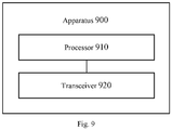
Fig. 9 is a schematic block diagram of a random access apparatus according to an embodiment of the present application. The apparatus 900 shown inFig. 9 includes: aprocessor 910 and atransceiver 920. - The
processor 910 is configured to detect a first random access signal by a first resource, and then detect a second random access signal through a second resource in a random access process. - The
transceiver 920 is configured to send at least one of a first random access response signal and a second random access response signal sent by the network device, wherein a starting time of a transmission period of the second random access signal is earlier than an ending time of a detection period of the first random access response signal. - Optionally, as an embodiment, the detection period of the first random access response signal and a detection period of the second random access response signal at least partially overlap.
- Optionally, as an embodiment, the first random access signal is sent by a first beam, and the second random access signal is sent by a second beam.
- Optionally, as an embodiment, the first resource includes at least one of a time domain resource, a frequency domain resource, and a code domain resource, and the second resource includes at least one of a time domain resource, a frequency domain resource, and a code domain resource.
- Optionally, as an embodiment, the first random access signal and the second random access signal are preamble signals.
- Optionally, as an embodiment, the apparatus further includes: the
transceiver 920 being configured to send first control information of the first random access response signal and/or second control information of the second random access response signal; and configured to communicate with the terminal by an uplink target beam, to complete the random access process of the terminal, where the target beam is a first beam corresponding to the first control information or a second beam corresponding to the second control information. - Optionally, as an embodiment, the first control information carries a first Random Access-Radio Network Temporary Identity (RA-RNTI) and/or the second control information carries a second RA-RNTI, where the first RA-RNTI is used to indicate the first beam, and the second RA-RNTI is used to indicate the second beam.
- It should be understood that in the embodiments of the present application, "B corresponding to A" means that B is associated with A, and B can be determined according to A. However, it should also be understood that determining B from A does not mean that B is only determined based on A, and B can also be determined based on A and/or other information.
- It should be understood that the term "and/or" herein is merely used for describing an association relationship of associated objects, and indicates that there may be three relationships, for example, A and/or B, may represent three situations: A exists alone, A and B coexist, and B exists alone. In addition, the character "/" herein generally indicates that the contextual objects are of an "or" relationship.
- It should be understood that in various embodiments of the present application, the size of the sequence numbers of the above-mentioned processes does not mean the order of execution, and the order of execution of each process should be determined by its function and internal logic, and should not constitute any limitation on the implementation process of the embodiments of the present application.
- In the several embodiments provided in the present application, it should be understood that the disclosed systems, apparatuses and methods may be implemented in other ways. For example, the apparatus embodiments described above are merely illustrative. For example, the division of the units is only a kind of logical function division. In practice, other division manner may be used. For example, multiple units or components may be combined or integrated into another system, or some features may be ignored or not performed. In addition, the illustrated or discussed mutual coupling or direct coupling or communication connection may be indirect coupling or communication connection through some interfaces, apparatuses or units, and may be in electrical, mechanical or other forms.
- The units described as separated parts may or may not be physically separated, and the parts displayed as units may or may not be physical units, that is, may be located in one place, or may be distributed on multiple network units. Some or all of the units may be selected according to actual needs to achieve the objectives of the solutions in the embodiments.
- In addition, individual functional units in individual embodiments of the present application may be integrated in one processing unit, or individual units may exist alone physically, or two or more units may be integrated into one unit.
- The functions may also be stored in a computer-readable storage medium if being implemented in the form of a software functional unit and sold or used as an independent product. Based on such understanding, the essence of the technical solutions of the present application, or the part contributing to the related art or all or a part of the technical solutions, may be embodied in the form of a software product. The computer software product is stored in storage medium including a number of instructions such that a computer device (which may be a personal computer, a server, or a network device, etc.) performs all or a part of steps of the method described in each of the embodiments of the present application. The foregoing storage medium includes: any medium that is capable of storing program codes such as a USB disk, a mobile hard disk, a Read-Only Memory (ROM), a Random Access Memory (RAM), a magnetic disk or an optical disk, and the like.
Claims (8)
- A random access method, comprising:in a random access process, detecting a first random access signal via a first resource, and then detecting a second random access signal via a second resource, by a network device; andsending, by the network device, at least one of a first random access response signal and a second random access response signal, a start time of a transmission period of the second random access signal being earlier than an end time of a sending period of the first random access response signal.
- The method according to claim 1, wherein, the sending period of the first random access response signal and a sending period of the second random access response signal at least partially overlap.
- The method according to claim 1 or 2, wherein, the first random access signal is sent by a first beam of the terminal, and the second random access signal is sent by a second beam of the terminal.
- The method according to any one of claims 1 to 3, wherein, the first resource comprises at least one of a time domain resource, a frequency domain resource, and a code domain resource, and the second resource comprises at least one of a time domain resource, a frequency domain resource, and a code domain resource.
- The method according to any one of claims 1 to 4, wherein, the first random access signal and the second random access signal are preamble signals.
- The method according to any one of claims 1 to 5, further comprising:sending, by the network device, first control information of the first random access response signal and/or second control information of the second random access response signal; andcommunicating, by the network device, with the terminal by receiving an uplink target beam to complete the random access process of the terminal, the uplink target beam being a first beam determined by the first control information or a second beam determined by using the second control information.
- The method according to claim 6, wherein, the first control information carries a first Random Access-Radio Network Temporary Identity (RA-RNTI) and/or the second control information carries a second RA-RNTI, the first RA-RNTI is used to indicate the first beam, and the second RA-RNTI is used to indicate the second beam.
- A random access apparatus, comprising:a processor (920); anda memory for storing instructions executable by the processor (920);wherein the processor (920) is configured to perform the random access method according to any one of claims 1-7.
Priority Applications (1)
| Application Number | Priority Date | Filing Date | Title |
|---|---|---|---|
| EP20187456.7A EP3761749A1 (en) | 2016-12-26 | 2016-12-26 | Random access method and apparatus |
Applications Claiming Priority (3)
| Application Number | Priority Date | Filing Date | Title |
|---|---|---|---|
| EP16924999.2A EP3531784B1 (en) | 2016-12-26 | 2016-12-26 | Random access method and apparatus |
| PCT/CN2016/112211 WO2018119613A1 (en) | 2016-12-26 | 2016-12-26 | Random access method and apparatus |
| EP20187456.7A EP3761749A1 (en) | 2016-12-26 | 2016-12-26 | Random access method and apparatus |
Related Parent Applications (2)
| Application Number | Title | Priority Date | Filing Date |
|---|---|---|---|
| EP16924999.2A Division EP3531784B1 (en) | 2016-12-26 | 2016-12-26 | Random access method and apparatus |
| EP16924999.2A Division-Into EP3531784B1 (en) | 2016-12-26 | 2016-12-26 | Random access method and apparatus |
Publications (1)
| Publication Number | Publication Date |
|---|---|
| EP3761749A1 true EP3761749A1 (en) | 2021-01-06 |
Family
ID=62706600
Family Applications (2)
| Application Number | Title | Priority Date | Filing Date |
|---|---|---|---|
| EP16924999.2A Active EP3531784B1 (en) | 2016-12-26 | 2016-12-26 | Random access method and apparatus |
| EP20187456.7A Withdrawn EP3761749A1 (en) | 2016-12-26 | 2016-12-26 | Random access method and apparatus |
Family Applications Before (1)
| Application Number | Title | Priority Date | Filing Date |
|---|---|---|---|
| EP16924999.2A Active EP3531784B1 (en) | 2016-12-26 | 2016-12-26 | Random access method and apparatus |
Country Status (5)
| Country | Link |
|---|---|
| US (1) | US11051342B2 (en) |
| EP (2) | EP3531784B1 (en) |
| CN (2) | CN110073713B (en) |
| TW (1) | TWI663889B (en) |
| WO (1) | WO2018119613A1 (en) |
Families Citing this family (6)
| Publication number | Priority date | Publication date | Assignee | Title |
|---|---|---|---|---|
| CN108923896B (en) | 2017-04-19 | 2021-03-26 | 上海朗帛通信技术有限公司 | Method and device used in paging user equipment and base station |
| EP3621375A4 (en) * | 2017-05-05 | 2020-11-04 | Beijing Xiaomi Mobile Software Co., Ltd. | Method, user equipment unit, and base station for controlling random access to network |
| US10887803B2 (en) * | 2017-05-12 | 2021-01-05 | Telefonaktiebolaget Lm Ericsson (Publ) | Radio network node, wireless device, and methods for performing random access in a wireless communication network |
| CN110475338B (en) * | 2018-05-11 | 2021-09-07 | 华为技术有限公司 | Uplink transmission method and user equipment |
| WO2020062070A1 (en) * | 2018-09-28 | 2020-04-02 | 华为技术有限公司 | Random access method and random access device |
| CN116347644A (en) * | 2021-12-23 | 2023-06-27 | 中国移动通信有限公司研究院 | Message sending method, message receiving method and device |
Citations (2)
| Publication number | Priority date | Publication date | Assignee | Title |
|---|---|---|---|---|
| WO2016045715A1 (en) * | 2014-09-24 | 2016-03-31 | Nokia Solutions And Networks Oy | Repeated transmission of scheduling assignment for random access response |
| US20160227575A1 (en) * | 2015-01-30 | 2016-08-04 | Telefonaktiebolaget L M Ericsson (Publ) | Random-access response with analog beamforming |
Family Cites Families (46)
| Publication number | Priority date | Publication date | Assignee | Title |
|---|---|---|---|---|
| GB2419495B (en) * | 2004-10-22 | 2007-03-21 | Roke Manor Research | Communications method and apparatus |
| CN101175309A (en) * | 2006-11-02 | 2008-05-07 | 北京三星通信技术研究有限公司 | Device and method for transmission of accidental access response message |
| CN101316134B (en) * | 2007-05-31 | 2012-09-05 | 电信科学技术研究院 | Accidental access method and corresponding terminal and base station adopting the same |
| CN101370270A (en) | 2007-08-13 | 2009-02-18 | 中兴通讯股份有限公司 | Accidental access method for honeycomb wireless communication system |
| CN101478778B (en) | 2008-01-04 | 2012-05-09 | 中兴通讯股份有限公司 | Cellular communication system random access method and parameter transmission method |
| EP2757846B1 (en) * | 2008-04-24 | 2016-03-09 | Huawei Technologies Co., Ltd. | Mobile station device, mobile communication system, and communication method |
| US8576780B2 (en) * | 2009-03-22 | 2013-11-05 | Lg Electronics Inc. | Random access response processing |
| KR101803015B1 (en) * | 2010-02-10 | 2017-12-01 | 주식회사 골드피크이노베이션즈 | Method and apparatus for configuring uplink synchronization in component carrier aggregation |
| CN102238752B (en) * | 2010-04-30 | 2014-02-12 | 电信科学技术研究院 | Random access control method of machine type communication (MTC) equipment and MTC equipment |
| JP5331763B2 (en) * | 2010-08-20 | 2013-10-30 | パナソニック株式会社 | Network management device, base station device, and network management method |
| CN102548012B (en) | 2010-12-22 | 2019-03-15 | 中兴通讯股份有限公司 | A kind of accidental access method and terminal |
| US9585083B2 (en) * | 2011-06-17 | 2017-02-28 | Samsung Electronics Co., Ltd. | Apparatus and method for supporting network entry in a millimeter-wave mobile broadband communication system |
| CN102325382B (en) * | 2011-06-30 | 2016-01-20 | 电信科学技术研究院 | Accidental access method and equipment |
| US8395985B2 (en) * | 2011-07-25 | 2013-03-12 | Ofinno Technologies, Llc | Time alignment in multicarrier OFDM network |
| US9107173B2 (en) * | 2011-07-28 | 2015-08-11 | Blackberry Limited | Method and system for access and uplink power control for a wireless system having multiple transmit points |
| CN103002526B (en) * | 2011-09-13 | 2015-06-03 | 华为技术有限公司 | Cell handover control methods, cell measurement method, equipment and system |
| CN103220813B (en) * | 2012-01-20 | 2018-08-07 | 中兴通讯股份有限公司 | The accidental access method and system and terminal and base station equipment of a kind of multicarrier system |
| CN103228053A (en) * | 2012-01-29 | 2013-07-31 | 中兴通讯股份有限公司 | Random access method of multi-carrier system, base station, as well as mobile terminal and random access system |
| WO2013138701A2 (en) * | 2012-03-16 | 2013-09-19 | Interdigital Patent Holdings, Inc. | Random access procedures in wireless systems |
| CN103546963B (en) * | 2012-07-10 | 2016-09-14 | 电信科学技术研究院 | A kind of method and apparatus determining location information |
| EP2876955B1 (en) * | 2012-08-10 | 2017-11-15 | Huawei Technologies Co., Ltd. | Method and bs for random access |
| US9468022B2 (en) * | 2012-12-26 | 2016-10-11 | Samsung Electronics Co., Ltd. | Method and apparatus for random access in communication system with large number of antennas |
| KR20140109633A (en) * | 2013-03-06 | 2014-09-16 | 삼성전자주식회사 | Method and apparatus for transmission and reception of uplink random access channel slot in a radio communication system using beamforming |
| KR102026256B1 (en) * | 2013-05-21 | 2019-11-04 | 삼성전자주식회사 | Scheme for transmitting/receiving rach signal in beamforming systems |
| CN105359594B (en) * | 2013-07-12 | 2019-09-27 | 夏普株式会社 | Terminal installation, method and integrated circuit |
| WO2015012664A1 (en) * | 2013-07-26 | 2015-01-29 | 엘지전자 주식회사 | Method for transmitting signal for mtc and apparatus for same |
| CN105264999B (en) * | 2013-09-16 | 2020-01-31 | 华为技术有限公司 | Method for predetermining resources in random access, user equipment and base station |
| CN105284174A (en) | 2013-10-28 | 2016-01-27 | 华为技术有限公司 | Random access method, random access configuration method, device and system |
| US20150201448A1 (en) * | 2014-01-13 | 2015-07-16 | Qualcomm Incorporated | Uplink pilot channel positioning for circuit switched fallback |
| KR102391121B1 (en) * | 2014-01-29 | 2022-04-27 | 인터디지탈 패튼 홀딩스, 인크 | Method of access and link adaptation for coverage enhanced wireless transmissions |
| PL3123802T3 (en) * | 2014-03-25 | 2019-02-28 | Telefonaktiebolaget Lm Ericsson (Publ) | System and method for beam-based physical random-access |
| KR102171561B1 (en) * | 2014-04-07 | 2020-10-29 | 삼성전자주식회사 | Method and apparatus for uplink beam tracking in beamforming based cellular systems |
| CN115483956A (en) * | 2014-11-26 | 2022-12-16 | Idac控股公司 | Initial access in high frequency wireless systems |
| WO2016122258A1 (en) * | 2015-01-29 | 2016-08-04 | 엘지전자 주식회사 | Signal receiving method and user equipment, and signal receiving method and base station |
| US10595280B2 (en) * | 2015-03-06 | 2020-03-17 | Qualcomm Incorporated | Repetition level coverage enhancement techniques for physical random access channel transmissions |
| US9918344B2 (en) * | 2015-04-09 | 2018-03-13 | Intel IP Corporation | Random access procedure for enhanced coverage support |
| WO2017022870A1 (en) * | 2015-08-03 | 2017-02-09 | Samsung Electronics Co., Ltd. | Method and apparatus for initial access in wireless communication system |
| WO2017146550A1 (en) * | 2016-02-26 | 2017-08-31 | Samsung Electronics Co., Ltd. | Apparatus and method for performing random access in beam-formed system |
| EP3419340B1 (en) * | 2016-03-11 | 2024-05-01 | LG Electronics Inc. | System information signal reception method, user equipment, system information signal transmitting method and base station |
| US10615862B2 (en) * | 2016-04-13 | 2020-04-07 | Qualcomm Incorporated | System and method for beam adjustment request |
| US10630410B2 (en) * | 2016-05-13 | 2020-04-21 | Telefonaktiebolaget Lm Ericsson (Publ) | Network architecture, methods, and devices for a wireless communications network |
| US10111255B2 (en) * | 2016-05-16 | 2018-10-23 | Qualcomm Incorporated | Beam and symbol selection to transmit RACH |
| EP3823391B1 (en) * | 2016-07-20 | 2023-08-30 | IPLA Holdings Inc. | Mobility for radio devices using beamforming |
| CN106255212B (en) * | 2016-07-29 | 2019-07-16 | Oppo广东移动通信有限公司 | Secondary member carrier configuration method and device, mobile terminal, base station, communication system |
| US10412768B2 (en) * | 2016-11-09 | 2019-09-10 | Telefonaktiebolaget Lm Ericsson (Publ) | Method and devices of performing a random access procedure between a user equipment, UE, and a radio access network of a telecommunication network |
| US9900891B1 (en) * | 2016-12-20 | 2018-02-20 | Qualcomm Incorporated | Fallback beam selection procedure during failure of beam change instruction reception |
-
2016
- 2016-12-26 CN CN201680091424.0A patent/CN110073713B/en active Active
- 2016-12-26 CN CN202010976862.3A patent/CN112087814B/en active Active
- 2016-12-26 WO PCT/CN2016/112211 patent/WO2018119613A1/en unknown
- 2016-12-26 US US16/463,066 patent/US11051342B2/en active Active
- 2016-12-26 EP EP16924999.2A patent/EP3531784B1/en active Active
- 2016-12-26 EP EP20187456.7A patent/EP3761749A1/en not_active Withdrawn
-
2017
- 2017-12-07 TW TW106142929A patent/TWI663889B/en not_active IP Right Cessation
Patent Citations (2)
| Publication number | Priority date | Publication date | Assignee | Title |
|---|---|---|---|---|
| WO2016045715A1 (en) * | 2014-09-24 | 2016-03-31 | Nokia Solutions And Networks Oy | Repeated transmission of scheduling assignment for random access response |
| US20160227575A1 (en) * | 2015-01-30 | 2016-08-04 | Telefonaktiebolaget L M Ericsson (Publ) | Random-access response with analog beamforming |
Non-Patent Citations (5)
| Title |
|---|
| INTERDIGITAL: "Random access aspects for beam-based NR initial access", vol. RAN WG1, no. Gothenburg, Sweden; 20160822 - 20160826, 21 August 2016 (2016-08-21), XP051125851, Retrieved from the Internet <URL:http://www.3gpp.org/ftp/Meetings_3GPP_SYNC/RAN1/Docs/> [retrieved on 20160821] * |
| NTT DOCOMO ET AL: "Design for RACH Procedure for NR", vol. RAN WG1, no. Göteborg; 20160822 - 20160826, 13 August 2016 (2016-08-13), XP051133032, Retrieved from the Internet <URL:http://www.3gpp.org/ftp/tsg_ran/WG1_RL1/TSGR1_86/Docs/> [retrieved on 20160813] * |
| SAMSUNG: "Random Access Procedure in NR", vol. RAN WG2, no. Gothenburg, Sweden; 20160822 - 20160826, 21 August 2016 (2016-08-21), XP051126468, Retrieved from the Internet <URL:http://www.3gpp.org/ftp/Meetings_3GPP_SYNC/RAN2/Docs/> [retrieved on 20160821] * |
| ZTE ET AL: "Unified random access in NR", vol. RAN WG1, no. Lisbon, Portugal; 20161010 - 20161014, 9 October 2016 (2016-10-09), XP051149021, Retrieved from the Internet <URL:http://www.3gpp.org/ftp/Meetings_3GPP_SYNC/RAN1/Docs/> [retrieved on 20161009] * |
| ZTE ZTE MICROELECTRONICS: "WF on Message 2 reception window", vol. RAN WG1, no. Reno, USA; 20161114 - 20161118, 19 November 2016 (2016-11-19), XP051191535, Retrieved from the Internet <URL:http://www.3gpp.org/ftp/tsg_ran/WG1_RL1/TSGR1_87/Docs/> [retrieved on 20161119] * |
Also Published As
| Publication number | Publication date |
|---|---|
| TWI663889B (en) | 2019-06-21 |
| WO2018119613A1 (en) | 2018-07-05 |
| EP3531784B1 (en) | 2020-09-09 |
| CN112087814B (en) | 2022-10-28 |
| US20190281639A1 (en) | 2019-09-12 |
| CN112087814A (en) | 2020-12-15 |
| CN110073713B (en) | 2020-10-20 |
| EP3531784A1 (en) | 2019-08-28 |
| US11051342B2 (en) | 2021-06-29 |
| EP3531784A4 (en) | 2019-10-23 |
| CN110073713A (en) | 2019-07-30 |
| TW201824929A (en) | 2018-07-01 |
Similar Documents
| Publication | Publication Date | Title |
|---|---|---|
| US11051342B2 (en) | Random access method and apparatus | |
| CN111246590B (en) | Data transmission method and related product | |
| CN104322134B (en) | Access method, device and base station | |
| WO2019154272A1 (en) | Beam failure recovery method and user terminal | |
| CN107624260B (en) | TA acquisition method and device | |
| CN107404749B (en) | Communication connection method and base station | |
| EP3490275B1 (en) | Method for transmitting data, terminal device and network-side device | |
| CN111615215A (en) | Communication method, terminal equipment and network equipment | |
| CN108633100B (en) | Method and apparatus for random access response and method and apparatus for random access | |
| EP3579446A1 (en) | Method for use in transmitting signal, terminal device, and network device | |
| CN111727656B (en) | Method, network equipment and terminal equipment for random access | |
| WO2023198022A1 (en) | Random access method, and device | |
| CN109963350A (en) | Message receival method and terminal | |
| CN111886918B (en) | Random access method and device | |
| WO2021077343A1 (en) | Wireless communication method and terminal device | |
| US20230058891A1 (en) | Information sending method, information receiving method, terminal and network device | |
| EP3606181B1 (en) | Method for terminal device to access network and terminal device | |
| CN112929978B (en) | Preamble transmission method and apparatus, and computer-readable storage medium | |
| CN110024472B (en) | Method and apparatus for random access | |
| JP2023519396A (en) | Method performed by terminal device and terminal device | |
| CN112868267A (en) | Random access method, terminal equipment and network equipment | |
| CN112567871A (en) | Random access preamble transmission | |
| US20220225433A1 (en) | Wireless communication method, terminal device, and network device | |
| CN112788712B (en) | Detection method of random access response RAR, terminal equipment and network equipment | |
| WO2023006514A1 (en) | Conditional fallback configuration for mcg-rlf |
Legal Events
| Date | Code | Title | Description |
|---|---|---|---|
| PUAI | Public reference made under article 153(3) epc to a published international application that has entered the european phase |
Free format text: ORIGINAL CODE: 0009012 |
|
| STAA | Information on the status of an ep patent application or granted ep patent |
Free format text: STATUS: THE APPLICATION HAS BEEN PUBLISHED |
|
| AC | Divisional application: reference to earlier application |
Ref document number: 3531784 Country of ref document: EP Kind code of ref document: P |
|
| AK | Designated contracting states |
Kind code of ref document: A1 Designated state(s): AL AT BE BG CH CY CZ DE DK EE ES FI FR GB GR HR HU IE IS IT LI LT LU LV MC MK MT NL NO PL PT RO RS SE SI SK SM TR |
|
| STAA | Information on the status of an ep patent application or granted ep patent |
Free format text: STATUS: REQUEST FOR EXAMINATION WAS MADE |
|
| 17P | Request for examination filed |
Effective date: 20210319 |
|
| RBV | Designated contracting states (corrected) |
Designated state(s): AL AT BE BG CH CY CZ DE DK EE ES FI FR GB GR HR HU IE IS IT LI LT LU LV MC MK MT NL NO PL PT RO RS SE SI SK SM TR |
|
| STAA | Information on the status of an ep patent application or granted ep patent |
Free format text: STATUS: EXAMINATION IS IN PROGRESS |
|
| 17Q | First examination report despatched |
Effective date: 20210521 |
|
| STAA | Information on the status of an ep patent application or granted ep patent |
Free format text: STATUS: THE APPLICATION IS DEEMED TO BE WITHDRAWN |
|
| 18D | Application deemed to be withdrawn |
Effective date: 20220608 |