EP3280161B1 - Speaker system - Google Patents
Speaker system Download PDFInfo
- Publication number
- EP3280161B1 EP3280161B1 EP17187840.8A EP17187840A EP3280161B1 EP 3280161 B1 EP3280161 B1 EP 3280161B1 EP 17187840 A EP17187840 A EP 17187840A EP 3280161 B1 EP3280161 B1 EP 3280161B1
- Authority
- EP
- European Patent Office
- Prior art keywords
- sound
- loudspeaker
- array
- listening
- transducers
- Prior art date
- Legal status (The legal status is an assumption and is not a legal conclusion. Google has not performed a legal analysis and makes no representation as to the accuracy of the status listed.)
- Active
Links
- 230000005855 radiation Effects 0.000 claims description 9
- 230000000694 effects Effects 0.000 claims description 8
- 230000006870 function Effects 0.000 claims description 8
- 230000005236 sound signal Effects 0.000 claims description 6
- 238000012546 transfer Methods 0.000 claims description 5
- 238000010521 absorption reaction Methods 0.000 claims description 3
- 238000003491 array Methods 0.000 description 37
- 238000013459 approach Methods 0.000 description 13
- 238000000926 separation method Methods 0.000 description 13
- 230000008901 benefit Effects 0.000 description 9
- 238000010586 diagram Methods 0.000 description 8
- 238000009434 installation Methods 0.000 description 5
- 238000002604 ultrasonography Methods 0.000 description 5
- 230000015572 biosynthetic process Effects 0.000 description 4
- 238000005516 engineering process Methods 0.000 description 3
- 230000009467 reduction Effects 0.000 description 3
- 230000002787 reinforcement Effects 0.000 description 3
- 238000004891 communication Methods 0.000 description 2
- 239000004020 conductor Substances 0.000 description 2
- 238000013461 design Methods 0.000 description 2
- 230000005484 gravity Effects 0.000 description 2
- 238000012545 processing Methods 0.000 description 2
- 208000000913 Kidney Calculi Diseases 0.000 description 1
- 241000291281 Micropterus treculii Species 0.000 description 1
- 206010029148 Nephrolithiasis Diseases 0.000 description 1
- 230000003044 adaptive effect Effects 0.000 description 1
- 230000002411 adverse Effects 0.000 description 1
- 230000005540 biological transmission Effects 0.000 description 1
- 239000000969 carrier Substances 0.000 description 1
- 230000008878 coupling Effects 0.000 description 1
- 238000010168 coupling process Methods 0.000 description 1
- 238000005859 coupling reaction Methods 0.000 description 1
- 230000006735 deficit Effects 0.000 description 1
- 230000001419 dependent effect Effects 0.000 description 1
- 210000005069 ears Anatomy 0.000 description 1
- 230000002349 favourable effect Effects 0.000 description 1
- 239000011521 glass Substances 0.000 description 1
- 230000004886 head movement Effects 0.000 description 1
- 230000036541 health Effects 0.000 description 1
- 230000002452 interceptive effect Effects 0.000 description 1
- 230000007257 malfunction Effects 0.000 description 1
- 239000012528 membrane Substances 0.000 description 1
- 238000000034 method Methods 0.000 description 1
- 238000012986 modification Methods 0.000 description 1
- 230000004048 modification Effects 0.000 description 1
- 230000008447 perception Effects 0.000 description 1
- 230000035945 sensitivity Effects 0.000 description 1
- 230000001629 suppression Effects 0.000 description 1
- 238000003786 synthesis reaction Methods 0.000 description 1
Images


Classifications
-
- H—ELECTRICITY
- H04—ELECTRIC COMMUNICATION TECHNIQUE
- H04R—LOUDSPEAKERS, MICROPHONES, GRAMOPHONE PICK-UPS OR LIKE ACOUSTIC ELECTROMECHANICAL TRANSDUCERS; DEAF-AID SETS; PUBLIC ADDRESS SYSTEMS
- H04R5/00—Stereophonic arrangements
- H04R5/04—Circuit arrangements, e.g. for selective connection of amplifier inputs/outputs to loudspeakers, for loudspeaker detection, or for adaptation of settings to personal preferences or hearing impairments
-
- H—ELECTRICITY
- H04—ELECTRIC COMMUNICATION TECHNIQUE
- H04R—LOUDSPEAKERS, MICROPHONES, GRAMOPHONE PICK-UPS OR LIKE ACOUSTIC ELECTROMECHANICAL TRANSDUCERS; DEAF-AID SETS; PUBLIC ADDRESS SYSTEMS
- H04R3/00—Circuits for transducers, loudspeakers or microphones
- H04R3/12—Circuits for transducers, loudspeakers or microphones for distributing signals to two or more loudspeakers
- H04R3/14—Cross-over networks
-
- H—ELECTRICITY
- H04—ELECTRIC COMMUNICATION TECHNIQUE
- H04S—STEREOPHONIC SYSTEMS
- H04S3/00—Systems employing more than two channels, e.g. quadraphonic
-
- H—ELECTRICITY
- H04—ELECTRIC COMMUNICATION TECHNIQUE
- H04S—STEREOPHONIC SYSTEMS
- H04S7/00—Indicating arrangements; Control arrangements, e.g. balance control
- H04S7/30—Control circuits for electronic adaptation of the sound field
- H04S7/302—Electronic adaptation of stereophonic sound system to listener position or orientation
- H04S7/303—Tracking of listener position or orientation
-
- H—ELECTRICITY
- H04—ELECTRIC COMMUNICATION TECHNIQUE
- H04S—STEREOPHONIC SYSTEMS
- H04S7/00—Indicating arrangements; Control arrangements, e.g. balance control
- H04S7/30—Control circuits for electronic adaptation of the sound field
- H04S7/307—Frequency adjustment, e.g. tone control
-
- H—ELECTRICITY
- H04—ELECTRIC COMMUNICATION TECHNIQUE
- H04R—LOUDSPEAKERS, MICROPHONES, GRAMOPHONE PICK-UPS OR LIKE ACOUSTIC ELECTROMECHANICAL TRANSDUCERS; DEAF-AID SETS; PUBLIC ADDRESS SYSTEMS
- H04R2203/00—Details of circuits for transducers, loudspeakers or microphones covered by H04R3/00 but not provided for in any of its subgroups
- H04R2203/12—Beamforming aspects for stereophonic sound reproduction with loudspeaker arrays
-
- H—ELECTRICITY
- H04—ELECTRIC COMMUNICATION TECHNIQUE
- H04R—LOUDSPEAKERS, MICROPHONES, GRAMOPHONE PICK-UPS OR LIKE ACOUSTIC ELECTROMECHANICAL TRANSDUCERS; DEAF-AID SETS; PUBLIC ADDRESS SYSTEMS
- H04R2205/00—Details of stereophonic arrangements covered by H04R5/00 but not provided for in any of its subgroups
- H04R2205/024—Positioning of loudspeaker enclosures for spatial sound reproduction
-
- H—ELECTRICITY
- H04—ELECTRIC COMMUNICATION TECHNIQUE
- H04R—LOUDSPEAKERS, MICROPHONES, GRAMOPHONE PICK-UPS OR LIKE ACOUSTIC ELECTROMECHANICAL TRANSDUCERS; DEAF-AID SETS; PUBLIC ADDRESS SYSTEMS
- H04R2430/00—Signal processing covered by H04R, not provided for in its groups
-
- H—ELECTRICITY
- H04—ELECTRIC COMMUNICATION TECHNIQUE
- H04R—LOUDSPEAKERS, MICROPHONES, GRAMOPHONE PICK-UPS OR LIKE ACOUSTIC ELECTROMECHANICAL TRANSDUCERS; DEAF-AID SETS; PUBLIC ADDRESS SYSTEMS
- H04R2499/00—Aspects covered by H04R or H04S not otherwise provided for in their subgroups
- H04R2499/10—General applications
- H04R2499/13—Acoustic transducers and sound field adaptation in vehicles
Definitions
- Embodiments of the present invention relate to a loudspeaker system for a vehicle, in particular with a loudspeaker array, generally to loudspeaker arrays with a plurality of electroacoustic sound transducers in different arrangement configurations and to a loudspeaker array with sound guidance.
- Future infotainment systems in vehicles and the associated loudspeaker systems in vehicles must be able to cope with demanding tasks in complex traffic scenarios. This requires an absolutely reliable function, whereby dangers in any driving situation for the driver, e.g. due to malfunctions, must be ruled out.
- communication requirements and fast provision of information as well as undisturbed audio playback play an important role.
- Interfering signals are not just vehicle noises, but also parallel consumption of different audio content, such as simultaneous phone calls and consumption of media content from the perspective of several passengers.
- Such challenges require system properties that enable individual sound reinforcement to limited listening areas, so-called sound or listening zones.
- One example is personalized sound reinforcement (by means of sound zones) by using loudspeakers in the immediate vicinity of the listener's ears in the respective sound zone, eg by integrating loudspeakers into the corresponding headrests of the respective car seat for each listening zone.
- Such a clustered speaker system is disclosed in the patent U.S. 8,126,159 disclosed.
- An advantage of this approach is the high acoustic separation from the neighboring sound zones, due to the large difference in listening distance.
- level reduction with approx. 6 dB per doubling of distance (with ideal spherical wave propagation).
- a disadvantage of this approach is the high sensitivity to interference, for example as a result of head movements. On the one hand, this leads to strong level fluctuations and significant impairments of spatial perception, e.g. loss of stereo images.
- a second prior art approach relates to the personalized sound zones that can be created using ultrasonic technology.
- Audible sound is modulated onto ultrasonic carriers and radiated in a highly focused manner onto the auditory zones.
- the basic prerequisite for this modulation principle is the emission of very high ultrasonic levels, e.g. greater than 130 dB.
- the advantage of this approach is that due to the favorable relationship between the wavelength and the size of the active "radiating surface", defined by the size of the loudspeaker or the size of the loudspeaker array, the ultrasound is radiated in a more focused manner than frequencies in the audio frequency range. This enables a higher acoustic separation of the sound zones with the same size of loudspeaker technology used.
- the disadvantage of this approach is not only that ultrasound can be harmful to health from a certain power level (cf. use of ultrasound in the medical field to destroy kidney stones), but also that the use of ultrasound leads to strong reflections in the vehicle interior, which adversely affect acoustic channel separation. Furthermore, the use of ultrasound requires a high level of power, which is synonymous with low energy efficiency. In addition, there is a strongly non-linear transmission behavior due to the demodulation principle, which results in a low sound quality that is usually only sufficient for speech reproduction.
- Another prior art approach is based on so-called beamforming.
- several loudspeakers are used, which are distributed in the vehicle and/or grouped into a loudspeaker array, for example.
- Targeted control of each loudspeaker results in a directed sound emission, eg for individual sound zones.
- U.S. 8,073,156 referenced discloses the use of linear speaker arrays in a vehicle. This makes it possible to focus a sound pattern on one or more positions in the vehicle.
- the patent document U.S. 2012 / 0 121 113 discloses the use of a further loudspeaker array in a vehicle, including the corresponding controller.
- the advantage over the first approach is the more stable sound zone, even when the head moves.
- a disadvantage is the sound focusing that can be achieved, which often results in insufficient channel separation, in particular due to the achievable array dimensions, the achievable transducer distances (distance from adjacent electroacoustic transducers) and the number of transducers per array.
- the channel separation of previous beamforming approaches is reduced by the room acoustic influences in the vehicle, reflections or room modes.
- U.S. 7,343,020 an automotive audio system with directional, planar sound transducers to generate stereo or surround sounds for each passenger individually.
- the patent specification US2003/0021433 discloses a speaker configuration together with a signal processor for stereo channel generation for each passenger individually through the use of a center speaker.
- the EP 1 427 253 A2 shows a loudspeaker system for a vehicle with a loudspeaker array.
- the JP H05 199595 A D3 shows the installation of sound converters in a vehicle with a plurality of sound guides and sound outlet openings for each sound converter.
- the object of the present invention is to create a concept for a loudspeaker system, in particular for a vehicle loudspeaker system, which avoids the disadvantages described above and thus enables high-quality surround sound generation with good channel separation.
- the aim of the invention is to enable space-saving installation.
- One embodiment includes a speaker system for a vehicle having a speaker array.
- the loudspeaker array includes a plurality of electroacoustic sound converters that can be controlled individually, so that a user-specific audio signal for different users at different listening positions in a vehicle interior of the vehicle can be reproduced via the plurality of electroacoustic sound converters.
- the speaker array or in the case of deployed Sound guides a sound outlet of the speaker array is in particular between at least two of the listening positions in the vehicle interior, for example between the driver and the passenger seat, are arranged.
- a speaker system for a vehicle in particular with regard to channel separation, e.g. when playing different audio content at the different listening positions, can be improved by placing a speaker array centrally in the sense of centered on all or the relevant listening positions.
- the loudspeaker array used can set up a separate sound cone for each listening position (or each relevant listening position) or, for example, in the case of stereo, several separate sound cones per zone.
- By arranging the loudspeaker array in the middle, e.g Direction are also oriented in opposite directions, which is optimal in terms of channel separation, especially for user-specific audio playback.
- a preferred positioning of the loudspeaker array according to the exemplary embodiments would be in the roof liner of the vehicle, in the center console, in the dashboard or in the parcel shelf, it being particularly important according to further exemplary embodiments that there is a distance between the array and the listening positions or at least the relevant listening positions (subset of all listening positions) is essentially the same, ie with a deviating +/- 30%.
- At least one additional loudspeaker can be provided for each listening position, for example the loudspeaker usually present in the door or the mirror triangle and/or a differently positioned additional loudspeaker.
- the additional loudspeaker can also be designed as a structure-borne noise converter.
- the additional loudspeaker is preferably arranged closer to the user than the loudspeaker array. Such a dense arrangement makes it possible for the sound radiated by the additional loudspeaker to be almost negligible in relation to the other listening positions, since one can work here with significantly lower sound levels and large level differences due to the large difference in the listening distance.
- This additional speaker makes it possible to produce stereo, but also mono with local level boosting or frequency expansion (e.g. bass) for each listening position.
- Stereo can also be generated using the majority of the electroacoustic sound transducers and the loudspeaker array based on the technique of acoustic beamforming.
- at least two beams (sound cones) or a stereo beam are generated per listening position.
- the sound sources it must also be mentioned that it would be conceivable for the sound sources to be generated to be positioned virtually in space with the aid of transfer functions that emulate psychoacoustic effects.
- the loudspeaker system includes a signal processor which, for example for beamforming, individually controls the electroacoustic sound converter and/or the additional loudspeaker or loudspeakers.
- the invention creates a loudspeaker array with a plurality of electroacoustic sound transducers which are coupled on their sound emission surface with sound guides for sound output or for sound guidance, each sound guide comprising a sound exit opening.
- the majority of the sound outlet openings are arranged in such a way that an average distance between the sound outlet openings is smaller than a (possible) average distance between the electroacoustic sound transducers arranged next to one another.
- FIG. 1a shows a schematically illustrated vehicle interior 10 in plan view with four listening positions 12a, 12b, 12c and 12d, each defined by a seat on which the potential listener can sit.
- the loudspeaker system 1 for the vehicle interior 10 comprises a loudspeaker array 20, comprising the plurality of electroacoustic sound transducers 20a-20h.
- the array 20 is arranged relatively centrally in relation to the vehicle interior 10, with the result that the array 20 is arranged at least between two listening positions (subset of all listening positions 12a-12d), here even between the four listening positions 12a-12d is.
- Possible installation spaces for the loudspeaker array are, for example, the roof liner, the center console, but also alternatively the dashboard or rear shelf.
- the loudspeaker array 20 can be installed above or below or even at the level of the listening zones 12a-12d or the ear level of the listener.
- the term centrally refers to all listening zones 12a-12d or at least to a subset of the listening zones 12a-12d, eg listening zones 12a and 12b. The functionality of the loudspeaker system realized in this way for the vehicle is discussed below.
- the loudspeaker array forms a sound lobe 22a-22d for each listening position 12a-12d, which is preferably aligned with the listening zones 12a-12d or at least assigned to them.
- the formation of these sound cones 22a-22d takes place in that the sound transducers 20a-20h of the loudspeaker array 20 are controlled differently, for example taking into account so-called beamforming algorithms, which can also include the radiation characteristics of the individual transducers 20a-20h and the room acoustic influences.
- beamforming algorithms can also include the radiation characteristics of the individual transducers 20a-20h and the room acoustic influences.
- the loudspeaker array 20 is designed to construct a separate sound cone 22a-22d for each listening position 12a-12d, with each sound cone 22a-22d being directed in opposite directions (from the center to the listening positions 12a- 12d) is oriented.
- the loudspeaker array 20 is approximately equidistant from each listening position 12a-12d, so that each sound lobe 22a-22d has similar characteristics (e.g. extent and level). .
- These two properties contribute significantly to the achieved channel separation between the channels 22a-22d.
- An advantage of the sound lobes 22a-22d generated by means of beamforming is that the channel separation is so good that user-specific audio signals can be generated for the listening zones 12a-12c.
- the arrangement shown even satisfies a second optional specification, namely that the distance between the loudspeaker array 20 and the individual listening positions 12a-12d is essentially the same, ie with a tolerance of +/- 30% (central arrangement).
- the central position of the array 20 also reduces disruptive influences of the room acoustics with regard to the sound zones, for example as a result of sound reflections on side windows.
- a sound outlet of a sound guide (cf. 3 ) coupled to the speaker array may be positioned centrally or generally between at least two of the listening zones 12a-12d.
- the sound guide typically includes a sound conductor coupled to the respective sound transducer 20a- 20h for each sound transducer 20a- 20h, with a plurality the sound outlets of the sound conductors form the sound outlet of the sound guide.
- the actual sound transducer array 20 can then be accommodated at a suitable location in the car (for example in the trunk), for example for reasons of space, and the sound guide can guide the sound to the corresponding central sound outlet point.
- loudspeaker arrays With loudspeaker arrays arranged in this way, it is also possible to generate stereo or even 3D surround sound for each listening position 12a-12d, as referred to in FIG Fig. 1b is shown.
- Fig. 1b shows the top view of the vehicle interior 10 with the four listening positions 12a-12d and the loudspeaker array 20 of the loudspeaker system 1.
- the generation of stereo is explained using the position 12a, but can also be transferred to the other listening positions 12a-12d.
- a double sound lobe comprising sound lobes 22aL and 22aR is generated for listening position 12a.
- the sound beams 22al and 22ar are aimed at the left ear (22aL) and at the right ear (22aR) of the listener at the listening position 12a.
- the generation of sound channels per listening position 12a-12d is not limited to the number 2 for stereo. Rather, several sound cones per listening position 12a-12d can be generated in order to simulate spatial sound, for example.
- transfer functions which emulate psychoacoustic effects are taken into account in order to better position the virtual sound sources in the interior 10 be able. Examples of such transfer functions are HRTF functions and/or Blauert bands.
- the sound cones 22aL, 22aR, 22b, 22c and 22d, depending on the seating position, which is the listening position 12a, 12b, 12c and 12d are aligned.
- An informational coupling of the loudspeaker system to the (electrical) seat adjustment would be conceivable here, for example.
- FIG. 1c and 1d Another embodiment of the speaker system is in 1c and 1d disclosed, in which the central loudspeaker array 20 is combined with at least one additional loudspeaker or additional loudspeaker array (or generally with an additional loudspeaker system comprising at least one additional loudspeaker). Possible positions for the additional loudspeaker(s) are the A, B, C pillars, the headrest or the roof liner.
- 1c shows the vehicle interior 10 (top view) with the four listening positions 12a-12d, the centrally arranged loudspeaker array 20 of the loudspeaker system 1', with the first listening position 12a being assigned an additional loudspeaker 30a (here e.g. in the roof liner, alternatively B-pillar or headrest). is.
- this additional loudspeaker 30a is located at the listening position 12a on a side facing away from the loudspeaker array 20 (here on the left) and is preferably but not necessarily arranged closer to the ear than the central loudspeaker array 20 ensures that a further optional condition, namely that the additional loudspeaker 30a is arranged closer to a listening position 12a compared to the other listening positions 12b-12d, is met.
- the additional loudspeaker 30a generates a sound lobe 32aL, which is assigned a listening position 12a to one (left) ear of the listener, while the other (right) ear is irradiated by the sound lobe 22aR (generated by the loudspeaker array 20). It is thus possible in the exemplary embodiment shown to generate stereo at the listening position 12a.
- the use of the additional loudspeaker 30a is not limited to stereo, so the additional loudspeaker 30a can generally serve to support the sound reinforcement at the listening position 12a (mono with level boost).
- the additional loudspeaker 30a is positioned close to the listening position, so that the laws of the sound level drop with distance are exploited, which means that the sound level of the additional loudspeaker 30a in the associated listening zone 12a is louder than in the foreign listening zones 12b-12d. This primarily contributes to the increased acoustic separation of the sound zones 12a-12d.
- the advantages of one of the additional loudspeakers 30a can be seen in the fact that the sound quality and the spatial impression for the associated sound zone can be improved by utilizing psychoacoustic effects be improved.
- arranging sound transducers 20 or 30a as close as possible to the listening position (here 12a), cf. e.g. sound transducers 20 and 30a in relation to listening position 12a, increases the proportion of direct sound, so that reflections are largely covered or are negligible.
- Fig. 1d shows the vehicle interior 10 with a loudspeaker system 1" in a side view.
- the listening position 12b and the listening position 12d are shown here, it also being possible to see that the loudspeaker array 20 is arranged centrally above the listening positions 12d and 12b (i.e. in the roof liner).
- an additional loudspeaker 30d (here in the parcel shelf for generating the sound cone 32d) is provided which, in terms of properties and purpose, differs from the additional loudspeaker 30a 1c is equivalent to.
- a structure-borne sound exciter is provided as an additional loudspeaker for each listening position, here 12d and 12b.
- the seat for the listening position 12b includes the structure-borne sound exciter 35b
- the seat for the listening position 12d includes the structure-borne sound exciter 35d.
- Each of these structure-borne sound exciters 35b and 35d is mechanically fixed to the seat (seat frame or headrest) for the listening position 12b or 12d (e.g. via the footwell) or generally associated with the location of the listener and designed to output structure-borne sound 36b or 36d , so that it reaches the respective listener.
- structure-borne sound converters 35b and 35d are particularly suitable as support in the low-frequency range, in which sound reproduction with small arrays (because of the limited array size) would not be able to be focused sufficiently.
- Optional sound decoupling means can ensure that the structure-borne sound 36d or 36b cannot be heard in other auditory zones, eg 12a and 12c, which in turn contributes to increasing the acoustic separation between the sound zones 12a-12d.
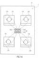
- Figure 2a 1 shows a loudspeaker array 50 having a plurality of type A transducers 52a-52d and a plurality of type B transducers 54a-54d.
- the type A transducers differ in particular in their size, and thus typically, but not necessarily, in their transmissible frequency range from the electroacoustic sound transducers 54a-54d of type B (B for the high-frequency range, eg >1000 Hz or 500Hz; A for the low-frequency range, eg ⁇ 2000 Hz or ⁇ 500Hz).
- the directional characteristics of the type A sound transducers 52a-52d can also be different from the type B sound transducers 54a-54d.
- the transducers 52a-52d and 54a-54b are in Arranged in the form of a line-shaped transducer array 50 and have a total of fewer transducers than in the case of the structure with two parallel arrays of type A and B of the same length. this in Figure 2a
- the array arrangements 50 shown in line form can advantageously be used as arrays for the loudspeaker systems 1, 1' or 1".
- Figures 1a-1d be used.
- FIG. 2b shows a loudspeaker array 60 with the sound transducers 52a-52f (type A) and the sound transducers 54a-54f (type B).
- the sound transducers 52a-52f and 54a-54f are arranged along the line of the array 60 in such a way that an average distance d B between the sound transducers 54a-54f is smaller than an average distance d A between the sound transducers 52a-52f, compare d B ⁇ d A.
- the average distance of the transducer of type B d B is also smaller than the average average distance d AB of all transducers used (cf. Figures 2a and 2b ).
- Such a formation of the mean distance d B in relation to the mean distance d A can be realized by the appropriate sequence of the different sound transducers 52a-52f or 54a-54f.
- a possible form of realization would be the combination of the sound transducers in the form of A, A, B, A, B, B, B, A, B, A, A Figure 2b
- four sound transducers of type B, cf. 54b-54e are arranged in the inner area 60i, which are each framed by a sound transducer of type A (cf. 52c and 52d) on each side, this arrangement in turn being surrounded by a sound transducer of type B (cf. 54a and 54f) is framed.
- This entire sound transducer arrangement is then in turn framed by two sound transducers of type A (cf. 52a, 52b, 52e and 52f) on each side.
- Such a distribution can also be described in other words as logarithmic or at least approximately logarithmic.
- the two system-immanent conditions can be taken into account, namely that for the focused radiation the loudspeaker array 60 should be larger than the wavelength, which is particularly problematic for low-frequency reproduction due to the size of the sound transducers 54a-54h, and that at the same time for error-free reproduction, the distance between adjacent loudspeakers should be smaller than the wavelength, which is particularly problematic for high-frequency reproduction due to the size of the sound transducers 52a-52h.
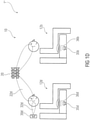
- Figure 2c shows an array 70 having a central B-type transducer 54e surrounded by a total of eight B-type transducers 54a-54i therearound (ie, one on each side).
- a 3 ⁇ 3 field of type B electroacoustic sound converters 54a-54d is generated by the electroacoustic sound converters 54a-54d.
- This 3 ⁇ 3 array of acoustic transducers 54a-54i is located at the center of gravity of the array surface 70 in relation to the entire transducer arrangement 70. This center of gravity is identified by reference number 70i.
- the 3x3 field of sound transducers 54a-54i is in turn surrounded all around by the sound transducers 52a-52h, of type A.
- the average distance between the sound transducers 54a-54i which is referred to as density due to the two-dimensionality, is smaller than the average distance between the sound transducers 52a-52h in the outer region 70a.
- density in the inner area 70i is higher compared to the density of the outer area 70a (defined by the number of sound transducers 52a-52h and 54a-54i per area).
- planar transducer arrangement was only explained in the form of a checkerboard pattern of the transducer array 70, it should be noted that other planar arrangements, e.g. concentric arrangements, with a concentration of transducers of a specific type (B) in a specific area, e.g. in the center (70i) would be conceivable, in which the "sound transducer density" varies over the area.
- the arrangement of the type A/B sound transducers does not necessarily have to be symmetrical either.
- An asymmetrical arrangement ie a slightly offset high-frequency array (cf. 54a-54i) in the center 70i of the low-frequency array (cf. 52a-52h), would also be possible.
- a reduction in artifacts in the radiation function as a result of points of discontinuity can advantageously be achieved.
- the cause of such effects is, for example, edge reflections in tweeters that are placed centrally on the front of the housing.
- the speaker arrays 60 and 70 are the arrays for the embodiment Fig. 1a-d can be used and are compared to the loudspeaker array Figure 2a Advantages in relation to the directional effect, in particular in the case of beamforming for setting the directional characteristic both in the low-frequency and in the high-frequency range, and can also contribute to the avoidance of spatial aliasing effects.
- the concentration of type B transducers in the center 60i and 70i and type A transducers in the outer region 60a and 70a achieved by the transducer arrays 60 and 70 can also be achieved by a two-level transducer arrangement, as described with reference to FIG Fig. 2d is described.
- the Fig. 2d shows a loudspeaker array 80 with a multiplicity of sound transducers 52a-52h (type A), which are arranged linearly (directly) next to one another in a first plane. Furthermore, the sound transducer array 80 comprises a multiplicity of sound transducers 54a-54h (type B), which are also arranged in a line next to one another (adjoining one another). These two sound transducer types 52a-52h and 54a-54h are arranged in two different planes, ie one behind the other or offset or one above the other. Both arrangements of the line arrays have in common that the line on which the sound transducers 52a-52h and 54a-54h are arranged is the same in the sense of being parallel.
- the type B sound transducers which are therefore preferably arranged with a smaller mean distance d B , are positioned in the center of the type A sound transducer arrangement, so that this exemplary embodiment of the loudspeaker array also results in a concentration of Sound transducer for the high-frequency range can be done in the center.
- complex directional characteristics can be assigned to the individual transducers 52a-52h or 54a-54h, for example by sound guides or by the sound transducer itself.
- Another embodiment relates to a combination of multiple line arrays, such as arrays 50 and 60, to form a planar speaker array.
- the line arrays 50 or 60 can have a different number of sound transducers here, so that the line arrays can also have different lengths, for example.
- the sound transducer distances vary per line array, e.g. due to the fact that different types of sound transducers are used.
- each line array can in itself comprise different sound transducer types, the combination of line arrays with one type per line array being preferable.
- An exemplary embodiment is characterized in that two line arrays with acoustic transducer type A enclose three line arrays with acoustic transducer type B. A flat loudspeaker array is then formed in which a specific type of sound transducer is concentrated in the center.
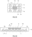
- FIG. 3 shows a loudspeaker array 90, designed here as a combination of eight sound transducers 52a-52h of the same type.
- Each of these sound converters 52a-52h or, to be precise, the membrane 56 of the sound converters 52a-52h is coupled to a sound guide 92a-92h on its emission side.
- These sound guides 92a-92h are funnel-shaped and optionally curved elements, so that the sound outlet openings (see reference number 94) of the sound guide 92a-92h are smaller (in all or at least one dimension) than the sound inlet openings (see reference number 56) on the side of the electroacoustic sound transducers 52a-52h.
- the funnel of the sound guide 92a-92h is designed in such a way that the sound inlet 56 is offset compared to the sound outlet openings 94, with a different offset ratio being used depending on the combination with a sound transducer 52a-52h, so that the total area of the sound outlet openings can be reduced overall .
- the sound outlet openings 94 of the sound guides 92a-92h can be arranged close together with a mean distance d S .
- a very small average distance d S between the sound outlet openings 94 (especially in comparison to the average distance d A ) is achieved, which leads to an improved adjustable directional characteristic (due to the reduction in the sound emission area through the compact Distance d S of the sound outlet openings 94 or due to the reduced virtual sound transducer distance d S ) and better positioning of the array (eg in the vehicle) contributes.
- the combination of the sound guide 92a-92h with one of the loudspeaker arrays 50, 60, 70 or 80 is possible, so that the sound guide can also be used for the exemplary embodiments of the loudspeaker system 1, 1′ or 1′′ from the figs 1a-1d it is a possibility. It is then also possible (as already indicated above) to design the sound guide 92 in such a way that the actual sound transducer array 90 (or also 50, 60, 70, 80), e.g. for reasons of space, can be installed at a suitable point in the car (e.g is housed in the trunk) and the sound guide 92 leads the sound to the corresponding sound outlet point, for example in the roof, which enables space-saving installation.
- the loudspeakers or loudspeaker arrays of the loudspeaker system can also be arranged with a predetermined orientation, for example to the listening positions 12a-12d, so that a directed radiation per sound transducer is possible, which reduces the influence on the room acoustics in the sound zones by the position of the loudspeakers.
- a signal control device can also be created which controls the array 20 or the extended arrays 50, 60, 70, 80, 90 according to the principles described above (cf. mono reproduction of the listening zone 12a-12d or stereo reproduction of the listening zone 12a-12d). controls and thus allows the formation of the corresponding number of highly focused sound radiation beams 22a-22d, 22aL, 22aR.
- the user-specific signals can also be understood to mean the display of other audio information, such as in infotainment signals or telecommunications audio in a specific listening zone, eg the driver's listening zone 12a.
- the speaker system may include a crossover network or a processor configured to add the input signal, if it comprises only listening content (ie content for a person at a respective listening/sitting position), the middle and higher frequencies to the array , For example, in such a way that beam forms can be operated, provide and output the low frequencies to the structure-borne noise transducer of the respective seating position.
- listening content ie content for a person at a respective listening/sitting position
- the middle and higher frequencies For example, in such a way that beam forms can be operated, provide and output the low frequencies to the structure-borne noise transducer of the respective seating position.
- the audio content to be reproduced comprises several parallel contents, e.g.
- the crossover network or the audio processor is designed to provide the middle and higher frequencies of all audio content to be reproduced to the array, specifically in the way that the audio content is reproduced separately for the different listening zones at the different listening positions using beamforming, while the lower frequencies are split off and forwarded separately to the different structure-borne sound transducers in the different seats or listening positions. All in all, this offers the advantage that medium and higher frequencies for the various listening positions are reproduced in a directed manner by means of the array, while the low frequencies are only represented locally via the structure-borne sound transducer.
- the background to this approach is that the low frequencies in particular cannot be directed so well via arrays, so that separating them using beamforming often causes difficulties.
- the structure-borne sound converters which are explicitly assigned to the individual sitting or listening positions, there is no superimposition of the sound signals from these sound converters.
- an average distance (d B ) between the first electro-acoustic sound transducers is smaller than an average distance (d A ) between the second electro-acoustic sound transducers.
- an average density of the first electro-acoustic sound transducer is smaller than an average density of the second electro-acoustic sound transducer.
- the majority of sound exit openings are arranged in such a way that an average distance (d S ) between the sound outlet openings is smaller than a possible average distance (d A ) between the electroacoustic sound transducers arranged next to one another.
- the geometric alignments of the sound transducers 20a-20h in the loudspeaker array 20 shown in the schematic sketches are fictitious and do not necessarily correspond to reality.
- the alignment of the individual sound transducers 20a-20h can deviate accordingly or even vary from position to position (tilted sharply to the first side, tilted to the first side, downwards, tilted to the second side, tilted sharply to the second side).
- a loudspeaker system 1, 1', 1'' for a vehicle can have the following features: a loudspeaker array 20, 50, 60, 70, 80, 90 with a plurality on electroacoustic sound transducers 20a-20h, 52a-52h, 54a-54i which can be controlled individually, so that a user-specific audio signal for different users at different listening positions 12a-12d can be reproduced in a vehicle interior 10 of the vehicle, the loudspeaker array 20, 50, 60, 70, 80, 90 or a sound outlet 94 of the loudspeaker array 20, 50, 60, 70, 80, 90 between at least two of the listening positions 12a -12d is arranged in the vehicle interior 10, the loudspeaker system 1, 1', 1" comprising at least one additional loudspeaker system for each listening position, which has at least one additional loudspeaker (30a, 30d) or an additional loudspeaker array, the additional loudspeaker system having a structure-borne sound loudspeaker 35b, 35
- the loudspeaker system 1, 1', 1'' being designed in order, with the aid of the plurality of electroacoustic sound transducers 20a-20h, 52a-52h, 54a-54i of the loudspeaker array 20, 50, 60, 70, 80, 90 to operate acoustic beam forming to form the sound cones 22a-22d, 22aL, 22aR.
- a distance between the loudspeaker array 20, 50, 60, 70, 80, 90 or the sound outlet 94 of the Loudspeaker arrays 20, 50, 60, 70, 80, 90 and all of the listening positions 12a-12d or a subset of all listening positions 12a-12d with a deviation of +/- 30% be the same.
- the loudspeaker array 20, 50, 60, 70, 80, 90 or the sound outlet 94 of the loudspeaker array 20, 50, 60, 70, 80, 90 be arranged centrally between at least two of the listening positions 12a-12d in the vehicle interior 10.
- the additional loudspeaker system can be closer to the user than the loudspeaker array 20, 50, 60, 70, 80, 90 or the sound outlet 94 of the loudspeaker -Arrays 20, 50, 60, 70, 80, 90.
- the additional speaker system can be installed in a seat assigned to the listening position, in a position assigned to the listening position of the A pillar, the B pillar, the C pillar and /or the headliner and/or be arranged in a headrest assigned to the listening position.
- the additional loudspeaker system in the loudspeaker system 1, 1', 1" can be designed to output a sound 32al, 32d, 36b, 36d in such a way that a large part of the sound 32al, 32d, 36b, 36d with respect to the further one of the listening positions 12a-12d arrives at the corresponding listening position 12a-12d.
- the auxiliary loudspeaker system may be arranged closer to one ear of the user than to the other ear of the user.
- the loudspeaker array 60, 70, 80 can comprise a further plurality of third electroacoustic sound transducers.
- the loudspeaker system 1, 1′, 1′′ can be designed with the aid of the additional loudspeaker system in order to reproduce stereo for each listening position 12a-12d or to reproduce mono with a local level boost.
- the loudspeaker system 1, 1', 1" can be designed to, with the aid of the plurality of electroacoustic sound transducers 20a-20h, 52a-52h, 54a-54i of the Loudspeaker arrays 20, 50, 60, 70, 80, 90 to operate acoustic beam forming to form the sound cones 22a-22d, 22aL, 22aR.
- the loudspeaker system 1, 1′, 1′′ can be designed to 12d to generate at least two sound lobes 22aL, 22aR or a stereo sound lobe; and/or wherein the loudspeaker system 1, 1', 1" can be designed to virtually position sound sources in the room 10 using transfer functions which emulate psychoacoustic effects .
- the beam forming can be based on the direct and/or indirect sound reproduction in relation to the user.
- a sound pressure level and/or a radiation direction per beam assigned to a listening position can be selected such that the sound pressure level at other listening positions 12a-12d after absorption and/or reflection is below a listening threshold.
- the loudspeaker system 1, 1', 1" can be designed to operate beam-forming taking into account a seat adjustment or a head position of the user at the listening position and/or the sound beams 22a-22d, 22aL , 22aR to track depending on the seat adjustment and / or the head position of the user.
- the loudspeaker system 1, 1′, 1′′ can comprise a controller which is designed to individually control the electroacoustic sound transducers 20a-20h, 52a-52h, 54a-54i.
- a loudspeaker array 60, 70, 80 can have the following features: a plurality of first electroacoustic sound transducers 54a-54i arranged on a first line; and a plurality of second electro-acoustic transducers 52a-52h having the first line or a line parallel to the first line, with an average distance d B between the first electroacoustic sound transducers 54a-54i being smaller than an average distance d A between the second electroacoustic sound transducers 54a-54i.
- a loudspeaker array 70 can have the following features with reference to a previous aspect: a plurality of first electroacoustic sound transducers 54a-54i, which are arranged in a first planar region 70i; and a plurality of second electro-acoustic sound transducers 52a-24h arranged in the first planar area 70a, wherein an average density of the first electro-acoustic sound transducers 54a-54i is smaller than an average density of the second electro-acoustic sound transducers 52a-52h.
- At least two of the first electro-acoustic transducers 54a-54i can be framed by two of the second electro-acoustic transducers 52a-52h.
- the first electroacoustic sound transducers 54a-54i can be designed in the loudspeaker array 20, 50, 60, 70, 80, 90 to define a first frequency range by a first center frequency reproduce, and the second electroacoustic sound transducer 52a-52h be designed to reproduce a second frequency range defined by a second center frequency, the first center frequency being higher than the second center frequency.
- a loudspeaker array 90 can have the following features: a plurality of electroacoustic sound transducers 52a-52h, which are coupled to first sound guides 92a-92h for sound output in a first area 56, each sound guide 92a-92h including a sound outlet opening 94 , the plurality of sound outlet openings 94 being arranged such that an average distance d S between the sound outlet openings 94 is smaller than a possible average distance d A between the electroacoustic sound transducers 52a-52h arranged next to one another.
Description
Ausführungsbeispiele der vorliegenden Erfindung beziehen sich auf ein Lautsprechersystem für ein Fahrzeug, insbesondere mit einem Lautsprecher-Array, allgemein auf Lautsprecher-Arrays mit einer Mehrzahl an elektroakustischen Schallwandlern in unterschiedlichen Anordnungskonfigurationen und auf ein Lautsprecher-Array mit Schallführung.Embodiments of the present invention relate to a loudspeaker system for a vehicle, in particular with a loudspeaker array, generally to loudspeaker arrays with a plurality of electroacoustic sound transducers in different arrangement configurations and to a loudspeaker array with sound guidance.
Zukünftige Infotainment-Systeme in Fahrzeugen und die damit verbundenen Lautsprechersysteme in Fahrzeugen müssen anspruchsvollen Aufgaben in komplexen Verkehrsszenarien gerecht werden. Dazu wird eine absolut zuverlässige Funktion vorausgesetzt, wobei Gefahren in beliebigen Fahrsituationen für den Fahrer, z.B. durch Fehlfunktion, ausgeschlossen werden müssen. Hierbei spielen Kommunikationsanforderungen und schnelle Informationsbereitstellung sowie ungestörte Audiowiedergabe eine wesentliche Rolle. Dabei sind als Störsignale nicht nur Fahrzeuggeräusche zu verstehen, sondern auch paralleles Konsumieren von unterschiedlichen Audio-Inhalten, wie etwa beim gleichzeitigen Telefonieren und Konsumieren von Medieninhalte aus Sicht mehrerer Passagiere. Derartige Herausforderungen bedingen Systemeigenschaften, die eine individuelle Beschallung auf begrenzte Hörgebiete, sogenannte Schall- oder Hörzonen ermöglichen.Future infotainment systems in vehicles and the associated loudspeaker systems in vehicles must be able to cope with demanding tasks in complex traffic scenarios. This requires an absolutely reliable function, whereby dangers in any driving situation for the driver, e.g. due to malfunctions, must be ruled out. Here, communication requirements and fast provision of information as well as undisturbed audio playback play an important role. Interfering signals are not just vehicle noises, but also parallel consumption of different audio content, such as simultaneous phone calls and consumption of media content from the perspective of several passengers. Such challenges require system properties that enable individual sound reinforcement to limited listening areas, so-called sound or listening zones.
Zur Realisierung dieser Systeme sind typischerweise neben den elektroakustischen Komponenten, effiziente Algorithmen zur Störschallunterdrückung und eine leistungsfähige Datenkommunikation zur Regelung des adaptiven Systems erforderlich.In addition to the electro-acoustic components, the realization of these systems typically requires efficient algorithms for noise suppression and powerful data communication for controlling the adaptive system.
Ausgehend von dieser Problemstellung gibt es bereits einige auf dem Markt eingesetzte bzw. zumindest teilweise erprobte Konzepte. Ein Beispiel ist die personalisierte Beschallung (mittels Schallzonen) durch Verwendung von Lautsprechern in unmittelbarer Nähe zu den Ohren des Hörers in der jeweiligen Schallzone, z.B. durch Lautsprecherintegration in die entsprechenden Kopfstützen des jeweiligen Autositzes pro Hörzone. Ein derartiges System mit in Gruppen unterteilte Lautsprecher ist in der Patentschrift
Ein zweiter Stand-der-Technik-Ansatz betrifft die personalisierten Schallzonen, welche unter Verwendung von Ultraschalltechnik erzeugt werden können. Hörschall wird auf Ultraschallträger moduliert und hochfokussiert auf die Hörzonen abgestrahlt. Grundvoraussetzung dieses Modulationsprinzips ist die Abstrahlung von sehr hohen Ultraschallpegeln, z.B. größer 130 dB. Der Vorteil dieses Ansatzes liegt darin, dass der Ultraschall infolge der günstigen Verhältnisse aus Wellenlänge zu der Größe der aktiven "Abstrahlfläche", definiert durch die Lautsprecher-Größe bzw. die Lautsprecher-Array-Größe, stärker fokussiert abgestrahlt wird als Frequenzen des Hörfrequenzbereichs. Damit ist eine höhere akustische Trennung der Schallzonen bei gleicher Größe der verwendeten Lautsprechertechnik möglich. Der Nachteil dieses Ansatzes ist nicht nur, dass Ultraschall ab bestimmten Leistungspegeln gesundheitsschädigend sein kann (vgl. hierzu Einsatz von Ultraschall im medizinischen Bereich zur Zerstörung von Nierensteinen), sondern auch, dass es bei der Verwendung von Ultraschall zu starken Reflexionen im Fahrzeuginnenraum kommt, die sich nachteilig auf die akustische Kanaltrennung auswirken. Ferner bedingt der Ultraschalleinsatz einen hohen Leistungsbedarf, was gleichbedeutend mit einer geringen Energieeffizienz ist. Hinzu kommt ein stark nichtlineares Übertragungsverhalten aufgrund des Demodulationsprinzips, was eine geringe Klangqualität nach sich zieht, die in der Regel nur für Sprachwiedergabe ausreicht.A second prior art approach relates to the personalized sound zones that can be created using ultrasonic technology. Audible sound is modulated onto ultrasonic carriers and radiated in a highly focused manner onto the auditory zones. The basic prerequisite for this modulation principle is the emission of very high ultrasonic levels, e.g. greater than 130 dB. The advantage of this approach is that due to the favorable relationship between the wavelength and the size of the active "radiating surface", defined by the size of the loudspeaker or the size of the loudspeaker array, the ultrasound is radiated in a more focused manner than frequencies in the audio frequency range. This enables a higher acoustic separation of the sound zones with the same size of loudspeaker technology used. The disadvantage of this approach is not only that ultrasound can be harmful to health from a certain power level (cf. use of ultrasound in the medical field to destroy kidney stones), but also that the use of ultrasound leads to strong reflections in the vehicle interior, which adversely affect acoustic channel separation. Furthermore, the use of ultrasound requires a high level of power, which is synonymous with low energy efficiency. In addition, there is a strongly non-linear transmission behavior due to the demodulation principle, which results in a low sound quality that is usually only sufficient for speech reproduction.
Ein weiterer Stand-der-Technik-Ansatz basiert auf dem sogenannten Beamforming. Hierzu werden mehrere Lautsprecher verwendet, die z.B. im Fahrzeug verteilte und/oder zu einem Lautsprecher-Array gruppiert sind. Durch die gezielte Ansteuerung jedes Lautsprechers wird eine gerichtete Schallabstrahlung, z.B. für individuelle Schallzonen, erzielt. Im Zusammenhang hiermit sei beispielsweise auf die Patentschrift
Des Weiteren offenbart die Patentschrift
Die
Aufgabe der vorliegenden Erfindung ist es, ein Konzept für ein Lautsprechersystem, insbesondere für ein Fahrzeug-Lautsprechersystem, zu schaffen, das die oben beschriebenen Nachteile vermeidet und somit qualitativ hochwertige Raumklangerzeugung mit guter Kanaltrennung ermöglicht. Insbesondere ist es Ziel der Erfindung, eine platzsparende Installation zu ermöglichen.The object of the present invention is to create a concept for a loudspeaker system, in particular for a vehicle loudspeaker system, which avoids the disadvantages described above and thus enables high-quality surround sound generation with good channel separation. In particular, the aim of the invention is to enable space-saving installation.
Die Aufgabe wird durch die Gegenstände der unabhängigen Patentansprüche gelöst. Weitere Ausführungsbeispiele sind in den abhängigen Ansprüchen definiert.The object is solved by the subject matter of the independent patent claims. Further embodiments are defined in the dependent claims.
Ein Ausführungsbeispiel umfasst ein Lautsprechersystem für ein Fahrzeug mit einem Lautsprecher-Array. Das Lautsprecher-Array umfasst eine Mehrzahl elektroakustischer Schallwandler, die individuell ansteuerbar sind, so dass über die Mehrzahl der elektroakustischen Schallwandler ein nutzerspezifisches Audiosignal für verschiedene Nutzer an unterschiedlichen Hörpositionen in einem Fahrzeuginnenraum des Fahrzeugs wiedergebbar ist. Das Lautsprecher-Array oder im Fall von eingesetzten Schallführungen ein Schallauslass des Lautsprecher-Arrays ist hierbei insbesondere zwischen zumindest zwei der Hörpositionen in dem Fahrzeuginnenraum, also z.B. zwischen dem Fahrer und dem Beifahrersitz, angeordnet.One embodiment includes a speaker system for a vehicle having a speaker array. The loudspeaker array includes a plurality of electroacoustic sound converters that can be controlled individually, so that a user-specific audio signal for different users at different listening positions in a vehicle interior of the vehicle can be reproduced via the plurality of electroacoustic sound converters. The speaker array or in the case of deployed Sound guides a sound outlet of the speaker array is in particular between at least two of the listening positions in the vehicle interior, for example between the driver and the passenger seat, are arranged.
Den Ausführungsbeispielen dieses Aspekts liegt also die Erkennung zugrunde, dass ein Lautsprechersystem für ein Fahrzeug insbesondere hinsichtlich Kanaltrennung, z.B. bei Wiedergabe unterschiedlicher Audio-Inhalt an den unterschiedlichen Hörpositionen, dadurch verbessert werden kann, dass ein Lautsprecher-Array zentral im Sinne von mittig bezogen auf alle oder die relevanten Hörpositionen angeordnet ist. Das eingesetzte Lautsprecher-Array kann für jeden Hörplatz (oder jeden relevanten Hörplatz) eine separate Schallkeule bzw. z.B. bei Stereo mehrere separate Schallkeulen pro Zone aufbauen. Durch die mittige Anordnung des Lautsprecher-Arrays, z.B. am Dachhimmel zwischen den Sitzen, wird erreicht, dass das Lautsprecher-Array von jedem relevanten Hörplatz ungefähr gleichweit entfernt ist, so dass jede Schallkeule ähnliche Ausdehnung aufweist und vor allem dass die Schallkeulen in Bezug auf ihre Richtung auch gegenläufig orientiert sind, was in Hinblick auf die Kanaltrennung insbesondere bei nutzerspezifischer Audiowiedergabe optimal ist.The exemplary embodiments of this aspect are therefore based on the recognition that a speaker system for a vehicle, in particular with regard to channel separation, e.g. when playing different audio content at the different listening positions, can be improved by placing a speaker array centrally in the sense of centered on all or the relevant listening positions. The loudspeaker array used can set up a separate sound cone for each listening position (or each relevant listening position) or, for example, in the case of stereo, several separate sound cones per zone. By arranging the loudspeaker array in the middle, e.g Direction are also oriented in opposite directions, which is optimal in terms of channel separation, especially for user-specific audio playback.
Wie oben bereits angedeutet, wäre eine bevorzugte Positionierung des Lautsprecher-Arrays entsprechend den Ausführungsbeispielen im Dachhimmel des Fahrzeugs, in der Mittelkonsole, in dem Armaturenbrett oder in der Hutablage, wobei entsprechend weiterer Ausführungsbeispiele insbesondere wichtig ist, dass ein Abstand zwischen dem Array und den Hörpositionen bzw. zumindest den relevanten Hörpositionen (Teilmenge aller Hörpositionen) im Wesentlichen, d.h. also mit einem abweichenden +/- 30% gleich ist.As already indicated above, a preferred positioning of the loudspeaker array according to the exemplary embodiments would be in the roof liner of the vehicle, in the center console, in the dashboard or in the parcel shelf, it being particularly important according to further exemplary embodiments that there is a distance between the array and the listening positions or at least the relevant listening positions (subset of all listening positions) is essentially the same, ie with a deviating +/- 30%.
Je Hörposition kann entsprechend weiteren Ausführungsbeispielen zumindest ein Zusatzlautsprecher, wie z.B. der üblicherweise vorhandene Lautsprecher in der Tür bzw. dem Spiegeldreieck und/oder ein anders positionierter Zusatzlautsprecher vorgesehen sein. Der Zusatzlautsprecher kann auch als Körperschallwandler ausgeführt sein. Der Zusatzlautsprecher ist bevorzugt näher am Nutzer angeordnet als das Lautsprecher-Array. Durch eine derartige dichte Anordnung ist es möglich, dass der von dem Zusatzlautsprecher abgestrahlte Schall in Bezug auf die anderen Hörpositionen nahezu zu vernachlässigen ist, da hier mit wesentlich geringeren Schallpegeln und großen Pegeldifferenz infolge großem Unterschied im Hörabstand gearbeitet werden kann. Durch diesen Zusatzlautsprecher ist es möglich, je Hörposition Stereo, aber auch Mono mit lokaler Pegelanhebung oder Frequenzerweiterung (z.B. Tiefton) zu erzeugen.According to further exemplary embodiments, at least one additional loudspeaker can be provided for each listening position, for example the loudspeaker usually present in the door or the mirror triangle and/or a differently positioned additional loudspeaker. The additional loudspeaker can also be designed as a structure-borne noise converter. The additional loudspeaker is preferably arranged closer to the user than the loudspeaker array. Such a dense arrangement makes it possible for the sound radiated by the additional loudspeaker to be almost negligible in relation to the other listening positions, since one can work here with significantly lower sound levels and large level differences due to the large difference in the listening distance. This additional speaker makes it possible to produce stereo, but also mono with local level boosting or frequency expansion (e.g. bass) for each listening position.
Stereo kann auch unter Zuhilfenahme der Mehrzahl der elektroakustischen Schallwandlern und des Lautsprecher-Arrays basierend auf der Technik des akustischen Beamformings erzeugt werden. Hierbei werden dann beispielsweise pro Hörposition mindestens zwei Beams (Schallkeulen) oder auch ein Stereo-Beam erzeugt. In diesem Zusammenhang muss auch erwähnt werden, dass es denkbar wäre, dass unter Zuhilfenahme von Übertragungsfunktionen, welche psychoakustischen Effekte emulieren, die zu erzeugenden Schallquellen virtuell im Raum positioniert werden. Vorteilhaft bei der Positionierung der Quellen mittels Beamforming wäre es entsprechend zusätzlichen Ausführungsbeispielen, dass die Beams unter Berücksichtigung der Sitzeinstellung bzw. der Kopfposition des Hörers nachgeführt werden, so dass unabhängig von der Sitzposition ein gleichbleibend guter Wiedergabeeindruck entsteht.Stereo can also be generated using the majority of the electroacoustic sound transducers and the loudspeaker array based on the technique of acoustic beamforming. In this case, for example, at least two beams (sound cones) or a stereo beam are generated per listening position. In this context, it must also be mentioned that it would be conceivable for the sound sources to be generated to be positioned virtually in space with the aid of transfer functions that emulate psychoacoustic effects. According to additional exemplary embodiments, it would be advantageous when positioning the sources by means of beamforming for the beams to be tracked taking into account the seating position or the head position of the listener, so that a consistently good reproduction impression is produced regardless of the seating position.
Entsprechend einem weiteren Ausführungsbeispiel umfasst das Lautsprechersystem auf einen Signalprozessor, der beispielsweise zum Beamforming den elektroakustischen Schallwandler und/oder den oder die Zusatzlautsprecher individuell ansteuert.According to a further exemplary embodiment, the loudspeaker system includes a signal processor which, for example for beamforming, individually controls the electroacoustic sound converter and/or the additional loudspeaker or loudspeakers.
Die Erfindung schafft ein Lautsprecher-Array mit einer Mehrzahl an elektroakustischen Schallwandlern, die an ihrer Schallabstrahlfläche mit Schallführungen zur Schallausgabe bzw. zur Schalllenkung gekoppelt sind, wobei jede Schallführung eine Schallaustrittsöffnung umfasst. Die Mehrzahl der Schallaustrittsöffnungen ist so angeordnet, dass ein mittlerer Abstand zwischen den Schallaustrittsöffnungen kleiner ist als ein (möglicher) mittlerer Abstand zwischen den nebeneinander angeordneten elektroakustischen Schallwandlern.The invention creates a loudspeaker array with a plurality of electroacoustic sound transducers which are coupled on their sound emission surface with sound guides for sound output or for sound guidance, each sound guide comprising a sound exit opening. The majority of the sound outlet openings are arranged in such a way that an average distance between the sound outlet openings is smaller than a (possible) average distance between the electroacoustic sound transducers arranged next to one another.
Diesem liegt die Erkenntnis zugrunde, dass bei Lautsprecher-Arrays eine kompakte Verteilung der einzelnen Schallquellen, insbesondere in Hinblick auf die selektive Schallfokussierung bei der Schallabstrahlung zu bevorzugen ist. Um eine kompakte Verteilung auch bei Arrays mit großer Ausdehnung, z.B. infolge von großen Schallwandlern, zu erreichen, werden erfindungsgemäß (für diesen dritten Aspekt) trichterförmige Schallführungen, welche jeweils mit einem elektroakustischen Schallwandler gekoppelt sind, eingesetzt. Dabei sind die Schallaustrittsöffnungen der Schallführungen kleiner als die Schalleinlassöffnungen der Schallführungen, so dass die Schallaustrittsöffnungen als kompaktes Feld arrangiert werden können. Somit kann die Richtungscharakteristik für ein Array, welches mit einer Vielzahl von Schallführungen gekoppelt wird, verbessert werden.This is based on the finding that, in the case of loudspeaker arrays, a compact distribution of the individual sound sources is to be preferred, in particular with regard to the selective focussing of the sound in the sound emission. In order to achieve a compact distribution even in arrays with large dimensions, e.g. as a result of large sound transducers, according to the invention (for this third aspect) funnel-shaped sound guides, which are each coupled to an electroacoustic sound transducer, are used. The sound exit openings of the sound guides are smaller than the sound inlet openings of the sound guides, so that the sound exit openings can be arranged as a compact field. Thus, the directivity for an array coupled to a plurality of sound guides can be improved.
Ausführungsbeispiele der vorliegenden Erfindung werden nachfolgend anhand der beiliegenden Zeichnungen erläutert. Es zeigen:
- Fig. 1a
- ein exemplarisches Schaubild einer Anordnung eines Lautsprecher-Arrays in einem Fahrzeug gemäß einem ersten Ausführungsbeispiel (Mono) ;
- Fig. 1b
- ein schematisches Schaubild einer Anordnung in einem Fahrzeug gemäß einem weiteren Ausführungsbeispiels (teilweise Stereo) ;
- Fig. 1c,d
- schematische Schaubilder von der Anordnung eines Lautsprecher-Arrays in Kombination mit Zusatzschallwandlern in einem Fahrzeug gemäß weiteren Ausführungsbeispielen (teilweise Stereo);
- Fig. 2a
- ein schematisches Schaubild eines Lautsprecher-Arrays mit Schallwandlern unterschiedlichen Typs für das Lautsprechersystem gemäß den Ausführungsbeispielen aus
Figs.1a-1d ; - Fig. 2b
- ein schematisches Schaubild eines Linienförmigen Lautsprecher-Arrays mit Schallwandlern unterschiedlichen Typs gemäß einem Ausführungsbeispiel ;
- Fig. 2c
- ein schematisches Schaubild eines Lautsprecher-Arrays mit flächig angeordneten Schallwandlern unterschiedlichen Typs gemäß einem weiteren Ausführungsbeispiel;
- Fig. 2d
- ein Schaubild eines Lautsprecher-Arrays mit Schallwandlern unterschiedlichen Typs gemäß einem zusätzlichen Ausführungsbeispiel; und
- Fig. 3
- ein schematisches Schaubild eines Lautsprecher-Arrays mit einer Vielzahl an Schallführungen gemäß einem Ausführungsbeispiel der Erfindung.
- Fig. 1a
- an exemplary diagram of an arrangement of a speaker array in a vehicle according to a first embodiment (mono);
- Fig. 1b
- a schematic diagram of an arrangement in a vehicle according to a further exemplary embodiment (partially stereo);
- Fig. 1c, d
- schematic diagrams of the arrangement of a loudspeaker array in combination with additional sound transducers in a vehicle according to further exemplary embodiments (partially stereo);
- Figure 2a
- 1 shows a schematic diagram of a loudspeaker array with sound transducers of different types for the loudspeaker system according to the exemplary embodiments
Figs.1a-1d ; - Figure 2b
- a schematic diagram of a linear loudspeaker array with sound transducers of different types according to an embodiment;
- Figure 2c
- a schematic diagram of a loudspeaker array with two-dimensionally arranged sound transducers of different types according to a further exemplary embodiment;
- Fig. 2d
- a diagram of a loudspeaker array with sound transducers of different types according to an additional embodiment; and
- 3
- a schematic diagram of a loudspeaker array with a plurality of sound guides according to an embodiment of the invention.
Bevor nachfolgend Ausführungsbeispiele der vorliegenden Erfindung anhand der Figuren im Detail erläutert werden, sei darauf hingewiesen, dass gleiche Elemente oder Strukturen mit gleichen Bezugszeichen versehen sind, so dass die Beschreibung der austauschbar bzw. aufeinander anwendbar ist.Before exemplary embodiments of the present invention are explained in detail below with reference to the figures, it should be noted that the same elements or structures are provided with the same reference symbols, so that the description of the figures is interchangeable or applicable to one another.
Wie hier illustriert, ist das Array 20 in Bezug auf den Fahrzeuginnenraum 10 relativ zentral angeordnet, was zur Folge hat, dass das Array 20 zumindest zwischen zwei Hörpositionen (Teilmenge aller Hörpositionen 12a-12d), hier sogar zwischen den vier Hörpositionen 12a-12d angeordnet ist. Als mögliche Bauräume für das Lautsprecher-Array ist hier beispielsweise der Dachhimmel, die Mittelkonsole, aber auch alternativer Weise das Armaturenbrett bzw. die Hutablage zu nennen. Allgemein gesprochen heißt das, dass das Lautsprecher-Array 20 oberhalb oder unterhalb oder sogar auf Höhe der Hörzonen 12a-12d bzw. der Ohrhöhe des Hörers installiert sein kann. Der Vollständigkeit halber sei angemerkt, dass sich der Begriff zentral auf alle Hörzonen 12a-12d oder zumindest auf eine Teilmenge der Hörzonen 12a-12d, z.B. die Hörzone 12a und 12b, bezieht. Nachfolgend wird auf die Funktionsweise des so realisierten Lautsprechersystems für das Fahrzeug eingegangen.As illustrated here, the
In dem dargestellten Beispiel wird durch das Lautsprecher-Array je Hörposition 12a-12d eine Schallkeule 22a-22d, die bevorzugter Weise auf die Hörzonen 12a-12d ausgerichtet sind bzw. zumindest diesen zugeordnet sind, ausgebildet. Die Ausbildung dieser Schallkeulen 22a-22d erfolgt dadurch, dass die Schallwandler 20a-20h des Lautsprecher-Arrays 20 unterschiedlich angesteuert werden, beispielsweise unter Berücksichtigung von sogenannten Beamforming-Algorithmen, die auch die Abstrahlcharakteristik der Einzelwandler 20a-20h sowie die raumakustischen Einflüsse einbeziehen können. Im Zusammenhang mit dieser Signalverarbeitung sei auf die Grundlagen der Lehre der Wellenfeldsynthese verwiesen, die größtenteils die Basis für das hier durchgeführte Beamforming bietet. D.h. also, dass das Lautsprecher-Array 20 ausgebildet ist, um je Hörplatz 12a-12d eine separate Schallkeule 22a-22d aufzubauen, wobei aufgrund der zentralen Anordnung jede Schallkeule 22a-22d in Bezug auf ihre Ausrichtung gegenläufig (von der Mitte zu den Hörplätzen12a-12d) orientiert ist. Zusätzlich ist (infolge der zentralen Anordnung) das Lautsprecher-Array 20 von jedem Hörplatz 12a-12d ungefähr gleichweit entfernt, so dass jede Schallkeule 22a-22d ähnliche Ausprägungen (z.B. Ausdehnung und Pegel) aufweist. . Diese zwei Eigenschaften tragen maßgeblich zu der erreichten Kanaltrennung zwischen den Kanälen 22a-22d bei. Ein Vorteil der mittels dem Beamforming erzeugten Schallkeulen 22a-22d liegt darin, dass die Kanaltrennung so gut ist, dass nutzerspezifische Audiosignale für die Hörzonen 12a-12c erzeugt werden können. Infolgedessen kann in den unterschiedlichen Hörzonen 12a-12d nicht nur ein unterschiedliches Audiosignal im Sinne von Lautheit sondern sogar unterschiedliche Audioinhalte wiedergegeben werden. Zusätzlich wäre es auch denkbar, dass in einer der Schallzonen 12a-12d gezielt Stille durch Schallauslöschung generiert werden kann.In the example shown, the loudspeaker array forms a
Bezug nehmend auf das Ausführungsbeispiel aus
Entsprechend Ausführungsbeispielen kann anstelle des gesamten Lautsprecher-Arrays 20 auch ein Schallauslass einer Schallführung (vgl.
Durch derartig angeordnete Lautsprecher-Arrays ist es auch möglich, Stereo oder sogar 3D-Raumklang je Hörposition 12a-12d zu erzeugen, wie Bezug nehmend auf
Wie in
Entsprechend weiteren Ausführungsbeispielen wäre es auch denkbar, dass bei der Ausrichtung der Schallkeulen 22aL, 22aR, 22b, 22c und 22d eine Berücksichtigung von Schallreflexionen (z.B. über Glasflächen) oder Schallabsorption erfolgt. Also wird im Vorfeld berücksichtigt, inwieweit direkte Schallwiedergabe und/oder indirekte Schallwiedergabe, also unter Einbeziehung von Wandreflexionen oder auch von optionalen Schallführungen, zum Einsatz kommt.According to further exemplary embodiments, it would also be conceivable for sound reflections (e.g. via glass surfaces) or sound absorption to be taken into account when aligning the sound cones 22aL, 22aR, 22b, 22c and 22d. So it is taken into account in advance to what extent direct sound reproduction and/or indirect sound reproduction, i.e. including wall reflections or optional sound guides, is used.
Entsprechend wiederum weiteren Ausführungsbeispielen wäre denkbar, dass die Schallkeulen 22aL, 22aR, 22b, 22c und 22d in Abhängigkeit von der Sitzposition, die die Hörposition 12a, 12b, 12c und 12d definieren, ausgerichtet werden. Hierbei wäre beispielsweise eine informatorische Kopplung des Lautsprechersystems an die (elektrische) Sitzeinstellung denkbar.According to further exemplary embodiments, it would be conceivable that the sound cones 22aL, 22aR, 22b, 22c and 22d, depending on the seating position, which is the
Ein weiteres Ausführungsbeispiel für das Lautsprechersystem ist in
Wie hier dargestellt, erzeugt der Zusatzlautsprecher 30a eine Schallkeule 32aL, die dem einen (linken) Ohr des Hörers eine Hörposition 12a zugeordnet ist, während das andere (rechte) Ohr durch die Schallkeule 22aR (erzeugt durch das Lautsprecher-Array 20) beschallt wird. Somit ist es in dem dargestellten Ausführungsbeispiel möglich, Stereo an dem Hörplatz 12a zu erzeugen. Die Verwendung des Zusatzlautsprechers 30a ist nicht auf Stereo beschränkt, so kann der Zusatzlautsprecher 30a allgemein zur Unterstützung der Beschallung an dem Hörplatz 12a (Mono mit Pegelanhebung) dienen. Hierbei ist es vorteilhaft, dass der Zusatzlautsprecher 30a nah an dem Hörplatz positioniert wird, so dass die Gesetzmäßigkeiten des Schallpegelabfalls mit der Entfernung ausgenutzt werden, was dazu führt, dass der Schallpegel des Zusatzlautsprechers 30a in der zugehörigen Hörzone 12a lauter ist als in den fremden Hörzonen 12b-12d. Dies trägt vor allem zur erhöhten akustischen Trennung der Schallzonen 12a-12d bei. Allgemein sind die Vorteile eines des Zusatzlautsprechers 30a darin zu sehen, dass die Klangqualität und der Raumeindruck für die zugehörige Schallzone durch Ausnutzung von psychoakustischen Effekten verbessert werden. Allgemein sei festgestellt, dass durch die Anordnung von Schallwandlern 20 bzw. 30a möglichst nahe an der Hörposition (hier 12a), vgl. z.B. Schallwandler 20 und 30a in Bezug auf die Hörposition 12a, der Anteil an Direktschall zunimmt, so dass Reflexionen weiterstgehend verdeckt werden bzw. vernachlässigbar sind.As shown here, the
Entsprechend weiteren Ausführungsbeispielen ist es, wie auch hier in
Auch wenn das bzgl.
Bezug nehmend auf
Wie in
In dieser Schallwandleranordnung des Arrays 60 kann sichergestellt werden, dass im Innenbereich (vgl. Bereich markiert mit dem Bezugszeichen 60i) eine hohe Dichte an Schallwandlern des Typs B, die im Hochtonbereich arbeiten und sich tendenziell durch eine gute Einstellung der Abstrahlcharakteristik auszeichnen, vorliegt. Dies gilt insbesondere im Vergleich zu dem Außenbereich bzw. den Außenbereichen 60a. Durch eine derartige Anordnung kann den zwei systemimmanenten Bedingungen Rechnung getragen werden, nämlich dass für die fokussierten Abstrahlung das Lautsprecher-Array 60 größer sein sollte als die Wellenlänge, was insbesondere für die Tieftonwiedergabe aufgrund der Größe der Schallwandler 54a-54h problematisch ist, und dass gleichzeitig für die fehlerfreie Reproduktion der Abstand benachbarter Lautsprecher kleiner als die Wellenlänge sein sollte, was insbesondere für die Hochtonwiedergabe aufgrund der Größe der Schallwandler 52a-52h problematisch ist..In this sound transducer arrangement of
Das in
Bei diesem Ausführungsbeispiel ist der mittlere Abstand der Schallwandler 54a-54i, der aufgrund der Zweidimensionalität als Dichte bezeichnet wird, kleiner als der mittlere Abstand der Schallwandler 52a-52h im Außenbereich 70a. Das heißt also, dass die Dichte im Innenbereich 70i im Vergleich zur Dichte des Außenbereichs 70a (definiert durch die Anzahl an Schallwandlern 52a-52h und 54a-54i pro Fläche) höher ist. Auch bei dieser Flächenanordnung kann also ein kleiner Schallwandler-Abstand zu hochfokussierten Abstrahlungen bei den Schallwandlern 54a-54i für die hohen Frequenzbereiche und ein bauartbedingter größerer Schallwandler-Abstand (zur fokussierten Abstrahlung) für die tieferen Frequenzbereiche (vgl. Schallwandler 52a-52h) erreicht werden.In this exemplary embodiment, the average distance between the
Auch wenn die flächige Schallwandleranordnung nur in Form eines Schachbrettmusters des Schallwandler-Arrays 70 erläutert wurde, sei darauf hingewiesen, dass auch andere flächige Anordnungen, z.B. konzentrische Anordnungen, mit Konzentration von Schallwandlern eines bestimmten Typs (B) in einem bestimmten Bereich, z.B. im Zentrum (70i) denkbar wären, bei welchen die "Schallwandlerdichte" über die Fläche variiert. Die Anordnung der Schallwandler des Typs A/B muss auch nicht zwingend symmetrisch sein. So wäre auch eine asymmetrische Anordnungen, also leicht versetztes Hochton-Array (vgl. 54a-54i) im Zentrum 70i des Tiefton-Arrays (vgl. 52a-52h) möglich. Vorteilhafter Weise kann so eine Reduzierung von Artefakten in der Abstrahlfunktion infolge von Unstetigkeitsstellen erreicht werden. Ursache für solche Effekte ist beispielsweise Kantenreflexion bei Hochtönern, welche zentral auf Gehäusefront platziert sind.Even if the planar transducer arrangement was only explained in the form of a checkerboard pattern of the
Die Lautsprecher-Arrays 60 und 70 sind als Arrays für das Ausführungsbeispiel aus
Die durch die Schallwandler-Arrays 60 und 70 erreichte Konzentrierung von Schallwandlern des Typs B im Zentrum 60i und 70i und von Schallwandlern des Typs A im Außenbereich 60a und 70a kann auch durch eine Schallwandleranordnung mit zwei Ebenen erreicht werden, wie es Bezug nehmend auf
Die
Es sei angemerkt, dass es für dieses Ausführungsbeispiel unerheblich ist, ob die Schallwandler des Typs A in der ersten oder zweiten Ebene angeordnet sind und umgekehrt auch, ob die Schallwandler des Typs B in der ersten oder zweiten Ebene angeordnet sind.It should be noted that it is irrelevant for this exemplary embodiment whether the sound transducers of type A are arranged in the first or second plane and, conversely, whether the sound transducers of type B are arranged in the first or second plane.
Optionaler Weise ist es jedoch wichtig, dass die Schallwandler des Typs B, die also bevorzugt mit einem geringeren mittleren Abstand dB angeordnet werden, im Zentrum der Schallwandleranordnung des Typs A positioniert werden, so dass auch durch dieses Ausführungsbeispiel des Lautsprecher-Arrays eine Konzentration von Schallwandler für den Hochfrequenzbereich im Zentrum erfolgen kann.Optionally, however, it is important that the type B sound transducers, which are therefore preferably arranged with a smaller mean distance d B , are positioned in the center of the type A sound transducer arrangement, so that this exemplary embodiment of the loudspeaker array also results in a concentration of Sound transducer for the high-frequency range can be done in the center.
Bei weiteren Ausführungsbeispielen wäre es auch möglich, dass weitere Schallwandler, z.B. Schallwandler des Typs C in einer dritten Ebene angeordnet werden.In further exemplary embodiments, it would also be possible for further sound transducers, e.g. type C sound transducers, to be arranged in a third plane.
Bezug nehmend auf die Lautsprecheranordnungen aus den
Ein weiteres Ausführungsbeispiel bezieht sich auf eine Kombination aus mehreren Linienarrays, wie z.B. die Arrays 50 und 60, so dass ein flächiges Lautsprecher-Array gebildet wird. Die Linienarrays 50 oder 60 können hier eine unterschiedliche Anzahl an Schallwandlern aufweisen, so dass sich beispielsweise auch unterschiedliche Längen der Linienarrays ergeben. Ferner wäre es auch denkbar, dass die Schallwandlerabstände je Linienarray, z.B. aufgrund dessen, dass unterschiedliche Schallwandlertypen eingesetzt werden, variieren. Entsprechend weiteren Ausführungsbeispielen kann jedes Linienarray in sich unterschiedliche Schallwandlertypen umfassen, wobei die Kombination von Linienarrays mit je einem Typ pro Linienarray zu bevorzugen ist. Ein Ausführungsbeispiel ist dadurch gekennzeichnet, dass zwei Linienarrays mit dem Schallwandlertyp A drei Linienarrays mit dem Schallwandlertyp B einschließen. So wird dann ein flächiges Lautsprecher-Array gebildet, bei dem ein bestimmter Typ an Schallwandlern im Zentrum konzentriert ist.Another embodiment relates to a combination of multiple line arrays, such as
Bezug nehmend auf
Hierdurch können die Schallaustrittsöffnungen 94 der Schallführungen 92a-92h dicht nebeneinander mit einem mittleren Abstand dS angeordnet werden. Infolgedessen wird trotz eines flächig groß ausgedehnten Lautsprecher-Arrays 90 einen sehr kleinen mittleren Abstand dS zwischen den Schallaustrittsöffnungen 94 (insbesondere im Vergleich zu dem mittleren Abstand dA) erreicht, was zu einer verbessert einstellbaren Richtungscharakteristik (aufgrund der Verringerung der Schallabstrahlfläche durch den kompakten Abstand dS der Schallaustrittsöffnungen 94 bzw. aufgrund des reduzierten virtuellen Schallwandler-Abstands dS) und besseren Positionierbarkeit der Arrays (z.B. im Fahrzeug) beitragt.As a result, the
Die Kombination der Schallführung 92a-92h mit einem der Lautsprecher-Arrays 50, 60, 70 oder 80 ist möglich, so dass ein Einsatz der Schallführung auch für die Ausführungsbeispiele des Lautsprechersystems 1, 1' oder 1" aus den
Bezug nehmend auf
Entsprechend weiteren Ausführungsbeispielen kann auch eine Signalsteuerungsvorrichtung geschaffen werden, die das Array 20 bzw. die erweiterten Arrays 50, 60, 70, 80, 90 entsprechend den oben beschriebenen Prinzipien (vgl. Monowiedergabe der Hörzone 12a-12d oder Stereowiedergabe der Hörzone 12a-12d) steuert und somit die Ausbildung der entsprechenden Anzahl an hochfokussierten Schallabstrahlungsbeams 22a-22d, 22aL, 22aR ermöglicht.According to further exemplary embodiments, a signal control device can also be created which controls the
Bezug nehmend auf
Entsprechend weiteren Ausführungsbeispielen kann das Lautsprechersystem eine Frequenzweiche oder einen Prozessor umfassen, der ausgebildet ist, um das Eingangssignal, wenn es nur einen Hörinhalt umfasst (d.h. einen Inhalt für eine Person an einer jeweiligen Hör-/Sitzposition), die mittleren und höheren Frequenzen dem Array, z.B. in der Art, dass Beamformen betrieben werden kann, bereitzustellen und die tiefen Frequenzen an den Körperschallwandler der jeweiligen Sitzposition auszugeben. Im Fall, dass der wiederzugebende Audioinhalt mehrere parallele, z.B. für unterschiedliche Hör-/Sitzpositionen bestimmte Inhalte umfasst, ist die Frequenzweiche bzw. der Audioprozessor dazu ausgebildet, um die mittleren und höheren Frequenzen aller wiederzugebenden Audioinhalte an das Array bereitzustellen und zwar in der Art, dass mittels Beamforming die Audioinhalte separiert für die verschiedenen Hörzonen an den verschiedenen Hörpositionen wiedergegeben werden, während die tieferen Frequenzen separiert an die unterschiedlichen Körperschallwandler der unterschiedlichen Sitze bzw. Hörpositionen abgespaltet und weitergeleitet werden. Das bietet in Summe den Vorteil, dass mittlere und höhere Frequenzen für die verschiedenen Hörpositionen mittels des Arrays gerichtet wiedergegeben werden, während die tiefen Frequenzen nur lokal über den Körperschallwandler dargestellt werden. Hintergrund für dieses Vorgehen ist, dass insbesondere die Tiefenfrequenzen nicht so gut über Arrays gerichtet werden können, so dass eine Separierung dieser mittels Beamforming häufig Schwierigkeiten bereitet. Durch den Einsatz der Körperschallwandler, die explizit den einzelnen Sitz- bzw. Hörpositionen zugeordnet sind, kommt es nicht zur Überlagerung der Schallsignale dieser Schallwandler.According to further embodiments, the speaker system may include a crossover network or a processor configured to add the input signal, if it comprises only listening content (ie content for a person at a respective listening/sitting position), the middle and higher frequencies to the array , For example, in such a way that beam forms can be operated, provide and output the low frequencies to the structure-borne noise transducer of the respective seating position. In the event that the audio content to be reproduced comprises several parallel contents, e.g. intended for different listening/sitting positions, the crossover network or the audio processor is designed to provide the middle and higher frequencies of all audio content to be reproduced to the array, specifically in the way that the audio content is reproduced separately for the different listening zones at the different listening positions using beamforming, while the lower frequencies are split off and forwarded separately to the different structure-borne sound transducers in the different seats or listening positions. All in all, this offers the advantage that medium and higher frequencies for the various listening positions are reproduced in a directed manner by means of the array, while the low frequencies are only represented locally via the structure-borne sound transducer. The background to this approach is that the low frequencies in particular cannot be directed so well via arrays, so that separating them using beamforming often causes difficulties. By using the structure-borne sound converters, which are explicitly assigned to the individual sitting or listening positions, there is no superimposition of the sound signals from these sound converters.
Weitere Ausführungsbeispiele schaffen ein Lautsprecher-Array mit einer Mehrzahl an ersten elektroakustischen Schallwandlern, die auf einer ersten Linie angeordnet sind, und einer Mehrzahl an zweiten elektroakustischen Schallwandlern, die auf der ersten Linie oder einer zu der ersten Linie parallelen Linie angeordnet sind. Hierbei ist ein mittlerer Abstand (dB) zwischen den ersten elektroakustischen Schallwandlern kleiner als ein mittlerer Abstand (dA) zwischen den zweiten elektroakustischen Schallwandlern.Further exemplary embodiments create a loudspeaker array with a plurality of first electro-acoustic sound transducers arranged on a first line and a plurality of second electro-acoustic sound transducers arranged on the first line or a line parallel to the first line. In this case, an average distance (d B ) between the first electro-acoustic sound transducers is smaller than an average distance (d A ) between the second electro-acoustic sound transducers.
Weitere Ausführungsbeispiele schaffen ein Lautsprecher-Array mit einer Mehrzahl an ersten elektroakustischen Schallwandlern, die in einem ersten flächigen Bereich angeordnet sind, und einer Mehrzahl an zweiten elektroakustischen Schallwandlern, die in dem ersten flächigen Bereich angeordnet sind. Hierbei ist eine mittlere Dichte der ersten elektroakustischen Schallwandler kleiner als eine mittlere Dichte der zweiten elektroakustischen Schallwandler.Further exemplary embodiments create a loudspeaker array with a plurality of first electro-acoustic sound transducers, which are arranged in a first flat area, and a plurality of second electro-acoustic sound transducers, which are arranged in the first flat area. In this case, an average density of the first electro-acoustic sound transducer is smaller than an average density of the second electro-acoustic sound transducer.
Weitere Ausführungsbeispiele schaffen ein Lautsprecher-Array mit einer Mehrzahl an elektroakustischen Schallwandlern, die mit ersten Schallführungen zur Schallausgabe in einem ersten Bereich gekoppelt sind, wobei jede Schallführung eine Schallaustrittsöffnung umfasst Hier ist die Mehrzahl der Schallaustrittsöffnungen so angeordnet, dass ein mittlerer Abstand (dS) zwischen den Schallaustrittsöffnungen kleiner ist als ein möglicher mittlerer Abstand (dA) zwischen den nebeneinander angeordneten elektroakustischen Schallwandlern .Further exemplary embodiments create a loudspeaker array with a plurality of electroacoustic sound transducers which are coupled to first sound guides for sound output in a first area, each sound guide comprising a sound exit opening. Here, the majority of sound exit openings are arranged in such a way that an average distance (d S ) between the sound outlet openings is smaller than a possible average distance (d A ) between the electroacoustic sound transducers arranged next to one another.
Bezug nehmend auf das Lautsprecher-Array 20 aus
Zusätzliche Ausführungsbeispiele und Aspekte der Erfindung werden beschrieben, die einzeln oder in Kombination mit den hierin beschriebenen Merkmalen und Funktionalitäten verwendet werden können.Additional embodiments and aspects of the invention are described that can be used individually or in combination with the features and functionality described herein.
Gemäß einem ersten Aspekt kann ein Lautsprechersystem 1, 1', 1" für ein Fahrzeug folgende Merkmale aufweisen: ein Lautsprecher-Array 20, 50, 60, 70, 80, 90 mit einer Mehrzahl an elektroakustischen Schallwandlern 20a-20h, 52a-52h, 54a-54i die individuell ansteuerbar sind, so dass über die Mehrzahl der elektroakustischen Schallwandler 20a-20h, 52a-52h, 54a-54i ein nutzerspezifisches Audiosignal für verschiedene Nutzer an unterschiedlichen Hörpositionen 12a-12d in einem Fahrzeuginnenraum 10 des Fahrzeugs wiedergebbar ist, wobei das Lautsprecher-Array 20, 50, 60, 70, 80, 90 oder ein Schallauslass 94 des Lautsprecher-Arrays 20, 50, 60, 70, 80, 90 zwischen zumindest zwei der Hörpositionen 12a-12d in dem Fahrzeuginnenraum 10 angeordnet ist, wobei das Lautsprechersystem 1, 1', 1" je Hörposition mindestens ein Zusatzlautsprechersystem umfasst, das mindestens einen Zusatzlautsprecher (30a, 30d) oder ein Zusatzlautsprecher-Array aufweist, wobei das Zusatzlautsprechersystem einen Körperschalllautsprecher 35b, 35d aufweist, der in einem der Hörposition zugeordneten Fußraum, in einem der Hörposition zugeordneten Sitz und/oder in einer der Hörposition zugeordneten Kopfstütze angeordnet ist und/oder der so mit dem der Hörposition zugeordneten Sitz mechanisch gekoppelt ist.According to a first aspect, a
Gemäß einem zweiten Aspekt unter Bezugnahme auf den ersten Aspekt wobei das Lautsprechersystem 1, 1', 1" ausgebildet ist, um unter Zuhilfenahme der Mehrzahl der elektroakustischen Schallwandler 20a-20h, 52a-52h, 54a-54i des Lautsprecher-Arrays 20, 50, 60, 70, 80, 90 akustisches Beam-Forming zur Ausbildung der Schallkeulen 22a-22d, 22aL, 22aR zu betreiben.According to a second aspect with reference to the first aspect, the
Gemäß einem dritten Aspekt unter Bezugnahme auf den ersten oder zweiten Aspekt kann bei dem Lautsprechersystem 1, 1', 1" das Lautsprecher-Array 20, 50, 60, 70, 80, 90 oder der Schallauslass 94 des Lautsprecher-Arrays 20, 50, 60, 70, 80, 90 in einem Dachhimmel des Fahrzeugs, der Mittelkonsole des Fahrzeugs, dem Armaturenbrett des Fahrzeugs oder der Hutablage des Fahrzeugs angeordnet sein.According to a third aspect with reference to the first or second aspect, in the
Gemäß einem vierten Aspekt unter Bezugnahme auf zumindest einen des ersten, zweiten oder dritten Aspekts kann bei dem Lautsprechersystem 1, 1', 1" ein Abstand zwischen dem Lautsprecher-Array 20, 50, 60, 70, 80, 90 oder dem Schallauslass 94 des Lautsprecher-Arrays 20, 50, 60, 70, 80, 90 und allen der Hörpositionen 12a-12d oder einer Teilmenge aller Hörpositionen 12a-12d mit einer Abweichung von +/- 30% gleich sein.According to a fourth aspect with reference to at least one of the first, second or third aspect, in the
Gemäß einem fünften Aspekt unter Bezugnahme auf zumindest einen des ersten bis vierten Aspekts kann bei dem Lautsprechersystem 1, 1', 1" das Lautsprecher-Array 20, 50, 60, 70, 80, 90 oder der Schallauslass 94 des Lautsprecher-Arrays 20, 50, 60, 70, 80, 90 mittig zwischen zumindest zwei der Hörpositionen 12a-12d in dem Fahrzeuginnenraum 10 angeordnet sein.According to a fifth aspect with reference to at least one of the first to fourth aspects, in the
Gemäß einem sechsten Aspekt unter Bezugnahme auf einen vorherigen Aspekt kann bei dem Lautsprechersystem 1, 1', 1" das Zusatzlautsprechersystem näher an dem Nutzer sein als das Lautsprecher-Array 20, 50, 60, 70, 80, 90 oder der Schallauslass 94 des Lautsprecher-Arrays 20, 50, 60, 70, 80, 90.According to a sixth aspect referring to a previous aspect, in the
Gemäß einem siebten Aspekt unter Bezugnahme auf einen vorherigen Aspekt kann bei dem Lautsprechersystem 1, 1', 1" das Zusatzlautsprechersystem in einem der Hörposition zugeordneten Sitz, einer der Hörposition zugeordneten Position der A-Säule, der B-Säule, der C-Säule und/oder des Dachhimmels und/oder in einer der Hörposition zugeordneten Kopfstütze angeordnet sein.According to a seventh aspect with reference to a previous aspect, in the
Gemäß einem achten Aspekt unter Bezugnahme auf einen vorherigen Aspekt kann bei dem Lautsprechersystem 1, 1', 1" das Zusatzlautsprechersystem ausgebildet sein, einen Schall 32al, 32d, 36b, 36d so auszugeben, dass ein Großteil des Schalls 32al, 32d, 36b, 36d in Bezug auf die weiteren der Hörpositionen 12a-12d an der entsprechend Hörposition 12a-12d ankommt.According to an eighth aspect with reference to a previous aspect, the additional loudspeaker system in the
Gemäß einem neunten Aspekt unter Bezugnahme auf einen vorherigen Aspekt kann bei dem Lautsprechersystem 1, 1', 1" das Zusatzlautsprechersystem näher an einem Ohr des Nutzers angeordnet sein als an dem anderen Ohr des Nutzers.According to a ninth aspect referring to a previous aspect, in the
Gemäß einem zehnten Aspekt unter Bezugnahme auf den neunten Aspekt kann das Lautsprecher-Array 60, 70, 80 eine weitere Mehrzahl an dritten elektroakustischen Schallwandlern umfassen.According to a tenth aspect with reference to the ninth aspect, the
Gemäß einem elften Aspekt unter Bezugnahme auf einen vorherigen Aspekt kann das Lautsprechersystem 1, 1', 1" unter Zuhilfenahme des Zusatzlautsprechersystems ausgebildet sein, um Stereo je Hörposition 12a-12d oder um Mono mit lokaler Pegelanhebung wiederzugeben.According to an eleventh aspect with reference to a previous aspect, the
Gemäß einem zwölften Aspekt unter Bezugnahme auf zumindest einen des ersten bis elften Aspekts kann das Lautsprechersystem 1, 1', 1" ausgebildet sein, um unter Zuhilfenahme der Mehrzahl der elektroakustischen Schallwandler 20a-20h, 52a-52h, 54a-54i des Lautsprecher-Arrays 20, 50, 60, 70, 80, 90 akustisches Beam-Forming zur Ausbildung der Schallkeulen 22a-22d, 22aL, 22aR zu betreiben.According to a twelfth aspect with reference to at least one of the first to eleventh aspects, the
Gemäß einem dreizehnten Aspekt unter Bezugnahme auf zumindest einen des ersten bis zwölften Aspekts kann das Lautsprechersystem 1, 1', 1" ausgebildet sein, um unter Zuhilfenahme der Mehrzahl der elektroakustischen Schallwandler 20a-20h, 52a-52h, 54a-54i pro Hörposition 12a-12d mindestens zwei Schallkeulen 22aL, 22aR oder eine Stereo-Schallkeule zu erzeugen; und/oder wobei das Lautsprechersystem 1, 1', 1" ausgebildet sein kann, um unter Nutzung von Übertragungsfunktionen, welche psychoakustische Effekte emulieren, Schallquellen virtuell im Raum 10 zu positionieren.According to a thirteenth aspect with reference to at least one of the first to twelfth aspects, the
Gemäß einem vierzehnten Aspekt unter Bezugnahme auf einen vorherigen Aspekt kann bei dem Lautsprechersystem 1, 1', 1" das Beam-Forming auf der direkten und/oder indirekten Schallwiedergabe in Bezug auf den Nutzer basieren.According to a fourteenth aspect with reference to a previous aspect, in the
Gemäß einem fünfzehnten Aspekt unter Bezugnahme auf einen vorherigen Aspekt kann bei dem Lautsprechersystem 1, 1', 1" ein Schalldruckpegel und/oder eine Abstrahlrichtung je Beam, der einer Hörposition zugeordnet ist, so gewählt sein, dass der Schalldruckpegel an anderen Hörpositionen 12a-12d nach Absorption und/oder Reflexion unter einer Mithörschwelle liegt.According to a fifteenth aspect with reference to a previous aspect, in the
Gemäß einem sechzehnten Aspekt unter Bezugnahme auf einen vorherigen Aspekt kann das Lautsprechersystem 1, 1', 1" ausgebildet sein, Beam-Forming unter Berücksichtigung einer Sitzeinstellung oder einer Kopfposition des Nutzers an der Hörposition zu betreiben und/oder die Schallkeulen 22a-22d, 22aL, 22aR in Abhängigkeit von der Sitzeinstellung oder/oder der Kopfposition des Nutzers nachzuführen.According to a sixteenth aspect with reference to a previous aspect, the
Gemäß einem siebzehnten Aspekt unter Bezugnahme auf zumindest einen des ersten bis sechzehnten Aspekts kann das Lautsprechersystem 1, 1', 1" eine Steuerung umfassen, die ausgebildet ist, die elektroakustischen Schallwandler 20a-20h, 52a-52h, 54a-54i individuell anzusteuern.According to a seventeenth aspect with reference to at least one of the first to sixteenth aspects, the
Gemäß einem achtzehnten Aspekt kann ein Lautsprecher-Array 60, 70, 80 unter Bezugnahme auf einen vorherigen Aspekt folgende Merkmalen aufweisen: eine Mehrzahl an ersten elektroakustischen Schallwandlern 54a-54i, die auf einer ersten Linie angeordnet sind; und eine Mehrzahl an zweiten elektroakustischen Schallwandlern 52a-52h, die auf der ersten Linie oder einer zu der ersten Linie parallelen Linie angeordnet sind, wobei ein mittlerer Abstand dB zwischen den ersten elektroakustischen Schallwandlern 54a-54i kleiner ist als ein mittlerer Abstand dA zwischen den zweiten elektroakustischen Schallwandlern 54a-54i.According to an eighteenth aspect, referring to a previous aspect, a
Gemäß einem neunzehnten Aspekt kann ein Lautsprecher-Array 70 unter Bezugnahme auf einen vorherigen Aspekt folgende Merkmale aufweisen: eine Mehrzahl an ersten elektroakustischen Schallwandlern 54a-54i, die in einem ersten flächigen Bereich 70i angeordnet sind; und eine Mehrzahl an zweiten elektroakustischen Schallwandlern 52a-24h, die in dem ersten flächigen Bereich 70a angeordnet sind, wobei eine mittlere Dichte der ersten elektroakustischen Schallwandler 54a-54i kleiner ist als eine mittlere Dichte der zweiten elektroakustischen Schallwandler 52a-52h.According to a nineteenth aspect, a
Gemäß einem zwanzigsten Aspekt unter Bezugnahme auf zumindest einen des achtzehnten oder neunzehnten Aspekts können bei dem Lautsprecher-Array 60, 70 mindestens zwei der ersten elektroakustischen Schallwandler 54a-54i durch zwei der zweiten elektroakustischen Schallwandler 52a-52h eingerahmt sein.According to a twentieth aspect, referring to at least one of the eighteenth or nineteenth aspect, in the
Gemäß einem einundzwanzigsten Aspekt unter Bezugnahme auf zumindest einen des achtzehnten bis zwanzigsten Aspekts können bei dem Lautsprecher-Array 20, 50, 60, 70, 80, 90 die ersten elektroakustischen Schallwandler 54a-54i ausgebildet sein, um einen ersten Frequenzbereich definiert durch eine erste Mittenfrequenz wiederzugeben, und die zweiten elektroakustischen Schallwandler 52a-52h ausgebildet sein, einen zweiten Frequenzbereich definiert durch eine zweiten Mittenfrequenz wiederzugeben, wobei die erste Mittenfrequenz höher ist als die zweite Mittenfrequenz.According to a twenty-first aspect with reference to at least one of the eighteenth to twentieth aspects, the first
Gemäß einem zweiundzwanzigsten Aspekt kann ein Lautsprecher-Array 90 folgende Merkmale aufweisen: eine Mehrzahl an elektroakustischen Schallwandlern 52a-52h, die mit ersten Schallführungen 92a-92h zur Schallausgabe in einem ersten Bereich 56 gekoppelt sind, wobei jede Schallführung 92a-92h eine Schallaustrittsöffnung 94 umfasst, wobei die Mehrzahl der Schallaustrittsöffnungen 94 so angeordnet ist, dass ein mittlerer Abstand dS zwischen den Schallaustrittsöffnungen 94 kleiner ist als ein möglicher mittlerer Abstand dA zwischen den nebeneinander angeordneten elektroakustischen Schallwandlern 52a-52h.According to a twenty-second aspect, a
Die oben beschriebenen Ausführungsbeispiele stellen lediglich eine Veranschaulichung der Prinzipien der vorliegenden Erfindung dar, wie sie in den nachfolgenden Ansprüchen definiert ist. Es versteht sich, dass Modifikationen und Variationen der hierin beschriebenen Anordnungen und Einzelheiten anderen Fachleuten einleuchten werden. Deshalb ist beabsichtigt, dass die Erfindung lediglich durch den Schutzumfang der nachstehenden Patentansprüche und nicht durch die spezifischen Einzelheiten, die anhand der Beschreibung und der Erläuterung der Ausführungsbeispiele hierin präsentiert wurden, beschränkt sei.The embodiments described above are merely illustrative of the principles of the present invention as defined in the appended claims. It is understood that modifications and variations to the arrangements and details described herein will occur to those skilled in the art. Therefore, it is intended that the invention be limited only by the scope of the following claims and not by the specific details presented in the description and explanation of the embodiments herein.
Claims (10)
- A loudspeaker system (1, 1', 1") in a vehicle, comprising:a plurality of electroacoustic sound transducers (52a-52h) forming a loudspeaker array (20, 50, 60, 70, 80, 90) and coupled to first sound guides (92a-92h) for sound output in a first area (56), wherein each sound guide (92a-92h) includes a sound outlet opening (94),wherein the plurality of sound outlet openings (94) are arranged such that an average distance (ds) between the sound outlet openings (94) is smaller than a possible average distance (dA) between the juxtaposed electroacoustic sound transducers (52a-52h);wherein the loudspeaker system (1, 1', 1") includes a controller configured to individually control the electroacoustic sound transducers (20a-20h, 52a-52h, 54a-54i) to perform, with the help of the plurality of the electroacoustic sound transducers (20a-20h, 52a-52h, 54a-54i) of the loudspeaker array (20, 50, 60, 70, 80, 90), acoustic beamforming for forming the sound beams (22a-22d, 22aL, 22aR); orwherein the loudspeaker array (20, 50, 60, 70, 80, 90) or the sound outlet openings (94) of the loudspeaker array (20, 50, 60, 70, 80, 90) is/are arranged in a roof lining of the vehicle, the center console of the vehicle, the dashboard of the vehicle or the rear shelf of the vehicle.
- The loudspeaker system (1, 1', 1") according to claim 1, wherein a distance between the loudspeaker array (20, 50, 60, 70, 80, 90) or the sound outlet openings (94) of the loudspeaker array (20, 50, 60, 70, 80, 90) and all of the listening positions (12a-12d) or a subset of all listening positions (12a-12d) is the same, with a deviation of +/- 30%.
- The loudspeaker system (1, 1', 1") according to any of the preceding claims, wherein the loudspeaker array (20, 50, 60, 70, 80, 90) or the sound outlet openings (94) of the loudspeaker array (20, 50, 60, 70, 80, 90) is/are arranged centrally between at least two of the listening positions (12a-12d) in the vehicle interior (10).
- The loudspeaker system (1, 1', 1") according to any of claims 1 to 3, wherein beamforming is based on direct and/or indirect sound reproduction with regard to the user; and/orwherein a sound pressure level and/or radiation direction per beam allocated to a listening position are selected such that the sound pressure level is below a listening threshold at other listening positions (12a-12d) after absorption and/or reflection; and/orwherein the loudspeaker system (1, 1', 1") is configured to perform beamforming while considering a seat adjustment or a head position of the user at the listening position and/or to track the sound beams (22a-22d, 22aL, 22aR) in dependence on the seat adjustment and/or the head position of the user.
- The loudspeaker system (1, 1', 1") according to any of the preceding claims,
wherein the first center frequency is higher than the second center frequency, - A loudspeaker system (1, 1', 1") for a vehicle, comprising:a loudspeaker array (20, 50, 60, 70, 80, 90) including a plurality of electroacoustic sound transducers (20a-20h, 52a-52h, 54a-54i) that can be controlled individually, such that a user-specific audio signal can be reproduced for different users at different listening positions (12a-12d) in a vehicle interior (10) of the vehicle via the plurality of electroacoustic sound transducers (20a-20h, 52a-52h, 54a-54i),wherein the loudspeaker array (20, 50, 60, 70, 80, 90) or a sound outlet (94) of the loudspeaker array (20, 50, 60, 70, 80, 90) is arranged between at least two of the listening positions (12a-12d) in the vehicle interior (10),wherein the loudspeaker system (1, 1', 1") includes, per listening position, at least one additional loudspeaker system comprising at least one additional loudspeaker (30a, 30d) or an additional loudspeaker array,wherein the additional loudspeaker system comprises a structure-borne sound loudspeaker (35b, 35d) that is arranged in a foot space allocated to the listening position, in a seat allocated to the listening position and/or a headrest allocated to the listening position and/or that is mechanically coupled to the seat allocated to the listening position,wherein the loudspeaker system (1, 1', 1") includes a loudspeaker array (90), comprising:
a plurality of electroacoustic sound transducers (52a-52h) coupled to first sound guides (92a-92h) for sound output in a first area (56), wherein each sound guide (92a-92h) includes a sound outlet opening (94),wherein the plurality of sound outlet openings (94) are arranged such that an average distance (dS) between the sound outlet openings (94) is smaller than a possible average distance (dA) between the juxtaposed electroacoustic sound transducers (52a-52h). - The loudspeaker system (1, 1', 1") according to claim 6, wherein the additional loudspeaker system is closer to a user than the loudspeaker array (20, 50, 60, 70, 80, 90) or the sound outlet (94) of the loudspeaker array (20, 50, 60, 70, 80, 90).
- The loudspeaker system (1, 1', 1") according to any of claims 6 to 7, wherein the additional loudspeaker system is configured to output sound (32al, 32d, 36b, 36d) such that, with regard to the further listening positions (12a-12d), a large part of the sound (32al, 32d, 36b, 36d) reaches the respective listening position (12a-12d).
- The loudspeaker system (1, 1', 1") according to any of claims 6 to 8, wherein the additional loudspeaker system is arranged closer to one ear of the user than to the other ear of the user; and/or
wherein the loudspeaker array (60, 70, 80) includes a further plurality of third electroacoustic sound transducers. - The loudspeaker system (1, 1', 1") according to any of claims 6 to 9, wherein the loudspeaker system (1, 1', 1") is configured, with the help of the additional loudspeaker system, to reproduce stereo per listening position (12a-12d) or mono with local level increase; and/orwherein the loudspeaker system (1, 1', 1") is configured to generate, with the help of the plurality of the electroacoustic sound transducers (20a-20h, 52a-52h, 54a-54i), at least two sound beams (22aL, 22aR) or at least two stereo sound beams per listening position (12a-12d); and/orwherein the loudspeaker system (1, 1', 1") is configured to virtually position sound sources in space (10) by using transfer functions emulating psychoacoustic effects.
Applications Claiming Priority (4)
| Application Number | Priority Date | Filing Date | Title |
|---|---|---|---|
| DE102014210821 | 2014-06-05 | ||
| DE102014217344.2A DE102014217344A1 (en) | 2014-06-05 | 2014-08-29 | SPEAKER SYSTEM |
| EP15729381.2A EP3152925B1 (en) | 2014-06-05 | 2015-06-05 | Loudspeaker system |
| PCT/EP2015/062588 WO2015185727A2 (en) | 2014-06-05 | 2015-06-05 | Loud-speaker system |
Related Parent Applications (2)
| Application Number | Title | Priority Date | Filing Date |
|---|---|---|---|
| EP15729381.2A Division EP3152925B1 (en) | 2014-06-05 | 2015-06-05 | Loudspeaker system |
| EP15729381.2A Division-Into EP3152925B1 (en) | 2014-06-05 | 2015-06-05 | Loudspeaker system |
Publications (2)
| Publication Number | Publication Date |
|---|---|
| EP3280161A1 EP3280161A1 (en) | 2018-02-07 |
| EP3280161B1 true EP3280161B1 (en) | 2022-01-19 |
Family
ID=54706740
Family Applications (2)
| Application Number | Title | Priority Date | Filing Date |
|---|---|---|---|
| EP15729381.2A Active EP3152925B1 (en) | 2014-06-05 | 2015-06-05 | Loudspeaker system |
| EP17187840.8A Active EP3280161B1 (en) | 2014-06-05 | 2015-06-05 | Speaker system |
Family Applications Before (1)
| Application Number | Title | Priority Date | Filing Date |
|---|---|---|---|
| EP15729381.2A Active EP3152925B1 (en) | 2014-06-05 | 2015-06-05 | Loudspeaker system |
Country Status (7)
| Country | Link |
|---|---|
| US (1) | US9854363B2 (en) |
| EP (2) | EP3152925B1 (en) |
| JP (1) | JP6286583B2 (en) |
| KR (1) | KR102077486B1 (en) |
| CN (1) | CN106664489B (en) |
| DE (1) | DE102014217344A1 (en) |
| WO (1) | WO2015185727A2 (en) |
Families Citing this family (41)
| Publication number | Priority date | Publication date | Assignee | Title |
|---|---|---|---|---|
| US9565493B2 (en) | 2015-04-30 | 2017-02-07 | Shure Acquisition Holdings, Inc. | Array microphone system and method of assembling the same |
| US9554207B2 (en) | 2015-04-30 | 2017-01-24 | Shure Acquisition Holdings, Inc. | Offset cartridge microphones |
| DE102016007873A1 (en) | 2016-06-28 | 2016-12-08 | Daimler Ag | Apparatus and method for generating acoustic signals |
| US10367948B2 (en) | 2017-01-13 | 2019-07-30 | Shure Acquisition Holdings, Inc. | Post-mixing acoustic echo cancellation systems and methods |
| CN107087240A (en) * | 2017-06-16 | 2017-08-22 | 深圳市禾音视频科技有限公司 | A kind of array speaker system |
| CN107087245A (en) * | 2017-06-16 | 2017-08-22 | 深圳市禾音视频科技有限公司 | A kind of sound-producing device |
| EP3419309A1 (en) * | 2017-06-19 | 2018-12-26 | Nokia Technologies Oy | Methods and apparatuses for controlling the audio output of loudspeakers |
| CN109204162A (en) * | 2017-06-29 | 2019-01-15 | 长城汽车股份有限公司 | Vehicle |
| CN109204163A (en) * | 2017-06-29 | 2019-01-15 | 长城汽车股份有限公司 | Vehicle |
| CN109204164A (en) * | 2017-06-29 | 2019-01-15 | 长城汽车股份有限公司 | Vehicle |
| EP3425925A1 (en) * | 2017-07-07 | 2019-01-09 | Harman Becker Automotive Systems GmbH | Loudspeaker-room system |
| JP2019083408A (en) * | 2017-10-30 | 2019-05-30 | パナソニックIpマネジメント株式会社 | Sound reproduction system, moving body, sound reproduction method and program |
| JP6791110B2 (en) * | 2017-12-18 | 2020-11-25 | トヨタ自動車株式会社 | Vehicle audio system |
| IT201800003816A1 (en) * | 2018-03-21 | 2019-09-21 | Alberto Maria Gatti | SUPPORT ELEMENT FOR THE HUMAN BODY EQUIPPED WITH VIBRATING TRANSDUCERS |
| US11617050B2 (en) | 2018-04-04 | 2023-03-28 | Bose Corporation | Systems and methods for sound source virtualization |
| GB201805523D0 (en) * | 2018-04-04 | 2018-05-16 | Pss Belgium Nv | Loudspeaker unit |
| WO2019205013A1 (en) * | 2018-04-25 | 2019-10-31 | 深圳市元征软件开发有限公司 | Vehicle seat adjustment method and vehicle seat adjustment apparatus |
| WO2019231632A1 (en) | 2018-06-01 | 2019-12-05 | Shure Acquisition Holdings, Inc. | Pattern-forming microphone array |
| US11297423B2 (en) | 2018-06-15 | 2022-04-05 | Shure Acquisition Holdings, Inc. | Endfire linear array microphone |
| US11310596B2 (en) | 2018-09-20 | 2022-04-19 | Shure Acquisition Holdings, Inc. | Adjustable lobe shape for array microphones |
| DE102018222094A1 (en) * | 2018-12-18 | 2020-06-18 | Audi Ag | Automatic sound system |
| US11558693B2 (en) | 2019-03-21 | 2023-01-17 | Shure Acquisition Holdings, Inc. | Auto focus, auto focus within regions, and auto placement of beamformed microphone lobes with inhibition and voice activity detection functionality |
| JP2022526761A (en) | 2019-03-21 | 2022-05-26 | シュアー アクイジッション ホールディングス インコーポレイテッド | Beam forming with blocking function Automatic focusing, intra-regional focusing, and automatic placement of microphone lobes |
| US11303981B2 (en) | 2019-03-21 | 2022-04-12 | Shure Acquisition Holdings, Inc. | Housings and associated design features for ceiling array microphones |
| US11445294B2 (en) | 2019-05-23 | 2022-09-13 | Shure Acquisition Holdings, Inc. | Steerable speaker array, system, and method for the same |
| WO2020243471A1 (en) | 2019-05-31 | 2020-12-03 | Shure Acquisition Holdings, Inc. | Low latency automixer integrated with voice and noise activity detection |
| WO2021000086A1 (en) * | 2019-06-29 | 2021-01-07 | 瑞声声学科技(深圳)有限公司 | Micro loudspeaker-based in-vehicle independent sound field system and control system |
| US11297426B2 (en) | 2019-08-23 | 2022-04-05 | Shure Acquisition Holdings, Inc. | One-dimensional array microphone with improved directivity |
| WO2021039420A1 (en) * | 2019-08-23 | 2021-03-04 | 節雄 阿仁屋 | Speaker device and audio apparatus |
| JP7368835B2 (en) * | 2019-08-23 | 2023-10-25 | 節雄 阿仁屋 | Speaker equipment and audio equipment |
| US11552611B2 (en) | 2020-02-07 | 2023-01-10 | Shure Acquisition Holdings, Inc. | System and method for automatic adjustment of reference gain |
| JP7439909B2 (en) | 2020-04-09 | 2024-02-28 | 日本電信電話株式会社 | speaker array |
| DE102020111736B3 (en) | 2020-04-30 | 2021-09-30 | Audi Aktiengesellschaft | Motor vehicle with a sound generating device for the directional generation of sound and a method for generating an intermodulation sound wave |
| US11706562B2 (en) | 2020-05-29 | 2023-07-18 | Shure Acquisition Holdings, Inc. | Transducer steering and configuration systems and methods using a local positioning system |
| GB2600539B (en) * | 2020-09-09 | 2023-04-12 | Tymphany Worldwide Enterprises Ltd | Method of providing audio in an automobile, and an audio apparatus for an automobile |
| CN112078498B (en) * | 2020-09-11 | 2022-03-18 | 广州小鹏汽车科技有限公司 | Sound output control method for intelligent vehicle cabin and intelligent cabin |
| US11700497B2 (en) * | 2020-10-30 | 2023-07-11 | Bose Corporation | Systems and methods for providing augmented audio |
| US11696084B2 (en) * | 2020-10-30 | 2023-07-04 | Bose Corporation | Systems and methods for providing augmented audio |
| CN116918351A (en) | 2021-01-28 | 2023-10-20 | 舒尔获得控股公司 | Hybrid Audio Beamforming System |
| CN113347531A (en) * | 2021-06-10 | 2021-09-03 | 常州元晶电子科技有限公司 | Audio frequency directional system with novel ultrasonic transducer array arrangement mode |
| CN113386694B (en) * | 2021-06-30 | 2022-07-08 | 重庆长安汽车股份有限公司 | Directional sound production system arranged in automobile cabin and automobile |
Citations (2)
| Publication number | Priority date | Publication date | Assignee | Title |
|---|---|---|---|---|
| US6112847A (en) * | 1999-03-15 | 2000-09-05 | Clair Brothers Audio Enterprises, Inc. | Loudspeaker with differentiated energy distribution in vertical and horizontal planes |
| US8224001B1 (en) * | 2007-12-21 | 2012-07-17 | Waller Jon J | Line array loudspeaker |
Family Cites Families (25)
| Publication number | Priority date | Publication date | Assignee | Title |
|---|---|---|---|---|
| JPH05199595A (en) * | 1992-01-22 | 1993-08-06 | Matsushita Electric Ind Co Ltd | Acoustic field reproducing device on vehicle |
| JPH06289880A (en) * | 1992-05-19 | 1994-10-18 | Fujitsu Ten Ltd | Noise controller |
| US5754664A (en) * | 1993-09-09 | 1998-05-19 | Prince Corporation | Vehicle audio system |
| US5821471A (en) * | 1995-11-30 | 1998-10-13 | Mcculler; Mark A. | Acoustic system |
| US6237715B1 (en) * | 1998-12-01 | 2001-05-29 | Dennis A. Tracy | Subwoofer assembly |
| JP2001286000A (en) * | 2000-03-28 | 2001-10-12 | Alpine Electronics Inc | Acoustic device for vehicle |
| US20030021433A1 (en) | 2001-07-30 | 2003-01-30 | Lee Kyung Lak | Speaker configuration and signal processor for stereo sound reproduction for vehicle and vehicle having the same |
| US7343020B2 (en) | 2002-09-18 | 2008-03-11 | Thigpen F Bruce | Vehicle audio system with directional sound and reflected audio imaging for creating a personal sound stage |
| US8139797B2 (en) * | 2002-12-03 | 2012-03-20 | Bose Corporation | Directional electroacoustical transducing |
| GB0304126D0 (en) * | 2003-02-24 | 2003-03-26 | 1 Ltd | Sound beam loudspeaker system |
| US7561706B2 (en) * | 2004-05-04 | 2009-07-14 | Bose Corporation | Reproducing center channel information in a vehicle multichannel audio system |
| ATE531206T1 (en) | 2004-05-19 | 2011-11-15 | Harman Int Ind | VEHICLE SPEAKER GROUP |
| CN1943273B (en) * | 2005-01-24 | 2012-09-12 | 松下电器产业株式会社 | Sound image localization controller |
| JP4523640B2 (en) * | 2005-03-30 | 2010-08-11 | パイオニア株式会社 | Speaker built-in seat and personal sound field system |
| US8126159B2 (en) | 2005-05-17 | 2012-02-28 | Continental Automotive Gmbh | System and method for creating personalized sound zones |
| US7953240B2 (en) * | 2005-05-24 | 2011-05-31 | Panasonic Corporation | Loudspeaker apparatus |
| ATE514290T1 (en) * | 2006-10-16 | 2011-07-15 | Thx Ltd | LINE ARRAY SPEAKER SYSTEM CONFIGURATIONS AND CORRESPONDING SOUND PROCESSING |
| JP2008141465A (en) * | 2006-12-01 | 2008-06-19 | Fujitsu Ten Ltd | Sound field reproduction system |
| US8325936B2 (en) | 2007-05-04 | 2012-12-04 | Bose Corporation | Directionally radiating sound in a vehicle |
| US9100748B2 (en) * | 2007-05-04 | 2015-08-04 | Bose Corporation | System and method for directionally radiating sound |
| KR101428108B1 (en) * | 2008-12-16 | 2014-08-07 | 현대자동차주식회사 | Acoustic control method for Line array speaker for automobile application |
| US8534283B2 (en) | 2010-07-19 | 2013-09-17 | Mercury Enterprises, Inc. | Peep valve with filter |
| WO2012068174A2 (en) * | 2010-11-15 | 2012-05-24 | The Regents Of The University Of California | Method for controlling a speaker array to provide spatialized, localized, and binaural virtual surround sound |
| US20120121113A1 (en) * | 2010-11-16 | 2012-05-17 | National Semiconductor Corporation | Directional control of sound in a vehicle |
| US20130259254A1 (en) * | 2012-03-28 | 2013-10-03 | Qualcomm Incorporated | Systems, methods, and apparatus for producing a directional sound field |
-
2014
- 2014-08-29 DE DE102014217344.2A patent/DE102014217344A1/en not_active Ceased
-
2015
- 2015-06-05 EP EP15729381.2A patent/EP3152925B1/en active Active
- 2015-06-05 KR KR1020167036780A patent/KR102077486B1/en active IP Right Grant
- 2015-06-05 WO PCT/EP2015/062588 patent/WO2015185727A2/en active Application Filing
- 2015-06-05 CN CN201580029911.XA patent/CN106664489B/en not_active Expired - Fee Related
- 2015-06-05 EP EP17187840.8A patent/EP3280161B1/en active Active
- 2015-06-05 JP JP2016571331A patent/JP6286583B2/en not_active Expired - Fee Related
-
2016
- 2016-12-01 US US15/366,573 patent/US9854363B2/en active Active
Patent Citations (2)
| Publication number | Priority date | Publication date | Assignee | Title |
|---|---|---|---|---|
| US6112847A (en) * | 1999-03-15 | 2000-09-05 | Clair Brothers Audio Enterprises, Inc. | Loudspeaker with differentiated energy distribution in vertical and horizontal planes |
| US8224001B1 (en) * | 2007-12-21 | 2012-07-17 | Waller Jon J | Line array loudspeaker |
Also Published As
| Publication number | Publication date |
|---|---|
| EP3152925A2 (en) | 2017-04-12 |
| JP6286583B2 (en) | 2018-02-28 |
| CN106664489A (en) | 2017-05-10 |
| EP3280161A1 (en) | 2018-02-07 |
| KR102077486B1 (en) | 2020-02-17 |
| US9854363B2 (en) | 2017-12-26 |
| EP3152925B1 (en) | 2019-07-10 |
| CN106664489B (en) | 2018-10-16 |
| KR20170015371A (en) | 2017-02-08 |
| JP2017523654A (en) | 2017-08-17 |
| WO2015185727A3 (en) | 2016-03-17 |
| WO2015185727A2 (en) | 2015-12-10 |
| DE102014217344A1 (en) | 2015-12-17 |
| US20170085990A1 (en) | 2017-03-23 |
Similar Documents
| Publication | Publication Date | Title |
|---|---|---|
| EP3280161B1 (en) | Speaker system | |
| DE60021269T2 (en) | MOTOR VEHICLE SYSTEM WITH ROOF SKY AS FLYING MEMBRANE | |
| DE2910117C2 (en) | Loudspeaker combination for the reproduction of a two-channel or multi-channel sound event | |
| EP1175812B1 (en) | Method for the reproduction of sound waves using ultrasound loudspeakers | |
| DE102011005110B4 (en) | Virtual surround sound for speakers with increased constant directional characteristics | |
| DE102008010524B4 (en) | Loudspeaker with variable emission characteristics | |
| DE102012208825A1 (en) | 3D AUDIO DEVICE | |
| DE102006005584B4 (en) | Audio system for a passenger aircraft and method of controlling the same | |
| EP0895702A1 (en) | Audio system that can be mounted on the body of a user | |
| DE102008013979B4 (en) | Vehicle with an audio system and method for operating an audio system in a vehicle | |
| DE102015118445A1 (en) | System and method for communication in a vehicle cabin | |
| EP3677053B1 (en) | Loudspeaker system for surround sound with rejection of undesirable direct sound | |
| DE112019000390T5 (en) | ACOUSTIC DEVICE | |
| DE102016124084A1 (en) | Speaker system with directivity | |
| EP2508008A1 (en) | Flat loudspeaker | |
| DE202021105667U1 (en) | speaker layout | |
| DE102006045385B4 (en) | Loudspeaker arrangement in a motor vehicle and a method for controlling the at least one loudspeaker | |
| DE102013006068B4 (en) | "Vehicle with audio system" | |
| DE102004048990A1 (en) | Speaker arrangement in a motor vehicle | |
| EP1868412A2 (en) | Speaker assembly for directional sonification of a motor vehicle seat | |
| DE102012004690B4 (en) | Method for operating an audio system in a vehicle | |
| EP0025118A1 (en) | Arrangement for the acoustic reproduction of signals, presented by means of a right and a left stereo-channel | |
| DE102007014816B4 (en) | Communication system and method for operating a communication system in a vehicle | |
| DE102008059239A1 (en) | Loudspeaker device for use in three-way system of vehicle, has low-, middle- and high tone loud speakers arranged in carcass body element of vehicle, where loudspeakers exhibit different frequency characteristics | |
| DE102021123357A1 (en) | METHOD OF PROVIDING AUDIO IN A VEHICLE AND AN AUDIO DEVICE FOR A VEHICLE |
Legal Events
| Date | Code | Title | Description |
|---|---|---|---|
| PUAI | Public reference made under article 153(3) epc to a published international application that has entered the european phase |
Free format text: ORIGINAL CODE: 0009012 |
|
| STAA | Information on the status of an ep patent application or granted ep patent |
Free format text: STATUS: THE APPLICATION HAS BEEN PUBLISHED |
|
| AC | Divisional application: reference to earlier application |
Ref document number: 3152925 Country of ref document: EP Kind code of ref document: P |
|
| AK | Designated contracting states |
Kind code of ref document: A1 Designated state(s): AL AT BE BG CH CY CZ DE DK EE ES FI FR GB GR HR HU IE IS IT LI LT LU LV MC MK MT NL NO PL PT RO RS SE SI SK SM TR |
|
| STAA | Information on the status of an ep patent application or granted ep patent |
Free format text: STATUS: REQUEST FOR EXAMINATION WAS MADE |
|
| 17P | Request for examination filed |
Effective date: 20180807 |
|
| RBV | Designated contracting states (corrected) |
Designated state(s): AL AT BE BG CH CY CZ DE DK EE ES FI FR GB GR HR HU IE IS IT LI LT LU LV MC MK MT NL NO PL PT RO RS SE SI SK SM TR |
|
| STAA | Information on the status of an ep patent application or granted ep patent |
Free format text: STATUS: EXAMINATION IS IN PROGRESS |
|
| 17Q | First examination report despatched |
Effective date: 20190903 |
|
| STAA | Information on the status of an ep patent application or granted ep patent |
Free format text: STATUS: EXAMINATION IS IN PROGRESS |
|
| GRAP | Despatch of communication of intention to grant a patent |
Free format text: ORIGINAL CODE: EPIDOSNIGR1 |
|
| STAA | Information on the status of an ep patent application or granted ep patent |
Free format text: STATUS: GRANT OF PATENT IS INTENDED |
|
| INTG | Intention to grant announced |
Effective date: 20210528 |
|
| GRAJ | Information related to disapproval of communication of intention to grant by the applicant or resumption of examination proceedings by the epo deleted |
Free format text: ORIGINAL CODE: EPIDOSDIGR1 |
|
| STAA | Information on the status of an ep patent application or granted ep patent |
Free format text: STATUS: EXAMINATION IS IN PROGRESS |
|
| INTC | Intention to grant announced (deleted) | ||
| GRAP | Despatch of communication of intention to grant a patent |
Free format text: ORIGINAL CODE: EPIDOSNIGR1 |
|
| STAA | Information on the status of an ep patent application or granted ep patent |
Free format text: STATUS: GRANT OF PATENT IS INTENDED |
|
| INTG | Intention to grant announced |
Effective date: 20211112 |
|
| GRAS | Grant fee paid |
Free format text: ORIGINAL CODE: EPIDOSNIGR3 |
|
| GRAA | (expected) grant |
Free format text: ORIGINAL CODE: 0009210 |
|
| STAA | Information on the status of an ep patent application or granted ep patent |
Free format text: STATUS: THE PATENT HAS BEEN GRANTED |
|
| AC | Divisional application: reference to earlier application |
Ref document number: 3152925 Country of ref document: EP Kind code of ref document: P |
|
| AK | Designated contracting states |
Kind code of ref document: B1 Designated state(s): AL AT BE BG CH CY CZ DE DK EE ES FI FR GB GR HR HU IE IS IT LI LT LU LV MC MK MT NL NO PL PT RO RS SE SI SK SM TR |
|
| REG | Reference to a national code |
Ref country code: GB Ref legal event code: FG4D Free format text: NOT ENGLISH |
|
| REG | Reference to a national code |
Ref country code: CH Ref legal event code: EP |
|
| REG | Reference to a national code |
Ref country code: DE Ref legal event code: R096 Ref document number: 502015015593 Country of ref document: DE |
|
| REG | Reference to a national code |
Ref country code: AT Ref legal event code: REF Ref document number: 1464466 Country of ref document: AT Kind code of ref document: T Effective date: 20220215 |
|
| REG | Reference to a national code |
Ref country code: IE Ref legal event code: FG4D Free format text: LANGUAGE OF EP DOCUMENT: GERMAN |
|
| RAP4 | Party data changed (patent owner data changed or rights of a patent transferred) |
Owner name: FRAUNHOFER-GESELLSCHAFT ZUR FOERDERUNG DER ANGEWANDTEN FORSCHUNG E.V. |
|
| REG | Reference to a national code |
Ref country code: LT Ref legal event code: MG9D |
|
| REG | Reference to a national code |
Ref country code: NL Ref legal event code: MP Effective date: 20220119 |
|
| PG25 | Lapsed in a contracting state [announced via postgrant information from national office to epo] |
Ref country code: NL Free format text: LAPSE BECAUSE OF FAILURE TO SUBMIT A TRANSLATION OF THE DESCRIPTION OR TO PAY THE FEE WITHIN THE PRESCRIBED TIME-LIMIT Effective date: 20220119 |
|
| PG25 | Lapsed in a contracting state [announced via postgrant information from national office to epo] |
Ref country code: SE Free format text: LAPSE BECAUSE OF FAILURE TO SUBMIT A TRANSLATION OF THE DESCRIPTION OR TO PAY THE FEE WITHIN THE PRESCRIBED TIME-LIMIT Effective date: 20220119 Ref country code: RS Free format text: LAPSE BECAUSE OF FAILURE TO SUBMIT A TRANSLATION OF THE DESCRIPTION OR TO PAY THE FEE WITHIN THE PRESCRIBED TIME-LIMIT Effective date: 20220119 Ref country code: PT Free format text: LAPSE BECAUSE OF FAILURE TO SUBMIT A TRANSLATION OF THE DESCRIPTION OR TO PAY THE FEE WITHIN THE PRESCRIBED TIME-LIMIT Effective date: 20220519 Ref country code: NO Free format text: LAPSE BECAUSE OF FAILURE TO SUBMIT A TRANSLATION OF THE DESCRIPTION OR TO PAY THE FEE WITHIN THE PRESCRIBED TIME-LIMIT Effective date: 20220419 Ref country code: LT Free format text: LAPSE BECAUSE OF FAILURE TO SUBMIT A TRANSLATION OF THE DESCRIPTION OR TO PAY THE FEE WITHIN THE PRESCRIBED TIME-LIMIT Effective date: 20220119 Ref country code: HR Free format text: LAPSE BECAUSE OF FAILURE TO SUBMIT A TRANSLATION OF THE DESCRIPTION OR TO PAY THE FEE WITHIN THE PRESCRIBED TIME-LIMIT Effective date: 20220119 Ref country code: ES Free format text: LAPSE BECAUSE OF FAILURE TO SUBMIT A TRANSLATION OF THE DESCRIPTION OR TO PAY THE FEE WITHIN THE PRESCRIBED TIME-LIMIT Effective date: 20220119 Ref country code: BG Free format text: LAPSE BECAUSE OF FAILURE TO SUBMIT A TRANSLATION OF THE DESCRIPTION OR TO PAY THE FEE WITHIN THE PRESCRIBED TIME-LIMIT Effective date: 20220419 |
|
| PG25 | Lapsed in a contracting state [announced via postgrant information from national office to epo] |
Ref country code: PL Free format text: LAPSE BECAUSE OF FAILURE TO SUBMIT A TRANSLATION OF THE DESCRIPTION OR TO PAY THE FEE WITHIN THE PRESCRIBED TIME-LIMIT Effective date: 20220119 Ref country code: LV Free format text: LAPSE BECAUSE OF FAILURE TO SUBMIT A TRANSLATION OF THE DESCRIPTION OR TO PAY THE FEE WITHIN THE PRESCRIBED TIME-LIMIT Effective date: 20220119 Ref country code: GR Free format text: LAPSE BECAUSE OF FAILURE TO SUBMIT A TRANSLATION OF THE DESCRIPTION OR TO PAY THE FEE WITHIN THE PRESCRIBED TIME-LIMIT Effective date: 20220420 Ref country code: FI Free format text: LAPSE BECAUSE OF FAILURE TO SUBMIT A TRANSLATION OF THE DESCRIPTION OR TO PAY THE FEE WITHIN THE PRESCRIBED TIME-LIMIT Effective date: 20220119 |
|
| PG25 | Lapsed in a contracting state [announced via postgrant information from national office to epo] |
Ref country code: IS Free format text: LAPSE BECAUSE OF FAILURE TO SUBMIT A TRANSLATION OF THE DESCRIPTION OR TO PAY THE FEE WITHIN THE PRESCRIBED TIME-LIMIT Effective date: 20220519 |
|
| REG | Reference to a national code |
Ref country code: DE Ref legal event code: R097 Ref document number: 502015015593 Country of ref document: DE |
|
| PG25 | Lapsed in a contracting state [announced via postgrant information from national office to epo] |
Ref country code: SM Free format text: LAPSE BECAUSE OF FAILURE TO SUBMIT A TRANSLATION OF THE DESCRIPTION OR TO PAY THE FEE WITHIN THE PRESCRIBED TIME-LIMIT Effective date: 20220119 Ref country code: SK Free format text: LAPSE BECAUSE OF FAILURE TO SUBMIT A TRANSLATION OF THE DESCRIPTION OR TO PAY THE FEE WITHIN THE PRESCRIBED TIME-LIMIT Effective date: 20220119 Ref country code: RO Free format text: LAPSE BECAUSE OF FAILURE TO SUBMIT A TRANSLATION OF THE DESCRIPTION OR TO PAY THE FEE WITHIN THE PRESCRIBED TIME-LIMIT Effective date: 20220119 Ref country code: EE Free format text: LAPSE BECAUSE OF FAILURE TO SUBMIT A TRANSLATION OF THE DESCRIPTION OR TO PAY THE FEE WITHIN THE PRESCRIBED TIME-LIMIT Effective date: 20220119 Ref country code: DK Free format text: LAPSE BECAUSE OF FAILURE TO SUBMIT A TRANSLATION OF THE DESCRIPTION OR TO PAY THE FEE WITHIN THE PRESCRIBED TIME-LIMIT Effective date: 20220119 Ref country code: CZ Free format text: LAPSE BECAUSE OF FAILURE TO SUBMIT A TRANSLATION OF THE DESCRIPTION OR TO PAY THE FEE WITHIN THE PRESCRIBED TIME-LIMIT Effective date: 20220119 |
|
| PLBE | No opposition filed within time limit |
Free format text: ORIGINAL CODE: 0009261 |
|
| STAA | Information on the status of an ep patent application or granted ep patent |
Free format text: STATUS: NO OPPOSITION FILED WITHIN TIME LIMIT |
|
| PG25 | Lapsed in a contracting state [announced via postgrant information from national office to epo] |
Ref country code: AL Free format text: LAPSE BECAUSE OF FAILURE TO SUBMIT A TRANSLATION OF THE DESCRIPTION OR TO PAY THE FEE WITHIN THE PRESCRIBED TIME-LIMIT Effective date: 20220119 |
|
| 26N | No opposition filed |
Effective date: 20221020 |
|
| REG | Reference to a national code |
Ref country code: DE Ref legal event code: R119 Ref document number: 502015015593 Country of ref document: DE |
|
| PG25 | Lapsed in a contracting state [announced via postgrant information from national office to epo] |
Ref country code: MC Free format text: LAPSE BECAUSE OF FAILURE TO SUBMIT A TRANSLATION OF THE DESCRIPTION OR TO PAY THE FEE WITHIN THE PRESCRIBED TIME-LIMIT Effective date: 20220119 |
|
| REG | Reference to a national code |
Ref country code: CH Ref legal event code: PL |
|
| REG | Reference to a national code |
Ref country code: BE Ref legal event code: MM Effective date: 20220630 |
|
| PG25 | Lapsed in a contracting state [announced via postgrant information from national office to epo] |
Ref country code: SI Free format text: LAPSE BECAUSE OF FAILURE TO SUBMIT A TRANSLATION OF THE DESCRIPTION OR TO PAY THE FEE WITHIN THE PRESCRIBED TIME-LIMIT Effective date: 20220119 |
|
| GBPC | Gb: european patent ceased through non-payment of renewal fee |
Effective date: 20220605 |
|
| PG25 | Lapsed in a contracting state [announced via postgrant information from national office to epo] |
Ref country code: LU Free format text: LAPSE BECAUSE OF NON-PAYMENT OF DUE FEES Effective date: 20220605 Ref country code: LI Free format text: LAPSE BECAUSE OF NON-PAYMENT OF DUE FEES Effective date: 20220630 Ref country code: IE Free format text: LAPSE BECAUSE OF NON-PAYMENT OF DUE FEES Effective date: 20220605 Ref country code: FR Free format text: LAPSE BECAUSE OF NON-PAYMENT OF DUE FEES Effective date: 20220630 Ref country code: CH Free format text: LAPSE BECAUSE OF NON-PAYMENT OF DUE FEES Effective date: 20220630 |
|
| PG25 | Lapsed in a contracting state [announced via postgrant information from national office to epo] |
Ref country code: GB Free format text: LAPSE BECAUSE OF NON-PAYMENT OF DUE FEES Effective date: 20220605 Ref country code: DE Free format text: LAPSE BECAUSE OF NON-PAYMENT OF DUE FEES Effective date: 20230103 Ref country code: BE Free format text: LAPSE BECAUSE OF NON-PAYMENT OF DUE FEES Effective date: 20220630 |
|
| P01 | Opt-out of the competence of the unified patent court (upc) registered |
Effective date: 20230524 |
|
| PG25 | Lapsed in a contracting state [announced via postgrant information from national office to epo] |
Ref country code: IT Free format text: LAPSE BECAUSE OF FAILURE TO SUBMIT A TRANSLATION OF THE DESCRIPTION OR TO PAY THE FEE WITHIN THE PRESCRIBED TIME-LIMIT Effective date: 20220119 |
|
| REG | Reference to a national code |
Ref country code: AT Ref legal event code: MM01 Ref document number: 1464466 Country of ref document: AT Kind code of ref document: T Effective date: 20220605 |
|
| PG25 | Lapsed in a contracting state [announced via postgrant information from national office to epo] |
Ref country code: AT Free format text: LAPSE BECAUSE OF NON-PAYMENT OF DUE FEES Effective date: 20220605 |
|
| PG25 | Lapsed in a contracting state [announced via postgrant information from national office to epo] |
Ref country code: HU Free format text: LAPSE BECAUSE OF FAILURE TO SUBMIT A TRANSLATION OF THE DESCRIPTION OR TO PAY THE FEE WITHIN THE PRESCRIBED TIME-LIMIT; INVALID AB INITIO Effective date: 20150605 |