EP3280026B1 - Akku-bodenstaubsauger mit ladevorrichtung - Google Patents
Akku-bodenstaubsauger mit ladevorrichtung Download PDFInfo
- Publication number
- EP3280026B1 EP3280026B1 EP17178586.8A EP17178586A EP3280026B1 EP 3280026 B1 EP3280026 B1 EP 3280026B1 EP 17178586 A EP17178586 A EP 17178586A EP 3280026 B1 EP3280026 B1 EP 3280026B1
- Authority
- EP
- European Patent Office
- Prior art keywords
- charging
- vacuum cleaner
- unit
- energy storage
- household appliance
- Prior art date
- Legal status (The legal status is an assumption and is not a legal conclusion. Google has not performed a legal analysis and makes no representation as to the accuracy of the status listed.)
- Active
Links
Images


Classifications
-
- H—ELECTRICITY
- H02—GENERATION; CONVERSION OR DISTRIBUTION OF ELECTRIC POWER
- H02J—ELECTRIC POWER NETWORKS; CIRCUIT ARRANGEMENTS OR SYSTEMS FOR SUPPLYING OR DISTRIBUTING ELECTRIC POWER; SYSTEMS FOR STORING ELECTRIC ENERGY
- H02J7/00—Circuit arrangements for charging or discharging batteries or for supplying loads from batteries
- H02J7/70—Circuit arrangements for charging or discharging batteries or for supplying loads from batteries characterised by the mechanical construction
- H02J7/731—Circuit arrangements for charging or discharging batteries or for supplying loads from batteries characterised by the mechanical construction specially adapted for holding portable devices containing batteries
-
- A—HUMAN NECESSITIES
- A47—FURNITURE; DOMESTIC ARTICLES OR APPLIANCES; COFFEE MILLS; SPICE MILLS; SUCTION CLEANERS IN GENERAL
- A47L—DOMESTIC WASHING OR CLEANING; SUCTION CLEANERS IN GENERAL
- A47L9/00—Details or accessories of suction cleaners, e.g. mechanical means for controlling the suction or for effecting pulsating action; Storing devices specially adapted to suction cleaners or parts thereof; Carrying-vehicles specially adapted for suction cleaners
- A47L9/28—Installation of the electric equipment, e.g. adaptation or attachment to the suction cleaner; Controlling suction cleaners by electric means
- A47L9/2868—Arrangements for power supply of vacuum cleaners or the accessories thereof
- A47L9/2873—Docking units or charging stations
-
- A—HUMAN NECESSITIES
- A47—FURNITURE; DOMESTIC ARTICLES OR APPLIANCES; COFFEE MILLS; SPICE MILLS; SUCTION CLEANERS IN GENERAL
- A47L—DOMESTIC WASHING OR CLEANING; SUCTION CLEANERS IN GENERAL
- A47L2201/00—Robotic cleaning machines, i.e. with automatic control of the travelling movement or the cleaning operation
- A47L2201/02—Docking stations; Docking operations
- A47L2201/022—Recharging of batteries
-
- A—HUMAN NECESSITIES
- A47—FURNITURE; DOMESTIC ARTICLES OR APPLIANCES; COFFEE MILLS; SPICE MILLS; SUCTION CLEANERS IN GENERAL
- A47L—DOMESTIC WASHING OR CLEANING; SUCTION CLEANERS IN GENERAL
- A47L2201/00—Robotic cleaning machines, i.e. with automatic control of the travelling movement or the cleaning operation
- A47L2201/02—Docking stations; Docking operations
- A47L2201/024—Emptying dust or waste liquid containers
Definitions
- the approach presented here relates to a charging device for charging an electrical energy storage unit for a household appliance, a household appliance with an electrical energy storage unit and at least one contact unit, and a method for charging a household appliance with an electrical energy storage unit.
- Vacuum cleaners powered by battery technology must be charged regularly. Different charging concepts are used for this. Device or battery charging cradles as well as external or internal power packs are used. In order to start the charging process, you usually have to make several movements and lift them with difficulty. Possible processes are: Remove the battery from the device, lift the device into a charging station, connect a power supply unit to the device, etc.
- the DE 198 57 685 A1 describes a cordless vacuum cleaner with a wall bracket.
- the WO 2016/114463 A1 discloses a robot which can be charged via a charging station.
- the robot can autonomously drive into the charging station via a ramp and initiate a charging process for its energy storage device.
- the charging unit of the charging station is arranged on the area that the robot can drive on.
- the US 2013/0335900 A1 discloses a robot vacuum cleaner that can be charged via a charging station.
- the robot can autonomously drive into the charging station via a ramp and initiate a charging process for its energy storage device.
- the charging unit of the charging station is arranged on the area that the robot can drive on.
- the WO 2015/082019 A1 also discloses a robot hoover which can be charged via a charging station.
- the robot can autonomously drive into the charging station via a ramp and initiate a charging process for its energy storage device.
- the charging unit of the charging station is arranged on an end face of the charging station.
- the CA 2 951 060 A1 discloses a charging station for a robot, the charging station being autonomously accessible for the robot.
- the US 9 376 027 B2 discloses a charging station for a robotic lawnmower, wherein the charging station for the robotic lawnmower can be accessed autonomously.
- the approach presented here is based on the object of providing an improved charging device for charging an electrical energy storage unit for a household appliance To create an improved household appliance with an electrical energy storage unit and at least one contact unit and an improved method for charging a household appliance with an electrical energy storage unit.
- a charging device for charging an electrical energy storage unit for a household appliance comprises at least one installation device for setting up the household appliance. Furthermore, the loading device comprises an access ramp for driving the household appliance onto the installation device. Ultimately, the charging device comprises at least one charging unit which is designed to contact the household appliance when the household appliance is set up on the installation device in order to charge the energy storage unit.
- the household appliance can be a vacuum cleaner, for example.
- the charging device presented advantageously means that neither removing the energy storage unit from the household appliance nor lifting the household appliance is necessary to charge the energy storage unit. Since the household appliance can simply be pulled onto the installation device via the access ramp, this simplifies and shortens the charging process compared to known charging processes.
- a setting-up device can be understood here to mean a unit on which the household appliance is set up (i.e. set up).
- the loading unit can be arranged in the area of a center of the installation device. If the erecting device is essentially round in shape, the household appliance can be driven up via the drive-on ramp from all sides in a particularly simple manner. In order to make the household appliance still accessible from all sides onto the installation device, it is advantageous if the access ramp is arranged circumferentially around an edge of the installation device.
- the loading unit can be resiliently coupled or coupled to the placement device in order to make the loading unit height-adjustable depending on a height of a household appliance arranged on the placement device for contact with the household appliance.
- the charging unit can be flexibly adjustable or adaptable between the household appliance and the installation device.
- an installation position or installation position for the household appliance can be predetermined.
- the recess can advantageously be designed to run circularly around the loading unit in order to form a channel for the household appliance, which can be reached from all sides after the household appliance has been driven onto the charging device.
- the recess can, however, also be formed to run only partially circularly around the loading unit.
- the charging device can have at least one further charging unit in the region of an edge of the charging device, which can be designed to contact a floor nozzle of the household appliance in order to charge a floor nozzle energy storage unit of the floor nozzle.
- a section of the access ramp can be designed to charge its floor nozzle energy storage unit when it comes into contact with the floor nozzle.
- the further charging unit can, however, also be designed to at least partially accommodate the floor nozzle in order to create its own receiving device specifically for the floor nozzle, in which its floor nozzle energy storage unit can be charged.
- a surface of the installation device can be designed to be at least partially rotatable in order to make the household appliance rotatable on the charging device. This facilitates handling of the household appliance on the charging device. For example, the household appliance can be pulled onto the charging device, rotated by 180 ° after charging, for example, and then simply pulled down from the charging device against the opening direction.
- a household appliance has an electrical energy storage unit and at least one contact unit which is designed to contact the charging unit of the charging device when the household appliance is set up on one of the presented charging devices in order to charge the electrical energy storage unit of the household appliance.
- a household appliance presented here can serve as a replacement for known household appliances, the energy storage unit of the household appliance presented being advantageously able to be charged simply and without lifting the household appliance, simply by pulling the household appliance onto the charging device.
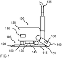
- Figure 1 shows a schematic side view of a vacuum cleaner 100 on a loading device 105 according to an embodiment. According to an alternative exemplary embodiment, this can also be a different household appliance instead of the vacuum cleaner 100.
- the charging device 105 is designed to charge an electrical energy storage unit 110 of the vacuum cleaner 100 when the vacuum cleaner 100 is arranged on the charging device 105 as shown.
- the loading device 105 has at least one erecting device 115 which is designed to erect the vacuum cleaner 100. Furthermore, the loading device 100 has an access ramp 120 which is shaped to allow the vacuum cleaner 100 to be placed on the Positioning device 115 open. According to this exemplary embodiment, the access ramp 120 is arranged circumferentially around an edge of the erecting device 115.
- the charging device 105 further comprises a charging unit 125, which is designed to contact the vacuum cleaner 100 in the erected state of the vacuum cleaner 100 on the installation device 115 in order to charge the energy storage unit 110. According to this exemplary embodiment, the loading unit 125 is arranged in a center of the positioning device 115.
- the vacuum cleaner 100 has a vacuum cleaner body 130 with the energy storage unit 110, a vacuum cleaner hose 135, a floor nozzle 140, a contact unit 145 and a plurality of rollers 150.
- the contact unit 145 of the vacuum cleaner 100 makes contact with the charging unit 125 of the charging device 105, as a result of which the electrical energy storage unit 110 of the vacuum cleaner is charged.
- the contact unit 145 can be arranged on the vacuum cleaner 100 such that it can be sprung.
- the loading device 105 optionally has a further loading unit 155 in the area of an edge of the loading device 105, here on a section of the access ramp 120.
- the further charging unit 155 is designed to charge a floor nozzle energy storage unit 160 of the floor nozzle 140 upon contact with the floor nozzle 140.
- the charging device 105 presented can also be referred to as a charging island, charging station or charging plate for a battery-powered canister vacuum cleaner.
- the charging device 105 has the advantage that a charging plug does not have to be handled before and after each charging process. Furthermore, it is not necessary to lift and switch off the entire device, that is to say the vacuum cleaner 100, before and after each charging process.
- the joining of the vacuum cleaner 100 to the charging device 105 can take place in a defined position, the coaxially arranged charging contacts allowing a large number of positions with respect to the rotation of the vacuum cleaner 100 on the charging plate 105.
- the handling of the vacuum cleaner 100 and the charging device 100 is simplified. It is not necessary to lift the vacuum cleaner 100, since the vacuum cleaner 100 can be pulled up onto the loading device 105 and pulled down from the loading device 105 from any angle.
- the floor nozzle 140 is charged when the vacuum cleaner 100 is placed on the charging device 105 through contact between the floor nozzle 140 and the charging device 105; the vacuum cleaner 100 is charged when the vacuum cleaner 100 comes into contact with the charging device 105.
- FIG 2 shows a cross section of a charging device 105 according to an embodiment. This can be based on Figure 1 act described loading device 105.
- the loading unit 125 is coupled to the positioning device 115 such that it can be sprung.
- the loading device 105 has a resilient foam 200 between the loading unit 125 and the erection device 115.
- the charging device 105 can also have another resilient medium instead of the foam 200.
- Fig. 3 shows a cross section of a charging device 105 according to an embodiment. This can be one of the charging devices 105 described with reference to the preceding figures.
- the positioning device 115 has a recess 300 which is shaped to at least partially receive at least one of the rollers of the vacuum cleaner on the positioning device 115 when the vacuum cleaner is in the upright state.
- the recess 300 is shaped to run circularly around the loading unit 125.
- a surface 305 of the positioning device 115 is designed to be rotatable.
- the loading device 105 When the vacuum cleaner is arranged on the loading device 105, the loading device 105 and the vacuum cleaner can be rotated relative to one another.
- the loading device 105 has the shape of a circular plate.
- In the middle of the charging device 105 is a coaxial charging contact in the form of the charging unit 125.
- the vacuum cleaner can be pulled into the circular fairway in the form of the recess 300 of the charging device 105 from any angle.
- Fig. 4 shows a perspective top view of a charging device 105 according to an embodiment. This can be one of the charging devices 105 described with reference to the preceding figures.
- the positioning device 115 is round.
- the plate-shaped loading device 105 which can also be referred to as a freestyle loading plate, has the circumferential access ramp 120 so that the vacuum cleaner can be pulled onto and off the loading device 100 from any angle.
- the circumferential flat recess 300 serves as a channel for the rollers of the vacuum cleaner.
- the vacuum cleaner can be rotated in the fairway.
- a compression of the coaxial loading unit 125 when moving the vacuum cleaner up and down is realized by inclined planes.
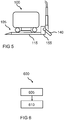
- Fig. 5 shows a schematic side view of a vacuum cleaner 100 on a loading device 105 according to an embodiment. This can be one of the charging devices 105 described with reference to the preceding figures with the in Fig. 1 Act described vacuum cleaner 100.
- the further charging unit 155 is designed to partially accommodate the floor nozzle 140, which can also be referred to as a battery electric nozzle.
- the floor nozzle 140 is suspended in a parking position in the further charging unit 155.
- FIG. 6 shows a flow chart of a method 600 for charging a household appliance with an electrical energy storage unit according to an exemplary embodiment. This can be a method 600 that can be carried out by one of the charging devices described with reference to the preceding figures.
- the household appliance can use the Figures 1 or 5 featured vacuum cleaner.
- the charging device is provided.
- the household appliance is set up on the setting up device of the charging device in order to contact the household appliance with the charging unit in order to charge the energy storage unit of the household appliance.
Landscapes
- Engineering & Computer Science (AREA)
- Power Engineering (AREA)
- Robotics (AREA)
- Mechanical Engineering (AREA)
- Charge And Discharge Circuits For Batteries Or The Like (AREA)
- Electric Vacuum Cleaner (AREA)
Description
- Der hier vorgestellte Ansatz betrifft eine Ladevorrichtung zum Aufladen einer elektrischen Energiespeichereinheit für ein Haushaltgerät, ein Haushaltgerät mit einer elektrischen Energiespeichereinheit und zumindest einer Kontakteinheit und ein Verfahren zum Aufladen eines Haushaltgeräts mit einer elektrischen Energiespeichereinheit.
- Staubsauger mit einer Stromversorgung durch Akku-Technologie müssen regelmäßig geladen werden. Hierzu werden unterschiedliche Ladekonzepte angewandt. Es werden Geräte- oder Akku-Ladeschalen sowie externe oder interne Netzteile verwendet. Um den Ladevorgang zu starten, müssen deshalb in der Regel mehrere Handgriffe getätigt und ggf. schwer gehoben werden. Mögliche Vorgänge sind: Den Akku aus dem Gerät entnehmen, das Gerät in eine Ladestation heben, ein Netzteil an das Gerät anschließen, etc.
- Die
DE 198 57 685 A1 beschreibt einen Akkusauger mit Wandhalterung. - Die
WO 2016/ 114463 A1 offenbart einen Roboter, welcher über eine Ladestation aufladbar ist. Der Roboter kann die Ladestation dabei über eine Rampe autonom befahren und einen Ladevorgang seiner Energiespeichereinrichtung initiieren. Die Ladeeinheit der Ladestation ist dabei auf der für den Roboter befahrbaren Fläche angeordnet. - Die
US 2013 / 0335900 A1 offenbart einen Saugroboter, welcher über eine Ladestation aufladbar ist. Der Roboter kann die Ladestation dabei über eine Rampe autonom befahren und einen Ladevorgang seiner Energiespeichereinrichtung initiieren. Die Ladeeinheit der Ladestation ist dabei auf der für den Roboter befahrbaren Fläche angeordnet. - Die
WO 2015/082019 A1 offenbart ebenfalls einen Saugroboter, welcher über eine Ladestation aufladbar ist. Der Roboter kann die Ladestation dabei über eine Rampe autonom befahren und einen Ladevorgang seiner Energiespeichereinrichtung initiieren. Die Ladeeinheit der Ladestation ist dabei an einer Stirnfläche der Ladestation angeordnet. - Die
CA 2 951 060 A1 offenbart eine Ladestation für einen Roboter, wobei die Ladestation für den Roboter autonom befahrbar ist. - Die
US 9 376 027 B2 - Dem hier vorgestellten Ansatz liegt die Aufgabe zugrunde, eine verbesserte Ladevorrichtung zum Aufladen einer elektrischen Energiespeichereinheit für ein Haushaltgerät, ein verbessertes Haushaltgerät mit einer elektrischen Energiespeichereinheit und zumindest einer Kontakteinheit und ein verbessertes Verfahren zum Aufladen eines Haushaltgeräts mit einer elektrischen Energiespeichereinheit zu schaffen.
- Erfindungsgemäß wird diese Aufgabe durch den Akku Bodenstaubsauger gemäß Anspruch 1 gelöst. Vorteilhafte Ausgestaltungen und Weiterbildungen des Ansatzes ergeben sich aus den nachfolgenden Unteransprüchen.
- Die mit dem hier vorgestellten Ansatz erreichbaren Vorteile bestehen darin, dass ein Haushaltgerät wie ein möglicherweise schwerer und/oder unhandlicher Staubsauger zum Aufladen einer elektrischen Energiespeichereinheit des Staubsaugers nicht angehoben werden muss.
- Eine Ladevorrichtung zum Aufladen einer elektrischen Energiespeichereinheit für ein Haushaltgerät umfasst zumindest eine Aufstelleinrichtung zum Aufstellen des Haushaltgeräts. Weiterhin umfasst die Ladevorrichtung eine Auffahrrampe zum Auffahren des Haushaltgeräts auf die Aufstelleinrichtung. Letztendlich umfasst die Ladevorrichtung zumindest eine Ladeeinheit, die dazu ausgeformt ist, um das Haushaltgerät im aufgestellten Zustand des Haushaltgeräts auf der Aufstelleinrichtung zu kontaktieren, um die Energiespeichereinheit aufzuladen. Bei dem Haushaltgerät kann es sich beispielsweise um einen Staubsauger handeln. Durch die vorgestellte Ladevorrichtung ist vorteilhafterweise weder ein Entnehmen der Energiespeichereinheit aus dem Haushaltgerät noch ein Anheben des Haushaltgeräts zum Aufladen der Energiespeichereinheit nötig. Da das Haushaltgerät einfach über die Auffahrrampe auf die Aufstelleinrichtung gezogen werden kann, vereinfacht und verkürzt dies den Ladevorgang gegenüber bekannten Ladevorgängen.
- Unter einer Aufstelleinrichtung kann hierbei eine Einheit verstanden werden, auf die das Haushaltgerät gestellt (d. h. aufgestellt) wird.
- Um von allen Seiten gleichermaßen erreichbar zu sein, kann die Ladeeinheit im Bereich einer Mitte der Aufstelleinrichtung angeordnet sein. Wenn die Aufstelleinrichtung im Wesentlichen rund ausgeformt ist, kann ein Auffahren des Haushaltgeräts über die Auffahrrampe von allen Seiten aus besonders einfach vonstattengehen. Um das Haushaltgerät weiterhin von allen Seiten auf die Aufstelleinrichtung auffahrbar zu machen, ist es von Vorteil, wenn die Auffahrrampe umlaufend um einen Rand der Aufstelleinrichtung angeordnet ist.
- Gemäß einer Ausführungsform kann die Ladeeinheit federbar mit der Aufstelleinrichtung gekoppelt oder koppelbar sein, um die Ladeeinheit abhängig von einer Höhe eines auf der Aufstelleinrichtung angeordneten Haushaltgeräts zum Kontaktieren mit dem Haushaltgerät höhenverstellbar zu machen. So kann die Ladeeinheit beispielsweise zwischen dem Haushaltgerät und der Aufstelleinrichtung flexibel verstellbar oder anpassbar sein.
- Wenn die Aufstelleinrichtung zumindest eine Vertiefung aufweist, die dazu ausgeformt ist, um im aufgestellten Zustand des Haushaltgeräts auf der Aufstelleinrichtung zumindest eine Rolle des Haushaltgeräts zumindest teilweise aufzunehmen, kann eine Aufstellposition oder Aufstellstellung für das Haushaltgerät vorherbestimmbar sein. Die Vertiefung kann vorteilhafterweise kreisförmig um die Ladeeinheit herum verlaufend ausgeformt sein, um eine Fahrrinne für das Haushaltgerät auszuformen, die von allen Seiten nach dem Auffahren des Haushaltgeräts auf die Ladevorrichtung gleichermaßen erreichbar ist. Die Vertiefung kann jedoch auch nur teilweise kreisförmig um die Ladeeinheit herum verlaufend ausgeformt sein.
- Die Ladevorrichtung kann gemäß einer Ausführungsform im Bereich eines Rands der Ladevorrichtung zumindest eine weitere Ladeeinheit aufweisen, die dazu ausgebildet sein kann, um eine Bodendüse des Haushaltgeräts zu kontaktieren, um eine Bodendüsenenergiespeichereinheit der Bodendüse aufzuladen. Hierfür kann beispielsweise ein Abschnitt der Auffahrrampe dazu ausgebildet sein, um bei Kontakt mit der Bodendüse deren Bodendüsenenergiespeichereinheit aufzuladen. Die weitere Ladeeinheit kann aber auch dazu ausgeformt sein, um die Bodendüse zumindest teilweise aufzunehmen, um eine eigene Aufnahmeeinrichtung speziell für die Bodendüse zu schaffen, in der deren Bodendüsenenergiespeichereinheit aufgeladen werden kann.
- Eine Oberfläche der Aufstelleinrichtung kann zumindest teilweise drehbar ausgeformt sein, um das Haushaltgerät auf der Ladevorrichtung drehbar zu machen. Dies erleichtert eine Handhabung des Haushaltgeräts auf der Ladevorrichtung. So kann das Haushaltgerät beispielsweise auf die Ladevorrichtung gezogen werden, nach dem Laden beispielsweise um 180°gedreht werden, und dann entgegen der Aufziehrichtung einfach wieder von der Ladevorrichtung heruntergezogen werden.
- Ein Haushaltgerät weist eine elektrische Energiespeichereinheit und zumindest eine Kontakteinheit auf, die dazu ausgebildet ist, um in einem auf einer der vorgestellten Ladevorrichtungen aufgestellten Zustand des Haushaltgeräts die Ladeeinheit der Ladevorrichtung zu kontaktieren, um die elektrische Energiespeichereinheit des Haushaltgeräts aufzuladen. Ein hier vorgestelltes Haushaltgerät kann als Ersatz für bekannte Haushaltgeräte dienen, wobei die Energiespeichereinheit des vorgestellten Haushaltgeräts vorteilhafterweise einfach und ohne ein Anheben des Haushaltgeräts, lediglich durch ein Aufziehen des Haushaltgeräts auf die Ladevorrichtung, aufgeladen werden kann.
- Ausführungsbeispiele des Ansatzes sind in den Zeichnungen rein schematisch dargestellt und werden nachfolgend näher beschrieben. Es zeigt
- Figur 1
- eine schematische Seitenansicht eines Staubsaugers auf einer Ladevorrichtung gemäß einem Ausführungsbeispiel;
- Figur 2
- einen Querschnitt einer Ladevorrichtung gemäß einem Ausführungsbeispiel;
- Figur 3
- einen Querschnitt einer Ladevorrichtung gemäß einem Ausführungsbeispiel;
- Figur 4
- eine perspektivische Aufsicht auf eine Ladevorrichtung gemäß einem Ausführungsbeispiel;
- Figur 5
- eine schematische Seitenansicht eines Staubsaugers auf einer Ladevorrichtung gemäß einem Ausführungsbeispiel; und
- Figur 6
- ein Ablaufdiagramm eines Verfahrens zum Aufladen eines Staubsaugers mit einer elektrischen Energiespeichereinheit gemäß einem Ausführungsbeispiel.
-
Figur 1 zeigt eine schematische Seitenansicht eines Staubsaugers 100 auf einer Ladevorrichtung 105 gemäß einem Ausführungsbeispiel. Gemäß einem alternativen Ausführungsbeispiel kann es sich hierbei anstelle des Staubsaugers 100 auch um ein anderes Haushaltgerät handeln. - Die Ladevorrichtung 105 ist dazu ausgebildet, um eine elektrische Energiespeichereinheit 110 des Staubsaugers 100 aufzuladen, wenn der Staubsauger 100 wie dargestellt auf der Ladevorrichtung 105 angeordnet ist.
- Hierzu weist die Ladevorrichtung 105 zumindest eine Aufstelleinrichtung 115 auf, die dazu ausgeformt ist, um den Staubsauger 100 aufzustellen. Weiterhin weist die Ladevorrichtung 100 eine Auffahrrampe 120 auf, die dazu ausgeformt ist, um den Staubsauger 100 auf die Aufstelleinrichtung 115 aufzufahren. Gemäß diesem Ausführungsbeispiel ist die Auffahrrampe 120 umlaufend um einen Rand der Aufstelleinrichtung 115 angeordnet. Die Ladevorrichtung 105 umfasst weiterhin eine Ladeeinheit 125, die dazu ausgeformt ist, um den Staubsauger 100 im aufgestellten Zustand des Staubsaugers 100 auf der Aufstelleinrichtung 115 zu kontaktieren, um die Energiespeichereinheit 110 aufzuladen. Gemäß diesem Ausführungsbeispiel ist die Ladeeinheit 125 in einer Mitte der Aufstelleinrichtung 115 angeordnet.
- Der Staubsauger 100 weist gemäß diesem Ausführungsbeispiel einen Staubsaugerkörper 130 mit der Energiespeichereinheit 110, einen Staubsaugerschlauch 135, eine Bodendüse 140, eine Kontakteinheit 145 und eine Mehrzahl an Rollen 150 auf. Die Kontakteinheit 145 des Staubsaugers 100 kontaktiert gemäß diesem Ausführungsbeispiel die Ladeeinheit 125 der Ladevorrichtung 105, wodurch die elektrische Energiespeichereinheit 110 des Staubsaugers aufgeladen wird. Hierzu kann die Kontakteinheit 145 federbar an dem Staubsauger 100 angeordnet sein.
- Gemäß diesem Ausführungsbeispiel weist die Ladevorrichtung 105 optional im Bereich eines Rands der Ladevorrichtung 105, hier an einem Abschnitt der Auffahrrampe 120, eine weitere Ladeeinheit 155 auf. Die weitere Ladeeinheit 155 ist dazu ausgebildet, um bei Kontakt mit der Bodendüse 140 eine Bodendüsenenergiespeichereinheit 160 der Bodendüse 140 aufzuladen.
- Im Folgenden werden Ausführungsbeispiele anhand der
Figur 1 nochmals näher beschrieben:
Die vorgestellte Ladevorrichtung 105 kann auch als eine Lade-Insel, Ladestation oder ein Ladeteller für einen Akku-Bodenstaubsauger bezeichnet werden. Es ergibt sich durch die Ladevorrichtung 105 der Vorteil, dass ein Ladestecker vor- und nach jedem Ladevorgang nicht gehandhabt werden muss. Weiterhin ist es nicht nötig, das gesamte Gerät, also den Staubsauger 100, vor- und nach jedem Ladevorgang anzuheben und abzustellen. Das Fügen des Staubsaugers 100 mit der Ladevorrichtung 105 kann dabei in einer definierten Position erfolgen, wobei die koaxial angeordneten Ladekontakte eine Vielzahl von Positionen bezüglich der Drehung des Staubsaugers 100 auf dem Ladeteller 105 zulassen. Die Handhabung von Staubsauger 100 und Ladevorrichtung 100 wird vereinfacht. Das Anheben des Staubsaugers 100 ist nicht notwendig, da der Staubsauger 100 aus jedem beliebigen Winkel auf die Ladevorrichtung 105 herauf- und von der Ladevorrichtung 105 heruntergezogen werden kann. - Das Aufladen der Bodendüse 140 erfolgt beim Abstellen des Staubsaugers 100 auf die Ladevorrichtung 105 durch Kontakt zwischen der Bodendüse 140 und der Ladevorrichtung 105, das Aufladen des Staubsaugers 100 erfolgt durch Kontakt des Staubsaugers 100 mit der Ladevorrichtung 105.
-
Figur 2 zeigt einen Querschnitt einer Ladevorrichtung 105 gemäß einem Ausführungsbeispiel. Dabei kann es sich um die anhand vonFigur 1 beschriebene Ladevorrichtung 105 handeln. - Gemäß diesem Ausführungsbeispiel ist die Ladeeinheit 125 federbar mit der Aufstelleinrichtung 115 gekoppelt. Hierzu weist die Ladevorrichtung 105 zwischen der Ladeeinheit 125 und der Aufstelleinrichtung 115 einen federnden Schaum 200 auf. Gemäß einem alternativen Ausführungsbeispiel kann die Ladevorrichtung 105 anstelle des Schaums 200 auch ein anderes federndes Medium aufweisen.
-
Fig. 3 zeigt einen Querschnitt einer Ladevorrichtung 105 gemäß einem Ausführungsbeispiel. Dabei kann es sich um eine der anhand der vorangegangenen Figuren beschriebenen Ladevorrichtungen 105 handeln. - Gemäß diesem Ausführungsbeispiel weist die Aufstelleinrichtung 115 eine Vertiefung 300 auf, die dazu ausgeformt ist, um im aufgestellten Zustand des Staubsaugers auf der Aufstelleinrichtung 115 zumindest eine der Rollen des Staubsaugers zumindest teilweise aufzunehmen. Gemäß diesem Ausführungsbeispiel ist die Vertiefung 300 kreisförmig um die Ladeeinheit 125 herum verlaufend ausgeformt. Eine Oberfläche 305 der Aufstelleinrichtung 115 ist gemäß diesem Ausführungsbeispiel drehbar ausgeformt.
- Wenn der Staubsauger auf der Ladevorrichtung 105 angeordnet ist, können die Ladevorrichtung 105 und der Staubsauger zueinander verdreht werden. Die Ladevorrichtung 105 hat gemäß diesem Ausführungsbeispiel die Form eines kreisrunden Tellers. In der Mitte der Ladevorrichtung 105 befindet sich ein koaxialer Ladekontakt in Form der Ladeeinheit 125. Der Staubsauger kann aus jedem Winkel in die kreisrunde Fahrrinne in Form der Vertiefung 300 der Ladevorrichtung 105 gezogen werden.
-
Fig. 4 zeigt eine perspektivische Aufsicht auf eine Ladevorrichtung 105 gemäß einem Ausführungsbeispiel. Dabei kann es sich um eine der anhand der vorangegangenen Figuren beschriebenen Ladevorrichtungen 105 handeln. - Zu erkennen ist hier, dass die Aufstelleinrichtung 115 gemäß diesem Ausführungsbeispiel rund ausgeformt ist. Die Ladevorrichtung 105 in Tellerform, die auch als Freestyle-Ladeteller bezeichnet werden kann, weist die umlaufende Auffahrrampe 120 auf, sodass der Staubsauger aus jedem Winkel auf die und von der Ladevorrichtung 100 gezogen werden kann. Die umlaufende ebene Vertiefung 300 dient als Fahrrinne für die Rollen des Staubsaugers. Der Staubsauger kann gemäß diesem Ausführungsbeispiel in der Fahrrinne gedreht werden. Ein Einfedern der koaxialen Ladeeinheit 125 beim Herauf- und Herunterfahren des Staubsaugers wird durch schiefe Ebenen realisiert.
-
Fig. 5 zeigt eine schematische Seitenansicht eines Staubsaugers 100 auf einer Ladevorrichtung 105 gemäß einem Ausführungsbeispiel. Dabei kann es sich um eine der anhand der vorangegangenen Figuren beschriebenen Ladevorrichtungen 105 mit dem inFig. 1 beschriebenen Staubsauger 100 handeln. - Gemäß diesem Ausführungsbeispiel ist die weitere Ladeeinheit 155 dazu ausgebildet, um die Bodendüse 140, die auch als Akku-Elektrodüse bezeichnet werden kann, teilweise aufzunehmen. Zum Aufladen der Bodendüsenenergiespeichereinheit der Bodendüse 140 ist die Bodendüse 140 in einer Parking-Position in die weitere Ladeeinheit 155 eingehängt.
-
Fig. 6 zeigt ein Ablaufdiagramm eines Verfahrens 600 zum Aufladen eines Haushaltgeräts mit einer elektrischen Energiespeichereinheit gemäß einem Ausführungsbeispiel. Dabei kann es sich um ein Verfahren 600 handeln, das von einer der anhand der vorangegangenen Figuren beschriebenen Ladevorrichtungen ausführbar ist. Das Haushaltgerät kann der anhand derFiguren 1 oder5 vorgestellte Staubsauger sein. - In einem Schritt 605 des Bereitstellens wird die Ladevorrichtung bereitgestellt. In einem Schritt 610 des Aufstellens wird das Haushaltgerät auf die Aufstelleinrichtung der Ladevorrichtung aufgestellt zum Kontaktieren des Haushaltgeräts mit der Ladeeinheit, um die Energiespeichereinheit des Haushaltgeräts aufzuladen.
Claims (5)
- Akku-Bodenstaubsauger (100) mit einer Ladeeinrichtung (105) und mit einer elektrischen Energiespeichereinheit (110) und zumindest einer Kontakteinheit (145), die dazu ausgebildet ist, um in einem auf einer Ladevorrichtung (105) aufgestellten Zustand des Staubsaugers (100) eine Ladeeinheit (125) der Ladevorrichtung (105) zu kontaktieren, um die elektrische Energiespeichereinheit (110) des Staubsaugers (100) aufzuladen, wobei die Ladevorrichtung (105) zumindest die folgenden Merkmale aufweist: eine Aufstelleinrichtung (115) zum Aufstellen des Staubsaugers (100); eine Auffahrrampe (120) zum Auffahren des Staubsaugers (100) auf die Aufstelleinrichtung (115), wobei die Auffahrrampe (120) umlaufend um einen Rand der Aufstelleinrichtung angeordnet (115) ist; und zumindest eine Ladeeinheit (125) zum Aufladen der Energiespeichereinheit (110) des Staubsaugers (100), wobei die Ladeeinheit (125) dazu ausgeformt ist, um den Staubsauger (100) im aufgestellten Zustand des Staubsaugers (100) auf der Aufstelleinrichtung (115) zu kontaktieren, um die Energiespeichereinheit (110) aufzuladen; wobei die Ladeeinheit (125) im Bereich der Mitte der Aufstelleinrichtung (115) angeordnet ist, die Aufstelleinrichtung (115) zumindest eine Vertiefung (300) aufweist, die dazu ausgeformt ist, um im aufgestellten Zustand des Staubsaugers (100) auf der Aufstelleinrichtung (115) zumindest eine Rolle des Staubsaugers (100) zumindest teilweise aufzunehmen,
wobei
die Vertiefung (300) zumindest teilweise kreisförmig um die Ladeeinheit (125) herum verlaufend ausgeformt ist. - Akku-Bodenstaubsauger (100) mit einer Ladevorrichtung (105) gemäß Anspruch 1, bei der die Aufstelleinrichtung (115) im Wesentlichen rund ausgeformt ist.
- Akku-Bodenstaubsauger (100) mit einer Ladevorrichtung (105) gemäß einem der vorangegangenen Ansprüche, bei der die Ladeeinheit (125) federbar mit der Aufstelleinrichtung (115) gekoppelt oder koppelbar ist.
- Akku-Bodenstaubsauger (100) mit einer Ladevorrichtung (105) gemäß einem der vorangegangenen Ansprüche, bei der die Ladevorrichtung (105) im Bereich eines Rands der Ladevorrichtung (105) zumindest eine weitere Ladeeinheit (155) aufweist, die dazu ausgebildet ist, um eine Bodendüse (140) des Staubsaugers (100) zu kontaktieren, um eine Bodendüsenenergiespeichereinheit (160) der Bodendüse (140) aufzuladen.
- Akku-Bodenstaubsauger (100) mit einer Ladevorrichtung (105) gemäß einem der vorangegangenen Ansprüche, bei der eine Oberfläche (305) der Aufstelleinrichtung (115) zumindest teilweise drehbar ausgeformt ist.
Applications Claiming Priority (1)
| Application Number | Priority Date | Filing Date | Title |
|---|---|---|---|
| DE102016114338.3A DE102016114338A1 (de) | 2016-08-03 | 2016-08-03 | Ladevorrichtung für ein Haushaltgerät und Verfahren zum Aufladen eines Haushaltgeräts |
Publications (2)
| Publication Number | Publication Date |
|---|---|
| EP3280026A1 EP3280026A1 (de) | 2018-02-07 |
| EP3280026B1 true EP3280026B1 (de) | 2021-01-27 |
Family
ID=59285019
Family Applications (1)
| Application Number | Title | Priority Date | Filing Date |
|---|---|---|---|
| EP17178586.8A Active EP3280026B1 (de) | 2016-08-03 | 2017-06-29 | Akku-bodenstaubsauger mit ladevorrichtung |
Country Status (2)
| Country | Link |
|---|---|
| EP (1) | EP3280026B1 (de) |
| DE (1) | DE102016114338A1 (de) |
Families Citing this family (1)
| Publication number | Priority date | Publication date | Assignee | Title |
|---|---|---|---|---|
| DE102017125964A1 (de) * | 2017-11-07 | 2019-05-09 | Miele & Cie. Kg | Ladevorrichtung für Haushaltsgerät und Haushaltsgerät |
Family Cites Families (9)
| Publication number | Priority date | Publication date | Assignee | Title |
|---|---|---|---|---|
| DE19857685A1 (de) | 1998-12-14 | 2000-06-15 | Dabelstein Lutz | Stiel-Besen mit integrierter Akku-Staubsaugeinrichtung |
| EP1129657B1 (de) * | 2000-03-01 | 2008-07-16 | Matsushita Electric Industrial Co., Ltd. | Electrisches Reinigungsgerät |
| DE102010016263A1 (de) * | 2010-03-31 | 2011-10-06 | Vorwerk & Co. Interholding Gmbh | Basisstation für einen Saug- und/oder Kehrroboter |
| KR101192540B1 (ko) * | 2010-12-20 | 2012-10-17 | (주)마미로봇 | 무선 청소기용 다기능 충전기 |
| US9376027B2 (en) * | 2013-09-13 | 2016-06-28 | Deere & Company | Robotic mower inductive charging station |
| CN105848549B (zh) * | 2013-12-06 | 2018-03-06 | 阿尔弗雷德·凯驰两合公司 | 自行驶且自转向的地板清洁设备和清洁系统 |
| FR3021914B1 (fr) * | 2014-06-05 | 2018-02-23 | Aldebaran Robotics | Base de rechargement d'une batterie et procede de recharge mettant en oeuvre une telle base |
| CA2972252C (en) * | 2014-12-24 | 2023-02-28 | Irobot Corporation | Evacuation station |
| KR101607671B1 (ko) * | 2015-01-14 | 2016-03-31 | (주)바램시스템 | 구동 로봇 및 그 구동 로봇의 충전 스테이션 도킹 방법 |
-
2016
- 2016-08-03 DE DE102016114338.3A patent/DE102016114338A1/de not_active Ceased
-
2017
- 2017-06-29 EP EP17178586.8A patent/EP3280026B1/de active Active
Non-Patent Citations (1)
| Title |
|---|
| None * |
Also Published As
| Publication number | Publication date |
|---|---|
| EP3280026A1 (de) | 2018-02-07 |
| DE102016114338A1 (de) | 2018-02-08 |
Similar Documents
| Publication | Publication Date | Title |
|---|---|---|
| DE102018104762B4 (de) | Vorrichtung und Verfahren zum selbsttätigen Verbinden/Trennen eines Aufladeanschlusses mit einer Aufladeanschlussaufnahme eines Fahrzeugs | |
| EP2974640B2 (de) | Saugroboter mit rotierender borstwalze und reinigungsverfahren für eine borstwalze eines saugroboters | |
| CN202219866U (zh) | 一种全自动瓷砖包装设备的取箱装箱装置 | |
| WO2010094517A2 (de) | Autonome ladevorrichtung für plugin-hybrid-fahrzeuge | |
| WO2015104080A1 (de) | Elektrische ladevorrichtung, elektrische anschlussvorrichtung, system und verfahren zum laden einer batterie eines fahrzeugs | |
| CN203874866U (zh) | 自动捣药机构 | |
| EP2717109A1 (de) | Ladevorrichtung für ein selbstfahrendes Arbeitsgerät | |
| CN204895884U (zh) | 自动更换电池装置 | |
| CN109051718B (zh) | 一种工业生产用卸料机器人 | |
| CN205588968U (zh) | 电动汽车电池更换系统 | |
| WO2020058525A1 (de) | Ladevorrichtung zum laden eines elektrofahrzeugs | |
| DE102017009237A1 (de) | Ladevorrichtung zum autonomen Laden eines Transportmittels, sowie Verfahren zum Betreiben der Ladevorrichtung | |
| DE112011103747T5 (de) | Verschiebungsapparat und Verfahren zu dessen Bedienung | |
| CN109193265B (zh) | 一种电路对接装置及充电桩 | |
| DE102007036228A1 (de) | Verfahren und System zur Sicherstellung einer Verbindung zwischen einem mobilen Gerät und einem stationären Gerät, insbesondere zwischen einem akkumulatorbetriebenen Staubsammelroboter und einer Akkumulator-Ladestation | |
| CN103811724B (zh) | 一种铅酸蓄电池管式极板灌粉装置 | |
| EP3980293A1 (de) | Ladevorrichtung zum laden einer batterie eines kraftfahrzeugs | |
| EP3280026A1 (de) | Ladevorrichtung für ein haushaltgerät und verfahren zum aufladen eines haushaltgeräts | |
| CN203461357U (zh) | 车式防堵塞电弧炉供料装置 | |
| CN208236059U (zh) | 一种带可移动充电机器人的立体车库 | |
| CN209354877U (zh) | 一种停车场专用监控灵活的摄像头 | |
| CN208008042U (zh) | 一种高效转接定位装置 | |
| DE202009009688U1 (de) | Energieversorgungseinheit, Landfahrzeug und Austauschstation zum Austausch einer in einem Landfahrzeug enthaltenen Energieversorgungseinheit | |
| CN108001501A (zh) | 一种塑胶管件用搬运车 | |
| CN206589658U (zh) | 一种汽车电池仓总成 |
Legal Events
| Date | Code | Title | Description |
|---|---|---|---|
| PUAI | Public reference made under article 153(3) epc to a published international application that has entered the european phase |
Free format text: ORIGINAL CODE: 0009012 |
|
| STAA | Information on the status of an ep patent application or granted ep patent |
Free format text: STATUS: THE APPLICATION HAS BEEN PUBLISHED |
|
| STAA | Information on the status of an ep patent application or granted ep patent |
Free format text: STATUS: REQUEST FOR EXAMINATION WAS MADE |
|
| AK | Designated contracting states |
Kind code of ref document: A1 Designated state(s): AL AT BE BG CH CY CZ DE DK EE ES FI FR GB GR HR HU IE IS IT LI LT LU LV MC MK MT NL NO PL PT RO RS SE SI SK SM TR |
|
| AX | Request for extension of the european patent |
Extension state: BA ME |
|
| 17P | Request for examination filed |
Effective date: 20180117 |
|
| RBV | Designated contracting states (corrected) |
Designated state(s): AL AT BE BG CH CY CZ DE DK EE ES FI FR GB GR HR HU IE IS IT LI LT LU LV MC MK MT NL NO PL PT RO RS SE SI SK SM TR |
|
| STAA | Information on the status of an ep patent application or granted ep patent |
Free format text: STATUS: EXAMINATION IS IN PROGRESS |
|
| 17Q | First examination report despatched |
Effective date: 20190621 |
|
| RIC1 | Information provided on ipc code assigned before grant |
Ipc: A47L 9/28 20060101ALI20200819BHEP Ipc: H02J 7/00 20060101AFI20200819BHEP |
|
| GRAP | Despatch of communication of intention to grant a patent |
Free format text: ORIGINAL CODE: EPIDOSNIGR1 |
|
| STAA | Information on the status of an ep patent application or granted ep patent |
Free format text: STATUS: GRANT OF PATENT IS INTENDED |
|
| INTG | Intention to grant announced |
Effective date: 20201019 |
|
| GRAS | Grant fee paid |
Free format text: ORIGINAL CODE: EPIDOSNIGR3 |
|
| GRAA | (expected) grant |
Free format text: ORIGINAL CODE: 0009210 |
|
| STAA | Information on the status of an ep patent application or granted ep patent |
Free format text: STATUS: THE PATENT HAS BEEN GRANTED |
|
| AK | Designated contracting states |
Kind code of ref document: B1 Designated state(s): AL AT BE BG CH CY CZ DE DK EE ES FI FR GB GR HR HU IE IS IT LI LT LU LV MC MK MT NL NO PL PT RO RS SE SI SK SM TR |
|
| REG | Reference to a national code |
Ref country code: GB Ref legal event code: FG4D Free format text: NOT ENGLISH |
|
| REG | Reference to a national code |
Ref country code: CH Ref legal event code: EP |
|
| REG | Reference to a national code |
Ref country code: DE Ref legal event code: R084 Ref document number: 502017009202 Country of ref document: DE |
|
| REG | Reference to a national code |
Ref country code: AT Ref legal event code: REF Ref document number: 1359208 Country of ref document: AT Kind code of ref document: T Effective date: 20210215 |
|
| REG | Reference to a national code |
Ref country code: IE Ref legal event code: FG4D Free format text: LANGUAGE OF EP DOCUMENT: GERMAN |
|
| REG | Reference to a national code |
Ref country code: DE Ref legal event code: R096 Ref document number: 502017009202 Country of ref document: DE |
|
| REG | Reference to a national code |
Ref country code: GB Ref legal event code: 746 Effective date: 20210420 |
|
| REG | Reference to a national code |
Ref country code: NL Ref legal event code: MP Effective date: 20210127 |
|
| REG | Reference to a national code |
Ref country code: LT Ref legal event code: MG9D |
|
| PG25 | Lapsed in a contracting state [announced via postgrant information from national office to epo] |
Ref country code: BG Free format text: LAPSE BECAUSE OF FAILURE TO SUBMIT A TRANSLATION OF THE DESCRIPTION OR TO PAY THE FEE WITHIN THE PRESCRIBED TIME-LIMIT Effective date: 20210427 Ref country code: LT Free format text: LAPSE BECAUSE OF FAILURE TO SUBMIT A TRANSLATION OF THE DESCRIPTION OR TO PAY THE FEE WITHIN THE PRESCRIBED TIME-LIMIT Effective date: 20210127 Ref country code: GR Free format text: LAPSE BECAUSE OF FAILURE TO SUBMIT A TRANSLATION OF THE DESCRIPTION OR TO PAY THE FEE WITHIN THE PRESCRIBED TIME-LIMIT Effective date: 20210428 Ref country code: FI Free format text: LAPSE BECAUSE OF FAILURE TO SUBMIT A TRANSLATION OF THE DESCRIPTION OR TO PAY THE FEE WITHIN THE PRESCRIBED TIME-LIMIT Effective date: 20210127 Ref country code: HR Free format text: LAPSE BECAUSE OF FAILURE TO SUBMIT A TRANSLATION OF THE DESCRIPTION OR TO PAY THE FEE WITHIN THE PRESCRIBED TIME-LIMIT Effective date: 20210127 Ref country code: PT Free format text: LAPSE BECAUSE OF FAILURE TO SUBMIT A TRANSLATION OF THE DESCRIPTION OR TO PAY THE FEE WITHIN THE PRESCRIBED TIME-LIMIT Effective date: 20210527 Ref country code: NO Free format text: LAPSE BECAUSE OF FAILURE TO SUBMIT A TRANSLATION OF THE DESCRIPTION OR TO PAY THE FEE WITHIN THE PRESCRIBED TIME-LIMIT Effective date: 20210427 |
|
| PG25 | Lapsed in a contracting state [announced via postgrant information from national office to epo] |
Ref country code: SE Free format text: LAPSE BECAUSE OF FAILURE TO SUBMIT A TRANSLATION OF THE DESCRIPTION OR TO PAY THE FEE WITHIN THE PRESCRIBED TIME-LIMIT Effective date: 20210127 Ref country code: RS Free format text: LAPSE BECAUSE OF FAILURE TO SUBMIT A TRANSLATION OF THE DESCRIPTION OR TO PAY THE FEE WITHIN THE PRESCRIBED TIME-LIMIT Effective date: 20210127 Ref country code: PL Free format text: LAPSE BECAUSE OF FAILURE TO SUBMIT A TRANSLATION OF THE DESCRIPTION OR TO PAY THE FEE WITHIN THE PRESCRIBED TIME-LIMIT Effective date: 20210127 Ref country code: LV Free format text: LAPSE BECAUSE OF FAILURE TO SUBMIT A TRANSLATION OF THE DESCRIPTION OR TO PAY THE FEE WITHIN THE PRESCRIBED TIME-LIMIT Effective date: 20210127 |
|
| PG25 | Lapsed in a contracting state [announced via postgrant information from national office to epo] |
Ref country code: IS Free format text: LAPSE BECAUSE OF FAILURE TO SUBMIT A TRANSLATION OF THE DESCRIPTION OR TO PAY THE FEE WITHIN THE PRESCRIBED TIME-LIMIT Effective date: 20210527 |
|
| REG | Reference to a national code |
Ref country code: DE Ref legal event code: R097 Ref document number: 502017009202 Country of ref document: DE |
|
| PG25 | Lapsed in a contracting state [announced via postgrant information from national office to epo] |
Ref country code: SM Free format text: LAPSE BECAUSE OF FAILURE TO SUBMIT A TRANSLATION OF THE DESCRIPTION OR TO PAY THE FEE WITHIN THE PRESCRIBED TIME-LIMIT Effective date: 20210127 Ref country code: CZ Free format text: LAPSE BECAUSE OF FAILURE TO SUBMIT A TRANSLATION OF THE DESCRIPTION OR TO PAY THE FEE WITHIN THE PRESCRIBED TIME-LIMIT Effective date: 20210127 Ref country code: EE Free format text: LAPSE BECAUSE OF FAILURE TO SUBMIT A TRANSLATION OF THE DESCRIPTION OR TO PAY THE FEE WITHIN THE PRESCRIBED TIME-LIMIT Effective date: 20210127 |
|
| PG25 | Lapsed in a contracting state [announced via postgrant information from national office to epo] |
Ref country code: SK Free format text: LAPSE BECAUSE OF FAILURE TO SUBMIT A TRANSLATION OF THE DESCRIPTION OR TO PAY THE FEE WITHIN THE PRESCRIBED TIME-LIMIT Effective date: 20210127 Ref country code: RO Free format text: LAPSE BECAUSE OF FAILURE TO SUBMIT A TRANSLATION OF THE DESCRIPTION OR TO PAY THE FEE WITHIN THE PRESCRIBED TIME-LIMIT Effective date: 20210127 Ref country code: DK Free format text: LAPSE BECAUSE OF FAILURE TO SUBMIT A TRANSLATION OF THE DESCRIPTION OR TO PAY THE FEE WITHIN THE PRESCRIBED TIME-LIMIT Effective date: 20210127 |
|
| PLBE | No opposition filed within time limit |
Free format text: ORIGINAL CODE: 0009261 |
|
| STAA | Information on the status of an ep patent application or granted ep patent |
Free format text: STATUS: NO OPPOSITION FILED WITHIN TIME LIMIT |
|
| 26N | No opposition filed |
Effective date: 20211028 |
|
| PG25 | Lapsed in a contracting state [announced via postgrant information from national office to epo] |
Ref country code: ES Free format text: LAPSE BECAUSE OF FAILURE TO SUBMIT A TRANSLATION OF THE DESCRIPTION OR TO PAY THE FEE WITHIN THE PRESCRIBED TIME-LIMIT Effective date: 20210127 Ref country code: AL Free format text: LAPSE BECAUSE OF FAILURE TO SUBMIT A TRANSLATION OF THE DESCRIPTION OR TO PAY THE FEE WITHIN THE PRESCRIBED TIME-LIMIT Effective date: 20210127 Ref country code: MC Free format text: LAPSE BECAUSE OF FAILURE TO SUBMIT A TRANSLATION OF THE DESCRIPTION OR TO PAY THE FEE WITHIN THE PRESCRIBED TIME-LIMIT Effective date: 20210127 |
|
| REG | Reference to a national code |
Ref country code: CH Ref legal event code: PL |
|
| PG25 | Lapsed in a contracting state [announced via postgrant information from national office to epo] |
Ref country code: SI Free format text: LAPSE BECAUSE OF FAILURE TO SUBMIT A TRANSLATION OF THE DESCRIPTION OR TO PAY THE FEE WITHIN THE PRESCRIBED TIME-LIMIT Effective date: 20210127 |
|
| REG | Reference to a national code |
Ref country code: BE Ref legal event code: MM Effective date: 20210630 |
|
| PG25 | Lapsed in a contracting state [announced via postgrant information from national office to epo] |
Ref country code: LU Free format text: LAPSE BECAUSE OF NON-PAYMENT OF DUE FEES Effective date: 20210629 |
|
| PG25 | Lapsed in a contracting state [announced via postgrant information from national office to epo] |
Ref country code: LI Free format text: LAPSE BECAUSE OF NON-PAYMENT OF DUE FEES Effective date: 20210630 Ref country code: IT Free format text: LAPSE BECAUSE OF FAILURE TO SUBMIT A TRANSLATION OF THE DESCRIPTION OR TO PAY THE FEE WITHIN THE PRESCRIBED TIME-LIMIT Effective date: 20210127 Ref country code: IE Free format text: LAPSE BECAUSE OF NON-PAYMENT OF DUE FEES Effective date: 20210629 Ref country code: CH Free format text: LAPSE BECAUSE OF NON-PAYMENT OF DUE FEES Effective date: 20210630 |
|
| PG25 | Lapsed in a contracting state [announced via postgrant information from national office to epo] |
Ref country code: IS Free format text: LAPSE BECAUSE OF FAILURE TO SUBMIT A TRANSLATION OF THE DESCRIPTION OR TO PAY THE FEE WITHIN THE PRESCRIBED TIME-LIMIT Effective date: 20210527 |
|
| PG25 | Lapsed in a contracting state [announced via postgrant information from national office to epo] |
Ref country code: BE Free format text: LAPSE BECAUSE OF NON-PAYMENT OF DUE FEES Effective date: 20210630 |
|
| PG25 | Lapsed in a contracting state [announced via postgrant information from national office to epo] |
Ref country code: HU Free format text: LAPSE BECAUSE OF FAILURE TO SUBMIT A TRANSLATION OF THE DESCRIPTION OR TO PAY THE FEE WITHIN THE PRESCRIBED TIME-LIMIT; INVALID AB INITIO Effective date: 20170629 |
|
| PG25 | Lapsed in a contracting state [announced via postgrant information from national office to epo] |
Ref country code: NL Free format text: LAPSE BECAUSE OF NON-PAYMENT OF DUE FEES Effective date: 20210127 Ref country code: CY Free format text: LAPSE BECAUSE OF FAILURE TO SUBMIT A TRANSLATION OF THE DESCRIPTION OR TO PAY THE FEE WITHIN THE PRESCRIBED TIME-LIMIT Effective date: 20210127 |
|
| P01 | Opt-out of the competence of the unified patent court (upc) registered |
Effective date: 20230528 |
|
| REG | Reference to a national code |
Ref country code: AT Ref legal event code: MM01 Ref document number: 1359208 Country of ref document: AT Kind code of ref document: T Effective date: 20220629 |
|
| PG25 | Lapsed in a contracting state [announced via postgrant information from national office to epo] |
Ref country code: AT Free format text: LAPSE BECAUSE OF NON-PAYMENT OF DUE FEES Effective date: 20220629 |
|
| PG25 | Lapsed in a contracting state [announced via postgrant information from national office to epo] |
Ref country code: MK Free format text: LAPSE BECAUSE OF FAILURE TO SUBMIT A TRANSLATION OF THE DESCRIPTION OR TO PAY THE FEE WITHIN THE PRESCRIBED TIME-LIMIT Effective date: 20210127 |
|
| PG25 | Lapsed in a contracting state [announced via postgrant information from national office to epo] |
Ref country code: TR Free format text: LAPSE BECAUSE OF FAILURE TO SUBMIT A TRANSLATION OF THE DESCRIPTION OR TO PAY THE FEE WITHIN THE PRESCRIBED TIME-LIMIT Effective date: 20210127 |
|
| PG25 | Lapsed in a contracting state [announced via postgrant information from national office to epo] |
Ref country code: MT Free format text: LAPSE BECAUSE OF FAILURE TO SUBMIT A TRANSLATION OF THE DESCRIPTION OR TO PAY THE FEE WITHIN THE PRESCRIBED TIME-LIMIT Effective date: 20210127 |
|
| PGFP | Annual fee paid to national office [announced via postgrant information from national office to epo] |
Ref country code: DE Payment date: 20250630 Year of fee payment: 9 |
|
| PGFP | Annual fee paid to national office [announced via postgrant information from national office to epo] |
Ref country code: GB Payment date: 20250617 Year of fee payment: 9 |
|
| PGFP | Annual fee paid to national office [announced via postgrant information from national office to epo] |
Ref country code: FR Payment date: 20250624 Year of fee payment: 9 |