EP3279994A1 - Lithium ion secondary battery and method of manufacturing same - Google Patents
Lithium ion secondary battery and method of manufacturing same Download PDFInfo
- Publication number
- EP3279994A1 EP3279994A1 EP16772939.1A EP16772939A EP3279994A1 EP 3279994 A1 EP3279994 A1 EP 3279994A1 EP 16772939 A EP16772939 A EP 16772939A EP 3279994 A1 EP3279994 A1 EP 3279994A1
- Authority
- EP
- European Patent Office
- Prior art keywords
- holes
- foil
- active material
- lithium
- current collector
- Prior art date
- Legal status (The legal status is an assumption and is not a legal conclusion. Google has not performed a legal analysis and makes no representation as to the accuracy of the status listed.)
- Withdrawn
Links
- HBBGRARXTFLTSG-UHFFFAOYSA-N Lithium ion Chemical compound [Li+] HBBGRARXTFLTSG-UHFFFAOYSA-N 0.000 title claims abstract description 73
- 229910001416 lithium ion Inorganic materials 0.000 title claims abstract description 73
- 238000004519 manufacturing process Methods 0.000 title claims abstract description 9
- 239000011888 foil Substances 0.000 claims abstract description 72
- 239000007773 negative electrode material Substances 0.000 claims abstract description 56
- 229910052782 aluminium Inorganic materials 0.000 claims abstract description 50
- XAGFODPZIPBFFR-UHFFFAOYSA-N aluminium Chemical compound [Al] XAGFODPZIPBFFR-UHFFFAOYSA-N 0.000 claims abstract description 50
- RYGMFSIKBFXOCR-UHFFFAOYSA-N Copper Chemical compound [Cu] RYGMFSIKBFXOCR-UHFFFAOYSA-N 0.000 claims abstract description 43
- 239000011889 copper foil Substances 0.000 claims abstract description 43
- NINIDFKCEFEMDL-UHFFFAOYSA-N Sulfur Chemical compound [S] NINIDFKCEFEMDL-UHFFFAOYSA-N 0.000 claims abstract description 33
- XUIMIQQOPSSXEZ-UHFFFAOYSA-N Silicon Chemical compound [Si] XUIMIQQOPSSXEZ-UHFFFAOYSA-N 0.000 claims abstract description 32
- 239000010703 silicon Substances 0.000 claims abstract description 32
- 229910052710 silicon Inorganic materials 0.000 claims abstract description 32
- 229910052717 sulfur Inorganic materials 0.000 claims abstract description 32
- 239000011593 sulfur Substances 0.000 claims abstract description 32
- ATJFFYVFTNAWJD-UHFFFAOYSA-N Tin Chemical compound [Sn] ATJFFYVFTNAWJD-UHFFFAOYSA-N 0.000 claims abstract description 31
- 239000007774 positive electrode material Substances 0.000 claims abstract description 29
- 229910052744 lithium Inorganic materials 0.000 claims description 16
- 239000005001 laminate film Substances 0.000 description 14
- 239000000047 product Substances 0.000 description 9
- 238000000034 method Methods 0.000 description 8
- 239000011255 nonaqueous electrolyte Substances 0.000 description 8
- 239000011230 binding agent Substances 0.000 description 7
- 239000000463 material Substances 0.000 description 7
- 239000000203 mixture Substances 0.000 description 7
- VZSRBBMJRBPUNF-UHFFFAOYSA-N 2-(2,3-dihydro-1H-inden-2-ylamino)-N-[3-oxo-3-(2,4,6,7-tetrahydrotriazolo[4,5-c]pyridin-5-yl)propyl]pyrimidine-5-carboxamide Chemical compound C1C(CC2=CC=CC=C12)NC1=NC=C(C=N1)C(=O)NCCC(N1CC2=C(CC1)NN=N2)=O VZSRBBMJRBPUNF-UHFFFAOYSA-N 0.000 description 6
- 230000000052 comparative effect Effects 0.000 description 6
- 239000002994 raw material Substances 0.000 description 6
- 239000011347 resin Substances 0.000 description 6
- 229920005989 resin Polymers 0.000 description 6
- OKTJSMMVPCPJKN-UHFFFAOYSA-N Carbon Chemical compound [C] OKTJSMMVPCPJKN-UHFFFAOYSA-N 0.000 description 5
- 239000012466 permeate Substances 0.000 description 5
- 239000003792 electrolyte Substances 0.000 description 4
- 238000011156 evaluation Methods 0.000 description 4
- 238000002156 mixing Methods 0.000 description 4
- LIVNPJMFVYWSIS-UHFFFAOYSA-N silicon monoxide Chemical compound [Si-]#[O+] LIVNPJMFVYWSIS-UHFFFAOYSA-N 0.000 description 4
- 239000000126 substance Substances 0.000 description 4
- WHXSMMKQMYFTQS-UHFFFAOYSA-N Lithium Chemical compound [Li] WHXSMMKQMYFTQS-UHFFFAOYSA-N 0.000 description 3
- 239000002033 PVDF binder Substances 0.000 description 3
- 239000004743 Polypropylene Substances 0.000 description 3
- 239000006230 acetylene black Substances 0.000 description 3
- 229910052751 metal Inorganic materials 0.000 description 3
- 239000002184 metal Substances 0.000 description 3
- -1 polypropylene Polymers 0.000 description 3
- 229920001155 polypropylene Polymers 0.000 description 3
- 229920002981 polyvinylidene fluoride Polymers 0.000 description 3
- 239000002002 slurry Substances 0.000 description 3
- XOLBLPGZBRYERU-UHFFFAOYSA-N tin dioxide Chemical compound O=[Sn]=O XOLBLPGZBRYERU-UHFFFAOYSA-N 0.000 description 3
- PXHVJJICTQNCMI-UHFFFAOYSA-N Nickel Chemical compound [Ni] PXHVJJICTQNCMI-UHFFFAOYSA-N 0.000 description 2
- 229910052799 carbon Inorganic materials 0.000 description 2
- 150000001875 compounds Chemical class 0.000 description 2
- 238000000866 electrolytic etching Methods 0.000 description 2
- 238000005530 etching Methods 0.000 description 2
- 238000010438 heat treatment Methods 0.000 description 2
- 150000002739 metals Chemical class 0.000 description 2
- 239000002904 solvent Substances 0.000 description 2
- HMUNWXXNJPVALC-UHFFFAOYSA-N 1-[4-[2-(2,3-dihydro-1H-inden-2-ylamino)pyrimidin-5-yl]piperazin-1-yl]-2-(2,4,6,7-tetrahydrotriazolo[4,5-c]pyridin-5-yl)ethanone Chemical compound C1C(CC2=CC=CC=C12)NC1=NC=C(C=N1)N1CCN(CC1)C(CN1CC2=C(CC1)NN=N2)=O HMUNWXXNJPVALC-UHFFFAOYSA-N 0.000 description 1
- WZFUQSJFWNHZHM-UHFFFAOYSA-N 2-[4-[2-(2,3-dihydro-1H-inden-2-ylamino)pyrimidin-5-yl]piperazin-1-yl]-1-(2,4,6,7-tetrahydrotriazolo[4,5-c]pyridin-5-yl)ethanone Chemical compound C1C(CC2=CC=CC=C12)NC1=NC=C(C=N1)N1CCN(CC1)CC(=O)N1CC2=C(CC1)NN=N2 WZFUQSJFWNHZHM-UHFFFAOYSA-N 0.000 description 1
- YLZOPXRUQYQQID-UHFFFAOYSA-N 3-(2,4,6,7-tetrahydrotriazolo[4,5-c]pyridin-5-yl)-1-[4-[2-[[3-(trifluoromethoxy)phenyl]methylamino]pyrimidin-5-yl]piperazin-1-yl]propan-1-one Chemical compound N1N=NC=2CN(CCC=21)CCC(=O)N1CCN(CC1)C=1C=NC(=NC=1)NCC1=CC(=CC=C1)OC(F)(F)F YLZOPXRUQYQQID-UHFFFAOYSA-N 0.000 description 1
- 241001474374 Blennius Species 0.000 description 1
- KMTRUDSVKNLOMY-UHFFFAOYSA-N Ethylene carbonate Chemical compound O=C1OCCO1 KMTRUDSVKNLOMY-UHFFFAOYSA-N 0.000 description 1
- NIPNSKYNPDTRPC-UHFFFAOYSA-N N-[2-oxo-2-(2,4,6,7-tetrahydrotriazolo[4,5-c]pyridin-5-yl)ethyl]-2-[[3-(trifluoromethoxy)phenyl]methylamino]pyrimidine-5-carboxamide Chemical compound O=C(CNC(=O)C=1C=NC(=NC=1)NCC1=CC(=CC=C1)OC(F)(F)F)N1CC2=C(CC1)NN=N2 NIPNSKYNPDTRPC-UHFFFAOYSA-N 0.000 description 1
- 239000004677 Nylon Substances 0.000 description 1
- 241000533293 Sesbania emerus Species 0.000 description 1
- FKNQFGJONOIPTF-UHFFFAOYSA-N Sodium cation Chemical compound [Na+] FKNQFGJONOIPTF-UHFFFAOYSA-N 0.000 description 1
- 238000004364 calculation method Methods 0.000 description 1
- 239000002800 charge carrier Substances 0.000 description 1
- 229910017052 cobalt Inorganic materials 0.000 description 1
- 239000010941 cobalt Substances 0.000 description 1
- GUTLYIVDDKVIGB-UHFFFAOYSA-N cobalt atom Chemical compound [Co] GUTLYIVDDKVIGB-UHFFFAOYSA-N 0.000 description 1
- IEJIGPNLZYLLBP-UHFFFAOYSA-N dimethyl carbonate Chemical compound COC(=O)OC IEJIGPNLZYLLBP-UHFFFAOYSA-N 0.000 description 1
- 238000002848 electrochemical method Methods 0.000 description 1
- JBTWLSYIZRCDFO-UHFFFAOYSA-N ethyl methyl carbonate Chemical compound CCOC(=O)OC JBTWLSYIZRCDFO-UHFFFAOYSA-N 0.000 description 1
- 238000002513 implantation Methods 0.000 description 1
- 229910000625 lithium cobalt oxide Inorganic materials 0.000 description 1
- BFZPBUKRYWOWDV-UHFFFAOYSA-N lithium;oxido(oxo)cobalt Chemical compound [Li+].[O-][Co]=O BFZPBUKRYWOWDV-UHFFFAOYSA-N 0.000 description 1
- 238000012423 maintenance Methods 0.000 description 1
- 238000005259 measurement Methods 0.000 description 1
- VNWKTOKETHGBQD-UHFFFAOYSA-N methane Chemical compound C VNWKTOKETHGBQD-UHFFFAOYSA-N 0.000 description 1
- 229910052759 nickel Inorganic materials 0.000 description 1
- 229920001778 nylon Polymers 0.000 description 1
- 238000007747 plating Methods 0.000 description 1
- 125000005575 polycyclic aromatic hydrocarbon group Chemical group 0.000 description 1
- 229920001195 polyisoprene Polymers 0.000 description 1
- 239000000843 powder Substances 0.000 description 1
- 238000002360 preparation method Methods 0.000 description 1
- 238000003825 pressing Methods 0.000 description 1
- 238000012545 processing Methods 0.000 description 1
- 229910001415 sodium ion Inorganic materials 0.000 description 1
- 229910001887 tin oxide Inorganic materials 0.000 description 1
- 235000012712 vegetable carbon Nutrition 0.000 description 1
- 239000004108 vegetable carbon Substances 0.000 description 1
- 238000003466 welding Methods 0.000 description 1
- 230000037303 wrinkles Effects 0.000 description 1
Images

Classifications
-
- H—ELECTRICITY
- H01—ELECTRIC ELEMENTS
- H01M—PROCESSES OR MEANS, e.g. BATTERIES, FOR THE DIRECT CONVERSION OF CHEMICAL ENERGY INTO ELECTRICAL ENERGY
- H01M4/00—Electrodes
- H01M4/02—Electrodes composed of, or comprising, active material
- H01M4/36—Selection of substances as active materials, active masses, active liquids
- H01M4/38—Selection of substances as active materials, active masses, active liquids of elements or alloys
- H01M4/386—Silicon or alloys based on silicon
-
- H—ELECTRICITY
- H01—ELECTRIC ELEMENTS
- H01M—PROCESSES OR MEANS, e.g. BATTERIES, FOR THE DIRECT CONVERSION OF CHEMICAL ENERGY INTO ELECTRICAL ENERGY
- H01M10/00—Secondary cells; Manufacture thereof
- H01M10/05—Accumulators with non-aqueous electrolyte
- H01M10/052—Li-accumulators
-
- H—ELECTRICITY
- H01—ELECTRIC ELEMENTS
- H01M—PROCESSES OR MEANS, e.g. BATTERIES, FOR THE DIRECT CONVERSION OF CHEMICAL ENERGY INTO ELECTRICAL ENERGY
- H01M10/00—Secondary cells; Manufacture thereof
- H01M10/05—Accumulators with non-aqueous electrolyte
- H01M10/052—Li-accumulators
- H01M10/0525—Rocking-chair batteries, i.e. batteries with lithium insertion or intercalation in both electrodes; Lithium-ion batteries
-
- H—ELECTRICITY
- H01—ELECTRIC ELEMENTS
- H01M—PROCESSES OR MEANS, e.g. BATTERIES, FOR THE DIRECT CONVERSION OF CHEMICAL ENERGY INTO ELECTRICAL ENERGY
- H01M10/00—Secondary cells; Manufacture thereof
- H01M10/05—Accumulators with non-aqueous electrolyte
- H01M10/058—Construction or manufacture
- H01M10/0585—Construction or manufacture of accumulators having only flat construction elements, i.e. flat positive electrodes, flat negative electrodes and flat separators
-
- H—ELECTRICITY
- H01—ELECTRIC ELEMENTS
- H01M—PROCESSES OR MEANS, e.g. BATTERIES, FOR THE DIRECT CONVERSION OF CHEMICAL ENERGY INTO ELECTRICAL ENERGY
- H01M4/00—Electrodes
- H01M4/02—Electrodes composed of, or comprising, active material
- H01M4/04—Processes of manufacture in general
- H01M4/0438—Processes of manufacture in general by electrochemical processing
- H01M4/0459—Electrochemical doping, intercalation, occlusion or alloying
- H01M4/0461—Electrochemical alloying
-
- H—ELECTRICITY
- H01—ELECTRIC ELEMENTS
- H01M—PROCESSES OR MEANS, e.g. BATTERIES, FOR THE DIRECT CONVERSION OF CHEMICAL ENERGY INTO ELECTRICAL ENERGY
- H01M4/00—Electrodes
- H01M4/02—Electrodes composed of, or comprising, active material
- H01M4/13—Electrodes for accumulators with non-aqueous electrolyte, e.g. for lithium-accumulators; Processes of manufacture thereof
-
- H—ELECTRICITY
- H01—ELECTRIC ELEMENTS
- H01M—PROCESSES OR MEANS, e.g. BATTERIES, FOR THE DIRECT CONVERSION OF CHEMICAL ENERGY INTO ELECTRICAL ENERGY
- H01M4/00—Electrodes
- H01M4/02—Electrodes composed of, or comprising, active material
- H01M4/13—Electrodes for accumulators with non-aqueous electrolyte, e.g. for lithium-accumulators; Processes of manufacture thereof
- H01M4/131—Electrodes based on mixed oxides or hydroxides, or on mixtures of oxides or hydroxides, e.g. LiCoOx
-
- H—ELECTRICITY
- H01—ELECTRIC ELEMENTS
- H01M—PROCESSES OR MEANS, e.g. BATTERIES, FOR THE DIRECT CONVERSION OF CHEMICAL ENERGY INTO ELECTRICAL ENERGY
- H01M4/00—Electrodes
- H01M4/02—Electrodes composed of, or comprising, active material
- H01M4/13—Electrodes for accumulators with non-aqueous electrolyte, e.g. for lithium-accumulators; Processes of manufacture thereof
- H01M4/136—Electrodes based on inorganic compounds other than oxides or hydroxides, e.g. sulfides, selenides, tellurides, halogenides or LiCoFy
-
- H—ELECTRICITY
- H01—ELECTRIC ELEMENTS
- H01M—PROCESSES OR MEANS, e.g. BATTERIES, FOR THE DIRECT CONVERSION OF CHEMICAL ENERGY INTO ELECTRICAL ENERGY
- H01M4/00—Electrodes
- H01M4/02—Electrodes composed of, or comprising, active material
- H01M4/36—Selection of substances as active materials, active masses, active liquids
- H01M4/38—Selection of substances as active materials, active masses, active liquids of elements or alloys
-
- H—ELECTRICITY
- H01—ELECTRIC ELEMENTS
- H01M—PROCESSES OR MEANS, e.g. BATTERIES, FOR THE DIRECT CONVERSION OF CHEMICAL ENERGY INTO ELECTRICAL ENERGY
- H01M4/00—Electrodes
- H01M4/02—Electrodes composed of, or comprising, active material
- H01M4/36—Selection of substances as active materials, active masses, active liquids
- H01M4/38—Selection of substances as active materials, active masses, active liquids of elements or alloys
- H01M4/387—Tin or alloys based on tin
-
- H—ELECTRICITY
- H01—ELECTRIC ELEMENTS
- H01M—PROCESSES OR MEANS, e.g. BATTERIES, FOR THE DIRECT CONVERSION OF CHEMICAL ENERGY INTO ELECTRICAL ENERGY
- H01M4/00—Electrodes
- H01M4/02—Electrodes composed of, or comprising, active material
- H01M4/36—Selection of substances as active materials, active masses, active liquids
- H01M4/48—Selection of substances as active materials, active masses, active liquids of inorganic oxides or hydroxides
- H01M4/483—Selection of substances as active materials, active masses, active liquids of inorganic oxides or hydroxides for non-aqueous cells
-
- H—ELECTRICITY
- H01—ELECTRIC ELEMENTS
- H01M—PROCESSES OR MEANS, e.g. BATTERIES, FOR THE DIRECT CONVERSION OF CHEMICAL ENERGY INTO ELECTRICAL ENERGY
- H01M4/00—Electrodes
- H01M4/02—Electrodes composed of, or comprising, active material
- H01M4/64—Carriers or collectors
- H01M4/66—Selection of materials
-
- H—ELECTRICITY
- H01—ELECTRIC ELEMENTS
- H01M—PROCESSES OR MEANS, e.g. BATTERIES, FOR THE DIRECT CONVERSION OF CHEMICAL ENERGY INTO ELECTRICAL ENERGY
- H01M4/00—Electrodes
- H01M4/02—Electrodes composed of, or comprising, active material
- H01M4/64—Carriers or collectors
- H01M4/66—Selection of materials
- H01M4/661—Metal or alloys, e.g. alloy coatings
-
- H—ELECTRICITY
- H01—ELECTRIC ELEMENTS
- H01M—PROCESSES OR MEANS, e.g. BATTERIES, FOR THE DIRECT CONVERSION OF CHEMICAL ENERGY INTO ELECTRICAL ENERGY
- H01M4/00—Electrodes
- H01M4/02—Electrodes composed of, or comprising, active material
- H01M4/64—Carriers or collectors
- H01M4/70—Carriers or collectors characterised by shape or form
-
- H—ELECTRICITY
- H01—ELECTRIC ELEMENTS
- H01M—PROCESSES OR MEANS, e.g. BATTERIES, FOR THE DIRECT CONVERSION OF CHEMICAL ENERGY INTO ELECTRICAL ENERGY
- H01M4/00—Electrodes
- H01M4/02—Electrodes composed of, or comprising, active material
- H01M4/64—Carriers or collectors
- H01M4/70—Carriers or collectors characterised by shape or form
- H01M4/72—Grids
- H01M4/74—Meshes or woven material; Expanded metal
- H01M4/742—Meshes or woven material; Expanded metal perforated material
-
- H—ELECTRICITY
- H01—ELECTRIC ELEMENTS
- H01M—PROCESSES OR MEANS, e.g. BATTERIES, FOR THE DIRECT CONVERSION OF CHEMICAL ENERGY INTO ELECTRICAL ENERGY
- H01M4/00—Electrodes
- H01M4/02—Electrodes composed of, or comprising, active material
- H01M2004/026—Electrodes composed of, or comprising, active material characterised by the polarity
- H01M2004/027—Negative electrodes
-
- H—ELECTRICITY
- H01—ELECTRIC ELEMENTS
- H01M—PROCESSES OR MEANS, e.g. BATTERIES, FOR THE DIRECT CONVERSION OF CHEMICAL ENERGY INTO ELECTRICAL ENERGY
- H01M4/00—Electrodes
- H01M4/02—Electrodes composed of, or comprising, active material
- H01M2004/026—Electrodes composed of, or comprising, active material characterised by the polarity
- H01M2004/028—Positive electrodes
-
- H—ELECTRICITY
- H01—ELECTRIC ELEMENTS
- H01M—PROCESSES OR MEANS, e.g. BATTERIES, FOR THE DIRECT CONVERSION OF CHEMICAL ENERGY INTO ELECTRICAL ENERGY
- H01M4/00—Electrodes
- H01M4/02—Electrodes composed of, or comprising, active material
- H01M4/13—Electrodes for accumulators with non-aqueous electrolyte, e.g. for lithium-accumulators; Processes of manufacture thereof
- H01M4/134—Electrodes based on metals, Si or alloys
-
- Y—GENERAL TAGGING OF NEW TECHNOLOGICAL DEVELOPMENTS; GENERAL TAGGING OF CROSS-SECTIONAL TECHNOLOGIES SPANNING OVER SEVERAL SECTIONS OF THE IPC; TECHNICAL SUBJECTS COVERED BY FORMER USPC CROSS-REFERENCE ART COLLECTIONS [XRACs] AND DIGESTS
- Y02—TECHNOLOGIES OR APPLICATIONS FOR MITIGATION OR ADAPTATION AGAINST CLIMATE CHANGE
- Y02E—REDUCTION OF GREENHOUSE GAS [GHG] EMISSIONS, RELATED TO ENERGY GENERATION, TRANSMISSION OR DISTRIBUTION
- Y02E60/00—Enabling technologies; Technologies with a potential or indirect contribution to GHG emissions mitigation
- Y02E60/10—Energy storage using batteries
-
- Y—GENERAL TAGGING OF NEW TECHNOLOGICAL DEVELOPMENTS; GENERAL TAGGING OF CROSS-SECTIONAL TECHNOLOGIES SPANNING OVER SEVERAL SECTIONS OF THE IPC; TECHNICAL SUBJECTS COVERED BY FORMER USPC CROSS-REFERENCE ART COLLECTIONS [XRACs] AND DIGESTS
- Y02—TECHNOLOGIES OR APPLICATIONS FOR MITIGATION OR ADAPTATION AGAINST CLIMATE CHANGE
- Y02P—CLIMATE CHANGE MITIGATION TECHNOLOGIES IN THE PRODUCTION OR PROCESSING OF GOODS
- Y02P70/00—Climate change mitigation technologies in the production process for final industrial or consumer products
- Y02P70/50—Manufacturing or production processes characterised by the final manufactured product
Definitions
- the present invention relates to a lithium-ion secondary battery that includes a positive electrode including a sulfur-based positive active material containing at least sulfur and a negative electrode including a silicon-based negative active material containing at least silicon or a tin-based negative active material containing tin, and to a method of manufacturing the lithium-ion secondary battery.
- the charge/discharge capacity of a lithium-ion secondary battery using sulfur alone as the positive active material is about six times or more the charge/discharge capacity of a lithium-ion secondary battery using a common lithium cobalt oxide positive electrode material, for example.
- a positive active material or a negative active material, a binder resin, and a conductive assistance are dispersed in a solvent to prepare slurry.
- the slurry is applied onto a plain metal foil that serves as a current collector, and the solvent in the slurry is dried and removed to form a mixture layer.
- the current collector and the mixture layer thereon are compacted using a roll pressing machine, and the binder resin is cured to fabricate a positive electrode and a negative electrode.
- Lithium is ionized and moved between the positive electrode and the negative electrode to serve as a substance (so-called charge carrier or carrier) involved in charge and discharge.
- lithium is contained in an electrolyte and the positive active material.
- the lithium-ion secondary battery according to the related art which includes a positive electrode including a sulfur-based positive active material containing at least sulfur and a negative electrode including a silicon-based negative active material containing at least silicon or a tin-based negative active material containing tin, none of the positive active material, the negative active material, and the electrolyte contains sufficient lithium ions. It is necessary to preliminarily dope lithium into the positive active material or the negative active material by an electrochemical method, and it is difficult to obtain a structure in which the positive electrode and the negative electrode are stacked via a separator.
- An object of the present invention is to provide a lithium-ion secondary battery, which includes a positive electrode including a sulfur-based positive active material containing at least sulfur and a negative electrode including a silicon-based negative active material containing at least silicon or a tin-based negative active material containing tin, and a method of manufacturing the same, which allows ready implantation and movement of lithium ions in a structure in which the positive electrode and the negative electrode are stacked via a separator.
- a lithium-ion secondary battery of the present invention includes a positive electrode, a negative electrode, and a separator.
- the positive electrode includes a positive current collector and a sulfur-based positive active material containing at least sulfur (S).
- the negative electrode includes a negative current collector and a silicon-based negative active material containing at least silicon (Si) or a tin-based negative active material containing tin (Sn).
- the positive current collector is made of an aluminum foil having a plurality of through holes.
- the negative current collector is made of a copper foil having a plurality of through holes.
- the positive electrode and the negative electrode are stacked via the separator.
- the aluminum foil having the plurality of through holes is used as the positive current collector and the copper foil having the plurality of through holes is used as the negative current collector, lithium ions are moved through the through holes formed in the current collectors even in a structure in which the positive electrode and the negative electrode are stacked via the separator. Therefore, the negative active material can be easily uniformly doped with the lithium ions.
- Either of a rolled copper foil and an electrolytic copper foil can be used as the copper foil. However, an electrolytic copper foil is preferably used.
- the aluminum foil is an aluminum perforated foil having a plurality of through holes formed to pierce the foil from a front surface to a back surface thereof.
- the aluminum perforated foil has a foil thickness of 50 ⁇ m or less, the through holes formed in the aluminum perforated foil have an average inside diameter of 2 to 500 ⁇ m, and the aluminum perforated foil has a hole opening rate of 3 to 50%.
- the copper foil having a plurality of through holes has a foil thickness of 50 ⁇ m or less, the through holes formed in the copper foil have an average inside diameter of 30 to 500 ⁇ m, and the copper foil has a hole opening rate of 3 to 50%.
- Use of such an aluminum perforated foil and a copper foil having a plurality of through holes allows the plurality of negative active materials to be doped with lithium ions, and is suitable for mass production of high-capacity lithium-ion secondary batteries.
- the average inside diameter of the through holes in the aluminum perforated foil is less than 2 ⁇ m, boring is difficult. If the average inside diameter is more than 500 ⁇ m, the positive active material mixture tends to fall off through the holes during application. If the hole opening rate of the through holes in the aluminum perforated foil is less than 3%, there is a possibility that the non-aqueous electrolyte does not sufficiently permeate into the positive active material. If the hole opening rate is more than 50%, the aluminum perforated foil tends to be wrinkled or torn during transport.
- the hole opening rate of the through holes in the aluminum perforated foil is more preferably 5 to 30% in order to reliably execute doping and prevent occurrence of a wrinkle or a tear.
- the average inside diameter of the through holes in the copper foil is less than 30 ⁇ m, boring is difficult. If the average inside diameter is more than 500 ⁇ m, the negative active material mixture tends to fall off through the holes during application.
- the average inside diameter of the through holes in the copper foil is more preferably 50 to 300 ⁇ m in order to facilitate forming of the through holes and prevent occurrence of fall-off through the holes. If the hole opening rate of the through holes in the copper foil is less than 3%, there is a possibility that the non-aqueous electrolyte does not sufficiently permeate into the negative active material. If the hole opening rate is more than 50%, the copper foil maybe wrinkled or torn during transport.
- the average inside diameter of the through holes in the aluminum perforated foil and the copper foil can be determined by various methods. Most conveniently, the average inside diameter can be obtained by magnifying the surface of the foil using a microscope, measuring the inside diameters of 100 through holes, and calculating the arithmetic mean of the measured values.
- the through holes are preferably shaped in a perfect circle or an ellipse or a polygon that is similar to a perfect circle for maintenance of the strength of the foil or ease of processing. If the through holes are in a shape other than a perfect circle, the average inside diameter of the through holes is calculated by additionally measuring the major axis and the minor axis.
- the hole opening rates of the aluminum perforated foil and the copper foil can be determined by the best method according to the method of forming the through holes etc. For example, if the through holes in the aluminum perforated foil are formed by electrolytic etching and a surface portion with no through holes is also etched, the hole opening rate calculated by the expression "measured weight of perforated foil/theoretical weight of non-perforated foil" is more or less inaccurate because of a reduction in measured weight due to the etched portion. Thus, a method of transmitting light through the perforated foil, binarizing the transmitted light, and calculating the hole opening rate from the white/black proportion is preferable.
- an accurate hole opening rate can be obtained using the expression "measured weight of perforated foil/theoretical weight of non-perforated foil” given above. It is to be noted, however, that calculation based on transmitted light can also be applied to obtain the hole opening rate.
- the through holes formed in the aluminum perforated foil and the through holes formed in the copper foil each have a density of 1 ⁇ 10 4 holes/m 2 or more.
- the density of the through holes per unit area can be obtained by measuring the distance between the centers of two adjacent through holes at the same time as the measurement of the average inside diameter described above, and calculating the density based on the distance between the centers, for example. If the through holes are irregularly arranged, the number of through holes per a segment having a certain area is to be measured.
- the respective hole opening rates of the aluminum perforated foil and the copper foil may be indicated by the following expression.
- hole opening rate % ⁇ R 2 4 ⁇ 10 ⁇ 12 ⁇ density holes / m 2 ⁇ 100
- a method of manufacturing a lithium-ion secondary battery of the present invention includes: preparing an electrode group by stacking a positive electrode and a negative electrode via a separator, the positive electrode including a positive current collector and a sulfur-based positive active material containing at least sulfur (S), and the negative electrode including a negative current collector and a silicon-based negative active material containing at least silicon (Si) or a tin-based negative active material containing tin (Sn), wherein the positive current collector is made of an aluminum foil having a plurality of through holes, and the negative current collector is made of a copper foil having a plurality of through holes; disposing a lithium metal sheet adjacent to the electrode group; electrically connecting the lithium metal sheet to the negative current collector to ionize the lithium metal sheet into lithium ions; and doping the silicon-based negative active material or the tin-based negative active material with the lithium ions.
- the negative active material can be easily doped uniformly with lithium ions even in a structure in which the
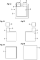
- Fig. 1A illustrates a schematic configuration of an example lithium-ion secondary battery 1 according to an embodiment of the present invention.
- Fig. 1B illustrates a positive electrode 3.
- Fig. 1C illustrates a negative electrode 7.
- Fig. 1D illustrates a separator 11.
- Fig. 1E illustrates a laminate film 12.
- Fig. 2 schematically illustrates the internal configuration of the embodiment.
- the positive electrode 3 includes a positive current collector 4 and a sulfur-based positive active material 5 containing at least sulfur (S).
- the negative electrode 7 includes a negative current collector 8 and a silicon-based negative active material 9 containing at least silicon (Si) or a tin-based negative active material 9 containing tin (Sn).
- Reference numerals 6 and 10 denote a positive electrode terminal lead and a negative electrode terminal lead, respectively.
- the positive current collector 4 is made of an aluminum foil having a plurality of through holes.
- the aluminum foil is an aluminum perforated foil having a plurality of through holes formed to pierce the foil from a front surface to a back surface thereof.
- the aluminum perforated foil has a foil thickness of 50 ⁇ m or less.
- the density of the through holes is 1 ⁇ 10 4 holes/m 2 or more.
- the average inside diameter of the through holes is 2 to 500 ⁇ m.
- the sulfur-based positive active material 5 is formed, for example, by mixing sulfur powder and carbon source compound powder with a binder to prepare a mixed paste raw material, applying the mixed paste raw material to the positive current collector, and thereafter heating (performing a heat treatment on) the positive current collector.
- the carbon source compound include pitch, polyisoprene, polycyclic aromatic hydrocarbons obtained by condensing three or more six-membered rings, and vegetable carbon materials such as coffee beans and seaweeds, etc.
- the negative current collector 8 is made of a copper foil having a plurality of through holes.
- the copper foil has a foil thickness of 50 ⁇ m or less.
- the density of the through holes is 1 ⁇ 10 4 holes/m 2 or more.
- the average inside diameter of the through holes is 30 to 500 ⁇ m.
- the negative active material layer contains a negative active material, a binder, and a conductive assistance, and is applied to both surfaces of the current collector.
- the negative active material contains silicon (Si) or tin (Sn).
- the positive electrode 3 and the negative electrode 7 are stacked via the separator 11.
- the separator 11 is a rectangular sheet made of a polypropylene resin.
- the laminate film 12 has a structure in which a resin and an aluminum foil are stacked.
- an electrode group 13 is sandwiched between a set of two laminate films 12, three sides of the laminate films 12 are sealed into a bag shape, and a predetermined non-aqueous electrolyte is poured into a space between the laminate films 12. After that, the remaining side of the laminate films 12 is sealed to form a laminate cell with the four sides tightly sealed and in which the electrode group 13 and the non-aqueous electrolyte are tightly enclosed.
- one or both of the copper foils 8A and 8B each having a plurality of through holes and the negative current collector 7 are electrically connected to each other.
- lithium ions are eluted from the lithium metal sheet 14, and pass through the plurality of through holes formed in the positive current collector 4 and the negative current collector 8 so that the silicon-based negative active material 9 or tin-based negative active material 9 is doped with the lithium ions.
- the lithium metal sheet 14 has been dissolved and does not exist any longer.
- the negative active material is doped with lithium ions through the through holes in the electrode foil. This significantly facilitates doping even in a structure in which the positive electrode and the negative electrode are stacked via the separator. Moreover, the negative active material can be uniformly doped with the lithium ions.
- Example lithium-ion secondary batteries according to the present invention will be described below.
- a lithium-ion secondary battery was manufactured using a positive active material containing sulfur (S) and a negative active material containing silicon (Si).
- An aluminum foil (thickness: 20 ⁇ m) for use in ordinary lithium-ion secondary batteries was subjected to a boring process by electrolytic etching to obtain a positive current collector having through holes formed thereon at a density of 1 ⁇ 10 9 holes/m 2 and with an average inside diameter of 10 ⁇ m.
- the hole opening rate was calculated by illuminating the foil with light from below, capturing an image of transmitted light and a non-transparent portion using a microscope, and binarizing the image. The hole opening rate was 22.5%.
- the positive current collector was heated to prepare a positive electrode.
- the positive active material mixture after being heated had 4.0 mg/cm 2 , and was shaped into 7 cm ⁇ 7.5 cm by shaving unnecessary portions.
- a copper foil (thickness: 15 ⁇ m) for use in ordinary lithium-ion secondary batteries was subjected to pattern printing and thereafter etching to form through holes to obtain a positive current collector with through holes having a density of 1 ⁇ 10 8 holes/m 2 and an average inside diameter of 50 ⁇ m.
- the measured weight of a square piece of 10 cm ⁇ 10 cm was 1.080 g, which was 19.8% (hole opening rate) of the theoretical weight (1.347 g).
- the negative current collector was heated to prepare a negative electrode.
- the negative active material mixture after being heated had 4.0 mg/cm 2 , and was shaped into 7 cm ⁇ 7.5 cm by shaving unnecessary portions.
- the separator was a rectangular sheet made of a polypropylene resin.
- the laminate film was formed mainly from nylon, aluminum, and a polypropylene resin.
- the separator and the laminate film were for use in ordinary lithium-ion secondary batteries.
- the positive electrode and the negative electrode were stacked via the separator in two layers for the positive electrode and in three layers for the negative electrode to form an electrode group.
- the laminate film of 20 cm ⁇ 11 cm was folded into half along the long side. Two sides of the laminate film were sealed into a bag shape. After that, the electrode group was inserted and a non-aqueous electrolyte was poured into the laminate film.
- the non-aqueous electrolyte included ethylene carbonate, dimethyl carbonate, and methylethyl carbonate, and was for use in ordinary lithium-ion secondary batteries. After that, the four sides of the laminate film were tightly sealed.
- the copper foils and the negative current collector were electrically connected to each other by ultrasonic welding.
- the cell was left to stand for two weeks at 50°C, which allowed lithium ions to be eluted from the lithium metal sheet and to be doped into the negative active material containing silicon.
- Lithium-ion secondary batteries according to Examples 1-2 to 1-7 were obtained under the same conditions as Example 1 except that the average inside diameter and the number of the through holes in the negative current collector were 2 ⁇ m and 1 ⁇ 10 11 holes/m 2 , 10 ⁇ m and 1 ⁇ 10 9 holes/m 2 , 50 ⁇ m and 1 ⁇ 10 8 holes/m 2 , 300 ⁇ m and 1 ⁇ 10 6 holes/m 2 , 500 ⁇ m and 5 ⁇ 10 8 holes/m 5 , and 700 ⁇ m and 2.5 ⁇ 10 6 holes/m 2 , respectively.
- a lithium-ion secondary battery according to Comparative Example 1-1 was obtained under the same conditions as Example 1-1 except that the negative current collector had no through holes.
- the discharge capacity was measured in an environment at 25°C. First, the battery was subjected to a constant current charge with a current value of 0.5 CA to an upper limit voltage of 2.2 V. When the upper limit voltage was reached, the battery was subjected to a constant voltage charge at 2.2 V for one hour. The battery was subjected to a constant current discharge with a current value of 0.5 CA to a lower limit voltage of 1V to calculate the capacity.
- a lithium-ion secondary battery was manufactured using a positive active material containing sulfur (S) and a negative active material containing silicon (Si).
- a lithium-ion secondary battery according to Example 2-1 was prepared under the same conditions as Example 1-1 except that an aluminum foil having through holes with an average inside diameter of 50 ⁇ m and with the number of the through holes being 1 ⁇ 10 8 holes/m 2 was used as the positive current collector and a copper foil having through holes with an average inside diameter of 10 ⁇ m and with the number of the through holes being 1 ⁇ 10 9 holes/m 2 was used as the negative current collector.
- Lithium-ion secondary batteries according to Examples 2-2 to 2-6 were obtained under the same conditions as Example 1 except that the average inside diameter and the number of the through holes in the positive current collector were 10 ⁇ m and 1 ⁇ 10 9 holes/m 2 , 50 ⁇ m and 1 ⁇ 10 8 holes/m 2 , 300 ⁇ m and 1 ⁇ 10 6 holes/m 2 , 500 ⁇ m and 5 ⁇ 10 8 holes/m 5 , and 700 ⁇ m and 2.5 ⁇ 10 6 holes/m 2 , respectively.
- Example 2-2 was the same as Example 1-3.
- a lithium-ion secondary battery according to Comparative Example 2-1 was obtained under the same conditions as Example 2-1 except that the positive current collector had no through holes.
- a lithium-ion secondary battery was manufactured using a positive active material containing sulfur (S) and a negative active material containing tin (Sn).
- the negative current collector was heated to prepare a negative electrode.
- the negative active material mixture after being heated had 4.0 mg/cm 2 , and was shaped into 7 cm ⁇ 7.5 cm by shaving unnecessary portions.
- the mixed paste raw material was applied to the negative current collector to prepare a negative electrode.
- Lithium-ion secondary batteries according to Examples 3-1 to 3-7, Comparative Example 3-1, Examples 4-1 to 4-6, and Comparative Example 4-1 were prepared through the same processes as Example 1, etc. described above except for preparation of the negative electrode.
- the discharge capacities of the lithium-ion secondary batteries were measured and evaluated. The results are indicated in Tables 3 and 4.
- lithium-ion secondary batteries having performance equivalent to that of the lithium-ion secondary batteries in which a silicon-based negative active material was used according to Example 1 etc. were obtained even if a tin-based negative active material containing tin (Sn) was used.
- an aluminum foil having a plurality of through holes is used as a positive current collector and a copper foil having a plurality of through holes is used as a negative current collector in a lithium-ion battery in which a positive electrode includes the positive current collector and a sulfur-based positive active material containing at least sulfur (S) and a negative electrode includes a negative current collector and a silicon-based negative active material containing at least silicon (Si) or a tin-based negative active material containing tin (Sn).
- Lithium ions are moved through the through holes formed in the current collectors. Therefore, the negative active material can be easily doped uniformly with the lithium ions, thereby facilitating manufacture of a lithium-ion battery in which a positive electrode and a negative electrode are stacked via a separator.
Landscapes
- Chemical & Material Sciences (AREA)
- Chemical Kinetics & Catalysis (AREA)
- Electrochemistry (AREA)
- General Chemical & Material Sciences (AREA)
- Engineering & Computer Science (AREA)
- Materials Engineering (AREA)
- Manufacturing & Machinery (AREA)
- Inorganic Chemistry (AREA)
- Cell Electrode Carriers And Collectors (AREA)
- Battery Electrode And Active Subsutance (AREA)
- Secondary Cells (AREA)
Abstract
Description
- The present invention relates to a lithium-ion secondary battery that includes a positive electrode including a sulfur-based positive active material containing at least sulfur and a negative electrode including a silicon-based negative active material containing at least silicon or a tin-based negative active material containing tin, and to a method of manufacturing the lithium-ion secondary battery.
- It is common that positive active materials for non-aqueous electrolyte secondary batteries such as lithium-ion secondary batteries and sodium-ion secondary batteries contain rare metals such as cobalt and nickel. However, such metals are available in small quantities and are expensive. In contrast, sulfur is currently available in a large quantity. Therefore, focus has been being placed on techniques in which sulfur (S) is used as a positive active material and silicon (Si) or tin (Sn) is used as a negative active material (see
JP 2005-251469 A JP 2013-191331 A - In the related art, a positive active material or a negative active material, a binder resin, and a conductive assistance are dispersed in a solvent to prepare slurry. The slurry is applied onto a plain metal foil that serves as a current collector, and the solvent in the slurry is dried and removed to form a mixture layer. The current collector and the mixture layer thereon are compacted using a roll pressing machine, and the binder resin is cured to fabricate a positive electrode and a negative electrode. Lithium is ionized and moved between the positive electrode and the negative electrode to serve as a substance (so-called charge carrier or carrier) involved in charge and discharge. In the related art, lithium is contained in an electrolyte and the positive active material.
-
- Patent Document 1:
JP 2005-251469 A - Patent Document 2:
JP 2013-191331 A - In the lithium-ion secondary battery according to the related art which includes a positive electrode including a sulfur-based positive active material containing at least sulfur and a negative electrode including a silicon-based negative active material containing at least silicon or a tin-based negative active material containing tin, none of the positive active material, the negative active material, and the electrolyte contains sufficient lithium ions. It is necessary to preliminarily dope lithium into the positive active material or the negative active material by an electrochemical method, and it is difficult to obtain a structure in which the positive electrode and the negative electrode are stacked via a separator.
- An object of the present invention is to provide a lithium-ion secondary battery, which includes a positive electrode including a sulfur-based positive active material containing at least sulfur and a negative electrode including a silicon-based negative active material containing at least silicon or a tin-based negative active material containing tin, and a method of manufacturing the same, which allows ready implantation and movement of lithium ions in a structure in which the positive electrode and the negative electrode are stacked via a separator.
- A lithium-ion secondary battery of the present invention includes a positive electrode, a negative electrode, and a separator. The positive electrode includes a positive current collector and a sulfur-based positive active material containing at least sulfur (S). The negative electrode includes a negative current collector and a silicon-based negative active material containing at least silicon (Si) or a tin-based negative active material containing tin (Sn). The positive current collector is made of an aluminum foil having a plurality of through holes. The negative current collector is made of a copper foil having a plurality of through holes. The positive electrode and the negative electrode are stacked via the separator. If the aluminum foil having the plurality of through holes is used as the positive current collector and the copper foil having the plurality of through holes is used as the negative current collector, lithium ions are moved through the through holes formed in the current collectors even in a structure in which the positive electrode and the negative electrode are stacked via the separator. Therefore, the negative active material can be easily uniformly doped with the lithium ions. Either of a rolled copper foil and an electrolytic copper foil can be used as the copper foil. However, an electrolytic copper foil is preferably used.
- Preferably, the aluminum foil is an aluminum perforated foil having a plurality of through holes formed to pierce the foil from a front surface to a back surface thereof. Preferably, the aluminum perforated foil has a foil thickness of 50 µm or less, the through holes formed in the aluminum perforated foil have an average inside diameter of 2 to 500 µm, and the aluminum perforated foil has a hole opening rate of 3 to 50%. Preferably, the copper foil having a plurality of through holes has a foil thickness of 50 µm or less, the through holes formed in the copper foil have an average inside diameter of 30 to 500 µm, and the copper foil has a hole opening rate of 3 to 50%. Use of such an aluminum perforated foil and a copper foil having a plurality of through holes allows the plurality of negative active materials to be doped with lithium ions, and is suitable for mass production of high-capacity lithium-ion secondary batteries.
- If the average inside diameter of the through holes in the aluminum perforated foil is less than 2 µm, boring is difficult. If the average inside diameter is more than 500 µm, the positive active material mixture tends to fall off through the holes during application. If the hole opening rate of the through holes in the aluminum perforated foil is less than 3%, there is a possibility that the non-aqueous electrolyte does not sufficiently permeate into the positive active material. If the hole opening rate is more than 50%, the aluminum perforated foil tends to be wrinkled or torn during transport. The hole opening rate of the through holes in the aluminum perforated foil is more preferably 5 to 30% in order to reliably execute doping and prevent occurrence of a wrinkle or a tear.
- If the average inside diameter of the through holes in the copper foil is less than 30 µm, boring is difficult. If the average inside diameter is more than 500 µm, the negative active material mixture tends to fall off through the holes during application. The average inside diameter of the through holes in the copper foil is more preferably 50 to 300 µm in order to facilitate forming of the through holes and prevent occurrence of fall-off through the holes. If the hole opening rate of the through holes in the copper foil is less than 3%, there is a possibility that the non-aqueous electrolyte does not sufficiently permeate into the negative active material. If the hole opening rate is more than 50%, the copper foil maybe wrinkled or torn during transport.
- The average inside diameter of the through holes in the aluminum perforated foil and the copper foil can be determined by various methods. Most conveniently, the average inside diameter can be obtained by magnifying the surface of the foil using a microscope, measuring the inside diameters of 100 through holes, and calculating the arithmetic mean of the measured values. The through holes are preferably shaped in a perfect circle or an ellipse or a polygon that is similar to a perfect circle for maintenance of the strength of the foil or ease of processing. If the through holes are in a shape other than a perfect circle, the average inside diameter of the through holes is calculated by additionally measuring the major axis and the minor axis.
- There are various methods to determine the hole opening rates of the aluminum perforated foil and the copper foil. The hole opening rates can be determined by the best method according to the method of forming the through holes etc. For example, if the through holes in the aluminum perforated foil are formed by electrolytic etching and a surface portion with no through holes is also etched, the hole opening rate calculated by the expression "measured weight of perforated foil/theoretical weight of non-perforated foil" is more or less inaccurate because of a reduction in measured weight due to the etched portion. Thus, a method of transmitting light through the perforated foil, binarizing the transmitted light, and calculating the hole opening rate from the white/black proportion is preferable. If the copper foil is formed by pattern plating or pattern printing and etching, an accurate hole opening rate can be obtained using the expression "measured weight of perforated foil/theoretical weight of non-perforated foil" given above. It is to be noted, however, that calculation based on transmitted light can also be applied to obtain the hole opening rate.
- In order to achieve uniform doping, preferably, the through holes formed in the aluminum perforated foil and the through holes formed in the copper foil each have a density of 1×10⁴ holes/m2 or more. The density of the through holes per unit area can be obtained by measuring the distance between the centers of two adjacent through holes at the same time as the measurement of the average inside diameter described above, and calculating the density based on the distance between the centers, for example. If the through holes are irregularly arranged, the number of through holes per a segment having a certain area is to be measured.
- When the density (holes/m2) of the through holes per unit area has been obtained, defining the respective average inside diameters of the through holes formed in the aluminum perforated foil and the through holes formed in the copper foil as R (µm), the respective hole opening rates of the aluminum perforated foil and the copper foil may be indicated by the following expression.

- A method of manufacturing a lithium-ion secondary battery of the present invention includes: preparing an electrode group by stacking a positive electrode and a negative electrode via a separator, the positive electrode including a positive current collector and a sulfur-based positive active material containing at least sulfur (S), and the negative electrode including a negative current collector and a silicon-based negative active material containing at least silicon (Si) or a tin-based negative active material containing tin (Sn), wherein the positive current collector is made of an aluminum foil having a plurality of through holes, and the negative current collector is made of a copper foil having a plurality of through holes; disposing a lithium metal sheet adjacent to the electrode group; electrically connecting the lithium metal sheet to the negative current collector to ionize the lithium metal sheet into lithium ions; and doping the silicon-based negative active material or the tin-based negative active material with the lithium ions. With the manufacturing method according to the present invention, the negative active material can be easily doped uniformly with lithium ions even in a structure in which the positive electrode and the negative electrode are stacked via the separator.
-
-
Fig. 1A illustrates a schematic configuration of an example lithium-ion secondary battery according to an embodiment of the present invention;Fig. 1B illustrates a positive electrode;Fig. 1C illustrates a negative electrode;Fig. 1D illustrates a separator; andFig. 1E illustrates a laminate film. -
Fig. 2 schematically illustrates the internal configuration of the embodiment. - An example lithium-ion secondary battery according to an embodiment of the present invention will be described below with reference to the drawings.
Fig. 1A illustrates a schematic configuration of an example lithium-ionsecondary battery 1 according to an embodiment of the present invention.Fig. 1B illustrates apositive electrode 3.Fig. 1C illustrates anegative electrode 7.Fig. 1D illustrates aseparator 11.Fig. 1E illustrates alaminate film 12.Fig. 2 schematically illustrates the internal configuration of the embodiment. - The
positive electrode 3 includes a positivecurrent collector 4 and a sulfur-based positiveactive material 5 containing at least sulfur (S). Thenegative electrode 7 includes a negativecurrent collector 8 and a silicon-based negativeactive material 9 containing at least silicon (Si) or a tin-based negativeactive material 9 containing tin (Sn).Reference numerals - The positive
current collector 4 is made of an aluminum foil having a plurality of through holes. The aluminum foil is an aluminum perforated foil having a plurality of through holes formed to pierce the foil from a front surface to a back surface thereof. The aluminum perforated foil has a foil thickness of 50 µm or less. The density of the through holes is 1×10⁴ holes/m2 or more. The average inside diameter of the through holes is 2 to 500 µm. - The sulfur-based positive
active material 5 is formed, for example, by mixing sulfur powder and carbon source compound powder with a binder to prepare a mixed paste raw material, applying the mixed paste raw material to the positive current collector, and thereafter heating (performing a heat treatment on) the positive current collector. Examples of the carbon source compound include pitch, polyisoprene, polycyclic aromatic hydrocarbons obtained by condensing three or more six-membered rings, and vegetable carbon materials such as coffee beans and seaweeds, etc. - The negative
current collector 8 is made of a copper foil having a plurality of through holes. The copper foil has a foil thickness of 50 µm or less. The density of the through holes is 1×10⁴ holes/m2 or more. The average inside diameter of the through holes is 30 to 500 µm. - The negative active material layer contains a negative active material, a binder, and a conductive assistance, and is applied to both surfaces of the current collector. The negative active material contains silicon (Si) or tin (Sn).
- The
positive electrode 3 and thenegative electrode 7 are stacked via theseparator 11. Theseparator 11 is a rectangular sheet made of a polypropylene resin. Thelaminate film 12 has a structure in which a resin and an aluminum foil are stacked. In the embodiment, anelectrode group 13 is sandwiched between a set of twolaminate films 12, three sides of thelaminate films 12 are sealed into a bag shape, and a predetermined non-aqueous electrolyte is poured into a space between thelaminate films 12. After that, the remaining side of thelaminate films 12 is sealed to form a laminate cell with the four sides tightly sealed and in which theelectrode group 13 and the non-aqueous electrolyte are tightly enclosed. - In the embodiment, in order to dope the negative active material with lithium ions, a stack of two copper foils 8A and 8B each having a plurality of through holes and a
lithium metal sheet 14 disposed therebetween, is disposed on one side of theelectrode group 13. During doping, one or both of the copper foils 8A and 8B each having a plurality of through holes and the negativecurrent collector 7 are electrically connected to each other. Through the electrical connection, lithium ions are eluted from thelithium metal sheet 14, and pass through the plurality of through holes formed in the positivecurrent collector 4 and the negativecurrent collector 8 so that the silicon-based negativeactive material 9 or tin-based negativeactive material 9 is doped with the lithium ions. When the lithium-ion secondary battery is completely charged, thelithium metal sheet 14 has been dissolved and does not exist any longer. - In the embodiment, the negative active material is doped with lithium ions through the through holes in the electrode foil. This significantly facilitates doping even in a structure in which the positive electrode and the negative electrode are stacked via the separator. Moreover, the negative active material can be uniformly doped with the lithium ions.
- Example lithium-ion secondary batteries according to the present invention will be described below.
- A lithium-ion secondary battery was manufactured using a positive active material containing sulfur (S) and a negative active material containing silicon (Si).
- An aluminum foil (thickness: 20 µm) for use in ordinary lithium-ion secondary batteries was subjected to a boring process by electrolytic etching to obtain a positive current collector having through holes formed thereon at a density of 1×10⁹ holes/m2 and with an average inside diameter of 10 µm. The hole opening rate was calculated by illuminating the foil with light from below, capturing an image of transmitted light and a non-transparent portion using a microscope, and binarizing the image. The hole opening rate was 22.5%.
- A mixed paste raw material prepared by mixing 4.8 g of sulfur (Wako Pure Chemical Industries, Ltd.; product number 195-04625; purity 98%) as a positive active material, 2.4 g of acetylene black (Denki Kagaku Kogyo; product number HS-100) as a conductive assistance, and 6.7 g of PVDF (Kureha Corporation; product number L#1120) as a binder was applied to both surfaces of the positive current collector. The positive current collector was heated to prepare a positive electrode. The positive active material mixture after being heated had 4.0 mg/cm2, and was shaped into 7 cm × 7.5 cm by shaving unnecessary portions.
- A copper foil (thickness: 15 µm) for use in ordinary lithium-ion secondary batteries was subjected to pattern printing and thereafter etching to form through holes to obtain a positive current collector with through holes having a density of 1×10⁸ holes/m2 and an average inside diameter of 50 µm. The measured weight of a square piece of 10 cm × 10 cm was 1.080 g, which was 19.8% (hole opening rate) of the theoretical weight (1.347 g).
- A mixed paste raw material prepared by mixing 6.4 g of silicon monoxide (SiO) (Wako Pure Chemical Industries, Ltd.; product number 198-05612; purity 99.9%) as a negative active material, 0.4 g of acetylene black (Denki Kagaku Kogyo; product number HS-100) as a conductive assistance, and 10 g of PVDF (Kureha Corporation; product number L#1120) as a binder was applied to both surfaces of the negative current collector. The negative current collector was heated to prepare a negative electrode. The negative active material mixture after being heated had 4.0 mg/cm2, and was shaped into 7 cm × 7.5 cm by shaving unnecessary portions.
- The separator was a rectangular sheet made of a polypropylene resin. The laminate film was formed mainly from nylon, aluminum, and a polypropylene resin. The separator and the laminate film were for use in ordinary lithium-ion secondary batteries. As illustrated in
Fig. 2 , the positive electrode and the negative electrode were stacked via the separator in two layers for the positive electrode and in three layers for the negative electrode to form an electrode group. The laminate film of 20 cm × 11 cm was folded into half along the long side. Two sides of the laminate film were sealed into a bag shape. After that, the electrode group was inserted and a non-aqueous electrolyte was poured into the laminate film. The non-aqueous electrolyte included ethylene carbonate, dimethyl carbonate, and methylethyl carbonate, and was for use in ordinary lithium-ion secondary batteries. After that, the four sides of the laminate film were tightly sealed. - In the cell, as illustrated in
Fig. 2 , a stack of two copper foils each having a plurality of through holes and a lithium metal sheet disposed therebetween, was disposed on one side of the electrode group. The copper foils and the negative current collector were electrically connected to each other by ultrasonic welding. The cell was left to stand for two weeks at 50°C, which allowed lithium ions to be eluted from the lithium metal sheet and to be doped into the negative active material containing silicon. - When the lithium metal sheet was dissolved, charge was completed, thereby obtaining a lithium-ion secondary battery according to Example 1-1.
- Lithium-ion secondary batteries according to Examples 1-2 to 1-7 were obtained under the same conditions as Example 1 except that the average inside diameter and the number of the through holes in the negative current collector were 2 µm and 1×10¹¹ holes/m2, 10 µm and 1×10⁹ holes/m2, 50 µm and 1×10⁸ holes/m2, 300 µm and 1×10⁶ holes/m2, 500 µm and 5×10⁸ holes/m5, and 700 µm and 2.5×10⁶ holes/m2, respectively.
- A lithium-ion secondary battery according to Comparative Example 1-1 was obtained under the same conditions as Example 1-1 except that the negative current collector had no through holes.
[Table 1] Average inside diameter (µm) of through holes Number (holes/m2) of holes Hole opening rate (%) Performance Capacity Evaluation Comp. Ex. 1-1 No through holes 0 0 39 mAh ×: Doping did not progress Ex. 1-1 1 1×10¹¹ 7.9 71 mAh Δ: Electrolyte did not sufficiently permeate Ex. 1-2 2 1×10¹¹ 31.4 195 mAh ○ Ex. 1-3 10 1×10⁹ 7.9 202 mAh ○ Ex. 1-4 50 1×10⁸ 19.6 212 mAh ○ Ex. 1-5 300 1×10⁶ 7.1 206 mAh ○ Ex. 1-6 500 5×10⁸ 9.8 197 mAh ○ Ex. 1-7 700 2.5×10⁶ 9.6 140 mAh Δ: Material fell off through holes in foil during application - The discharge capacity was measured in an environment at 25°C. First, the battery was subjected to a constant current charge with a current value of 0.5 CA to an upper limit voltage of 2.2 V. When the upper limit voltage was reached, the battery was subjected to a constant voltage charge at 2.2 V for one hour. The battery was subjected to a constant current discharge with a current value of 0.5 CA to a lower limit voltage of 1V to calculate the capacity.
- While doping did not progress when an aluminum foil with no through holes was used, doping progressed when an aluminum foil having through holes was used. The lithium-ion batteries, which used the aluminum foil having through holes with an average inside diameter of 2 µm to 500 µm, exhibited good performance. However, the non-aqueous electrolyte did not sufficiently permeate the through holes in the lithium-ion battery that used the aluminum foil having through holes with an average inside diameter of 1 µm, and the material fell off through the holes when applied to the positive current collector for the lithium-ion battery that used the aluminum foil having through holes with an average inside diameter of 700 µm. This result indicates lowered performance compared to lithium-ion batteries that used the aluminum foil having through holes with an average inside diameter of 2 µm to 500 µm.
- A lithium-ion secondary battery was manufactured using a positive active material containing sulfur (S) and a negative active material containing silicon (Si). A lithium-ion secondary battery according to Example 2-1 was prepared under the same conditions as Example 1-1 except that an aluminum foil having through holes with an average inside diameter of 50 µm and with the number of the through holes being 1×10⁸ holes/m2 was used as the positive current collector and a copper foil having through holes with an average inside diameter of 10 µm and with the number of the through holes being 1×10⁹ holes/m2 was used as the negative current collector.
- Lithium-ion secondary batteries according to Examples 2-2 to 2-6 were obtained under the same conditions as Example 1 except that the average inside diameter and the number of the through holes in the positive current collector were 10 µm and 1×10⁹ holes/m2, 50 µm and 1×10⁸ holes/m2, 300 µm and 1×10⁶ holes/m2, 500 µm and 5×10⁸ holes/m5, and 700 µm and 2.5×10⁶ holes/m2, respectively. Example 2-2 was the same as Example 1-3.
- A lithium-ion secondary battery according to Comparative Example 2-1 was obtained under the same conditions as Example 2-1 except that the positive current collector had no through holes.
[Table 2] Average inside diameter (µm) of through holes Number (holes/m2) of holes Hole opening rate (%) Performance Capacity Evaluation Comp. Ex. 2-1 No through holes 0 0 2 mAh ×: Doping did not progress Ex. 2-1 10 1×10⁹ 7.9 155 mAh Δ: Doping was not uniform Ex. 2-2 30 5×10⁸ 35.3 215 mAh ○ Ex. 2-3 50 1×10⁸ 19.6 210 mAh ○ Ex. 2-4 300 1×10⁶ 7.1 199 mAh ○ Ex. 2-5 500 5×10⁵ 9.8 204 mAh ○ Ex. 2-6 700 2.5×10⁵ 9.6 177 mAh Δ: Material fell off through holes in foil during application - While doping did not progress when a copper foil with no through holes was used, doping progressed when a copper foil having through holes was used. The lithium-ion batteries, which used the aluminum foil having through holes with an average inside diameter of 30 µm to 500 µm, exhibited good performance. However, doping was not uniform in the lithium-ion battery that used the aluminum foil having through holes with an average inside diameter of 10 µm, and the material fell off through the holes when applied to the positive current collector for the lithium-ion battery that used the aluminum foil having through holes with an average inside diameter of 700 µm. This result indicates lowered performance compared to lithium-ion batteries that used the aluminum foil having through holes with an average inside diameter of 30 µm to 500 µm.
- A lithium-ion secondary battery was manufactured using a positive active material containing sulfur (S) and a negative active material containing tin (Sn).
- A mixed paste raw material prepared by mixing 6.8 g of tin oxide (■) (SnO2) (Wako Pure Chemical Industries, Ltd.; product number 329-94293; purity 99.7%) as a negative active material, 0.5 g of acetylene black (Denki Kagaku Kogyo; product number HS-100) as a conductive assistance, and 5.8 g of PVDF (Kureha Corporation; product number L#1120) as a binder was applied to both surfaces of the negative current collector. The negative current collector was heated to prepare a negative electrode. The negative active material mixture after being heated had 4.0 mg/cm2, and was shaped into 7 cm × 7.5 cm by shaving unnecessary portions. The mixed paste raw material was applied to the negative current collector to prepare a negative electrode.
- Lithium-ion secondary batteries according to Examples 3-1 to 3-7, Comparative Example 3-1, Examples 4-1 to 4-6, and Comparative Example 4-1 were prepared through the same processes as Example 1, etc. described above except for preparation of the negative electrode. The discharge capacities of the lithium-ion secondary batteries were measured and evaluated. The results are indicated in Tables 3 and 4.
[Table 3] Average inside diameter (µm) of through holes Number (holes/m2) of holes Hole opening rate (%) Performance Capacity Evaluation Comp. Ex. 3-1 No through holes 0 0 30 mAh ×: Doping did not progress Ex. 3-1 1 1×10¹¹ 7.9 78 mAh Δ: Electrolyte did not sufficiently permeate Ex. 3-2 2 1×10¹¹ 31.4 208 mAh ○ Ex. 3-3 10 1×10⁹ 7.9 198 mAh ○ Ex. 3-4 50 1×10⁸ 19.6 195 mAh ○ Ex. 3-5 300 1×10⁶ 7.1 212 mAh ○ Ex. 3-6 500 5×10⁸ 9.8 203 mAh ○ Ex. 3-7 700 2.5×10⁶ 9.6 165 mAh Δ: Material fell off through holes in foil during application [Table 4] Average inside diameter (µm) of through holes Number (holes/m2) of holes Hole opening rate (%) Performance Capacity Evaluation Comp. Ex. 4-1 No through holes 0 0 3 mAh ×: Doping did not progress Ex. 4-1 10 1×10⁹ 7.9 172 mAh Δ: Doping was not uniform Ex. 4-2 30 5×10⁸ 35.3 208 mAh ○ Ex. 4-3 50 1×10⁸ 19.6 192 mAh ○ Ex. 4-4 300 1×10⁶ 7.1 197 mAh ○ Ex. 4-5 500 5×10⁵ 9.8 203 mAh ○ Ex. 4-6 700 2.5×10⁵ 9.6 156 mAh Δ: Material fell off through holes in foil during application - In this way, it was found that lithium-ion secondary batteries having performance equivalent to that of the lithium-ion secondary batteries in which a silicon-based negative active material was used according to Example 1 etc. were obtained even if a tin-based negative active material containing tin (Sn) was used.
- According to the present invention, an aluminum foil having a plurality of through holes is used as a positive current collector and a copper foil having a plurality of through holes is used as a negative current collector in a lithium-ion battery in which a positive electrode includes the positive current collector and a sulfur-based positive active material containing at least sulfur (S) and a negative electrode includes a negative current collector and a silicon-based negative active material containing at least silicon (Si) or a tin-based negative active material containing tin (Sn). Lithium ions are moved through the through holes formed in the current collectors. Therefore, the negative active material can be easily doped uniformly with the lithium ions, thereby facilitating manufacture of a lithium-ion battery in which a positive electrode and a negative electrode are stacked via a separator.
-
- 1 lithium-ion secondary battery
- 3 positive electrode
- 4 positive current collector
- 5 sulfur-based positive active material
- 6 positive electrode terminal lead
- 7 negative electrode
- 8 negative current collector
- 8A, 8B copper foil having a plurality of through holes
- 9 silicon-based negative active material or tin-based negative active material
- 10 negative electrode terminal lead
- 11 separator
- 12 laminate film
- 13 electrode group
- 14 lithium metal sheet
Claims (7)
- A lithium-ion secondary battery comprising:a positive electrode including a positive current collector and a sulfur-based positive active material containing at least sulfur (S);a negative electrode including a negative current collector and a silicon-based negative active material containing at least silicon (Si) or a tin-based negative active material containing tin (Sn); anda separator, wherein:the positive current collector is made of an aluminum foil having a plurality of through holes;the negative current collector is made of a copper foil having a plurality of through holes; andthe positive electrode and the negative electrode are stacked via the separator.
- The lithium-ion secondary battery according to claim 1, wherein:the aluminum foil is an aluminum perforated foil having a plurality of through holes formed to pierce the foil from a front surface to a back surface thereof;the aluminum perforated foil has a foil thickness of 50 µm or less;the through holes formed in the aluminum perforated foil have an average inside diameter of 2 to 500 µm;the aluminum perforated foil has a hole opening rate of 3 to 50%;the copper foil has a foil thickness of 50 µm or less;the through holes formed in the copper foil have an average inside diameter of 30 to 500 µm; andthe copper foil has a hole opening rate of 3 to 50%.
- The lithium-ion secondary battery according to claim 2, whereinthe aluminum perforated foil has a hole opening rate of 5 to 30%.
- The lithium-ion secondary battery according to claim 2 or 3, whereinthe through holes formed in the copper foil have an average inside diameter of 50 to 300 µm.
- The lithium-ion secondary battery according to any one of claims 1 to 4, whereinthe through holes formed in the aluminum perforated foil and the through holes formed in the copper foil each have a density of 1×10⁴ holes/m2 or more.
- The lithium-ion secondary battery according to any one of claims 2 to 5, whereinwhen the respective average inside diameters of the through holes formed in the aluminum perforated foil and the through holes formed in the copper foil are defined as R (µm), the respective hole opening rates of the aluminum perforated foil and the copper foil are indicated by the following expression:

- A method of manufacturing a lithium-ion secondary battery, comprising:preparing an electrode group by stacking a positive electrode and a negative electrode via a separator, the positive electrode including a positive current collector and a sulfur-based positive active material containing at least sulfur (S), and the negative electrode including a negative current collector and a silicon-based negative active material containing at least silicon (Si) or a tin-based negative active material containing tin (Sn), wherein the positive current collector is made of an aluminum foil having a plurality of through holes, and the negative current collector is made of a copper foil having a plurality of through holes;disposing a lithium metal sheet adjacent to the electrode group;electrically connecting the lithium metal sheet to the negative current collector to ionize the lithium metal sheet into lithium ions; anddoping the silicon-based negative active material or the tin-based negative active material with the lithium ions.
Applications Claiming Priority (2)
| Application Number | Priority Date | Filing Date | Title |
|---|---|---|---|
| JP2015069836 | 2015-03-30 | ||
| PCT/JP2016/060350 WO2016159058A1 (en) | 2015-03-30 | 2016-03-30 | Lithium ion secondary battery and method of manufacturing same |
Publications (2)
| Publication Number | Publication Date |
|---|---|
| EP3279994A1 true EP3279994A1 (en) | 2018-02-07 |
| EP3279994A4 EP3279994A4 (en) | 2018-09-26 |
Family
ID=57006063
Family Applications (1)
| Application Number | Title | Priority Date | Filing Date |
|---|---|---|---|
| EP16772939.1A Withdrawn EP3279994A4 (en) | 2015-03-30 | 2016-03-30 | Lithium ion secondary battery and method of manufacturing same |
Country Status (6)
| Country | Link |
|---|---|
| US (1) | US10340527B2 (en) |
| EP (1) | EP3279994A4 (en) |
| JP (1) | JPWO2016159058A1 (en) |
| KR (1) | KR20170131649A (en) |
| CN (1) | CN107431236A (en) |
| WO (1) | WO2016159058A1 (en) |
Cited By (1)
| Publication number | Priority date | Publication date | Assignee | Title |
|---|---|---|---|---|
| EP3483950A1 (en) * | 2017-11-10 | 2019-05-15 | Sumitomo Rubber Industries, Ltd. | Method of manufacturing lithium ion battery device and lithium ion battery device |
Families Citing this family (12)
| Publication number | Priority date | Publication date | Assignee | Title |
|---|---|---|---|---|
| CN106450489B (en) * | 2016-12-16 | 2019-09-20 | 天津力神电池股份有限公司 | An in-situ preparation method for lithium-sulfur batteries based on hard carbon negative electrodes |
| CN106450488B (en) * | 2016-12-16 | 2019-09-03 | 天津力神电池股份有限公司 | A kind of in-situ preparation method of lithium-sulfur battery based on silicon negative electrode |
| CN106785075B (en) * | 2016-12-16 | 2019-09-03 | 天津力神电池股份有限公司 | A kind of in-situ preparation method of lithium-sulfur battery based on graphite negative electrode |
| CN106450487B (en) * | 2016-12-16 | 2019-07-30 | 天津力神电池股份有限公司 | A kind of in-situ preparation method of lithium-sulfur cell structure |
| KR20190135053A (en) * | 2017-05-18 | 2019-12-05 | 후지필름 가부시키가이샤 | Perforated metal foil, method for manufacturing perforated metal foil, negative electrode for secondary battery and positive electrode for secondary battery |
| CN111033837A (en) * | 2017-08-23 | 2020-04-17 | 富士胶片株式会社 | Metal foil, method for producing metal foil, negative electrode for secondary battery, and positive electrode for secondary battery |
| KR20190076890A (en) | 2017-12-22 | 2019-07-02 | 주식회사 엘지화학 | Anode current for lithium metal battery and lithium metal battery including the same |
| CN111326717B (en) * | 2018-12-13 | 2021-11-16 | 深圳先进技术研究院 | Aluminum negative electrode material, preparation method and secondary battery |
| FR3091626B1 (en) * | 2019-01-08 | 2021-01-29 | Commissariat Energie Atomique | NEGATIVE ELECTRODES FOR USE IN ACCUMULATORS OPERATING ACCORDING TO THE PRINCIPLE OF IONIC INSERTION AND DISINSERTION OR OF ALLOY AND ACCUMULATOR FORMATION CONTAINING SUCH AN ELECTRODE |
| CN110247022B (en) * | 2019-06-24 | 2021-03-23 | 陈志勇 | SMT (surface mount technology) chip battery and pole piece and manufacturing method of SMT chip battery and pole piece |
| CN121484059A (en) * | 2023-04-27 | 2026-02-06 | 宁德时代新能源科技股份有限公司 | Positive electrode active materials, their preparation methods, positive electrode sheets, secondary batteries and electrical devices |
| WO2026004679A1 (en) * | 2024-06-25 | 2026-01-02 | 株式会社レゾナック | Electrode active material layer, nonaqueous secondary battery electrode, and nonaqueous secondary battery |
Family Cites Families (14)
| Publication number | Priority date | Publication date | Assignee | Title |
|---|---|---|---|---|
| JP2005251469A (en) | 2004-03-02 | 2005-09-15 | Sanyo Electric Co Ltd | Nonaqueous electrolyte battery |
| JP5301090B2 (en) * | 2006-08-18 | 2013-09-25 | 株式会社Kri | Electrode for lithium ion capacitor and lithium ion capacitor using the same |
| JP5171113B2 (en) * | 2007-05-30 | 2013-03-27 | 富士重工業株式会社 | Method for manufacturing power storage device |
| JP5220510B2 (en) | 2008-08-06 | 2013-06-26 | 富士重工業株式会社 | Electricity storage device |
| JP5235715B2 (en) * | 2009-02-25 | 2013-07-10 | 富士重工業株式会社 | Electric storage device and manufacturing method thereof |
| KR101758405B1 (en) * | 2009-10-23 | 2017-07-14 | 에스 이 아이 가부시키가이샤 | Methods for manufacturing lithium secondary battery and current-collecting foil for lithium secondary battery, and current-collecting foil for lithium secondary battery |
| KR101693916B1 (en) * | 2010-01-29 | 2017-01-09 | 제이에스알 가부시끼가이샤 | Electrochemical device |
| US8728663B2 (en) | 2010-04-16 | 2014-05-20 | Kabushiki Kaisha Toyota Jidoshokki | Positive electrode for lithium-ion secondary battery and lithium-ion secondary battery comprising that positive electrode |
| JP5668845B2 (en) * | 2011-05-23 | 2015-02-12 | 株式会社豊田自動織機 | ELECTRODE FOR LITHIUM ION SECONDARY BATTERY, MANUFACTURING METHOD THEREOF, AND LITHIUM ION SECONDARY BATTERY USING THE ELECTRODE |
| WO2012171450A1 (en) * | 2011-06-11 | 2012-12-20 | 苏州宝时得电动工具有限公司 | Electrode composite material, method thereof, positive electrode and battery including the same |
| JP5686076B2 (en) * | 2011-09-08 | 2015-03-18 | 株式会社豊田自動織機 | Method for producing lithium ion secondary battery |
| JP2013191331A (en) * | 2012-03-13 | 2013-09-26 | Toyota Industries Corp | Nonaqueous electrolyte secondary battery and vehicle |
| JP2013191328A (en) | 2012-03-13 | 2013-09-26 | Toyota Industries Corp | Nonaqueous electrolyte secondary battery and vehicle |
| CN104956521B (en) * | 2012-12-19 | 2018-06-29 | 亿目朗美国股份有限公司 | For the negative electrode active material of energy stores |
-
2016
- 2016-03-30 US US15/563,183 patent/US10340527B2/en not_active Expired - Fee Related
- 2016-03-30 JP JP2017510087A patent/JPWO2016159058A1/en active Pending
- 2016-03-30 CN CN201680018957.6A patent/CN107431236A/en active Pending
- 2016-03-30 KR KR1020177031109A patent/KR20170131649A/en not_active Withdrawn
- 2016-03-30 WO PCT/JP2016/060350 patent/WO2016159058A1/en not_active Ceased
- 2016-03-30 EP EP16772939.1A patent/EP3279994A4/en not_active Withdrawn
Cited By (2)
| Publication number | Priority date | Publication date | Assignee | Title |
|---|---|---|---|---|
| EP3483950A1 (en) * | 2017-11-10 | 2019-05-15 | Sumitomo Rubber Industries, Ltd. | Method of manufacturing lithium ion battery device and lithium ion battery device |
| US20190148778A1 (en) * | 2017-11-10 | 2019-05-16 | Sumitomo Rubber Industries, Ltd. | Method of manufacturing lithium ion battery device and lithium ion battery device |
Also Published As
| Publication number | Publication date |
|---|---|
| JPWO2016159058A1 (en) | 2018-02-01 |
| US20180083288A1 (en) | 2018-03-22 |
| KR20170131649A (en) | 2017-11-29 |
| CN107431236A (en) | 2017-12-01 |
| WO2016159058A1 (en) | 2016-10-06 |
| EP3279994A4 (en) | 2018-09-26 |
| US10340527B2 (en) | 2019-07-02 |
Similar Documents
| Publication | Publication Date | Title |
|---|---|---|
| US10340527B2 (en) | Lithium-ion secondary battery and method of manufacturing the same | |
| US10128547B2 (en) | Method for producing secondary battery | |
| US20170263933A1 (en) | Positive electrode for lithium-ion secondary cell, and lithium-ion secondary cell | |
| EP2461396A1 (en) | Method for producing battery electrode | |
| EP3193393A1 (en) | Positive electrode for lithium-ion secondary cell, and lithium-ion secondary cell | |
| KR20190065931A (en) | Copper foil for current collector of lithium secondary battery | |
| US20240204166A1 (en) | Secondary battery negative electrode, secondary battery, and method for manufacturing secondary battery negative electrode | |
| JP7136017B2 (en) | Non-aqueous electrolyte secondary battery | |
| JP7304380B2 (en) | Electrode current collector and secondary battery | |
| JP2005243455A (en) | Electrochemical device | |
| KR20250134055A (en) | Method for preparing the anode and secondary battery with enhanced high speed performance comprising the same | |
| EP4411870A1 (en) | Negative electrode for secondary batteries, and secondary battery | |
| JPWO2011048769A1 (en) | Flat secondary battery electrode group, method for manufacturing the same, and flat secondary battery electrode group provided with flat secondary battery electrode group | |
| JP3774980B2 (en) | Method for producing electrode for non-aqueous electrolyte secondary battery | |
| JP2011165930A (en) | Power storage device, and method of manufacturing shared negative electrode of the same | |
| JP2010278300A (en) | Method for manufacturing lithium ion capacitor | |
| EP4583191A1 (en) | Negative electrode for secondary batteries, secondary battery, and method for producing negative electrode for secondary batteries | |
| KR20200060287A (en) | Method for preparing the anode and secondary battery with enhanced high speed performance comprising the same | |
| EP3796453B1 (en) | Lithium ion secondary battery | |
| JP6628485B2 (en) | Method for producing lithium ion secondary battery and precursor of lithium ion secondary battery | |
| JP6729127B2 (en) | Lithium ion secondary battery | |
| EP4672358A1 (en) | Negative electrode for secondary batteries, secondary battery and method for producing a negative electrode for secondary batteries | |
| JP2003068284A (en) | Negative electrode for use in lithium secondary battery and is producing method, and lithium secondary battery | |
| JP2024534561A (en) | Prelithiation of Lithium-Ion Battery Anodes | |
| WO2024230897A1 (en) | Method for producing an electrode for an electrochemical storage cell |
Legal Events
| Date | Code | Title | Description |
|---|---|---|---|
| PUAI | Public reference made under article 153(3) epc to a published international application that has entered the european phase |
Free format text: ORIGINAL CODE: 0009012 |
|
| 17P | Request for examination filed |
Effective date: 20171024 |
|
| AK | Designated contracting states |
Kind code of ref document: A1 Designated state(s): AL AT BE BG CH CY CZ DE DK EE ES FI FR GB GR HR HU IE IS IT LI LT LU LV MC MK MT NL NO PL PT RO RS SE SI SK SM TR |
|
| AX | Request for extension of the european patent |
Extension state: BA ME |
|
| DAV | Request for validation of the european patent (deleted) | ||
| DAX | Request for extension of the european patent (deleted) | ||
| A4 | Supplementary search report drawn up and despatched |
Effective date: 20180824 |
|
| RIC1 | Information provided on ipc code assigned before grant |
Ipc: H01M 4/136 20100101ALI20180820BHEP Ipc: H01M 4/74 20060101ALN20180820BHEP Ipc: H01M 10/0525 20100101ALI20180820BHEP Ipc: H01M 10/0585 20100101ALI20180820BHEP Ipc: H01M 4/134 20100101ALI20180820BHEP Ipc: H01M 4/70 20060101ALI20180820BHEP Ipc: H01M 10/052 20100101AFI20180820BHEP Ipc: H01M 4/66 20060101ALI20180820BHEP |
|
| RIC1 | Information provided on ipc code assigned before grant |
Ipc: H01M 4/66 20060101ALI20190514BHEP Ipc: H01M 4/74 20060101ALN20190514BHEP Ipc: H01M 10/052 20100101AFI20190514BHEP Ipc: H01M 4/70 20060101ALI20190514BHEP Ipc: H01M 4/134 20100101ALI20190514BHEP Ipc: H01M 4/136 20100101ALI20190514BHEP Ipc: H01M 10/0525 20100101ALI20190514BHEP Ipc: H01M 10/0585 20100101ALI20190514BHEP |
|
| GRAP | Despatch of communication of intention to grant a patent |
Free format text: ORIGINAL CODE: EPIDOSNIGR1 |
|
| INTG | Intention to grant announced |
Effective date: 20190621 |
|
| STAA | Information on the status of an ep patent application or granted ep patent |
Free format text: STATUS: THE APPLICATION IS DEEMED TO BE WITHDRAWN |
|
| 18D | Application deemed to be withdrawn |
Effective date: 20191105 |