EP3279929A1 - Pressurization unit - Google Patents
Pressurization unit Download PDFInfo
- Publication number
- EP3279929A1 EP3279929A1 EP15880665.3A EP15880665A EP3279929A1 EP 3279929 A1 EP3279929 A1 EP 3279929A1 EP 15880665 A EP15880665 A EP 15880665A EP 3279929 A1 EP3279929 A1 EP 3279929A1
- Authority
- EP
- European Patent Office
- Prior art keywords
- pressure applying
- transferring
- pressure
- applying unit
- transferring member
- Prior art date
- Legal status (The legal status is an assumption and is not a legal conclusion. Google has not performed a legal analysis and makes no representation as to the accuracy of the status listed.)
- Withdrawn
Links
Images



Classifications
-
- B—PERFORMING OPERATIONS; TRANSPORTING
- B23—MACHINE TOOLS; METAL-WORKING NOT OTHERWISE PROVIDED FOR
- B23K—SOLDERING OR UNSOLDERING; WELDING; CLADDING OR PLATING BY SOLDERING OR WELDING; CUTTING BY APPLYING HEAT LOCALLY, e.g. FLAME CUTTING; WORKING BY LASER BEAM
- B23K20/00—Non-electric welding by applying impact or other pressure, with or without the application of heat, e.g. cladding or plating
- B23K20/02—Non-electric welding by applying impact or other pressure, with or without the application of heat, e.g. cladding or plating by means of a press ; Diffusion bonding
- B23K20/023—Thermo-compression bonding
-
- B—PERFORMING OPERATIONS; TRANSPORTING
- B23—MACHINE TOOLS; METAL-WORKING NOT OTHERWISE PROVIDED FOR
- B23K—SOLDERING OR UNSOLDERING; WELDING; CLADDING OR PLATING BY SOLDERING OR WELDING; CUTTING BY APPLYING HEAT LOCALLY, e.g. FLAME CUTTING; WORKING BY LASER BEAM
- B23K1/00—Soldering, e.g. brazing, or unsoldering
- B23K1/0008—Soldering, e.g. brazing, or unsoldering specially adapted for particular articles or work
- B23K1/0016—Soldering of electronic components
-
- B—PERFORMING OPERATIONS; TRANSPORTING
- B23—MACHINE TOOLS; METAL-WORKING NOT OTHERWISE PROVIDED FOR
- B23K—SOLDERING OR UNSOLDERING; WELDING; CLADDING OR PLATING BY SOLDERING OR WELDING; CUTTING BY APPLYING HEAT LOCALLY, e.g. FLAME CUTTING; WORKING BY LASER BEAM
- B23K20/00—Non-electric welding by applying impact or other pressure, with or without the application of heat, e.g. cladding or plating
- B23K20/002—Non-electric welding by applying impact or other pressure, with or without the application of heat, e.g. cladding or plating specially adapted for particular articles or work
-
- B—PERFORMING OPERATIONS; TRANSPORTING
- B23—MACHINE TOOLS; METAL-WORKING NOT OTHERWISE PROVIDED FOR
- B23K—SOLDERING OR UNSOLDERING; WELDING; CLADDING OR PLATING BY SOLDERING OR WELDING; CUTTING BY APPLYING HEAT LOCALLY, e.g. FLAME CUTTING; WORKING BY LASER BEAM
- B23K20/00—Non-electric welding by applying impact or other pressure, with or without the application of heat, e.g. cladding or plating
- B23K20/26—Auxiliary equipment
-
- H—ELECTRICITY
- H10—SEMICONDUCTOR DEVICES; ELECTRIC SOLID-STATE DEVICES NOT OTHERWISE PROVIDED FOR
- H10W—GENERIC PACKAGES, INTERCONNECTIONS, CONNECTORS OR OTHER CONSTRUCTIONAL DETAILS OF DEVICES COVERED BY CLASS H10
- H10W72/00—Interconnections or connectors in packages
- H10W72/071—Connecting or disconnecting
-
- B—PERFORMING OPERATIONS; TRANSPORTING
- B23—MACHINE TOOLS; METAL-WORKING NOT OTHERWISE PROVIDED FOR
- B23K—SOLDERING OR UNSOLDERING; WELDING; CLADDING OR PLATING BY SOLDERING OR WELDING; CUTTING BY APPLYING HEAT LOCALLY, e.g. FLAME CUTTING; WORKING BY LASER BEAM
- B23K2101/00—Articles made by soldering, welding or cutting
- B23K2101/36—Electric or electronic devices
- B23K2101/40—Semiconductor devices
-
- H—ELECTRICITY
- H10—SEMICONDUCTOR DEVICES; ELECTRIC SOLID-STATE DEVICES NOT OTHERWISE PROVIDED FOR
- H10W—GENERIC PACKAGES, INTERCONNECTIONS, CONNECTORS OR OTHER CONSTRUCTIONAL DETAILS OF DEVICES COVERED BY CLASS H10
- H10W72/00—Interconnections or connectors in packages
- H10W72/071—Connecting or disconnecting
- H10W72/0711—Apparatus therefor
- H10W72/07141—Means for applying energy, e.g. ovens or lasers
-
- H—ELECTRICITY
- H10—SEMICONDUCTOR DEVICES; ELECTRIC SOLID-STATE DEVICES NOT OTHERWISE PROVIDED FOR
- H10W—GENERIC PACKAGES, INTERCONNECTIONS, CONNECTORS OR OTHER CONSTRUCTIONAL DETAILS OF DEVICES COVERED BY CLASS H10
- H10W72/00—Interconnections or connectors in packages
- H10W72/071—Connecting or disconnecting
- H10W72/0711—Apparatus therefor
- H10W72/07178—Means for aligning
-
- H—ELECTRICITY
- H10—SEMICONDUCTOR DEVICES; ELECTRIC SOLID-STATE DEVICES NOT OTHERWISE PROVIDED FOR
- H10W—GENERIC PACKAGES, INTERCONNECTIONS, CONNECTORS OR OTHER CONSTRUCTIONAL DETAILS OF DEVICES COVERED BY CLASS H10
- H10W72/00—Interconnections or connectors in packages
- H10W72/071—Connecting or disconnecting
- H10W72/073—Connecting or disconnecting of die-attach connectors
-
- H—ELECTRICITY
- H10—SEMICONDUCTOR DEVICES; ELECTRIC SOLID-STATE DEVICES NOT OTHERWISE PROVIDED FOR
- H10W—GENERIC PACKAGES, INTERCONNECTIONS, CONNECTORS OR OTHER CONSTRUCTIONAL DETAILS OF DEVICES COVERED BY CLASS H10
- H10W72/00—Interconnections or connectors in packages
- H10W72/071—Connecting or disconnecting
- H10W72/073—Connecting or disconnecting of die-attach connectors
- H10W72/07331—Connecting techniques
-
- H—ELECTRICITY
- H10—SEMICONDUCTOR DEVICES; ELECTRIC SOLID-STATE DEVICES NOT OTHERWISE PROVIDED FOR
- H10W—GENERIC PACKAGES, INTERCONNECTIONS, CONNECTORS OR OTHER CONSTRUCTIONAL DETAILS OF DEVICES COVERED BY CLASS H10
- H10W72/00—Interconnections or connectors in packages
- H10W72/071—Connecting or disconnecting
- H10W72/073—Connecting or disconnecting of die-attach connectors
- H10W72/07331—Connecting techniques
- H10W72/07332—Compression bonding, e.g. thermocompression bonding
-
- H—ELECTRICITY
- H10—SEMICONDUCTOR DEVICES; ELECTRIC SOLID-STATE DEVICES NOT OTHERWISE PROVIDED FOR
- H10W—GENERIC PACKAGES, INTERCONNECTIONS, CONNECTORS OR OTHER CONSTRUCTIONAL DETAILS OF DEVICES COVERED BY CLASS H10
- H10W72/00—Interconnections or connectors in packages
- H10W72/30—Die-attach connectors
- H10W72/321—Structures or relative sizes of die-attach connectors
- H10W72/325—Die-attach connectors having a filler embedded in a matrix
-
- H—ELECTRICITY
- H10—SEMICONDUCTOR DEVICES; ELECTRIC SOLID-STATE DEVICES NOT OTHERWISE PROVIDED FOR
- H10W—GENERIC PACKAGES, INTERCONNECTIONS, CONNECTORS OR OTHER CONSTRUCTIONAL DETAILS OF DEVICES COVERED BY CLASS H10
- H10W72/00—Interconnections or connectors in packages
- H10W72/30—Die-attach connectors
- H10W72/351—Materials of die-attach connectors
- H10W72/352—Materials of die-attach connectors comprising metals or metalloids, e.g. solders
-
- H—ELECTRICITY
- H10—SEMICONDUCTOR DEVICES; ELECTRIC SOLID-STATE DEVICES NOT OTHERWISE PROVIDED FOR
- H10W—GENERIC PACKAGES, INTERCONNECTIONS, CONNECTORS OR OTHER CONSTRUCTIONAL DETAILS OF DEVICES COVERED BY CLASS H10
- H10W72/00—Interconnections or connectors in packages
- H10W72/30—Die-attach connectors
- H10W72/351—Materials of die-attach connectors
- H10W72/353—Materials of die-attach connectors not comprising solid metals or solid metalloids, e.g. ceramics
-
- H—ELECTRICITY
- H10—SEMICONDUCTOR DEVICES; ELECTRIC SOLID-STATE DEVICES NOT OTHERWISE PROVIDED FOR
- H10W—GENERIC PACKAGES, INTERCONNECTIONS, CONNECTORS OR OTHER CONSTRUCTIONAL DETAILS OF DEVICES COVERED BY CLASS H10
- H10W90/00—Package configurations
- H10W90/701—Package configurations characterised by the relative positions of pads or connectors relative to package parts
- H10W90/731—Package configurations characterised by the relative positions of pads or connectors relative to package parts of die-attach connectors
- H10W90/734—Package configurations characterised by the relative positions of pads or connectors relative to package parts of die-attach connectors between a chip and a stacked insulating package substrate, interposer or RDL
Definitions
- the present invention relates to a pressure applying unit which is used in baking a metal particle paste of an assembled body formed by arranging an electronic part on a substrate with the metal particle paste interposed therebetween by heating the assembled body while applying pressure to the assembled body using a pair of heating parts.
- a bonded body where a substrate and an electronic part are bonded to each other by a baked metal particle paste.
- a bonded body As a specific example of such a bonded body, it is possible to name a semiconductor device where a substrate on which a conductor pattern is formed and a semiconductor element are bonded to each other by a baked metal particle paste (see patent literature 1, for example).
- a bonded body 10 includes a substrate 1, an electronic part 2 and a baked metal particle paste 3.
- the substrate 1 is a printed circuit board on which a conductor pattern is formed, for example.
- the electronic part 2 is a semiconductor element, for example.
- the baked metal particle paste 3 is a paste obtained by baking a metal particle paste 4 described later.
- the substrate 1, the electronic part 2 and the metal particle parte 4 are described in detail in the embodiment 1 described later.
- the above-mentioned bonded body 10 is manufactured by the following method, for example. Firstly, an assembled body 20 is prepared as shown in Fig. 7 (first step).
- the assembled body 20 is obtained by arranging the electronic part 2 on the substrate 1 with the metal particle paste 4 interposed therebetween.
- the assembled body 20 is arranged between a pair of heating parts (heating plates) 1000, 1002 (second step).
- the heating part 1000 is arranged on a lower side and hence, the assembled body 20 is arranged on an upper surface of the heating part 1000.
- the pair of heating parts 1000, 1002 is arranged at positions where the pair of heating parts 1000, 1002 faces each other in an opposed manner, and the heating parts 1000, 1002 are heated by a heating mechanism not shown in the drawing. Further, the pair of heating parts 1000, 1002 is configured such that the heating part 1002 is moved toward the heating part 1000 by a pressure applying mechanism part not shown in the drawing and hence, a pressure can be applied to an object sandwiched between the pair of heating parts 1000, 1002.
- the heating part 1002 is moved toward the heating part 1000, and the assembled body 20 is heated while being applied with pressure using the pair of heating parts 1000, 1002 thus baking the metal particle paste 4 whereby the bonded body 10 (see Fig. 1(a) and Fig. 1(b) ) is manufactured (third step).
- the metal particle paste 4 can be baked by heating the assembled body 20 while applying pressure to the assembled body 20 using the pair of heating parts 1000, 1002 and hence, the substrate 1 and the electronic part 2 can be bonded to each other.
- Patent Literature 1 JP-A-2012-9703
- the present invention has been made in view of the above-mentioned drawbacks, and it is an object of the present invention to provide a pressure applying unit to be used in a method of manufacturing a bonded body which can suppress the lowering of bonding property between a substrate and an electronic part and which can prevent the remarkable lowering of productivity of a bonded body.
- Inventors of the present invention have, in view of the above-mentioned drawbacks, invented a method of manufacturing a bonded body which can suppress the lowering of bonding property between a substrate and an electronic part and which can prevent the remarkable lowering of productivity of a bonded body.
- an assembled body is heated while being applied with pressure by means of a pressure applying unit (see respective embodiments described later, particularly the embodiment 1) .
- a pressure applying unit see respective embodiments described later, particularly the embodiment 1.
- the present invention is the invention relating to a pressure applying unit to be used in the above-mentioned method of manufacturing a bonded body, and the present invention is formed of the following constitutional elements.
- the pressure applying unit includes the pair of transferring members. Accordingly, by interposing the transferring members between the assembled body and the pair of heating members during a pressure applying time, unintended heat conduction from the heating part to the metal particle paste can be suppressed and hence, it is possible to suppress the occurrence of a partial sintering reaction (solidifying reaction) of the metal particle paste. As a result, it is possible to suppress the lowering of bonding property between the substrate and the electronic part.
- the pressure applying unit of the present invention suppresses unintended heat conduction from the heating part to the metal particle paste as described above. Accordingly, it is possible to arrange the assembled body without changing a temperature of the heating part thus preventing remarkable lowering of productivity of a bonded body.
- the pressure applying unit according to the present invention forms a pressure applying unit which is used in a method of manufacturing a bonded body which can suppress the lowering of bonding property between the substrate and the electronic part and which can prevent the remarkable lowering of productivity of a bonded body.
- the pressure applying unit of the present invention includes the guide member. Accordingly, even when the pair of transferring members is moved due to applying of pressure, parallelism between the pair of transferring members can be kept. As a result, it is possible to suppress the occurrence of irregularities in bonding strength between the substrate and the electronic part depending on places.
- the pressure applying unit of the present invention includes the distance adjusting mechanism. Accordingly, it is possible to prevent the transfer of vibrations or an impact applied to the pair of transferring members during a pressure non-applying time. As a result, it is possible to reduce the displacement of the positional relationship between the substrate and an electronic part.
- a pressure applying unit 100 is a pressure applying unit which is used in baking a metal particle paste 4 by heating an assembled body 20 where an electronic part 2 is arranged on a substrate 1 with the metal particle paste 4 interposed therebetween while applying a pressure to the assembled body 20 using a pair of heating parts 1000, 1002.
- the assembled body 20 is substantially equal to the assembled body 20 described previously (see Fig. 7 ) and hence, the repetition of the illustration and the explanation of the assembled body 20 is omitted.
- the substrate 1, the electronic part 2 and the metal particle paste 4 are described in detail.
- substrate means a part on which an electronic part is mounted.
- the substrate 1 mounts the electronic part 2 thereon.
- the substrate 1 of the embodiment 1 is, for example, a printed circuit board where a conductor pattern is formed on a body made of a non-conductive material.
- a material for forming the substrate a material which has resistance to a sintering temperature of the metal particle paste 4 (for example, 300°C although the sintering temperature depends on a kind of material) can be used (for example, a resin or a ceramic having heat resistance is used for forming the body, and metal is used for forming the conductor pattern).
- the substrate to which the present invention is applicable may be a DCB (Direct Copper Bond) substrate or a lead frame. Further, it is sufficient that the substrate to which the present invention is applicable is a substrate on which an electronic part can be mounted.
- the substrate may be a silicon chip. That is, the present invention is also applicable to the connection between a silicon chip and a conductive connector.
- electronic part means a part which is used in an electric product and is particularly required to be electrically connected to the substrate.
- the electronic part 2 is a semiconductor element, for example.
- an electric motor for example, a semiconductor chip on which an integrated circuit is mounted
- a resistor for example, a semiconductor chip on which an integrated circuit is mounted
- a capacitor for example, a capacitor
- a piezoelectric element for example, a connector
- a switch for example, a switch
- an antenna for example, a conductive connector
- the pressure applying unit of the present invention is particularly preferably applicable to a case where a bonded body formed by bonding at least one semiconductor element and a substrate to each other, that is, a semiconductor device is manufactured.
- the number of electronic parts 2 used in the embodiment 1 is one, the present invention is also applicable to the case where two or more electronic parts are used.
- the electronic parts may be formed of one kind of electronic part, or may be formed of two or more kinds of electronic parts.
- the metal particle paste 4 is a conductive paste of a low-temperature sintering type which contains nano-sized or submicron-sized metal particles in a solvent, and makes use of a low-temperature sintering phenomenon and high surface activity of the metal particles.
- the metal particle paste 4 contains metal particles, an organic dispersion material, an organic dispersion material capturing material, and a volatile organic solvent, for example.
- metal nanoparticles for example, metal particles having an average diameter of approximately 100nm or less
- metal submicron particles for example, metal particles having an average diameter which falls within a range of from approximately 0.1 ⁇ m to approximately 1 ⁇ m
- metal particles formed of both the metal nanoparticles and the metal submicron particles can be used.
- a material for forming metal particles silver, gold or copper can be used, for example.
- the organic dispersion material covers surfaces of metal particles at a room temperature, and has a function of holding the metal particles in an independently dispersed state.
- the organic dispersion material capturing material reacts with the organic dispersion material which covers the metal particles at a high temperature and performs a function of removing the organic dispersion material from surfaces of the metal particles.
- the volatile organic solvent has a function of capturing a chemical reaction product formed between the organic dispersion material and the organic dispersion material capturing material and also performs a function of releasing the chemical reaction product to the outside of a system in the form of a gas
- the pressure applying unit 100 includes a pair of transferring members 110, 120, guide members 130, and distance adjusting mechanisms 140.
- predetermined pressure means pressure which is applied to the pressure applying unit 100 in sintering the metal particle paste 4.
- the pair of transferring members 110, 120 is constituted of a plate-like first transferring member 110 which is brought into contact with the substrate 1 at least during a pressure applying time and a plate-like second transferring member 120 which is brought into contact with the electronic part at least during a pressure applying time.
- the pair of transferring members 110, 120 transfers pressure and heat to the assembled body 20 by sandwiching the assembled body 20 therebetween in sintering the metal particle paste 4.
- the first transferring member 110 and the second transferring member 120 are made of a ceramic or metal, for example.
- the first transferring member 110 and the second transferring member 120 are respectively formed of a plate-like member having a rectangular shape as viewed in a top plan view.
- the first transferring member 110 and the second transferring member 120 are respectively formed of a member having a rectangular parallelepiped shape.
- plate-like means not only a completely plate-like shape (only a rectangular parallelepiped shape and a circular columnar shape) but also an approximately plate-like shape as a whole. That is, the transferring member used in the pressure applying unit of the present invention is not limited to the above-mentioned shape, and it is possible to use a transferring member having a shape corresponding to an assembled body or a method of manufacturing a bonded body (for example, assuming a case where a tray on which the pressure applying unit of the present invention is placed exists and an opening portion or a convex/concave portion for fixing the position of the pressure applying unit is formed on the tray, a transferring member having a projecting portion or a cutout whose shape conforms to a shape of the opening portion or the convex/concave portion).
- a transferring member used in the pressure applying unit of the present invention may include, besides a plate-like member, other members (for example, a spacer, an abutting member having a shape corresponding to a shape of the electronic part and the like) (for example, see an embodiment 2 and a modification described later).
- other members for example, a spacer, an abutting member having a shape corresponding to a shape of the electronic part and the like
- Guide member receiving holes 122 which correspond to the guide members 130 respectively are formed in the second transferring member 120.
- four guide member receiving holes 122 in total are formed on four corners of the second transferring member 120 such that one guide member receiving hole 122 is formed in each corner of the second transferring member 120.
- the second transferring member 120 can move along the guide members 130 respectively inserted into the guide member receiving holes 122.
- the second transferring member can move along the guide members respectively inserted into the guide member receiving holes
- “move” means the relative movement of the second transferring member relative to the first transferring member.
- the second transferring member is held stationary and the first transferring member and the guide members are movable as viewed from the outside (for example, a case where a pressure is applied go the pressure applying unit and the assembled body by moving the heating part disposed on a lower side in a direction toward the heating part disposed on an upper side).
- the second transferring member is moved relative to the first transferring member and hence, such movement is included in the above-mentioned movement.
- the guide member receiving hole 122 is a through hole having a circular shape as viewed in a top plan view in conformity with a shape of the guide member 130 (a circular columnar shape as described later).
- the shape of the guide member receiving hole of the present invention is not limited to a circular shape as viewed in a top plan view, and it is sufficient for the guide member receiving hole to have a shape in conformity with a shape of the guide member. Further, the guide member receiving hole may be a hole (a bottomed hole) other than the through hole.
- the guide members 130 connect the pair of transferring members 110, 120 to each other and, at the same time, allow the movement of at least one transferring member out of the first transferring member 110 and the second transferring member 120 while keeping parallelism of one transferring member with the other transferring member.
- the guide members 130 allow the movement of the second transferring member 120 while keeping parallelism of the second transferring member 120 with the first transferring member 110 (the expression "allow the movement of" being also made by an expression "guide”).
- the pressure applying unit of the present invention it is preferable for the pressure applying unit of the present invention to include two or more guide members, and more preferably, four or more guide members.
- the pressure applying unit 100 includes two or more guide members, specifically, four guide members.
- the guide members 130 When the guide members 130 are viewed in a direction perpendicular to a surface of the first transferring member 110 on which the substrate 1 is arranged, the guide members 130 are arranged at apexes of a predetermined quadrangular shape surrounding a place where the assembled body 20 is to be arranged (see a broken line indicated by symbol Q in Fig. 2 (a) ).
- four guide members 130 in total are arranged on four corners of the first transferring member 110 such that one guide member 130 is arranged in each corner of the first transferring member 110.
- One end portions of the guide members 130 are respectively fixed to the first transferring member 110.
- the other end portions of the guide members 130 on a side opposite to one end portions are arranged in the inside of the guide member receiving holes 122 respectively during a pressure applying time (see Fig. 4(a) and Fig. 4(b) ).
- the guide members 130 are made of metal such as stainless steel, for example.
- all four guide members 130 have a circular columnar shape.
- the number of guide members used in the present invention is not limited to four, and may be 1 to 3 or 5 or more provided that the guide members can achieve their purpose.
- the shape of the guide members of the present invention is not limited to a circular columnar shape, and the shape of the guide members may be other shapes (to be more specific, a prismatic shape, an elliptical shape, a flat plate shape, a corrugated shape, an L shape or a T shape) provided that the guide members can achieve their purpose.
- the distance adjusting mechanism 140 is a mechanism for adjusting a distance between the first transferring member 110 and the second transferring member 120. In a state where the assembled body 20 is arranged between the pair of transferring members 110, 120, the distance adjusting mechanism 140 makes the first transferring member 110 or the second transferring member 120 separated from the assembled body 20 during a pressure non-applying time, and brings both the first transferring member 110 and the second transferring member 120 into contact with the assembled body 20 during a pressure applying time.
- the distance adjusting mechanism 140 includes a resilient member which extends during a pressure non-applying time, and shrinks during a pressure applying time.
- the resilient member is formed of a coil spring, and is arranged using the guide member 130 as a shaft.
- the distance adjusting mechanism of the present invention is not limited to the resilient member, and the distance adjusting mechanism may be a member which is configured to shrink when a pressurizing state of the distance adjusting mechanism is shifted to a pressure applying time from a pressure non-applying time but does not extend when the pressurizing state is shifted from the pressure applying time to the pressure non-applying time (for example, a multi-stage pipe having the telescopic structure).
- the resilient member of the present invention is not limited to a coil spring, a member which can withstand a temperature at the time of sintering a metal particle paste may be used.
- a specific example of the resilient member other than the coil spring a leaf spring and heat resistance rubber can be named.
- the distance adjusting mechanism of the present invention may include a constitutional element other than the resilient member (for example, a member which supports the resilient member or a member which reinforces the resilient member).
- the expression “arranged using the guide member as a shaft” is used with respect to the coil spring.
- This expression means that the coil spring is arranged in a state where the guide member is disposed in a hollow portion of the coil spring.
- the resilient member of the present invention may be arranged at a position different from a position where the guide member is arranged. Further, the resilient member of the present invention may be arranged using a constitutional element other than the guide member as a shaft. Only the resilient member may be arranged (without using a shaft).
- the method of manufacturing the above-mentioned bonded body includes following steps, that is, a first step S10, a second step S20, and a third step S30 in this order.
- the first step S10 is a step where the assembled body 20 is prepared. This step is substantially equal to the step shown in Fig. 7 and hence, the illustration of the step is omitted.
- the first step S10 can be performed such that, for example, after preparing the substrate 1, the electronic part 2 and the metal particle paste 4, the metal particle paste 4 is applied by coating to a predetermined place of the substrate 1 (for example, contact points with the electronic part 2), and the electronic part 2 is arranged on the place.
- the second step S20 is a step where the assembled body 20 is sandwiched between the pair of transferring members 110, 120 of the pressure applying unit 100 and, thereafter, the assembled body 20 is arranged between the pair of heating parts 1000, 1002 together with the pressure applying unit 100.
- the assembled body 20 and the pressure applying unit 100 are directly arranged on the heating part 1000, the assembled body 20 and the pressure applying unit 100 may be arranged between the pair of heating parts 1000, 1002 (that is, in a spaced-apart manner from the heating part 1000).
- the third step S30 is a step where the heating part 1002 disposed on an upper side is moved toward the heating part 1000, and the metal particle paste 4 is baked by heating the assembled body 20 together with the pressure applying unit 100 using a pair of heating parts 1000, 1002 while applying a pressure to the assembled body 20 thus manufacturing the bonded body 10.
- the heating part 1002 is moved.
- the heating part 1000 may be moved or both heating parts 1000, 1002 may be moved.
- the pressure applying unit 100 of the embodiment 1 includes the pair of transferring members 110, 120. Accordingly, by interposing the transferring members between the assembled body and the pair of heating members during a pressure applying time, unintended heat conduction to the metal particle paste from the heating part can be suppressed and hence, it is possible to suppress the occurrence of a partial sintering reaction of the metal particle paste. As a result, it is possible to suppress the lowering of bonding property between the substrate and the electronic part.
- the pressure applying unit 100 of the embodiment 1 suppresses unintended heat conduction to the metal particle paste 4 from the heating parts 1000, 1002 as described above. Accordingly, it is possible to arrange the assembled body without changing a temperature of the heating part thus preventing remarkable lowering of productivity of a bonded body.
- the pressure applying unit 100 forms a pressure applying unit which can be used in a method of manufacturing a bonded body capable of suppressing the lowering of bonding property between the substrate 1 and the electronic part 2 and capable of preventing remarkable lowering of productivity of a bonded body.
- the pressure applying unit 100 of the embodiment 1 includes the guide member 130. Accordingly, even when the pair of transferring members is moved due to applying of pressure, parallelism between the pair of transferring members can be kept. As a result, it is possible to suppress the occurrence of irregularities in bonding strength between the substrate and the electronic part depending on places.
- the pressure applying unit 100 of the embodiment 1 includes the distance adjusting mechanism 140. Accordingly, it is possible to prevent the transfer of vibrations or an impact applied to the pair of transferring members to the assembled body during a pressure non-applying time. As a result, it is possible to reduce the displacement of the positional relationship between the substrate and the electronic part.
- the distance adjusting mechanism 140 includes the resilient member which extends during the pressure non-applying time, and shrinks during the pressure applying time. Accordingly, when applying of pressure to the pressure applying unit is released after baking a metal particle paste, the pair of transferring members can be automatically spaced apart from each other and, as a result, the assembled body can be easily taken out.
- the resilient member is formed of a coil spring, and is arranged using the guide member as a shaft. Accordingly, the distance adjusting mechanism can be realized with the simple structure.
- one end portions of the guide members 130 are fixed to the first transferring member 110, the guide member receiving holes 122 which conform to the guide members 130 are formed in the second transferring member 120, and the second transferring member 120 is movable along the guide members 130 inserted into the guide member receiving hole 122. Accordingly, it is possible to move the second transferring member using the simple configuration with high accuracy.
- the other end portions of the guide members 130 are disposed in the guide member receiving holes 122 during the pressure applying time. Accordingly, it is possible to prevent the guide members from coming into contact with the heating parts and hence, it is possible to apply pressure to the pressure applying unit in a stable manner.
- the pressure applying unit 100 of the embodiment 1 includes four or more guide members 130, and the guide members 130 are arranged at least at apexes of a predetermined quadrangular shape Q surrounding a place where the assembled body 20 is to be arranged. Accordingly, the parallelism between the pair of transferring members can be kept with high accuracy by four guide members arranged at apexes of a predetermined quadrangular shape.
- a pressure applying unit 102 of an embodiment 2 has substantially the same configuration as the pressure applying unit 100 of the embodiment 1. However, the pressure applying unit 102 is different from the pressure applying unit 100 of the embodiment 1 with respect to the configuration of the second transferring member and the configuration of the guide members . That is, as shown in Fig.
- the other end portion of the guide member 132 disposed on a side opposite to one end portion of the guide member 132 is configured to project from the guide member receiving hole 122 toward a side of the second transferring member 150 on a side opposite to the first transferring member 110, and the second transferring member 150 further includes a spacer 156 having a thickness larger than a length by which the guide member 132 projects from the guide member receiving hole 122 on a side of the second transferring member 150 where the guide member 132 projects.
- the second transferring member 150 includes a member 154 having a rectangular parallelepiped member and the spacer 156.
- the member 154 having a rectangular parallelepiped shape is a member substantially equal to the member having a rectangular parallelepiped shape which forms the second transferring member 120 of the embodiment 1.
- the spacer 156 is made of the same material as the member 154 having a rectangular parallelepiped shape.
- the spacer 156 may be completely fixed to the member 154 having a rectangular parallelepiped shape or may be detachably mounted on the member 154 having a rectangular parallelepiped shape.
- the spacer 156 has a rectangular parallelepiped shape and is one size smaller than the member 154 having a rectangular parallelepiped shape.
- one spacer 156 is used in the embodiment 2, a plurality of spacers 156 may be used. When a plurality of spacers 156 are used, one spacer 156 may be made to overlap to another spacer 156.
- the spacer 156 has a rectangular parallelepiped shape and is one size smaller than the member 154 having a rectangular parallelepiped shape.
- the spacer of the present invention may have a shape (a circular columnar shape, a prismatic shape or the like) other than the above-mentioned shape.
- the spacer may be formed of a solid body or may be formed of a hollow body having a space in the inside thereof.
- the guide member 132 has substantially the same configuration as the guide member 130 of the embodiment 1. However, the guide member 132 is longer than the guide member 130.
- the pressure applying unit 102 of the embodiment 2 differs from the pressure applying unit 100 of the embodiment 1 with respect to the configuration of the second transferring member and the configuration of the guide member.
- the pressure applying unit 102 of the embodiment 2 is a pressure applying unit which is used in a method of manufacturing a bonded body which includes the pair of transferring members, can suppress the lowering of bonding property between the substrate and the electronic part in the same manner as the pressure applying unit 100 according to the embodiment 1 for suppressing unintended heat conduction to the metal particle paste from the heating part, and can prevent remarkable lowering of productivity of assembled bodies.
- the second transferring member 150 includes the spacer 156 and hence, it is possible to prevent the guide member from coming into contact with the heating part whereby it is possible to stably apply pressure to the pressure applying unit.
- the pressure applying unit 102 according to the embodiment 2 basically has substantially the same configuration as the pressure applying unit 100 according to the embodiment 1 except for the configuration of the second transferring member and the configuration of the guide member. Accordingly, the pressure applying unit 102 according to the embodiment 2 can acquire advantageous effects which correspond to the advantageous effects out of the advantageous effects which the pressure applying unit 100 according to the embodiment 1 can acquire.
Landscapes
- Engineering & Computer Science (AREA)
- Mechanical Engineering (AREA)
- Die Bonding (AREA)
- Fixed Capacitors And Capacitor Manufacturing Machines (AREA)
Abstract
Provided is a pressure applying unit 100 used in baking a metal particle paste 4 of an assembled body 20 formed by arranging an electronic part 2 on a substrate 1 with the metal particle paste 4 interposed therebetween by heating the assembled body 20 while applying pressure to the assembled body 20 using a pair of heating parts 1000, 1002. The pressure applying unit 100 includes: a pair of transferring members 110, 120 which transfers pressure and heat to the assembled body 20 by sandwiching the assembled body 20 therebetween; guide members 130 which movably connect the pair of transferring members 110, 120 to each other; and a distance adjusting mechanism 140 being configured to make the second transferring member 120 separated from the assembled body 20 during a pressure non-applying time and brings both the first transferring member 110 and the second transferring member 120 into contact with the assembled body 20 during a pressure applying time. The pressure applying unit according to the present invention is a pressure applying unit used in a method of manufacturing a bonded body which can suppress lowering of bonding property between a substrate and an electronic part, and can prevent productivity of the bonded body from being remarkably lowered.
Description
- The present invention relates to a pressure applying unit which is used in baking a metal particle paste of an assembled body formed by arranging an electronic part on a substrate with the metal particle paste interposed therebetween by heating the assembled body while applying pressure to the assembled body using a pair of heating parts.
- In a technical field of electronic products, there has been known a bonded body where a substrate and an electronic part are bonded to each other by a baked metal particle paste. As a specific example of such a bonded body, it is possible to name a semiconductor device where a substrate on which a conductor pattern is formed and a semiconductor element are bonded to each other by a baked metal particle paste (see
patent literature 1, for example). - The above-mentioned bonded body is described with reference to drawings. As shown in
Fig. 1(a) and Fig. 1(b) abonded body 10 includes asubstrate 1, anelectronic part 2 and a bakedmetal particle paste 3. - The
substrate 1 is a printed circuit board on which a conductor pattern is formed, for example. - The
electronic part 2 is a semiconductor element, for example. - The baked
metal particle paste 3 is a paste obtained by baking ametal particle paste 4 described later. - The
substrate 1, theelectronic part 2 and themetal particle parte 4 are described in detail in theembodiment 1 described later. - Conventionally, the above-mentioned
bonded body 10 is manufactured by the following method, for example. Firstly, an assembledbody 20 is prepared as shown inFig. 7 (first step). - The assembled
body 20 is obtained by arranging theelectronic part 2 on thesubstrate 1 with themetal particle paste 4 interposed therebetween. - Next, as shown in
Fig. 8 , the assembledbody 20 is arranged between a pair of heating parts (heating plates) 1000, 1002 (second step). In the method of manufacturing a bonded body described here, theheating part 1000 is arranged on a lower side and hence, the assembledbody 20 is arranged on an upper surface of theheating part 1000. - The pair of
heating parts heating parts heating parts heating parts heating part 1002 is moved toward theheating part 1000 by a pressure applying mechanism part not shown in the drawing and hence, a pressure can be applied to an object sandwiched between the pair ofheating parts - Thereafter, as shown in
Fig. 9 , theheating part 1002 is moved toward theheating part 1000, and the assembledbody 20 is heated while being applied with pressure using the pair ofheating parts metal particle paste 4 whereby the bonded body 10 (seeFig. 1(a) and Fig. 1(b) ) is manufactured (third step). - According to the conventional method of manufacturing a bonded body, the
metal particle paste 4 can be baked by heating the assembledbody 20 while applying pressure to the assembledbody 20 using the pair ofheating parts substrate 1 and theelectronic part 2 can be bonded to each other. - Patent Literature 1:
JP-A-2012-9703 - However, in the conventional method of manufacturing a bonded body, before heating the assembled
body 20 while applying pressure to the assembledbody 20 using the pair ofheating parts 1000, 10002, heat is transferred to themetal particle paste 4 from theheating part 1000 thus giving rise to a possibility that a sintering reaction (solidifying reaction) occurs in a portion of themetal particle paste 4. When a sintering reaction occurs in the portion of themetal particle paste 4, there arises a possibility that a bakedmetal particle paste 3 cannot acquire sufficient density and strength. As a result, there arises a possibility that bonding property between thesubstrate 1 and theelectronic part 2 is lowered. - To suppress the occurrence of such a partial sintering reaction of the metal particle paste, it may be considered reasonable to cool the heating parts at the time of arranging the assembled body and to heat the heating parts after pressure is applied to the assembled body using the pair of heating parts. However, both heating of the heating parts and cooling of the heating parts require a considerable time and hence, when a temperature of heating part is changed each time the assembled body is arranged, there arises a possibility that productivity of the assembled body is remarkably lowered.
- The present invention has been made in view of the above-mentioned drawbacks, and it is an object of the present invention to provide a pressure applying unit to be used in a method of manufacturing a bonded body which can suppress the lowering of bonding property between a substrate and an electronic part and which can prevent the remarkable lowering of productivity of a bonded body.
- Inventors of the present invention have, in view of the above-mentioned drawbacks, invented a method of manufacturing a bonded body which can suppress the lowering of bonding property between a substrate and an electronic part and which can prevent the remarkable lowering of productivity of a bonded body.
- To simply describe the method of manufacturing a bonded body, an assembled body is heated while being applied with pressure by means of a pressure applying unit (see respective embodiments described later, particularly the embodiment 1) . According to the method of manufacturing a bonded body, with the use of the pressure applying unit, it is possible to suppress unintended heat conduction to a metal particle paste from a heating part and hence, it is possible to acquire the above-mentioned advantageous effects.
- The present invention is the invention relating to a pressure applying unit to be used in the above-mentioned method of manufacturing a bonded body, and the present invention is formed of the following constitutional elements.
- [1] A pressure applying unit according to the present invention is a pressure applying unit used in baking a metal particle paste of an assembled body formed by arranging an electronic part on a substrate with the metal particle paste interposed therebetween by heating the assembled body while applying pressure to the assembled body using a pair of heating parts, wherein assuming a time during which pressure is not applied to the pressure applying unit as a pressure non-applying time and a time during which predetermined pressure is applied to the pressure applying unit as a pressure applying time, the pressure applying unit includes: a pair of transferring members which is constituted of a plate-like first transferring member being in contact with the substrate at least during the pressure applying time and a plate-like second transferring member being in contact with the electronic part at least during the pressure applying time and transfers pressure and heat to the assembled body by sandwiching the assembled body therebetween in sintering the metal particle paste; a guide member which connects the pair of transferring members to each other, and allows the movement of at least one transferring member out of the first transferring member and the second transferring member while keeping parallelism of one transferring member with the other transferring member; and a distance adjusting mechanism for adjusting a distance between the first transferring member and the second transferring member, the distance adjusting mechanism being configured to, in a state where the assembled body is arranged between the pair of transferring members, make the first transferring member or the second transferring member separated from the assembled body during the pressure non-applying time and brings both the first transferring member and the second transferring member into contact with the assembled body during the pressure applying time.
- [2] In the pressure applying unit according to the present invention, it is preferable that the distance adjusting mechanism include a resilient member which extends during the pressure non-applying time, and shrinks during the pressure applying time.
- [3] In the pressure applying unit according to the present invention, it is preferable that the resilient member be formed of a coil spring, and be arranged using the guide member as a shaft.
- [4] In the pressure applying unit according to the present invention, it is preferable that one end portion of the guide member be fixed to the first transferring member, a guide member receiving hole which conforms to the guide member be formed in the second transferring member, and the second transferring member be movable along the guide member inserted into the guide member receiving hole.
- [5] In the pressure applying unit according to the present invention, it is preferable that the other end portion of the guide member disposed on a side opposite to one end portion of the guide member be disposed in the guide member receiving hole during the pressure applying time.
- [6] In the pressure applying unit according to the present invention, it is preferable that the other end portion of the guide member disposed on a side opposite to one end portion of the guide member be configured to project from the guide member receiving hole toward a side of the second transferring member on a side opposite to the first transferring member during the pressure applying time, and the second transferring member further include a spacer having a thickness larger than a length by which the guide member projects from the guide member receiving hole on a side of the second transferring member where the guide member projects.
- [7] In the pressure applying unit according to the present invention, it is preferable that the pressure applying unit include four or more guide members, and when the guide members are viewed in a direction perpendicular to a surface of the first transferring member on which the substrate is arranged, the guide members be arranged at apexes of a predetermined quadrangular shape surrounding a place where the assembled body is to be arranged.
- According to the pressure applying unit of the present invention, the pressure applying unit includes the pair of transferring members. Accordingly, by interposing the transferring members between the assembled body and the pair of heating members during a pressure applying time, unintended heat conduction from the heating part to the metal particle paste can be suppressed and hence, it is possible to suppress the occurrence of a partial sintering reaction (solidifying reaction) of the metal particle paste. As a result, it is possible to suppress the lowering of bonding property between the substrate and the electronic part.
- Further, according to the pressure applying unit of the present invention, the pressure applying unit suppresses unintended heat conduction from the heating part to the metal particle paste as described above. Accordingly, it is possible to arrange the assembled body without changing a temperature of the heating part thus preventing remarkable lowering of productivity of a bonded body.
- Accordingly, the pressure applying unit according to the present invention forms a pressure applying unit which is used in a method of manufacturing a bonded body which can suppress the lowering of bonding property between the substrate and the electronic part and which can prevent the remarkable lowering of productivity of a bonded body.
- Further, the pressure applying unit of the present invention includes the guide member. Accordingly, even when the pair of transferring members is moved due to applying of pressure, parallelism between the pair of transferring members can be kept. As a result, it is possible to suppress the occurrence of irregularities in bonding strength between the substrate and the electronic part depending on places.
- The pressure applying unit of the present invention includes the distance adjusting mechanism. Accordingly, it is possible to prevent the transfer of vibrations or an impact applied to the pair of transferring members during a pressure non-applying time. As a result, it is possible to reduce the displacement of the positional relationship between the substrate and an electronic part.
-
-
Fig. 1(a) and Fig. 1(b) are conceptual views of a bondedbody 10.Fig. 1(a) is a top plan view, andFig. 1(b) is a cross-sectional view (cross-sectional side view) taken along a line A1-A1 inFig. 1(a) . -
Fig. 2(a) and Fig. 2(b) are views of apressure applying unit 100 of anembodiment 1.Fig. 2(a) is a top plan view, andFig. 2(b) is a cross-sectional view (cross-sectional side view) taken along a line A2-A2 inFig. 2(a) . InFig. 2(b) , for facilitating the understanding of drawing, a side surface of adistance adjusting mechanism 140 is shown but not a cross section. The same goes for cross-sectional views described hereinafter. -
Fig. 3(a) and Fig. 3(b) are views for explaining a second step S20 in a method of manufacturing a bonded body using thepressure applying unit 100 of theembodiment 1.Fig. 3(a) is a cross-sectional side view showing a state of thepressure applying unit 100 and an assembledbody 20 when a pressure is not applied, andFig. 3(b) is a cross-sectional side view showing a state where thepressure applying unit 100 and the assembledbody 20 are arranged on aheating part 1000.Fig. 3(b) shows a cross section substantially equal to the cross section shown inFig. 2(b) . The same goes forFig. 4(b) ,Fig. 5(a) ,Fig. 5(b) ,Fig. 6(a) and Fig. 6(b) described hereinafter. -
Fig. 4(a) and Fig. 4(b) are views for explaining a third step S30 in the method of manufacturing a bonded body using thepressure applying unit 100 of theembodiment 1.Fig. 4(a) is a cross-sectional side view showing a state of thepressure applying unit 100 and the assembledbody 20 during a pressure applying time, andFig. 4(b) is a cross-sectional side view showing a state of thepressure applying unit 100, the assembledbody 20 and a pair ofheating parts body 20 while being applied with pressure using the pair ofheating parts -
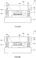
Fig. 5 (a) and Fig. 5(b) are views for explaining apressure applying unit 102 of anembodiment 2.Fig. 5(a) is a cross-sectional side view of thepressure applying unit 102 and an assembledbody 20 during a pressure non-applying time, andFig. 5 (b) is a cross-sectional side view of thepressure applying unit 102 and the assembledbody 20 during a pressure applying time. -
Fig. 6(a) and Fig. 6(b) are views for explaining apressure applying unit 104 according to a modification.Fig. 6(a) is a cross-sectional side view of thepressure applying unit 104 and an assembledbody 22 during a pressure non-applying time, andFig. 6(b) is a cross-sectional side view of thepressure applying unit 104 and the assembledbody 22 during a pressure applying time. -
Fig. 7 is a view for explaining a first step in a conventional method of manufacturing a bonded body.Fig. 7 is a cross-sectional side view substantially equal toFig. 1(b) showing a cross section of the bonded body. The same goes for followingFig. 8 and Fig. 9 . -
Fig. 8 is a view for explaining a second step in the conventional method of manufacturing a bonded body. -
Fig. 9 is a view for explaining a third step in the conventional method of manufacturing a bonded body. - Hereinafter, a pressure applying unit of the present invention is described by reference to embodiments shown in the drawings.
- A
pressure applying unit 100 according to anembodiment 1 is a pressure applying unit which is used in baking ametal particle paste 4 by heating an assembledbody 20 where anelectronic part 2 is arranged on asubstrate 1 with themetal particle paste 4 interposed therebetween while applying a pressure to the assembledbody 20 using a pair ofheating parts body 20 is substantially equal to the assembledbody 20 described previously (seeFig. 7 ) and hence, the repetition of the illustration and the explanation of the assembledbody 20 is omitted. - The
substrate 1, theelectronic part 2 and themetal particle paste 4 are described in detail. - In this specification, "substrate" means a part on which an electronic part is mounted.
- The
substrate 1 mounts theelectronic part 2 thereon. Thesubstrate 1 of theembodiment 1 is, for example, a printed circuit board where a conductor pattern is formed on a body made of a non-conductive material. As a material for forming thesubstrate 1, a material which has resistance to a sintering temperature of the metal particle paste 4 (for example, 300°C although the sintering temperature depends on a kind of material) can be used (for example, a resin or a ceramic having heat resistance is used for forming the body, and metal is used for forming the conductor pattern). - The substrate to which the present invention is applicable may be a DCB (Direct Copper Bond) substrate or a lead frame. Further, it is sufficient that the substrate to which the present invention is applicable is a substrate on which an electronic part can be mounted. For example, the substrate may be a silicon chip. That is, the present invention is also applicable to the connection between a silicon chip and a conductive connector.
- In this specification, "electronic part" means a part which is used in an electric product and is particularly required to be electrically connected to the substrate.
- The
electronic part 2 is a semiconductor element, for example. - As an electronic part, besides the above-mentioned semiconductor element (for example, a semiconductor chip on which an integrated circuit is mounted), an electric motor, a resistor, a capacitor, a piezoelectric element, a connector, a switch, an antenna, and a conductive connector can be exemplified. The pressure applying unit of the present invention is particularly preferably applicable to a case where a bonded body formed by bonding at least one semiconductor element and a substrate to each other, that is, a semiconductor device is manufactured. Although the number of
electronic parts 2 used in theembodiment 1 is one, the present invention is also applicable to the case where two or more electronic parts are used. When two or more electronic parts are used, the electronic parts may be formed of one kind of electronic part, or may be formed of two or more kinds of electronic parts. - The
metal particle paste 4 is a conductive paste of a low-temperature sintering type which contains nano-sized or submicron-sized metal particles in a solvent, and makes use of a low-temperature sintering phenomenon and high surface activity of the metal particles. Themetal particle paste 4 contains metal particles, an organic dispersion material, an organic dispersion material capturing material, and a volatile organic solvent, for example. - As the metal particles, metal nanoparticles (for example, metal particles having an average diameter of approximately 100nm or less), metal submicron particles (for example, metal particles having an average diameter which falls within a range of from approximately 0.1µm to approximately 1µm), or metal particles formed of both the metal nanoparticles and the metal submicron particles can be used. As a material for forming metal particles, silver, gold or copper can be used, for example. The organic dispersion material covers surfaces of metal particles at a room temperature, and has a function of holding the metal particles in an independently dispersed state. The organic dispersion material capturing material reacts with the organic dispersion material which covers the metal particles at a high temperature and performs a function of removing the organic dispersion material from surfaces of the metal particles. The volatile organic solvent has a function of capturing a chemical reaction product formed between the organic dispersion material and the organic dispersion material capturing material and also performs a function of releasing the chemical reaction product to the outside of a system in the form of a gas.
- Next, the configuration of the
pressure applying unit 100 according to theembodiment 1 is explained. - As shown in
Fig. 2 (a) and Fig. 2 (b) , thepressure applying unit 100 includes a pair of transferringmembers members 130, anddistance adjusting mechanisms 140. - In the explanation made hereinafter, assume a time during which a pressure is not applied to the pressure applying unit 100 (see
Fig. 3(a) ) as pressure non-applying time, and assume a time during which predetermined pressure is applied to the pressure applying unit 100 (seeFig. 4(a) ) as a pressure applying time. - In this specification, "predetermined pressure" means pressure which is applied to the
pressure applying unit 100 in sintering themetal particle paste 4. - The pair of transferring
members member 110 which is brought into contact with thesubstrate 1 at least during a pressure applying time and a plate-likesecond transferring member 120 which is brought into contact with the electronic part at least during a pressure applying time. The pair of transferringmembers body 20 by sandwiching the assembledbody 20 therebetween in sintering themetal particle paste 4. - The
first transferring member 110 and thesecond transferring member 120 are made of a ceramic or metal, for example. - The
first transferring member 110 and thesecond transferring member 120 are respectively formed of a plate-like member having a rectangular shape as viewed in a top plan view. In other words, the first transferringmember 110 and thesecond transferring member 120 are respectively formed of a member having a rectangular parallelepiped shape. - In this specification, "plate-like" means not only a completely plate-like shape (only a rectangular parallelepiped shape and a circular columnar shape) but also an approximately plate-like shape as a whole. That is, the transferring member used in the pressure applying unit of the present invention is not limited to the above-mentioned shape, and it is possible to use a transferring member having a shape corresponding to an assembled body or a method of manufacturing a bonded body (for example, assuming a case where a tray on which the pressure applying unit of the present invention is placed exists and an opening portion or a convex/concave portion for fixing the position of the pressure applying unit is formed on the tray, a transferring member having a projecting portion or a cutout whose shape conforms to a shape of the opening portion or the convex/concave portion). Further, a transferring member used in the pressure applying unit of the present invention may include, besides a plate-like member, other members (for example, a spacer, an abutting member having a shape corresponding to a shape of the electronic part and the like) (for example, see an
embodiment 2 and a modification described later). - Guide
member receiving holes 122 which correspond to theguide members 130 respectively are formed in thesecond transferring member 120. In theembodiment 1, four guidemember receiving holes 122 in total are formed on four corners of thesecond transferring member 120 such that one guidemember receiving hole 122 is formed in each corner of thesecond transferring member 120. Thesecond transferring member 120 can move along theguide members 130 respectively inserted into the guide member receiving holes 122. - In the technical feature of "the second transferring member can move along the guide members respectively inserted into the guide member receiving holes", "move" means the relative movement of the second transferring member relative to the first transferring member. Depending on the manner of applying pressure to the pressure applying unit, there may be a case where the second transferring member is held stationary and the first transferring member and the guide members are movable as viewed from the outside (for example, a case where a pressure is applied go the pressure applying unit and the assembled body by moving the heating part disposed on a lower side in a direction toward the heating part disposed on an upper side). Also in this case, the second transferring member is moved relative to the first transferring member and hence, such movement is included in the above-mentioned movement.
- The guide
member receiving hole 122 is a through hole having a circular shape as viewed in a top plan view in conformity with a shape of the guide member 130 (a circular columnar shape as described later). The shape of the guide member receiving hole of the present invention is not limited to a circular shape as viewed in a top plan view, and it is sufficient for the guide member receiving hole to have a shape in conformity with a shape of the guide member. Further, the guide member receiving hole may be a hole (a bottomed hole) other than the through hole. - The
guide members 130 connect the pair of transferringmembers member 110 and thesecond transferring member 120 while keeping parallelism of one transferring member with the other transferring member. In theembodiment 1, theguide members 130 allow the movement of thesecond transferring member 120 while keeping parallelism of thesecond transferring member 120 with the first transferring member 110 (the expression "allow the movement of" being also made by an expression "guide"). From a viewpoint of ensuring stability of the movement of the transferring member, it is preferable for the pressure applying unit of the present invention to include two or more guide members, and more preferably, four or more guide members. - The
pressure applying unit 100 includes two or more guide members, specifically, four guide members. When theguide members 130 are viewed in a direction perpendicular to a surface of the first transferringmember 110 on which thesubstrate 1 is arranged, theguide members 130 are arranged at apexes of a predetermined quadrangular shape surrounding a place where the assembledbody 20 is to be arranged (see a broken line indicated by symbol Q inFig. 2 (a) ). In theembodiment 1, fourguide members 130 in total are arranged on four corners of the first transferringmember 110 such that oneguide member 130 is arranged in each corner of the first transferringmember 110. - One end portions of the
guide members 130 are respectively fixed to the first transferringmember 110. The other end portions of theguide members 130 on a side opposite to one end portions are arranged in the inside of the guidemember receiving holes 122 respectively during a pressure applying time (seeFig. 4(a) and Fig. 4(b) ). - The
guide members 130 are made of metal such as stainless steel, for example. - In the
embodiment 1, all fourguide members 130 have a circular columnar shape. The number of guide members used in the present invention is not limited to four, and may be 1 to 3 or 5 or more provided that the guide members can achieve their purpose. Further, the shape of the guide members of the present invention is not limited to a circular columnar shape, and the shape of the guide members may be other shapes (to be more specific, a prismatic shape, an elliptical shape, a flat plate shape, a corrugated shape, an L shape or a T shape) provided that the guide members can achieve their purpose. - The
distance adjusting mechanism 140 is a mechanism for adjusting a distance between the first transferringmember 110 and thesecond transferring member 120. In a state where the assembledbody 20 is arranged between the pair of transferringmembers distance adjusting mechanism 140 makes the first transferringmember 110 or thesecond transferring member 120 separated from the assembledbody 20 during a pressure non-applying time, and brings both the first transferringmember 110 and thesecond transferring member 120 into contact with the assembledbody 20 during a pressure applying time. Thedistance adjusting mechanism 140 includes a resilient member which extends during a pressure non-applying time, and shrinks during a pressure applying time. The resilient member is formed of a coil spring, and is arranged using theguide member 130 as a shaft. - The distance adjusting mechanism of the present invention is not limited to the resilient member, and the distance adjusting mechanism may be a member which is configured to shrink when a pressurizing state of the distance adjusting mechanism is shifted to a pressure applying time from a pressure non-applying time but does not extend when the pressurizing state is shifted from the pressure applying time to the pressure non-applying time (for example, a multi-stage pipe having the telescopic structure).
- Further, the resilient member of the present invention is not limited to a coil spring, a member which can withstand a temperature at the time of sintering a metal particle paste may be used. As a specific example of the resilient member other than the coil spring, a leaf spring and heat resistance rubber can be named.
- The distance adjusting mechanism of the present invention may include a constitutional element other than the resilient member (for example, a member which supports the resilient member or a member which reinforces the resilient member).
- In this specification, the expression "arranged using the guide member as a shaft" is used with respect to the coil spring. This expression means that the coil spring is arranged in a state where the guide member is disposed in a hollow portion of the coil spring.
- The resilient member of the present invention may be arranged at a position different from a position where the guide member is arranged. Further, the resilient member of the present invention may be arranged using a constitutional element other than the guide member as a shaft. Only the resilient member may be arranged (without using a shaft).
- Next, a method of manufacturing a bonded body using the
pressure applying unit 100 according to theembodiment 1 is simply explained. - The method of manufacturing the above-mentioned bonded body includes following steps, that is, a first step S10, a second step S20, and a third step S30 in this order.
- The first step S10 is a step where the assembled
body 20 is prepared. This step is substantially equal to the step shown inFig. 7 and hence, the illustration of the step is omitted. - The first step S10 can be performed such that, for example, after preparing the
substrate 1, theelectronic part 2 and themetal particle paste 4, themetal particle paste 4 is applied by coating to a predetermined place of the substrate 1 (for example, contact points with the electronic part 2), and theelectronic part 2 is arranged on the place. - As shown in
Fig. 3(a) and Fig. 3(b) , the second step S20 is a step where the assembledbody 20 is sandwiched between the pair of transferringmembers pressure applying unit 100 and, thereafter, the assembledbody 20 is arranged between the pair ofheating parts pressure applying unit 100. - In the second step S20 of the
embodiment 1, although the assembledbody 20 and thepressure applying unit 100 are directly arranged on theheating part 1000, the assembledbody 20 and thepressure applying unit 100 may be arranged between the pair ofheating parts 1000, 1002 (that is, in a spaced-apart manner from the heating part 1000). - As shown in
Fig. 4(b) , the third step S30 is a step where theheating part 1002 disposed on an upper side is moved toward theheating part 1000, and themetal particle paste 4 is baked by heating the assembledbody 20 together with thepressure applying unit 100 using a pair ofheating parts body 20 thus manufacturing the bondedbody 10. - In the third step S30 of the
embodiment 1, theheating part 1002 is moved. However, theheating part 1000 may be moved or bothheating parts - Hereinafter, advantageous effects of the
pressure applying unit 100 according to theembodiment 1 are explained. - According to the
pressure applying unit 100 of theembodiment 1, the pressure applying unit includes the pair of transferringmembers - Further, according to the
pressure applying unit 100 of theembodiment 1, thepressure applying unit 100 suppresses unintended heat conduction to themetal particle paste 4 from theheating parts - Accordingly, the
pressure applying unit 100 according to theembodiment 1 forms a pressure applying unit which can be used in a method of manufacturing a bonded body capable of suppressing the lowering of bonding property between thesubstrate 1 and theelectronic part 2 and capable of preventing remarkable lowering of productivity of a bonded body. - Further, the
pressure applying unit 100 of theembodiment 1 includes theguide member 130. Accordingly, even when the pair of transferring members is moved due to applying of pressure, parallelism between the pair of transferring members can be kept. As a result, it is possible to suppress the occurrence of irregularities in bonding strength between the substrate and the electronic part depending on places. - The
pressure applying unit 100 of theembodiment 1 includes thedistance adjusting mechanism 140. Accordingly, it is possible to prevent the transfer of vibrations or an impact applied to the pair of transferring members to the assembled body during a pressure non-applying time. As a result, it is possible to reduce the displacement of the positional relationship between the substrate and the electronic part. - Further, in the
pressure applying unit 100 of theembodiment 1, thedistance adjusting mechanism 140 includes the resilient member which extends during the pressure non-applying time, and shrinks during the pressure applying time. Accordingly, when applying of pressure to the pressure applying unit is released after baking a metal particle paste, the pair of transferring members can be automatically spaced apart from each other and, as a result, the assembled body can be easily taken out. - Further, in the
pressure applying unit 100 of theembodiment 1, the resilient member is formed of a coil spring, and is arranged using the guide member as a shaft. Accordingly, the distance adjusting mechanism can be realized with the simple structure. - Further, in the
pressure applying unit 100 of theembodiment 1, one end portions of theguide members 130 are fixed to the first transferringmember 110, the guidemember receiving holes 122 which conform to theguide members 130 are formed in thesecond transferring member 120, and thesecond transferring member 120 is movable along theguide members 130 inserted into the guidemember receiving hole 122. Accordingly, it is possible to move the second transferring member using the simple configuration with high accuracy. - Further, in the
pressure applying unit 100 of theembodiment 1, the other end portions of theguide members 130 are disposed in the guidemember receiving holes 122 during the pressure applying time. Accordingly, it is possible to prevent the guide members from coming into contact with the heating parts and hence, it is possible to apply pressure to the pressure applying unit in a stable manner. - Further, in the
pressure applying unit 100 of theembodiment 1, thepressure applying unit 100 includes four ormore guide members 130, and theguide members 130 are arranged at least at apexes of a predetermined quadrangular shape Q surrounding a place where the assembledbody 20 is to be arranged. Accordingly, the parallelism between the pair of transferring members can be kept with high accuracy by four guide members arranged at apexes of a predetermined quadrangular shape. - A
pressure applying unit 102 of anembodiment 2 has substantially the same configuration as thepressure applying unit 100 of theembodiment 1. However, thepressure applying unit 102 is different from thepressure applying unit 100 of theembodiment 1 with respect to the configuration of the second transferring member and the configuration of the guide members . That is, as shown inFig. 5(b) , in thepressure applying unit 102 of theembodiment 2, the other end portion of theguide member 132 disposed on a side opposite to one end portion of theguide member 132 is configured to project from the guidemember receiving hole 122 toward a side of thesecond transferring member 150 on a side opposite to the first transferringmember 110, and thesecond transferring member 150 further includes aspacer 156 having a thickness larger than a length by which theguide member 132 projects from the guidemember receiving hole 122 on a side of thesecond transferring member 150 where theguide member 132 projects. - The
second transferring member 150 includes amember 154 having a rectangular parallelepiped member and thespacer 156. - The
member 154 having a rectangular parallelepiped shape is a member substantially equal to the member having a rectangular parallelepiped shape which forms thesecond transferring member 120 of theembodiment 1. - The
spacer 156 is made of the same material as themember 154 having a rectangular parallelepiped shape. Thespacer 156 may be completely fixed to themember 154 having a rectangular parallelepiped shape or may be detachably mounted on themember 154 having a rectangular parallelepiped shape. Thespacer 156 has a rectangular parallelepiped shape and is one size smaller than themember 154 having a rectangular parallelepiped shape. Although onespacer 156 is used in theembodiment 2, a plurality ofspacers 156 may be used. When a plurality ofspacers 156 are used, onespacer 156 may be made to overlap to anotherspacer 156. Further, in theembodiment 2, although thespacer 156 has a rectangular parallelepiped shape and is one size smaller than themember 154 having a rectangular parallelepiped shape. However, the spacer of the present invention may have a shape (a circular columnar shape, a prismatic shape or the like) other than the above-mentioned shape. Further, the spacer may be formed of a solid body or may be formed of a hollow body having a space in the inside thereof. - The
guide member 132 has substantially the same configuration as theguide member 130 of theembodiment 1. However, theguide member 132 is longer than theguide member 130. - As described above, the
pressure applying unit 102 of theembodiment 2 differs from thepressure applying unit 100 of theembodiment 1 with respect to the configuration of the second transferring member and the configuration of the guide member. However, thepressure applying unit 102 of theembodiment 2 is a pressure applying unit which is used in a method of manufacturing a bonded body which includes the pair of transferring members, can suppress the lowering of bonding property between the substrate and the electronic part in the same manner as thepressure applying unit 100 according to theembodiment 1 for suppressing unintended heat conduction to the metal particle paste from the heating part, and can prevent remarkable lowering of productivity of assembled bodies. - Further, according to the
pressure applying unit 102 according to theembodiment 2, thesecond transferring member 150 includes thespacer 156 and hence, it is possible to prevent the guide member from coming into contact with the heating part whereby it is possible to stably apply pressure to the pressure applying unit. - The
pressure applying unit 102 according to theembodiment 2 basically has substantially the same configuration as thepressure applying unit 100 according to theembodiment 1 except for the configuration of the second transferring member and the configuration of the guide member. Accordingly, thepressure applying unit 102 according to theembodiment 2 can acquire advantageous effects which correspond to the advantageous effects out of the advantageous effects which thepressure applying unit 100 according to theembodiment 1 can acquire. - Although the present invention has been explained heretofore by reference to the above-mentioned respective embodiments, the present invention is not limited to the above-mentioned respective embodiments. Various modifications are conceivable without departing from the gist of the present invention. For example, the following modifications are also conceivable.
- (1) The number, materials, shapes, positions, sizes and the like of the constitutional elements described in the above-mentioned respective embodiments are merely examples, and can be changed within a range where the advantageous effects of the present invention are not impaired.
- (2) In the above-mentioned
embodiment 1, the present invention has been explained using the first transferringmember 110 and thesecond transferring member 120 which are respectively formed of a member having a rectangular parallelepiped shape. However, the present invention is not limited to such a configuration. As shown inFig. 6 (a) and Fig. 6(b) , apressure applying unit 104 according to a modification is a pressure applying unit which is used in baking ametal particle paste 4 by heating an assembledbody 22 which is formed by arranging anelectronic part 5 on asubstrate 1 with themetal particle paste 4 interposed therebetween using a pair of heating parts while applying a pressure to the assembledbody 22. Theelectronic part 5 is basically substantially equal to theelectronic part 2 of theembodiment 1. However, theelectronic part 5 has a projecting portion on a side thereof opposite to asubstrate 1 side. Asecond transferring member 160 of thepressure applying unit 104 basically has substantially the same configuration as thesecond transferring member 120 of theembodiment 1. However, thesecond transferring member 160 includes amember 164 having a rectangular parallelepiped shape and an abuttingmember 166. Themember 164 having a parallelepiped shape is a member substantially equal to the member having a rectangular parallelepiped shape which forms thesecond transferring member 120 of theembodiment 1, and the abuttingmember 166 is a member having a recessed portion on afirst transferring member 110 side thereof. The recessed portion of the abuttingmember 166 corresponds to the projecting portion of theelectronic part 5. For example, as shown in the modification, the transferring member used in the pressure applying unit according to the present invention may have a member other than the plate-like member or the spacer. - 1: substrate, 2, 5: electronic part, 3: baked metal particle paste, 4: metal particle paste, 10: bonded body, 20, 22: assembled body, 100, 102, 104: pressure applying unit, 110: first transferring member, 120, 150, 160: second transferring member, 122: guide member receiving hole, 130, 132: guide member, 140: distance adjusting mechanism, 154, 164: member having rectangular parallelepiped shape, 156: spacer, 166: abutting member, 1000, 1002: heating part, Q: predetermined quadrangular shape
Claims (7)
- A pressure applying unit used in baking a metal particle paste of an assembled body formed by arranging an electronic part on a substrate with the metal particle paste interposed therebetween by heating the assembled body while applying pressure to the assembled body using a pair of heating parts, wherein
assuming a time during which pressure is not applied to the pressure applying unit as a pressure non-applying time and a time during which predetermined pressure is applied to the pressure applying unit as a pressure applying time,
the pressure applying unit comprises:a pair of transferring members which is constituted of a plate-like first transferring member being in contact with the substrate at least during the pressure applying time and a plate-like second transferring member being in contact with the electronic part at least during the pressure applying time and transfers pressure and heat to the assembled body by sandwiching the assembled body therebetween in sintering the metal particle paste;a guide member which connects the pair of transferring members to each other, and allows the movement of at least one transferring member out of the first transferring member and the second transferring member while keeping parallelism of one transferring member with the other transferring member; anda distance adjusting mechanism for adjusting a distance between the first transferring member and the second transferring member, the distance adjusting mechanism being configured to, in a state where the assembled body is arranged between the pair of transferring members, make the first transferring member or the second transferring member separated from the assembled body during the pressure non-applying time and brings both the first transferring member and the second transferring member into contact with the assembled body during the pressure applying time. - The pressure applying unit according to claim 1, wherein the distance adjusting mechanism includes a resilient member which extends during the pressure non-applying time, and shrinks during the pressure applying time.
- The pressure applying unit according to claim 2, wherein the resilient member is formed of a coil spring, and is arranged using the guide member as a shaft.
- The pressure applying unit according to any one of claims 1 to 3, wherein one end portion of the guide member is fixed to the first transferring member,
a guide member receiving hole which conforms to the guide member is formed in the second transferring member, and
the second transferring member is movable along the guide member inserted into the guide member receiving hole. - The pressure applying unit according to claim 4, wherein the other end portion of the guide member disposed on a side opposite to said one end portion of the guide member is disposed in the guide member receiving hole during the pressure applying time.
- The pressure applying unit according to claim 4, wherein the other end portion of the guide member disposed on a side opposite to said one end portion of the guide member is configured to project from the guide member receiving hole toward a side of the second transferring member on a side opposite to the first transferring member during the pressure applying time, and
the second transferring member further includes a spacer having a thickness larger than a length by which the guide member projects from the guide member receiving hole on a side of the second transferring member where the guide member projects. - The pressure applying unit according to any one of claims 1 to 6, wherein the pressure applying unit includes four or more guide members, and when the guide members are viewed in a direction perpendicular to a surface of the first transferring member on which the substrate is arranged, the guide members are arranged at least at apexes of a predetermined quadrangular shape surrounding a place where the assembled body is to be arranged.
Applications Claiming Priority (1)
| Application Number | Priority Date | Filing Date | Title |
|---|---|---|---|
| PCT/JP2015/060297 WO2016157465A1 (en) | 2015-03-31 | 2015-03-31 | Pressurization unit |
Publications (1)
| Publication Number | Publication Date |
|---|---|
| EP3279929A1 true EP3279929A1 (en) | 2018-02-07 |
Family
ID=57004097
Family Applications (1)
| Application Number | Title | Priority Date | Filing Date |
|---|---|---|---|
| EP15880665.3A Withdrawn EP3279929A1 (en) | 2015-03-31 | 2015-03-31 | Pressurization unit |
Country Status (5)
| Country | Link |
|---|---|
| US (1) | US9956643B2 (en) |
| EP (1) | EP3279929A1 (en) |
| JP (1) | JP6129353B2 (en) |
| CN (1) | CN106605296A (en) |
| WO (1) | WO2016157465A1 (en) |
Families Citing this family (12)
| Publication number | Priority date | Publication date | Assignee | Title |
|---|---|---|---|---|
| DE102014114093B4 (en) | 2014-09-29 | 2017-03-23 | Danfoss Silicon Power Gmbh | Method for low-temperature pressure sintering |
| DE102014114097B4 (en) * | 2014-09-29 | 2017-06-01 | Danfoss Silicon Power Gmbh | Sintering tool and method for sintering an electronic assembly |
| WO2016134000A1 (en) | 2015-02-17 | 2016-08-25 | H.C. Starck Inc. | Racks for high-temperature metal processing |
| US11227779B2 (en) * | 2017-09-12 | 2022-01-18 | Asm Technology Singapore Pte Ltd | Apparatus and method for processing a semiconductor device |
| KR102455439B1 (en) * | 2017-10-26 | 2022-10-14 | 엘지전자 주식회사 | Sintering apparatus for power module |
| CN108067721A (en) * | 2017-11-27 | 2018-05-25 | 中国电子科技集团公司第十八研究所 | An integrated welding device for a semiconductor refrigerator |
| KR102456174B1 (en) | 2018-02-14 | 2022-10-19 | 삼성전자주식회사 | Compression device and manufacturing method of light source module using the same |
| US11152328B2 (en) * | 2018-12-13 | 2021-10-19 | eLux, Inc. | System and method for uniform pressure gang bonding |
| KR102719349B1 (en) * | 2019-09-27 | 2024-10-18 | 삼성전자주식회사 | Bonding head, die bonding apparatus including the same and method of manufacturing semiconductor package using the same |
| CN113458580A (en) * | 2020-03-30 | 2021-10-01 | 超众科技股份有限公司 | Joining device |
| DE102021118948B3 (en) * | 2021-07-22 | 2022-06-09 | Semikron Elektronik Gmbh & Co. Kg | Apparatus and method for pressurized sintering |
| CN119188038A (en) * | 2024-09-20 | 2024-12-27 | 浙江工业大学 | Metal-composite material interface temperature joint welding device and welding method |
Family Cites Families (18)
| Publication number | Priority date | Publication date | Assignee | Title |
|---|---|---|---|---|
| US3151862A (en) | 1961-08-08 | 1964-10-06 | Budd Co | Gripping device for chuck jaws |
| US5592021A (en) * | 1995-04-26 | 1997-01-07 | Martin Marietta Corporation | Clamp for securing a power device to a heatsink |
| JP4718734B2 (en) * | 2001-09-12 | 2011-07-06 | 日機装株式会社 | Circuit element mounting method |
| JP4525571B2 (en) * | 2005-11-24 | 2010-08-18 | 住友電気工業株式会社 | Wafer holder, heater unit on which it is mounted, and wafer prober |
| JP4635972B2 (en) * | 2006-06-29 | 2011-02-23 | 株式会社ニコン | Load lock device, method using the same, and wafer bonding system |
| JP4943936B2 (en) * | 2007-05-10 | 2012-05-30 | 芝浦メカトロニクス株式会社 | Electronic component mounting apparatus and mounting method |
| JP2010034423A (en) * | 2008-07-30 | 2010-02-12 | Fujitsu Ltd | Pressure-heating apparatus and method |
| JP2010114208A (en) | 2008-11-05 | 2010-05-20 | Nikon Corp | Cooling apparatus and joining system |
| US8151852B2 (en) | 2009-06-30 | 2012-04-10 | Twin Creeks Technologies, Inc. | Bonding apparatus and method |
| JP2010258127A (en) * | 2009-04-23 | 2010-11-11 | Nec Corp | Semiconductor component mounting apparatus and semiconductor component mounting method |
| US9393633B2 (en) | 2009-09-01 | 2016-07-19 | Globalfoundries Inc. | Method of joining a chip on a substrate |
| JP5705467B2 (en) | 2010-06-25 | 2015-04-22 | 新電元工業株式会社 | Semiconductor device bonding method and semiconductor device |
| JP5892682B2 (en) * | 2011-04-27 | 2016-03-23 | アピックヤマダ株式会社 | Joining method |
| TWI564106B (en) | 2011-03-28 | 2017-01-01 | 山田尖端科技股份有限公司 | Bonding device and joining method |
| JP2012248879A (en) * | 2012-08-10 | 2012-12-13 | Hitachi High-Tech Instruments Co Ltd | Component mounting apparatus |
| FR3005895B1 (en) | 2013-05-27 | 2015-06-26 | Commissariat Energie Atomique | METHOD FOR ASSEMBLING TWO DIFFERENT SUBSTRATES VIA A DUCTILE INTERMEDIATE LAYER |
| JP6206021B2 (en) | 2013-09-12 | 2017-10-04 | 三菱電機株式会社 | Power semiconductor device manufacturing method and power semiconductor device |
| DE102014103013B4 (en) | 2014-03-06 | 2017-09-21 | Infineon Technologies Ag | Method for producing a dried paste layer, method for producing a sintered connection and continuous system for carrying out the method |
-
2015
- 2015-03-31 EP EP15880665.3A patent/EP3279929A1/en not_active Withdrawn
- 2015-03-31 US US15/122,925 patent/US9956643B2/en active Active
- 2015-03-31 JP JP2015555330A patent/JP6129353B2/en active Active
- 2015-03-31 WO PCT/JP2015/060297 patent/WO2016157465A1/en not_active Ceased
- 2015-03-31 CN CN201580045120.6A patent/CN106605296A/en active Pending
Also Published As
| Publication number | Publication date |
|---|---|
| CN106605296A (en) | 2017-04-26 |
| JP6129353B2 (en) | 2017-05-17 |
| US9956643B2 (en) | 2018-05-01 |
| WO2016157465A1 (en) | 2016-10-06 |
| JPWO2016157465A1 (en) | 2017-04-27 |
| US20170066075A1 (en) | 2017-03-09 |
Similar Documents
| Publication | Publication Date | Title |
|---|---|---|
| US9956643B2 (en) | Pressure applying unit | |
| US10037903B2 (en) | Bonding device, bonding method and pressure applying unit | |
| US7834441B2 (en) | Multilayer substrate and method of manufacturing the same | |
| KR101364486B1 (en) | Test carrier | |
| US20120056640A1 (en) | Compliant printed circuit semiconductor tester interface | |
| US20130210276A1 (en) | Electrical interconnect ic device socket | |
| US10083844B2 (en) | Method of manufacturing bonded body | |
| KR20060132708A (en) | Apparatus incorporating small-feature-size and large-feature-size components and method for making same | |
| CN119028853A (en) | Method of forming a semiconductor device | |
| JP5186449B2 (en) | Device having power semiconductor module and method of manufacturing the same | |
| US9106006B2 (en) | Connector having an anisotropic conductive film | |
| KR20140100488A (en) | Connection device, method for manufacturing connection structure, method for manufacturing stacked chip component and method for mounting electronic component | |
| JP2008192895A (en) | Electrical component connection device | |
| EP3132662B1 (en) | Method to align surface mount packages for thermal enhancement | |
| KR101609264B1 (en) | Electronic components embedded substrate and method for manufacturing thereof | |
| US20170069592A1 (en) | Transferring member and pressure applying unit | |
| CN113519043B (en) | Pressure sintering apparatus and method for manufacturing electronic components by pressure-assisted low temperature sintering process | |
| JP4795067B2 (en) | Manufacturing method of substrate with electrical components | |
| JP2016006846A (en) | Wiring board and electronic apparatus | |
| JPWO2018029983A1 (en) | Bonding device | |
| JP2004538602A (en) | Removable fastening means for land grid array connector | |
| JP2015109394A (en) | Semiconductor device and manufacturing method thereof |
Legal Events
| Date | Code | Title | Description |
|---|---|---|---|
| PUAI | Public reference made under article 153(3) epc to a published international application that has entered the european phase |
Free format text: ORIGINAL CODE: 0009012 |
|
| 17P | Request for examination filed |
Effective date: 20160808 |
|
| AK | Designated contracting states |
Kind code of ref document: A1 Designated state(s): AL AT BE BG CH CY CZ DE DK EE ES FI FR GB GR HR HU IE IS IT LI LT LU LV MC MK MT NL NO PL PT RO RS SE SI SK SM TR |
|
| AX | Request for extension of the european patent |
Extension state: BA ME |
|
| DAV | Request for validation of the european patent (deleted) | ||
| DAX | Request for extension of the european patent (deleted) | ||
| STAA | Information on the status of an ep patent application or granted ep patent |
Free format text: STATUS: THE APPLICATION HAS BEEN WITHDRAWN |
|
| 18W | Application withdrawn |
Effective date: 20181010 |