EP3279758A1 - Condition determination system, condition determination method, decision-making support system, computer program, and storage medium - Google Patents
Condition determination system, condition determination method, decision-making support system, computer program, and storage medium Download PDFInfo
- Publication number
- EP3279758A1 EP3279758A1 EP16772664.5A EP16772664A EP3279758A1 EP 3279758 A1 EP3279758 A1 EP 3279758A1 EP 16772664 A EP16772664 A EP 16772664A EP 3279758 A1 EP3279758 A1 EP 3279758A1
- Authority
- EP
- European Patent Office
- Prior art keywords
- data
- display
- power source
- operation condition
- power
- Prior art date
- Legal status (The legal status is an assumption and is not a legal conclusion. Google has not performed a legal analysis and makes no representation as to the accuracy of the status listed.)
- Withdrawn
Links
Images








Classifications
-
- G—PHYSICS
- G06—COMPUTING OR CALCULATING; COUNTING
- G06N—COMPUTING ARRANGEMENTS BASED ON SPECIFIC COMPUTATIONAL MODELS
- G06N5/00—Computing arrangements using knowledge-based models
- G06N5/04—Inference or reasoning models
- G06N5/045—Explanation of inference; Explainable artificial intelligence [XAI]; Interpretable artificial intelligence
-
- G—PHYSICS
- G05—CONTROLLING; REGULATING
- G05B—CONTROL OR REGULATING SYSTEMS IN GENERAL; FUNCTIONAL ELEMENTS OF SUCH SYSTEMS; MONITORING OR TESTING ARRANGEMENTS FOR SUCH SYSTEMS OR ELEMENTS
- G05B19/00—Program-control systems
- G05B19/02—Program-control systems electric
- G05B19/418—Total factory control, i.e. centrally controlling a plurality of machines, e.g. direct or distributed numerical control [DNC], flexible manufacturing systems [FMS], integrated manufacturing systems [IMS] or computer integrated manufacturing [CIM]
-
- G—PHYSICS
- G05—CONTROLLING; REGULATING
- G05B—CONTROL OR REGULATING SYSTEMS IN GENERAL; FUNCTIONAL ELEMENTS OF SUCH SYSTEMS; MONITORING OR TESTING ARRANGEMENTS FOR SUCH SYSTEMS OR ELEMENTS
- G05B23/00—Testing or monitoring of control systems or parts thereof
- G05B23/02—Electric testing or monitoring
- G05B23/0205—Electric testing or monitoring by means of a monitoring system capable of detecting and responding to faults
- G05B23/0259—Electric testing or monitoring by means of a monitoring system capable of detecting and responding to faults characterized by the response to fault detection
- G05B23/0267—Fault communication, e.g. human machine interface [HMI]
- G05B23/0272—Presentation of monitored results, e.g. selection of status reports to be displayed; Filtering information to the user
-
- G—PHYSICS
- G06—COMPUTING OR CALCULATING; COUNTING
- G06Q—INFORMATION AND COMMUNICATION TECHNOLOGY [ICT] SPECIALLY ADAPTED FOR ADMINISTRATIVE, COMMERCIAL, FINANCIAL, MANAGERIAL OR SUPERVISORY PURPOSES; SYSTEMS OR METHODS SPECIALLY ADAPTED FOR ADMINISTRATIVE, COMMERCIAL, FINANCIAL, MANAGERIAL OR SUPERVISORY PURPOSES, NOT OTHERWISE PROVIDED FOR
- G06Q10/00—Administration; Management
- G06Q10/06—Resources, workflows, human or project management; Enterprise or organisation planning; Enterprise or organisation modelling
- G06Q10/063—Operations research, analysis or management
- G06Q10/0631—Resource planning, allocation, distributing or scheduling for enterprises or organisations
-
- G—PHYSICS
- G06—COMPUTING OR CALCULATING; COUNTING
- G06Q—INFORMATION AND COMMUNICATION TECHNOLOGY [ICT] SPECIALLY ADAPTED FOR ADMINISTRATIVE, COMMERCIAL, FINANCIAL, MANAGERIAL OR SUPERVISORY PURPOSES; SYSTEMS OR METHODS SPECIALLY ADAPTED FOR ADMINISTRATIVE, COMMERCIAL, FINANCIAL, MANAGERIAL OR SUPERVISORY PURPOSES, NOT OTHERWISE PROVIDED FOR
- G06Q10/00—Administration; Management
- G06Q10/06—Resources, workflows, human or project management; Enterprise or organisation planning; Enterprise or organisation modelling
- G06Q10/063—Operations research, analysis or management
- G06Q10/0635—Risk analysis of enterprise or organisation activities
-
- G—PHYSICS
- G06—COMPUTING OR CALCULATING; COUNTING
- G06Q—INFORMATION AND COMMUNICATION TECHNOLOGY [ICT] SPECIALLY ADAPTED FOR ADMINISTRATIVE, COMMERCIAL, FINANCIAL, MANAGERIAL OR SUPERVISORY PURPOSES; SYSTEMS OR METHODS SPECIALLY ADAPTED FOR ADMINISTRATIVE, COMMERCIAL, FINANCIAL, MANAGERIAL OR SUPERVISORY PURPOSES, NOT OTHERWISE PROVIDED FOR
- G06Q50/00—Information and communication technology [ICT] specially adapted for implementation of business processes of specific business sectors, e.g. utilities or tourism
- G06Q50/06—Energy or water supply
-
- G—PHYSICS
- G21—NUCLEAR PHYSICS; NUCLEAR ENGINEERING
- G21D—NUCLEAR POWER PLANT
- G21D3/00—Control of nuclear power plant
- G21D3/08—Regulation of any parameters in the plant
-
- H—ELECTRICITY
- H02—GENERATION; CONVERSION OR DISTRIBUTION OF ELECTRIC POWER
- H02J—ELECTRIC POWER NETWORKS; CIRCUIT ARRANGEMENTS OR SYSTEMS FOR SUPPLYING OR DISTRIBUTING ELECTRIC POWER; SYSTEMS FOR STORING ELECTRIC ENERGY
- H02J13/00—Circuit arrangements for providing remote monitoring or remote control of equipment in a power distribution network
-
- H—ELECTRICITY
- H02—GENERATION; CONVERSION OR DISTRIBUTION OF ELECTRIC POWER
- H02J—ELECTRIC POWER NETWORKS; CIRCUIT ARRANGEMENTS OR SYSTEMS FOR SUPPLYING OR DISTRIBUTING ELECTRIC POWER; SYSTEMS FOR STORING ELECTRIC ENERGY
- H02J7/00—Circuit arrangements for charging or discharging batteries or for supplying loads from batteries
- H02J7/80—Circuit arrangements for charging or discharging batteries or for supplying loads from batteries including monitoring or indicating arrangements
- H02J7/82—Control of state of charge [SOC]
-
- H—ELECTRICITY
- H02—GENERATION; CONVERSION OR DISTRIBUTION OF ELECTRIC POWER
- H02J—ELECTRIC POWER NETWORKS; CIRCUIT ARRANGEMENTS OR SYSTEMS FOR SUPPLYING OR DISTRIBUTING ELECTRIC POWER; SYSTEMS FOR STORING ELECTRIC ENERGY
- H02J7/00—Circuit arrangements for charging or discharging batteries or for supplying loads from batteries
- H02J7/855—Circuit arrangements for charging or discharging batteries or for supplying loads from batteries with circuits adapted for supplying loads from the battery
-
- G—PHYSICS
- G05—CONTROLLING; REGULATING
- G05B—CONTROL OR REGULATING SYSTEMS IN GENERAL; FUNCTIONAL ELEMENTS OF SUCH SYSTEMS; MONITORING OR TESTING ARRANGEMENTS FOR SUCH SYSTEMS OR ELEMENTS
- G05B19/00—Program-control systems
- G05B19/02—Program-control systems electric
- G05B19/04—Program control other than numerical control, i.e. in sequence controllers or logic controllers
- G05B19/042—Program control other than numerical control, i.e. in sequence controllers or logic controllers using digital processors
- G05B19/0428—Safety, monitoring
-
- Y—GENERAL TAGGING OF NEW TECHNOLOGICAL DEVELOPMENTS; GENERAL TAGGING OF CROSS-SECTIONAL TECHNOLOGIES SPANNING OVER SEVERAL SECTIONS OF THE IPC; TECHNICAL SUBJECTS COVERED BY FORMER USPC CROSS-REFERENCE ART COLLECTIONS [XRACs] AND DIGESTS
- Y02—TECHNOLOGIES OR APPLICATIONS FOR MITIGATION OR ADAPTATION AGAINST CLIMATE CHANGE
- Y02E—REDUCTION OF GREENHOUSE GAS [GHG] EMISSIONS, RELATED TO ENERGY GENERATION, TRANSMISSION OR DISTRIBUTION
- Y02E30/00—Energy generation of nuclear origin
-
- Y—GENERAL TAGGING OF NEW TECHNOLOGICAL DEVELOPMENTS; GENERAL TAGGING OF CROSS-SECTIONAL TECHNOLOGIES SPANNING OVER SEVERAL SECTIONS OF THE IPC; TECHNICAL SUBJECTS COVERED BY FORMER USPC CROSS-REFERENCE ART COLLECTIONS [XRACs] AND DIGESTS
- Y02—TECHNOLOGIES OR APPLICATIONS FOR MITIGATION OR ADAPTATION AGAINST CLIMATE CHANGE
- Y02P—CLIMATE CHANGE MITIGATION TECHNOLOGIES IN THE PRODUCTION OR PROCESSING OF GOODS
- Y02P90/00—Enabling technologies with a potential contribution to greenhouse gas [GHG] emissions mitigation
- Y02P90/02—Total factory control, e.g. smart factories, flexible manufacturing systems [FMS] or integrated manufacturing systems [IMS]
Definitions
- the present invention relates to a condition determination system, a condition determination method, a decision-making support system, a computer program, and a storage medium.
- An object of an aspect of the present invention is to provide a condition determination system, a condition determination method, a computer program, and a storage medium, which enable prompt determination of a condition. Further, an object of another aspect of the present invention is to provide a decision-making support system that is able to effectively support decision-making by using the condition determination system.
- a condition determination system includes an operation condition data obtaining unit that obtains operation condition data indicating an operation condition of a facility, and a determination unit that determines, based on the operation condition data, a level of a phenomenon that occurs due to the operation condition of the facility.
- the obtainment of the operation condition data of the facility based on the operation condition data, the level of the phenomenon that occurs due to the operation condition of the facility is able to be determined. Thereby, the condition is able to be determined promptly.
- the condition determination system may include a storage unit that stores therein relation data indicating a relation between the operation condition of the facility and the level of the phenomenon.
- the determination unit may determine the level of the phenomenon, based on the operation condition data and the relation data.
- the operation condition data obtaining unit obtains the operation condition data of the facility, based on the relation data stored in the storage unit, the level of the phenomenon is able to be determined. Therefore, the condition is able to be determined promptly.
- the condition determination system may include a display control unit that generates display data, based on a result of the determination by the determination unit, and causes a display unit to display thereon the display data.
- the operation condition data obtaining unit may obtain the operation condition data of each of plural facilities, the determination unit may classify, based on the plural sets of operation condition data, the plural facilities into normal facilities and abnormal facilities, and the display control unit may cause the display device to display thereon the normal facilities and abnormal facilities in different designs.
- the facilities may include a storage battery power source
- the operation condition data may include remaining capacity data indicating a remaining battery capacity of the storage battery power source
- the display control unit may cause the display device to display thereon the remaining capacity data
- the power source with a large remaining battery capacity is able to be assigned appropriately.
- the facilities may include a storage battery power source
- the operation condition data may include power feedable time data indicating a time period, over which the storage battery power source is able to feed power
- the display control unit may cause the display device to display thereon the power feedable time data
- the power source with a long power feedable time period is able to be assigned appropriately.
- the time period, over which the storage battery power source is able to feed power is calculated based on necessary power of a device that the power is fed to.
- the facilities may include power sources, and the display control unit may cause the display device to display thereon the plural power sources correspondingly to capabilities of the power sources, respectively.
- the facilities may include power sources
- the condition determination system may include a characteristic data obtaining unit that obtains characteristic data of each of the plural power sources, the characteristic data including power feeding capabilities thereof, and a power source management unit that elects, based on necessary power data indicating power necessary for electric devices to operate and the characteristic data, the power source to be assigned to a specific electric device, and the display control unit may cause the display device to display thereon the power source elected.
- the facilities may include an existing power source, and a portable power source that substitutes for the existing power source
- the condition determination system may include a position data obtaining unit that obtains position data indicating a position of the portable power source
- the display control unit may cause the display device to display thereon the position data
- the position of the portable power source is able to be recognized promptly, and planning for the power sources is able to be carried out appropriately.
- the portable power source may include a storage battery power source, and the display control unit may cause the display device to display thereon remaining capacity data indicating a remaining battery capacity of the storage battery power source.
- the portable power source with a large remaining battery capacity is able to be assigned appropriately.
- the portable power source may include a storage battery power source, and the display control unit may cause the display device to display thereon power feedable time data indicating a time period, over which the storage battery power source is able to feed power.
- the power source with a long power feedable time period is able to be assigned appropriately.
- the time period, over which the storage battery power source is able to feed power is calculated based on necessary power of a device that the power is fed to.
- a decision-making support system includes the condition determination system of the first aspect, and an information management unit that shares, via a network, abnormality data including the operation condition data necessary at the time of abnormality.
- the decision-making support system supports decision-making for measures at the time of abnormality.
- the abnormality data including the operation condition data are shared by the related places, decision-making is able to be effectively supported by use of the abnormality data.
- the information management unit may distribute report data generated based on the level of the phenomenon.
- the related places are able to be notified of the determination result for the level of each phenomenon, and measures are able to be taken urgently at the related places.
- a condition determination method includes obtaining operation condition data indicating an operation condition of a facility, determining, based on the operation condition data, a level of a phenomenon that occurs due to the operation condition of the facility, and generating, based on a result of the determination of the level of the phenomenon, display data, and causing a display device to display thereon the display data.
- the obtainment of the operation condition data of the facility based on the operation condition data, the level of the phenomenon that occurs due to the operation condition of the facility is able to be determined. Thereby, the condition is able to be determined promptly.
- a computer program causes a computer to execute obtaining operation condition data indicating an operation condition of a facility, determining, based on the operation condition data, a level of a phenomenon that occurs due to the operation condition of the facility, and generating, based on a result of the determination of the level of the phenomenon, display data, and causing a display device to display thereon the display data.
- a storage medium having a computer program recorded therein causes a computer to execute obtaining operation condition data indicating an operation condition of a facility, determining, based on the operation condition data, a level of a phenomenon that occurs due to the operation condition of the facility, and generating, based on a result of the determination of the level of the phenomenon, display data, and causing a display device to display thereon the display data.
- a condition determination system a condition determination method, a computer program, and a storage medium, which enable prompt determination of a condition, are provided. Further, according to another aspect of the present invention, a decision-making support system, which is able to effectively support decision-making by using the condition determination system, is provided.
- FIG. 1 is a diagram schematically illustrating an example of a plant 1 according to this embodiment.
- the plant 1 is a nuclear power plant that generates electricity by using nuclear power.
- the plant 1 has a nuclear reactor system including a nuclear reactor, and a turbine system including a steam turbine and a generator.
- the nuclear reactor is a light water reactor that uses light water as: a reactor core coolant; and a neutron moderator.
- the nuclear reactor system includes a primary cooling system, through which primary cooling water circulates.
- the turbine system includes a secondary cooling system, through which secondary cooling water circulates.
- the nuclear reactor system (primary cooling system) and the turbine system (secondary cooling system) are separated by a steam generator.
- the nuclear reactor system includes a pressurized water reactor (PWR) that generates steam of the secondary cooling water by: generating high temperature and high pressure primary cooling water (hot water); supplying that hot water to the steam generator; and carrying out heat exchange between the primary cooling water (hot water) and the secondary cooling water in the steam generator.
- PWR pressurized water reactor
- the nuclear power plant is a pressurized water nuclear power plant.
- the nuclear reactor system heats up the primary cooling water with thermal energy generated by nuclear reactions, in a state where the primary cooling water has been pressurized and the boiling point of that primary cooling water has been increased.
- the nuclear reactor system generates the high temperature and high pressure hot water by heating up pressurized water that has been pressurized, and supplies that hot water to the steam generator.
- the primary cooling water is heated up such that the primary cooling water does not boil.
- the turbine system converts the secondary cooling water into high temperature and high pressure steam by heat exchange between the primary cooling water (hot water) and the secondary cooling water.
- the steam turbine is actuated by that steam.
- the generator is actuated by the actuation of the steam turbine, and generates electricity.
- the constructions 2 are arranged on the premises of the plant 1.
- the constructions 2 include: a first construction (building) 2A, in which the nuclear reactor system and the turbine system are arranged; and a second construction (control building) 2B, in which at least a part of a management system 1000 for management of the plant 1 is arranged.
- the nuclear reactor system and the turbine system have plural existing devices 3.
- the existing devices 3 include an existing pump 3A and an existing power source 3B.
- the existing power source 3B includes an external power source, an internal power source, an emergency power source (emergency generator), and a storage battery power source.
- the existing devices 3 include an electric device operated by power supplied thereto.
- the electric device includes, for example, an existing pump 3A.
- the management system 1000 performs management of the plant 1.
- the management system 1000 includes a computer system 4 and a display device 5.
- the computer system 4 and the display device 5 are arranged in the second construction 2B.
- Portable devices 6 are provided in the plant 1.
- the portable devices 6 are supported by vehicles 7.
- the portable devices 6 are transported by the vehicles 7.
- the portable devices 6 include a portable pump 6A and a portable power source 6B.
- the vehicles 7 include a vehicle 7A that transports the portable pump 6A, and a vehicle 7B that transports the portable power source 6B.
- the portable devices 6 and the vehicles 7 together will be referred to as, device vehicles 8 as appropriate
- the portable pump 6A and the vehicle 7A together will be referred to as a pump vehicle 8A as appropriate
- the portable power source 6B and the vehicle 7B together will be referred to as a power source vehicle 8B, as appropriate.
- the device vehicles 8 include the pump vehicle 8A and the power source vehicle 8B.
- the portable device 6 If an abnormality occurs in any of the existing devices 3, that existing device 3 is substituted by the portable device 6.
- the portable devices 6 devices 6 (device vehicles 8) are arranged (kept) at a standby position PJ1 in the plant 1. If an abnormality occurs in the existing device 3, the portable device 6 is transported to a predetermined position PJ2 for substitution, from the standby position PJ1, and operates in place of the existing device 3.
- the operators carry mobile terminals 9.
- the mobile terminals 9 include a mobile computer, such as a smartphone or a tablet type personal computer.
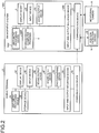
- FIG. 2 is a block diagram illustrating a hardware configuration of the mobile terminal 9 and the management system 1000, according to this embodiment.
- the mobile terminal 9 has an arithmetic processing device 9A, a storage device 9B, a display device 9C, an input device 9D, a sound output device 9E, a sound input device 9F, a photographing device 9G, an input and output interface device 9H, and a communication device 9K.
- the arithmetic processing device 9A includes a microprocessor, such as a central processing unit (CPU).
- the storage device 9B includes a memory, such as a read only memory (ROM) or a random access memory (RAM), and a storage.
- ROM read only memory
- RAM random access memory
- the display device 9C includes a flat panel display, such as a liquid crystal display (LCD), or an organic electroluminescence display (OLED). By being operated, the input device 9D generates input data.
- the input device 9D includes a touch sensor provided on a display screen of the display device 9C.
- the display device 9C includes a touch panel.
- the sound output device 9E includes a speaker.
- the sound input device 9F includes a microphone.
- the photographing device 9G has a video camera function enabling moving image data of a subject to be obtained, and a still camera function enabling still image data of a subject to be obtained.
- the photographing device 9G has an optical system, and an imaging element that obtains photographic data of a subject via the optical system.
- the imaging element includes a charge coupled device (CCD) image sensor or a complementary metal oxide semiconductor (CMOS) image sensor.
- the input and output interface device 9H carries out data communication with the arithmetic processing device 9A, the storage device 9B, the display device 9C, the input device 9D, the sound output device 9E, the sound input device 9F, the photographing device 9G, and the communication device 9K.
- the communication device 9K carries out data communication wirelessly with the management system 1000.
- the communication device 9K carries out data communication with the management system 1000 by using at least one of a mobile phone communication network, the Internet connection, and a local area network.
- the management system 1000 includes the computer system 4.
- the management system 1000 has an arithmetic processing device 1002, a storage device 1004, the display device 5, an input device 20, a sound output device 5S, an input and output interface device 1006, and a communication device 21.
- the arithmetic processing device 1002 includes a microprocessor, such as a CPU.
- the storage device 1004 includes a memory, such as a ROM or a RAM, and a storage.
- the arithmetic processing device 1002 executes arithmetic processing according to a computer program stored in the storage device 1004.
- the display device 5 includes a flat panel display. By being operated, the input device 20 generates input data.
- the input device 20 includes at least one of a keyboard and a mouse.
- the input device 20 may include a touch sensor provided on a display screen of the display device 5.
- the sound output device 5S includes a speaker.
- the input and output interface device 1006 carries out data communication with the arithmetic processing device 1002, the storage device 1004, the display device 5, the input device 20, the sound output device 5S, and the communication device 21.
- the communication device 21 carries out data communication wirelessly with the mobile terminal 9.
- the communication device 21 carries out data communication with the mobile terminal 9 by using at least one of a mobile phone communication network, the Internet connection, and a local area network.
- the mobile terminal 9 and the management system 1000 may carry out data communication wiredly. Further, the management system 1000 is able to carry out data communication with position detection devices 22 provided in the portable devices 6, and monitoring cameras 23 provided in the plant 1.
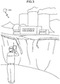
- FIG. 3 is a diagram illustrating an example of the mobile terminal 9 according to this embodiment.
- an operator is able to obtain images or videos (moving images) of various positions (places) in the plant 1, by using a camera of the mobile terminal 9. Further, the operator is able to obtain sound in various places of the plant 1, by using the sound input device 9F of the mobile terminal 9.
- the operator is able to obtain an image of a traveling path (road) provided on the premises of the plant 1, by using the photographing device 9G.
- the operator is able to obtain an image of inside of the construction 2, by using the photographing device 9G.
- An image of the plant 1 obtained by the photographing device 9G of the mobile terminal 9 is transmitted wirelessly to the management system 1000.
- FIG. 4 is a diagram illustrating an example of the mobile terminal 9 according to this embodiment.
- the device vehicle 8 vehicle 7
- the operator is able to drive the device vehicle 8 while looking at the display device 9C of the mobile terminal 9.
- Data transmitted from the management system 1000 to the mobile terminal 9 are displayed on the display device 9C of the mobile terminal 9.
- the operator is able to drive while looking at the data displayed on the display device 9C of the mobile terminal 9.
- the operator is able to drive by using a navigation function of the mobile terminal 9.
- the navigation function of the mobile terminal 9 includes navigation with sound and navigation with images.
- FIG. 5 is a diagram illustrating an example of the display device 5 of the management system 1000 according to this embodiment.
- the display device 5 includes a touch panel.
- An operator is able to operate a screen displayed on the display device 5 by touching the touch sensor provided on the display screen of the display device 5.
- the operator is able to input an input signal (operation signal) by touching the touch sensor of the display device 5.
- the display device 5 includes a combination of plural touch panels.
- two wide type touch panels are vertically arranged, and three wide type touch panels are horizontally arranged. That is, in this embodiment, the display device 5 includes a combination of six touch panels.
- the display device 5 includes six displays and one large sized touch sensor set extending over the six displays.
- the display device 5 is able to display a main screen 5A and subscreens 5B.
- a main screen area where the main screen 5A is displayed plural main screens 5A are able to be displayed.
- the subscreens 5B are arranged below the main screen 5A.
- the main screen 5A is able to display thereon display data input to the display device 5 by use of at least one of an image, a numerical value, and a character.
- display data depicting a cooling system and a power source system of the plant 1 are displayed on the main screen 5A.
- the subscreens 5B are plurally provided.
- Each of the subscreens 5B is able to display thereon display data input to the display device 5 by use of at least one of an image, a numerical value, and a character.
- display data being displayed on the main screen 5A and display data on the specific subscreen 5B are switched over to each other.
- the display data on the touched specific subscreen 5B are displayed on the main screen 5A.
- arbitrary main screen 5A and subscreen 5B that have been selected may be switched over to each other.
- the display device 5 is able to highlight a specific subscreen 5B of the plural subscreens 5B. For example, priority (importance) of display data is set in three levels.
- a subscreen 5B (5Bb) displaying thereon first priority display data with the highest priority is highlighted by a pop-up or display having motion.
- a subscreen 5B (5Ba) displaying thereon second priority display data having the second highest priority next to the first priority display data is highlighted by a colored frame being displayed therearound.
- the subscreen 5B (5Ba) may be highlighted by a blinking frame being displayed therearound.
- Subscreens 5B displaying thereon third priority display data having the lowest priority are not highlighted.
- the display device 5 has the sound output device 5S that outputs sound data.
- the sound output device 5S includes a speaker.
- the display device 5 is able to generate sound by using the sound output device 5S.
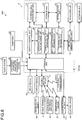
- FIG. 6 is a functional block diagram illustrating an example of the management system 1000 according to this embodiment.
- the management system 1000 includes the computer system 4, and the display device 5.
- the management system 1000 includes a power source planning system 10 that plans restoration or use of power sources 50 in the plant 1.
- the power source planning system 10 functions as a condition determination system that determines, based on operation condition data of the power sources 50, a level of a phenomenon that occurs in the plant 1.
- the management system 1000 includes a decision-making support system 100 that supports decision-making for measures against various phenomena at the time of emergency (abnormality), like when a disaster occurs. Functions of the power source planning system 10 are demonstrated by the arithmetic processing device 1002 of the computer system 4, and the computer program stored in the storage device 1004.
- the power sources 50 include the existing power source 3B, and the portable power source 6B that substitutes for the existing power source 3B.
- the power sources 50 are plurally arranged in the plant 1.
- the power source planning system 10 obtains operation condition data indicating an operation condition of each of the plural power sources 50.
- the power source planning system 10 obtains the operation condition data of the power sources 50, and determines whether or not any abnormality has occurred in the power sources 50. If an abnormality occurs in some of the power sources 50 by occurrence of a disaster, the power source planning system 10 plans various requirements related to the power sources 50, including a recovery plan for the power sources 50 and a use plan for the operable power sources 50.
- the existing power source 3B includes the external power source, the internal power source, the emergency power source, and the storage battery power source.
- the emergency power source includes an emergency generator (diesel generator: DG) that is able to generate electricity by use of a diesel engine.
- DG diesel generator
- the display device 5 displays thereon plural power sources 50 that are able to supply power to electric devices 30 of the plant 1 operated by power.
- the display device 5 displays thereon normal power sources 50 and abnormal power sources 50 in different designs. Thereby, via the display device 5, states of the power sources 50 are recognized promptly. Therefore, planning for the power sources 50 is carried out appropriately.
- the computer system 4 of the management system 1000 has an interface unit 11, a data obtaining unit 80, an information management unit 12, a power source management unit 13, a storage unit 15, a determination unit 16, a simulation unit 17, and a display control unit 18.
- Functions of the interface unit 11 are demonstrated by the input and output interface device 1006.
- Functions of the storage unit 15 are demonstrated by the storage device 1004.
- Functions of the data obtaining unit 80, the information management unit 12, the power source management unit 13, the determination unit 16, the simulation unit 17, and the display control unit 18 are demonstrated by the arithmetic processing device 1002.
- the management system 1000 includes: a database unit 19 connected to the computer system 4; the input device 20 connected to the computer system 4; the display device 5 connected to the computer system 4; the mobile terminals 9; the position detection devices 22; the monitoring cameras 23; and the communication device 21 that is able to communicate with the power sources 50.
- the communication device 21 may be a wireless communication device, or a wired communication device.
- the input device 20 includes at least one of a keyboard, a mouse, a microphone, and a camera, and generates an input signal (operation signal) by being operated by an operator. Plural input devices 20 may be included. If the display device 5 includes a touch panel, the input device 20 includes a display unit of the display device 5. The input signal generated by the operation on the input device 20 is supplied to the interface unit 11.
- the position detection devices 22 detect positions of the portable devices 6 (device vehicles 8) and output position data indicating the positions of the portable devices 6.
- the position detection devices 22 include a global positioning system (GPS). GPS devices (GPS receivers) are installed in the device vehicles 8.
- GPS devices GPS receivers
- the position detection devices 22 include the GPS devices installed in the device vehicles 8.
- Positions of the portable devices 6 (device vehicles 8) in a global coordinate system are detected by the position detection devices 22.
- the position data indicating the positions of the portable devices 6 detected by the position detection devices 22 are supplied to the interface unit 11 via the communication device 21.
- the position data detected by the position detection devices 22 may be temporarily stored, and supplied to the interface unit 11 wiredly connected thereto.
- the monitoring cameras 23 are installed at plural positions in the plant 1. Image data obtained by the monitoring cameras 23 are supplied to the interface unit 11 via the communication device 21.
- the mobile terminals 9 and the computer system 4 may be wirelessly connected to each other, or wiredly connected to each other. Data communication may be executed in a state where the mobile terminal 9 and the computer system 4 have been wiredly connected to each other.
- the position detection devices 22 and the computer system 4 may be wirelessly connected to each other, or wiredly connected to each other. Data communication may be executed in a state where the position detection device 22 and the computer system 4 have been wiredly connected to each other.
- the monitoring cameras 23 and the computer system 4 may be wiredly connected to each other.
- the interface unit 11 obtains data supplied from external devices of the computer system 4. Further, the interface unit 11 supplies data from the computer system 4 to the external devices.
- the data obtaining unit 80 has: an operation condition data obtaining unit 81 that obtains operation condition data indicating operation conditions of the power sources 50; a characteristic data obtaining unit 82 that obtains characteristic data of each of the plural power sources 50; a necessary power data obtaining unit 83 that obtains necessary power data indicating power necessary for the electric devices 30 to operate; and a position data obtaining unit 84 that obtains position data indicating a position of the portable power source 6B.
- the operation condition data obtaining unit 81 obtains the operation condition data indicating an operation condition of each of the plural power sources 50.
- the operation condition data are supplied to the operation condition data obtaining unit 81 from the power source 50 (existing power source 3B or portable power source 6B) via the interface unit 11.
- a signal indicating a normal state (normal signal) is supplied from the power source 50 to the operation condition data obtaining unit 81.
- a signal indicating an abnormal state is supplied from the power source 50 to the operation condition data obtaining unit 81.
- the operation condition data include at least one of the normal signal and the abnormal signal.
- the normal state of the power source 50 includes a state where the power source 50 operates normally and is able to output expected power.
- the abnormal state of the power source 50 includes an inoperable state, and a state where the power source 50 does operate but is unable to output expected power.
- the characteristic data obtaining unit 82 obtains the characteristic data of each of the plural power sources 50.
- the characteristic data of the power sources 50 include power feeding capabilities of the power sources 50.
- the characteristic data of the power sources 50 are stored in the storage unit 15.
- the characteristic data obtaining unit 82 obtains the characteristic data of each of the plural power sources 50 from the storage unit 15.
- the necessary power data obtaining unit 83 obtains the necessary power data indicating the power necessary for the electric devices 30 to operate.
- the necessary power data of the electric devices 30 are stored in the storage unit 15.
- the interface unit 11 obtains necessary power data of each of the plural electric devices 30 from the storage unit 15.
- the position data obtaining unit 84 obtains position data indicating positions of the portable devices 6 including the portable power source 6B.
- the position data indicating the positions of the portable devices 6 detected by the position detection devices 22 are supplied to the position data obtaining unit 84 via the communication device 21.
- the existing power source 3B includes the storage battery power source.
- the portable power source 6B includes a storage battery power source.
- the operation condition data obtaining unit 81 is able to obtain remaining capacity data indicating remaining battery capacities of the storage battery power sources. Remaining capacity data are supplied from the existing power source 3B including the storage battery power source, to the operation condition data obtaining unit 81. Remaining capacity data are supplied from the portable power source 6B including the storage battery power source, to the operation condition data obtaining unit 81.
- the operation condition data of the power sources 50 include the remaining capacity data of the storage battery power sources.
- the operation condition data obtaining unit 81 is able to obtain power feedable time data indicating time periods, over which the storage battery power sources are able to feed power.
- Power feedable time data are supplied from the existing power source 3B including the storage battery power source, to the operation condition data obtaining unit 81.
- Power feedable time data are supplied from the portable power source 6B including the storage battery power source, to the operation condition data obtaining unit 81.
- the operation condition data of the power sources 50 include the power feedable time data of the storage battery power sources.
- the operation condition data obtaining unit 81 functions as a remaining capacity data obtaining unit that obtains the remaining capacity data indicating the remaining battery capacities of the storage battery power sources.
- the operation condition data obtaining unit 81 functions as a power feedable time data obtaining unit that obtains the power feedable time data indicating the time periods, over which the storage battery power sources are able to feed power.
- a time period, over which a storage battery power source is able to feed power, is calculated based on necessary power of a device or devices that the power is fed to.
- the power source management unit 13 manages, based on the respective operation condition data of the plural power sources 50 obtained by the operation condition data obtaining unit 81, a state (normal state or abnormal state) of each of the plural power sources 50.
- the power source management unit 13 generates, based on the respective operation condition data of the plural power sources 50 obtained by the operation condition data obtaining unit 81, data to be displayed on the display device 5.
- the storage unit 15 stores therein data necessary for planning for the power sources 50.
- the storage unit 15 stores therein the characteristic data of each of the plural power sources 50.
- the storage unit 15 stores therein the necessary power data of each of the plural electric devices 30.
- the power source management unit 13 elects, based on the necessary power data and characteristic data stored in the storage unit 15, the power source 50 to be assigned to a specific one of the electric devices 30.
- the display control unit 18 controls the display device 5.
- the display control unit 18 generates display data to be displayed on the display device 5, by processing data supplied from the data obtaining unit 80 and the power source management unit 13.
- the interface unit 11 is connected to a plant system 31 via an emergency operating parameter transmission system 32. Further, the interface unit 11 is connected to a subsystem 33.
- the plant system 31 manages plant data of the plant 1.
- the plant data include operation data for the nuclear reactor system, and are detected by sensors arranged in the nuclear reactor system.
- the plant data include, for example, temperature data of the nuclear reactor, and flow rate data of the primary cooling water of the nuclear reactor system.
- the data obtaining unit 80 is able to obtain the plant data from the plant system 31.
- the emergency operating parameter transmission system 32 outputs emergency operating parameters of the plant 1.
- the data obtaining unit 80 is able to obtain the emergency operating parameters from the emergency operating parameter transmission system 32.
- the subsystem 33 manages peripheral data of the plant 1, the peripheral data being different from the plant data.
- the peripheral data include, for example, meteorological data.
- the data obtaining unit 80 is able to obtain the peripheral data from the subsystem 33.
- the information management unit 12 manages the plant data supplied from the plant system 31. Further, the information management unit 12 manages data supplied from the subsystem 33, the input device 20, and the communication device 21. Furthermore, the information management unit 12 manages data stored in the database unit 19. The display control unit 18 generates display data to be displayed on the display device 5, from the data managed by the information management unit 12.
- the simulation unit 17 estimates change over time of the plant 1 based on the plant data, and generates scenario data (plant presumption data) indicating a presumed phenomenon in the plant 1.
- the database unit 19 stores therein the operation condition data, the characteristic data, the necessary power data, the position data, and the remaining capacity data, which have been obtained by the data obtaining unit 80.
- the database unit 19 stores therein the plant data supplied from the plant system 31, the scenario data generated by the simulation unit 17, and the display data generated by the display control unit 18. Further, the database unit 19 stores therein data from the subsystem 33, the input device 20, and the communication device 21.
- FIG. 7 is a diagram illustrating an example of the display device 5 according to this embodiment.
- FIG. 7 is an example of display when the plant 1 is normal.
- the plant 1 being normal includes a state where no disaster has occurred and the power sources 50 are normal.
- the existing power source 3B includes an external power source 3Bd, an internal power source 3Bc, an emergency power source 3Bb that is able to generate electricity with a diesel engine, and a storage battery power source 3Ba.
- images depicting the power sources 50 are displayed on the display device 5. Further, an image representing a power source line 55 that is connectable to the power sources 50, and a transformer 56 are displayed on the display device 5.
- power is supplied to the power source line 55 from outside (an external power source) of the plant 1.
- the power supplied from the outside is used.
- Power may be supplied to the power source line 55 from the external power source 3Bd or the internal power source 3Bc, of the existing power source 3B.
- the power supplied from the external power source 3Bd or the internal power source 3Bc may be used by the electric devices 30.
- the portable power source 6B When the plant 1 is normal, the portable power source 6B is not connected to the power source line 55.
- the emergency power source 3Bb does not operate.
- the plant 1 When the plant 1 is normal, power is not supplied from the storage battery power source 3Ba to the power source line 55. Even when the plant 1 is normal, as necessary, power may be supplied from the storage battery power source 3Ba. Further, if a trouble of some sort, even though not a severe accident, occurs, the emergency power source 3Bb may operate.
- operation condition data including normal signals are supplied from the power sources 50 (existing power source 3B and portable power source 6B) to the data obtaining unit 80.
- the display control unit 18 generates, based on the operation condition data including the normal signals, data to be displayed on the display device 5.
- the display device 5 displays thereon an electric system of the plant 1, the electric system including the power sources 50 and the power source line 55. Thereby, an operator (administrator) is able to promptly and appropriately recognize a state of the electric system via the display device 5.
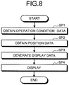
- Step SP1 If a disaster, such as a severe accident, occurs in the plant 1, and power supply from outside (an external power source) of the plant 1 is stopped due to the occurrence of the disaster, operation condition data indicating an operation condition of each of the plural power sources 50 of the plant 1 are obtained (Step SP1).
- the power sources 50 include a storage battery power source
- the operation condition data include remaining capacity data indicating a remaining battery capacity of a storage battery thereof.
- the display control unit 18 generates, based on the obtained operation condition data and position data, display data to be displayed on the display device 5 (Step SP3).
- the display device 5 displays thereon the electric system of the plant 1 at the time of the occurrence of the disaster (at the time of emergency) (Step SP4).
- FIG. 9 is a diagram illustrating an example of the display device 5 according to this embodiment.
- FIG. 9 is an example of display when the plant 1 is abnormal.
- the plant 1 being abnormal includes a state where a disaster has occurred and the power sources 50 are abnormal.
- images depicting the power sources 50 are displayed on the display device 5. Further, an image depicting the power source line 55 connectable to the power sources 50, and the transformer 56 are displayed on the display device 5.
- the display control unit 18 causes the display device 5 to display thereon normal power sources 50 and abnormal power sources 50 in different designs.
- the determination unit 16 classifies, based on the operation condition data of each of the plural power sources 50 obtained by the operation condition data obtaining unit 81, the plural power sources 50 into the normal power sources 50 and the abnormal power sources 50. Based on results of the determination by the determination unit 16, the display control unit 18 generates first display data representing the normal power sources 50 and second display data representing the abnormal power sources, and causes the display device 5 to display thereon the first display data and the second display data.
- one emergency power source 3Bb1 of two emergency power sources 3Bb is abnormal, and the other emergency power source 3Bb2 is normal.
- the display device 5 displays an icon representing the emergency power source 3Bb1 and an icon representing the emergency power source 3Bb2, in different designs.
- the icon representing the emergency power source 3Bb1 is colored in a first color
- the icon representing the emergency power source 3Bb2 is colored in a second color different from the first color.
- an icon representing one of the emergency power sources 3Bb and an icon representing the other emergency power source 3Bb are displayed in designs that are substantially the same.
- the display device 5 displays thereon remaining capacity data indicating a remaining battery capacity of the storage battery power source 3Ba.
- the remaining capacity data are displayed by use of a bar (bar graph) 57.
- text indicating that the storage battery power source 3Ba is being charged is displayed on the display device 5.
- the display device 5 displays thereon remaining capacity data indicating a remaining battery capacity of the portable power source 6B including the storage battery power source.
- the remaining capacity data are displayed by use of a bar (bar graph) 58.
- the display device 5 displays thereon the position data indicating the position of the portable power source 6B (device vehicle 8). In this embodiment, by adjusting a position of an icon representing the portable power source 6B, the display device 5 displays thereon the position data indicating the position of the portable power source 6B.
- FIG. 9 an example, in which the portable power source 6B has been connected to the power source line 55, is illustrated.
- power supply from the outside is stopped, and supply of power from the internal power source 3Bc is also stopped, power from at least one of the emergency power sources 3Bb, the storage battery power source 3Ba, and the portable power source 6B, is supplied to the power source line 55.
- the power output from at least one of the emergency power sources 3Bb, the storage battery power source 3Ba, and the portable power source 6B is supplied to the electric devices 30 via the power source line 55.
- the power source management unit 13 elects the power source 50 to be assigned to a specific electric device 30 of the plural electric devices 30 arranged in the plant 1, based on the necessary power data indicating the power necessary for the electric devices 30 to operate and the characteristic data indicating the power feeding capability of each of the plural power sources 50 (the emergency power sources 3Bb, the storage battery power source 3Ba, and the portable power source 6B).
- the power (electric current) necessary for the electric device 30 to operate is at a power value, "a”.
- the power feeding capability of the emergency power source 3Bb is at a power value, "b”, smaller than the power value, "a" even if the emergency power source 3Bb and the electric device 30 are connected to each other and power is supplied from the emergency power source 3Bb to the electric device 30 via the power source line 55, the electric device 30 is unable to be operated.
- the power feeding capability of the storage battery power source 3Ba is at a power value, "c”, smaller than the power value, "a”
- the electric device 30 is also unable to be operated by use of power output from the storage battery power source 3Ba. If the power feeding capability of the portable power source 6B is at a power value, "A”, larger than the power value, "a”, the electric device 30 is able to be operated by use of power output from the portable power source 6B.
- the necessary power data indicating the power necessary for the electric devices 30 to operate and the characteristic data indicating the power feeding capability of each of the emergency power sources 3Bb, the storage battery power source 3Ba, and the portable power source 6B are stored in the storage unit 15.
- the power source management unit 13 is able to elect, based on the necessary power data and characteristic data, the power source 50 (in this example, the portable power source 6B) to be assigned to the electric device 30.
- the display device 5 By the display device 5 displaying the elected power source 50 (in this example, the portable power source 6B), an operator (administrator) is able to determine, based on the displayed result on the display device 5, a plan for connection of the portable power source 6B to the power source line 55.
- the elected power source 50 in this example, the portable power source 6B
- an operator is able to determine, based on the displayed result on the display device 5, a plan for connection of the portable power source 6B to the power source line 55.
- the display device 5 may display thereon the plural power sources 50 (emergency power sources 3Bb, storage battery power source 3Ba, and portable power source 6B) respectively in association with capabilities (power feeding capabilities) of the power sources 50.
- the plural power sources 50 emergency power sources 3Bb, storage battery power source 3Ba, and portable power source 6B
- the display device 5 may display thereon power feedable time data indicating a time period, over which the storage battery power source 3Ba is able to feed power.
- the operation condition data indicating the operation condition of each of the plural power sources 50 are obtained, and the normal power sources 50 and the abnormal power sources 50 are displayed in different designs, an administrator is able to promptly recognize states of the power sources 50 via the display on the display device 5.
- planning for the power sources 50 such as making a recovery plan for the power sources 50 or a use plan for the operable power sources 50, is able to be carried out appropriately.
- the power sources 50 include a storage battery power source
- remaining capacity data indicating a remaining battery capacity thereof are displayed on the display device 5.
- the power source 50 with a large remaining battery capacity is able to be assigned appropriately.
- the display control unit 18 causes the display device 5 to display thereon each of the plural power sources 50 in association with the capability of that power source 50. Thereby, which of the power sources 50 should be used to supply power is able to be determined promptly.
- the power source 50 to be assigned to the electric device 30 is elected and displayed on the display device 5.
- the display control unit 18 causes the display device 5 to display thereon the position data indicating the position of the portable power source 6B.
- the position of the portable power source 6B is able to be recognized promptly, and planning for the power sources 50 is able to be carried out appropriately.
- any abnormal power source 50 or abnormal transformer 56 is highlighted in a different design.
- the display device 5 may identify and display a position in the power source line 55, the position being where that abnormality has occurred. For example, in a display area indicating a portion where disconnection has occurred, a mark, "x", may be displayed.
- Plant data including operation condition data of these facilities are obtained by the operation condition data obtaining unit 81.
- the determination unit 16 determines, based on the plant data including the operation condition data of the facilities of the plant 1, a level of a phenomenon presumed to occur in the plant 1 due to operation conditions of the facilities.
- the level of the phenomenon includes a level of damage caused when that phenomenon occurs.
- the simulation unit 17 Based on the plant data, the simulation unit 17 generates scenario data (plant presumption data) indicating the presumed phenomenon of the plant 1. For example, based on the operation condition data on the power sources 50, the simulation unit 17 is able to generate the scenario data of the plant 1.
- scenario data plant presumption data
- the simulation unit 17 is able to generate the scenario data of the plant 1.
- the determination unit 16 determines the level of the presumed phenomenon in the plant 1.
- relation data indicating relations between the operation conditions of the facilities, and phenomena in the plant 1 and levels of the phenomena are stored in the storage unit 15, the phenomena being presumed to occur due to the operation conditions of the facilities.
- relation data indicating relations between operation conditions of the plural power sources 50 and levels of function loss of the electric devices 30 presumed from the operation conditions of these power sources 50 are stored in the storage unit 15.
- a level of function loss of the electric devices 30 refers to the number of electric devices 30 that lose their functions.
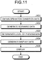
- FIG. 11 is a flow chart illustrating an example of a condition determination method for the plant 1 according to this embodiment.
- the operation condition data obtaining unit 81 obtains operation condition data of each of the plural power sources 50 provided in the plant 1 (Step SQ1).
- the simulation unit 17 Based on the operation condition data of each of the plural power sources 50 obtained by the operation condition data obtaining unit 81 and the relation data stored in the storage unit 15, the simulation unit 17 generates scenario data of the plant 1 (Step SQ2).
- the determination unit 16 determines a level of a phenomenon in the plant 1, the phenomenon being presumed to occur due to those operation conditions of the power sources 50 (Step SQ3). In this embodiment, the determination unit 16 determines, as the level of the phenomenon in the plant 1, the number of electric devices 30 that lose their functions.
- the display control unit 18 generates display data based on a result of the determination by the determination unit 16 (Step SQ4).
- the display data include the number and positions of the electric devices 30 that lose their functions.
- the display control unit 18 causes the display device 5 to display thereon the generated display data (Step SQ5).
- the level (damage level) of the phenomenon presumed to occur due to the operation conditions of the facilities is able to be determined. Thereby, determination of the conditions is able to be carried out promptly.
- the determination unit 16 is able to determine the level of the phenomenon, based on the operation condition data on the facilities obtained by the operation condition data obtaining unit 81 and the relation data stored in the storage unit 15. Therefore, determination of the conditions is able to be carried out promptly.
- the display data are generated and displayed on the display device 5. Thereby, an administrator is able to visually recognize the determination result for the level of the phenomenon.
- a condition determination system 10 In a condition determination system 10 according to this embodiment, items related to the plant 1 are stored in the storage unit 15 or the database unit 19, the items having been classified into condition levels for respective phenomena corresponding to the items.
- the determination unit 16 determines whether a condition level has been reached by receiving check results for items of a phenomenon.
- the items related to the plant 1 include items of operation conditions of facilities in the plant 1.
- the check results for the items of the phenomenon include operation condition data of the facilities obtained by the operation condition data obtaining unit 81.
- the operation condition data (check results for the items of the phenomenon) include input signals supplied from the sensors provided in the plant 1.
- the condition level includes a level of the phenomenon, and includes a level of damage caused when that phenomenon occurs. That is, in this embodiment, in the storage unit 15 or the database unit 19, relation data indicating relations between operation conditions of the facilities and condition levels for the respective phenomena are stored. Based on the operation condition data obtained by the operation condition data obtaining unit 81 (check results for the items of the phenomenon) and the relation data stored in the storage unit 15 or the database unit 19, the determination unit 16 determines whether the phenomenon has reached a prescribed condition level.
- Items of operation conditions of the facilities in the plant 1, that is, the items related to the plant 1, are determined beforehand for determination of a condition level of the plant 1. Examples thereof will be illustrated in FIG. 12 to FIG. 14 .
- the items of the operation conditions include "level number”, “phenomenon”, “phenomenon details”, “check item and satisfying requirement thereof", and "input signal and satisfying value thereof".
- Phenomenon is a phenomenon expected in the plant 1.
- Phenomenon details are detailed contents of the phenomenon.
- condition levels are classified into three levels, low, intermediate, and high levels.
- high condition level damage to the plant 1 is large.
- low condition level damage to the plant 1 is comparatively small.
- Level number indicates a number of a phenomenon that has been numbered.
- Check item is an item to be checked in the plant 1.
- "Satisfying requirement” indicates a requirement, under which "phenomenon” is determined likely to occur. When items checked according to the check items are satisfied, it is determined that "phenomenon” has occurred.
- “Input signal” is a signal including operation condition data and supplied from a sensor provided in the plant 1.
- "Satisfying value” indicates a signal value, at which "phenomenon” is determined likely to occur. When the values of the input signals are satisfied, it is determined that "phenomenon” has occurred.
- FIG. 12 illustrates an example, in which the condition level is low, and "number” is “10".
- a phenomenon of the condition level of "number 10" is "risk of function loss of facility A”.
- Detailed contents of this phenomenon of the condition level of "number 10" are that when a pump A is being used in any of operation modes 1, 2, 3, and 4 for a specific use, in a state where water supply from the pump A has been lost, (1) starting of only one of a pump B and a pump C is able to be confirmed, and (2) a total of water supply flow rates to the pump A is less than a specific value (X m 3 /h).
- the state signal value of each of the operation modes is "1" when the current operation mode is that mode, and is "0" when the current operation mode is not that mode. What kind of states of the facilities and devices the values of the state signal values indicate are prescribed for the respective signals.
- the state signal value of a pump D 0.
- the state signal value of the pump D is "1" in an activated state of the pump, and is "0" in a stopped state of the pump.
- the state signal value of a pump E 0.
- the state signal value of the pump E is "1" in an activated state of the pump, and is "0" in a stopped state of the pump.
- the state signal value of a pump F 0.
- the state signal value of the pump F is "1" in an activated state of the pump, and is "0" in a stopped state of the pump.
- the state signal value of a pump G 0.
- the state signal value of the pump G is "1" in an activated state of the pump, and is "0" in a stopped state of the pump.
- the state signal value of the pump B1 0.
- the state signal value of the pump B1 is "1" in an activated state of the pump, and is "0" in a stopped state of the pump.
- the state signal value of the pump B2 0.
- the state signal value of the pump B2 is "1" in an activated state of the pump, and is "0" in a stopped state of the pump.
- the state signal value of a valve A 1.
- the state signal value of the valve A is "0" in an open state of the valve, and is "1" in a closed state of the valve.
- a state signal value of a valve B 1.
- the state signal value of the valve B is "0" in an open state of the valve, and is "1" in a closed state of the valve.
- the state signal value of a valve C 1.
- the state signal value of the valve C is "0" in an open state of the valve, and is "1" in a closed state of the valve.
- the state signal value of a valve D 1.
- the state signal value of the valve D is "0" in an open state of the valve, and is "1" in a closed state of the valve.
- Each of the signal values of the flow rates B, C, and D is a numerical value of individual continuous quantity.
- Operation condition data include an input signal corresponding to a check item.
- An input signal that is operation condition data of a facility is obtained by the operation condition data obtaining unit 81.
- the determination unit 16 determines whether or not the input signal obtained by the operation condition data obtaining unit 81 satisfies a satisfying value thereof. If it is determined that the input signal satisfies the satisfying value, a satisfying signal is generated. As illustrated in FIG. 12 , a satisfying signal for each satisfied input signal is input to determination logic. When a logic diagram is satisfied up to a right end thereof, the determination unit 16 determines that the phenomenon, "risk of function loss of facility A", of the low level number 10 has occurred.
- the determination unit 16 is able to automatically determine whether or not the phenomenon occurs, based on whether or not the input signals satisfy the satisfying values, and the determination logic.
- a quadrilateral mark corresponds to a case where all have been satisfied
- a circular mark corresponds to a case where any one of them has been satisfied.
- FIG. 13 illustrates an example, in which the condition level is low, and "number” is "31".
- a phenomenon of the condition level of "number 31" is "risk of function loss of facility B".
- Detailed contents of this phenomenon of the condition level of "number 31" are that leakage or transpiration of stored water in a facility B has been confirmed, level of stored water in a pit of the facility B (1) level of the stored water in the facility B decreased to be equal to or less than a specific position, and (2) in a state where a low stored water level warning has been transmitted or where there is a risk thereof; a state, in which level of the stored water used is unable to be confirmed with a measuring instrument or visually, has continued for a specific time period or longer.
- the stored water leakage detection warning signal value 1.
- the value is "1" and when there is no stored water leakage detection warning, the value is "0".
- the value is "1"
- the level of the stored water is above the predetermined range, the value is "0".
- the low stored water level warning signal value for the a-pit 1. When there is a low stored water level warning for the a-pit, the value is "1", and when there is no low stored water level warning for the a-pit, the value is "0".
- the low stored water level warning signal value for the b-pit 1. When there is a low stored water level warning for the b-pit, the value is "1", and when there is no low stored water level warning for the b-pit, the value is "0".
- An input signal that is operation condition data of a facility is obtained by the operation condition data obtaining unit 81.
- the determination unit 16 determines whether or not the input signal obtained by the operation condition data obtaining unit 81 satisfies the satisfying value. If it is determined that the input signal satisfies the satisfying value, a satisfying signal is generated. As illustrated in FIG. 13 , a satisfying signal for each satisfied input signal is input to determination logic. When a logic diagram is satisfied up to a right end thereof, the determination unit 16 determines that the phenomenon, "risk of function loss of facility B", of the low level number 31 has occurred. The input signals corresponding to this phenomenon illustrated in FIG.
- a quadrilateral mark corresponds to a case where all have been satisfied
- a circular mark corresponds to a case where any one of them has been satisfied.
- FIG. 14 illustrates an example, in which the condition level is high, and "number” is "56".
- a phenomenon of the condition level of "number 56" is "loss of all alternating current power sources”. Detailed contents of this phenomenon of the condition level of "number 56" are that when stoppage of all alternating current power sources of the plant has been confirmed.
- the function stoppage signal value for the a-emergency high voltage bus 1.
- the value is "1”
- the value is "0”.
- the function stoppage signal value for the b-emergency high voltage bus 1.
- the value is "1”
- the value is "0”.
- An input signal that is operation condition data of a facility is obtained by the operation condition data obtaining unit 81.
- the determination unit 16 determines whether or not the input signal obtained by the operation condition data obtaining unit 81 satisfies the satisfying value. If it is determined that the input signal satisfies the satisfying value, a satisfying signal is generated. As illustrated in FIG. 14 , a satisfying signal for each satisfied input signal is input to determination logic. When a predetermined period (for example, one hour) has elapsed and a logic diagram has been satisfied up to a right end thereof, the determination unit 16 determines that the phenomenon, "loss of all alternating current power sources", of the high level number 56, has occurred. The input signals corresponding to this phenomenon illustrated in FIG.
- a quadrilateral mark corresponds to a case where all of the determinations or lower determination logic have/has been satisfied.
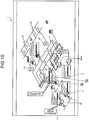
- the display control unit 18 After the determination unit 16 determines the condition level of the phenomenon, the display control unit 18 generates, based on the determination result by the determination unit 16, display data as illustrated in FIG. 15 , and causes the display device 5 to display thereon the display data.
- the information management unit 12 when a phenomenon has reached a condition level according to a determination result, the information management unit 12 generates report data based thereon.
- the report data are preferably generated in a standard format so as to be easily understood at a glance.
- the phenomenon number that has reached the condition level and a time thereof are included in the report data.
- the determination unit 16 executes the above described semi-automatic or manual determination, if there is no input by an operator, input into a frame of the corresponding phenomenon in FIG. 15 is preferably prompted by pop-up display on the display device 5.
- condition determination system 10 items related to the plant 1 are stored in the storage unit 15 or the database unit 19, the items having been classified into condition levels for respective phenomena corresponding to the items; the data obtaining unit 80 receives check results for the items of the phenomena; the determination unit 16 determines whether a predetermined condition level has been reached; and thereby, the condition determination system 10 is able to determine a condition level as long as the check results for the items of the phenomena that have been stored in the storage unit 15 or the database unit 19 are input. As a result, determination of a condition of the plant is able to be carried out promptly.
- the display control unit 18 generates, based on a determination result for a condition level of a phenomenon, display data, and causes the display device 5 to display thereon the display data.
- the condition determination system 10 enables a determination result for a condition level of each phenomenon to be visually recognized, through display data displayed on the display device 5.
- condition determination system 10 of this embodiment if check or determination for items requires human determination, the information management unit 12 prompts the check or determination.
- This condition determination system 10 enables delay in human determination to be reduced, and the effect of promptly executing determination of a condition of the plant to be assisted.
- the operation condition data of the facilities are obtained and the processing is executed.
- data indicating an abnormal situation such as "occurrence of an earthquake with an intensity of 6 or larger on the Japanese seven-stage seismic scale", “recognition of emergency”, or “occurrence of multiple accidents”, may be obtained, and processing may be executed.
- FIG. 16 is a diagram illustrating an example of a decision-making support system 100 according to this embodiment.
- the decision-making support system 100 supports decision-making for measures at the time of abnormality.
- plural decision-making support system 100A, decision-making support system 100B, decision-making support system 100C, decision-making support system 100D, and decision-making support system 100E are connected to one another to be able to communicate data via a network 70.
- a comprehensive nuclear reactor disaster network is constructed of the plural decision-making support systems (100A, 100B, 100C, 100D, and 100E) connected via the network 70.
- the network (comprehensive nuclear reactor disaster network) 70 is a comprehensive network utilized at the time of a disaster related to a nuclear reactor.
- Each of the plural decision-making support systems (100A, 100B, 100C, 100D, and 100E) has a configuration equivalent to that of the decision-making support system 100 described in the above embodiments.
- FIG. 16 illustrates an example, in which five decision-making support systems (100A, 100B, 100C, 100D, and 100E) are provided. Any number of decision-making support systems may be connected via the network 70.
- the decision-making support system 100A is arranged in, for example, a nuclear power plant.
- the decision-making support system 100B is arranged in, for example, a power company.
- the decision-making support system 100C is arranged in, for example, a relevant department of a municipality.
- the decision-making support system 100D is arranged in, for example, a relevant department of a nation.
- the nation includes at least one of a government policy organization, a regulation agency, and an off-site center.
- the decision-making support system 100E is arranged in, for example, a plant maker.
- decision-making support systems 100 when the plural decision-making support systems (100A, 100B, 100C, 100D, and 100E) do not need to be distinguished from one another, they will simply be referred to as the decision-making support systems 100.
- each of the plural decision-making support systems 100 has a synchronization management unit 60.
- the synchronization management unit 60 is connected to each of the interface unit 11 and the information management unit 12.
- the synchronization management unit 60 is connected to the network 70.
- the synchronization management unit 60 of one decision-making support system 100 of the plural decision-making support systems 100 shares data with the synchronization management units 60 of the other decision-making support systems 100.
- the synchronization management unit 60 executes transmission and reception of data, and update of data, through the network 70.
- the synchronization management unit 60 of one of the decision-making support systems 100 executes update of data, based on data received from the synchronization management unit 60 of another one of the decision-making support systems 100, when the one of the decision-making support systems 100 is reconnected to the network 70 after a predetermined time period has elapsed from disconnection thereof from the network 70.
- the plural decision-making support systems 100 are able to share data with one another via the network 70.
- a database unit 190 connected to the network 70 is provided.
- the plural decision-making support systems 100 share data with the database unit 190 via the network 70.
- the information management unit 12 causes the display control unit 18 to generate display data, based on abnormality data that are necessary at the time of abnormality.
- the abnormality data include data necessary for decision-making.
- the information management unit 12 shares the abnormality data via the network 70. That is, the information management unit 12 of one decision-making support system 100 of the plural decision-making support systems 100 shares the abnormality data with the information management units 12 of the other decision-making support systems 100.
- the information management unit 12 executes transmission and reception of the abnormality data, and update of the abnormality data, through the network 70.
- the abnormality data include the following data.
- the information management unit 12 selects abnormality data necessary for decision-making, from plural sets of abnormality data, and causes the display control unit 18 to generate display data by use of the selected abnormality data.
- the information management unit 12 of one of the decision-making support systems 100 shares the display data with the other decision-making support systems 100 via the network 70.
- the plural decision-making support systems (100A, 100B, 100C, 100D, and 100E) are respectively arranged at different related places.
- the related places include the nuclear power plant, the power company, the municipality, the nation, and the plant maker.
- Abnormality data that are required for decision making by the respective decision-making support systems (100A, 100B, 100C, 100D, and 100E) are usually different from one another.
- the information management unit 12 of each of the plural decision-making support systems selects, based on predetermined priority of abnormality data, a set of abnormality data with high priority, from the plural sets of abnormality data, and causes the display control unit 18 to generate display data by use of the selected set of abnormality data.
- the selected set of abnormality data includes latest data.
- the latest data include realtime data.
- Abnormality data are input to the information management unit 12 in real time.
- the database unit 190 executes storage thereof by association with a time, at which the abnormality data were input.
- the information management unit 12 causes the display control unit 18 to generate display data by use of the latest data.
- the display device 5 displays thereon the display data generated by use of the latest data.
- the selected set of abnormality data includes abnormality data fulfilling a priority display standard.
- the abnormality data fulfilling the priority display standard include abnormality data with a high risk and abnormality data with high importance.
- the information management unit 12 causes the display control unit 18 to generate display data by use of the abnormality data fulfilling the priority display standard.
- the display device 5 displays thereon the display data generated by use of the abnormality data fulfilling the priority display standard.
- the abnormality data fulfilling the priority display standard include, for example, plant data that have changed with a change rate exceeding a reference value that is determined beforehand in the plant 1.
- the plant data include, for example, fuel temperature data indicating fuel temperature that has changed with a change rate exceeding a predetermined reference value, in-reactor temperature data indicating in-reactor temperature that has changed with a change rate exceeding a reference value, and in-reactor pressure data indicating in-reactor pressure that has changed with a change rate exceeding a reference value.
- the display device 5 displays thereon the display data generated based on the plant data including these fuel temperature data, in-reactor temperature data, and in-reactor pressure data.
- the abnormality data fulfilling the priority display standard include, for example, peripheral data (meteorological data and the like) that have changed with a change rate exceeding a predetermined reference value.
- the peripheral data include, for example, rainfall data indicating amount of rainfall that has changed with a change rate exceeding a predetermined reference value, wind speed data indicating wind speed that has changed with a change rate exceeding a reference value, and seismic intensity data indicating seismic intensity that has changed with a change rate exceeding a reference value.
- the display device 5 displays thereon display data generated based on the peripheral data including these rainfall data, wind speed data, and seismic intensity data.
- the abnormality data fulfilling the priority display standard may include data supplied from a predetermined organization (for example, the nation).
- the information management unit 12 may cause the display device 5 to highlight the display data based on priority (importance) thereof. As described already by reference to FIG. 5 , this highlighting includes, for example, pop-up display, by which the display data are displayed so as to pop up.
- the information management unit 12 may cause the display control unit 18 to generate display data that have been organized into items of measures, based on abnormality data necessary for decision-making.
- the display device 5 displays thereon the organized display data.
- the items of measures include the following items.
- the database unit 190 stores therein plural sets of abnormality data.
- the information management unit 12 selects a set of abnormality data necessary for decision on items of respective measures, from the plural sets of abnormality data stored in the database unit 190, and causes the display control unit 18 to generate display data by use of the selected set of abnormality data.
- the display device 5 displays thereon the display data.
- the selected set of abnormality data include presumption data generated by estimation calculation of change in abnormality data over time.
- the simulation unit 17 generates plant presumption data by executing estimation calculation of change in plant data collected by the information management unit 12 over time.
- the information management unit 12 causes the display control unit 18 to generate display data by use of the plant presumption data generated by the simulation unit 17.
- the display device 5 displays thereon the display data.
- the information management unit 12 obtains necessary plant data (abnormality data) from the plant system 31. Further, the information management unit 12 obtains necessary peripheral data (abnormality data) from the subsystem 33. Furthermore, the information management unit 12 obtains various types of abnormality data via the network 70.
- the information management unit 12 causes the display control unit 18 to generate display data.
- the information management unit 12 may cause the display control unit 18 to generate display data by processing information input from the input device 20.
- the display device 5 displays thereon the generated display data.
- the decision-making support system 100 includes the condition determination system 10 described in the above described embodiments.
- the abnormality data include plant data, such as the operation condition data of the power sources 50. Thereby, the related places are able to share the data related to the power sources 50 in the plant 1.
- the decision-making support system 100 includes the condition determination system 10, and the information management unit 12 that shares abnormality data necessary at the time of emergency (at the time of abnormality) via the network 70.
- the abnormality data include plant data, such as the operation condition data of the power sources 50.
- the information management unit 12 is configured to be able to share information with the related places via the network 70, generates report data based on the condition level of the phenomenon, and distributes the report data to the respective places via the network 70.
- the condition determination system 10 enables the respective places to be notified of the determination result for the condition level of the phenomenon promptly by notifying the respective places of the report data via the network 70, and the related places to deal with the condition level urgently.
- the decision-making support systems 100 are applied to a nuclear power plant.
- the decision-making support systems 100 may be applied to at least one of a thermal power plant, a chemical plant, and an environmental plant.
- the decision-making support systems 100 may be applied, not only to disasters in plants, but also to disasters caused in urban areas by natural phenomena, such as earthquakes, typhoons, and tsunamis. Further, the decision-making support systems 100 may be applied to disasters, such as airplane falls and missile attacks.
- the decision-making support systems 100 are used when an accident or a disaster actually occurs.
- the decision-making support systems 100 may be applied to a drill for preparation for an accident or a disaster, the drill being carried out in the plant 1.
- the decision-making support systems 100 may be applied to a drill for preparation for an accident or a disaster, the drill being carried out in the nation or a local public organization.
- emergency or abnormality is a concept including: abnormal operation of the plant 1; occurrence of an accident; occurrence of a disaster; and a drill supposing occurrence of an accident or a disaster.
- the decision-making support system 100 including the condition determination system 10 is applied to a plant facility.
- the condition determination system 10 may be applied to any of various application targets, including, not only plant facilities, but also, for example, transportation facilities, such as expressways or railways, building facilities, such as apartment facilities or commercial facilities; and the like.
- a transportation facility has plural traffic lights and a power supply source for operating the traffic lights.
- the traffic lights are operated by power supplied from a power line installed by a power company. Further, the traffic lights are equipped with power sources for emergency. At the time of a power failure when power supply from the power line has stopped, the traffic lights are operated by power supplied from the power sources.
- the plural traffic lights are respectively equipped with the power sources.
- the transportation facility has the plural power sources that supply power respectively to the plural traffic lights.
- the condition determination system 10 obtains operation condition data indicating an operation condition of each of the plural power sources, and causes the display device 5 to display thereon normal power sources that have not lost their functions and abnormal power sources that have lost their functions, in different designs.
- the determination unit 16 is able to determine a level (damage level) of a phenomenon that occurs in the transportation facility due to the operation conditions of the power sources.
- the operation condition data obtaining unit 81 obtains the operation condition data of each of the plural power sources provided in the transportation facility.
- the simulation unit 17 Based on the operation condition data of each of the plural power sources obtained by the operation condition data obtaining unit 81 and relation data stored in the storage unit 15, the simulation unit 17 generates scenario data of the transportation facility.
- the determination unit 16 determines a level of a phenomenon in the transportation facility presumed to occur due to the operation conditions of the power sources. In this embodiment, the determination unit 16 determines the number of traffic lights that lose their functions, as a phenomenon level of the transportation facility.
- the display control unit 18 Based on a result of the determination by the determination unit 16, the display control unit 18 generates display data.
- the display data include the number and positions of the traffic lights that lose their functions.
- the display control unit 18 causes the display device 5 to display thereon the generated display data.
- FIG. 17 illustrates an example of display on the display device 5 according to this embodiment.
- the transportation facility has plural traffic lights 1500.
- the traffic lights 1500 are operated by power supplied from a power line installed by a power company.
- the traffic lights 1500 are operated by power supplied from power sources 50E that the traffic lights 1500 are equipped with.
- the condition determination system 10 obtains operation condition data indicating an operation condition of each of the plural power sources 50E, and causes the display device 5 to display thereon normal power sources 50E that have not lost their functions and abnormal power sources 50E that have lost their functions, in different designs.
- Abnormality data fulfilling a priority display standard like those described in the fourth embodiment above include, for example, facility data that have changed with a change rate exceeding a reference value that is determined beforehand in the transportation facility or an oil and gas facility.
- the facility data include, for example, rainfall data indicating amount of rainfall that has changed with a change rate exceeding a predetermined reference value, wind speed data indicating wind speed that has changed with a change rate exceeding a reference value, river water level data indicating river water level that has changed with a change rate exceeding a reference value, and snowfall data indicating amount of snowfall that has changed with a change rate exceeding a reference value.
- temperature data indicating facility temperature that has changed with a change rate exceeding a reference value and pressure data indicating facility pressure that has changed with a change rate exceeding a reference value are included.
- the display device 5 displays thereon display data generated based on these data.
- the above described processing by the condition determination system 10 according to the embodiments above may be realized by a computer program to be executed by a computer.
- a computer program provided from a server or the like may be installed in the above described computer system 4, and the computer system 4 may execute the above described processing according to the computer program.
- the computer program may be recorded in a storage medium 2000, and the computer system 4 may be caused to read that computer program and implement the above described processing.
- the storage medium 2000 any of various types of media, such as: a storage medium that optically, electrically, or magnetically records therein information, like a CD-ROM, a flexible disk, or a magneto-optical disk; or a semiconductor memory that electrically records therein information, like a ROM or a flash memory, may be used.
Landscapes
- Engineering & Computer Science (AREA)
- Business, Economics & Management (AREA)
- Human Resources & Organizations (AREA)
- Physics & Mathematics (AREA)
- General Physics & Mathematics (AREA)
- Economics (AREA)
- Strategic Management (AREA)
- Entrepreneurship & Innovation (AREA)
- Theoretical Computer Science (AREA)
- Quality & Reliability (AREA)
- Tourism & Hospitality (AREA)
- Marketing (AREA)
- General Business, Economics & Management (AREA)
- General Engineering & Computer Science (AREA)
- Development Economics (AREA)
- Operations Research (AREA)
- Game Theory and Decision Science (AREA)
- Educational Administration (AREA)
- Automation & Control Theory (AREA)
- Power Engineering (AREA)
- Health & Medical Sciences (AREA)
- Human Computer Interaction (AREA)
- Manufacturing & Machinery (AREA)
- Evolutionary Computation (AREA)
- High Energy & Nuclear Physics (AREA)
- Plasma & Fusion (AREA)
- Software Systems (AREA)
- Mathematical Physics (AREA)
- Medical Informatics (AREA)
- Artificial Intelligence (AREA)
- Computational Linguistics (AREA)
- Data Mining & Analysis (AREA)
- Computing Systems (AREA)
- Public Health (AREA)
- Water Supply & Treatment (AREA)
- General Health & Medical Sciences (AREA)
- Primary Health Care (AREA)
- Testing And Monitoring For Control Systems (AREA)
- Management, Administration, Business Operations System, And Electronic Commerce (AREA)
- Monitoring And Testing Of Nuclear Reactors (AREA)
Abstract
Description
- The present invention relates to a condition determination system, a condition determination method, a decision-making support system, a computer program, and a storage medium.
- When a disaster, such as a severe accident in a nuclear power plant, occurs, disaster measures offices are set up in various related places, and measures are taken. When a disaster occurs, decision-making for measures may be supported by use of a decision-making support system. Examples of the decision-making support system are disclosed in
Patent Literature 1 toPatent Literature 3. Further, techniques for managing information at the time of a disaster are described inPatent Literature 4 toPatent Literature 6. -
- Patent Literature 1: Japanese Unexamined Patent Application Publication No.
2013-088829 A - Patent Literature 2: Japanese Unexamined Patent Application Publication No.
2014-078070 A - Patent Literature 3: International Publication Pamphlet No.
WO 2014/057835 A - Patent Literature 4: Japanese Unexamined Patent Application Publication No.
2006-292402 A - Patent Literature 5: Japanese Unexamined Patent Application Publication No.
2011-210205 A - Patent Literature 6: Japanese Unexamined Patent Application Publication No.
2003-177686 A - When a disaster occurs in a plant, the condition of the plant needs to be determined accurately for measures to be taken. For accurate determination of a condition of a plant, a large number of data on the plant need to be collected. However, collection of a large amount of data takes time. If the determination of the condition of the plant is delayed, measures are delayed. Therefore, a technique for enabling a condition of a plant to be promptly determined is demanded. Further, not only for a plant facility, but also for, for example, a transportation facility, such as an expressway or a railway, or a building facility, such as an apartment facility or a commercial facility; a technique for promptly determining a condition of that facility when a disaster occurs is demanded.
- An object of an aspect of the present invention is to provide a condition determination system, a condition determination method, a computer program, and a storage medium, which enable prompt determination of a condition. Further, an object of another aspect of the present invention is to provide a decision-making support system that is able to effectively support decision-making by using the condition determination system.
- According to a first aspect of the present invention, a condition determination system is provided and includes an operation condition data obtaining unit that obtains operation condition data indicating an operation condition of a facility, and a determination unit that determines, based on the operation condition data, a level of a phenomenon that occurs due to the operation condition of the facility.
- According to the first aspect of the present invention, by the obtainment of the operation condition data of the facility, based on the operation condition data, the level of the phenomenon that occurs due to the operation condition of the facility is able to be determined. Thereby, the condition is able to be determined promptly.
- In the first aspect of the present invention, the condition determination system may include a storage unit that stores therein relation data indicating a relation between the operation condition of the facility and the level of the phenomenon. The determination unit may determine the level of the phenomenon, based on the operation condition data and the relation data.
- Thereby, when the operation condition data obtaining unit obtains the operation condition data of the facility, based on the relation data stored in the storage unit, the level of the phenomenon is able to be determined. Therefore, the condition is able to be determined promptly.
- In the first aspect of the present invention, the condition determination system may include a display control unit that generates display data, based on a result of the determination by the determination unit, and causes a display unit to display thereon the display data.
- Thereby, the determination result for the level of the phenomenon is able to be recognized visually.
- In the first aspect of the present invention, the operation condition data obtaining unit may obtain the operation condition data of each of plural facilities, the determination unit may classify, based on the plural sets of operation condition data, the plural facilities into normal facilities and abnormal facilities, and the display control unit may cause the display device to display thereon the normal facilities and abnormal facilities in different designs.
- Thereby, via the display on the display device, states of the facilities are recognized promptly. Therefore, planning for the facilities, such as making a recovery plan for the facilities or a use plan for any operable facilities thereof, is able to be carried out appropriately.
- In the first aspect of the present invention, the facilities may include a storage battery power source, the operation condition data may include remaining capacity data indicating a remaining battery capacity of the storage battery power source, and the display control unit may cause the display device to display thereon the remaining capacity data.
- Thereby, for example, the power source with a large remaining battery capacity is able to be assigned appropriately.
- In the first aspect of the present invention, the facilities may include a storage battery power source, the operation condition data may include power feedable time data indicating a time period, over which the storage battery power source is able to feed power, and the display control unit may cause the display device to display thereon the power feedable time data.
- Thereby, for example, the power source with a long power feedable time period is able to be assigned appropriately. The time period, over which the storage battery power source is able to feed power, is calculated based on necessary power of a device that the power is fed to.
- In the first aspect of the present invention, the facilities may include power sources, and the display control unit may cause the display device to display thereon the plural power sources correspondingly to capabilities of the power sources, respectively.
- Thereby, which power source of the plural power sources should be used to supply power is able to be determined promptly.
- In the first aspect of the present invention, the facilities may include power sources, and the condition determination system may include a characteristic data obtaining unit that obtains characteristic data of each of the plural power sources, the characteristic data including power feeding capabilities thereof, and a power source management unit that elects, based on necessary power data indicating power necessary for electric devices to operate and the characteristic data, the power source to be assigned to a specific electric device, and the display control unit may cause the display device to display thereon the power source elected.
- Thereby, if a specific electric device is desired to be operated, which power source of the plural power sources should be used to supply power is able to be determined promptly.
- In the first aspect of the present invention, the facilities may include an existing power source, and a portable power source that substitutes for the existing power source, the condition determination system may include a position data obtaining unit that obtains position data indicating a position of the portable power source, and the display control unit may cause the display device to display thereon the position data.
- Thereby, the position of the portable power source is able to be recognized promptly, and planning for the power sources is able to be carried out appropriately.
- In the first aspect of the present invention, the portable power source may include a storage battery power source, and the display control unit may cause the display device to display thereon remaining capacity data indicating a remaining battery capacity of the storage battery power source.
- Thereby, for example, the portable power source with a large remaining battery capacity is able to be assigned appropriately.
- In the first aspect of the present invention, the portable power source may include a storage battery power source, and the display control unit may cause the display device to display thereon power feedable time data indicating a time period, over which the storage battery power source is able to feed power.
- Thereby, for example, the power source with a long power feedable time period is able to be assigned appropriately. The time period, over which the storage battery power source is able to feed power, is calculated based on necessary power of a device that the power is fed to.
- According to a second aspect of the present invention, a decision-making support system is provided and includes the condition determination system of the first aspect, and an information management unit that shares, via a network, abnormality data including the operation condition data necessary at the time of abnormality. The decision-making support system supports decision-making for measures at the time of abnormality.
- According to the second aspect of the present invention, since the abnormality data including the operation condition data are shared by the related places, decision-making is able to be effectively supported by use of the abnormality data.
- In the second aspect of the present invention, the information management unit may distribute report data generated based on the level of the phenomenon.
- Thereby, the related places are able to be notified of the determination result for the level of each phenomenon, and measures are able to be taken urgently at the related places.
- According to a third aspect of the present invention, a condition determination method is provided and includes obtaining operation condition data indicating an operation condition of a facility, determining, based on the operation condition data, a level of a phenomenon that occurs due to the operation condition of the facility, and generating, based on a result of the determination of the level of the phenomenon, display data, and causing a display device to display thereon the display data.
- According to the third aspect of the present invention, by the obtainment of the operation condition data of the facility, based on the operation condition data, the level of the phenomenon that occurs due to the operation condition of the facility is able to be determined. Thereby, the condition is able to be determined promptly.
- According to a fourth aspect of the present invention, a computer program is provided and causes a computer to execute obtaining operation condition data indicating an operation condition of a facility, determining, based on the operation condition data, a level of a phenomenon that occurs due to the operation condition of the facility, and generating, based on a result of the determination of the level of the phenomenon, display data, and causing a display device to display thereon the display data.
- According to a fifth aspect of the present invention, a storage medium having a computer program recorded therein is provided and the computer program causes a computer to execute obtaining operation condition data indicating an operation condition of a facility, determining, based on the operation condition data, a level of a phenomenon that occurs due to the operation condition of the facility, and generating, based on a result of the determination of the level of the phenomenon, display data, and causing a display device to display thereon the display data.
- According to an aspect of the present invention, a condition determination system, a condition determination method, a computer program, and a storage medium, which enable prompt determination of a condition, are provided. Further, according to another aspect of the present invention, a decision-making support system, which is able to effectively support decision-making by using the condition determination system, is provided.
-
-
FIG. 1 is a diagram schematically illustrating an example of a plant according to a first embodiment. -
FIG. 2 is a block diagram illustrating an example of a hardware configuration of a mobile terminal and a management system, according to the first embodiment. -
FIG. 3 is a diagram illustrating an example of the mobile terminal according to the first embodiment. -
FIG. 4 is a diagram illustrating an example of the mobile terminal according to the first embodiment. -
FIG. 5 is a diagram illustrating an example of a display device according to the first embodiment. -
FIG. 6 is a functional block diagram illustrating an example of the management system according to the first embodiment. -
FIG. 7 is a diagram illustrating an example of the display device according to the first embodiment. -
FIG. 8 is a flow chart illustrating an example of a power source planning method according to the first embodiment. -
FIG. 9 is a diagram illustrating an example of the display device according to the first embodiment. -
FIG. 10 is a diagram illustrating an example of the display device according to the first embodiment. -
FIG. 11 is a flow chart illustrating an example of a condition determination method according to a second embodiment. -
FIG. 12 is a schematic diagram illustrating an example of determination logic of a condition determination system according to a third embodiment. -
FIG. 13 is a schematic diagram illustrating an example of the determination logic of the condition determination system according to the third embodiment. -
FIG. 14 is a schematic diagram illustrating an example of the determination logic of the condition determination system according to the third embodiment. -
FIG. 15 is a schematic diagram illustrating an example of display of the condition determination system according to the third embodiment. -
FIG. 16 is a diagram illustrating an example of a decision-making support system according to a fourth embodiment. -
FIG. 17 is a schematic diagram illustrating an example of display of a condition determination system of a fifth embodiment. -
FIG. 18 is a diagram illustrating an example of a storage medium according to the embodiments. - Hereinafter, embodiments according to the present invention will be described while reference is made to the drawings, but the present invention is not limited to these embodiments. Components of the respective embodiments described below may be combined with one another, as appropriate. Further, a part of the components may be not used.
- A first embodiment will now be described.
FIG. 1 is a diagram schematically illustrating an example of aplant 1 according to this embodiment. In this embodiment, theplant 1 is a nuclear power plant that generates electricity by using nuclear power. Theplant 1 has a nuclear reactor system including a nuclear reactor, and a turbine system including a steam turbine and a generator. The nuclear reactor is a light water reactor that uses light water as: a reactor core coolant; and a neutron moderator. The nuclear reactor system includes a primary cooling system, through which primary cooling water circulates. The turbine system includes a secondary cooling system, through which secondary cooling water circulates. The nuclear reactor system (primary cooling system) and the turbine system (secondary cooling system) are separated by a steam generator. The nuclear reactor system includes a pressurized water reactor (PWR) that generates steam of the secondary cooling water by: generating high temperature and high pressure primary cooling water (hot water); supplying that hot water to the steam generator; and carrying out heat exchange between the primary cooling water (hot water) and the secondary cooling water in the steam generator. In this embodiment, the nuclear power plant is a pressurized water nuclear power plant. - The nuclear reactor system heats up the primary cooling water with thermal energy generated by nuclear reactions, in a state where the primary cooling water has been pressurized and the boiling point of that primary cooling water has been increased. The nuclear reactor system generates the high temperature and high pressure hot water by heating up pressurized water that has been pressurized, and supplies that hot water to the steam generator. In the nuclear reactor system, the primary cooling water is heated up such that the primary cooling water does not boil. The turbine system converts the secondary cooling water into high temperature and high pressure steam by heat exchange between the primary cooling water (hot water) and the secondary cooling water. The steam turbine is actuated by that steam. The generator is actuated by the actuation of the steam turbine, and generates electricity.
-
Plural constructions 2 are arranged on the premises of theplant 1. Theconstructions 2 include: a first construction (building) 2A, in which the nuclear reactor system and the turbine system are arranged; and a second construction (control building) 2B, in which at least a part of amanagement system 1000 for management of theplant 1 is arranged. - The nuclear reactor system and the turbine system have plural existing
devices 3. The existingdevices 3 include an existingpump 3A and an existingpower source 3B. The existingpower source 3B includes an external power source, an internal power source, an emergency power source (emergency generator), and a storage battery power source. The existingdevices 3 include an electric device operated by power supplied thereto. The electric device includes, for example, an existingpump 3A. - The
management system 1000 performs management of theplant 1. Themanagement system 1000 includes acomputer system 4 and adisplay device 5. Thecomputer system 4 and thedisplay device 5 are arranged in thesecond construction 2B. -
Portable devices 6 are provided in theplant 1. Theportable devices 6 are supported byvehicles 7. Theportable devices 6 are transported by thevehicles 7. In this embodiment, theportable devices 6 include aportable pump 6A and aportable power source 6B. Thevehicles 7 include avehicle 7A that transports theportable pump 6A, and avehicle 7B that transports theportable power source 6B. - In the following description, the
portable devices 6 and thevehicles 7 together will be referred to as,device vehicles 8 as appropriate, theportable pump 6A and thevehicle 7A together will be referred to as apump vehicle 8A as appropriate, and theportable power source 6B and thevehicle 7B together will be referred to as apower source vehicle 8B, as appropriate. Thedevice vehicles 8 include thepump vehicle 8A and thepower source vehicle 8B. - If an abnormality occurs in any of the existing
devices 3, that existingdevice 3 is substituted by theportable device 6. When the existingdevices 3 are normal, the portable devices 6 (device vehicles 8) are arranged (kept) at a standby position PJ1 in theplant 1. If an abnormality occurs in the existingdevice 3, theportable device 6 is transported to a predetermined position PJ2 for substitution, from the standby position PJ1, and operates in place of the existingdevice 3. - In the
plant 1, plural operators are at work. The operators carrymobile terminals 9. Themobile terminals 9 include a mobile computer, such as a smartphone or a tablet type personal computer. -
FIG. 2 is a block diagram illustrating a hardware configuration of themobile terminal 9 and themanagement system 1000, according to this embodiment. - The
mobile terminal 9 has anarithmetic processing device 9A, astorage device 9B, adisplay device 9C, aninput device 9D, asound output device 9E, a sound input device 9F, a photographingdevice 9G, an input andoutput interface device 9H, and acommunication device 9K. - The
arithmetic processing device 9A includes a microprocessor, such as a central processing unit (CPU). Thestorage device 9B includes a memory, such as a read only memory (ROM) or a random access memory (RAM), and a storage. - The
display device 9C includes a flat panel display, such as a liquid crystal display (LCD), or an organic electroluminescence display (OLED). By being operated, theinput device 9D generates input data. In this embodiment, theinput device 9D includes a touch sensor provided on a display screen of thedisplay device 9C. Thedisplay device 9C includes a touch panel. - The
sound output device 9E includes a speaker. The sound input device 9F includes a microphone. - The photographing
device 9G has a video camera function enabling moving image data of a subject to be obtained, and a still camera function enabling still image data of a subject to be obtained. The photographingdevice 9G has an optical system, and an imaging element that obtains photographic data of a subject via the optical system. The imaging element includes a charge coupled device (CCD) image sensor or a complementary metal oxide semiconductor (CMOS) image sensor. - The input and
output interface device 9H carries out data communication with thearithmetic processing device 9A, thestorage device 9B, thedisplay device 9C, theinput device 9D, thesound output device 9E, the sound input device 9F, the photographingdevice 9G, and thecommunication device 9K. - The
communication device 9K carries out data communication wirelessly with themanagement system 1000. Thecommunication device 9K carries out data communication with themanagement system 1000 by using at least one of a mobile phone communication network, the Internet connection, and a local area network. - The
management system 1000 includes thecomputer system 4. Themanagement system 1000 has anarithmetic processing device 1002, astorage device 1004, thedisplay device 5, aninput device 20, asound output device 5S, an input andoutput interface device 1006, and acommunication device 21. - The
arithmetic processing device 1002 includes a microprocessor, such as a CPU. Thestorage device 1004 includes a memory, such as a ROM or a RAM, and a storage. Thearithmetic processing device 1002 executes arithmetic processing according to a computer program stored in thestorage device 1004. - The
display device 5 includes a flat panel display. By being operated, theinput device 20 generates input data. Theinput device 20 includes at least one of a keyboard and a mouse. Theinput device 20 may include a touch sensor provided on a display screen of thedisplay device 5. Thesound output device 5S includes a speaker. - The input and
output interface device 1006 carries out data communication with thearithmetic processing device 1002, thestorage device 1004, thedisplay device 5, theinput device 20, thesound output device 5S, and thecommunication device 21. - The
communication device 21 carries out data communication wirelessly with themobile terminal 9. Thecommunication device 21 carries out data communication with themobile terminal 9 by using at least one of a mobile phone communication network, the Internet connection, and a local area network. - The
mobile terminal 9 and themanagement system 1000 may carry out data communication wiredly. Further, themanagement system 1000 is able to carry out data communication withposition detection devices 22 provided in theportable devices 6, andmonitoring cameras 23 provided in theplant 1. -
FIG. 3 is a diagram illustrating an example of themobile terminal 9 according to this embodiment. As illustrated inFIG. 3 , an operator is able to obtain images or videos (moving images) of various positions (places) in theplant 1, by using a camera of themobile terminal 9. Further, the operator is able to obtain sound in various places of theplant 1, by using the sound input device 9F of themobile terminal 9. The operator is able to obtain an image of a traveling path (road) provided on the premises of theplant 1, by using the photographingdevice 9G. The operator is able to obtain an image of inside of theconstruction 2, by using the photographingdevice 9G. An image of theplant 1 obtained by the photographingdevice 9G of themobile terminal 9 is transmitted wirelessly to themanagement system 1000. -
FIG. 4 is a diagram illustrating an example of themobile terminal 9 according to this embodiment. As illustrated inFIG. 4 , the device vehicle 8 (vehicle 7) is operated (driven) by an operator. The operator is able to drive thedevice vehicle 8 while looking at thedisplay device 9C of themobile terminal 9. Data transmitted from themanagement system 1000 to themobile terminal 9 are displayed on thedisplay device 9C of themobile terminal 9. The operator is able to drive while looking at the data displayed on thedisplay device 9C of themobile terminal 9. Further, the operator is able to drive by using a navigation function of themobile terminal 9. The navigation function of themobile terminal 9 includes navigation with sound and navigation with images. -
FIG. 5 is a diagram illustrating an example of thedisplay device 5 of themanagement system 1000 according to this embodiment. In this embodiment, thedisplay device 5 includes a touch panel. An operator is able to operate a screen displayed on thedisplay device 5 by touching the touch sensor provided on the display screen of thedisplay device 5. The operator is able to input an input signal (operation signal) by touching the touch sensor of thedisplay device 5. - In this embodiment, the
display device 5 includes a combination of plural touch panels. In this embodiment, two wide type touch panels are vertically arranged, and three wide type touch panels are horizontally arranged. That is, in this embodiment, thedisplay device 5 includes a combination of six touch panels. Thedisplay device 5 includes six displays and one large sized touch sensor set extending over the six displays. - The
display device 5 is able to display amain screen 5A andsubscreens 5B. In a main screen area where themain screen 5A is displayed, pluralmain screens 5A are able to be displayed. Thesubscreens 5B are arranged below themain screen 5A. Themain screen 5A is able to display thereon display data input to thedisplay device 5 by use of at least one of an image, a numerical value, and a character. In the example illustrated inFIG. 5 , display data depicting a cooling system and a power source system of theplant 1 are displayed on themain screen 5A. Thesubscreens 5B are plurally provided. Each of thesubscreens 5B is able to display thereon display data input to thedisplay device 5 by use of at least one of an image, a numerical value, and a character. When aspecific subscreen 5B of theplural subscreens 5B is touched by an operator, display data being displayed on themain screen 5A and display data on thespecific subscreen 5B are switched over to each other. The display data on the touchedspecific subscreen 5B are displayed on themain screen 5A. Further, arbitrarymain screen 5A andsubscreen 5B that have been selected may be switched over to each other. - The
display device 5 is able to highlight aspecific subscreen 5B of theplural subscreens 5B. For example, priority (importance) of display data is set in three levels. Asubscreen 5B (5Bb) displaying thereon first priority display data with the highest priority is highlighted by a pop-up or display having motion. Asubscreen 5B (5Ba) displaying thereon second priority display data having the second highest priority next to the first priority display data is highlighted by a colored frame being displayed therearound. Thesubscreen 5B (5Ba) may be highlighted by a blinking frame being displayed therearound.Subscreens 5B displaying thereon third priority display data having the lowest priority are not highlighted. - The
display device 5 has thesound output device 5S that outputs sound data. Thesound output device 5S includes a speaker. Thedisplay device 5 is able to generate sound by using thesound output device 5S. - Next, an example of the
management system 1000 according to this embodiment will be described.FIG. 6 is a functional block diagram illustrating an example of themanagement system 1000 according to this embodiment. As illustrated inFIG. 6 , themanagement system 1000 includes thecomputer system 4, and thedisplay device 5. - In this embodiment, the
management system 1000 includes a powersource planning system 10 that plans restoration or use ofpower sources 50 in theplant 1. The powersource planning system 10 functions as a condition determination system that determines, based on operation condition data of thepower sources 50, a level of a phenomenon that occurs in theplant 1. Further, themanagement system 1000 includes a decision-makingsupport system 100 that supports decision-making for measures against various phenomena at the time of emergency (abnormality), like when a disaster occurs. Functions of the powersource planning system 10 are demonstrated by thearithmetic processing device 1002 of thecomputer system 4, and the computer program stored in thestorage device 1004. - The
power sources 50 include the existingpower source 3B, and theportable power source 6B that substitutes for the existingpower source 3B. Thepower sources 50 are plurally arranged in theplant 1. The powersource planning system 10 obtains operation condition data indicating an operation condition of each of theplural power sources 50. The powersource planning system 10 obtains the operation condition data of thepower sources 50, and determines whether or not any abnormality has occurred in thepower sources 50. If an abnormality occurs in some of thepower sources 50 by occurrence of a disaster, the powersource planning system 10 plans various requirements related to thepower sources 50, including a recovery plan for thepower sources 50 and a use plan for theoperable power sources 50. - The existing
power source 3B includes the external power source, the internal power source, the emergency power source, and the storage battery power source. The emergency power source includes an emergency generator (diesel generator: DG) that is able to generate electricity by use of a diesel engine. - The
display device 5 displays thereonplural power sources 50 that are able to supply power toelectric devices 30 of theplant 1 operated by power. Thedisplay device 5 displays thereonnormal power sources 50 andabnormal power sources 50 in different designs. Thereby, via thedisplay device 5, states of thepower sources 50 are recognized promptly. Therefore, planning for thepower sources 50 is carried out appropriately. - The
computer system 4 of themanagement system 1000 has aninterface unit 11, adata obtaining unit 80, aninformation management unit 12, a powersource management unit 13, astorage unit 15, adetermination unit 16, asimulation unit 17, and adisplay control unit 18. - Functions of the
interface unit 11 are demonstrated by the input andoutput interface device 1006. Functions of thestorage unit 15 are demonstrated by thestorage device 1004. Functions of thedata obtaining unit 80, theinformation management unit 12, the powersource management unit 13, thedetermination unit 16, thesimulation unit 17, and thedisplay control unit 18 are demonstrated by thearithmetic processing device 1002. - The
management system 1000 includes: adatabase unit 19 connected to thecomputer system 4; theinput device 20 connected to thecomputer system 4; thedisplay device 5 connected to thecomputer system 4; themobile terminals 9; theposition detection devices 22; themonitoring cameras 23; and thecommunication device 21 that is able to communicate with thepower sources 50. Thecommunication device 21 may be a wireless communication device, or a wired communication device. - The
input device 20 includes at least one of a keyboard, a mouse, a microphone, and a camera, and generates an input signal (operation signal) by being operated by an operator.Plural input devices 20 may be included. If thedisplay device 5 includes a touch panel, theinput device 20 includes a display unit of thedisplay device 5. The input signal generated by the operation on theinput device 20 is supplied to theinterface unit 11. - The
position detection devices 22 detect positions of the portable devices 6 (device vehicles 8) and output position data indicating the positions of theportable devices 6. In this embodiment, theposition detection devices 22 include a global positioning system (GPS). GPS devices (GPS receivers) are installed in thedevice vehicles 8. Theposition detection devices 22 include the GPS devices installed in thedevice vehicles 8. Positions of the portable devices 6 (device vehicles 8) in a global coordinate system are detected by theposition detection devices 22. The position data indicating the positions of theportable devices 6 detected by theposition detection devices 22 are supplied to theinterface unit 11 via thecommunication device 21. The position data detected by theposition detection devices 22 may be temporarily stored, and supplied to theinterface unit 11 wiredly connected thereto. - The
monitoring cameras 23 are installed at plural positions in theplant 1. Image data obtained by themonitoring cameras 23 are supplied to theinterface unit 11 via thecommunication device 21. - The
mobile terminals 9 and thecomputer system 4 may be wirelessly connected to each other, or wiredly connected to each other. Data communication may be executed in a state where themobile terminal 9 and thecomputer system 4 have been wiredly connected to each other. Theposition detection devices 22 and thecomputer system 4 may be wirelessly connected to each other, or wiredly connected to each other. Data communication may be executed in a state where theposition detection device 22 and thecomputer system 4 have been wiredly connected to each other. Themonitoring cameras 23 and thecomputer system 4 may be wiredly connected to each other. - The
interface unit 11 obtains data supplied from external devices of thecomputer system 4. Further, theinterface unit 11 supplies data from thecomputer system 4 to the external devices. - The
data obtaining unit 80 has: an operation conditiondata obtaining unit 81 that obtains operation condition data indicating operation conditions of thepower sources 50; a characteristicdata obtaining unit 82 that obtains characteristic data of each of theplural power sources 50; a necessary powerdata obtaining unit 83 that obtains necessary power data indicating power necessary for theelectric devices 30 to operate; and a position data obtaining unit 84 that obtains position data indicating a position of theportable power source 6B. - The operation condition
data obtaining unit 81 obtains the operation condition data indicating an operation condition of each of theplural power sources 50. The operation condition data are supplied to the operation conditiondata obtaining unit 81 from the power source 50 (existingpower source 3B orportable power source 6B) via theinterface unit 11. When thepower source 50 is normal, a signal indicating a normal state (normal signal) is supplied from thepower source 50 to the operation conditiondata obtaining unit 81. When thepower source 50 is abnormal, a signal indicating an abnormal state (abnormal signal) is supplied from thepower source 50 to the operation conditiondata obtaining unit 81. The operation condition data include at least one of the normal signal and the abnormal signal. - The normal state of the
power source 50 includes a state where thepower source 50 operates normally and is able to output expected power. The abnormal state of thepower source 50 includes an inoperable state, and a state where thepower source 50 does operate but is unable to output expected power. - The characteristic
data obtaining unit 82 obtains the characteristic data of each of theplural power sources 50. The characteristic data of thepower sources 50 include power feeding capabilities of thepower sources 50. The characteristic data of thepower sources 50 are stored in thestorage unit 15. The characteristicdata obtaining unit 82 obtains the characteristic data of each of theplural power sources 50 from thestorage unit 15. - The necessary power
data obtaining unit 83 obtains the necessary power data indicating the power necessary for theelectric devices 30 to operate. The necessary power data of theelectric devices 30 are stored in thestorage unit 15. Theinterface unit 11 obtains necessary power data of each of the pluralelectric devices 30 from thestorage unit 15. - The position data obtaining unit 84 obtains position data indicating positions of the
portable devices 6 including theportable power source 6B. The position data indicating the positions of theportable devices 6 detected by theposition detection devices 22 are supplied to the position data obtaining unit 84 via thecommunication device 21. - As described above, the existing
power source 3B includes the storage battery power source. Theportable power source 6B includes a storage battery power source. The operation conditiondata obtaining unit 81 is able to obtain remaining capacity data indicating remaining battery capacities of the storage battery power sources. Remaining capacity data are supplied from the existingpower source 3B including the storage battery power source, to the operation conditiondata obtaining unit 81. Remaining capacity data are supplied from theportable power source 6B including the storage battery power source, to the operation conditiondata obtaining unit 81. The operation condition data of thepower sources 50 include the remaining capacity data of the storage battery power sources. - Further, the operation condition
data obtaining unit 81 is able to obtain power feedable time data indicating time periods, over which the storage battery power sources are able to feed power. Power feedable time data are supplied from the existingpower source 3B including the storage battery power source, to the operation conditiondata obtaining unit 81. Power feedable time data are supplied from theportable power source 6B including the storage battery power source, to the operation conditiondata obtaining unit 81. The operation condition data of thepower sources 50 include the power feedable time data of the storage battery power sources. - The operation condition
data obtaining unit 81 functions as a remaining capacity data obtaining unit that obtains the remaining capacity data indicating the remaining battery capacities of the storage battery power sources. - The operation condition
data obtaining unit 81 functions as a power feedable time data obtaining unit that obtains the power feedable time data indicating the time periods, over which the storage battery power sources are able to feed power. - A time period, over which a storage battery power source is able to feed power, is calculated based on necessary power of a device or devices that the power is fed to.
- The power
source management unit 13 manages, based on the respective operation condition data of theplural power sources 50 obtained by the operation conditiondata obtaining unit 81, a state (normal state or abnormal state) of each of theplural power sources 50. The powersource management unit 13 generates, based on the respective operation condition data of theplural power sources 50 obtained by the operation conditiondata obtaining unit 81, data to be displayed on thedisplay device 5. - The
storage unit 15 stores therein data necessary for planning for thepower sources 50. Thestorage unit 15 stores therein the characteristic data of each of theplural power sources 50. Thestorage unit 15 stores therein the necessary power data of each of the pluralelectric devices 30. - The power
source management unit 13 elects, based on the necessary power data and characteristic data stored in thestorage unit 15, thepower source 50 to be assigned to a specific one of theelectric devices 30. - The
display control unit 18 controls thedisplay device 5. Thedisplay control unit 18 generates display data to be displayed on thedisplay device 5, by processing data supplied from thedata obtaining unit 80 and the powersource management unit 13. - The
interface unit 11 is connected to aplant system 31 via an emergency operatingparameter transmission system 32. Further, theinterface unit 11 is connected to asubsystem 33. - The
plant system 31 manages plant data of theplant 1. The plant data include operation data for the nuclear reactor system, and are detected by sensors arranged in the nuclear reactor system. The plant data include, for example, temperature data of the nuclear reactor, and flow rate data of the primary cooling water of the nuclear reactor system. Thedata obtaining unit 80 is able to obtain the plant data from theplant system 31. - The emergency operating
parameter transmission system 32 outputs emergency operating parameters of theplant 1. Thedata obtaining unit 80 is able to obtain the emergency operating parameters from the emergency operatingparameter transmission system 32. - The
subsystem 33 manages peripheral data of theplant 1, the peripheral data being different from the plant data. The peripheral data include, for example, meteorological data. Thedata obtaining unit 80 is able to obtain the peripheral data from thesubsystem 33. - The
information management unit 12 manages the plant data supplied from theplant system 31. Further, theinformation management unit 12 manages data supplied from thesubsystem 33, theinput device 20, and thecommunication device 21. Furthermore, theinformation management unit 12 manages data stored in thedatabase unit 19. Thedisplay control unit 18 generates display data to be displayed on thedisplay device 5, from the data managed by theinformation management unit 12. - The
simulation unit 17 estimates change over time of theplant 1 based on the plant data, and generates scenario data (plant presumption data) indicating a presumed phenomenon in theplant 1. - The
database unit 19 stores therein the operation condition data, the characteristic data, the necessary power data, the position data, and the remaining capacity data, which have been obtained by thedata obtaining unit 80. Thedatabase unit 19 stores therein the plant data supplied from theplant system 31, the scenario data generated by thesimulation unit 17, and the display data generated by thedisplay control unit 18. Further, thedatabase unit 19 stores therein data from thesubsystem 33, theinput device 20, and thecommunication device 21. -
FIG. 7 is a diagram illustrating an example of thedisplay device 5 according to this embodiment.FIG. 7 is an example of display when theplant 1 is normal. Theplant 1 being normal includes a state where no disaster has occurred and thepower sources 50 are normal. As illustrated inFIG. 7 , the existingpower source 3B includes an external power source 3Bd, an internal power source 3Bc, an emergency power source 3Bb that is able to generate electricity with a diesel engine, and a storage battery power source 3Ba. - As illustrated in
FIG. 7 , images depicting the power sources 50 (existingpower source 3B andportable power source 6B) are displayed on thedisplay device 5. Further, an image representing apower source line 55 that is connectable to thepower sources 50, and atransformer 56 are displayed on thedisplay device 5. - When the
plant 1 is normal, power is supplied to thepower source line 55 from outside (an external power source) of theplant 1. In theelectric devices 30 of theplant 1, the power supplied from the outside is used. Power may be supplied to thepower source line 55 from the external power source 3Bd or the internal power source 3Bc, of the existingpower source 3B. The power supplied from the external power source 3Bd or the internal power source 3Bc may be used by theelectric devices 30. - When the
plant 1 is normal, theportable power source 6B is not connected to thepower source line 55. When theplant 1 is normal, the emergency power source 3Bb does not operate. When theplant 1 is normal, power is not supplied from the storage battery power source 3Ba to thepower source line 55. Even when theplant 1 is normal, as necessary, power may be supplied from the storage battery power source 3Ba. Further, if a trouble of some sort, even though not a severe accident, occurs, the emergency power source 3Bb may operate. - When the
plant 1 is normal, operation condition data including normal signals are supplied from the power sources 50 (existingpower source 3B andportable power source 6B) to thedata obtaining unit 80. Thedisplay control unit 18 generates, based on the operation condition data including the normal signals, data to be displayed on thedisplay device 5. Thedisplay device 5 displays thereon an electric system of theplant 1, the electric system including thepower sources 50 and thepower source line 55. Thereby, an operator (administrator) is able to promptly and appropriately recognize a state of the electric system via thedisplay device 5. - Next, an example of a power source planning method according to this embodiment will be described by reference to a flow chart in
FIG. 8 . - If a disaster, such as a severe accident, occurs in the
plant 1, and power supply from outside (an external power source) of theplant 1 is stopped due to the occurrence of the disaster, operation condition data indicating an operation condition of each of theplural power sources 50 of theplant 1 are obtained (Step SP1). When thepower sources 50 include a storage battery power source, the operation condition data include remaining capacity data indicating a remaining battery capacity of a storage battery thereof. - Further, position data indicating a position of the
portable power source 6B are obtained (Step SP2). - The
display control unit 18 generates, based on the obtained operation condition data and position data, display data to be displayed on the display device 5 (Step SP3). - The
display device 5 displays thereon the electric system of theplant 1 at the time of the occurrence of the disaster (at the time of emergency) (Step SP4). -
FIG. 9 is a diagram illustrating an example of thedisplay device 5 according to this embodiment.FIG. 9 is an example of display when theplant 1 is abnormal. Theplant 1 being abnormal includes a state where a disaster has occurred and thepower sources 50 are abnormal. - As illustrated in
FIG. 9 , images depicting the power sources 50 (existingpower source 3B andportable power source 6B) are displayed on thedisplay device 5. Further, an image depicting thepower source line 55 connectable to thepower sources 50, and thetransformer 56 are displayed on thedisplay device 5. - As illustrated in
FIG. 9 , thedisplay control unit 18 causes thedisplay device 5 to display thereonnormal power sources 50 andabnormal power sources 50 in different designs. In this embodiment, thedetermination unit 16 classifies, based on the operation condition data of each of theplural power sources 50 obtained by the operation conditiondata obtaining unit 81, theplural power sources 50 into thenormal power sources 50 and theabnormal power sources 50. Based on results of the determination by thedetermination unit 16, thedisplay control unit 18 generates first display data representing thenormal power sources 50 and second display data representing the abnormal power sources, and causes thedisplay device 5 to display thereon the first display data and the second display data. - In the example illustrated in
FIG. 9 , one emergency power source 3Bb1 of two emergency power sources 3Bb is abnormal, and the other emergency power source 3Bb2 is normal. Thedisplay device 5 displays an icon representing the emergency power source 3Bb1 and an icon representing the emergency power source 3Bb2, in different designs. In the example illustrated inFIG. 9 , the icon representing the emergency power source 3Bb1 is colored in a first color, and the icon representing the emergency power source 3Bb2 is colored in a second color different from the first color. - Further, in this embodiment, text indicating that the emergency power source 3Bb1 is abnormal (out of order) is displayed on the
display device 5. - As illustrated in
FIG. 7 , if both of the two emergency power sources 3Bb are normal, an icon representing one of the emergency power sources 3Bb and an icon representing the other emergency power source 3Bb are displayed in designs that are substantially the same. - Further, as illustrated in
FIG. 9 , in this embodiment, if sometransformers 56 ofplural transformers 56 are abnormal, icons representing thenormal transformers 56 and icons representing theabnormal transformers 56 are displayed in different designs. - Further, in this embodiment, text indicating that some of the
transformers 56 are abnormal (out of order) is displayed on thedisplay device 5. - Further, in this embodiment, the
display device 5 displays thereon remaining capacity data indicating a remaining battery capacity of the storage battery power source 3Ba. In the example illustrated inFIG. 9 , the remaining capacity data are displayed by use of a bar (bar graph) 57. Further, in the example illustrated inFIG. 9 , text indicating that the storage battery power source 3Ba is being charged is displayed on thedisplay device 5. - Further, in this embodiment, the
display device 5 displays thereon remaining capacity data indicating a remaining battery capacity of theportable power source 6B including the storage battery power source. In the example illustrated inFIG. 9 , the remaining capacity data are displayed by use of a bar (bar graph) 58. - Further, the
display device 5 displays thereon the position data indicating the position of theportable power source 6B (device vehicle 8). In this embodiment, by adjusting a position of an icon representing theportable power source 6B, thedisplay device 5 displays thereon the position data indicating the position of theportable power source 6B. - In the example illustrated in
FIG. 9 , an example, in which theportable power source 6B has been connected to thepower source line 55, is illustrated. For example, if power supply from the outside is stopped, and supply of power from the internal power source 3Bc is also stopped, power from at least one of the emergency power sources 3Bb, the storage battery power source 3Ba, and theportable power source 6B, is supplied to thepower source line 55. The power output from at least one of the emergency power sources 3Bb, the storage battery power source 3Ba, and theportable power source 6B is supplied to theelectric devices 30 via thepower source line 55. - In this embodiment, the power
source management unit 13 elects thepower source 50 to be assigned to a specificelectric device 30 of the pluralelectric devices 30 arranged in theplant 1, based on the necessary power data indicating the power necessary for theelectric devices 30 to operate and the characteristic data indicating the power feeding capability of each of the plural power sources 50 (the emergency power sources 3Bb, the storage battery power source 3Ba, and theportable power source 6B). - For example, it is supposed that the power (electric current) necessary for the
electric device 30 to operate is at a power value, "a". When the power feeding capability of the emergency power source 3Bb is at a power value, "b", smaller than the power value, "a", even if the emergency power source 3Bb and theelectric device 30 are connected to each other and power is supplied from the emergency power source 3Bb to theelectric device 30 via thepower source line 55, theelectric device 30 is unable to be operated. When the power feeding capability of the storage battery power source 3Ba is at a power value, "c", smaller than the power value, "a", theelectric device 30 is also unable to be operated by use of power output from the storage battery power source 3Ba. If the power feeding capability of theportable power source 6B is at a power value, "A", larger than the power value, "a", theelectric device 30 is able to be operated by use of power output from theportable power source 6B. - The necessary power data indicating the power necessary for the
electric devices 30 to operate and the characteristic data indicating the power feeding capability of each of the emergency power sources 3Bb, the storage battery power source 3Ba, and theportable power source 6B are stored in thestorage unit 15. The powersource management unit 13 is able to elect, based on the necessary power data and characteristic data, the power source 50 (in this example, theportable power source 6B) to be assigned to theelectric device 30. - By the
display device 5 displaying the elected power source 50 (in this example, theportable power source 6B), an operator (administrator) is able to determine, based on the displayed result on thedisplay device 5, a plan for connection of theportable power source 6B to thepower source line 55. - When the
portable power source 6B is connected to thepower source line 55, as illustrated inFIG. 9 , an image depicting that theportable power source 6B and thepower source line 55 have been connected is displayed on thedisplay device 5. - As illustrated in
FIG. 10 , based on the characteristic data on thepower sources 50 stored in thestorage unit 15, thedisplay device 5 may display thereon the plural power sources 50 (emergency power sources 3Bb, storage battery power source 3Ba, andportable power source 6B) respectively in association with capabilities (power feeding capabilities) of thepower sources 50. - The
display device 5 may display thereon power feedable time data indicating a time period, over which the storage battery power source 3Ba is able to feed power. - As described above, according to this embodiment, since the operation condition data indicating the operation condition of each of the
plural power sources 50 are obtained, and thenormal power sources 50 and theabnormal power sources 50 are displayed in different designs, an administrator is able to promptly recognize states of thepower sources 50 via the display on thedisplay device 5. Thereby, planning for thepower sources 50, such as making a recovery plan for thepower sources 50 or a use plan for theoperable power sources 50, is able to be carried out appropriately. - Further, in this embodiment, when the
power sources 50 include a storage battery power source, remaining capacity data indicating a remaining battery capacity thereof are displayed on thedisplay device 5. Thereby, for example, thepower source 50 with a large remaining battery capacity is able to be assigned appropriately. - Further, in this embodiment, the
display control unit 18 causes thedisplay device 5 to display thereon each of theplural power sources 50 in association with the capability of thatpower source 50. Thereby, which of thepower sources 50 should be used to supply power is able to be determined promptly. - Further, in this embodiment, based on the necessary power data indicating the power necessary for the
electric devices 30 to operate and the characteristic data of each of theplural power sources 50, thepower source 50 to be assigned to theelectric device 30 is elected and displayed on thedisplay device 5. Thereby, when a specific one of theelectric devices 30 is desired to be operated, which of thepower sources 50 should be used to supply power thereto is able to be determined promptly. - Further, in this embodiment, the
display control unit 18 causes thedisplay device 5 to display thereon the position data indicating the position of theportable power source 6B. Thereby, the position of theportable power source 6B is able to be recognized promptly, and planning for thepower sources 50 is able to be carried out appropriately. - In this embodiment, any
abnormal power source 50 orabnormal transformer 56 is highlighted in a different design. For example, if abnormality (such as disconnection) occurs in a part of thepower source line 55, thedisplay device 5 may identify and display a position in thepower source line 55, the position being where that abnormality has occurred. For example, in a display area indicating a portion where disconnection has occurred, a mark, "x", may be displayed. - A second embodiment will now be described. In the following description, to components that are the same or equivalent to those of the above described embodiment, the same signs will be appended, and description thereof will be simplified or omitted.
- In this embodiment, an example, in which a level of a phenomenon in the
plant 1 is determined based on operation condition data on facilities of theplant 1, and display data generated based on a result of the determination are displayed on thedisplay device 5, will be descried. - As described in the first embodiment, in the
plant 1, various facilities or devices, such as thepower sources 50 or sensors arranged in the nuclear reactor system, are provided. Plant data including operation condition data of these facilities are obtained by the operation conditiondata obtaining unit 81. - In this embodiment, the
determination unit 16 determines, based on the plant data including the operation condition data of the facilities of theplant 1, a level of a phenomenon presumed to occur in theplant 1 due to operation conditions of the facilities. The level of the phenomenon includes a level of damage caused when that phenomenon occurs. - As described above in the first embodiment, based on the plant data, the
simulation unit 17 generates scenario data (plant presumption data) indicating the presumed phenomenon of theplant 1. For example, based on the operation condition data on thepower sources 50, thesimulation unit 17 is able to generate the scenario data of theplant 1. - Based on the scenario data of the
plant 1 generated by thesimulation unit 17, thedetermination unit 16 determines the level of the presumed phenomenon in theplant 1. - For example, in a normal state and an abnormal state of the
power source 50, phenomena that occur in theplant 1 differ from each other. When anyabnormal power source 50 is present, a phenomenon, in which functions of theelectric device 30 operated by power supplied from thatpower source 50 are lost, occurs. Further, if multipleabnormal power sources 50 are present, a phenomenon, in which the number of function losingelectric devices 30 of the pluralelectric devices 30 provided in theplant 1 increases, occurs. Further, when pluralabnormal power sources 50 are present, depending on whether thesepower sources 50 are in an inoperable state or thesepower sources 50 do operate but are in a state of being unable to output expected power, the phenomenon that occurs in theplant 1 changes. - In the
storage unit 15, relation data indicating relations between the operation conditions of the facilities, and phenomena in theplant 1 and levels of the phenomena, are stored in thestorage unit 15, the phenomena being presumed to occur due to the operation conditions of the facilities. In this embodiment, relation data indicating relations between operation conditions of theplural power sources 50 and levels of function loss of theelectric devices 30 presumed from the operation conditions of thesepower sources 50 are stored in thestorage unit 15. In this embodiment, a level of function loss of theelectric devices 30 refers to the number ofelectric devices 30 that lose their functions. Based on the operation condition data of each of theplural power sources 50 obtained by the operation conditiondata obtaining unit 81 and the relation data stored in thestorage unit 15, thesimulation unit 17 estimates the number ofelectric device 30 that lose their functions, of the pluralelectric devices 30 provided in theplant 1. Based on the number ofelectric devices 30 that lose their functions, the number having been estimated based on the operation condition data and the relation data, thedetermination unit 16 determines the level of the function loss of theelectric devices 30. -
FIG. 11 is a flow chart illustrating an example of a condition determination method for theplant 1 according to this embodiment. The operation conditiondata obtaining unit 81 obtains operation condition data of each of theplural power sources 50 provided in the plant 1 (Step SQ1). - Based on the operation condition data of each of the
plural power sources 50 obtained by the operation conditiondata obtaining unit 81 and the relation data stored in thestorage unit 15, thesimulation unit 17 generates scenario data of the plant 1 (Step SQ2). - Based on the scenario data generated by the
simulation unit 17, thedetermination unit 16 determines a level of a phenomenon in theplant 1, the phenomenon being presumed to occur due to those operation conditions of the power sources 50 (Step SQ3). In this embodiment, thedetermination unit 16 determines, as the level of the phenomenon in theplant 1, the number ofelectric devices 30 that lose their functions. - The
display control unit 18 generates display data based on a result of the determination by the determination unit 16 (Step SQ4). In this embodiment, the display data include the number and positions of theelectric devices 30 that lose their functions. - The
display control unit 18 causes thedisplay device 5 to display thereon the generated display data (Step SQ5). - As described above, according to this embodiment, by the obtainment of the operation condition data on the facilities, based on the operation condition data, the level (damage level) of the phenomenon presumed to occur due to the operation conditions of the facilities is able to be determined. Thereby, determination of the conditions is able to be carried out promptly.
- Further, according to this embodiment, since the relation data indicating the relations between the operation conditions of the facilities and the levels of the phenomena are stored in the
storage unit 15, when the operation conditiondata obtaining unit 81 obtains the operation condition data on the facilities, thedetermination unit 16 is able to determine the level of the phenomenon, based on the operation condition data on the facilities obtained by the operation conditiondata obtaining unit 81 and the relation data stored in thestorage unit 15. Therefore, determination of the conditions is able to be carried out promptly. - Further, according to this embodiment, based on the determination result by the
determination unit 16, the display data are generated and displayed on thedisplay device 5. Thereby, an administrator is able to visually recognize the determination result for the level of the phenomenon. - A third embodiment will now be described. In the following description, to components that are the same or equivalent to those of the above described embodiments, the same signs will be appended, and description thereof will be simplified or omitted.
- In a
condition determination system 10 according to this embodiment, items related to theplant 1 are stored in thestorage unit 15 or thedatabase unit 19, the items having been classified into condition levels for respective phenomena corresponding to the items. Thedetermination unit 16 determines whether a condition level has been reached by receiving check results for items of a phenomenon. - The items related to the
plant 1 include items of operation conditions of facilities in theplant 1. The check results for the items of the phenomenon include operation condition data of the facilities obtained by the operation conditiondata obtaining unit 81. In this embodiment, the operation condition data (check results for the items of the phenomenon) include input signals supplied from the sensors provided in theplant 1. - The condition level includes a level of the phenomenon, and includes a level of damage caused when that phenomenon occurs. That is, in this embodiment, in the
storage unit 15 or thedatabase unit 19, relation data indicating relations between operation conditions of the facilities and condition levels for the respective phenomena are stored. Based on the operation condition data obtained by the operation condition data obtaining unit 81 (check results for the items of the phenomenon) and the relation data stored in thestorage unit 15 or thedatabase unit 19, thedetermination unit 16 determines whether the phenomenon has reached a prescribed condition level. - Items of operation conditions of the facilities in the
plant 1, that is, the items related to theplant 1, are determined beforehand for determination of a condition level of theplant 1. Examples thereof will be illustrated inFIG. 12 to FIG. 14 . The items of the operation conditions include "level number", "phenomenon", "phenomenon details", "check item and satisfying requirement thereof", and "input signal and satisfying value thereof". - "Phenomenon" is a phenomenon expected in the
plant 1. "Phenomenon details" are detailed contents of the phenomenon. - In this embodiment, the condition levels are classified into three levels, low, intermediate, and high levels. When a phenomenon of the high condition level occurs, damage to the
plant 1 is large. When a phenomenon of the low condition level occurs, damage to theplant 1 is comparatively small. - There are plural phenomena, in which damage of the low condition level is expected to be caused; plural phenomena, in which damage of the intermediate condition level is expected to be caused; and plural phenomena, in which damage of the high condition level is expected to be caused. In this embodiment, these plural phenomena are numbered. "Level number" indicates a number of a phenomenon that has been numbered.
- "Check item" is an item to be checked in the
plant 1. "Satisfying requirement" indicates a requirement, under which "phenomenon" is determined likely to occur. When items checked according to the check items are satisfied, it is determined that "phenomenon" has occurred. - "Input signal" is a signal including operation condition data and supplied from a sensor provided in the
plant 1. "Satisfying value" indicates a signal value, at which "phenomenon" is determined likely to occur. When the values of the input signals are satisfied, it is determined that "phenomenon" has occurred. -
FIG. 12 illustrates an example, in which the condition level is low, and "number" is "10". A phenomenon of the condition level of "number 10" is "risk of function loss of facility A". Detailed contents of this phenomenon of the condition level of "number 10" are that when a pump A is being used in any ofoperation modes - Based on whether or not input signals corresponding to the check items are of satisfying values, whether or not the phenomenon has occurred is determined. In the example illustrated in
FIG. 12 , the following six patterns are present for "check item and satisfying requirement thereof". "Input signal and satisfying value thereof" are set in association with "check item and satisfying requirement thereof". - Check item and satisfying requirement thereof [1]: the operation mode (check item) is any of 1, 2, 3, and 4 (satisfying requirement).
- Input signal and satisfying value thereof [1]-1: the state signal value of the
operation mode 1 = 1, or the state signal value of theoperation mode 2 = 1, or the state signal value of theoperation mode 3 = 1, or the state signal value of theoperation mode 4 =1. The state signal value of each of the operation modes is "1" when the current operation mode is that mode, and is "0" when the current operation mode is not that mode. What kind of states of the facilities and devices the values of the state signal values indicate are prescribed for the respective signals. - Check item and satisfying requirement thereof [2]: water supply from the pump A has been lost.
- Input signal and satisfying value thereof [2]-1: the state signal value of a pump D = 0. The state signal value of the pump D is "1" in an activated state of the pump, and is "0" in a stopped state of the pump.
- Input signal and satisfying value thereof [2]-2: the state signal value of a pump E = 0. The state signal value of the pump E is "1" in an activated state of the pump, and is "0" in a stopped state of the pump.
- Input signal and satisfying value thereof [2]-3: the state signal value of a pump F = 0. The state signal value of the pump F is "1" in an activated state of the pump, and is "0" in a stopped state of the pump.
- Input signal and satisfying value thereof [2]-4: the state signal value of a pump G = 0. The state signal value of the pump G is "1" in an activated state of the pump, and is "0" in a stopped state of the pump.
- c heck item and satisfying requirement thereof [3]: a pump B1 has stopped.
- Input signal and satisfying value thereof [3]-1: the state signal value of the pump B1 = 0. The state signal value of the pump B1 is "1" in an activated state of the pump, and is "0" in a stopped state of the pump.
- Check item and satisfying requirement thereof [4]: a pump B2 has stopped.
- Input signal and satisfying value thereof [4]-1: the state signal value of the pump B2 = 0. The state signal value of the pump B2 is "1" in an activated state of the pump, and is "0" in a stopped state of the pump.
- Check item and satisfying requirement thereof [5]: the pump C has stopped.
- Input signal and satisfying value thereof [5]-1: the state signal value of a valve A = 1. The state signal value of the valve A is "0" in an open state of the valve, and is "1" in a closed state of the valve.
- Input signal and satisfying value thereof [5]-2: a state signal value of a valve B = 1. The state signal value of the valve B is "0" in an open state of the valve, and is "1" in a closed state of the valve.
- Input signal and satisfying value thereof [5]-3: the state signal value of a valve C = 1. The state signal value of the valve C is "0" in an open state of the valve, and is "1" in a closed state of the valve.
- Input signal and satisfying value thereof [5]-4: the state signal value of a valve D = 1. The state signal value of the valve D is "0" in an open state of the valve, and is "1" in a closed state of the valve.
- Check item and satisfying requirement thereof [6]: a flow rate A is less than a specific value (X m3/h).
- Input signal and satisfying value thereof [6]-1: a total of a flow rate B signal value, a flow rate C signal value, and a flow rate D signal value is less than the specific value (X m3/h). Each of the signal values of the flow rates B, C, and D is a numerical value of individual continuous quantity.
- Operation condition data include an input signal corresponding to a check item. An input signal that is operation condition data of a facility is obtained by the operation condition
data obtaining unit 81. Thedetermination unit 16 determines whether or not the input signal obtained by the operation conditiondata obtaining unit 81 satisfies a satisfying value thereof. If it is determined that the input signal satisfies the satisfying value, a satisfying signal is generated. As illustrated inFIG. 12 , a satisfying signal for each satisfied input signal is input to determination logic. When a logic diagram is satisfied up to a right end thereof, thedetermination unit 16 determines that the phenomenon, "risk of function loss of facility A", of thelow level number 10 has occurred. The input signals corresponding to the phenomenon illustrated inFIG. 12 are able to be automatically input to the operation conditiondata obtaining unit 81 from the sensors provided in theplant 1. Thedetermination unit 16 is able to automatically determine whether or not the phenomenon occurs, based on whether or not the input signals satisfy the satisfying values, and the determination logic. In the determination logic illustrated inFIG. 12 , a quadrilateral mark corresponds to a case where all have been satisfied, and a circular mark corresponds to a case where any one of them has been satisfied. - Further,
FIG. 13 illustrates an example, in which the condition level is low, and "number" is "31". A phenomenon of the condition level of "number 31" is "risk of function loss of facility B". Detailed contents of this phenomenon of the condition level of "number 31" are that leakage or transpiration of stored water in a facility B has been confirmed, level of stored water in a pit of the facility B (1) level of the stored water in the facility B decreased to be equal to or less than a specific position, and (2) in a state where a low stored water level warning has been transmitted or where there is a risk thereof; a state, in which level of the stored water used is unable to be confirmed with a measuring instrument or visually, has continued for a specific time period or longer. - Based on whether or not input signals corresponding to check items are of satisfying values, whether or not the phenomenon has occurred is determined. In the example illustrated in
FIG. 13 , the following five patterns are present for "check item and satisfying requirement thereof". "Input signal and satisfying value thereof" are set in association with "check item and satisfying requirement thereof". - Check item and satisfying requirement thereof [1]: stored water leakage detection warning.
- Input signal and satisfying value thereof [1]-1: the stored water leakage detection warning signal value = 1. When there is a stored water leakage detection warning, the value is "1" and when there is no stored water leakage detection warning, the value is "0".
- Check item and satisfying requirement thereof [2]: level of stored water in an a-pit or a b-pit of the facility B is equal to or less than a predetermined range (-Z cm) from a specific position (+Y m).
- Input signal and satisfying value thereof [2]-1: the signal value for when the level of the stored water in the a-pit or the b-pit is equal to or less than the predetermined range (-Z cm) = 1 (input by an operator). When the level of the stored water is equal to or less than the predetermined range, the value is "1", and when the level of the stored water is above the predetermined range, the value is "0".
- Check item and satisfying requirement thereof [3]:
- transmission of a low stored water level warning for the a-pit or b-bit of the facility B.
- Input signal and satisfying value thereof [3]-1: the low stored water level warning signal value for the a-pit = 1. When there is a low stored water level warning for the a-pit, the value is "1", and when there is no low stored water level warning for the a-pit, the value is "0".
- Input signal and satisfying value thereof [3]-2: the low stored water level warning signal value for the b-pit = 1. When there is a low stored water level warning for the b-pit, the value is "1", and when there is no low stored water level warning for the b-pit, the value is "0".
- Check item and satisfying requirement thereof [4]: check of water level.
- Input signal and satisfying value thereof [4]-1: the signal value for when level of the stored water in the a-pit or b-pit is able to be checked = 0 (input by an operator). If the level of the stored water is unable to be checked with a measuring instrument or visually, the value is "1", and if the level of the stored water is able to be checked with a measuring instrument or visually, the value is "0".
- Check item and satisfying requirement thereof [5]: setting of a timer for elapse of a predetermined time period from inability to check water level.
- Input signal and satisfying value thereof [5]-1: a predetermined time period (for example, one hour), from input of a signal value for when the level of the stored water in the a-pit or b-pit is unable to be checked = 1 by an operator, is set.
- An input signal that is operation condition data of a facility is obtained by the operation condition
data obtaining unit 81. Thedetermination unit 16 determines whether or not the input signal obtained by the operation conditiondata obtaining unit 81 satisfies the satisfying value. If it is determined that the input signal satisfies the satisfying value, a satisfying signal is generated. As illustrated inFIG. 13 , a satisfying signal for each satisfied input signal is input to determination logic. When a logic diagram is satisfied up to a right end thereof, thedetermination unit 16 determines that the phenomenon, "risk of function loss of facility B", of thelow level number 31 has occurred. The input signals corresponding to this phenomenon illustrated inFIG. 13 include input signals automatically input to the operation conditiondata obtaining unit 81 from the sensors in theplant 1, and input signals input through operation by the operator, and thedetermination unit 16 is able to semi-automatically make the determination. In the determination logic illustrated inFIG. 13 , a quadrilateral mark corresponds to a case where all have been satisfied, and a circular mark corresponds to a case where any one of them has been satisfied. - Further,
FIG. 14 illustrates an example, in which the condition level is high, and "number" is "56". A phenomenon of the condition level of "number 56" is "loss of all alternating current power sources". Detailed contents of this phenomenon of the condition level of "number 56" are that when stoppage of all alternating current power sources of the plant has been confirmed. - Based on whether or not input signals corresponding to check items are of satisfying values, whether or not the phenomenon has occurred is determined. In the example illustrated in
FIG. 14 , the following three patterns are present for "check item and satisfying requirement thereof". "Input signal and satisfying value thereof" are set in association with "check item and satisfying requirement thereof". - Check item and satisfying requirement thereof [1]:
- functions of an a-emergency high voltage bus.
- Input signal and satisfying value thereof [1]-1: the function stoppage signal value for the a-emergency high voltage bus = 1. When the functions of the a-emergency high voltage bus have stopped, the value is "1", and when the functions of the a-emergency high voltage bus have not stopped, the value is "0".
- Check item and satisfying requirement thereof [2]:
- functions of a b-emergency high voltage bus.
- Input signal and satisfying value thereof [2]-1: the function stoppage signal value for the b-emergency high voltage bus = 1. When the functions of the b-emergency high voltage bus have stopped, the value is "1", and when the functions of the b-emergency high voltage bus have not stopped, the value is "0".
- Check item and satisfying requirement thereof [3]: functions of an a-common high voltage bus, a b-common high voltage bus, and a c-common high voltage bus.
- Input signal and satisfying value thereof [3]-1:
- function restriction (decrease in voltage) signal values for the a-common high voltage bus, b-common high voltage bus, and c-common high voltage bus = 1. When the functions of the a-common high voltage bus, b-common high voltage bus, and c-common high voltage bus have been restricted, the value is "1", and when the functions of the a-common high voltage bus, b-common high voltage bus, and c-common high voltage bus have not been restricted, the value is "0".
- An input signal that is operation condition data of a facility is obtained by the operation condition
data obtaining unit 81. Thedetermination unit 16 determines whether or not the input signal obtained by the operation conditiondata obtaining unit 81 satisfies the satisfying value. If it is determined that the input signal satisfies the satisfying value, a satisfying signal is generated. As illustrated inFIG. 14 , a satisfying signal for each satisfied input signal is input to determination logic. When a predetermined period (for example, one hour) has elapsed and a logic diagram has been satisfied up to a right end thereof, thedetermination unit 16 determines that the phenomenon, "loss of all alternating current power sources", of thehigh level number 56, has occurred. The input signals corresponding to this phenomenon illustrated inFIG. 14 are input signals input through operation by an operator, and thedetermination unit 16 makes the determination based on the manual operation by the operator. In the determination logic illustrated inFIG. 14 , a quadrilateral mark corresponds to a case where all of the determinations or lower determination logic have/has been satisfied. - After the
determination unit 16 determines the condition level of the phenomenon, thedisplay control unit 18 generates, based on the determination result by thedetermination unit 16, display data as illustrated inFIG. 15 , and causes thedisplay device 5 to display thereon the display data. An example of the display illustrated inFIG. 15 is a table, in which respective (low, intermediate, and high) condition levels have been associated with phenomenon numbers; and when a phenomenon has reached a condition level according to a determination result by thedetermination unit 16, thedisplay control unit 18 executes: black/white inversion of a frame of the corresponding phenomenon number; or display in different colors for the respective types of condition levels (for example, low = green, intermediate = yellow, and high = red). - Further, when a phenomenon has reached a condition level according to a determination result, the
information management unit 12 generates report data based thereon. The report data are preferably generated in a standard format so as to be easily understood at a glance. The phenomenon number that has reached the condition level and a time thereof are included in the report data. - In a case where the
determination unit 16 executes the above described semi-automatic or manual determination, if there is no input by an operator, input into a frame of the corresponding phenomenon inFIG. 15 is preferably prompted by pop-up display on thedisplay device 5. - In this
condition determination system 10, items related to theplant 1 are stored in thestorage unit 15 or thedatabase unit 19, the items having been classified into condition levels for respective phenomena corresponding to the items; thedata obtaining unit 80 receives check results for the items of the phenomena; thedetermination unit 16 determines whether a predetermined condition level has been reached; and thereby, thecondition determination system 10 is able to determine a condition level as long as the check results for the items of the phenomena that have been stored in thestorage unit 15 or thedatabase unit 19 are input. As a result, determination of a condition of the plant is able to be carried out promptly. - Further, in the
condition determination system 10 of this embodiment, thedisplay control unit 18 generates, based on a determination result for a condition level of a phenomenon, display data, and causes thedisplay device 5 to display thereon the display data. - The
condition determination system 10 enables a determination result for a condition level of each phenomenon to be visually recognized, through display data displayed on thedisplay device 5. - Further, in the
condition determination system 10 of this embodiment, if check or determination for items requires human determination, theinformation management unit 12 prompts the check or determination. - This
condition determination system 10 enables delay in human determination to be reduced, and the effect of promptly executing determination of a condition of the plant to be assisted. - In each of the above described embodiments, the operation condition data of the facilities are obtained and the processing is executed. For example, data indicating an abnormal situation, such as "occurrence of an earthquake with an intensity of 6 or larger on the Japanese seven-stage seismic scale", "recognition of emergency", or "occurrence of multiple accidents", may be obtained, and processing may be executed.
- A fourth embodiment will now be described. In the following description, to components that are the same or equivalent to those of the above described embodiments, the same signs will be appended, and description thereof will be simplified or omitted.
-
FIG. 16 is a diagram illustrating an example of a decision-makingsupport system 100 according to this embodiment. The decision-makingsupport system 100 supports decision-making for measures at the time of abnormality. - As illustrated in
FIG. 16 , plural decision-makingsupport system 100A, decision-makingsupport system 100B, decision-makingsupport system 100C, decision-makingsupport system 100D, and decision-makingsupport system 100E are connected to one another to be able to communicate data via anetwork 70. A comprehensive nuclear reactor disaster network is constructed of the plural decision-making support systems (100A, 100B, 100C, 100D, and 100E) connected via thenetwork 70. The network (comprehensive nuclear reactor disaster network) 70 is a comprehensive network utilized at the time of a disaster related to a nuclear reactor. Each of the plural decision-making support systems (100A, 100B, 100C, 100D, and 100E) has a configuration equivalent to that of the decision-makingsupport system 100 described in the above embodiments.FIG. 16 illustrates an example, in which five decision-making support systems (100A, 100B, 100C, 100D, and 100E) are provided. Any number of decision-making support systems may be connected via thenetwork 70. - The decision-making
support system 100A is arranged in, for example, a nuclear power plant. The decision-makingsupport system 100B is arranged in, for example, a power company. The decision-makingsupport system 100C is arranged in, for example, a relevant department of a municipality. The decision-makingsupport system 100D is arranged in, for example, a relevant department of a nation. The nation includes at least one of a government policy organization, a regulation agency, and an off-site center. The decision-makingsupport system 100E is arranged in, for example, a plant maker. - In the following description, when the plural decision-making support systems (100A, 100B, 100C, 100D, and 100E) do not need to be distinguished from one another, they will simply be referred to as the decision-making
support systems 100. - In this embodiment, each of the plural decision-making
support systems 100 has asynchronization management unit 60. Thesynchronization management unit 60 is connected to each of theinterface unit 11 and theinformation management unit 12. Thesynchronization management unit 60 is connected to thenetwork 70. Thesynchronization management unit 60 of one decision-makingsupport system 100 of the plural decision-makingsupport systems 100 shares data with thesynchronization management units 60 of the other decision-makingsupport systems 100. Thesynchronization management unit 60 executes transmission and reception of data, and update of data, through thenetwork 70. - Further, the
synchronization management unit 60 of one of the decision-makingsupport systems 100 executes update of data, based on data received from thesynchronization management unit 60 of another one of the decision-makingsupport systems 100, when the one of the decision-makingsupport systems 100 is reconnected to thenetwork 70 after a predetermined time period has elapsed from disconnection thereof from thenetwork 70. The plural decision-makingsupport systems 100 are able to share data with one another via thenetwork 70. - In this embodiment, a
database unit 190 connected to thenetwork 70 is provided. The plural decision-makingsupport systems 100 share data with thedatabase unit 190 via thenetwork 70. - The
information management unit 12 causes thedisplay control unit 18 to generate display data, based on abnormality data that are necessary at the time of abnormality. The abnormality data include data necessary for decision-making. Theinformation management unit 12 shares the abnormality data via thenetwork 70. That is, theinformation management unit 12 of one decision-makingsupport system 100 of the plural decision-makingsupport systems 100 shares the abnormality data with theinformation management units 12 of the other decision-makingsupport systems 100. Theinformation management unit 12 executes transmission and reception of the abnormality data, and update of the abnormality data, through thenetwork 70. - The abnormality data include the following data.
- (1) Manpower resource management information: input from the
input device 20 - (2) Logistic support (transportation of supplies) information: input from the
input device 20 - (3) Radiation monitoring (periphery, in-plant, and in-building) information: input from monitoring posts via the
network 70 - (4) Meteorological information, wind direction information, earthquake information, and tsunami information: input via the
network 70 - (5) Condition of damage in plant (camera images, landslip, and restoration condition) information: input from the
input device 20, themobile terminal 9, and themonitoring camera 23, via theinterface unit 11 - (6) Plant reactor core information (fuel temperature, in-reactor temperature, in-reactor pressure, and the like):
- input from the emergency operating
parameter transmission system 32
- input from the emergency operating
- (7) Progress presumption information on plant condition:
- input from the
simulation unit 17
- input from the
- (8) Power transmission information around plant: input from the power company via the
network 70 - (9) In-plant response condition (condition of portable facility) information: input from the
input device 20 - (10) Information on materials with liability to preserve, such as nuclear reactor design drawings: input from the
database unit 190 via thenetwork 70 - (11) Task management information: input from the
input device 20 - (12) Facsimile image information and the like: input from the
input device 20 - In this embodiment, the
information management unit 12 selects abnormality data necessary for decision-making, from plural sets of abnormality data, and causes thedisplay control unit 18 to generate display data by use of the selected abnormality data. Theinformation management unit 12 of one of the decision-makingsupport systems 100 shares the display data with the other decision-makingsupport systems 100 via thenetwork 70. - The plural decision-making support systems (100A, 100B, 100C, 100D, and 100E) are respectively arranged at different related places. The related places include the nuclear power plant, the power company, the municipality, the nation, and the plant maker. Abnormality data that are required for decision making by the respective decision-making support systems (100A, 100B, 100C, 100D, and 100E) are usually different from one another.
- In this embodiment, the
information management unit 12 of each of the plural decision-making support systems (100A, 100B, 100C, 100D, and 100E) selects, based on predetermined priority of abnormality data, a set of abnormality data with high priority, from the plural sets of abnormality data, and causes thedisplay control unit 18 to generate display data by use of the selected set of abnormality data. - The selected set of abnormality data includes latest data. The latest data include realtime data. Abnormality data are input to the
information management unit 12 in real time. Thedatabase unit 190 executes storage thereof by association with a time, at which the abnormality data were input. Theinformation management unit 12 causes thedisplay control unit 18 to generate display data by use of the latest data. Thedisplay device 5 displays thereon the display data generated by use of the latest data. - The selected set of abnormality data includes abnormality data fulfilling a priority display standard. The abnormality data fulfilling the priority display standard include abnormality data with a high risk and abnormality data with high importance. The
information management unit 12 causes thedisplay control unit 18 to generate display data by use of the abnormality data fulfilling the priority display standard. Thedisplay device 5 displays thereon the display data generated by use of the abnormality data fulfilling the priority display standard. - The abnormality data fulfilling the priority display standard include, for example, plant data that have changed with a change rate exceeding a reference value that is determined beforehand in the
plant 1. The plant data include, for example, fuel temperature data indicating fuel temperature that has changed with a change rate exceeding a predetermined reference value, in-reactor temperature data indicating in-reactor temperature that has changed with a change rate exceeding a reference value, and in-reactor pressure data indicating in-reactor pressure that has changed with a change rate exceeding a reference value. Thedisplay device 5 displays thereon the display data generated based on the plant data including these fuel temperature data, in-reactor temperature data, and in-reactor pressure data. - The abnormality data fulfilling the priority display standard include, for example, peripheral data (meteorological data and the like) that have changed with a change rate exceeding a predetermined reference value. The peripheral data include, for example, rainfall data indicating amount of rainfall that has changed with a change rate exceeding a predetermined reference value, wind speed data indicating wind speed that has changed with a change rate exceeding a reference value, and seismic intensity data indicating seismic intensity that has changed with a change rate exceeding a reference value. The
display device 5 displays thereon display data generated based on the peripheral data including these rainfall data, wind speed data, and seismic intensity data. - The abnormality data fulfilling the priority display standard may include data supplied from a predetermined organization (for example, the nation).
- When causing the
display device 5 to display thereon the display data generated based on the abnormality data fulfilling the priority display standard, theinformation management unit 12 may cause thedisplay device 5 to highlight the display data based on priority (importance) thereof. As described already by reference toFIG. 5 , this highlighting includes, for example, pop-up display, by which the display data are displayed so as to pop up. - The
information management unit 12 may cause thedisplay control unit 18 to generate display data that have been organized into items of measures, based on abnormality data necessary for decision-making. Thedisplay device 5 displays thereon the organized display data. The items of measures include the following items. - (1) Time of evacuation
- (2) Evacuation route
- (3) Evacuation site
- (4) Operation procedure
- (5) Personnel assignment
- (6) Operator route
- (7) Power source route
- (8) Types and numbers of transported supplies
- The
database unit 190 stores therein plural sets of abnormality data. Theinformation management unit 12 selects a set of abnormality data necessary for decision on items of respective measures, from the plural sets of abnormality data stored in thedatabase unit 190, and causes thedisplay control unit 18 to generate display data by use of the selected set of abnormality data. Thedisplay device 5 displays thereon the display data. - The selected set of abnormality data include presumption data generated by estimation calculation of change in abnormality data over time. The
simulation unit 17 generates plant presumption data by executing estimation calculation of change in plant data collected by theinformation management unit 12 over time. Theinformation management unit 12 causes thedisplay control unit 18 to generate display data by use of the plant presumption data generated by thesimulation unit 17. Thedisplay device 5 displays thereon the display data. - If a severe accident occurs in the
plant 1, theinformation management unit 12 obtains necessary plant data (abnormality data) from theplant system 31. Further, theinformation management unit 12 obtains necessary peripheral data (abnormality data) from thesubsystem 33. Furthermore, theinformation management unit 12 obtains various types of abnormality data via thenetwork 70. - Based on the obtained abnormality data, the
information management unit 12 causes thedisplay control unit 18 to generate display data. Theinformation management unit 12 may cause thedisplay control unit 18 to generate display data by processing information input from theinput device 20. Thedisplay device 5 displays thereon the generated display data. - In this embodiment, the decision-making
support system 100 includes thecondition determination system 10 described in the above described embodiments. The abnormality data include plant data, such as the operation condition data of thepower sources 50. Thereby, the related places are able to share the data related to thepower sources 50 in theplant 1. - As described above, according to this embodiment, the decision-making
support system 100 includes thecondition determination system 10, and theinformation management unit 12 that shares abnormality data necessary at the time of emergency (at the time of abnormality) via thenetwork 70. The abnormality data include plant data, such as the operation condition data of thepower sources 50. Thereby, since the abnormality data including the operation condition data are shared by the related places, decision-making is able to be effectively supported by use of the abnormality data. - Further, in the
condition determination system 10 of this embodiment, theinformation management unit 12 is configured to be able to share information with the related places via thenetwork 70, generates report data based on the condition level of the phenomenon, and distributes the report data to the respective places via thenetwork 70. - The
condition determination system 10 enables the respective places to be notified of the determination result for the condition level of the phenomenon promptly by notifying the respective places of the report data via thenetwork 70, and the related places to deal with the condition level urgently. - In the above described embodiment, the decision-making
support systems 100 are applied to a nuclear power plant. The decision-makingsupport systems 100 may be applied to at least one of a thermal power plant, a chemical plant, and an environmental plant. - The decision-making
support systems 100 may be applied, not only to disasters in plants, but also to disasters caused in urban areas by natural phenomena, such as earthquakes, typhoons, and tsunamis. Further, the decision-makingsupport systems 100 may be applied to disasters, such as airplane falls and missile attacks. - In the above described embodiments, the decision-making
support systems 100 are used when an accident or a disaster actually occurs. The decision-makingsupport systems 100 may be applied to a drill for preparation for an accident or a disaster, the drill being carried out in theplant 1. The decision-makingsupport systems 100 may be applied to a drill for preparation for an accident or a disaster, the drill being carried out in the nation or a local public organization. - That is, in the above described embodiments, emergency or abnormality is a concept including: abnormal operation of the
plant 1; occurrence of an accident; occurrence of a disaster; and a drill supposing occurrence of an accident or a disaster. - A fifth embodiment will now be described. In the following description, to components that are the same or equivalent to those of the above described embodiments, the same signs will be appended, and description thereof will be simplified or omitted.
- In the above described embodiments, the decision-making
support system 100 including thecondition determination system 10 is applied to a plant facility. Thecondition determination system 10 may be applied to any of various application targets, including, not only plant facilities, but also, for example, transportation facilities, such as expressways or railways, building facilities, such as apartment facilities or commercial facilities; and the like. - For example, a transportation facility has plural traffic lights and a power supply source for operating the traffic lights. Normally, the traffic lights are operated by power supplied from a power line installed by a power company. Further, the traffic lights are equipped with power sources for emergency. At the time of a power failure when power supply from the power line has stopped, the traffic lights are operated by power supplied from the power sources. The plural traffic lights are respectively equipped with the power sources. The transportation facility has the plural power sources that supply power respectively to the plural traffic lights.
- For example, at the time of a disaster (at the time of abnormality), a power source that loses its function may be generated. The
condition determination system 10 obtains operation condition data indicating an operation condition of each of the plural power sources, and causes thedisplay device 5 to display thereon normal power sources that have not lost their functions and abnormal power sources that have lost their functions, in different designs. - Further, in a normal state and an abnormal state of a power source, phenomena that occur in the transportation facility differ from each other. When any abnormal power source is present, a phenomenon, in which functions of a traffic light operated by power supplied from that power source are lost, occurs. Further, when multiple abnormal power sources are present, a phenomenon, in which the number of traffic lights that lose their functions is increased among the plural traffic lights provided in the transportation facility, occurs. Furthermore, when plural abnormal power sources are present, depending on whether these power sources are in an inoperable state or these power sources do operate but are in a state of being unable to output expected power, the phenomenon that occurs in the transportation facility changes. Further, when functions of a traffic light are lost due to an abnormal power source, a phenomenon, in which a traffic jam is caused, may occur. Based on the operation condition data of the power sources, the
determination unit 16 is able to determine a level (damage level) of a phenomenon that occurs in the transportation facility due to the operation conditions of the power sources. - For the transportation facility also, by the procedure described by reference to
FIG. 11 , a level of a phenomenon that occurs in the transportation facility due to the operation conditions of the power sources is able to be determined. The operation conditiondata obtaining unit 81 obtains the operation condition data of each of the plural power sources provided in the transportation facility. - Based on the operation condition data of each of the plural power sources obtained by the operation condition
data obtaining unit 81 and relation data stored in thestorage unit 15, thesimulation unit 17 generates scenario data of the transportation facility. - Based on the scenario data generated by the
simulation unit 17, thedetermination unit 16 determines a level of a phenomenon in the transportation facility presumed to occur due to the operation conditions of the power sources. In this embodiment, thedetermination unit 16 determines the number of traffic lights that lose their functions, as a phenomenon level of the transportation facility. - Based on a result of the determination by the
determination unit 16, thedisplay control unit 18 generates display data. In this embodiment, the display data include the number and positions of the traffic lights that lose their functions. - The
display control unit 18 causes thedisplay device 5 to display thereon the generated display data. -
FIG. 17 illustrates an example of display on thedisplay device 5 according to this embodiment. As illustrated inFIG. 17 , the transportation facility hasplural traffic lights 1500. Normally, thetraffic lights 1500 are operated by power supplied from a power line installed by a power company. At the time of a power failure, thetraffic lights 1500 are operated by power supplied frompower sources 50E that thetraffic lights 1500 are equipped with. - At the time of a disaster (at the time of abnormality), functions of some
power sources 50E of theplural power sources 50E may be lost. Thecondition determination system 10 obtains operation condition data indicating an operation condition of each of theplural power sources 50E, and causes thedisplay device 5 to display thereonnormal power sources 50E that have not lost their functions andabnormal power sources 50E that have lost their functions, in different designs. - Abnormality data fulfilling a priority display standard like those described in the fourth embodiment above include, for example, facility data that have changed with a change rate exceeding a reference value that is determined beforehand in the transportation facility or an oil and gas facility. As for the transportation facility, the facility data include, for example, rainfall data indicating amount of rainfall that has changed with a change rate exceeding a predetermined reference value, wind speed data indicating wind speed that has changed with a change rate exceeding a reference value, river water level data indicating river water level that has changed with a change rate exceeding a reference value, and snowfall data indicating amount of snowfall that has changed with a change rate exceeding a reference value. As for the oil and gas facility, for example, temperature data indicating facility temperature that has changed with a change rate exceeding a reference value, and pressure data indicating facility pressure that has changed with a change rate exceeding a reference value are included. The
display device 5 displays thereon display data generated based on these data. - The above described processing by the
condition determination system 10 according to the embodiments above may be realized by a computer program to be executed by a computer. For example, a computer program provided from a server or the like may be installed in the above describedcomputer system 4, and thecomputer system 4 may execute the above described processing according to the computer program. - Further, as illustrated in
FIG. 18 , the computer program may be recorded in astorage medium 2000, and thecomputer system 4 may be caused to read that computer program and implement the above described processing. As thestorage medium 2000, any of various types of media, such as: a storage medium that optically, electrically, or magnetically records therein information, like a CD-ROM, a flexible disk, or a magneto-optical disk; or a semiconductor memory that electrically records therein information, like a ROM or a flash memory, may be used. - Although the embodiments have been described in detail above, the present invention is not to be limited to the above described embodiments, and may be modified or changed variously within the scope stated in the claims.
-
- 1
- PLANT
- 2
- CONSTRUCTION
- 2A
- FIRST CONSTRUCTION
- 2B
- SECOND CONSTRUCTION
- 3
- EXISTING DEVICE
- 3A
- EXISTING PUMP
- 3B
- EXISTING POWER SOURCE
- 3Ba
- STORAGE BATTERY POWER SOURCE
- 3Bb
- EMERGENCY POWER SOURCE
- 3Bc
- INTERNAL POWER SOURCE
- 3Bd
- EXTERNAL POWER SOURCE
- 4
- COMPUTER SYSTEM
- 5
- DISPLAY DEVICE
- 5A
- MAIN SCREEN
- 5B
- SUBSCREEN
- 5Ba
- SUBSCREEN
- 5Bb
- SUBSCREEN
- 5S
- SOUND OUTPUT DEVICE
- 6
- PORTABLE DEVICE
- 6A
- PORTABLE PUMP
- 6B
- PORTABLE POWER SOURCE
- 7
- VEHICLE
- 7A
- VEHICLE
- 7B
- VEHICLE
- 8
- DEVICE VEHICLE
- 8A
- PUMP VEHICLE
- 8B
- POWER SOURCE VEHICLE
- 9
- MOBILE TERMINAL
- 10
- POWER SOURCE PLANNING SYSTEM
- 11
- INTERFACE UNIT (DATA OBTAINING UNIT)
- 12
- INFORMATION MANAGEMENT UNIT
- 13
- POWER SOURCE MANAGEMENT UNIT
- 15
- STORAGE UNIT
- 17
- SIMULATION UNIT
- 18
- DISPLAY CONTROL UNIT
- 19
- DATABASE UNIT
- 20
- INPUT DEVICE
- 21
- COMMUNICATION DEVICE
- 22
- POSITION DETECTION DEVICE
- 23
- MONITORING CAMERA
- 30
- ELECTRIC DEVICE
- 31
- PLANT SYSTEM
- 32
- EMERGENCY OPERATING PARAMETER TRANSMISSION SYSTEM
- 33
- SUBSYSTEM
- 50
- POWER SOURCE
- 50E
- POWER SOURCE
- 55
- POWER SOURCE LINE
- 56
- TRANSFORMER
- 57
- BAR
- 58
- BAR
- 60
- SYNCHRONIZATION MANAGEMENT UNIT
- 70
- NETWORK
- 100
- DECISION-MAKING SUPPORT SYSTEM
- 100A
- DECISION-MAKING SUPPORT SYSTEM
- 100B
- DECISION-MAKING SUPPORT SYSTEM
- 100C
- DECISION-MAKING SUPPORT SYSTEM
- 100D
- DECISION-MAKING SUPPORT SYSTEM
- 100E
- DECISION-MAKING SUPPORT SYSTEM
- 190
- DATABASE UNIT
- 1000
- MANAGEMENT SYSTEM
- 1500
- TRAFFIC LIGHT
- 2000
- STORAGE MEDIUM
Claims (16)
- A condition determination system, comprising:an operation condition data obtaining unit that obtains operation condition data indicating an operation condition of a facility; anda determination unit that determines, based on the operation condition data, a level of a phenomenon that occurs due to the operation condition of the facility.
- The condition determination system according to claim 1, comprising:a storage unit that stores therein relation data indicating a relation between the operation condition of the facility and the level of the phenomenon, whereinthe determination unit determines the level of the phenomenon, based on the operation condition data and the relation data.
- The condition determination system according to claim 1 or claim 2, comprising: a display control unit that generates display data, based on a result of the determination by the determination unit, and causes a display unit to display thereon the display data.
- The condition determination system according to claim 3, wherein
the operation condition data obtaining unit obtains the operation condition data of each of plural facilities,
the determination unit classifies, based on the plural sets of operation condition data, the plural facilities into normal facilities and abnormal facilities, and
the display control unit causes the display device to display thereon the normal facilities and abnormal facilities in different designs. - The condition determination system according to claim 4, wherein
the facilities include a storage battery power source,
the operation condition data include remaining capacity data indicating a remaining battery capacity of the storage battery power source, and
the display control unit causes the display device to display thereon the remaining capacity data. - The condition determination system according to claim 4, wherein
the facilities include a storage battery power source,
the operation condition data include power feedable time data indicating a time period, over which the storage battery power source is able to feed power, and
the display control unit causes the display device to display thereon the power feedable time data. - The condition determination system according any one of claim 4 to claim 6, wherein
the facilities include power sources, and
the display control unit causes the display device to display thereon the plural power sources correspondingly to capabilities of the power sources, respectively. - The condition determination system according any one of claim 4 to claim 6, wherein
the facilities include power sources, and
the condition determination system includes:a characteristic data obtaining unit that obtains characteristic data of each of the plural power sources, the characteristic data including power feeding capabilities thereof; anda power source management unit that elects, based on necessary power data indicating power necessary for electric devices to operate and the characteristic data, the power source to be assigned to a specific electric device, andthe display control unit causes the display device to display thereon the power source elected. - The condition determination system according any one of claim 4 to claim 8, wherein
the facilities include an existing power source, and a portable power source that substitutes for the existing power source,
the condition determination system includes a position data obtaining unit that obtains position data indicating a position of the portable power source, and
the display control unit causes the display device to display thereon the position data. - The condition determination system according to claim 9, wherein
the portable power source includes a storage battery power source, and
the display control unit causes the display device to display thereon remaining capacity data indicating a remaining battery capacity of the storage battery power source. - The condition determination system according to claim 9, wherein
the portable power source includes a storage battery power source, and
the display control unit causes the display device to display thereon power feedable time data indicating a time period, over which the storage battery power source is able to feed power. - A decision-making support system, comprising:the condition determination system according any one of claim 1 to claim 11; andan information management unit that shares, via a network, abnormality data including the operation condition data necessary at the time of abnormality, whereinthe decision-making support system supports decision-making for measures at the time of abnormality.
- The decision-making support system according to claim 12, wherein the information management unit distributes report data generated based on the level of the phenomenon.
- A condition determination method, including:obtaining operation condition data indicating an operation condition of a facility;determining, based on the operation condition data, a level of a phenomenon that occurs due to the operation condition of the facility; andgenerating, based on a result of the determination of the level of the phenomenon, display data, and causing a display device to display thereon the display data.
- A computer program that causes a computer to execute:obtaining operation condition data indicating an operation condition of a facility;determining, based on the operation condition data, a level of a phenomenon that occurs due to the operation condition of the facility; andgenerating, based on a result of the determination of the level of the phenomenon, display data, and causing a display device to display thereon the display data.
- A storage medium having a computer program recorded therein, the computer program causing a computer to execute:obtaining operation condition data indicating an operation condition of a facility;determining, based on the operation condition data, a level of a phenomenon that occurs due to the operation condition of the facility; andgenerating, based on a result of the determination of the level of the phenomenon, display data, and causing a display device to display thereon the display data.
Applications Claiming Priority (3)
| Application Number | Priority Date | Filing Date | Title |
|---|---|---|---|
| JP2015073947 | 2015-03-31 | ||
| JP2015073944 | 2015-03-31 | ||
| PCT/JP2016/059696 WO2016158783A1 (en) | 2015-03-31 | 2016-03-25 | Condition determination system, condition determination method, decision-making support system, computer program, and storage medium |
Publications (2)
| Publication Number | Publication Date |
|---|---|
| EP3279758A1 true EP3279758A1 (en) | 2018-02-07 |
| EP3279758A4 EP3279758A4 (en) | 2018-05-30 |
Family
ID=57004763
Family Applications (1)
| Application Number | Title | Priority Date | Filing Date |
|---|---|---|---|
| EP16772664.5A Withdrawn EP3279758A4 (en) | 2015-03-31 | 2016-03-25 | Condition determination system, condition determination method, decision-making support system, computer program, and storage medium |
Country Status (4)
| Country | Link |
|---|---|
| US (1) | US11599812B2 (en) |
| EP (1) | EP3279758A4 (en) |
| JP (1) | JP6609625B2 (en) |
| WO (1) | WO2016158783A1 (en) |
Families Citing this family (5)
| Publication number | Priority date | Publication date | Assignee | Title |
|---|---|---|---|---|
| KR102385100B1 (en) * | 2017-12-22 | 2022-04-13 | 삼성디스플레이 주식회사 | Automatic analysis method of infrastructure operation data and system thereof |
| WO2020189499A1 (en) * | 2019-03-18 | 2020-09-24 | 株式会社Gsユアサ | Information processing device, information processing system, information processing method, and computer program |
| US11982713B2 (en) | 2019-04-26 | 2024-05-14 | Gs Yuasa International Ltd. | Information processing device, information processing system, information processing method, and computer program |
| EP4152114A4 (en) | 2020-08-07 | 2024-01-31 | Mitsubishi Heavy Industries, Ltd. | Display device, display method and program |
| CN115619222B (en) * | 2022-11-01 | 2023-07-07 | 成都市美幻科技有限公司 | Multi-disaster-oriented early warning information processing method, device and terminal equipment |
Family Cites Families (33)
| Publication number | Priority date | Publication date | Assignee | Title |
|---|---|---|---|---|
| JPH06117884A (en) | 1992-10-05 | 1994-04-28 | Toshiba Corp | Equipment monitoring diagnostic device |
| JP3147586B2 (en) * | 1993-05-21 | 2001-03-19 | 株式会社日立製作所 | Plant monitoring and diagnosis method |
| JPH08220279A (en) * | 1995-02-17 | 1996-08-30 | Hitachi Ltd | Plant control device, anomaly identification method and anomaly identification device |
| CA2224852A1 (en) | 1996-12-18 | 1998-06-18 | Hitachi, Ltd. | Decision support apparatus for emergency operations and method therefor, and a computer-readable storage medium storing therein a procedure for executing support for decision making in a disaster |
| JPH10334078A (en) | 1996-12-18 | 1998-12-18 | Hitachi Ltd | Disaster decision support apparatus and method, and computer-readable storage medium storing execution procedures for supporting decision making in a disaster |
| JP3523980B2 (en) * | 1997-03-21 | 2004-04-26 | 三菱電機株式会社 | Building management apparatus and building management method |
| JP3293131B2 (en) | 1999-06-21 | 2002-06-17 | 横河電機株式会社 | Plant monitoring system |
| JP3622918B2 (en) | 2002-09-17 | 2005-02-23 | 日本精機株式会社 | Manufacturing method of display board |
| JP2006136085A (en) | 2004-11-04 | 2006-05-25 | Chugoku Electric Power Co Inc:The | Method of supporting abnormal state report, and abnormal state report supporting device |
| JP4668662B2 (en) | 2005-04-06 | 2011-04-13 | クラリオン株式会社 | Navigation device |
| JP4910423B2 (en) * | 2006-02-27 | 2012-04-04 | ソニー株式会社 | Battery pack, electronic device, and battery remaining amount detection method |
| JP2008172406A (en) | 2007-01-10 | 2008-07-24 | Fuji Xerox Co Ltd | Image processor and program |
| JP4684317B2 (en) * | 2007-07-23 | 2011-05-18 | 三菱電機株式会社 | Train display management system and train display management method |
| JP4961390B2 (en) | 2008-06-12 | 2012-06-27 | 株式会社日立製作所 | Plant monitoring and control apparatus and event analysis support method |
| JP4893703B2 (en) * | 2008-07-11 | 2012-03-07 | トヨタ自動車株式会社 | Storage device deterioration display system and storage device deterioration display method |
| US20110183303A1 (en) | 2008-12-02 | 2011-07-28 | Mitsubishi Electric Corporation | Operation training system and plant operation supporting system |
| JP5768324B2 (en) | 2010-03-31 | 2015-08-26 | 富士通株式会社 | Disaster information processing equipment |
| US8924033B2 (en) * | 2010-05-12 | 2014-12-30 | Alstom Grid Inc. | Generalized grid security framework |
| JP5390473B2 (en) | 2010-06-04 | 2014-01-15 | 三菱電機株式会社 | Operation support system for nuclear power plant |
| CN102484751B (en) * | 2010-06-18 | 2016-02-03 | 松下电器产业株式会社 | Communication device and communication method |
| KR20120070903A (en) * | 2010-12-22 | 2012-07-02 | 한국전자통신연구원 | Smart Grid Power Control Device and Power Control Method Using The Same |
| CN102255377B (en) | 2011-05-20 | 2012-12-05 | 中国广东核电集团有限公司 | Method and system for supplying emergency power supply to nuclear power station |
| EP2737596B1 (en) * | 2011-07-26 | 2019-09-11 | Gogoro Inc. | Apparatus, method and article for providing information regarding availability of power storage devices at a power storage device collection, charging and distribution machine |
| JP5659122B2 (en) | 2011-10-13 | 2015-01-28 | 株式会社日立製作所 | Decision support method and system |
| US8839028B1 (en) * | 2011-12-23 | 2014-09-16 | Emc Corporation | Managing data availability in storage systems |
| JP6058275B2 (en) | 2012-04-02 | 2017-01-11 | 株式会社東芝 | Plant remote monitoring operation system |
| US9405291B2 (en) | 2012-07-31 | 2016-08-02 | Fisher-Rosemount Systems, Inc. | Systems and methods to monitor an asset in an operating process unit |
| JP6168061B2 (en) * | 2012-09-12 | 2017-07-26 | 日本電気株式会社 | Power management method, power management apparatus and program |
| JP6094132B2 (en) | 2012-10-09 | 2017-03-15 | 日本電気株式会社 | Disaster information management apparatus, disaster information system, disaster information management method, disaster information management program, portable terminal, portable terminal control method, and control program for controlling portable terminal operation |
| US9883257B2 (en) * | 2013-08-14 | 2018-01-30 | Atmel Corporation | Smart grid appliance control |
| JP6252594B2 (en) * | 2013-09-27 | 2017-12-27 | 日本電気株式会社 | Storage battery management device, storage battery management method and program |
| TWI594541B (en) * | 2014-06-24 | 2017-08-01 | 克緹斯國際股份有限公司 | Intelligent power storage system and battery matrix management method thereof |
| US9944404B1 (en) * | 2015-03-23 | 2018-04-17 | Amazon Technologies, Inc. | Prognostic failure detection system |
-
2016
- 2016-03-25 WO PCT/JP2016/059696 patent/WO2016158783A1/en not_active Ceased
- 2016-03-25 EP EP16772664.5A patent/EP3279758A4/en not_active Withdrawn
- 2016-03-25 JP JP2017509924A patent/JP6609625B2/en active Active
- 2016-03-25 US US15/562,573 patent/US11599812B2/en active Active
Also Published As
| Publication number | Publication date |
|---|---|
| JPWO2016158783A1 (en) | 2018-02-01 |
| US11599812B2 (en) | 2023-03-07 |
| US20180107934A1 (en) | 2018-04-19 |
| JP6609625B2 (en) | 2019-11-20 |
| EP3279758A4 (en) | 2018-05-30 |
| WO2016158783A1 (en) | 2016-10-06 |
Similar Documents
| Publication | Publication Date | Title |
|---|---|---|
| US20200370905A1 (en) | Route planning system, route planning method, article-arrangement planning system, article-arrangement planning method, decision-making support system, computer program, and storage medium | |
| US11561251B2 (en) | Remote autonomous inspection of utility system components utilizing drones and rovers | |
| US11599812B2 (en) | Condition determination system, condition determination method, decision-making support system, computer program, and storage medium | |
| US11275376B2 (en) | Large scale unmanned monitoring device assessment of utility system components | |
| JP5940853B2 (en) | Fire detection system and fire detection method | |
| KR101044264B1 (en) | Solar power plant management system and method | |
| US10228739B2 (en) | Power management apparatus, power management method, power management system, and non-transitory storage medium | |
| CA2974401A1 (en) | A self-customizing, multi-tenanted mobile system and method for digitally gathering and disseminating real-time visual intelligence on utility asset damage enabling automated priority analysis and enhanced utility outage response | |
| JP2025163254A (en) | Information processing device, information processing system, information processing method, and computer program | |
| JP5474874B2 (en) | Information station and its network system | |
| US10963826B2 (en) | Work planning system, work planning method, decision-making support system, computer program, and storage medium | |
| CN108133522A (en) | A kind of piping lane method for inspecting and system | |
| US10204713B2 (en) | Emergency decision-making assistance system | |
| KR20200107626A (en) | Real-time accident prediction system using hazard assessment and method thereof | |
| JP6632212B2 (en) | Work planning system and decision support system | |
| JP7778485B2 (en) | SoS (System of Systems) and method | |
| CN115705527B (en) | A method for intelligent airport site selection and task allocation for UAVs in urban management | |
| WO2009154632A1 (en) | Systems, methods, and devices for managing emergency power supply systems | |
| KR101656423B1 (en) | Method and system for managing solar power plants based on augmented reality | |
| JP6695325B2 (en) | Display generation device, display control device, and display generation method | |
| JPWO2020189499A1 (en) | Information processing equipment, information processing system, information processing method and computer program | |
| JP2024015745A (en) | Report writing support system and report writing support method | |
| CN115912619A (en) | A method and system for rural power energy distribution | |
| CN122022218A (en) | Intelligent shale gas field emergency management system and emergency treatment method | |
| Smith | Tyndall Air Force Base Serves as Test Bed for Deployed Base Smart Grid (Postprint) |
Legal Events
| Date | Code | Title | Description |
|---|---|---|---|
| STAA | Information on the status of an ep patent application or granted ep patent |
Free format text: STATUS: THE INTERNATIONAL PUBLICATION HAS BEEN MADE |
|
| PUAI | Public reference made under article 153(3) epc to a published international application that has entered the european phase |
Free format text: ORIGINAL CODE: 0009012 |
|
| STAA | Information on the status of an ep patent application or granted ep patent |
Free format text: STATUS: REQUEST FOR EXAMINATION WAS MADE |
|
| 17P | Request for examination filed |
Effective date: 20170927 |
|
| AK | Designated contracting states |
Kind code of ref document: A1 Designated state(s): AL AT BE BG CH CY CZ DE DK EE ES FI FR GB GR HR HU IE IS IT LI LT LU LV MC MK MT NL NO PL PT RO RS SE SI SK SM TR |
|
| AX | Request for extension of the european patent |
Extension state: BA ME |
|
| A4 | Supplementary search report drawn up and despatched |
Effective date: 20180504 |
|
| RIC1 | Information provided on ipc code assigned before grant |
Ipc: G05B 19/418 20060101ALI20180426BHEP Ipc: G06Q 50/06 20120101ALI20180426BHEP Ipc: H02J 13/00 20060101ALI20180426BHEP Ipc: G06N 5/04 20060101ALI20180426BHEP Ipc: G06Q 10/06 20120101ALI20180426BHEP Ipc: G21D 3/08 20060101ALI20180426BHEP Ipc: G05B 23/02 20060101AFI20180426BHEP |
|
| DAV | Request for validation of the european patent (deleted) | ||
| DAX | Request for extension of the european patent (deleted) | ||
| STAA | Information on the status of an ep patent application or granted ep patent |
Free format text: STATUS: EXAMINATION IS IN PROGRESS |
|
| 17Q | First examination report despatched |
Effective date: 20210520 |
|
| STAA | Information on the status of an ep patent application or granted ep patent |
Free format text: STATUS: THE APPLICATION HAS BEEN WITHDRAWN |
|
| 18W | Application withdrawn |
Effective date: 20210721 |