EP3279526A1 - Sealing apparatus - Google Patents
Sealing apparatus Download PDFInfo
- Publication number
- EP3279526A1 EP3279526A1 EP16772599.3A EP16772599A EP3279526A1 EP 3279526 A1 EP3279526 A1 EP 3279526A1 EP 16772599 A EP16772599 A EP 16772599A EP 3279526 A1 EP3279526 A1 EP 3279526A1
- Authority
- EP
- European Patent Office
- Prior art keywords
- thread groove
- seal lip
- inner peripheral
- seal
- leading end
- Prior art date
- Legal status (The legal status is an assumption and is not a legal conclusion. Google has not performed a legal analysis and makes no representation as to the accuracy of the status listed.)
- Granted
Links
- 238000007789 sealing Methods 0.000 title claims abstract description 47
- 230000002093 peripheral effect Effects 0.000 claims abstract description 82
- 238000005086 pumping Methods 0.000 claims abstract description 13
- 239000012530 fluid Substances 0.000 claims description 38
- 230000003068 static effect Effects 0.000 abstract description 17
- 230000001747 exhibiting effect Effects 0.000 abstract 1
- 230000000052 comparative effect Effects 0.000 description 14
- 238000000034 method Methods 0.000 description 5
- 238000011084 recovery Methods 0.000 description 4
- 239000000428 dust Substances 0.000 description 3
- 239000000463 material Substances 0.000 description 2
- 239000002184 metal Substances 0.000 description 2
- 238000005422 blasting Methods 0.000 description 1
- 230000000694 effects Effects 0.000 description 1
- 230000007774 longterm Effects 0.000 description 1
- 238000004073 vulcanization Methods 0.000 description 1
Images




Classifications
-
- F—MECHANICAL ENGINEERING; LIGHTING; HEATING; WEAPONS; BLASTING
- F16—ENGINEERING ELEMENTS AND UNITS; GENERAL MEASURES FOR PRODUCING AND MAINTAINING EFFECTIVE FUNCTIONING OF MACHINES OR INSTALLATIONS; THERMAL INSULATION IN GENERAL
- F16J—PISTONS; CYLINDERS; SEALINGS
- F16J15/00—Sealings
- F16J15/16—Sealings between relatively-moving surfaces
- F16J15/164—Sealings between relatively-moving surfaces the sealing action depending on movements; pressure difference, temperature or presence of leaking fluid
-
- F—MECHANICAL ENGINEERING; LIGHTING; HEATING; WEAPONS; BLASTING
- F16—ENGINEERING ELEMENTS AND UNITS; GENERAL MEASURES FOR PRODUCING AND MAINTAINING EFFECTIVE FUNCTIONING OF MACHINES OR INSTALLATIONS; THERMAL INSULATION IN GENERAL
- F16J—PISTONS; CYLINDERS; SEALINGS
- F16J15/00—Sealings
- F16J15/16—Sealings between relatively-moving surfaces
- F16J15/32—Sealings between relatively-moving surfaces with elastic sealings, e.g. O-rings
- F16J15/3204—Sealings between relatively-moving surfaces with elastic sealings, e.g. O-rings with at least one lip
-
- F—MECHANICAL ENGINEERING; LIGHTING; HEATING; WEAPONS; BLASTING
- F16—ENGINEERING ELEMENTS AND UNITS; GENERAL MEASURES FOR PRODUCING AND MAINTAINING EFFECTIVE FUNCTIONING OF MACHINES OR INSTALLATIONS; THERMAL INSULATION IN GENERAL
- F16J—PISTONS; CYLINDERS; SEALINGS
- F16J15/00—Sealings
- F16J15/16—Sealings between relatively-moving surfaces
- F16J15/32—Sealings between relatively-moving surfaces with elastic sealings, e.g. O-rings
- F16J15/3244—Sealings between relatively-moving surfaces with elastic sealings, e.g. O-rings with hydrodynamic pumping action
-
- F—MECHANICAL ENGINEERING; LIGHTING; HEATING; WEAPONS; BLASTING
- F16—ENGINEERING ELEMENTS AND UNITS; GENERAL MEASURES FOR PRODUCING AND MAINTAINING EFFECTIVE FUNCTIONING OF MACHINES OR INSTALLATIONS; THERMAL INSULATION IN GENERAL
- F16J—PISTONS; CYLINDERS; SEALINGS
- F16J15/00—Sealings
- F16J15/16—Sealings between relatively-moving surfaces
- F16J15/32—Sealings between relatively-moving surfaces with elastic sealings, e.g. O-rings
- F16J15/3248—Sealings between relatively-moving surfaces with elastic sealings, e.g. O-rings provided with casings or supports
- F16J15/3252—Sealings between relatively-moving surfaces with elastic sealings, e.g. O-rings provided with casings or supports with rigid casings or supports
- F16J15/3256—Sealings between relatively-moving surfaces with elastic sealings, e.g. O-rings provided with casings or supports with rigid casings or supports comprising two casing or support elements, one attached to each surface, e.g. cartridge or cassette seals
- F16J15/3264—Sealings between relatively-moving surfaces with elastic sealings, e.g. O-rings provided with casings or supports with rigid casings or supports comprising two casing or support elements, one attached to each surface, e.g. cartridge or cassette seals the elements being separable from each other
-
- F—MECHANICAL ENGINEERING; LIGHTING; HEATING; WEAPONS; BLASTING
- F16—ENGINEERING ELEMENTS AND UNITS; GENERAL MEASURES FOR PRODUCING AND MAINTAINING EFFECTIVE FUNCTIONING OF MACHINES OR INSTALLATIONS; THERMAL INSULATION IN GENERAL
- F16J—PISTONS; CYLINDERS; SEALINGS
- F16J15/00—Sealings
- F16J15/16—Sealings between relatively-moving surfaces
- F16J15/34—Sealings between relatively-moving surfaces with slip-ring pressed against a more or less radial face on one member
- F16J15/3436—Pressing means
- F16J15/3456—Pressing means without external means for pressing the ring against the face, e.g. slip-ring with a resilient lip
Definitions
- the present invention relates to a sealing device according to a sealing technique.
- the sealing device according to the present invention is used as an oil seal for rotation, for example, in a field associated to the motor vehicle or a field of a general purpose machine.
- a sealing device 101 having a structure in which a seal lip 102 installed to a not-rotating housing 51 side slidably comes into contact with an axial end face 103a of a seal flange 103 in a rotating shaft 61 side, as shown in Fig. 8A .
- the axial end face 103a of the seal flange 103 is provided with a thread groove 104 which achieves a fluid pumping action caused by a centrifugal force when the rotating shaft 61 rotates, as shown in Fig. 8B , and the seal lip 102 slidably comes into contact with the axial end face 103a provided with the thread groove 104.
- the seal flange 103 rotating together with the rotating shaft 61 achieves a fluid shake-off action caused by the centrifugal force, and the thread groove 104 achieves the fluid pumping action caused by the centrifugal force, when the rotating shaft 61 rotates.
- the thread groove 104 achieves the fluid pumping action caused by the centrifugal force, when the rotating shaft 61 rotates.
- Patent Document 1 Japanese Unexamined Patent Publication No. 2014-137129
- the seal flange 103 rotating together with the rotating shaft 61 achieves the fluid shake-off action caused by the centrifugal force and the thread groove 104 achieves the fluid pumping action caused by the centrifugal force as mentioned above, when the rotating shaft 61 rotates.
- the centrifugal force disappears and both the actions disappear. Therefore, the sealed fluid may pass through the contact portion through the thread groove 104 and leak out to the machine outer side B (possibility of generation of so-called static leakage).
- a cross sectional shape of the thread groove 104 is formed into an isosceles triangle having a groove opening portion as a base, and the thread groove 104 is provided with an inner peripheral side inclined surface 104a and an outer peripheral side inclined surface 104b as an inner surface thereof, as shown in Fig. 9A in an enlarged manner. Further, as shown in Fig.
- a groove opening angle ⁇ 1 of the thread groove 104 having the isosceles triangle in the cross section is often in the vicinity of 113 degrees and the angle ⁇ 2 between the inner peripheral surface of the leading end portion 102a of the seal lip 102 and the inner peripheral side inclined surface 104a is often equal to or more than 10 degrees.
- the present invention is made by taking the above points into consideration, and an object of the present invention is to provide a sealing device having a combination of a seal lip and a seal flange which slidably come into contact with each other, and provided with a thread groove in an axial end face of the seal flange, wherein the sealing device can suppress generation of a static leakage.
- the present invention employs the following means for achieving the above object.
- a first invention (hereinafter, refer also to as the first invention of the present application) is a sealing device having a structure in which a seal lip installed to a not-rotating housing side slidably comes into contact with an axial end face of a seal flange in a rotating shaft side, and provided with a thread groove which achieves a fluid pumping action at the rotating time in an axial end face of the seal flange, wherein the thread groove is provided with an inner peripheral side inclined surface as a part of an inner surface thereof, and an angle formed between an inner peripheral surface of a leading end portion of the seal lip and the inner peripheral side inclined surface is set to a range of 0 degree ⁇ 3 degrees.
- the angle formed by the inner peripheral surface of the leading end portion in the seal lip and the inner peripheral side inclined surface of the thread groove is set to the range of 0 degree and ⁇ 3 degrees in the state in which the leading end portion of the seal lip enters into the thread groove which achieves the fluid pumping action.
- any clearance is not formed between the inner peripheral surface of the leading end portion in the seal lip and the inner surface of the thread groove, or the magnitude of the clearance (the cross sectional area of the opening) is reduced in comparison with the conventional art in Figs. 8A and 8b , and Figs. 9A and 9B in conjunction with the reduction of the angle even in the case that the clearance is formed. Therefore, the leakage flow path disappears, or the magnitude of the leakage flow path is reduced. Accordingly, the sealed fluid is hard to flow, and the static leakage is suppressed.
- the thread groove is not particularly limited its cross sectional shape, as long as the thread groove is provided with the inner peripheral side inclined surface as a part of the inner surface thereof.
- the cross sectional shape may be formed into a scalene triangle or an isosceles triangle in which a groove opening portion is set to a base.
- the second invention (hereinafter, refer also to as the second invention of the present application) is a sealing device having a structure in which a seal lip installed to a not-rotating housing side slidably comes into contact with an axial end face of a seal flange in a rotating shaft side, and provided with a thread groove which achieves a fluid pumping action at the rotating time in an axial end face of the seal flange, wherein the thread groove is constructed by a plurality of thread grooves, or is constructed by a lot of thread grooves which are formed with a magnitude of a process grid level.
- a plurality of thread grooves are provided, or a lot of thread grooves formed with the magnitude of the process grid level are provided.
- a cross sectional area per one thread groove is set to be small in comparison with the conventional art in Figs. 8A and 8B to Figs. 9A and 9B mentioned above. Therefore, even in the case that any clearance is formed between the inner peripheral surface of the leading end portion in the seal lip and the inner surface of the thread groove, the magnitude of the clearance (the cross sectional area of the opening) is reduced, and the magnitude of the leakage flow path is reduced. As a result, the sealed fluid is hard to flow, and the static leakage is suppressed.
- the third invention (hereinafter, refer also to as the third invention of the present application) is a sealing device having a structure in which a seal lip installed to a not-rotating housing side slidably comes into contact with an axial end face of a seal flange in a rotating shaft side, and provided with a thread groove which achieves a fluid pumping action at the rotating time in an axial end face of the seal flange, wherein the following relationship is established: ⁇ in ⁇ ⁇ in and ⁇ out ⁇ ⁇ out in which ⁇ in is an inner peripheral side angle of the thread groove and ⁇ out is an outer peripheral side angle, as well as ⁇ in is an inner peripheral side contact angle of the seal lip, and ⁇ out is an outer peripheral side contact angle thereof, when a leading end of the seal lip is positioned in a groove bottom portion of the thread groove.
- the sealing device having the combination of the seal lip and the seal flange which slidably come into contact with each other, and provided with the thread groove in the axial end face of the seal flange, it is possible to inhibit the static leakage from being generated, and it is possible to inhibit the sealed fluid from leaking out even when the rotating shaft stands still as well as the rotating shaft rotates.
- the first embodiment is an embodiment according to the first invention of the present application.
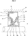
- Fig. 1 shows a cross section of a substantial part of a sealing device 1 according to the embodiment of the present invention.
- the sealing device 1 is a sealing device having a structure in which a seal lip 24 installed to a not-rotating housing 51 side slidably comes into contact with an axial end face 13a of a seal flange 13 in a rotating shaft 61 side, and is a sealing device (an oil seal for an engine) sealing so as to prevent a sealed fluid (an oil) in a machine inner side (an oil side) A from leaking out to a machine outer side (an atmospheric air side) B between a housing (a seal housing) 51 and a rotating shaft 61 which is inserted into a shaft hole 52 provided in the housing 51.
- a sealing device an oil seal for an engine
- the sealing device 1 is constructed by a combination of a lip seal member 21 which is installed to an inner periphery of the shaft hole 52 in the housing 51, and a slinger 11 which is installed to an outer periphery of the rotating shaft 61, the lip seal member 21 is provided with a seal lip 24 described in claim 1, and the slinger 11 is provided with a seal flange described in claim 1 as a flange portion 13.
- the slinger 11 is made of a rigid material such as metal, integrally has a sleeve portion 12 which is fixed (fitted) to an outer peripheral surface of the rotating shaft 61, and an outward flange portion 13 which is provided in one end portion (a machine inner side end portion) of the sleeve portion 12 in an axial direction, and is provided in a machine outer side end face 13a corresponding to the other end face of the flange portion 13 in the axial direction with a thread groove 15 which achieves an action of pushing back the sealed fluid toward an outer peripheral side (the machine inner side A) by achieving a fluid pumping action caused by centrifugal force when the rotating shaft 61 rotates, as shown in Fig. 2 .
- An arrow e denotes a rotating direction of the rotating shaft 61.
- the lip seal member 21 has an attaching ring 22 which is fixed (fitted) to an inner peripheral surface of a shaft hole 52 in the housing 51 and is made of the rigid material such as the metal, and a rubber-like elastic body 23 which is attached (vulcanization bonded) to the attaching ring 22, and is integrally provided with a seal lip (an end face lip) 24 which is slidably brought into contact with the machine outer side end face 13a of the flange portion 13 in the slinger 11 by the rubber-like elastic body 23, and an oil recovery lip 25 which is not in contact with the slinger 11.
- a dust lip 26 slidably coming into contact with the outer peripheral surface of the sleeve portion 12 in the slinger 11 is assembled in relation to the rubber-like elastic body 23.
- the oil recovery lip 25 is arranged in the machine outer side B of the seal lip 24, and the dust lip 26 is arranged further in the machine outer side B of the oil recovery lip 25.
- the seal lip 24 is provided diagonally toward the machine inner side A and an outer side in a radial direction in such a manner as to be increased its diameter little by little from a base end portion 24a thereof to a leading end portion 24b, and is in contact with the machine outer side end face 13a of the flange portion 13 in an inner peripheral surface of the leading end portion 24b. Further, a predetermined interference (contact surface pressure) is set in relation to the contact. Therefore, the seal lip 24 is elastically in contact with the machine outer side end face 13a of the flange portion 13 with the predetermined interference in the inner peripheral surface of the leading end portion 24b thereof.
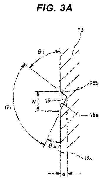
- the thread groove 15 achieving the fluid pumping action is shown in detail in Fig. 3A .
- a cross sectional shape of the thread groove 15 in a longitudinally perpendicular direction is formed into a scalene triangle having a groove opening portion as a base. More specifically, the thread groove 15 is provided with an inner peripheral side inclined surface 15a which forms a long side of the scalene triangle and is formed into a linear cross section, and an outer peripheral side inclined surface 15b which forms a short side of the scalene triangle and is formed into the linear cross section in the same manner, and an angle of incline ⁇ 3 of the inner peripheral side inclined surface 15a in relation to the machine outer side end face 13a is set to be smaller than an angle of incline ⁇ 4 of the outer peripheral side inclined surface 15b in relation to the machine outer side end face 13a.
- an angle ⁇ 5 is set to a range of 0 degree ⁇ 3 degrees, the angle ⁇ 5 being formed by an inner peripheral surface of the leading end portion 24b of the seal lip 24 and the inner peripheral side inclined surface 15a of the thread groove 15 in a state in which the leading end portion 24b of the seal lip 24 enters into the thread groove 15 as shown in Fig. 3B . Therefore, a magnitude (an opening cross sectional area) of a clearance c formed between the inner peripheral surface of the leading end 24b of the seal lip 24 and the inner surface of the thread groove 15 is set to be smaller in the thread groove 15 in Fig. 3A and 3B than in the thread groove 104 in Figs.
- the seal lip 24 is in contact with the machine outer side end face 13a of the flange portion 13 in the leading end portion 24b thereof.
- the rotating shaft 61 rotates in this state and the flange portion 13 rotates in a driven manner, the flange portion 13 rotating together with the rotating shaft 61 achieves the fluid shake-off action caused by the centrifugal force, and the thread groove 15 achieves the fluid pumping action caused by the centrifugal force.
- the sealed fluid is going to leak along the thread groove 15.
- the angle ⁇ 5 is set to the range of 0 degree ⁇ 3 degrees, the angle ⁇ 5 being formed by the inner peripheral surface of the leading end portion 24b of the seal lip 24 and the inner peripheral side inclined surface 15a of the thread groove 15 in the state in which the leading end portion 24b of the seal lip 24 enters into the thread groove 15 as mentioned above, and the magnitude of the clearance c formed between the inner peripheral surface of the leading end portion 24b of the seal lip 24 and the inner surface of the thread groove 15 is set to be small, the cross sectional area of the leakage flow path is set to be small, and the sealed fluid is accordingly hard to leak. Further, since the micro clearance c ( Fig.
- a second embodiment is an embodiment according to the first invention of the present application.
- the cross sectional shape of the thread groove 15 is formed into the scalene triangle so that the angle ⁇ 5 formed by the inner peripheral surface of the leading end portion 24b of the seal lip 24 and the inner peripheral side inclined surface 15a of the thread groove 15 is set to the range of 0 degree ⁇ 3 degrees, in the state in which the groove opening angle ⁇ 1 of the thread groove 15 is maintained in the vicinity of 113 degrees in the same manner as the conventional structure.
- the angle ⁇ 5 formed by the inner peripheral surface of the leading end portion 24b of the seal lip 24 and the inner peripheral side inclined surface 15a of the thread groove 15 can be set to the range of 0 degree ⁇ 3 degrees in the state in which the cross sectional shape of the thread groove 15 is set to the isosceles triangle.
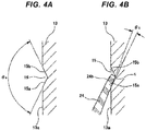
- a groove opening angle ⁇ 6 of the thread groove 15 is set to a greater angle than the conventional one, for example, 130 degrees as well as the cross sectional shape of the thread groove 15 is set to the isosceles triangle.
- the angle ⁇ 5 formed by the inner peripheral surface of the leading end portion 24b of the seal lip 24 and the inner peripheral side inclined surface 15a of the thread groove 15 is set to the range of 0 degree ⁇ 3 degrees.
- a micro clearance c ( Fig. 4B ) is formed between the inner surface of the thread groove 15 and the seal lip 24 in this example, there is fear that the sealed fluid leaks therethrough.
- the sealed fluid (the oil) is stuck fast to the periphery of the clearance c due to the surface tension in the micro clearance c, the sealed fluid hardly flows within the thread groove 15. Therefore, it is possible to approximately completely prevent the static leakage.
- a third embodiment is an embodiment according to the second invention of the present application.
- the number of the thread groove 15 is increased to three from one in the first and second embodiment, and a groove depth d, a groove width w and a cross sectional area of each of the thread grooves 15 are alternatively set to be small. Since the leading end portion 24b of the seal lip 24 enters into any one thread groove 15 among three thread grooves 15 so as to form the clearance c, the cross sectional area of the clearance c becomes small.
- a fourth embodiment is an embodiment according to the second invention of the present application.
- the thread groove 15 is formed in a process grid level and the number of the thread grooves 15 is accordingly increased to plural number from one.
- the groove depth d, the groove width w and the cross sectional area of each of the thread grooves 15 are set to be small. Since the leading end portion 24b of the seal lip 24 enters into any one thread groove 15 among a lot of thread grooves 15 so as to form the clearance c, the cross sectional area of the clearance c becomes small.
- the sealed fluid is hard to flow within the thread groove 15. As a result, it is possible to inhibit the static leakage from being generated.
- the angle formed by the inner peripheral surface of the leading end portion 24b of the seal lip 24 and the inner peripheral side inclined surface 15a of the thread groove 15 may be set to the range of 0 degree ⁇ 3 degrees in a state in which the cross sectional area of each of the thread grooves 15 is made small as well as the number of the thread grooves 15 is increased.
- a fifth embodiment is an embodiment according to a third invention of the present application.
- the angle of the thread groove 15 is set so as to satisfy the following relationship: ⁇ in ⁇ ⁇ in and ⁇ out ⁇ ⁇ out in which ⁇ in is an inner peripheral side angle (an angle formed with respect to the slinger end face) of the thread groove and ⁇ out is an outer peripheral side angle, as well as ⁇ in is an inner peripheral side contact angle (an angle formed with respect to the slinger end face) of the seal lip, and ⁇ out is an outer peripheral side contact angle thereof, when a leading end of the seal lip is positioned in a groove bottom portion of the thread groove.
- the angle of the thread groove 15 is set so as to satisfy the following relationship: ⁇ in ⁇ ⁇ in and ⁇ out ⁇ ⁇ out in which ⁇ in is an inner peripheral side angle (an angle formed with respect to the slinger end face 13a) of the thread groove 15 and ⁇ out is an outer peripheral side angle, as well as ⁇ in is an inner peripheral side contact angle (an angle formed with respect to the slinger end face 13a) of the seal lip 24, and ⁇ out is an outer peripheral side contact angle thereof, when an inner peripheral side corner portion 24e of a leading end portion 24b of the seal lip 24 (a position where the inner peripheral surface 24c of the seal lip 24 and the leading end face (the thickness surface) 24d intersect) exists at a position of the groove bottom portion 15c of the thread groove 15 having the triangular cross sectional shape (a position where the inner peripheral side inclined surface 15a of the thread groove 15 and the outer peripheral side inclined surface 15b intersect).
- ⁇ in is about 20 degrees
- ⁇ out is about 70 degrees
- ⁇ in and ⁇ out are set as shown in the following Table 1.
- Table 1 Fifth embodiment First comparative example Second comparative example Third comparative example ⁇ in 15° 15° 30° 30° ⁇ out 40° 80° 40° 80°
- the leading end portion 24b of the seal lip 24 continuously comes into contact with the inner peripheral side inclined surface 15a and the outer peripheral side inclined surface 15b of the thread groove 15 from the inner peripheral side toward the outer peripheral side without pause circumferentially in such a manner as to go over the inner peripheral side inclined surface 15a and the outer peripheral side inclined surface 15b.
- the sealed fluid the oil
- the first comparative example shown in Fig. 7A corresponds to the case that ⁇ out ⁇ ⁇ out is not established.
- the leading end portion 24b of the seal lip 24 does not come into contact with the outer peripheral side inclined surface 15b of the thread groove 15, the clearance is generated.
- the second comparative example shown in Fig. 7B corresponds to the case that ⁇ in ⁇ ⁇ in is not established.
- the clearance is generated.
- the third comparative example shown in Fig. 7C corresponds to the case that ⁇ out ⁇ ⁇ out is not established and ⁇ in ⁇ ⁇ in is not established.
- the clearance is generated.
- the angle formed by the inner peripheral surface 24c of the leading end portion 24b of the seal lip 24 and the inner peripheral side inclined surface 15a of the thread groove 15 may be set to the range of 0 degree ⁇ 3 degrees in the state in which the expression (1) mentioned above is established.
Landscapes
- Engineering & Computer Science (AREA)
- General Engineering & Computer Science (AREA)
- Mechanical Engineering (AREA)
- Physics & Mathematics (AREA)
- Fluid Mechanics (AREA)
- Sealing With Elastic Sealing Lips (AREA)
- Sealing Devices (AREA)
Abstract
Description
- The present invention relates to a sealing device according to a sealing technique. The sealing device according to the present invention is used as an oil seal for rotation, for example, in a field associated to the motor vehicle or a field of a general purpose machine.
- Conventionally, there has been known a
sealing device 101 having a structure in which aseal lip 102 installed to a not-rotatinghousing 51 side slidably comes into contact with anaxial end face 103a of aseal flange 103 in a rotatingshaft 61 side, as shown inFig. 8A . Theaxial end face 103a of theseal flange 103 is provided with athread groove 104 which achieves a fluid pumping action caused by a centrifugal force when the rotatingshaft 61 rotates, as shown inFig. 8B , and theseal lip 102 slidably comes into contact with theaxial end face 103a provided with thethread groove 104. - In the
sealing device 101, theseal flange 103 rotating together with the rotatingshaft 61 achieves a fluid shake-off action caused by the centrifugal force, and thethread groove 104 achieves the fluid pumping action caused by the centrifugal force, when the rotatingshaft 61 rotates. As a result, it is possible to inhibit the sealed fluid in a machine inner side A from leaking out to a machine outer side B after passing a contact portion between theseal lip 102 and theseal flange 103. - Patent Document 1: Japanese Unexamined Patent Publication No.
2014-137129 - However, in the
conventional sealing device 101 mentioned above, a further functional improvement is required in the following point. - More specifically, in the
sealing device 101, theseal flange 103 rotating together with the rotatingshaft 61 achieves the fluid shake-off action caused by the centrifugal force and thethread groove 104 achieves the fluid pumping action caused by the centrifugal force as mentioned above, when the rotatingshaft 61 rotates. As a result, it is possible to inhibit the sealed fluid in the machine inner side A from leaking out to the machine outer side B. However, in the case that the rotation of the rotatingshaft 61 stops, the centrifugal force disappears and both the actions disappear. Therefore, the sealed fluid may pass through the contact portion through thethread groove 104 and leak out to the machine outer side B (possibility of generation of so-called static leakage). - In the
sealing device 101 mentioned above, a cross sectional shape of thethread groove 104 is formed into an isosceles triangle having a groove opening portion as a base, and thethread groove 104 is provided with an inner peripheral sideinclined surface 104a and an outer peripheral sideinclined surface 104b as an inner surface thereof, as shown inFig. 9A in an enlarged manner. Further, as shown inFig. 9B , in the case that theseal lip 102 is combined with thethread groove 104 and the leadingend portion 102a of theseal lip 102 enters into thethread groove 104, a comparatively large angle θ2 is formed between the inner peripheral surface of the leadingend portion 102a of theseal lip 102 and the inner peripheral sideinclined surface 104a in an entering state, and a clearance c having a comparatively large cross sectional area is accordingly formed between the inner peripheral surface of the leadingend portion 102a of theseal lip 102 and the inner surface of thethread groove 104. As a result, the static leakage is generated by setting the comparatively large clearance c as the leakage flow path. A groove opening angle θ1 of thethread groove 104 having the isosceles triangle in the cross section is often in the vicinity of 113 degrees and the angle θ2 between the inner peripheral surface of the leadingend portion 102a of theseal lip 102 and the inner peripheral sideinclined surface 104a is often equal to or more than 10 degrees. - The present invention is made by taking the above points into consideration, and an object of the present invention is to provide a sealing device having a combination of a seal lip and a seal flange which slidably come into contact with each other, and provided with a thread groove in an axial end face of the seal flange, wherein the sealing device can suppress generation of a static leakage.
- The present invention employs the following means for achieving the above object.
- More specifically, a first invention (hereinafter, refer also to as the first invention of the present application) is a sealing device having a structure in which a seal lip installed to a not-rotating housing side slidably comes into contact with an axial end face of a seal flange in a rotating shaft side, and provided with a thread groove which achieves a fluid pumping action at the rotating time in an axial end face of the seal flange, wherein the thread groove is provided with an inner peripheral side inclined surface as a part of an inner surface thereof, and an angle formed between an inner peripheral surface of a leading end portion of the seal lip and the inner peripheral side inclined surface is set to a range of 0 degree ±3 degrees.
- In the sealing device having the structure mentioned above, the angle formed by the inner peripheral surface of the leading end portion in the seal lip and the inner peripheral side inclined surface of the thread groove is set to the range of 0 degree and ±3 degrees in the state in which the leading end portion of the seal lip enters into the thread groove which achieves the fluid pumping action. As a result, any clearance is not formed between the inner peripheral surface of the leading end portion in the seal lip and the inner surface of the thread groove, or the magnitude of the clearance (the cross sectional area of the opening) is reduced in comparison with the conventional art in
Figs. 8A and 8b , andFigs. 9A and 9B in conjunction with the reduction of the angle even in the case that the clearance is formed. Therefore, the leakage flow path disappears, or the magnitude of the leakage flow path is reduced. Accordingly, the sealed fluid is hard to flow, and the static leakage is suppressed. - The thread groove is not particularly limited its cross sectional shape, as long as the thread groove is provided with the inner peripheral side inclined surface as a part of the inner surface thereof. For example, the cross sectional shape may be formed into a scalene triangle or an isosceles triangle in which a groove opening portion is set to a base.
- The second invention (hereinafter, refer also to as the second invention of the present application) is a sealing device having a structure in which a seal lip installed to a not-rotating housing side slidably comes into contact with an axial end face of a seal flange in a rotating shaft side, and provided with a thread groove which achieves a fluid pumping action at the rotating time in an axial end face of the seal flange, wherein the thread groove is constructed by a plurality of thread grooves, or is constructed by a lot of thread grooves which are formed with a magnitude of a process grid level.
- In the sealing device having the structure mentioned above, a plurality of thread grooves are provided, or a lot of thread grooves formed with the magnitude of the process grid level are provided. A cross sectional area per one thread groove is set to be small in comparison with the conventional art in
Figs. 8A and 8B toFigs. 9A and 9B mentioned above. Therefore, even in the case that any clearance is formed between the inner peripheral surface of the leading end portion in the seal lip and the inner surface of the thread groove, the magnitude of the clearance (the cross sectional area of the opening) is reduced, and the magnitude of the leakage flow path is reduced. As a result, the sealed fluid is hard to flow, and the static leakage is suppressed. - The third invention (hereinafter, refer also to as the third invention of the present application) is a sealing device having a structure in which a seal lip installed to a not-rotating housing side slidably comes into contact with an axial end face of a seal flange in a rotating shaft side, and provided with a thread groove which achieves a fluid pumping action at the rotating time in an axial end face of the seal flange, wherein the following relationship is established:

- In the sealing device having the structure mentioned above, since the relationship of the above expression (1) is established, any clearance is not formed between the inner peripheral surface of the leading end portion in the seal lip and the inner peripheral side inclined surface of the thread groove. Therefore, since the leakage flow path disappears, the sealed fluid is hard to flow, and the static leakage is suppressed.
- In the present invention, in the sealing device having the combination of the seal lip and the seal flange which slidably come into contact with each other, and provided with the thread groove in the axial end face of the seal flange, it is possible to inhibit the static leakage from being generated, and it is possible to inhibit the sealed fluid from leaking out even when the rotating shaft stands still as well as the rotating shaft rotates.
-
-
Fig. 1 is a cross sectional view of a substantial part of a sealing device according to a first embodiment of a first invention of the present application; -
Fig. 2 is an explanatory view of a thread groove which is provided in the sealing device; -
Fig. 3A is an enlarged cross sectional view of the thread groove; -
Fig. 3B is an enlarged cross sectional view of a state in which a seal lip is combined with the thread groove; -
Figs. 4A and 4B are explanatory views of a thread groove which is provided in a sealing device according to a second embodiment of the first invention of the present application, in whichFig. 4A is a cross sectional view of the thread groove, andFig. 4B is a cross sectional view of a state in which the seal lip is combined with the thread groove; -
Fig. 5A is a cross sectional view of a state in which the seal lip is combined with a thread groove which is provided in a sealing device according to a third embodiment of a second invention of the present application; -
Fig. 5B is a cross sectional view of a state in which the seal lip is combined with a thread groove which is provided in a sealing device according to a fourth embodiment of the second invention of the present application; -
Fig. 6 is a cross sectional view of a state in which the seal lip is combined with a thread groove which is provided in a sealing device according to a fifth embodiment of a third invention of the present application; -
Figs. 7A, 7B and 7C are views showing sealing devices according to comparative examples, in whichFig. 7A is a cross sectional view of a state in which the seal lip is combined with a thread groove which is provided in the sealing device according to the first comparative example,Fig. 7B is a cross sectional view of a state in which the seal lip is combined with a thread groove which is provided in the sealing device according to the second comparative example, andFig. 7C is a cross sectional view of a state in which the seal lip is combined with a thread groove which is provided in the sealing device according to the third comparative example; -
Figs. 8A and 8B are views showing a sealing device according to the conventional example, in whichFig. 8A is a cross sectional view of a substantial part of the sealing device according to the conventional example, andFig. 8B is an explanatory view of a thread groove which is provided in the sealing device; -
Fig. 9A is an enlarged cross sectional view of the thread groove; and -
Fig. 9B is an enlarged cross sectional view of a state in which the seal lip is combined with the thread groove. - Next, a description will be given of embodiments according to the present invention with reference to the accompanying drawings.
- The first embodiment is an embodiment according to the first invention of the present application.
-
Fig. 1 shows a cross section of a substantial part of a sealing device 1 according to the embodiment of the present invention. - The sealing device 1 according to the embodiment is a sealing device having a structure in which a
seal lip 24 installed to a not-rotatinghousing 51 side slidably comes into contact with anaxial end face 13a of aseal flange 13 in arotating shaft 61 side, and is a sealing device (an oil seal for an engine) sealing so as to prevent a sealed fluid (an oil) in a machine inner side (an oil side) A from leaking out to a machine outer side (an atmospheric air side) B between a housing (a seal housing) 51 and arotating shaft 61 which is inserted into ashaft hole 52 provided in thehousing 51. Further, the sealing device 1 is constructed by a combination of alip seal member 21 which is installed to an inner periphery of theshaft hole 52 in thehousing 51, and aslinger 11 which is installed to an outer periphery of therotating shaft 61, thelip seal member 21 is provided with aseal lip 24 described in claim 1, and theslinger 11 is provided with a seal flange described in claim 1 as aflange portion 13. - The
slinger 11 is made of a rigid material such as metal, integrally has asleeve portion 12 which is fixed (fitted) to an outer peripheral surface of therotating shaft 61, and anoutward flange portion 13 which is provided in one end portion (a machine inner side end portion) of thesleeve portion 12 in an axial direction, and is provided in a machine outerside end face 13a corresponding to the other end face of theflange portion 13 in the axial direction with athread groove 15 which achieves an action of pushing back the sealed fluid toward an outer peripheral side (the machine inner side A) by achieving a fluid pumping action caused by centrifugal force when the rotatingshaft 61 rotates, as shown inFig. 2 . An arrow e denotes a rotating direction of therotating shaft 61. - Meanwhile, the
lip seal member 21 has an attachingring 22 which is fixed (fitted) to an inner peripheral surface of ashaft hole 52 in thehousing 51 and is made of the rigid material such as the metal, and a rubber-likeelastic body 23 which is attached (vulcanization bonded) to the attachingring 22, and is integrally provided with a seal lip (an end face lip) 24 which is slidably brought into contact with the machine outerside end face 13a of theflange portion 13 in theslinger 11 by the rubber-likeelastic body 23, and anoil recovery lip 25 which is not in contact with theslinger 11. Further, adust lip 26 slidably coming into contact with the outer peripheral surface of thesleeve portion 12 in theslinger 11 is assembled in relation to the rubber-likeelastic body 23. Theoil recovery lip 25 is arranged in the machine outer side B of theseal lip 24, and thedust lip 26 is arranged further in the machine outer side B of theoil recovery lip 25. - The
seal lip 24 is provided diagonally toward the machine inner side A and an outer side in a radial direction in such a manner as to be increased its diameter little by little from abase end portion 24a thereof to aleading end portion 24b, and is in contact with the machine outerside end face 13a of theflange portion 13 in an inner peripheral surface of theleading end portion 24b. Further, a predetermined interference (contact surface pressure) is set in relation to the contact. Therefore, theseal lip 24 is elastically in contact with the machine outerside end face 13a of theflange portion 13 with the predetermined interference in the inner peripheral surface of theleading end portion 24b thereof. - The
thread groove 15 achieving the fluid pumping action is shown in detail inFig. 3A . A cross sectional shape of thethread groove 15 in a longitudinally perpendicular direction is formed into a scalene triangle having a groove opening portion as a base. More specifically, thethread groove 15 is provided with an inner peripheral side inclinedsurface 15a which forms a long side of the scalene triangle and is formed into a linear cross section, and an outer peripheral side inclinedsurface 15b which forms a short side of the scalene triangle and is formed into the linear cross section in the same manner, and an angle of incline θ3 of the inner peripheral side inclinedsurface 15a in relation to the machine outerside end face 13a is set to be smaller than an angle of incline θ4 of the outer peripheral side inclinedsurface 15b in relation to the machine outerside end face 13a. As a result, an angle θ5 is set to a range of 0 degree ±3 degrees, the angle θ5 being formed by an inner peripheral surface of theleading end portion 24b of theseal lip 24 and the inner peripheral side inclinedsurface 15a of thethread groove 15 in a state in which theleading end portion 24b of theseal lip 24 enters into thethread groove 15 as shown inFig. 3B . Therefore, a magnitude (an opening cross sectional area) of a clearance c formed between the inner peripheral surface of theleading end 24b of theseal lip 24 and the inner surface of thethread groove 15 is set to be smaller in thethread groove 15 inFig. 3A and 3B than in thethread groove 104 inFigs. 9A and 9B , under a condition that a groove width w is fixed (or a groove depth d is fixed) and the groove opening angle θ1 is fixed (for example, 113 degrees), in comparison with thethread groove 104 having the isosceles triangular cross section shown inFigs. 9A and 9B . - In the sealing device 1 having the structure mentioned above, the
seal lip 24 is in contact with the machine outerside end face 13a of theflange portion 13 in theleading end portion 24b thereof. When therotating shaft 61 rotates in this state and theflange portion 13 rotates in a driven manner, theflange portion 13 rotating together with the rotatingshaft 61 achieves the fluid shake-off action caused by the centrifugal force, and thethread groove 15 achieves the fluid pumping action caused by the centrifugal force. As a result, it is possible to inhibit the sealed fluid in the machine inner side A from passing through the contact portion between theseal lip 24 and theflange portion 13 and leaking out to the machine outer side B. - Further, when the rotating
shaft 61 stands still, the sealed fluid is going to leak along thethread groove 15. However, since the angle θ5 is set to the range of 0 degree ±3 degrees, the angle θ5 being formed by the inner peripheral surface of theleading end portion 24b of theseal lip 24 and the inner peripheral side inclinedsurface 15a of thethread groove 15 in the state in which theleading end portion 24b of theseal lip 24 enters into thethread groove 15 as mentioned above, and the magnitude of the clearance c formed between the inner peripheral surface of theleading end portion 24b of theseal lip 24 and the inner surface of thethread groove 15 is set to be small, the cross sectional area of the leakage flow path is set to be small, and the sealed fluid is accordingly hard to leak. Further, since the micro clearance c (Fig. 3B ) is formed between the inner surface of thethread groove 15 and theseal lip 24 in the embodiment, there is fear that the sealed fluid leaks therethrough, however, since the sealed fluid (the oil) is stuck fast to the periphery of the clearance c on the basis of a surface tension in the micro clearance c, the sealed fluid hardly flows within thethread groove 15. Therefore, it is possible to almost completely prevent the static leakage. - Therefore, according to the above description, it is possible to inhibit the static leakage from being generated while maintaining a sealing performance at the rotating time.
- A second embodiment is an embodiment according to the first invention of the present application.
- In the first embodiment mentioned above, the cross sectional shape of the
thread groove 15 is formed into the scalene triangle so that the angle θ5 formed by the inner peripheral surface of theleading end portion 24b of theseal lip 24 and the inner peripheral side inclinedsurface 15a of thethread groove 15 is set to the range of 0 degree ±3 degrees, in the state in which the groove opening angle θ1 of thethread groove 15 is maintained in the vicinity of 113 degrees in the same manner as the conventional structure. However, if the groove opening angle θ1 of thethread groove 15 is expanded from the vicinity of 113 degrees which is the same as the conventional angle, the angle θ5 formed by the inner peripheral surface of theleading end portion 24b of theseal lip 24 and the inner peripheral side inclinedsurface 15a of thethread groove 15 can be set to the range of 0 degree ±3 degrees in the state in which the cross sectional shape of thethread groove 15 is set to the isosceles triangle. - As such an example as the above, in
Figs. 4A and 4B which are shown as the second embodiment, a groove opening angle θ6 of thethread groove 15 is set to a greater angle than the conventional one, for example, 130 degrees as well as the cross sectional shape of thethread groove 15 is set to the isosceles triangle. As a result, the angle θ5 formed by the inner peripheral surface of theleading end portion 24b of theseal lip 24 and the inner peripheral side inclinedsurface 15a of thethread groove 15 is set to the range of 0 degree ±3 degrees. - Therefore, even in the example in
Figs. 4A and 4B , since the magnitude of the clearance c formed between the inner peripheral surface of theleading end portion 24b of theseal lip 24 and the inner surface of thethread groove 15 is set to be small, the cross sectional area of the leakage flow path becomes small, and the sealed fluid is accordingly hard to leak. - Further, since a micro clearance c (
Fig. 4B ) is formed between the inner surface of thethread groove 15 and theseal lip 24 in this example, there is fear that the sealed fluid leaks therethrough. However, since the sealed fluid (the oil) is stuck fast to the periphery of the clearance c due to the surface tension in the micro clearance c, the sealed fluid hardly flows within thethread groove 15. Therefore, it is possible to approximately completely prevent the static leakage. - Therefore, according to the description mentioned above, it is possible to inhibit the static leakage from being generated while maintaining the sealing performance at the rotating time.
- In order to increase the action that the sealed fluid (the oil) is stuck fast to the periphery of the clearance c due to the surface tension thereof, it is thought that a surface area is enlarged by the provision of a satin finished portion on an inner surface of the
thread groove 15 and a surface of theseal lip 24 which construct the periphery of the clearance c according to a shot blasting method. - A third embodiment is an embodiment according to the second invention of the present application.
- In order to set the magnitude of the clearance c formed between the inner peripheral surface of the
leading end portion 24b of theseal lip 24 and the inner surface of thethread groove 15 to be small, it is thought to make a cross sectional area of each of thethread grooves 15 small as well as increasing the number of thethread groove 15 in addition to the first and second embodiments mentioned above. Even in the case that the cross sectional area of each of thethread grooves 15 is made small as well as the number of thethread grooves 15 is increased as mentioned above, the surface tension of the sealed fluid tends to be generated, and the sealed fluid is hard to flow within thethread groove 15. As a result, it is possible to inhibit the static leakage from being generated. - In an example in
Fig. 5A which is shown as the third embodiment, the number of thethread groove 15 is increased to three from one in the first and second embodiment, and a groove depth d, a groove width w and a cross sectional area of each of thethread grooves 15 are alternatively set to be small. Since theleading end portion 24b of theseal lip 24 enters into any onethread groove 15 among threethread grooves 15 so as to form the clearance c, the cross sectional area of the clearance c becomes small. - A fourth embodiment is an embodiment according to the second invention of the present application.
- In an example in
Fig. 5B which is shown as the fourth embodiment, thethread groove 15 is formed in a process grid level and the number of thethread grooves 15 is accordingly increased to plural number from one. Alternatively, the groove depth d, the groove width w and the cross sectional area of each of thethread grooves 15 are set to be small. Since theleading end portion 24b of theseal lip 24 enters into any onethread groove 15 among a lot ofthread grooves 15 so as to form the clearance c, the cross sectional area of the clearance c becomes small. - Therefore, even in these examples, the sealed fluid is hard to flow within the
thread groove 15. As a result, it is possible to inhibit the static leakage from being generated. - Further, the angle formed by the inner peripheral surface of the
leading end portion 24b of theseal lip 24 and the inner peripheral side inclinedsurface 15a of thethread groove 15 may be set to the range of 0 degree ±3 degrees in a state in which the cross sectional area of each of thethread grooves 15 is made small as well as the number of thethread grooves 15 is increased. - A fifth embodiment is an embodiment according to a third invention of the present application.
- In order to suppress the static leakage, it is effective to set the angle of the
thread groove 15 as follows. - More specifically, the angle of the
thread groove 15 is set so as to satisfy the following relationship:
- According to this structure, it is possible to prevent the static leakage while maintaining the same pumping amount as the conventional one by the thread groove portion of the slinger. As a result, it is possible to secure a stable sealing performance over the long term.
- In an example in
Fig. 6 which is shown as the fifth embodiment corresponding to the example, the angle of thethread groove 15 is set so as to satisfy the following relationship:
slinger end face 13a) of thethread groove 15 and Φout is an outer peripheral side angle, as well as θin is an inner peripheral side contact angle (an angle formed with respect to theslinger end face 13a) of theseal lip 24, and θout is an outer peripheral side contact angle thereof, when an inner peripheralside corner portion 24e of aleading end portion 24b of the seal lip 24 (a position where the innerperipheral surface 24c of theseal lip 24 and the leading end face (the thickness surface) 24d intersect) exists at a position of thegroove bottom portion 15c of thethread groove 15 having the triangular cross sectional shape (a position where the inner peripheral side inclinedsurface 15a of thethread groove 15 and the outer peripheral side inclinedsurface 15b intersect). - Comparison with comparative examples which do not satisfy the relationship of the expression (1) is as follows.
- In all of the fifth embodiment shown in
Fig. 6 , the first comparative example shown inFig. 7A , the second comparative example shown inFig. 7B and the third comparative example shown inFig. 7C , Φin is about 20 degrees, and Φout is about 70 degrees. θin and θout are set as shown in the following Table 1.Table 1 Fifth embodiment First comparative example Second comparative example Third comparative example θin 15° 15° 30° 30° θout 40° 80° 40° 80° - In the fifth embodiment shown in
Fig. 6 , theleading end portion 24b of theseal lip 24 continuously comes into contact with the inner peripheral side inclinedsurface 15a and the outer peripheral side inclinedsurface 15b of thethread groove 15 from the inner peripheral side toward the outer peripheral side without pause circumferentially in such a manner as to go over the inner peripheral side inclinedsurface 15a and the outer peripheral side inclinedsurface 15b. As a result, the sealed fluid (the oil) has not chance of going around the inner peripheral side of theseal lip 24. - On the contrary, the first comparative example shown in
Fig. 7A corresponds to the case that θout ≦ Φout is not established. In this groove shape, since theleading end portion 24b of theseal lip 24 does not come into contact with the outer peripheral side inclinedsurface 15b of thethread groove 15, the clearance is generated. - The second comparative example shown in
Fig. 7B corresponds to the case that θin ≦ Φin is not established. In this groove shape, since theleading end portion 24b of theseal lip 24 does not come into contact with the inner peripheral side inclinedsurface 15a of thethread groove 15, the clearance is generated. - The third comparative example shown in
Fig. 7C corresponds to the case that θout ≦ Φout is not established and θin ≦ Φin is not established. In this groove shape, since theleading end portion 24b of theseal lip 24 does not come into contact with both of the inner peripheral side inclinedsurface 15a and the outer peripheral side inclinedsurface 15b of thethread groove 15, the clearance is generated. - Therefore, the static leakage can be sufficiently suppressed only in the case that the expression (1) mentioned above is established.
- Further, in the fifth embodiment, the angle formed by the inner
peripheral surface 24c of theleading end portion 24b of theseal lip 24 and the inner peripheral side inclinedsurface 15a of thethread groove 15 may be set to the range of 0 degree ±3 degrees in the state in which the expression (1) mentioned above is established. -
- 1
- sealing device
- 11
- slinger
- 12
- sleeve portion
- 13
- flange portion (seal flange)
- 13a
- machine outer side end face (axial end face)
- 15
- thread groove
- 15a
- inner peripheral side inclined surface
- 15b
- outer peripheral side inclined surface
- 15c
- groove bottom portion
- 21
- lip seal member
- 22
- attachment ring
- 23
- rubber-like elastic body
- 24
- seal lip
- 24a
- base end portion
- 24b
- leading end portion
- 24c
- inner peripheral surface
- 24d
- leading end face
- 24e
- inner peripheral side corner portion
- 25
- oil recovery lip
- 26
- dust lip
- 51
- housing
- 52
- shaft hole
- 61
- rotating shaft
- C
- clearance
- A
- machine inner side
- B
- machine outer side
Claims (2)
- A sealing device comprising:a structure in which a seal lip installed to a not-rotating housing side slidably comes into contact with an axial end face of a seal flange in a rotating shaft side;a thread groove which achieves a fluid pumping action at the rotating time in an axial end face of the seal flange;the thread groove having an inner peripheral side inclined surface as a part of an inner surface thereof; andwith the leading end of the seal lip inserted in the thread groove, an angle formed between an inner peripheral surface of a leading end portion of the seal lip and the inner peripheral side inclined surface, the angle being set to a range of 0 degree ±3 degrees.
- The sealing device according to claim 1, wherein the thread groove is formed its cross sectional shape into a scalene triangle or an isosceles triangle.
Applications Claiming Priority (2)
| Application Number | Priority Date | Filing Date | Title |
|---|---|---|---|
| JP2015075999 | 2015-04-02 | ||
| PCT/JP2016/059546 WO2016158718A1 (en) | 2015-04-02 | 2016-03-25 | Sealing apparatus |
Publications (3)
| Publication Number | Publication Date |
|---|---|
| EP3279526A1 true EP3279526A1 (en) | 2018-02-07 |
| EP3279526A4 EP3279526A4 (en) | 2018-03-21 |
| EP3279526B1 EP3279526B1 (en) | 2019-03-06 |
Family
ID=57005843
Family Applications (1)
| Application Number | Title | Priority Date | Filing Date |
|---|---|---|---|
| EP16772599.3A Not-in-force EP3279526B1 (en) | 2015-04-02 | 2016-03-25 | Sealing apparatus |
Country Status (6)
| Country | Link |
|---|---|
| US (1) | US10544865B2 (en) |
| EP (1) | EP3279526B1 (en) |
| JP (1) | JP6033996B1 (en) |
| KR (1) | KR20170134563A (en) |
| CN (1) | CN107208802B (en) |
| WO (1) | WO2016158718A1 (en) |
Families Citing this family (13)
| Publication number | Priority date | Publication date | Assignee | Title |
|---|---|---|---|---|
| US20180372222A1 (en) * | 2015-11-24 | 2018-12-27 | Nok Corporation | Sealing device |
| US10711899B2 (en) * | 2015-11-30 | 2020-07-14 | Nok Corporation | Seal device |
| CN108138966B (en) * | 2015-11-30 | 2019-04-05 | Nok株式会社 | Sealing means |
| JP6432721B2 (en) * | 2016-11-25 | 2018-12-05 | Nok株式会社 | Sealing device |
| JP7051311B2 (en) * | 2017-05-29 | 2022-04-11 | Nok株式会社 | Sealing device |
| WO2018221727A1 (en) | 2017-06-02 | 2018-12-06 | Nok株式会社 | Sealing device |
| JP7203728B2 (en) * | 2017-07-07 | 2023-01-13 | Nok株式会社 | sealing device |
| US20190226584A1 (en) * | 2018-01-19 | 2019-07-25 | American Axle & Manufacturing, Inc. | Lip seal with air-side spring |
| US20200340588A1 (en) * | 2018-08-23 | 2020-10-29 | Nok Corporation | Sealing device and method for making slinger |
| NL2022585B1 (en) * | 2019-02-15 | 2020-08-28 | Lagersmit Sealing Solutions B V | Radial sealing system |
| IT201900020112A1 (en) * | 2019-10-31 | 2021-05-01 | Skf Ab | DYNAMIC INTERFERENCE SEALING DEVICE AND SYSTEM WITH IMPROVED CONTACT BEHAVIOR |
| JP7372842B2 (en) * | 2020-01-08 | 2023-11-01 | Nok株式会社 | Plate member with lip and canceller member |
| CN112343924A (en) * | 2020-10-29 | 2021-02-09 | 广州市昊志机电股份有限公司 | Main shaft contact type sealing structure, main shaft and machine tool |
Family Cites Families (18)
| Publication number | Priority date | Publication date | Assignee | Title |
|---|---|---|---|---|
| US4573690A (en) * | 1984-12-13 | 1986-03-04 | General Motors Corporation | Sealing surface and method |
| JPH02113173A (en) | 1988-10-20 | 1990-04-25 | Nok Corp | Sealing device |
| JPH0743550Y2 (en) | 1989-10-11 | 1995-10-09 | エヌオーケー株式会社 | Sealing device |
| KR101242051B1 (en) * | 2004-03-23 | 2013-03-12 | 엔오케이 가부시키가이샤 | Sealing device with rotation detection element |
| JP2007239987A (en) * | 2006-02-10 | 2007-09-20 | Nsk Ltd | Seal device and rolling bearing unit with seal device |
| JP5041137B2 (en) * | 2007-01-29 | 2012-10-03 | Nok株式会社 | Sealing device |
| JP2009191913A (en) | 2008-02-13 | 2009-08-27 | Arai Seisakusho Co Ltd | Sealing device |
| CN102046994B (en) * | 2008-05-27 | 2013-11-20 | 株式会社捷太格特 | Sealing device for rolling bearing |
| JP5234651B2 (en) * | 2008-08-29 | 2013-07-10 | 内山工業株式会社 | Sealing device |
| JP5980217B2 (en) * | 2011-09-06 | 2016-08-31 | イーグル工業株式会社 | Shaft seal device and manufacturing method thereof |
| US20130175763A1 (en) * | 2012-01-10 | 2013-07-11 | Freudenberg-Nok General Partnership | Lubricated Shaft Seal |
| JP6054135B2 (en) | 2012-10-23 | 2016-12-27 | Nok株式会社 | Oil seal |
| JP5964201B2 (en) | 2012-10-23 | 2016-08-03 | Nok株式会社 | Oil seal |
| JP6000845B2 (en) * | 2012-12-28 | 2016-10-05 | Nok株式会社 | Sealing device |
| JP2014137129A (en) * | 2013-01-18 | 2014-07-28 | Toyota Motor Corp | Seal device |
| WO2015190450A1 (en) * | 2014-06-10 | 2015-12-17 | Nok株式会社 | Seal device |
| WO2016111303A1 (en) * | 2015-01-08 | 2016-07-14 | Nok株式会社 | Sealing device |
| US10711899B2 (en) * | 2015-11-30 | 2020-07-14 | Nok Corporation | Seal device |
-
2016
- 2016-03-25 KR KR1020177031432A patent/KR20170134563A/en not_active Ceased
- 2016-03-25 US US15/559,992 patent/US10544865B2/en active Active
- 2016-03-25 EP EP16772599.3A patent/EP3279526B1/en not_active Not-in-force
- 2016-03-25 WO PCT/JP2016/059546 patent/WO2016158718A1/en not_active Ceased
- 2016-03-25 CN CN201680008191.3A patent/CN107208802B/en not_active Expired - Fee Related
- 2016-03-25 JP JP2016549171A patent/JP6033996B1/en active Active
Also Published As
| Publication number | Publication date |
|---|---|
| EP3279526A4 (en) | 2018-03-21 |
| JP6033996B1 (en) | 2016-11-30 |
| JPWO2016158718A1 (en) | 2017-04-27 |
| EP3279526B1 (en) | 2019-03-06 |
| US10544865B2 (en) | 2020-01-28 |
| WO2016158718A1 (en) | 2016-10-06 |
| CN107208802A (en) | 2017-09-26 |
| CN107208802B (en) | 2018-10-19 |
| US20180066757A1 (en) | 2018-03-08 |
| KR20170134563A (en) | 2017-12-06 |
Similar Documents
| Publication | Publication Date | Title |
|---|---|---|
| EP3279526B1 (en) | Sealing apparatus | |
| EP3244100B1 (en) | Sealing device | |
| US10683935B2 (en) | Sealing device | |
| KR102077277B1 (en) | Oil seal | |
| US10371260B2 (en) | Oil seal | |
| CN108291650B (en) | Sealing means | |
| JP6263255B2 (en) | Sealing device | |
| US10228059B2 (en) | Sealing device | |
| JP6809847B2 (en) | Sealing device | |
| CN108138965A (en) | Sealing device | |
| JP6796062B2 (en) | Gasket with filter | |
| US9803650B2 (en) | Sealing device | |
| JP2021521393A (en) | Floating ring seal | |
| US20170082203A1 (en) | Vented lift off seal assemblies | |
| JP2018004027A (en) | Sealing device | |
| US11261970B2 (en) | Sealing device |
Legal Events
| Date | Code | Title | Description |
|---|---|---|---|
| STAA | Information on the status of an ep patent application or granted ep patent |
Free format text: STATUS: THE INTERNATIONAL PUBLICATION HAS BEEN MADE |
|
| PUAI | Public reference made under article 153(3) epc to a published international application that has entered the european phase |
Free format text: ORIGINAL CODE: 0009012 |
|
| STAA | Information on the status of an ep patent application or granted ep patent |
Free format text: STATUS: REQUEST FOR EXAMINATION WAS MADE |
|
| 17P | Request for examination filed |
Effective date: 20170929 |
|
| AK | Designated contracting states |
Kind code of ref document: A1 Designated state(s): AL AT BE BG CH CY CZ DE DK EE ES FI FR GB GR HR HU IE IS IT LI LT LU LV MC MK MT NL NO PL PT RO RS SE SI SK SM TR |
|
| AX | Request for extension of the european patent |
Extension state: BA ME |
|
| A4 | Supplementary search report drawn up and despatched |
Effective date: 20180215 |
|
| RIC1 | Information provided on ipc code assigned before grant |
Ipc: F16J 15/3244 20160101ALI20180210BHEP Ipc: F16J 15/16 20060101ALI20180210BHEP Ipc: F16J 15/34 20060101ALI20180210BHEP Ipc: F16J 15/3204 20160101AFI20180210BHEP Ipc: F16J 15/3264 20160101ALI20180210BHEP |
|
| DAV | Request for validation of the european patent (deleted) | ||
| DAX | Request for extension of the european patent (deleted) | ||
| GRAP | Despatch of communication of intention to grant a patent |
Free format text: ORIGINAL CODE: EPIDOSNIGR1 |
|
| STAA | Information on the status of an ep patent application or granted ep patent |
Free format text: STATUS: GRANT OF PATENT IS INTENDED |
|
| INTG | Intention to grant announced |
Effective date: 20180910 |
|
| GRAS | Grant fee paid |
Free format text: ORIGINAL CODE: EPIDOSNIGR3 |
|
| GRAA | (expected) grant |
Free format text: ORIGINAL CODE: 0009210 |
|
| STAA | Information on the status of an ep patent application or granted ep patent |
Free format text: STATUS: THE PATENT HAS BEEN GRANTED |
|
| AK | Designated contracting states |
Kind code of ref document: B1 Designated state(s): AL AT BE BG CH CY CZ DE DK EE ES FI FR GB GR HR HU IE IS IT LI LT LU LV MC MK MT NL NO PL PT RO RS SE SI SK SM TR |
|
| REG | Reference to a national code |
Ref country code: GB Ref legal event code: FG4D |
|
| REG | Reference to a national code |
Ref country code: CH Ref legal event code: EP Ref country code: AT Ref legal event code: REF Ref document number: 1104992 Country of ref document: AT Kind code of ref document: T Effective date: 20190315 |
|
| REG | Reference to a national code |
Ref country code: DE Ref legal event code: R096 Ref document number: 602016010814 Country of ref document: DE |
|
| REG | Reference to a national code |
Ref country code: IE Ref legal event code: FG4D |
|
| REG | Reference to a national code |
Ref country code: NL Ref legal event code: MP Effective date: 20190306 |
|
| REG | Reference to a national code |
Ref country code: LT Ref legal event code: MG4D |
|
| PG25 | Lapsed in a contracting state [announced via postgrant information from national office to epo] |
Ref country code: NO Free format text: LAPSE BECAUSE OF FAILURE TO SUBMIT A TRANSLATION OF THE DESCRIPTION OR TO PAY THE FEE WITHIN THE PRESCRIBED TIME-LIMIT Effective date: 20190606 Ref country code: LT Free format text: LAPSE BECAUSE OF FAILURE TO SUBMIT A TRANSLATION OF THE DESCRIPTION OR TO PAY THE FEE WITHIN THE PRESCRIBED TIME-LIMIT Effective date: 20190306 Ref country code: SE Free format text: LAPSE BECAUSE OF FAILURE TO SUBMIT A TRANSLATION OF THE DESCRIPTION OR TO PAY THE FEE WITHIN THE PRESCRIBED TIME-LIMIT Effective date: 20190306 Ref country code: FI Free format text: LAPSE BECAUSE OF FAILURE TO SUBMIT A TRANSLATION OF THE DESCRIPTION OR TO PAY THE FEE WITHIN THE PRESCRIBED TIME-LIMIT Effective date: 20190306 |
|
| PG25 | Lapsed in a contracting state [announced via postgrant information from national office to epo] |
Ref country code: LV Free format text: LAPSE BECAUSE OF FAILURE TO SUBMIT A TRANSLATION OF THE DESCRIPTION OR TO PAY THE FEE WITHIN THE PRESCRIBED TIME-LIMIT Effective date: 20190306 Ref country code: RS Free format text: LAPSE BECAUSE OF FAILURE TO SUBMIT A TRANSLATION OF THE DESCRIPTION OR TO PAY THE FEE WITHIN THE PRESCRIBED TIME-LIMIT Effective date: 20190306 Ref country code: BG Free format text: LAPSE BECAUSE OF FAILURE TO SUBMIT A TRANSLATION OF THE DESCRIPTION OR TO PAY THE FEE WITHIN THE PRESCRIBED TIME-LIMIT Effective date: 20190606 Ref country code: GR Free format text: LAPSE BECAUSE OF FAILURE TO SUBMIT A TRANSLATION OF THE DESCRIPTION OR TO PAY THE FEE WITHIN THE PRESCRIBED TIME-LIMIT Effective date: 20190607 Ref country code: HR Free format text: LAPSE BECAUSE OF FAILURE TO SUBMIT A TRANSLATION OF THE DESCRIPTION OR TO PAY THE FEE WITHIN THE PRESCRIBED TIME-LIMIT Effective date: 20190306 Ref country code: NL Free format text: LAPSE BECAUSE OF FAILURE TO SUBMIT A TRANSLATION OF THE DESCRIPTION OR TO PAY THE FEE WITHIN THE PRESCRIBED TIME-LIMIT Effective date: 20190306 |
|
| REG | Reference to a national code |
Ref country code: AT Ref legal event code: MK05 Ref document number: 1104992 Country of ref document: AT Kind code of ref document: T Effective date: 20190306 |
|
| PG25 | Lapsed in a contracting state [announced via postgrant information from national office to epo] |
Ref country code: ES Free format text: LAPSE BECAUSE OF FAILURE TO SUBMIT A TRANSLATION OF THE DESCRIPTION OR TO PAY THE FEE WITHIN THE PRESCRIBED TIME-LIMIT Effective date: 20190306 Ref country code: AL Free format text: LAPSE BECAUSE OF FAILURE TO SUBMIT A TRANSLATION OF THE DESCRIPTION OR TO PAY THE FEE WITHIN THE PRESCRIBED TIME-LIMIT Effective date: 20190306 Ref country code: PT Free format text: LAPSE BECAUSE OF FAILURE TO SUBMIT A TRANSLATION OF THE DESCRIPTION OR TO PAY THE FEE WITHIN THE PRESCRIBED TIME-LIMIT Effective date: 20190706 Ref country code: IT Free format text: LAPSE BECAUSE OF FAILURE TO SUBMIT A TRANSLATION OF THE DESCRIPTION OR TO PAY THE FEE WITHIN THE PRESCRIBED TIME-LIMIT Effective date: 20190306 Ref country code: RO Free format text: LAPSE BECAUSE OF FAILURE TO SUBMIT A TRANSLATION OF THE DESCRIPTION OR TO PAY THE FEE WITHIN THE PRESCRIBED TIME-LIMIT Effective date: 20190306 Ref country code: SK Free format text: LAPSE BECAUSE OF FAILURE TO SUBMIT A TRANSLATION OF THE DESCRIPTION OR TO PAY THE FEE WITHIN THE PRESCRIBED TIME-LIMIT Effective date: 20190306 Ref country code: CZ Free format text: LAPSE BECAUSE OF FAILURE TO SUBMIT A TRANSLATION OF THE DESCRIPTION OR TO PAY THE FEE WITHIN THE PRESCRIBED TIME-LIMIT Effective date: 20190306 Ref country code: EE Free format text: LAPSE BECAUSE OF FAILURE TO SUBMIT A TRANSLATION OF THE DESCRIPTION OR TO PAY THE FEE WITHIN THE PRESCRIBED TIME-LIMIT Effective date: 20190306 |
|
| REG | Reference to a national code |
Ref country code: CH Ref legal event code: PL |
|
| PG25 | Lapsed in a contracting state [announced via postgrant information from national office to epo] |
Ref country code: SM Free format text: LAPSE BECAUSE OF FAILURE TO SUBMIT A TRANSLATION OF THE DESCRIPTION OR TO PAY THE FEE WITHIN THE PRESCRIBED TIME-LIMIT Effective date: 20190306 Ref country code: PL Free format text: LAPSE BECAUSE OF FAILURE TO SUBMIT A TRANSLATION OF THE DESCRIPTION OR TO PAY THE FEE WITHIN THE PRESCRIBED TIME-LIMIT Effective date: 20190306 Ref country code: LU Free format text: LAPSE BECAUSE OF NON-PAYMENT OF DUE FEES Effective date: 20190325 |
|
| REG | Reference to a national code |
Ref country code: DE Ref legal event code: R097 Ref document number: 602016010814 Country of ref document: DE |
|
| REG | Reference to a national code |
Ref country code: BE Ref legal event code: MM Effective date: 20190331 |
|
| PG25 | Lapsed in a contracting state [announced via postgrant information from national office to epo] |
Ref country code: IS Free format text: LAPSE BECAUSE OF FAILURE TO SUBMIT A TRANSLATION OF THE DESCRIPTION OR TO PAY THE FEE WITHIN THE PRESCRIBED TIME-LIMIT Effective date: 20190706 Ref country code: AT Free format text: LAPSE BECAUSE OF FAILURE TO SUBMIT A TRANSLATION OF THE DESCRIPTION OR TO PAY THE FEE WITHIN THE PRESCRIBED TIME-LIMIT Effective date: 20190306 |
|
| PLBE | No opposition filed within time limit |
Free format text: ORIGINAL CODE: 0009261 |
|
| STAA | Information on the status of an ep patent application or granted ep patent |
Free format text: STATUS: NO OPPOSITION FILED WITHIN TIME LIMIT |
|
| PG25 | Lapsed in a contracting state [announced via postgrant information from national office to epo] |
Ref country code: DK Free format text: LAPSE BECAUSE OF FAILURE TO SUBMIT A TRANSLATION OF THE DESCRIPTION OR TO PAY THE FEE WITHIN THE PRESCRIBED TIME-LIMIT Effective date: 20190306 Ref country code: CH Free format text: LAPSE BECAUSE OF NON-PAYMENT OF DUE FEES Effective date: 20190331 Ref country code: IE Free format text: LAPSE BECAUSE OF NON-PAYMENT OF DUE FEES Effective date: 20190325 Ref country code: MC Free format text: LAPSE BECAUSE OF FAILURE TO SUBMIT A TRANSLATION OF THE DESCRIPTION OR TO PAY THE FEE WITHIN THE PRESCRIBED TIME-LIMIT Effective date: 20190306 Ref country code: LI Free format text: LAPSE BECAUSE OF NON-PAYMENT OF DUE FEES Effective date: 20190331 |
|
| 26N | No opposition filed |
Effective date: 20191209 |
|
| PG25 | Lapsed in a contracting state [announced via postgrant information from national office to epo] |
Ref country code: BE Free format text: LAPSE BECAUSE OF NON-PAYMENT OF DUE FEES Effective date: 20190331 Ref country code: SI Free format text: LAPSE BECAUSE OF FAILURE TO SUBMIT A TRANSLATION OF THE DESCRIPTION OR TO PAY THE FEE WITHIN THE PRESCRIBED TIME-LIMIT Effective date: 20190306 |
|
| PG25 | Lapsed in a contracting state [announced via postgrant information from national office to epo] |
Ref country code: TR Free format text: LAPSE BECAUSE OF FAILURE TO SUBMIT A TRANSLATION OF THE DESCRIPTION OR TO PAY THE FEE WITHIN THE PRESCRIBED TIME-LIMIT Effective date: 20190306 |
|
| PG25 | Lapsed in a contracting state [announced via postgrant information from national office to epo] |
Ref country code: MT Free format text: LAPSE BECAUSE OF NON-PAYMENT OF DUE FEES Effective date: 20190325 |
|
| PGFP | Annual fee paid to national office [announced via postgrant information from national office to epo] |
Ref country code: FR Payment date: 20210210 Year of fee payment: 6 |
|
| PG25 | Lapsed in a contracting state [announced via postgrant information from national office to epo] |
Ref country code: CY Free format text: LAPSE BECAUSE OF FAILURE TO SUBMIT A TRANSLATION OF THE DESCRIPTION OR TO PAY THE FEE WITHIN THE PRESCRIBED TIME-LIMIT Effective date: 20190306 |
|
| PGFP | Annual fee paid to national office [announced via postgrant information from national office to epo] |
Ref country code: DE Payment date: 20210310 Year of fee payment: 6 Ref country code: GB Payment date: 20210318 Year of fee payment: 6 |
|
| PG25 | Lapsed in a contracting state [announced via postgrant information from national office to epo] |
Ref country code: HU Free format text: LAPSE BECAUSE OF FAILURE TO SUBMIT A TRANSLATION OF THE DESCRIPTION OR TO PAY THE FEE WITHIN THE PRESCRIBED TIME-LIMIT; INVALID AB INITIO Effective date: 20160325 |
|
| PG25 | Lapsed in a contracting state [announced via postgrant information from national office to epo] |
Ref country code: MK Free format text: LAPSE BECAUSE OF FAILURE TO SUBMIT A TRANSLATION OF THE DESCRIPTION OR TO PAY THE FEE WITHIN THE PRESCRIBED TIME-LIMIT Effective date: 20190306 |
|
| REG | Reference to a national code |
Ref country code: DE Ref legal event code: R119 Ref document number: 602016010814 Country of ref document: DE |
|
| GBPC | Gb: european patent ceased through non-payment of renewal fee |
Effective date: 20220325 |
|
| PG25 | Lapsed in a contracting state [announced via postgrant information from national office to epo] |
Ref country code: GB Free format text: LAPSE BECAUSE OF NON-PAYMENT OF DUE FEES Effective date: 20220325 Ref country code: FR Free format text: LAPSE BECAUSE OF NON-PAYMENT OF DUE FEES Effective date: 20220331 Ref country code: DE Free format text: LAPSE BECAUSE OF NON-PAYMENT OF DUE FEES Effective date: 20221001 |