EP3279486B1 - Actuator - Google Patents
Actuator Download PDFInfo
- Publication number
- EP3279486B1 EP3279486B1 EP16772113.3A EP16772113A EP3279486B1 EP 3279486 B1 EP3279486 B1 EP 3279486B1 EP 16772113 A EP16772113 A EP 16772113A EP 3279486 B1 EP3279486 B1 EP 3279486B1
- Authority
- EP
- European Patent Office
- Prior art keywords
- guide
- slider
- air
- actuator
- respect
- Prior art date
- Legal status (The legal status is an assumption and is not a legal conclusion. Google has not performed a legal analysis and makes no representation as to the accuracy of the status listed.)
- Active
Links
- 230000006835 compression Effects 0.000 claims description 17
- 238000007906 compression Methods 0.000 claims description 17
- 238000005192 partition Methods 0.000 claims description 14
- 230000004048 modification Effects 0.000 description 24
- 238000012986 modification Methods 0.000 description 24
- 238000010894 electron beam technology Methods 0.000 description 6
- 230000000694 effects Effects 0.000 description 5
- 239000000696 magnetic material Substances 0.000 description 4
- 230000005389 magnetism Effects 0.000 description 3
- 239000000919 ceramic Substances 0.000 description 2
- 239000000470 constituent Substances 0.000 description 2
- 239000000428 dust Substances 0.000 description 2
- -1 for example Substances 0.000 description 2
- 239000010687 lubricating oil Substances 0.000 description 2
- 238000004519 manufacturing process Methods 0.000 description 2
- 238000005096 rolling process Methods 0.000 description 2
- 238000009434 installation Methods 0.000 description 1
- 239000000463 material Substances 0.000 description 1
- 239000000126 substance Substances 0.000 description 1
Images


Classifications
-
- F—MECHANICAL ENGINEERING; LIGHTING; HEATING; WEAPONS; BLASTING
- F16—ENGINEERING ELEMENTS AND UNITS; GENERAL MEASURES FOR PRODUCING AND MAINTAINING EFFECTIVE FUNCTIONING OF MACHINES OR INSTALLATIONS; THERMAL INSULATION IN GENERAL
- F16K—VALVES; TAPS; COCKS; ACTUATING-FLOATS; DEVICES FOR VENTING OR AERATING
- F16K31/00—Actuating devices; Operating means; Releasing devices
- F16K31/12—Actuating devices; Operating means; Releasing devices actuated by fluid
-
- F—MECHANICAL ENGINEERING; LIGHTING; HEATING; WEAPONS; BLASTING
- F16—ENGINEERING ELEMENTS AND UNITS; GENERAL MEASURES FOR PRODUCING AND MAINTAINING EFFECTIVE FUNCTIONING OF MACHINES OR INSTALLATIONS; THERMAL INSULATION IN GENERAL
- F16C—SHAFTS; FLEXIBLE SHAFTS; ELEMENTS OR CRANKSHAFT MECHANISMS; ROTARY BODIES OTHER THAN GEARING ELEMENTS; BEARINGS
- F16C29/00—Bearings for parts moving only linearly
- F16C29/02—Sliding-contact bearings
- F16C29/025—Hydrostatic or aerostatic
-
- F—MECHANICAL ENGINEERING; LIGHTING; HEATING; WEAPONS; BLASTING
- F16—ENGINEERING ELEMENTS AND UNITS; GENERAL MEASURES FOR PRODUCING AND MAINTAINING EFFECTIVE FUNCTIONING OF MACHINES OR INSTALLATIONS; THERMAL INSULATION IN GENERAL
- F16C—SHAFTS; FLEXIBLE SHAFTS; ELEMENTS OR CRANKSHAFT MECHANISMS; ROTARY BODIES OTHER THAN GEARING ELEMENTS; BEARINGS
- F16C29/00—Bearings for parts moving only linearly
- F16C29/02—Sliding-contact bearings
-
- F—MECHANICAL ENGINEERING; LIGHTING; HEATING; WEAPONS; BLASTING
- F15—FLUID-PRESSURE ACTUATORS; HYDRAULICS OR PNEUMATICS IN GENERAL
- F15B—SYSTEMS ACTING BY MEANS OF FLUIDS IN GENERAL; FLUID-PRESSURE ACTUATORS, e.g. SERVOMOTORS; DETAILS OF FLUID-PRESSURE SYSTEMS, NOT OTHERWISE PROVIDED FOR
- F15B15/00—Fluid-actuated devices for displacing a member from one position to another; Gearing associated therewith
- F15B15/20—Other details, e.g. assembly with regulating devices
- F15B15/24—Other details, e.g. assembly with regulating devices for restricting the stroke
-
- F—MECHANICAL ENGINEERING; LIGHTING; HEATING; WEAPONS; BLASTING
- F15—FLUID-PRESSURE ACTUATORS; HYDRAULICS OR PNEUMATICS IN GENERAL
- F15B—SYSTEMS ACTING BY MEANS OF FLUIDS IN GENERAL; FLUID-PRESSURE ACTUATORS, e.g. SERVOMOTORS; DETAILS OF FLUID-PRESSURE SYSTEMS, NOT OTHERWISE PROVIDED FOR
- F15B21/00—Common features of fluid actuator systems; Fluid-pressure actuator systems or details thereof, not covered by any other group of this subclass
- F15B21/04—Special measures taken in connection with the properties of the fluid
- F15B21/044—Removal or measurement of undissolved gas, e.g. de-aeration, venting or bleeding
-
- F—MECHANICAL ENGINEERING; LIGHTING; HEATING; WEAPONS; BLASTING
- F16—ENGINEERING ELEMENTS AND UNITS; GENERAL MEASURES FOR PRODUCING AND MAINTAINING EFFECTIVE FUNCTIONING OF MACHINES OR INSTALLATIONS; THERMAL INSULATION IN GENERAL
- F16C—SHAFTS; FLEXIBLE SHAFTS; ELEMENTS OR CRANKSHAFT MECHANISMS; ROTARY BODIES OTHER THAN GEARING ELEMENTS; BEARINGS
- F16C32/00—Bearings not otherwise provided for
- F16C32/06—Bearings not otherwise provided for with moving member supported by a fluid cushion formed, at least to a large extent, otherwise than by movement of the shaft, e.g. hydrostatic air-cushion bearings
- F16C32/0603—Bearings not otherwise provided for with moving member supported by a fluid cushion formed, at least to a large extent, otherwise than by movement of the shaft, e.g. hydrostatic air-cushion bearings supported by a gas cushion, e.g. an air cushion
- F16C32/0614—Bearings not otherwise provided for with moving member supported by a fluid cushion formed, at least to a large extent, otherwise than by movement of the shaft, e.g. hydrostatic air-cushion bearings supported by a gas cushion, e.g. an air cushion the gas being supplied under pressure, e.g. aerostatic bearings
- F16C32/0625—Bearings not otherwise provided for with moving member supported by a fluid cushion formed, at least to a large extent, otherwise than by movement of the shaft, e.g. hydrostatic air-cushion bearings supported by a gas cushion, e.g. an air cushion the gas being supplied under pressure, e.g. aerostatic bearings via supply slits
Definitions
- the present invention relates to an actuator in which a slider is movable while being guided by a guide.
- a gas pressure actuator is known as such an actuator (for example, PTL 1).
- the gas pressure actuator is configured such that the slider can be moved smoothly with respect to a guide shaft by ejecting compression gas from air pad provided within the slider.
- the gas pressure actuator has various advantages, such as no generation of microscopic dust from lubricating oil or a sliding surface and no generation of heat from the actuator, like actuators using a rolling bearing and a linear guide.
- US 6 328 473 B1 discloses an actuator according to the preambles of claims 1, 4 and 7.
- a slider formed in an oblong tubular shape has a structure in which a guide shaft similarly having a rectangular cross-section is restrained by four surfaces.
- the actuator having such a structure several manufacturing problems such that the manufacturing cost of the guide shaft is high and the assembly and adjustment of the slider with respect to the guide shaft is complicated are present.
- the invention has been made in view of such a situation, and an object thereof is to provide a simple structure of an actuator in which a slider is movable while being guided by a guide.
- one surface is open includes a case where one entire surface is open and also a case where a portion of one surface is open.
- the guide has according to the invention a recessed cross-section, and the slider is configured to be floated with respect to the guide and guided by the guide while being restrained by three surfaces that constitute the recessed cross-section.
- the guide may have a polygonal cross-section, and the slider may be configured to be floated with respect to the guide and guided by the guide while being restrained by one surface of a plurality of surfaces that constitute the polygonal cross-section.
- the slider since the slider has a structure in which one surface of the guide is open compared to the actuator of the related-art structure in which the guide shaft is restrained by the four surfaces, the structure of the guide and the slider can be simplified.
- a magnet preloading mechanism that applies a downward force resulting from magnetism to the slider may be provided between the slider and the guide. According to this, the bearing rigidity of the actuator can be secured.
- This actuator is an actuator including a guide that extends in one direction; and a slider that is movable in an axial direction with respect to the guide. At least one surface of the guide is open.
- the slider has an air pad that ejects compression gas, and an exhaust groove that discharges the compressed air ejected from the air pad, and is configured so as to be floated with respect to the guide and guided by the guide.
- the exhaust groove includes a portion that extends in the axial direction.
- the guide has according to the invention a recessed cross-section, and the slider is configured to be floated with respect to the guide and guided by the guide while being restrained by three surfaces that constitute the recessed cross-section.
- the guide may have a polygonal cross-section, and the slider may be configured to be floated with respect to the guide and guided by the guide while being restrained by one surface of a plurality of surfaces that constitute the polygonal cross-section.
- the slider since the slider has a structure in which the surfaces of the guide are open compared to the actuator of the related-art structure in which the guide shaft is restrained by the four surfaces, the structure of the guide and the slider can be simplified.
- a magnet preloading mechanism that applies a downward force resulting from magnetism to the slider may be provided between the slider and the guide. According to this, the bearing rigidity of the actuator can be secured.
- the actuator includes a guide that extends in one direction; and a slider that is movable in an axial direction with respect to the guide.
- Either the guide or the slider has a recessed cross-section, and the slider is guided by the guide while the other of the guide and the slider is restrained by three surfaces that constitute the recessed cross-section.
- the slider since the slider has a structure in which one surface of the guide or the slider is open compared to the actuator of the related-art structure in which the guide shaft is restrained by the four surfaces, the structure of the guide and the slider can be simplified.
- the slider has according to the invention an air pad that ejects compression gas, and is configured to be floated with respect to the guide and guided by the guide. According to this, even in the case of the gas pressure actuator, the structure of the guide and the slider can be simplified.
- the slider has according to the invention an exhaust groove that discharges the compressed air ejected from the air pad and the exhaust groove includes a portion that extends in the axial direction. According to this, the gas pressure actuator of the structure in which one surface of the guide or the slider is open can be used even in a vacuum environment.
- the slider has according to the invention an air servo chamber that extends in the axial direction.
- the guide has a partition wall that enters the air servo chamber to partition the air servo chamber into two.
- the slider supplies the compression gas to one partition of the two partitions of the air servo chamber and discharges the compression gas from the other partition, thereby moving in the axial direction with respect to the guide.
- a magnet preloading mechanism that applies a downward force resulting from magnetism to the slider may be provided between the slider and the guide. According to this, the bearing rigidity of the actuator can be secured.
- the actuator in which the slider is movable while being guided by the guide can be made to have a simple structure.
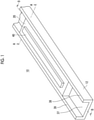
- Fig. 1 is a schematic perspective view of a gas pressure actuator 10 related to one embodiment of the invention.
- the gas pressure actuator 10 is constituted of a guide 12 that extends in one direction and formed to have a recessed cross-section, and a slider 20 that is movable in an axial direction along the guide 12 while being guided by the guide 12 and has a rectangular parallelepiped shape.
- the guide 12 has a bottom wall 37, a first side wall 38, and a second side wall 39, and both ends and an intermediate part of the bottom wall 37 are supported by legs that are not illustrated.
- the slider 20 has a lid 40.
- the lid 40 closes an opening of an air servo chamber 28 (to be described below) formed in the slider 20.
- the lid 40 becomes unnecessary in a case where the air servo chamber 28 is formed so as not to pass through the slider 20.
- the slider 20 is housed so as to have a slight gap inside a recessed guide 12. As will be described below in detail, the slider 20 is smoothly movable along the guide 12 by ejecting compression gas (for example, air) from an air pad provided in the slider 20.
- compression gas for example, air
- the gas pressure actuator 10 is used for driving a movable stage, for example in a device that operates within a vacuum chamber of an electron beam exposure system or the like.
- the gas pressure actuator is used together with the electron beam exposure system, there is a concern that an electron beam trajectory is affected when the gas pressure actuator is a magnetic body. Therefore, the guide 12, the legs, and the slider 20 are formed of, a non-magnetic-material material, for example, ceramics.
- the gas pressure actuator 10 Since the gas pressure actuator 10 has no generation of microscopic dust from lubricating oil or a sliding surface, for example, as compared to a slider in which a rolling bearing or a linear guide is used, the gas pressure actuator 10 is suitable for, for example, an electron beam exposure system used in a vacuum environment.
- Fig. 2 is a perspective view of the slider 20 as seen from below
- Fig. 3 is an axial sectional view of the gas pressure actuator 10 taken along line A-A in Figs. 1 and 2
- a plurality of air pads 30 are formed on surfaces, which face the recessed guide 12, among surfaces of the slider 20 that constitute the substantially rectangular parallelepiped shape, that is, a bottom surface 22, a first side surface 24, and a second side surface 26.
- the air pads 30 eject a high-pressure gas supplied from an air supply system (not shown), and form a high-pressure gas layer in a minute gap between the air pads 30 and the guide 12, thereby floating the slider 20 from the guide 12.
- the air servo chamber 28 for driving the slider 20 is formed at a central part of the slider 20.
- Exhaust grooves 32, 34, and 36 for differential exhaust are formed at edge portions of the bottom surface 22, the first side surface 24, and the second side surface 26 of the slider 20 so as to surround the plurality of air pads 30.
- the exhaust grooves 32, 34, and 36 all include a portion that extends in an axial direction of the slider 20.
- the exhaust groove 32 is open to the atmosphere.
- the exhaust groove 32 may be connected to an exhaust pump (not illustrated).
- the exhaust grooves 34 and 36 are connected to the exhaust pump (not illustrated) for setting the pressure in the exhaust grooves to a low vacuum-pressure level and a middle vacuum-pressure level, respectively, and exhaust a compression gas, which is supplied from the air pads 30 and the air servo chamber 28 of the slider 20 to an internal space, to the outside.
- the gas pressure actuator can be made available even in a vacuum environment by preventing the compression gas from leaking out from a gap between the guide 12 and the slider 20.
- the gas pressure actuator 10 is available in an atmospheric pressure environment, it is not necessary to provide such exhaust grooves 32, 34, and 36.
- the guide 12 in a case where the guide 12 is made to have a recessed shape, the guide 12 is likely to be deformed such that the spacing between an upper end of the first side wall 38 and an upper end of the second side wall 39 increases depending on the load capability of the air pads 30 disposed on the side surfaces of the slider 20 (that is, such that an upper side thereof widens) . Accordingly, there is a concern that it may be impossible to secure desired bearing rigidity. Thus, it is preferable that the air pads 30 of the side surfaces of the slider 20 are disposed as close to the bottom surface 22 side as possible.
- Fig. 4 is a sectional view of the gas pressure actuator, taken along line B-B in Fig. 1 , illustrating an operation principle of the gas pressure actuator 10.
- the gap between the guide 12 and the slider 20 and a gap between a partition wall 13 and the air servo chamber 28 are drawn in an exaggerated manner. In practice, for example, these gaps are about several microns.
- the partition wall 13 that partitions the air servo chamber 28 of the slider 20 into two servo chambers 28A and 28B with respect to the axial direction is fixed to the guide 12.
- the air supply systems 17A and 17B for enabling compression gas to enter and leave the respective servo chambers are connected to the two servo chambers 28A and 28B, respectively.
- the air supply systems 17A and 17B include servo valves 16A and 16B and compression gas supply sources 18A and 18B, respectively.
- the slider 20 floats slightly with respect to the guide 12.
- the partition wall 13 acts as a piston and the slider 20 move leftward in the drawing. In this way, the slider 20 can be moved to an arbitrary position with respect to the guide 12 by controlling the opening degrees of the servo valves 16A and 16B.
- a structure in which the substantially rectangular parallelepiped-shaped slider slides inside the guide having the recessed cross-section is adopted instead of a slider that restrains four surfaces of the guide.
- the slider since it is possible to support the guide not only at those both ends but in a plurality of places, it is easy to secure the deflection rigidity of the guide, and the cross-sectional area of the guide can be made small as compared to a guide shaft having a square cross-section. Hence, reduction in size of the guide and cost reduction are realized.
- the slider can be made to have a flat structure, the installation height of the gas pressure actuator can be suppressed.
- assembly and adjustment of the slider with respect to the guide can be simplified.
- the slider and the guide can be manufactured as an integral structure, respectively, the number of parts can be reduced.
- Fig. 5 is an axial sectional view of a gas pressure actuator 10' related to such a modification example. Since members appearing in Fig. 3 among members denoted by reference signs in Fig. 5 have the same configuration, the description thereof will be omitted.
- the magnet preloading mechanism 48 applies a downward force to the slider 20 with an attractive force from a magnet.
- the slider 20 is provided with an L-shaped supporting member 42 that extends toward both side walls of the guide 12 from an upper surface of the slider 20.
- a magnet 44 is installed on a lower surface of the supporting member 42 and a soft magnetic material 46 is installed on an upper part of the first side wall 38 and an upper part of the second side wall 39 in the guide 12 so as to attract each other.
- the gas pressure actuator 10 In a case where the gas pressure actuator 10 is used with the electron beam exposure system, there is a concern that a leaked magnetic field from the magnet 44 may affect the electron beam trajectory. Thus, it is preferable to perform magnetic shielding to the peripheries of the magnet 44 and the soft magnetic material 46 (places illustrated by dotted lines C in Fig. 5 ) to suppress the leaked magnetic field.
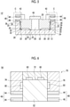
- Fig. 6 is an axial sectional view of a gas pressure actuator 50 related to such a modification example.
- a guide 52 has a square cross-section and a slider 70 has a recessed cross-section.
- a plurality of air pads 80 are formed on surfaces, which face the guide 52, among inner surfaces of the slider 70, that is, an upper surface 72, a side surface 74, and a side surface 76.
- the air pads 80 eject a high-pressure gas supplied from the air supply system (not shown), and form a high-pressure gas layer in a minute gap between the air pads 80 and the guide 52, thereby floating the slider 70 from the guide 52.
- An air servo chamber (not illustrated) for driving the slider 70 is formed at a central part of the slider 70.
- exhaust grooves for differential exhaust are formed at edge portions of the upper surface 72, the side surface 74, and the side surface 76 of the slider 70 so as to surround the plurality of air pads 80.
- the exhaust grooves are connected to the exhaust pump (not illustrated), and exhaust compression gas, which is supplied from the air pads 80 and the air servo chamber of the slider 70 to the internal space, to the outside. Accordingly, the gas pressure actuator can be made available even in a vacuum environment by preventing the compression gas from leaking out from a gap between the guide 52 and the slider 70. In addition, in a case where the gas pressure actuator 50 is available in an atmospheric pressure environment, it is not necessary to provide such exhaust grooves.
- a linear guide or the like may be used to structurally connect the slider and the guide together in the upward-downward direction. In this case, it becomes unnecessary to provide the slider with the air pads. Additionally, even in a case where the linear guide is used, the actuator can be used in both the atmospheric pressure environment and the vacuum environment.
- the air pads, the air pads, and the magnet preloading mechanism, and the linear guide can be freely selected. Additionally, it is possible to use the actuator in both the atmospheric pressure environment and the vacuum environment.
- the gas pressure actuator is made of a non-magnetic material, particularly, ceramics
- the invention is also applicable to a gas pressure actuator made of a magnetic substance.
- the invention is applicable also to an actuator including a guide and a slider having an arbitrary cross-sectional shape.
- Figs. 7 to 9 are axial sectional views of gas pressure actuators related to such modification examples, respectively. Each of Figs. 7 to 9 corresponds to Fig. 3 .
- Fig. 7 is an axial sectional view of a gas pressure actuator 110 related to a modification example.
- the gas pressure actuator 110 includes the guide 12 and the slider 20.
- the slider 20 has a trapezoidal cross-sectional shape, and the first side surface 24 and the second side surface 26 are inclined so as to be closer to each other as they move upward.
- the guide 12 has a recessed cross-section corresponding to the slider 20. That is, the guide 12 is inclined such that an inner surface 38a of the first side wall 38 and an inner surface 39a of the second side wall 39 are closer to each other as they move upward.
- the same effects as the effects exhibited by the gas pressure actuator related to the embodiment are exhibited.
- the first side surface 24 and the second side surface 26 of the slider 20 are inclined, and the surfaces of the guide 12 that faces these side surfaces are inclined similarly.
- the first side surface 24 and the second side surface 26 can receive the downward force from the high-pressure gas layer formed in the gap between the air pad 30 and the guide 12 by the gas ejected from the air pads 30. That is, according to the present modification example, the bearing rigidity of the gas pressure actuator is enhanced.
- Fig. 8 is an axial sectional view of a gas pressure actuator 210 related to a modification example.
- the gas pressure actuator 210 includes the guide 12 and the slider 20.
- the slider 20 has an oblong cross-sectional shape, and the guide 12 has a recessed cross-sectional shape.
- the first side wall 38 and the second side wall 39 of the guide 12 have an L-shaped cross-section.
- the first side wall 38 and the second side wall 39 each have a first extending part 38b and a second extending part 39b that extend toward each other.
- the guide 12 has an upper wall in addition to the bottom wall 37, the first side wall 38, and the second side wall 39 and a portion of the upper wall (central part) is open.
- the air pads 30 are formed at portions, which face the first extending part 38b and the second extending part 39b, on the upper surface of the slider 20.
- the same effects as the effects exhibited by the gas pressure actuator related to the embodiment are exhibited.
- the air pads 30 are formed on the upper surface of the slider 20 which faces the first extending part 38b and the second extending part 39b.
- the slider 20 can receive the downward force from the high-pressure gas layer formed in the gap between the air pads 30 and the guide 12 by the gas ejected from the air pads 30. That is, according to the present modification example, the bearing rigidity of the gas pressure actuator is enhanced.
- Fig. 9 is an axial sectional view of a gas pressure actuator 310 related to a modification example not part of the invention.
- the gas pressure actuator 310 includes the guide 12 and the slider 20.
- the guide 12 and the slider 20 have a rectangular cross-sectional shape.
- the guide 12 and the slider 20 may have a polygonal cross-sectional shape, not limited to the rectangular cross-sectional shape.
- the three surfaces of the guide 12 are open.
- a plurality of air pads 30 are formed on a surface, which faces the guide 12, among surfaces constituting the slider 20, that is, the bottom surface 22. Additionally, the exhaust grooves 32, 34, and 36 for differential exhaust are formed on the bottom surface 22 of the slider 20 so as to surround the plurality of air pads 30.
- Fig. 10 is an axial sectional view of a gas pressure actuator 420 related to the invention.
- Fig. 10 corresponds to Fig. 8 .
- modification air servo chambers 28 are formed in the first side surface 24 and the second side surface 26, respectively. That is, the two air servo chambers 28 are formed so as to face the inner surface 38a and the inner surface 39a that face each other with the slider 20 interposed therebetween.
- the actuator in which the slider is movable while being guided by the guide can be made to have a simple structure.
Landscapes
- Engineering & Computer Science (AREA)
- General Engineering & Computer Science (AREA)
- Mechanical Engineering (AREA)
- Physics & Mathematics (AREA)
- Fluid Mechanics (AREA)
- Chemical & Material Sciences (AREA)
- Analytical Chemistry (AREA)
- Magnetic Bearings And Hydrostatic Bearings (AREA)
- Actuator (AREA)
- Bearings For Parts Moving Linearly (AREA)
- Support Of The Bearing (AREA)
Description
- The present invention relates to an actuator in which a slider is movable while being guided by a guide.
- Actuators used in a vacuum environment are required not to contaminate the inside of a vacuum chamber. A gas pressure actuator is known as such an actuator (for example, PTL 1). The gas pressure actuator is configured such that the slider can be moved smoothly with respect to a guide shaft by ejecting compression gas from air pad provided within the slider. The gas pressure actuator has various advantages, such as no generation of microscopic dust from lubricating oil or a sliding surface and no generation of heat from the actuator, like actuators using a rolling bearing and a linear guide.
US 6 328 473 B1 discloses an actuator according to the preambles of claims 1, 4 and 7. -
- [PTL 1]:
Japanese Patent No. 4443778 - [PTL2]:
US 6 328 473 B1 Summary of Invention Technical Problem - In the related-art known gas pressure actuator, a slider formed in an oblong tubular shape has a structure in which a guide shaft similarly having a rectangular cross-section is restrained by four surfaces. In the actuator having such a structure several manufacturing problems such that the manufacturing cost of the guide shaft is high and the assembly and adjustment of the slider with respect to the guide shaft is complicated are present.
- The invention has been made in view of such a situation, and an object thereof is to provide a simple structure of an actuator in which a slider is movable while being guided by a guide.
- An actuator according to the invention is disclosed in claims 1, 4 and 7.
- The expression "one surface is open" includes a case where one entire surface is open and also a case where a portion of one surface is open.
- The guide has according to the invention a recessed cross-section, and the slider is configured to be floated with respect to the guide and guided by the guide while being restrained by three surfaces that constitute the recessed cross-section.
- The guide may have a polygonal cross-section, and the slider may be configured to be floated with respect to the guide and guided by the guide while being restrained by one surface of a plurality of surfaces that constitute the polygonal cross-section.
- According to these aspects, since the slider has a structure in which one surface of the guide is open compared to the actuator of the related-art structure in which the guide shaft is restrained by the four surfaces, the structure of the guide and the slider can be simplified.
- A magnet preloading mechanism that applies a downward force resulting from magnetism to the slider may be provided between the slider and the guide. According to this, the bearing rigidity of the actuator can be secured.
- Additionally, another aspect of the invention is also an actuator. This actuator is an actuator including a guide that extends in one direction; and a slider that is movable in an axial direction with respect to the guide. At least one surface of the guide is open. The slider has an air pad that ejects compression gas, and an exhaust groove that discharges the compressed air ejected from the air pad, and is configured so as to be floated with respect to the guide and guided by the guide. The exhaust groove includes a portion that extends in the axial direction.
- The guide has according to the invention a recessed cross-section, and the slider is configured to be floated with respect to the guide and guided by the guide while being restrained by three surfaces that constitute the recessed cross-section.
- The guide may have a polygonal cross-section, and the slider may be configured to be floated with respect to the guide and guided by the guide while being restrained by one surface of a plurality of surfaces that constitute the polygonal cross-section.
- According to these aspects, since the slider has a structure in which the surfaces of the guide are open compared to the actuator of the related-art structure in which the guide shaft is restrained by the four surfaces, the structure of the guide and the slider can be simplified.
- A magnet preloading mechanism that applies a downward force resulting from magnetism to the slider may be provided between the slider and the guide. According to this, the bearing rigidity of the actuator can be secured.
- Additionally, still another aspect of the invention is also an actuator. The actuator includes a guide that extends in one direction; and a slider that is movable in an axial direction with respect to the guide. Either the guide or the slider has a recessed cross-section, and the slider is guided by the guide while the other of the guide and the slider is restrained by three surfaces that constitute the recessed cross-section.
- According to the aspect, since the slider has a structure in which one surface of the guide or the slider is open compared to the actuator of the related-art structure in which the guide shaft is restrained by the four surfaces, the structure of the guide and the slider can be simplified.
- The slider has according to the invention an air pad that ejects compression gas, and is configured to be floated with respect to the guide and guided by the guide. According to this, even in the case of the gas pressure actuator, the structure of the guide and the slider can be simplified.
- The slider has according to the invention an exhaust groove that discharges the compressed air ejected from the air pad and the exhaust groove includes a portion that extends in the axial direction. According to this, the gas pressure actuator of the structure in which one surface of the guide or the slider is open can be used even in a vacuum environment.
- The slider has according to the invention an air servo chamber that extends in the axial direction. The guide has a partition wall that enters the air servo chamber to partition the air servo chamber into two. The slider supplies the compression gas to one partition of the two partitions of the air servo chamber and discharges the compression gas from the other partition, thereby moving in the axial direction with respect to the guide.
- A magnet preloading mechanism that applies a downward force resulting from magnetism to the slider may be provided between the slider and the guide. According to this, the bearing rigidity of the actuator can be secured.
- According to the invention, the actuator in which the slider is movable while being guided by the guide can be made to have a simple structure.
-
-
Fig. 1 is a schematic perspective view of a gas pressure actuator related to one embodiment of the invention. -
Fig. 2 is a perspective view of a slider that constitutes the gas pressure actuator of the invention. -
Fig. 3 is an axial sectional view of the gas pressure actuator taken along line A-A inFigs. 1 and2 . -
Fig. 4 is a sectional view of the gas pressure actuator, taken along line B-B inFig. 1 , illustrating an operation principle of the gas pressure actuator. -
Fig. 5 is an axial sectional view of a gas pressure actuator related to a modification example of the invention. -
Fig. 6 is an axial sectional view of a gas pressure actuator related to another modification example of the invention. -
Fig. 7 is an axial sectional view of a gas pressure actuator related to still another modification example of the invention. -
Fig. 8 is an axial sectional view of a gas pressure actuator related to still another modification example of the invention. -
Fig. 9 is an axial sectional view of a gas pressure actuator related to still another modification example not part of the invention. -
Fig. 10 is an axial sectional view of a gas pressure actuator related to still another modification example of the invention - Hereinafter, the same or equivalent constituent elements or members illustrated in the respective drawings will be denoted by the same reference signs, and redundant description will be appropriately omitted. Additionally, the dimensions of the members in the respective drawings are appropriately enlarged and reduced in order to make the invention easily understood. Additionally, in the respective drawings, some of the members that are not important in explaining the embodiment will be omitted and illustrated.
-
Fig. 1 is a schematic perspective view of agas pressure actuator 10 related to one embodiment of the invention. Thegas pressure actuator 10 is constituted of aguide 12 that extends in one direction and formed to have a recessed cross-section, and aslider 20 that is movable in an axial direction along theguide 12 while being guided by theguide 12 and has a rectangular parallelepiped shape. Theguide 12 has abottom wall 37, afirst side wall 38, and asecond side wall 39, and both ends and an intermediate part of thebottom wall 37 are supported by legs that are not illustrated. - The
slider 20 has alid 40. Thelid 40 closes an opening of an air servo chamber 28 (to be described below) formed in theslider 20. In addition, thelid 40 becomes unnecessary in a case where theair servo chamber 28 is formed so as not to pass through theslider 20. Theslider 20 is housed so as to have a slight gap inside a recessedguide 12. As will be described below in detail, theslider 20 is smoothly movable along theguide 12 by ejecting compression gas (for example, air) from an air pad provided in theslider 20. - The
gas pressure actuator 10 is used for driving a movable stage, for example in a device that operates within a vacuum chamber of an electron beam exposure system or the like. In a case where the gas pressure actuator is used together with the electron beam exposure system, there is a concern that an electron beam trajectory is affected when the gas pressure actuator is a magnetic body. Therefore, theguide 12, the legs, and theslider 20 are formed of, a non-magnetic-material material, for example, ceramics. - Since the
gas pressure actuator 10 has no generation of microscopic dust from lubricating oil or a sliding surface, for example, as compared to a slider in which a rolling bearing or a linear guide is used, thegas pressure actuator 10 is suitable for, for example, an electron beam exposure system used in a vacuum environment. -
Fig. 2 is a perspective view of theslider 20 as seen from below, andFig. 3 is an axial sectional view of thegas pressure actuator 10 taken along line A-A inFigs. 1 and2 . A plurality ofair pads 30 are formed on surfaces, which face the recessedguide 12, among surfaces of theslider 20 that constitute the substantially rectangular parallelepiped shape, that is, abottom surface 22, afirst side surface 24, and asecond side surface 26. Theair pads 30 eject a high-pressure gas supplied from an air supply system (not shown), and form a high-pressure gas layer in a minute gap between theair pads 30 and theguide 12, thereby floating theslider 20 from theguide 12. Theair servo chamber 28 for driving theslider 20 is formed at a central part of theslider 20. -
Exhaust grooves bottom surface 22, thefirst side surface 24, and thesecond side surface 26 of theslider 20 so as to surround the plurality ofair pads 30. Hence, theexhaust grooves slider 20. Theexhaust groove 32 is open to the atmosphere. In addition, theexhaust groove 32 may be connected to an exhaust pump (not illustrated). Theexhaust grooves air pads 30 and theair servo chamber 28 of theslider 20 to an internal space, to the outside. Accordingly, the gas pressure actuator can be made available even in a vacuum environment by preventing the compression gas from leaking out from a gap between theguide 12 and theslider 20. In addition, in a case where thegas pressure actuator 10 is available in an atmospheric pressure environment, it is not necessary to providesuch exhaust grooves - in a case where the
guide 12 is made to have a recessed shape, theguide 12 is likely to be deformed such that the spacing between an upper end of thefirst side wall 38 and an upper end of thesecond side wall 39 increases depending on the load capability of theair pads 30 disposed on the side surfaces of the slider 20 (that is, such that an upper side thereof widens) . Accordingly, there is a concern that it may be impossible to secure desired bearing rigidity. Thus, it is preferable that theair pads 30 of the side surfaces of theslider 20 are disposed as close to thebottom surface 22 side as possible. -
Fig. 4 is a sectional view of the gas pressure actuator, taken along line B-B inFig. 1 , illustrating an operation principle of thegas pressure actuator 10. In addition, inFig. 4 , the gap between theguide 12 and theslider 20 and a gap between apartition wall 13 and theair servo chamber 28 are drawn in an exaggerated manner. In practice, for example, these gaps are about several microns. As illustrated in the drawings, thepartition wall 13 that partitions theair servo chamber 28 of theslider 20 into twoservo chambers guide 12. Theair supply systems servo chambers air supply systems servo valves gas supply sources - If compressed air is supplied to the
air pads 30, theslider 20 floats slightly with respect to theguide 12. Here, for example, if the compressed air is supplied to theservo chamber 28A and the compressed air is discharged from theservo chamber 28B, thepartition wall 13 acts as a piston and theslider 20 move leftward in the drawing. In this way, theslider 20 can be moved to an arbitrary position with respect to theguide 12 by controlling the opening degrees of theservo valves - As described above, according to the present embodiment, a structure in which the substantially rectangular parallelepiped-shaped slider slides inside the guide having the recessed cross-section is adopted instead of a slider that restrains four surfaces of the guide. In this structure, since it is possible to support the guide not only at those both ends but in a plurality of places, it is easy to secure the deflection rigidity of the guide, and the cross-sectional area of the guide can be made small as compared to a guide shaft having a square cross-section. Hence, reduction in size of the guide and cost reduction are realized. Additionally, since the slider can be made to have a flat structure, the installation height of the gas pressure actuator can be suppressed. Additionally, since it is not necessary to form the slider in a tubular shape, assembly and adjustment of the slider with respect to the guide can be simplified. Moreover, since the slider and the guide can be manufactured as an integral structure, respectively, the number of parts can be reduced.
- In order to strengthen the bearing rigidity of the gas pressure actuator, a magnet preloading mechanism may be provided.
Fig. 5 is an axial sectional view of a gas pressure actuator 10' related to such a modification example. Since members appearing inFig. 3 among members denoted by reference signs inFig. 5 have the same configuration, the description thereof will be omitted. - The
magnet preloading mechanism 48 applies a downward force to theslider 20 with an attractive force from a magnet. Theslider 20 is provided with an L-shaped supportingmember 42 that extends toward both side walls of theguide 12 from an upper surface of theslider 20. Amagnet 44 is installed on a lower surface of the supportingmember 42 and a softmagnetic material 46 is installed on an upper part of thefirst side wall 38 and an upper part of thesecond side wall 39 in theguide 12 so as to attract each other. By configuring the invention in this way, the bearing rigidity of the gas pressure actuator can be enhanced. - In a case where the
gas pressure actuator 10 is used with the electron beam exposure system, there is a concern that a leaked magnetic field from themagnet 44 may affect the electron beam trajectory. Thus, it is preferable to perform magnetic shielding to the peripheries of themagnet 44 and the soft magnetic material 46 (places illustrated by dotted lines C inFig. 5 ) to suppress the leaked magnetic field. - Although a case where the
guide 12 has the recessed cross-section and theslider 20 has the substantially rectangular parallelepiped shape has been described above, the shapes of both may be replaced.Fig. 6 is an axial sectional view of agas pressure actuator 50 related to such a modification example. - In
Fig. 6 , aguide 52 has a square cross-section and aslider 70 has a recessed cross-section. A plurality ofair pads 80 are formed on surfaces, which face theguide 52, among inner surfaces of theslider 70, that is, anupper surface 72, aside surface 74, and aside surface 76. Theair pads 80 eject a high-pressure gas supplied from the air supply system (not shown), and form a high-pressure gas layer in a minute gap between theair pads 80 and theguide 52, thereby floating theslider 70 from theguide 52. An air servo chamber (not illustrated) for driving theslider 70 is formed at a central part of theslider 70. - Although not illustrated, exhaust grooves for differential exhaust are formed at edge portions of the
upper surface 72, theside surface 74, and theside surface 76 of theslider 70 so as to surround the plurality ofair pads 80. The exhaust grooves are connected to the exhaust pump (not illustrated), and exhaust compression gas, which is supplied from theair pads 80 and the air servo chamber of theslider 70 to the internal space, to the outside. Accordingly, the gas pressure actuator can be made available even in a vacuum environment by preventing the compression gas from leaking out from a gap between theguide 52 and theslider 70. In addition, in a case where thegas pressure actuator 50 is available in an atmospheric pressure environment, it is not necessary to provide such exhaust grooves. - A case where the
magnet preloading mechanism 48 is provided in order to strengthen the bearing rigidity of the actuator has been described in the above embodiment. However, instead of the magnet preloading mechanism, a linear guide or the like may be used to structurally connect the slider and the guide together in the upward-downward direction. In this case, it becomes unnecessary to provide the slider with the air pads. Additionally, even in a case where the linear guide is used, the actuator can be used in both the atmospheric pressure environment and the vacuum environment. - The configuration of the actuator related to some embodiments have been described above. It is to be understood by those skilled in the art that this embodiment is exemplary, that various modification examples are possible for combinations of the respective constituent elements, and that such modification examples are also within the scope of the invention.
- According to the invention, as a guide mechanism of the actuator, the air pads, the air pads, and the magnet preloading mechanism, and the linear guide can be freely selected. Additionally, it is possible to use the actuator in both the atmospheric pressure environment and the vacuum environment.
- Although a case where the gas pressure actuator is made of a non-magnetic material, particularly, ceramics has been described in the embodiment, the invention is also applicable to a gas pressure actuator made of a magnetic substance.
- Although a case where the guide and the slider of the actuator have the oblong cross-sectional shape has been described in the embodiment, the invention is applicable also to an actuator including a guide and a slider having an arbitrary cross-sectional shape.
-
Figs. 7 to 9 are axial sectional views of gas pressure actuators related to such modification examples, respectively. Each ofFigs. 7 to 9 corresponds toFig. 3 . -
Fig. 7 is an axial sectional view of agas pressure actuator 110 related to a modification example. Thegas pressure actuator 110 includes theguide 12 and theslider 20. Theslider 20 has a trapezoidal cross-sectional shape, and thefirst side surface 24 and thesecond side surface 26 are inclined so as to be closer to each other as they move upward. Theguide 12 has a recessed cross-section corresponding to theslider 20. That is, theguide 12 is inclined such that an inner surface 38a of thefirst side wall 38 and aninner surface 39a of thesecond side wall 39 are closer to each other as they move upward. - According to the present modification example, the same effects as the effects exhibited by the gas pressure actuator related to the embodiment are exhibited. In addition, in the present modification example, the
first side surface 24 and thesecond side surface 26 of theslider 20 are inclined, and the surfaces of theguide 12 that faces these side surfaces are inclined similarly. Hence, thefirst side surface 24 and the second side surface 26 (eventually, the slider 20) can receive the downward force from the high-pressure gas layer formed in the gap between theair pad 30 and theguide 12 by the gas ejected from theair pads 30. That is, according to the present modification example, the bearing rigidity of the gas pressure actuator is enhanced. -
Fig. 8 is an axial sectional view of agas pressure actuator 210 related to a modification example. Thegas pressure actuator 210 includes theguide 12 and theslider 20. Theslider 20 has an oblong cross-sectional shape, and theguide 12 has a recessed cross-sectional shape. - In the present modification example, the
first side wall 38 and thesecond side wall 39 of theguide 12 have an L-shaped cross-section. Thefirst side wall 38 and thesecond side wall 39 each have a first extendingpart 38b and a second extendingpart 39b that extend toward each other. In other words, it can be said that theguide 12 has an upper wall in addition to thebottom wall 37, thefirst side wall 38, and thesecond side wall 39 and a portion of the upper wall (central part) is open. Theair pads 30 are formed at portions, which face the first extendingpart 38b and the second extendingpart 39b, on the upper surface of theslider 20. - According to the present modification example, the same effects as the effects exhibited by the gas pressure actuator related to the embodiment are exhibited. In addition, in the present modification example, the
air pads 30 are formed on the upper surface of theslider 20 which faces the first extendingpart 38b and the second extendingpart 39b. Hence, theslider 20 can receive the downward force from the high-pressure gas layer formed in the gap between theair pads 30 and theguide 12 by the gas ejected from theair pads 30. That is, according to the present modification example, the bearing rigidity of the gas pressure actuator is enhanced. -
Fig. 9 is an axial sectional view of agas pressure actuator 310 related to a modification example not part of the invention. Thegas pressure actuator 310 includes theguide 12 and theslider 20. Theguide 12 and theslider 20 have a rectangular cross-sectional shape. In addition, theguide 12 and theslider 20 may have a polygonal cross-sectional shape, not limited to the rectangular cross-sectional shape. In the present modification example, the three surfaces of theguide 12 are open. - A plurality of
air pads 30 are formed on a surface, which faces theguide 12, among surfaces constituting theslider 20, that is, thebottom surface 22. Additionally, theexhaust grooves bottom surface 22 of theslider 20 so as to surround the plurality ofair pads 30. - According to the present modification example, since only the
bottom surface 22 of theslider 20 is restrained, the structure of theguide 12 and theslider 20 is further simplified. - Although a case where the
slider 20 is formed with oneair servo chamber 28 has been described in the embodiment, a plurality of air servo chambers are formed according to the invention.Fig. 10 is an axial sectional view of a gas pressure actuator 420 related to the invention.Fig. 10 corresponds toFig. 8 . In the present invention, modificationair servo chambers 28 are formed in thefirst side surface 24 and thesecond side surface 26, respectively. That is, the twoair servo chambers 28 are formed so as to face the inner surface 38a and theinner surface 39a that face each other with theslider 20 interposed therebetween. According to the present invention, even if pressure fluctuation occurs in the twoair servo chambers 28, a force caused by the pressure fluctuation is offset by the twoair servo chambers 28. For that reason, even if pressure fluctuation occurs in theair servo chamber 28, the pressure fluctuation can be kept from influencing between theslider 20 and theguide 12. -
- 10:
- GAS PRESSURE ACTUATOR
- 12:
- GUIDE
- 20:
- SLIDER
- 30:
- AIR PAD
- 34:
- EXHAUST GROOVE
- 44:
- MAGNET
- 48:
- MAGNET RELOADING MECHANISM
- 50:
- GAS PRESSURE ACTUATOR
- 52:
- GUIDE
- 70:
- SLIDER
- 80:
- AIR PAD.
- According to the invention, the actuator in which the slider is movable while being guided by the guide can be made to have a simple structure.
Claims (10)
- An actuator comprising:a guide (12) that extends in one direction; anda slider (20) that is movable in an axial direction with respect to the guide,wherein at least one part of one surface of the guide is open,wherein the slider (20) has an air pad (30) that ejects compression gas, and at least two air servo chambers (28) for driving the slider, and is configured so as to be floated with respect to the guide and guided by the guide,characterised in that
the two air servo chambers are formed so as to face an inner surface (38a) and another inner surface (39a) of the guide (12) that face each other with the slider (20) interposed therebetween. - The actuator according to Claim 1,
wherein the guide has a recessed cross-section, and the slider is configured to be floated with respect to the guide and guided by the guide while being restrained by three surfaces that constitute the recessed cross-section. - The actuator according to Claim 1,
wherein the guide has a polygonal cross-section, and the slider is configured to be floated with respect to the guide and guided by the guide while being restrained by one surface of a plurality of surfaces that constitute the polygonal cross-section. - An actuator comprising:a guide that extends in one direction; anda slider that is movable in an axial direction with respect to the guide,wherein at least one part of one surface of the guide is open,wherein the slider has an air pad that ejects compression gas, at least two air servo chambers for driving the slider, and an exhaust groove that discharges the compressed air ejected from the air pad, and is configured so as to be floated with respect to the guide and guided by the guide,wherein the exhaust groove includes a portion that extends in the axial direction,characterised in thatthe two air servo chambers are formed so as to face an inner surface and another inner surface of the guide (12)that face each other with the slider interposed therebetween.
- The actuator according to Claim 4,
wherein the guide has a recessed cross-section, and the slider is configured to be floated with respect to the guide and guided by the guide while being restrained by three surfaces that constitute the recessed cross-section. - The actuator according to Claim 4,
wherein the guide has a polygonal cross-section, and the slider is configured to be floated with respect to the guide and guided by the guide while being restrained by one surface of a plurality of surfaces that constitute the polygonal cross-section. - An actuator comprising:a guide that extends in one direction; anda slider that is movable in an axial direction with respect to the guide,wherein either the guide or the slider has a recessed cross-section, and the slider is guided by the guide while the other of the guide and the slider is restrained by three surfaces that constitute the recessed cross-section, wherein the slider has at least two air servo chambers for driving the slider,characterised in that
the two air servo chambers are formed so as to face 20 an inner surface and another inner surface of the guide (12) that face each other with the slider interposed therebetween. - The actuator according to Claim 7,
wherein the slider has an air pad that ejects compression gas, and is configured to be floated with respect to the guide and guided by the guide. - The actuator according to Claim 8,wherein the slider further has an exhaust groove that discharges the compressed air ejected from the air pad, andwherein the exhaust groove includes a portion that extends in the axial direction.
- The actuator according to any one of Claims 7 to 9, wherein the slider has an air servo chamber that extends in the axial direction,wherein the guide has a partition wall that enters the air servo chamber to partition the air servo chamber into two, andwherein the slider supplies the compression gas to one partition of the two partitions of the air servo chamber and discharges the compression gas from the other partition, thereby moving in the axial direction with respect to the guide.
Applications Claiming Priority (2)
| Application Number | Priority Date | Filing Date | Title |
|---|---|---|---|
| JP2015072054 | 2015-03-31 | ||
| PCT/JP2016/057070 WO2016158229A1 (en) | 2015-03-31 | 2016-03-08 | Actuator |
Publications (3)
| Publication Number | Publication Date |
|---|---|
| EP3279486A1 EP3279486A1 (en) | 2018-02-07 |
| EP3279486A4 EP3279486A4 (en) | 2018-12-05 |
| EP3279486B1 true EP3279486B1 (en) | 2022-02-23 |
Family
ID=57004162
Family Applications (1)
| Application Number | Title | Priority Date | Filing Date |
|---|---|---|---|
| EP16772113.3A Active EP3279486B1 (en) | 2015-03-31 | 2016-03-08 | Actuator |
Country Status (7)
| Country | Link |
|---|---|
| US (1) | US10371279B2 (en) |
| EP (1) | EP3279486B1 (en) |
| JP (2) | JP6893170B2 (en) |
| KR (1) | KR102415241B1 (en) |
| CN (2) | CN107429738A (en) |
| TW (1) | TWI589802B (en) |
| WO (1) | WO2016158229A1 (en) |
Families Citing this family (4)
| Publication number | Priority date | Publication date | Assignee | Title |
|---|---|---|---|---|
| JP6696821B2 (en) * | 2016-04-26 | 2020-05-20 | Dmg森精機株式会社 | Machine Tools |
| JP6704658B2 (en) * | 2016-10-13 | 2020-06-03 | 住友重機械工業株式会社 | Stage equipment |
| JP7539822B2 (en) * | 2020-12-07 | 2024-08-26 | 住友重機械工業株式会社 | Method and device for controlling pneumatic actuator |
| JP2023124519A (en) | 2022-02-25 | 2023-09-06 | 住友重機械工業株式会社 | Actuator, stage device, exposure device, and inspection device |
Citations (3)
| Publication number | Priority date | Publication date | Assignee | Title |
|---|---|---|---|---|
| JPH11190306A (en) * | 1997-12-25 | 1999-07-13 | Ntn Corp | Air slide device |
| US6328473B1 (en) * | 1998-06-17 | 2001-12-11 | Nikon Corporation | Static air-bearing and stage apparatus using the bearing and optical apparatus using the stage apparatus |
| WO2004032212A1 (en) * | 2002-10-04 | 2004-04-15 | Nikon Corporation | Stage device and exposure device |
Family Cites Families (20)
| Publication number | Priority date | Publication date | Assignee | Title |
|---|---|---|---|---|
| JPS6237514A (en) * | 1985-08-10 | 1987-02-18 | Omron Tateisi Electronics Co | Static pressure bearing device |
| JPH0518498Y2 (en) * | 1987-09-09 | 1993-05-17 | ||
| JPH0429616A (en) * | 1990-05-24 | 1992-01-31 | Nagase Iron Works Co Ltd | Fluid passage device |
| IL131647A0 (en) * | 1999-08-30 | 2001-01-28 | Leonid Kashchenevsky | Method and device to control the accuracy of movement of a unit moving linearly on hydro- or aerostatic slides |
| JP2001173654A (en) | 1999-12-15 | 2001-06-26 | Nikon Corp | Hydrostatic bearing device and optical device using it |
| WO2001057409A1 (en) * | 2000-02-01 | 2001-08-09 | Toto Ltd. | Hydrostatic gas bearing, hydrostatic gas bearing device for use in vacuum environment, and gas recovering method for the hydrostatic gas bearing device |
| JP2002170765A (en) * | 2000-12-04 | 2002-06-14 | Nikon Corp | Stage system and exposure system |
| JP4443778B2 (en) | 2001-02-07 | 2010-03-31 | 住友重機械工業株式会社 | Fluid pressure actuator |
| JP2002252166A (en) * | 2001-02-27 | 2002-09-06 | Canon Inc | Stage device, aligner, device manufacturing method and movement guide method |
| JP2002257138A (en) * | 2001-02-28 | 2002-09-11 | Canon Inc | Static pressure fluid bearing device, stage device using the same, exposure device, and manufacturing method for device |
| JP4031252B2 (en) * | 2002-01-31 | 2008-01-09 | キヤノン株式会社 | EXHAUST DEVICE, CONTROL METHOD THEREOF, AND VACUUM STATIC PRESSURE BEARING |
| JP4269711B2 (en) * | 2003-02-20 | 2009-05-27 | Toto株式会社 | Static pressure gas bearing |
| JP2006029395A (en) * | 2004-07-13 | 2006-02-02 | Konica Minolta Opto Inc | Static pressure slide |
| DE102005038346A1 (en) * | 2005-08-13 | 2007-02-15 | Schaeffler Kg | Hydrostatic profiled rail guide |
| DE102006018312A1 (en) * | 2006-04-20 | 2007-10-25 | Schaeffler Kg | Hydrostatic profiled rail guide |
| JP2010151176A (en) * | 2008-12-24 | 2010-07-08 | Nsk Ltd | Actuator |
| JP2011247405A (en) * | 2009-07-30 | 2011-12-08 | Kyocera Corp | Guiding device |
| EP2541588B1 (en) * | 2010-02-23 | 2017-07-12 | Advantest Corporation | Stage device |
| JP5953751B2 (en) * | 2012-01-04 | 2016-07-20 | 株式会社Ihi | Guide device and flow path forming method |
| NL2011519C2 (en) * | 2013-09-27 | 2015-03-30 | Ccm Beheer Bv | Hydrogenerator. |
-
2016
- 2016-03-08 KR KR1020177025387A patent/KR102415241B1/en active IP Right Grant
- 2016-03-08 JP JP2017509452A patent/JP6893170B2/en active Active
- 2016-03-08 EP EP16772113.3A patent/EP3279486B1/en active Active
- 2016-03-08 CN CN201680015987.1A patent/CN107429738A/en active Pending
- 2016-03-08 CN CN202210177825.5A patent/CN114607701A/en active Pending
- 2016-03-08 WO PCT/JP2016/057070 patent/WO2016158229A1/en active Application Filing
- 2016-03-25 TW TW105109510A patent/TWI589802B/en active
-
2017
- 2017-09-22 US US15/713,159 patent/US10371279B2/en active Active
-
2021
- 2021-03-05 JP JP2021035646A patent/JP7122423B2/en active Active
Patent Citations (3)
| Publication number | Priority date | Publication date | Assignee | Title |
|---|---|---|---|---|
| JPH11190306A (en) * | 1997-12-25 | 1999-07-13 | Ntn Corp | Air slide device |
| US6328473B1 (en) * | 1998-06-17 | 2001-12-11 | Nikon Corporation | Static air-bearing and stage apparatus using the bearing and optical apparatus using the stage apparatus |
| WO2004032212A1 (en) * | 2002-10-04 | 2004-04-15 | Nikon Corporation | Stage device and exposure device |
Also Published As
| Publication number | Publication date |
|---|---|
| US20180010709A1 (en) | 2018-01-11 |
| JP7122423B2 (en) | 2022-08-19 |
| EP3279486A1 (en) | 2018-02-07 |
| TW201636523A (en) | 2016-10-16 |
| JP2021099165A (en) | 2021-07-01 |
| WO2016158229A1 (en) | 2016-10-06 |
| KR102415241B1 (en) | 2022-06-29 |
| TWI589802B (en) | 2017-07-01 |
| JPWO2016158229A1 (en) | 2018-01-25 |
| JP6893170B2 (en) | 2021-06-23 |
| CN114607701A (en) | 2022-06-10 |
| US10371279B2 (en) | 2019-08-06 |
| CN107429738A (en) | 2017-12-01 |
| KR20170134368A (en) | 2017-12-06 |
| EP3279486A4 (en) | 2018-12-05 |
Similar Documents
| Publication | Publication Date | Title |
|---|---|---|
| JP7122423B2 (en) | Actuators, stage devices and exposure devices | |
| EP3324422B1 (en) | Shutter | |
| US11002313B2 (en) | Active aerostatic bearing | |
| US9512936B2 (en) | Three-port microvalve with improved sealing mechanism | |
| EP1774585A1 (en) | Process system and device for transporting substrates | |
| WO2018070151A1 (en) | Stage device | |
| EP3279489B1 (en) | Static pressure gas bearing | |
| JP7328975B2 (en) | stage equipment | |
| JP6967760B2 (en) | XY stage movement mechanism | |
| JP6883846B2 (en) | Multi-way valve and valve device | |
| KR102012720B1 (en) | Vacuum Valve Actuator | |
| EP4235300A1 (en) | Actuator, stage device, exposure device, inspection device | |
| WO2013133036A1 (en) | Direct levitation device | |
| JP4443778B2 (en) | Fluid pressure actuator | |
| US20240021463A1 (en) | Stage apparatus, exposure apparatus, inspection apparatus, and device manufacturing method | |
| JP2022021589A (en) | Support for semiconductor/fpd manufacturing device | |
| JP2022064573A (en) | Table device | |
| JP4273743B2 (en) | Positioning device | |
| JPH03157515A (en) | Air bearing unit for linear motion |
Legal Events
| Date | Code | Title | Description |
|---|---|---|---|
| STAA | Information on the status of an ep patent application or granted ep patent |
Free format text: STATUS: THE INTERNATIONAL PUBLICATION HAS BEEN MADE |
|
| PUAI | Public reference made under article 153(3) epc to a published international application that has entered the european phase |
Free format text: ORIGINAL CODE: 0009012 |
|
| STAA | Information on the status of an ep patent application or granted ep patent |
Free format text: STATUS: REQUEST FOR EXAMINATION WAS MADE |
|
| 17P | Request for examination filed |
Effective date: 20170914 |
|
| AK | Designated contracting states |
Kind code of ref document: A1 Designated state(s): AL AT BE BG CH CY CZ DE DK EE ES FI FR GB GR HR HU IE IS IT LI LT LU LV MC MK MT NL NO PL PT RO RS SE SI SK SM TR |
|
| AX | Request for extension of the european patent |
Extension state: BA ME |
|
| DAV | Request for validation of the european patent (deleted) | ||
| DAX | Request for extension of the european patent (deleted) | ||
| STAA | Information on the status of an ep patent application or granted ep patent |
Free format text: STATUS: EXAMINATION IS IN PROGRESS |
|
| A4 | Supplementary search report drawn up and despatched |
Effective date: 20181030 |
|
| RIC1 | Information provided on ipc code assigned before grant |
Ipc: F16C 32/06 20060101ALI20181024BHEP Ipc: F16C 29/02 20060101AFI20181024BHEP |
|
| 17Q | First examination report despatched |
Effective date: 20181114 |
|
| STAA | Information on the status of an ep patent application or granted ep patent |
Free format text: STATUS: EXAMINATION IS IN PROGRESS |
|
| GRAP | Despatch of communication of intention to grant a patent |
Free format text: ORIGINAL CODE: EPIDOSNIGR1 |
|
| STAA | Information on the status of an ep patent application or granted ep patent |
Free format text: STATUS: GRANT OF PATENT IS INTENDED |
|
| INTG | Intention to grant announced |
Effective date: 20210920 |
|
| GRAS | Grant fee paid |
Free format text: ORIGINAL CODE: EPIDOSNIGR3 |
|
| GRAA | (expected) grant |
Free format text: ORIGINAL CODE: 0009210 |
|
| STAA | Information on the status of an ep patent application or granted ep patent |
Free format text: STATUS: THE PATENT HAS BEEN GRANTED |
|
| AK | Designated contracting states |
Kind code of ref document: B1 Designated state(s): AL AT BE BG CH CY CZ DE DK EE ES FI FR GB GR HR HU IE IS IT LI LT LU LV MC MK MT NL NO PL PT RO RS SE SI SK SM TR |
|
| REG | Reference to a national code |
Ref country code: GB Ref legal event code: FG4D |
|
| REG | Reference to a national code |
Ref country code: CH Ref legal event code: EP |
|
| REG | Reference to a national code |
Ref country code: DE Ref legal event code: R096 Ref document number: 602016069365 Country of ref document: DE |
|
| REG | Reference to a national code |
Ref country code: AT Ref legal event code: REF Ref document number: 1470687 Country of ref document: AT Kind code of ref document: T Effective date: 20220315 |
|
| REG | Reference to a national code |
Ref country code: IE Ref legal event code: FG4D |
|
| REG | Reference to a national code |
Ref country code: NL Ref legal event code: FP |
|
| REG | Reference to a national code |
Ref country code: LT Ref legal event code: MG9D |
|
| PG25 | Lapsed in a contracting state [announced via postgrant information from national office to epo] |
Ref country code: SE Free format text: LAPSE BECAUSE OF FAILURE TO SUBMIT A TRANSLATION OF THE DESCRIPTION OR TO PAY THE FEE WITHIN THE PRESCRIBED TIME-LIMIT Effective date: 20220223 Ref country code: RS Free format text: LAPSE BECAUSE OF FAILURE TO SUBMIT A TRANSLATION OF THE DESCRIPTION OR TO PAY THE FEE WITHIN THE PRESCRIBED TIME-LIMIT Effective date: 20220223 Ref country code: PT Free format text: LAPSE BECAUSE OF FAILURE TO SUBMIT A TRANSLATION OF THE DESCRIPTION OR TO PAY THE FEE WITHIN THE PRESCRIBED TIME-LIMIT Effective date: 20220623 Ref country code: NO Free format text: LAPSE BECAUSE OF FAILURE TO SUBMIT A TRANSLATION OF THE DESCRIPTION OR TO PAY THE FEE WITHIN THE PRESCRIBED TIME-LIMIT Effective date: 20220523 Ref country code: LT Free format text: LAPSE BECAUSE OF FAILURE TO SUBMIT A TRANSLATION OF THE DESCRIPTION OR TO PAY THE FEE WITHIN THE PRESCRIBED TIME-LIMIT Effective date: 20220223 Ref country code: HR Free format text: LAPSE BECAUSE OF FAILURE TO SUBMIT A TRANSLATION OF THE DESCRIPTION OR TO PAY THE FEE WITHIN THE PRESCRIBED TIME-LIMIT Effective date: 20220223 Ref country code: ES Free format text: LAPSE BECAUSE OF FAILURE TO SUBMIT A TRANSLATION OF THE DESCRIPTION OR TO PAY THE FEE WITHIN THE PRESCRIBED TIME-LIMIT Effective date: 20220223 Ref country code: BG Free format text: LAPSE BECAUSE OF FAILURE TO SUBMIT A TRANSLATION OF THE DESCRIPTION OR TO PAY THE FEE WITHIN THE PRESCRIBED TIME-LIMIT Effective date: 20220523 |
|
| PG25 | Lapsed in a contracting state [announced via postgrant information from national office to epo] |
Ref country code: PL Free format text: LAPSE BECAUSE OF FAILURE TO SUBMIT A TRANSLATION OF THE DESCRIPTION OR TO PAY THE FEE WITHIN THE PRESCRIBED TIME-LIMIT Effective date: 20220223 Ref country code: LV Free format text: LAPSE BECAUSE OF FAILURE TO SUBMIT A TRANSLATION OF THE DESCRIPTION OR TO PAY THE FEE WITHIN THE PRESCRIBED TIME-LIMIT Effective date: 20220223 Ref country code: GR Free format text: LAPSE BECAUSE OF FAILURE TO SUBMIT A TRANSLATION OF THE DESCRIPTION OR TO PAY THE FEE WITHIN THE PRESCRIBED TIME-LIMIT Effective date: 20220524 Ref country code: FI Free format text: LAPSE BECAUSE OF FAILURE TO SUBMIT A TRANSLATION OF THE DESCRIPTION OR TO PAY THE FEE WITHIN THE PRESCRIBED TIME-LIMIT Effective date: 20220223 |
|
| PG25 | Lapsed in a contracting state [announced via postgrant information from national office to epo] |
Ref country code: IS Free format text: LAPSE BECAUSE OF FAILURE TO SUBMIT A TRANSLATION OF THE DESCRIPTION OR TO PAY THE FEE WITHIN THE PRESCRIBED TIME-LIMIT Effective date: 20220623 |
|
| PG25 | Lapsed in a contracting state [announced via postgrant information from national office to epo] |
Ref country code: SM Free format text: LAPSE BECAUSE OF FAILURE TO SUBMIT A TRANSLATION OF THE DESCRIPTION OR TO PAY THE FEE WITHIN THE PRESCRIBED TIME-LIMIT Effective date: 20220223 Ref country code: SK Free format text: LAPSE BECAUSE OF FAILURE TO SUBMIT A TRANSLATION OF THE DESCRIPTION OR TO PAY THE FEE WITHIN THE PRESCRIBED TIME-LIMIT Effective date: 20220223 Ref country code: RO Free format text: LAPSE BECAUSE OF FAILURE TO SUBMIT A TRANSLATION OF THE DESCRIPTION OR TO PAY THE FEE WITHIN THE PRESCRIBED TIME-LIMIT Effective date: 20220223 Ref country code: EE Free format text: LAPSE BECAUSE OF FAILURE TO SUBMIT A TRANSLATION OF THE DESCRIPTION OR TO PAY THE FEE WITHIN THE PRESCRIBED TIME-LIMIT Effective date: 20220223 Ref country code: DK Free format text: LAPSE BECAUSE OF FAILURE TO SUBMIT A TRANSLATION OF THE DESCRIPTION OR TO PAY THE FEE WITHIN THE PRESCRIBED TIME-LIMIT Effective date: 20220223 Ref country code: CZ Free format text: LAPSE BECAUSE OF FAILURE TO SUBMIT A TRANSLATION OF THE DESCRIPTION OR TO PAY THE FEE WITHIN THE PRESCRIBED TIME-LIMIT Effective date: 20220223 |
|
| REG | Reference to a national code |
Ref country code: DE Ref legal event code: R097 Ref document number: 602016069365 Country of ref document: DE |
|
| PG25 | Lapsed in a contracting state [announced via postgrant information from national office to epo] |
Ref country code: MC Free format text: LAPSE BECAUSE OF FAILURE TO SUBMIT A TRANSLATION OF THE DESCRIPTION OR TO PAY THE FEE WITHIN THE PRESCRIBED TIME-LIMIT Effective date: 20220223 Ref country code: AL Free format text: LAPSE BECAUSE OF FAILURE TO SUBMIT A TRANSLATION OF THE DESCRIPTION OR TO PAY THE FEE WITHIN THE PRESCRIBED TIME-LIMIT Effective date: 20220223 |
|
| REG | Reference to a national code |
Ref country code: BE Ref legal event code: MM Effective date: 20220331 |
|
| PLBE | No opposition filed within time limit |
Free format text: ORIGINAL CODE: 0009261 |
|
| STAA | Information on the status of an ep patent application or granted ep patent |
Free format text: STATUS: NO OPPOSITION FILED WITHIN TIME LIMIT |
|
| GBPC | Gb: european patent ceased through non-payment of renewal fee |
Effective date: 20220523 |
|
| PG25 | Lapsed in a contracting state [announced via postgrant information from national office to epo] |
Ref country code: LU Free format text: LAPSE BECAUSE OF NON-PAYMENT OF DUE FEES Effective date: 20220308 Ref country code: IE Free format text: LAPSE BECAUSE OF NON-PAYMENT OF DUE FEES Effective date: 20220308 Ref country code: FR Free format text: LAPSE BECAUSE OF NON-PAYMENT OF DUE FEES Effective date: 20220423 |
|
| 26N | No opposition filed |
Effective date: 20221124 |
|
| PG25 | Lapsed in a contracting state [announced via postgrant information from national office to epo] |
Ref country code: SI Free format text: LAPSE BECAUSE OF FAILURE TO SUBMIT A TRANSLATION OF THE DESCRIPTION OR TO PAY THE FEE WITHIN THE PRESCRIBED TIME-LIMIT Effective date: 20220223 Ref country code: BE Free format text: LAPSE BECAUSE OF NON-PAYMENT OF DUE FEES Effective date: 20220331 |
|
| PG25 | Lapsed in a contracting state [announced via postgrant information from national office to epo] |
Ref country code: GB Free format text: LAPSE BECAUSE OF NON-PAYMENT OF DUE FEES Effective date: 20220523 |
|
| REG | Reference to a national code |
Ref country code: AT Ref legal event code: UEP Ref document number: 1470687 Country of ref document: AT Kind code of ref document: T Effective date: 20220223 |
|
| PG25 | Lapsed in a contracting state [announced via postgrant information from national office to epo] |
Ref country code: IT Free format text: LAPSE BECAUSE OF FAILURE TO SUBMIT A TRANSLATION OF THE DESCRIPTION OR TO PAY THE FEE WITHIN THE PRESCRIBED TIME-LIMIT Effective date: 20220223 |
|
| PG25 | Lapsed in a contracting state [announced via postgrant information from national office to epo] |
Ref country code: HU Free format text: LAPSE BECAUSE OF FAILURE TO SUBMIT A TRANSLATION OF THE DESCRIPTION OR TO PAY THE FEE WITHIN THE PRESCRIBED TIME-LIMIT; INVALID AB INITIO Effective date: 20160308 |
|
| PGFP | Annual fee paid to national office [announced via postgrant information from national office to epo] |
Ref country code: NL Payment date: 20240214 Year of fee payment: 9 |
|
| PGFP | Annual fee paid to national office [announced via postgrant information from national office to epo] |
Ref country code: AT Payment date: 20240226 Year of fee payment: 9 |
|
| PG25 | Lapsed in a contracting state [announced via postgrant information from national office to epo] |
Ref country code: MK Free format text: LAPSE BECAUSE OF FAILURE TO SUBMIT A TRANSLATION OF THE DESCRIPTION OR TO PAY THE FEE WITHIN THE PRESCRIBED TIME-LIMIT Effective date: 20220223 Ref country code: CY Free format text: LAPSE BECAUSE OF FAILURE TO SUBMIT A TRANSLATION OF THE DESCRIPTION OR TO PAY THE FEE WITHIN THE PRESCRIBED TIME-LIMIT Effective date: 20220223 |
|
| PGFP | Annual fee paid to national office [announced via postgrant information from national office to epo] |
Ref country code: DE Payment date: 20240130 Year of fee payment: 9 |
|
| PGFP | Annual fee paid to national office [announced via postgrant information from national office to epo] |
Ref country code: CH Payment date: 20240401 Year of fee payment: 9 |