EP3279109A1 - Cap - Google Patents
Cap Download PDFInfo
- Publication number
- EP3279109A1 EP3279109A1 EP16772647.0A EP16772647A EP3279109A1 EP 3279109 A1 EP3279109 A1 EP 3279109A1 EP 16772647 A EP16772647 A EP 16772647A EP 3279109 A1 EP3279109 A1 EP 3279109A1
- Authority
- EP
- European Patent Office
- Prior art keywords
- annular
- wall portion
- cylindrical
- cap
- inner plug
- Prior art date
- Legal status (The legal status is an assumption and is not a legal conclusion. Google has not performed a legal analysis and makes no representation as to the accuracy of the status listed.)
- Granted
Links
Images


Classifications
-
- B—PERFORMING OPERATIONS; TRANSPORTING
- B65—CONVEYING; PACKING; STORING; HANDLING THIN OR FILAMENTARY MATERIAL
- B65D—CONTAINERS FOR STORAGE OR TRANSPORT OF ARTICLES OR MATERIALS, e.g. BAGS, BARRELS, BOTTLES, BOXES, CANS, CARTONS, CRATES, DRUMS, JARS, TANKS, HOPPERS, FORWARDING CONTAINERS; ACCESSORIES, CLOSURES, OR FITTINGS THEREFOR; PACKAGING ELEMENTS; PACKAGES
- B65D47/00—Closures with filling and discharging, or with discharging, devices
- B65D47/04—Closures with discharging devices other than pumps
- B65D47/06—Closures with discharging devices other than pumps with pouring spouts or tubes; with discharge nozzles or passages
- B65D47/08—Closures with discharging devices other than pumps with pouring spouts or tubes; with discharge nozzles or passages having articulated or hinged closures
-
- B—PERFORMING OPERATIONS; TRANSPORTING
- B65—CONVEYING; PACKING; STORING; HANDLING THIN OR FILAMENTARY MATERIAL
- B65D—CONTAINERS FOR STORAGE OR TRANSPORT OF ARTICLES OR MATERIALS, e.g. BAGS, BARRELS, BOTTLES, BOXES, CANS, CARTONS, CRATES, DRUMS, JARS, TANKS, HOPPERS, FORWARDING CONTAINERS; ACCESSORIES, CLOSURES, OR FITTINGS THEREFOR; PACKAGING ELEMENTS; PACKAGES
- B65D47/00—Closures with filling and discharging, or with discharging, devices
- B65D47/04—Closures with discharging devices other than pumps
- B65D47/20—Closures with discharging devices other than pumps comprising hand-operated members for controlling discharge
- B65D47/2018—Closures with discharging devices other than pumps comprising hand-operated members for controlling discharge comprising a valve or like element which is opened or closed by deformation of the container or closure
- B65D47/2056—Closures with discharging devices other than pumps comprising hand-operated members for controlling discharge comprising a valve or like element which is opened or closed by deformation of the container or closure lift valve type
- B65D47/2062—Closures with discharging devices other than pumps comprising hand-operated members for controlling discharge comprising a valve or like element which is opened or closed by deformation of the container or closure lift valve type in which the deformation raises or lowers the valve stem
- B65D47/2075—Closures with discharging devices other than pumps comprising hand-operated members for controlling discharge comprising a valve or like element which is opened or closed by deformation of the container or closure lift valve type in which the deformation raises or lowers the valve stem in which the stem is raised by the pressure of the contents and thereby opening the valve
-
- B—PERFORMING OPERATIONS; TRANSPORTING
- B65—CONVEYING; PACKING; STORING; HANDLING THIN OR FILAMENTARY MATERIAL
- B65D—CONTAINERS FOR STORAGE OR TRANSPORT OF ARTICLES OR MATERIALS, e.g. BAGS, BARRELS, BOTTLES, BOXES, CANS, CARTONS, CRATES, DRUMS, JARS, TANKS, HOPPERS, FORWARDING CONTAINERS; ACCESSORIES, CLOSURES, OR FITTINGS THEREFOR; PACKAGING ELEMENTS; PACKAGES
- B65D47/00—Closures with filling and discharging, or with discharging, devices
- B65D47/04—Closures with discharging devices other than pumps
- B65D47/06—Closures with discharging devices other than pumps with pouring spouts or tubes; with discharge nozzles or passages
- B65D47/08—Closures with discharging devices other than pumps with pouring spouts or tubes; with discharge nozzles or passages having articulated or hinged closures
- B65D47/0804—Closures with discharging devices other than pumps with pouring spouts or tubes; with discharge nozzles or passages having articulated or hinged closures integrally formed with the base element provided with the spout or discharge passage
- B65D47/0833—Hinges without elastic bias
- B65D47/0838—Hinges without elastic bias located at an edge of the base element
-
- B—PERFORMING OPERATIONS; TRANSPORTING
- B65—CONVEYING; PACKING; STORING; HANDLING THIN OR FILAMENTARY MATERIAL
- B65D—CONTAINERS FOR STORAGE OR TRANSPORT OF ARTICLES OR MATERIALS, e.g. BAGS, BARRELS, BOTTLES, BOXES, CANS, CARTONS, CRATES, DRUMS, JARS, TANKS, HOPPERS, FORWARDING CONTAINERS; ACCESSORIES, CLOSURES, OR FITTINGS THEREFOR; PACKAGING ELEMENTS; PACKAGES
- B65D47/00—Closures with filling and discharging, or with discharging, devices
- B65D47/04—Closures with discharging devices other than pumps
- B65D47/20—Closures with discharging devices other than pumps comprising hand-operated members for controlling discharge
-
- B—PERFORMING OPERATIONS; TRANSPORTING
- B65—CONVEYING; PACKING; STORING; HANDLING THIN OR FILAMENTARY MATERIAL
- B65D—CONTAINERS FOR STORAGE OR TRANSPORT OF ARTICLES OR MATERIALS, e.g. BAGS, BARRELS, BOTTLES, BOXES, CANS, CARTONS, CRATES, DRUMS, JARS, TANKS, HOPPERS, FORWARDING CONTAINERS; ACCESSORIES, CLOSURES, OR FITTINGS THEREFOR; PACKAGING ELEMENTS; PACKAGES
- B65D47/00—Closures with filling and discharging, or with discharging, devices
- B65D47/40—Closures with filling and discharging, or with discharging, devices with drip catchers or drip-preventing means
Definitions
- the present invention relates to a cap molded from synthetic resin. More particularly, the present invention relates to a cap which is attached to a container opening portion of a container filled with a liquid content, such as soy sauce, or a flowable content having viscosity, and which is opened and closed by a pressure in the container.
- a liquid content such as soy sauce, or a flowable content having viscosity
- a cap to be attached to a container opening portion has been proposed.
- the cap is configured such that, immediately after an appropriate amount of content is used by the user squeezing the body portion of the container to apply an internal pressure to the container, the interior of the container (container opening portion) is sealed without the user operating the cap manually.
- Patent Document 1 discloses the following.
- a cap body fitted on a container opening portion is provided with an ejection passageway communicating with the container opening portion, a base portion, and a check valve.
- the base portion is fitted in the ejection passageway and includes an ejection hole.
- the check valve is disposed on the base portion, and only permits the ejection of the content via the ejection hole.
- the check valve is configured from a cylindrical portion fitted in the ejection passageway, a plurality of elastic pieces that is elastically deformable, and a valve member. The plurality of elastic pieces extends radially from an inner wall surface of the cylindrical portion toward the center, with gaps formed therebetween.
- the valve member is integrally connected to the distal ends of the elastic pieces, and opens and closes the ejection hole downstream in an ejection direction of the ejection hole.
- Patent Document 1 JP-A-2013-241197
- An object of the present invention is to provide a cap with which, after a content is used, the interior of a container is maintained in a sealed state without the user performing a manual operation, and with which, particularly in the case of a liquid content, liquid dripping from a top surface portion of a cap body is suppressed.
- the invention set forth in claim 1 provides a cap made from synthetic resin and including a cap body to be attached to a container opening portion and a lid member capped on the cap body.
- the cap body includes an inner plug fitted in an opening portion of a top surface portion, and having an ejection passageway; an annular wall portion having an ejection hole positioned in a radially central portion and communicating with the ejection passageway, and an annular valve seat provided around the ejection hole; and a check valve which is disposed between the annular wall portion and the inner plug and which is configured to open and close the ejection hole as a valve portion is detached from or seated on the annular valve seat.
- An annular protruding portion is provided on the top surface portion around the inner plug at a radial interval therefrom.
- the invention set forth in claim 2 provides the cap according to claim 1, wherein the annular protruding portion includes an inner surface on the inner plug side which is formed as an inclined surface or a curved surface inwardly from an upper end of the inner surface, the inclined surface being inclined with respect to an axial direction.
- the liquid content remaining inside the annular protruding portion can be easily wiped off.
- a cap is provided with which the interior of the container is maintained in a sealed state without the user performing a manual operation after using the content, and which, particularly in the case of a liquid content, suppresses the dripping of liquid from the top surface portion of the cap body.
- a cap 1 is configured from a cap body 4 and a lid member 5.
- the cap body 4, as illustrated in Fig. 1 is fitted on a container opening portion 3 of the container 2, and includes an ejection hole 25 for content.
- the lid member 5 is coupled with a main cap member 11 of the cap body 4 via a hinge 6.
- the cap 1 is configured by assembling three constituent members of: the main cap member 11 coupled with the lid member 5 and including an annular wall portion 10, as illustrated in Fig. 2 ; a check valve 12 illustrated in Fig. 4 ; and an inner plug 13 illustrated in Fig. 5 .
- the lid member 5 may be configured as a separate member, instead of being coupled with the cap body 4 via the hinge 6.
- the container 2 is an easily deformable container, such as a tube container, and is filled inside with a liquid content or a flowable content having viscosity.
- the content include soy sauce, olive oil, dressings, mayonnaise, ketchup, ton-katsu (pork cutlet) sauce, and mustard paste.
- the container 2 is the type of container from which the content is ejected through the application of an internal pressure applied by, for example, squeezing a body portion 2a thereof.
- the container opening portion 3 is formed in a cylindrical shape. On a lower outer wall surface of the container opening portion 3, a male screw portion 15 is formed.
- the cap 1 may also be adopted for a double container (including a container referred to as a delamination container) comprising an outer container and an inner container.
- the cap 1 would be attached to the outer container opening portion 3 of the inner container 2, with the inner container being internally filled with the content.
- the inner container would have flexibility and would become shrunk and deformed as the content decreases.
- the inner container is configured such that outer air can be suctioned between the outer container and the inner container.
- the cap body 4 is configured from: the main cap member 11, which is threadedly engaged with the container opening portion 3 and has a cylindrical shape; the annular wall portion 10; the check valve 12; and the inner plug 13.
- the annular wall portion 10 extends integrally from an inner wall surface of a cylindrical inner wall portion 19 of the main cap member 11, toward the radial center and diagonally upward.
- the annular wall portion 10 includes an ejection hole 25 in a radially central portion.
- the check valve 12 is disposed over the annular wall portion 10.
- the check valve 12 opens and closes the ejection hole 25 by a valve portion 36 being detached from or seated on an annular valve seat 26 around the ejection hole 25.
- the inner plug 13 is disposed over the check valve 12.
- the inner plug 13 communicates with the ejection hole 25, and includes an ejection passageway 41 for the content from the ejection hole 25.
- the check valve 12 is molded from a synthetic resin having higher elasticity than that of a synthetic resin from which the main cap member 11 is molded. Specifically, the main cap member 11 (including the lid member 4) and the inner plug 13 are molded from polyethylene. The check valve 12 is molded from polyethylene or elastomer.
- the main cap member 11 is configured from: a cylindrical outer wall portion 18 threadedly engaged with the container opening portion 3; the cylindrical inner wall portion 19; and an annular horizontal wall portion 20 as a top surface portion.
- the cylindrical inner wall portion 19 is disposed concentrically inside the cylindrical outer wall portion 18.
- the annular horizontal wall portion 20 connects the upper end of the cylindrical outer wall portion 18 and the upper end of the cylindrical inner wall portion 19.
- On the inner wall surface of the cylindrical outer wall portion 18, a female screw portion 21 is formed in an entire axial area.
- the female screw portion 21 is threadedly engaged with the male screw portion 15 provided on the container opening portion 3.
- an annular space 22 is formed between the cylindrical inner wall portion 19 and the cylindrical outer wall portion 18.
- the upper end opening of the cylindrical inner wall portion 19 provides an opening portion 19a in which the inner plug 13 is fitted.
- an annular protruding portion 17 which protrudes upward is formed in an outer peripheral portion on the upper surface of the annular horizontal wall portion 20, an annular protruding portion 17 which protrudes upward is formed.
- the annular protruding portion 17 has a cross sectional shape configured from a horizontally extending upper surface 17a, a curved inner surface 17b, and an outer surface 17c.
- the curved inner surface 17b extends radially inward from one end on the inner side of the upper surface 17a, forming a smoothly curving recessed shape.
- the outer surface 17c axially extends from the other end on the outer side of the upper surface 17a.
- the inner surface 17b may be formed as an inclined surface extending radially inward at an angle with respect to the axial direction.
- an annular fitting recess portion 23 is formed in an upper inner wall surface of the cylindrical inner wall portion 19, extending annularly in a circumferential direction.
- the annular wall portion 10 integrally extends from the entire area in the circumferential direction of a lower inner wall surface of the cylindrical inner wall portion 19, toward the radial center and diagonally upward.
- the annular wall portion 10 has a truncated cone shape.
- the annular wall portion 10 and the inner wall surface of the cylindrical inner wall portion 19 form an upwardly open space 24.
- the ejection hole 25 which has a substantially circular shape.
- the ejection opening 25 communicates with the interior of the container opening portion 3.
- the annular valve seat 26 is formed around the ejection hole 25, the annular valve seat 26 is formed.
- the annular valve seat 26 is formed on an inverted cone shaped surface 28.
- a circulation groove 27 is formed in the radial direction.
- the circulation groove 27 is formed on the opposite side from the side of the hinge 6.
- the circulation groove 27 is formed with a substantially U-shaped cross section.
- the annular horizontal wall portion 20 has an outer diameter which is smaller than an outer diameter of the cylindrical outer wall portion 18.
- a ridged locking portion 31 is formed extending annularly in the circumferential direction.
- the lid member 5 is fitted on the outer wall surface of the annular horizontal wall portion 20, the lid member 5 is fitted.
- an annular seal portion 32 descends concentrically. The lower end of the annular seal portion 32 is closely contacted with the upper end of the container opening portion 3.
- the check valve 12 is configured from a cylindrical support portion 34, a plurality of elastic pieces 35, the valve portion 36, and a plurality of circulation holes 37.
- the cylindrical support portion 34 abuts on the inner wall surface of the cylindrical inner wall portion 19 of the main cap member 11.
- the plurality of elastic pieces 35 extends integrally from the inner wall surface of the cylindrical support portion 34 toward radial center.
- the valve portion 36 is integrally connected to the distal end portion of each of the elastic pieces 35, and opens and closes the ejection hole 25.
- the plurality of circulation holes 37 is provided between the respective elastic pieces 35. Through the circulation holes 37, the content from the ejection hole 25 is circulated.
- the elastic pieces 35 extend from the upper inner wall surface of the cylindrical support portion 34 toward the radial center and diagonally downward, while slightly curving.
- the elastic pieces 35 are formed at four locations at a 90° pitch in the circumferential direction.
- the circulation holes 37 are formed at four locations at a 90° pitch.
- the distal end portion of each of the elastic pieces 35 is integrally connected to the upper edge of the outer peripheral portion of the valve portion 36.
- the valve portion 36 has a dome shape.
- the valve portion 36 has a circular shape as viewed in plan, and includes an upwardly protruding curved wall portion.
- valve portion 36 The outer peripheral portion of the valve portion 36 is formed with an inverted cone shaped surface 29 so as to be seated on the annular valve seat 26 (inverted cone shaped surface 28). From the upper surface of the valve portion 36, a spherical protruding portion 38 rises.
- the inner plug 13 is disposed over the check valve 12.
- the inner plug 13 is configured from a cylindrical support portion 40, a cylindrical guide portion 42, and an annular horizontal wall portion 43.
- the cylindrical support portion 40 is fitted on the cylindrical inner wall portion 19 of the main cap member 11.
- the cylindrical guide portion 42 is concentrically disposed inside the cylindrical support portion 40, and includes the ejection passageway 41 therein.
- the annular horizontal wall portion 43 integrally connects the upper end of the cylindrical support portion 40 and the lower end of the cylindrical guide portion 42.
- the annular horizontal wall portion 43 is formed with an annular flange portion 43a radially protruding from the outer peripheral surface of the cylindrical support portion 40.
- the annular flange portion 43a is formed so as to be slightly higher than the annular protruding portion 17 provided on the upper surface of the outer peripheral portion of the annular horizontal wall portion 20 of the main cap member 11.
- the upper surface from the annular horizontal wall portion 43 to the annular flange portion 43a extends horizontally.
- the upper surface from the annular horizontal wall portion 43 to the annular flange portion 43a may be formed as an inclined surface that is gradually downwardly inclined radially outward.
- annular flange portion 43a may be omitted, and the upper surface of the annular horizontal wall portion 43 and the upper surface (the bottom surface of an annular accumulating groove portion 33 which will be described later) of the annular horizontal wall portion 20 of the main cap member 11 may be made flush.
- the cylindrical support portion 40 is disposed over the cylindrical support portion 34 of the check valve 12. On the outer wall surface of the cylindrical support portion 40, an annular ridge portion 44 is formed extending in the circumferential direction.
- the peripheral wall portion of the cylindrical support portion 40 has a thickness which is substantially the same as the thickness of the peripheral wall portion of the cylindrical support portion 34 of the check valve 12.
- the lid member 5 is integrally connected to the cylindrical outer wall portion 18 of the main cap member 11 via the hinge 6.
- the lid member 5 is configured from a cylindrical body portion 50 and a top surface portion 51.
- the cylindrical body portion 50 is connected to the outer wall surface of the cylindrical outer wall portion 18 of the main cap member 11 via the hinge 6.
- the top surface portion 51 is integrally connected to the entire areas in the circumferential direction of the upper end of the body portion 50. From the radially central portion of the top surface portion 51, a cylindrical close contact portion 52 descends.
- the cylindrical close contact portion 52 is closely fitted in the upper end of the cylindrical guide portion 42 of the inner plug 13 of the cap body 4.
- a cylindrical scattering suppression portion 55 descends.
- a ridged locking portion 53 annularly extending in the circumferential direction.
- a holding portion 54 to be held by the user protrudes outward in a predetermined range in the circumferential direction.
- the check valve 12 is installed on the upper surface of the annular wall portion 10 of the main cap member 11 from above. Specifically, the check valve 12 is disposed on the upper surface of the annular wall portion 10 in such a way that the outer wall surface of the cylindrical support portion 34 of the check valve 12 lies along the inner wall surface of the cylindrical inner wall portion 19 of the main cap member 11. That is, the check valve 12 is installed from above into the space 24 with an open top enclosed by the annular wall portion 10 and the inner wall surface of the cylindrical inner wall portion 19.
- the inner plug 13 is disposed in the opening portion 19a of the cylindrical inner wall portion 19 of the main cap member 11. That is, the inner plug 13 is disposed in such a way that the outer wall surface of the cylindrical support portion 40 of the inner plug 13 lies along the inner wall surface of the cylindrical inner wall portion 19 of the main cap member 11.
- the inner plug 13 is installed so as to push in the check valve 12.
- the annular ridge portion 44 provided on the outer wall surface of the cylindrical support portion 40 of the inner plug 13 is fitted in the annular fitting recess portion 23 provided on the inner wall surface of the cylindrical inner wall portion 19 of the main cap member 11.
- the annular flange portion 43a of the inner plug 13 abuts on the upper surface of the annular horizontal wall portion 20.
- the inner plug 13 is installed.
- the outer peripheral portion of the valve portion 36 (inverted cone shaped surface 29) of the check valve 12 becomes closely attached to the annular valve seat 26 (inverted cone shaped surface 28) around the ejection hole 25 of the annular wall portion 10.
- the lower end (outer peripheral portion) of the valve portion 36 of the check valve 12 is positioned higher than its position before installation.
- the outer peripheral portion of the valve portion 36 (inverted cone shaped surface 29) of the check valve 12 becomes closely contacted with the annular valve seat 26 (inverted cone shaped surface 28) around the ejection hole 25 of the annular wall portion 10 so as to press the annular valve seat 26.
- the cylindrical guide portion 42 of the inner plug 13 is positioned immediately over the valve portion 36 of the check valve 12 (ejection hole 25).
- the annular protruding portion 17 provided on the annular horizontal wall portion 20 of the main cap member 11 is positioned. In this way, between the annular flange portion 43a of the inner plug 13 and the annular protruding portion 17 of the main cap member 11, the annular accumulating groove portion 33 is formed.
- the hinge 6 is bent and the lid member 5 is disposed so as to cover the cap body 4 from above. Then, the ridged locking portion 53 provided on the body portion 50 of the lid member 5 becomes engaged across the ridged locking portion 31 provided on the annular horizontal wall portion 20 of the main cap member 11. Also, the cylindrical close contact portion 52 provided on the top surface portion 51 of the lid member 5 is closely fitted in the upper end of the cylindrical guide portion 42 of the inner plug 13 of the cap body 4.
- the cylindrical scattering suppression portion 55 provided on the lid member 5 is disposed on the upwardly extended line of the cylindrical support portion 40 of the inner plug 13. The lower end of the cylindrical scattering suppression portion 55 is disposed in proximity to the upper surface of the annular horizontal wall portion 43.
- the peripheral wall portion of the container opening portion 3 is inserted into the annular space 22 between the cylindrical inner wall portion 19 and the cylindrical outer wall portion 18 of the cap body 4. Further, the male screw portion 15 provided on the outer wall surface of the container opening portion 3 and the female screw portion 21 provided on the inner wall surface of the cylindrical outer wall portion 18 of the cap body 4 are threadedly engaged with each other. As a result, the outer wall surface of the cylindrical inner wall portion 19 of the main cap member 11 is press-contacted by the fitting wall portion 16 of the container opening portion 3. The lower end of the annular seal portion 32 descending from the lower surface of the annular horizontal wall portion 20 of the main cap member 11 is closely contacted with the upper end of the container opening portion 3.
- the attachment of the cap 1 to the container opening portion 3 is completed. While in the present embodiment the method for attaching the cap 1 to the container opening portion 3 by threaded engagement has been described, the cap may be attached by other attaching methods, such as by capping.
- the lid member 5 When the content is used, first the lid member 5 is opened to externally expose the inner plug 13 of the cap body 4.
- the container 2 is inclined and placed in an ejecting state where the ejection passageway 41 of the inner plug 13 faces downward, and the body portion 2a of the container 2 is squeezed to apply internal pressure to the container 2.
- the internal pressure of the container 2 acts on the entire area of the lower wall surface of the valve portion 36 of the check valve 12.
- the elastic pieces 35 of the check valve 12 are elastically deformed and bent, whereby the outer peripheral portion (inverted cone shaped surface 29) of the valve portion 36 is detached from the annular valve seat 26 (inverted cone shaped surface 28) around the ejection hole 25 of the annular wall portion 10.
- the ejection hole 25 of the annular wall portion 10 is opened, and an appropriate amount of the content is ejected outwardly from within the container opening portion 3, via the ejection hole 25, the circulation holes 37 of the check valve 12, and the ejection passageway 41 of the inner plug 13.
- the valve portion 36 has elasticity, the opening area of the circulation groove 27 decreases. Finally, the content blocks the opening of the circulation groove 27 by surface tension, the opening being very small. Accordingly, the interior of the container 2 can be maintained in a hermetically sealed state. Thus, while the content in the cap body 4 that was not ejected is returned into the container 2, the interior of the container 2 can be quickly hermetically sealed immediately after use, without the user manually operating the cap 1, and the entry of air into the interior of the container 2 can be suppressed.
- the hinge 6 is bent and the lid member 5 is moved to cover the cap body 4 from above.
- the ridged locking portion 53 provided on the body portion 50 of the lid member 5 becomes engaged so as to move across the ridged locking portion 31 provided on the annular horizontal wall portion 20 of the cap body 4 (main cap member 11).
- the cylindrical close contact portion 52 provided on the top surface portion 51 of the lid member 5 is closely fitted in the upper end of the cylindrical guide portion 42 of the inner plug 13 of the cap body 4.
- the liquid content is accumulated in the annular accumulating groove portion 33 between the annular flange portion 43a of the inner plug 13 and the annular protruding portion 17. Accordingly, hardly any of the scattered liquid content flows downward along the outer wall surface of the annular horizontal wall portion 20 of the main cap member 11. Thus, the attachment of the liquid content onto the lower end inner peripheral surface of the body portion 50 of the lid member 5 can be suppressed.
- the lid member 5 is capped on the cap body 4, the entry of foreign matter into the cap body 4 (between the inner plug 13 and the check valve 12 and annular wall portion 10) is suppressed, and the interior of the container 2 is doubly sealed. In addition, because the interior of the cap body 4 is sealed by the lid member 5, the small amount of content that may remain in the space 24 over the annular wall portion 10 does not become oxidized.
- the annular protruding portion 17 is provided on the annular horizontal wall portion 20 (top surface portion) of the cap body 4 (main cap member 11) around the inner plug 13 at a radial interval. Between the annular flange portion 43a of the inner plug 13 and the annular protruding portion 17, the annular accumulating groove portion 33 is provided. Particularly in the case of a liquid content, if some of the liquid content remains in the cylindrical guide portion 42 of the inner plug 13, the liquid content is scattered from within the cylindrical guide portion 42 when the lid member 5 is placed after use.
- the liquid content reaches the annular horizontal wall portion 43 of the inner plug 13 after interfering with the top surface portion 51 and the cylindrical scattering suppression portion 55 of the lid member 5.
- the liquid content is blocked by the annular protruding portion 17 provided on the annular horizontal wall portion 20 of the main cap member 11, and is prevented from further flowing outward.
- the liquid content is accumulated in the annular accumulating groove portion 33 between the annular flange portion 43a of the inner plug 13 and the annular protruding portion 17.
- the scattered liquid content does not flow downward along the outer wall surface of the annular horizontal wall portion 20 of the main cap member 11.
- the attachment of the liquid content onto the lower end inner peripheral surface of the body portion 50 of the lid member 5 can be suppressed, and the need for hygiene is also satisfied.
- the inner surface of the annular protruding portion 17 is formed as a curved surface curving in a recessed shape. Accordingly, the user easily wipes off the liquid content in the annular accumulating groove portion 33.
- the annular protruding portion 17 is provided on the annular horizontal wall portion 20 of the cap body 4 (main cap member 11) around the inner plug 13 at a radial interval. Accordingly, in addition to the above-mentioned operation/effects, a malicious attempt to remove the inner plug 13 by inserting a sharp tool and the like between the annular flange portion 43a of the inner plug 13 and the annular horizontal wall portion 20 of the main cap member 11 can be prevented. That is, the annular protruding portion 17 makes it difficult to insert a sharp tool and the like between the annular flange portion 43a of the inner plug 13 and the annular horizontal wall portion 20 of the main cap member 11.
Landscapes
- Engineering & Computer Science (AREA)
- Mechanical Engineering (AREA)
- Closures For Containers (AREA)
Abstract
Description
- The present invention relates to a cap molded from synthetic resin. More particularly, the present invention relates to a cap which is attached to a container opening portion of a container filled with a liquid content, such as soy sauce, or a flowable content having viscosity, and which is opened and closed by a pressure in the container.
- After the content is used, if the cap is fastened loosely, the sealed state of the interior of the container cannot be maintained, allowing for the entry of air or fungi into the container. As a result, the content becomes oxidized, or molds and the like spread, accelerating the degradation of the content. In order to solve the problem, a cap to be attached to a container opening portion has been proposed. The cap is configured such that, immediately after an appropriate amount of content is used by the user squeezing the body portion of the container to apply an internal pressure to the container, the interior of the container (container opening portion) is sealed without the user operating the cap manually.
- For example, Patent Document 1 discloses the following. A cap body fitted on a container opening portion is provided with an ejection passageway communicating with the container opening portion, a base portion, and a check valve. The base portion is fitted in the ejection passageway and includes an ejection hole. The check valve is disposed on the base portion, and only permits the ejection of the content via the ejection hole. The check valve is configured from a cylindrical portion fitted in the ejection passageway, a plurality of elastic pieces that is elastically deformable, and a valve member. The plurality of elastic pieces extends radially from an inner wall surface of the cylindrical portion toward the center, with gaps formed therebetween. The valve member is integrally connected to the distal ends of the elastic pieces, and opens and closes the ejection hole downstream in an ejection direction of the ejection hole. When the internal pressure to the container is removed, the elastic pieces of the check valve recover, whereby the valve member closes the ejection hole to maintain the interior of the container in a sealed state.
- Patent Document 1:
JP-A-2013-241197 - In the invention disclosed in Patent Document 1, after the content is ejected, as the check valve operates, some of the content that was not ejected via the ejection passageway may fail to return to the interior of the container, and instead remain in the ejection passageway. In this case, when the lid member is closed, the content may be scattered by the cylindrical closing portion of the lid member. Particularly in the case of a liquid content, the scattered liquid content may drip from the top surface portion of the cap body, and become attached to the lower end inner peripheral surface of the lid member. This is not preferable in terms of hygiene, and an improvement has been called for.
- The present invention has been made in view of the above. An object of the present invention is to provide a cap with which, after a content is used, the interior of a container is maintained in a sealed state without the user performing a manual operation, and with which, particularly in the case of a liquid content, liquid dripping from a top surface portion of a cap body is suppressed.
- As a means to solve the problem, the invention set forth in claim 1 provides a cap made from synthetic resin and including a cap body to be attached to a container opening portion and a lid member capped on the cap body. The cap body includes an inner plug fitted in an opening portion of a top surface portion, and having an ejection passageway; an annular wall portion having an ejection hole positioned in a radially central portion and communicating with the ejection passageway, and an annular valve seat provided around the ejection hole; and a check valve which is disposed between the annular wall portion and the inner plug and which is configured to open and close the ejection hole as a valve portion is detached from or seated on the annular valve seat. An annular protruding portion is provided on the top surface portion around the inner plug at a radial interval therefrom.
- With the invention set forth in claim 1, particularly in the case of a liquid content, even when the liquid content in the ejection passageway of the inner plug is scattered as the lid member is closed; dripping of the liquid from the top surface portion of the cap body can be suppressed by the annular protruding portion.
- The invention set forth in
claim 2 provides the cap according to claim 1, wherein the annular protruding portion includes an inner surface on the inner plug side which is formed as an inclined surface or a curved surface inwardly from an upper end of the inner surface, the inclined surface being inclined with respect to an axial direction. - With the invention set forth in
claim 2, the liquid content remaining inside the annular protruding portion can be easily wiped off. - According to the present invention, a cap is provided with which the interior of the container is maintained in a sealed state without the user performing a manual operation after using the content, and which, particularly in the case of a liquid content, suppresses the dripping of liquid from the top surface portion of the cap body.
-
-
Fig. 1 is a cross sectional view of a cap according to an embodiment of the present invention. -
Fig. 2(a) is a plan view of a main cap member including a lid member and an annular wall portion in the configuration of the cap ofFig. 1 , andFig. 2(b) is a cross sectional view ofFig. 2(a) . -
Fig. 3 is an enlarged view of a portion A ofFig. 2(b) . -
Fig. 4(a) is a plan view of a check valve in the configuration of the cap ofFig. 1 ,Fig. 4(b) is a cross sectional view ofFig. 4(a), and Fig. 4(c) is a bottom view. -
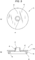
Fig. 5(a) is a plan view of an inner plug in the configuration of the cap ofFig. 1 , andFig. 5(b) is a cross sectional view ofFig. 4(a) . - In the following, a mode of carrying out the present invention will be described with reference to
Fig. 1 to Fig. 5 . - A cap 1 according to an embodiment of the present invention is configured from a
cap body 4 and alid member 5. Thecap body 4, as illustrated inFig. 1 , is fitted on a container openingportion 3 of thecontainer 2, and includes anejection hole 25 for content. Thelid member 5 is coupled with amain cap member 11 of thecap body 4 via ahinge 6. The cap 1 is configured by assembling three constituent members of: themain cap member 11 coupled with thelid member 5 and including anannular wall portion 10, as illustrated inFig. 2 ; acheck valve 12 illustrated inFig. 4 ; and aninner plug 13 illustrated inFig. 5 . Thelid member 5 may be configured as a separate member, instead of being coupled with thecap body 4 via thehinge 6. - As illustrated in
Fig. 1 , thecontainer 2 is an easily deformable container, such as a tube container, and is filled inside with a liquid content or a flowable content having viscosity. Examples of the content include soy sauce, olive oil, dressings, mayonnaise, ketchup, ton-katsu (pork cutlet) sauce, and mustard paste. Thecontainer 2 is the type of container from which the content is ejected through the application of an internal pressure applied by, for example, squeezing abody portion 2a thereof. The container openingportion 3 is formed in a cylindrical shape. On a lower outer wall surface of the container openingportion 3, amale screw portion 15 is formed. On an upper portion of the container openingportion 3, afitting wall portion 16 is formed, with an entire peripheral wall portion thereof protruding inward. It should be noted that the cap 1 may also be adopted for a double container (including a container referred to as a delamination container) comprising an outer container and an inner container. In this case, the cap 1 would be attached to the outercontainer opening portion 3 of theinner container 2, with the inner container being internally filled with the content. The inner container would have flexibility and would become shrunk and deformed as the content decreases. In order to maintain the reduced-volume shape of the inner container, the inner container is configured such that outer air can be suctioned between the outer container and the inner container. - The
cap body 4 is configured from: themain cap member 11, which is threadedly engaged with the container openingportion 3 and has a cylindrical shape; theannular wall portion 10; thecheck valve 12; and theinner plug 13. Theannular wall portion 10 extends integrally from an inner wall surface of a cylindricalinner wall portion 19 of themain cap member 11, toward the radial center and diagonally upward. Theannular wall portion 10 includes anejection hole 25 in a radially central portion. Thecheck valve 12 is disposed over theannular wall portion 10. Thecheck valve 12 opens and closes theejection hole 25 by avalve portion 36 being detached from or seated on anannular valve seat 26 around theejection hole 25. Theinner plug 13 is disposed over thecheck valve 12. Theinner plug 13 communicates with theejection hole 25, and includes anejection passageway 41 for the content from theejection hole 25. Thecheck valve 12 is molded from a synthetic resin having higher elasticity than that of a synthetic resin from which themain cap member 11 is molded. Specifically, the main cap member 11 (including the lid member 4) and theinner plug 13 are molded from polyethylene. Thecheck valve 12 is molded from polyethylene or elastomer. - As illustrated in
Fig. 1 andFig. 2 , themain cap member 11 is configured from: a cylindricalouter wall portion 18 threadedly engaged with thecontainer opening portion 3; the cylindricalinner wall portion 19; and an annularhorizontal wall portion 20 as a top surface portion. The cylindricalinner wall portion 19 is disposed concentrically inside the cylindricalouter wall portion 18. The annularhorizontal wall portion 20 connects the upper end of the cylindricalouter wall portion 18 and the upper end of the cylindricalinner wall portion 19. On the inner wall surface of the cylindricalouter wall portion 18, afemale screw portion 21 is formed in an entire axial area. Thefemale screw portion 21 is threadedly engaged with themale screw portion 15 provided on thecontainer opening portion 3. Between the cylindricalinner wall portion 19 and the cylindricalouter wall portion 18, anannular space 22 is formed. The upper end opening of the cylindricalinner wall portion 19 provides anopening portion 19a in which theinner plug 13 is fitted. In an outer peripheral portion on the upper surface of the annularhorizontal wall portion 20, an annular protrudingportion 17 which protrudes upward is formed. As illustrated inFig. 3 , the annular protrudingportion 17 has a cross sectional shape configured from a horizontally extendingupper surface 17a, a curvedinner surface 17b, and anouter surface 17c. The curvedinner surface 17b extends radially inward from one end on the inner side of theupper surface 17a, forming a smoothly curving recessed shape. Theouter surface 17c axially extends from the other end on the outer side of theupper surface 17a. Alternatively, theinner surface 17b may be formed as an inclined surface extending radially inward at an angle with respect to the axial direction. As illustrated inFig. 2(b) , in an upper inner wall surface of the cylindricalinner wall portion 19, an annularfitting recess portion 23 is formed extending annularly in a circumferential direction. - As illustrated in
Fig. 1 andFig. 2 , theannular wall portion 10 integrally extends from the entire area in the circumferential direction of a lower inner wall surface of the cylindricalinner wall portion 19, toward the radial center and diagonally upward. Theannular wall portion 10 has a truncated cone shape. Theannular wall portion 10 and the inner wall surface of the cylindricalinner wall portion 19 form an upwardlyopen space 24. In the radially center portion of theannular wall portion 10, there is theejection hole 25, which has a substantially circular shape. Theejection opening 25 communicates with the interior of thecontainer opening portion 3. Around theejection hole 25, theannular valve seat 26 is formed. Theannular valve seat 26 is formed on an inverted cone shapedsurface 28. At one location in the annular valve seat 26 (inverted cone shaped surface 28) of theannular wall portion 10, acirculation groove 27 is formed in the radial direction. Thecirculation groove 27 is formed on the opposite side from the side of thehinge 6. Thecirculation groove 27 is formed with a substantially U-shaped cross section. - The annular
horizontal wall portion 20 has an outer diameter which is smaller than an outer diameter of the cylindricalouter wall portion 18. On the outer wall surface of the annularhorizontal wall portion 20, a ridged lockingportion 31 is formed extending annularly in the circumferential direction. On the outer wall surface of the annularhorizontal wall portion 20, thelid member 5 is fitted. On the lower surface of the annularhorizontal wall portion 20 between the cylindricalouter wall portion 18 and the cylindricalinner wall portion 19, anannular seal portion 32 descends concentrically. The lower end of theannular seal portion 32 is closely contacted with the upper end of thecontainer opening portion 3. - As illustrated in
Fig. 1 andFig. 4 , thecheck valve 12 is configured from acylindrical support portion 34, a plurality ofelastic pieces 35, thevalve portion 36, and a plurality of circulation holes 37. Thecylindrical support portion 34 abuts on the inner wall surface of the cylindricalinner wall portion 19 of themain cap member 11. The plurality ofelastic pieces 35 extends integrally from the inner wall surface of thecylindrical support portion 34 toward radial center. Thevalve portion 36 is integrally connected to the distal end portion of each of theelastic pieces 35, and opens and closes theejection hole 25. The plurality of circulation holes 37 is provided between the respectiveelastic pieces 35. Through the circulation holes 37, the content from theejection hole 25 is circulated. - The
elastic pieces 35 extend from the upper inner wall surface of thecylindrical support portion 34 toward the radial center and diagonally downward, while slightly curving. In the present embodiment, theelastic pieces 35 are formed at four locations at a 90° pitch in the circumferential direction. Between theelastic pieces 35, the circulation holes 37 are formed at four locations at a 90° pitch. The distal end portion of each of theelastic pieces 35 is integrally connected to the upper edge of the outer peripheral portion of thevalve portion 36. Thevalve portion 36 has a dome shape. Specifically, thevalve portion 36 has a circular shape as viewed in plan, and includes an upwardly protruding curved wall portion. The outer peripheral portion of thevalve portion 36 is formed with an inverted cone shapedsurface 29 so as to be seated on the annular valve seat 26 (inverted cone shaped surface 28). From the upper surface of thevalve portion 36, a spherical protrudingportion 38 rises. - As illustrated in
Fig. 1 andFig. 5 , theinner plug 13 is disposed over thecheck valve 12. Theinner plug 13 is configured from acylindrical support portion 40, acylindrical guide portion 42, and an annularhorizontal wall portion 43. Thecylindrical support portion 40 is fitted on the cylindricalinner wall portion 19 of themain cap member 11. Thecylindrical guide portion 42 is concentrically disposed inside thecylindrical support portion 40, and includes theejection passageway 41 therein. The annularhorizontal wall portion 43 integrally connects the upper end of thecylindrical support portion 40 and the lower end of thecylindrical guide portion 42. The annularhorizontal wall portion 43 is formed with anannular flange portion 43a radially protruding from the outer peripheral surface of thecylindrical support portion 40. Between the lower wall surface of the annularhorizontal wall portion 43 and the inner wall surface of thecylindrical support portion 40, a plurality ofreinforcement ribs 45 is formed at intervals in the circumferential direction. Theannular flange portion 43a is formed so as to be slightly higher than the annular protrudingportion 17 provided on the upper surface of the outer peripheral portion of the annularhorizontal wall portion 20 of themain cap member 11. The upper surface from the annularhorizontal wall portion 43 to theannular flange portion 43a extends horizontally. The upper surface from the annularhorizontal wall portion 43 to theannular flange portion 43a may be formed as an inclined surface that is gradually downwardly inclined radially outward. Alternatively, theannular flange portion 43a may be omitted, and the upper surface of the annularhorizontal wall portion 43 and the upper surface (the bottom surface of an annular accumulatinggroove portion 33 which will be described later) of the annularhorizontal wall portion 20 of themain cap member 11 may be made flush. Thecylindrical support portion 40 is disposed over thecylindrical support portion 34 of thecheck valve 12. On the outer wall surface of thecylindrical support portion 40, anannular ridge portion 44 is formed extending in the circumferential direction. The peripheral wall portion of thecylindrical support portion 40 has a thickness which is substantially the same as the thickness of the peripheral wall portion of thecylindrical support portion 34 of thecheck valve 12. - As illustrated in
Fig. 1 andFig. 2 , thelid member 5 is integrally connected to the cylindricalouter wall portion 18 of themain cap member 11 via thehinge 6. Thelid member 5 is configured from acylindrical body portion 50 and atop surface portion 51. Thecylindrical body portion 50 is connected to the outer wall surface of the cylindricalouter wall portion 18 of themain cap member 11 via thehinge 6. Thetop surface portion 51 is integrally connected to the entire areas in the circumferential direction of the upper end of thebody portion 50. From the radially central portion of thetop surface portion 51, a cylindricalclose contact portion 52 descends. The cylindricalclose contact portion 52 is closely fitted in the upper end of thecylindrical guide portion 42 of theinner plug 13 of thecap body 4. Between thebody portion 50 and the cylindricalclose contact portion 52 of thetop surface portion 51, a cylindricalscattering suppression portion 55 descends. On the lower inner wall surface of thebody portion 50, formed is a ridged lockingportion 53 annularly extending in the circumferential direction. On the upper outer wall surface of thebody portion 50 on the opposite side from thehinge 6, a holdingportion 54 to be held by the user protrudes outward in a predetermined range in the circumferential direction. - A method for assembling the cap 1 and attaching the cap 1 to the
container opening portion 3 will be described. - First, the
check valve 12 is installed on the upper surface of theannular wall portion 10 of themain cap member 11 from above. Specifically, thecheck valve 12 is disposed on the upper surface of theannular wall portion 10 in such a way that the outer wall surface of thecylindrical support portion 34 of thecheck valve 12 lies along the inner wall surface of the cylindricalinner wall portion 19 of themain cap member 11. That is, thecheck valve 12 is installed from above into thespace 24 with an open top enclosed by theannular wall portion 10 and the inner wall surface of the cylindricalinner wall portion 19. - Then, the
inner plug 13 is disposed in theopening portion 19a of the cylindricalinner wall portion 19 of themain cap member 11. That is, theinner plug 13 is disposed in such a way that the outer wall surface of thecylindrical support portion 40 of theinner plug 13 lies along the inner wall surface of the cylindricalinner wall portion 19 of themain cap member 11. Theinner plug 13 is installed so as to push in thecheck valve 12. In this way, theannular ridge portion 44 provided on the outer wall surface of thecylindrical support portion 40 of theinner plug 13 is fitted in the annularfitting recess portion 23 provided on the inner wall surface of the cylindricalinner wall portion 19 of themain cap member 11. Also, theannular flange portion 43a of theinner plug 13 abuts on the upper surface of the annularhorizontal wall portion 20. In this way, theinner plug 13 is installed. As a result, the outer peripheral portion of the valve portion 36 (inverted cone shaped surface 29) of thecheck valve 12 becomes closely attached to the annular valve seat 26 (inverted cone shaped surface 28) around theejection hole 25 of theannular wall portion 10. In this case, the lower end (outer peripheral portion) of thevalve portion 36 of thecheck valve 12 is positioned higher than its position before installation. Accordingly, due to a downward urging force (recovery force) of theelastic pieces 35 that are curved, the outer peripheral portion of the valve portion 36 (inverted cone shaped surface 29) of thecheck valve 12 becomes closely contacted with the annular valve seat 26 (inverted cone shaped surface 28) around theejection hole 25 of theannular wall portion 10 so as to press theannular valve seat 26. Thecylindrical guide portion 42 of theinner plug 13 is positioned immediately over thevalve portion 36 of the check valve 12 (ejection hole 25). At an interval from the outer peripheral surface of theannular flange portion 43a of theinner plug 13 in the radial direction, the annular protrudingportion 17 provided on the annularhorizontal wall portion 20 of themain cap member 11 is positioned. In this way, between theannular flange portion 43a of theinner plug 13 and the annular protrudingportion 17 of themain cap member 11, the annular accumulatinggroove portion 33 is formed. Thus, the assembly of thecap body 4 is completed. - When the
lid member 5 is capped on thecap body 4, thehinge 6 is bent and thelid member 5 is disposed so as to cover thecap body 4 from above. Then, the ridged lockingportion 53 provided on thebody portion 50 of thelid member 5 becomes engaged across the ridged lockingportion 31 provided on the annularhorizontal wall portion 20 of themain cap member 11. Also, the cylindricalclose contact portion 52 provided on thetop surface portion 51 of thelid member 5 is closely fitted in the upper end of thecylindrical guide portion 42 of theinner plug 13 of thecap body 4. The cylindricalscattering suppression portion 55 provided on thelid member 5 is disposed on the upwardly extended line of thecylindrical support portion 40 of theinner plug 13. The lower end of the cylindricalscattering suppression portion 55 is disposed in proximity to the upper surface of the annularhorizontal wall portion 43. - When the
cap body 4 is attached to thecontainer opening portion 3, the peripheral wall portion of thecontainer opening portion 3 is inserted into theannular space 22 between the cylindricalinner wall portion 19 and the cylindricalouter wall portion 18 of thecap body 4. Further, themale screw portion 15 provided on the outer wall surface of thecontainer opening portion 3 and thefemale screw portion 21 provided on the inner wall surface of the cylindricalouter wall portion 18 of thecap body 4 are threadedly engaged with each other. As a result, the outer wall surface of the cylindricalinner wall portion 19 of themain cap member 11 is press-contacted by thefitting wall portion 16 of thecontainer opening portion 3. The lower end of theannular seal portion 32 descending from the lower surface of the annularhorizontal wall portion 20 of themain cap member 11 is closely contacted with the upper end of thecontainer opening portion 3. In this way, the attachment of the cap 1 to thecontainer opening portion 3 is completed. While in the present embodiment the method for attaching the cap 1 to thecontainer opening portion 3 by threaded engagement has been described, the cap may be attached by other attaching methods, such as by capping. - The operation of the cap 1 according to the embodiment of the present invention will be described.
- When the content is used, first the
lid member 5 is opened to externally expose theinner plug 13 of thecap body 4. - Then, the
container 2 is inclined and placed in an ejecting state where theejection passageway 41 of theinner plug 13 faces downward, and thebody portion 2a of thecontainer 2 is squeezed to apply internal pressure to thecontainer 2. In this way, the internal pressure of thecontainer 2 acts on the entire area of the lower wall surface of thevalve portion 36 of thecheck valve 12. As a result, theelastic pieces 35 of thecheck valve 12 are elastically deformed and bent, whereby the outer peripheral portion (inverted cone shaped surface 29) of thevalve portion 36 is detached from the annular valve seat 26 (inverted cone shaped surface 28) around theejection hole 25 of theannular wall portion 10. Consequently, theejection hole 25 of theannular wall portion 10 is opened, and an appropriate amount of the content is ejected outwardly from within thecontainer opening portion 3, via theejection hole 25, the circulation holes 37 of thecheck valve 12, and theejection passageway 41 of theinner plug 13. - Thereafter, when the squeezing of the
body portion 2a of thecontainer 2 is stopped, the internal pressure to thecontainer 2 is released, and theelastic pieces 35 of thecheck valve 12 recover. The outer peripheral portion (inverted cone shaped surface 29) of thevalve portion 36 is seated on the annular valve seat 26 (inverted cone shaped surface 28) around theejection hole 25 of theannular wall portion 10, and theejection hole 25 of theannular wall portion 10 is closed by thevalve portion 36. In this case, the content that was not ejected outwardly from theejection passageway 41 of theinner plug 13 returns back into thecontainer 2 via thecirculation groove 27. Thereafter, the pressing force from thevalve portion 26 to theannular valve seat 26 increases. Because thevalve portion 36 has elasticity, the opening area of thecirculation groove 27 decreases. Finally, the content blocks the opening of thecirculation groove 27 by surface tension, the opening being very small. Accordingly, the interior of thecontainer 2 can be maintained in a hermetically sealed state. Thus, while the content in thecap body 4 that was not ejected is returned into thecontainer 2, the interior of thecontainer 2 can be quickly hermetically sealed immediately after use, without the user manually operating the cap 1, and the entry of air into the interior of thecontainer 2 can be suppressed. - Next, the
hinge 6 is bent and thelid member 5 is moved to cover thecap body 4 from above. In this way, the ridged lockingportion 53 provided on thebody portion 50 of thelid member 5 becomes engaged so as to move across the ridged lockingportion 31 provided on the annularhorizontal wall portion 20 of the cap body 4 (main cap member 11). Also, the cylindricalclose contact portion 52 provided on thetop surface portion 51 of thelid member 5 is closely fitted in the upper end of thecylindrical guide portion 42 of theinner plug 13 of thecap body 4. - If, particularly in the case of a liquid content, some of the liquid content that has not been ejected and remains in the ejection passageway 41 (cylindrical guide portion 42) of the
inner plug 13, due to the fitting of the cylindricalclose contact portion 52 of thelid member 5 in thecylindrical guide portion 42 of theinner plug 13, the liquid content is scattered from within thecylindrical guide portion 42 and reaches the annularhorizontal wall portion 43 of theinner plug 13, while interfering with thetop surface portion 51 and the cylindricalscattering suppression portion 55 of thelid member 5. The liquid content, however, is blocked by the annular protrudingportion 17 provided on the annularhorizontal wall portion 20 of themain cap member 11, and is prevented from further flowing outward. The liquid content is accumulated in the annular accumulatinggroove portion 33 between theannular flange portion 43a of theinner plug 13 and the annular protrudingportion 17. Accordingly, hardly any of the scattered liquid content flows downward along the outer wall surface of the annularhorizontal wall portion 20 of themain cap member 11. Thus, the attachment of the liquid content onto the lower end inner peripheral surface of thebody portion 50 of thelid member 5 can be suppressed. When thelid member 5 is capped on thecap body 4, the entry of foreign matter into the cap body 4 (between theinner plug 13 and thecheck valve 12 and annular wall portion 10) is suppressed, and the interior of thecontainer 2 is doubly sealed. In addition, because the interior of thecap body 4 is sealed by thelid member 5, the small amount of content that may remain in thespace 24 over theannular wall portion 10 does not become oxidized. - As described above, in the cap 1 according to the embodiment of the present invention, the annular protruding
portion 17 is provided on the annular horizontal wall portion 20 (top surface portion) of the cap body 4 (main cap member 11) around theinner plug 13 at a radial interval. Between theannular flange portion 43a of theinner plug 13 and the annular protrudingportion 17, the annular accumulatinggroove portion 33 is provided. Particularly in the case of a liquid content, if some of the liquid content remains in thecylindrical guide portion 42 of theinner plug 13, the liquid content is scattered from within thecylindrical guide portion 42 when thelid member 5 is placed after use. The liquid content reaches the annularhorizontal wall portion 43 of theinner plug 13 after interfering with thetop surface portion 51 and the cylindricalscattering suppression portion 55 of thelid member 5. The liquid content, however, is blocked by the annular protrudingportion 17 provided on the annularhorizontal wall portion 20 of themain cap member 11, and is prevented from further flowing outward. The liquid content is accumulated in the annular accumulatinggroove portion 33 between theannular flange portion 43a of theinner plug 13 and the annular protrudingportion 17. Thus, the scattered liquid content does not flow downward along the outer wall surface of the annularhorizontal wall portion 20 of themain cap member 11. As a result, the attachment of the liquid content onto the lower end inner peripheral surface of thebody portion 50 of thelid member 5 can be suppressed, and the need for hygiene is also satisfied. - In addition, in the cap 1 according to the embodiment of the present invention, the inner surface of the annular protruding
portion 17 is formed as a curved surface curving in a recessed shape. Accordingly, the user easily wipes off the liquid content in the annular accumulatinggroove portion 33. - Furthermore, in the cap 1 according to the embodiment of the present invention, the annular protruding
portion 17 is provided on the annularhorizontal wall portion 20 of the cap body 4 (main cap member 11) around theinner plug 13 at a radial interval. Accordingly, in addition to the above-mentioned operation/effects, a malicious attempt to remove theinner plug 13 by inserting a sharp tool and the like between theannular flange portion 43a of theinner plug 13 and the annularhorizontal wall portion 20 of themain cap member 11 can be prevented. That is, the annular protrudingportion 17 makes it difficult to insert a sharp tool and the like between theannular flange portion 43a of theinner plug 13 and the annularhorizontal wall portion 20 of themain cap member 11. -
- 1
- Cap
- 2
- Container
- 3
- Container opening portion
- 4
- Cap body
- 5
- Lid member
- 6
- Hinge
- 10
- Annular wall portion
- 12
- Check valve
- 13
- Inner plug
- 17
- Annular protruding portion
- 17b
- Inner surface
- 19a
- Opening portion
- 20
- Annular horizontal wall portion (top surface portion)
- 25
- Ejection hole
- 26
- Annular valve seat
- 33
- Annular accumulating groove portion
- 36
- Valve portion
- 41
- Ejection passageway
- 50
- Lid member
Claims (2)
- A cap made from synthetic resin and comprising a cap body to be attached to a container opening portion and a lid member capped on the cap body,
the cap body including:an inner plug fitted in an opening portion of a top surface portion and having an ejection passageway;an annular wall portion having an ejection hole positioned in a radially central portion and communicating with the ejection passageway, and an annular valve seat provided around the ejection hole; anda check valve which is disposed between the annular wall portion and the inner plug and which is configured to open and close the ejection hole as a valve portion is detached from or seated on the annular valve seat, whereinan annular protruding portion is provided on the top surface portion around the inner plug at a radial interval therefrom. - The cap according to claim 1, wherein the annular protruding portion includes an inner surface on the inner plug side which is formed as an inclined surface or a curved surface inwardly from an upper end of the inner surface, the inclined surface being inclined with respect to an axial direction.
Applications Claiming Priority (2)
| Application Number | Priority Date | Filing Date | Title |
|---|---|---|---|
| JP2015069379A JP6537319B2 (en) | 2015-03-30 | 2015-03-30 | cap |
| PCT/JP2016/059658 WO2016158766A1 (en) | 2015-03-30 | 2016-03-25 | Cap |
Publications (3)
| Publication Number | Publication Date |
|---|---|
| EP3279109A1 true EP3279109A1 (en) | 2018-02-07 |
| EP3279109A4 EP3279109A4 (en) | 2018-12-19 |
| EP3279109B1 EP3279109B1 (en) | 2022-07-13 |
Family
ID=57004658
Family Applications (1)
| Application Number | Title | Priority Date | Filing Date |
|---|---|---|---|
| EP16772647.0A Active EP3279109B1 (en) | 2015-03-30 | 2016-03-25 | Cap |
Country Status (6)
| Country | Link |
|---|---|
| US (1) | US10259624B2 (en) |
| EP (1) | EP3279109B1 (en) |
| JP (1) | JP6537319B2 (en) |
| KR (1) | KR101932925B1 (en) |
| CN (1) | CN107531372B (en) |
| WO (1) | WO2016158766A1 (en) |
Families Citing this family (12)
| Publication number | Priority date | Publication date | Assignee | Title |
|---|---|---|---|---|
| JP6548440B2 (en) * | 2015-04-15 | 2019-07-24 | 東京ライト工業株式会社 | Container and cap |
| JP6820169B2 (en) * | 2016-08-31 | 2021-01-27 | 株式会社吉野工業所 | Discharge container |
| RU2742456C1 (en) * | 2017-02-01 | 2021-02-05 | Силган Диспенсинг Системз Хемер Гмбх | Releasing device for liquid medium |
| JP7031993B2 (en) * | 2018-07-31 | 2022-03-08 | 株式会社吉野工業所 | Double container cap |
| CN109132178A (en) * | 2018-10-23 | 2019-01-04 | 爱索尔(广州)包装有限公司 | A kind of sidespin container cover |
| JP7363022B2 (en) * | 2018-10-29 | 2023-10-18 | 東洋製罐株式会社 | Nozzle member with valve body, discharge cap, and injection mold |
| WO2021028602A1 (en) * | 2019-08-15 | 2021-02-18 | Obrist Closures Switzerland Gmbh | Closure |
| JP7152029B2 (en) * | 2019-11-05 | 2022-10-12 | 株式会社トーヨー工芸工業 | One-touch nozzle cap |
| JP7541441B2 (en) * | 2020-03-02 | 2024-08-28 | サーモス株式会社 | Cap unit and container with cap |
| CN111939995A (en) * | 2020-08-14 | 2020-11-17 | 三门颜临医疗器械有限公司 | Test tube with dumping rubber head |
| US11860017B2 (en) | 2022-02-28 | 2024-01-02 | L'oreal | Cosmetic dispenser with bladder valve system |
| US11904330B2 (en) | 2022-02-28 | 2024-02-20 | L'oreal | Cosmetic dispenser with accordion bladder valve system |
Family Cites Families (57)
| Publication number | Priority date | Publication date | Assignee | Title |
|---|---|---|---|---|
| BE630794A (en) * | 1962-04-10 | |||
| US3245429A (en) * | 1963-01-08 | 1966-04-12 | Pressure Products Ind Inc | Poppet valve |
| CH418865A (en) * | 1963-12-03 | 1966-08-15 | Migros | Bottle stopper made of plastic material |
| US4350179A (en) * | 1980-09-26 | 1982-09-21 | Bunn Stuart E | Valve assembly with relief groove |
| DE8235857U1 (en) * | 1982-12-21 | 1984-05-24 | Wella Ag, 6100 Darmstadt | Automatic closure for flexible containers |
| JPS63177260A (en) | 1987-01-19 | 1988-07-21 | Hitachi Ltd | automatic transaction device |
| US4785978A (en) * | 1987-03-02 | 1988-11-22 | Japan Crown Cork Co., Ltd. | Container closure provided with automatic opening-closing mechanism |
| JPS63177260U (en) * | 1987-05-07 | 1988-11-16 | ||
| JP2841707B2 (en) | 1990-05-16 | 1998-12-24 | 松下電器産業株式会社 | Thermal head drive |
| JPH0421465U (en) * | 1990-06-12 | 1992-02-24 | ||
| US5207250A (en) * | 1991-10-08 | 1993-05-04 | Tsao Ye Ming | Pollutant-proof contractible container |
| IT221941Z2 (en) * | 1991-10-10 | 1994-12-29 | Sofar Spa | NON-RETURN VALVE CAN BE USED IN PARTICULAR IN A LIQUID PRESSURE DISPENSING CONTAINER |
| IL123227A0 (en) * | 1998-02-08 | 1998-09-24 | 3By Ltd | Check valve |
| JP2001039462A (en) * | 1999-05-21 | 2001-02-13 | Takeuchi Press Ind Co Ltd | Mouth of container with liquid receiver |
| JP4580524B2 (en) * | 2000-09-12 | 2010-11-17 | 株式会社日本点眼薬研究所 | Discharge container with filter |
| DE10109064A1 (en) * | 2001-02-24 | 2002-09-05 | Beiersdorf Ag | Opening system with back ventilation mechanism |
| JP4749572B2 (en) * | 2001-03-13 | 2011-08-17 | 大成化工株式会社 | Dispensing container plug structure |
| US6616012B2 (en) * | 2001-07-27 | 2003-09-09 | Richard C. G. Dark | Fluid dispensing valve and method of use |
| FR2833579B1 (en) * | 2001-12-13 | 2004-10-08 | Plastohm Sa | STERILE DISPENSING SYSTEM FOR A PRODUCT CONTAINED IN A CONTAINER, IN PARTICULAR A FLEXIBLE TUBE |
| JP4129811B2 (en) * | 2002-04-30 | 2008-08-06 | 株式会社吉野工業所 | Dispensing container |
| JP2004067099A (en) * | 2002-06-10 | 2004-03-04 | Katsutoshi Masuda | Valve mechanism |
| JP2004083013A (en) * | 2002-06-26 | 2004-03-18 | Katsutoshi Masuda | Valve mechanism |
| DE10303605A1 (en) * | 2003-01-30 | 2004-08-19 | Gaplast Gmbh | One-way valve device |
| JP4357183B2 (en) * | 2003-02-14 | 2009-11-04 | 大成化工株式会社 | Delaminated bottle and method for producing the same |
| CN2661601Y (en) * | 2003-10-24 | 2004-12-08 | 罗良军 | Sanitary bottle nipple |
| CN1626412A (en) * | 2004-07-06 | 2005-06-15 | 蔡刚强 | A kind of residual liquid reflux container mouth |
| JP2006044660A (en) * | 2004-07-30 | 2006-02-16 | Katsutoshi Masuda | Fluid storage container |
| US7195138B2 (en) * | 2005-08-25 | 2007-03-27 | Continental Afa Dispensing Company | Container closure with biased closed valve |
| US7198180B2 (en) * | 2005-09-08 | 2007-04-03 | Continental Afa Dispensing Company | Container closure with biased closed tube valve |
| DE102006005608B4 (en) * | 2006-02-06 | 2007-10-11 | Heraeus Kulzer Gmbh | Dental container with evaporator-sealable dropper insert |
| BRPI0716676A2 (en) * | 2006-11-14 | 2013-09-24 | Carbonite Corp Sociedade Do Panama | "closure for a multi-component container and multi-component container" |
| FR2927064B1 (en) * | 2008-02-04 | 2010-03-26 | Rexam Pharma | LIQUID DISTRIBUTION TIP, AND PACKAGING ASSEMBLY AND LIQUID DISPENSING COMPRISING SUCH A TIP. |
| JP5224915B2 (en) * | 2008-06-03 | 2013-07-03 | 大成化工株式会社 | Discharge container with filter |
| KR100969651B1 (en) * | 2008-07-23 | 2010-07-14 | 주식회사 아이팩 | Leakage prevention device for tube container |
| FR2937018B1 (en) * | 2008-10-15 | 2012-06-01 | Rexam Pharma La Verpilliere | LIQUID DISPENSING DEVICE HAVING A DISPLACABLE SEALING MEMBER UNDER THE EFFECT OF A USER'S PRESSURE |
| GB0822447D0 (en) * | 2008-12-09 | 2009-01-14 | Carbonite Corp | Dispensing containers |
| JP5531013B2 (en) * | 2009-05-22 | 2014-06-25 | 大塚製薬株式会社 | Eye drops container |
| EP2558380B1 (en) * | 2010-04-12 | 2016-06-01 | Hoffmann Neopac AG | Tube with one-way valve for discharge regulation in tubes and method for manufacturing such a one-way valve |
| DE102011007396A1 (en) * | 2011-04-14 | 2012-10-18 | Ing. Erich Pfeiffer Gmbh | Discharge head for a tube and tube with discharge head |
| JP5667010B2 (en) * | 2011-06-09 | 2015-02-12 | 株式会社吉野工業所 | Discharge container |
| US20140183154A1 (en) * | 2011-07-25 | 2014-07-03 | Jan Essebaggers | Self closing flow control device with adjustable actuator element for container closures |
| JP6336702B2 (en) * | 2011-08-05 | 2018-06-06 | キッコーマン株式会社 | Discharge container |
| CA2853508C (en) * | 2011-10-31 | 2020-10-27 | Yoshino Kogyosho Co., Ltd. | Discharge container |
| SG11201403052TA (en) * | 2011-12-26 | 2014-10-30 | Yoshino Kogyosho Co Ltd | Squeezable container |
| WO2013168244A1 (en) * | 2012-05-09 | 2013-11-14 | 大成化工株式会社 | Mouth plug for liquid container |
| JP2013241197A (en) * | 2012-05-21 | 2013-12-05 | Daiwa Can Co Ltd | Cap |
| JP6059489B2 (en) * | 2012-09-28 | 2017-01-11 | 株式会社吉野工業所 | Discharge container |
| US9669973B2 (en) * | 2013-06-28 | 2017-06-06 | Yoshino Kogyosho Co., Ltd. | Double-walled container |
| WO2015047997A1 (en) * | 2013-09-24 | 2015-04-02 | The Procter & Gamble Company | Vented container for viscous liquids |
| DE102013226253B4 (en) * | 2013-12-17 | 2016-03-24 | Aptar Radolfzell Gmbh | Protective cap for a dispenser and dispenser for dispensing pharmaceutical and / or cosmetic liquids |
| US9676525B2 (en) * | 2013-12-17 | 2017-06-13 | Aptar Radolfzell Gmbh | Protective cap for a dispenser, and discharge device for discharging pharmaceutical and/or cosmetical liquids |
| US10071836B2 (en) * | 2014-04-16 | 2018-09-11 | Reckitt Benckiser (Brands) Limited | Dosing dispensing closure |
| KR102110129B1 (en) * | 2014-05-14 | 2020-06-08 | 도쿄 라이트 고교 가부시키가이샤 | Cap |
| JP3194661U (en) * | 2014-09-22 | 2014-12-04 | 株式会社トーヨー工芸工業 | Liquid leak prevention cap for double containers |
| JP6548440B2 (en) * | 2015-04-15 | 2019-07-24 | 東京ライト工業株式会社 | Container and cap |
| US9555426B2 (en) * | 2015-06-29 | 2017-01-31 | Westrock Slatersville, Llc | Measured dose dispensers and methods of using the same |
| GB201516189D0 (en) * | 2015-09-14 | 2015-10-28 | Obrist Closures Switzerland | Head stand closure with a tamper-evident seal |
-
2015
- 2015-03-30 JP JP2015069379A patent/JP6537319B2/en active Active
-
2016
- 2016-03-25 CN CN201680026103.2A patent/CN107531372B/en active Active
- 2016-03-25 KR KR1020177031333A patent/KR101932925B1/en active Active
- 2016-03-25 EP EP16772647.0A patent/EP3279109B1/en active Active
- 2016-03-25 WO PCT/JP2016/059658 patent/WO2016158766A1/en not_active Ceased
- 2016-03-25 US US15/562,676 patent/US10259624B2/en active Active
Also Published As
| Publication number | Publication date |
|---|---|
| EP3279109A4 (en) | 2018-12-19 |
| EP3279109B1 (en) | 2022-07-13 |
| US10259624B2 (en) | 2019-04-16 |
| KR101932925B1 (en) | 2018-12-27 |
| JP2016188101A (en) | 2016-11-04 |
| CN107531372A (en) | 2018-01-02 |
| CN107531372B (en) | 2019-10-15 |
| US20180086516A1 (en) | 2018-03-29 |
| KR20170131673A (en) | 2017-11-29 |
| WO2016158766A1 (en) | 2016-10-06 |
| JP6537319B2 (en) | 2019-07-03 |
Similar Documents
| Publication | Publication Date | Title |
|---|---|---|
| EP3279109B1 (en) | Cap | |
| EP3284693B1 (en) | Container and cap | |
| KR102110129B1 (en) | Cap | |
| US8485398B2 (en) | One-way valve | |
| JP5963323B2 (en) | cap | |
| DE102010009102A1 (en) | packaging | |
| JP2013241197A (en) | Cap | |
| JP6552287B2 (en) | cap | |
| WO2020017648A1 (en) | Cap | |
| JP2017193352A (en) | cap | |
| JP5959570B2 (en) | cap | |
| JP6899582B2 (en) | cap | |
| JP2016055921A (en) | cap | |
| US20190240687A1 (en) | Manually-operated spray pump having self-sealing nozzle | |
| JP2016216050A (en) | cap | |
| JP2015217953A (en) | cap | |
| JP6352207B2 (en) | Dispensing cap and container having the same | |
| EP2578320B1 (en) | Self-sealing dispenser insert and method for assembling the same | |
| JP2020164186A (en) | Hinge cap |
Legal Events
| Date | Code | Title | Description |
|---|---|---|---|
| STAA | Information on the status of an ep patent application or granted ep patent |
Free format text: STATUS: THE INTERNATIONAL PUBLICATION HAS BEEN MADE |
|
| PUAI | Public reference made under article 153(3) epc to a published international application that has entered the european phase |
Free format text: ORIGINAL CODE: 0009012 |
|
| STAA | Information on the status of an ep patent application or granted ep patent |
Free format text: STATUS: REQUEST FOR EXAMINATION WAS MADE |
|
| 17P | Request for examination filed |
Effective date: 20171020 |
|
| AK | Designated contracting states |
Kind code of ref document: A1 Designated state(s): AL AT BE BG CH CY CZ DE DK EE ES FI FR GB GR HR HU IE IS IT LI LT LU LV MC MK MT NL NO PL PT RO RS SE SI SK SM TR |
|
| AX | Request for extension of the european patent |
Extension state: BA ME |
|
| DAV | Request for validation of the european patent (deleted) | ||
| DAX | Request for extension of the european patent (deleted) | ||
| A4 | Supplementary search report drawn up and despatched |
Effective date: 20181120 |
|
| RIC1 | Information provided on ipc code assigned before grant |
Ipc: B65D 47/20 20060101ALI20181114BHEP Ipc: B65D 47/40 20060101AFI20181114BHEP |
|
| GRAP | Despatch of communication of intention to grant a patent |
Free format text: ORIGINAL CODE: EPIDOSNIGR1 |
|
| STAA | Information on the status of an ep patent application or granted ep patent |
Free format text: STATUS: GRANT OF PATENT IS INTENDED |
|
| INTG | Intention to grant announced |
Effective date: 20220223 |
|
| GRAS | Grant fee paid |
Free format text: ORIGINAL CODE: EPIDOSNIGR3 |
|
| GRAA | (expected) grant |
Free format text: ORIGINAL CODE: 0009210 |
|
| STAA | Information on the status of an ep patent application or granted ep patent |
Free format text: STATUS: THE PATENT HAS BEEN GRANTED |
|
| AK | Designated contracting states |
Kind code of ref document: B1 Designated state(s): AL AT BE BG CH CY CZ DE DK EE ES FI FR GB GR HR HU IE IS IT LI LT LU LV MC MK MT NL NO PL PT RO RS SE SI SK SM TR |
|
| REG | Reference to a national code |
Ref country code: CH Ref legal event code: EP |
|
| REG | Reference to a national code |
Ref country code: DE Ref legal event code: R096 Ref document number: 602016073506 Country of ref document: DE |
|
| REG | Reference to a national code |
Ref country code: IE Ref legal event code: FG4D |
|
| REG | Reference to a national code |
Ref country code: AT Ref legal event code: REF Ref document number: 1504179 Country of ref document: AT Kind code of ref document: T Effective date: 20220815 |
|
| REG | Reference to a national code |
Ref country code: LT Ref legal event code: MG9D |
|
| REG | Reference to a national code |
Ref country code: NL Ref legal event code: MP Effective date: 20220713 |
|
| PG25 | Lapsed in a contracting state [announced via postgrant information from national office to epo] |
Ref country code: SE Free format text: LAPSE BECAUSE OF FAILURE TO SUBMIT A TRANSLATION OF THE DESCRIPTION OR TO PAY THE FEE WITHIN THE PRESCRIBED TIME-LIMIT Effective date: 20220713 Ref country code: RS Free format text: LAPSE BECAUSE OF FAILURE TO SUBMIT A TRANSLATION OF THE DESCRIPTION OR TO PAY THE FEE WITHIN THE PRESCRIBED TIME-LIMIT Effective date: 20220713 Ref country code: PT Free format text: LAPSE BECAUSE OF FAILURE TO SUBMIT A TRANSLATION OF THE DESCRIPTION OR TO PAY THE FEE WITHIN THE PRESCRIBED TIME-LIMIT Effective date: 20221114 Ref country code: NO Free format text: LAPSE BECAUSE OF FAILURE TO SUBMIT A TRANSLATION OF THE DESCRIPTION OR TO PAY THE FEE WITHIN THE PRESCRIBED TIME-LIMIT Effective date: 20221013 Ref country code: NL Free format text: LAPSE BECAUSE OF FAILURE TO SUBMIT A TRANSLATION OF THE DESCRIPTION OR TO PAY THE FEE WITHIN THE PRESCRIBED TIME-LIMIT Effective date: 20220713 Ref country code: LV Free format text: LAPSE BECAUSE OF FAILURE TO SUBMIT A TRANSLATION OF THE DESCRIPTION OR TO PAY THE FEE WITHIN THE PRESCRIBED TIME-LIMIT Effective date: 20220713 Ref country code: LT Free format text: LAPSE BECAUSE OF FAILURE TO SUBMIT A TRANSLATION OF THE DESCRIPTION OR TO PAY THE FEE WITHIN THE PRESCRIBED TIME-LIMIT Effective date: 20220713 Ref country code: FI Free format text: LAPSE BECAUSE OF FAILURE TO SUBMIT A TRANSLATION OF THE DESCRIPTION OR TO PAY THE FEE WITHIN THE PRESCRIBED TIME-LIMIT Effective date: 20220713 Ref country code: ES Free format text: LAPSE BECAUSE OF FAILURE TO SUBMIT A TRANSLATION OF THE DESCRIPTION OR TO PAY THE FEE WITHIN THE PRESCRIBED TIME-LIMIT Effective date: 20220713 |
|
| REG | Reference to a national code |
Ref country code: AT Ref legal event code: MK05 Ref document number: 1504179 Country of ref document: AT Kind code of ref document: T Effective date: 20220713 |
|
| PG25 | Lapsed in a contracting state [announced via postgrant information from national office to epo] |
Ref country code: PL Free format text: LAPSE BECAUSE OF FAILURE TO SUBMIT A TRANSLATION OF THE DESCRIPTION OR TO PAY THE FEE WITHIN THE PRESCRIBED TIME-LIMIT Effective date: 20220713 Ref country code: IS Free format text: LAPSE BECAUSE OF FAILURE TO SUBMIT A TRANSLATION OF THE DESCRIPTION OR TO PAY THE FEE WITHIN THE PRESCRIBED TIME-LIMIT Effective date: 20221113 Ref country code: HR Free format text: LAPSE BECAUSE OF FAILURE TO SUBMIT A TRANSLATION OF THE DESCRIPTION OR TO PAY THE FEE WITHIN THE PRESCRIBED TIME-LIMIT Effective date: 20220713 Ref country code: GR Free format text: LAPSE BECAUSE OF FAILURE TO SUBMIT A TRANSLATION OF THE DESCRIPTION OR TO PAY THE FEE WITHIN THE PRESCRIBED TIME-LIMIT Effective date: 20221014 |
|
| REG | Reference to a national code |
Ref country code: DE Ref legal event code: R097 Ref document number: 602016073506 Country of ref document: DE |
|
| PG25 | Lapsed in a contracting state [announced via postgrant information from national office to epo] |
Ref country code: SM Free format text: LAPSE BECAUSE OF FAILURE TO SUBMIT A TRANSLATION OF THE DESCRIPTION OR TO PAY THE FEE WITHIN THE PRESCRIBED TIME-LIMIT Effective date: 20220713 Ref country code: RO Free format text: LAPSE BECAUSE OF FAILURE TO SUBMIT A TRANSLATION OF THE DESCRIPTION OR TO PAY THE FEE WITHIN THE PRESCRIBED TIME-LIMIT Effective date: 20220713 Ref country code: DK Free format text: LAPSE BECAUSE OF FAILURE TO SUBMIT A TRANSLATION OF THE DESCRIPTION OR TO PAY THE FEE WITHIN THE PRESCRIBED TIME-LIMIT Effective date: 20220713 Ref country code: CZ Free format text: LAPSE BECAUSE OF FAILURE TO SUBMIT A TRANSLATION OF THE DESCRIPTION OR TO PAY THE FEE WITHIN THE PRESCRIBED TIME-LIMIT Effective date: 20220713 Ref country code: AT Free format text: LAPSE BECAUSE OF FAILURE TO SUBMIT A TRANSLATION OF THE DESCRIPTION OR TO PAY THE FEE WITHIN THE PRESCRIBED TIME-LIMIT Effective date: 20220713 |
|
| PLBE | No opposition filed within time limit |
Free format text: ORIGINAL CODE: 0009261 |
|
| STAA | Information on the status of an ep patent application or granted ep patent |
Free format text: STATUS: NO OPPOSITION FILED WITHIN TIME LIMIT |
|
| PG25 | Lapsed in a contracting state [announced via postgrant information from national office to epo] |
Ref country code: SK Free format text: LAPSE BECAUSE OF FAILURE TO SUBMIT A TRANSLATION OF THE DESCRIPTION OR TO PAY THE FEE WITHIN THE PRESCRIBED TIME-LIMIT Effective date: 20220713 Ref country code: EE Free format text: LAPSE BECAUSE OF FAILURE TO SUBMIT A TRANSLATION OF THE DESCRIPTION OR TO PAY THE FEE WITHIN THE PRESCRIBED TIME-LIMIT Effective date: 20220713 |
|
| 26N | No opposition filed |
Effective date: 20230414 |
|
| PG25 | Lapsed in a contracting state [announced via postgrant information from national office to epo] |
Ref country code: AL Free format text: LAPSE BECAUSE OF FAILURE TO SUBMIT A TRANSLATION OF THE DESCRIPTION OR TO PAY THE FEE WITHIN THE PRESCRIBED TIME-LIMIT Effective date: 20220713 |
|
| PG25 | Lapsed in a contracting state [announced via postgrant information from national office to epo] |
Ref country code: SI Free format text: LAPSE BECAUSE OF FAILURE TO SUBMIT A TRANSLATION OF THE DESCRIPTION OR TO PAY THE FEE WITHIN THE PRESCRIBED TIME-LIMIT Effective date: 20220713 |
|
| PG25 | Lapsed in a contracting state [announced via postgrant information from national office to epo] |
Ref country code: MC Free format text: LAPSE BECAUSE OF FAILURE TO SUBMIT A TRANSLATION OF THE DESCRIPTION OR TO PAY THE FEE WITHIN THE PRESCRIBED TIME-LIMIT Effective date: 20220713 |
|
| REG | Reference to a national code |
Ref country code: CH Ref legal event code: PL |
|
| REG | Reference to a national code |
Ref country code: BE Ref legal event code: MM Effective date: 20230331 |
|
| PG25 | Lapsed in a contracting state [announced via postgrant information from national office to epo] |
Ref country code: LU Free format text: LAPSE BECAUSE OF NON-PAYMENT OF DUE FEES Effective date: 20230325 |
|
| REG | Reference to a national code |
Ref country code: IE Ref legal event code: MM4A |
|
| PG25 | Lapsed in a contracting state [announced via postgrant information from national office to epo] |
Ref country code: LI Free format text: LAPSE BECAUSE OF NON-PAYMENT OF DUE FEES Effective date: 20230331 Ref country code: IT Free format text: LAPSE BECAUSE OF FAILURE TO SUBMIT A TRANSLATION OF THE DESCRIPTION OR TO PAY THE FEE WITHIN THE PRESCRIBED TIME-LIMIT Effective date: 20220713 Ref country code: IE Free format text: LAPSE BECAUSE OF NON-PAYMENT OF DUE FEES Effective date: 20230325 Ref country code: CH Free format text: LAPSE BECAUSE OF NON-PAYMENT OF DUE FEES Effective date: 20230331 |
|
| PG25 | Lapsed in a contracting state [announced via postgrant information from national office to epo] |
Ref country code: BE Free format text: LAPSE BECAUSE OF NON-PAYMENT OF DUE FEES Effective date: 20230331 |
|
| PGFP | Annual fee paid to national office [announced via postgrant information from national office to epo] |
Ref country code: GB Payment date: 20240320 Year of fee payment: 9 |
|
| PGFP | Annual fee paid to national office [announced via postgrant information from national office to epo] |
Ref country code: FR Payment date: 20240328 Year of fee payment: 9 |
|
| PG25 | Lapsed in a contracting state [announced via postgrant information from national office to epo] |
Ref country code: BG Free format text: LAPSE BECAUSE OF FAILURE TO SUBMIT A TRANSLATION OF THE DESCRIPTION OR TO PAY THE FEE WITHIN THE PRESCRIBED TIME-LIMIT Effective date: 20220713 |
|
| PG25 | Lapsed in a contracting state [announced via postgrant information from national office to epo] |
Ref country code: BG Free format text: LAPSE BECAUSE OF FAILURE TO SUBMIT A TRANSLATION OF THE DESCRIPTION OR TO PAY THE FEE WITHIN THE PRESCRIBED TIME-LIMIT Effective date: 20220713 |
|
| PG25 | Lapsed in a contracting state [announced via postgrant information from national office to epo] |
Ref country code: CY Free format text: LAPSE BECAUSE OF FAILURE TO SUBMIT A TRANSLATION OF THE DESCRIPTION OR TO PAY THE FEE WITHIN THE PRESCRIBED TIME-LIMIT; INVALID AB INITIO Effective date: 20160325 |
|
| PG25 | Lapsed in a contracting state [announced via postgrant information from national office to epo] |
Ref country code: HU Free format text: LAPSE BECAUSE OF FAILURE TO SUBMIT A TRANSLATION OF THE DESCRIPTION OR TO PAY THE FEE WITHIN THE PRESCRIBED TIME-LIMIT; INVALID AB INITIO Effective date: 20160325 |
|
| GBPC | Gb: european patent ceased through non-payment of renewal fee |
Effective date: 20250325 |
|
| PG25 | Lapsed in a contracting state [announced via postgrant information from national office to epo] |
Ref country code: TR Free format text: LAPSE BECAUSE OF FAILURE TO SUBMIT A TRANSLATION OF THE DESCRIPTION OR TO PAY THE FEE WITHIN THE PRESCRIBED TIME-LIMIT Effective date: 20220713 |
|
| PG25 | Lapsed in a contracting state [announced via postgrant information from national office to epo] |
Ref country code: GB Free format text: LAPSE BECAUSE OF NON-PAYMENT OF DUE FEES Effective date: 20250325 |
|
| PG25 | Lapsed in a contracting state [announced via postgrant information from national office to epo] |
Ref country code: FR Free format text: LAPSE BECAUSE OF NON-PAYMENT OF DUE FEES Effective date: 20250331 |
|
| PGFP | Annual fee paid to national office [announced via postgrant information from national office to epo] |
Ref country code: DE Payment date: 20260319 Year of fee payment: 11 |