EP3278756B1 - System und verfahren zum ändern des betriebszustandes einer vorrichtung - Google Patents
System und verfahren zum ändern des betriebszustandes einer vorrichtung Download PDFInfo
- Publication number
- EP3278756B1 EP3278756B1 EP17184296.6A EP17184296A EP3278756B1 EP 3278756 B1 EP3278756 B1 EP 3278756B1 EP 17184296 A EP17184296 A EP 17184296A EP 3278756 B1 EP3278756 B1 EP 3278756B1
- Authority
- EP
- European Patent Office
- Prior art keywords
- state
- detection device
- accordance
- operator
- image
- Prior art date
- Legal status (The legal status is an assumption and is not a legal conclusion. Google has not performed a legal analysis and makes no representation as to the accuracy of the status listed.)
- Active
Links
Images


Classifications
-
- A—HUMAN NECESSITIES
- A61—MEDICAL OR VETERINARY SCIENCE; HYGIENE
- A61B—DIAGNOSIS; SURGERY; IDENTIFICATION
- A61B34/00—Computer-aided surgery; Manipulators or robots specially adapted for use in surgery
- A61B34/20—Surgical navigation systems; Devices for tracking or guiding surgical instruments, e.g. for frameless stereotaxis
-
- A—HUMAN NECESSITIES
- A61—MEDICAL OR VETERINARY SCIENCE; HYGIENE
- A61B—DIAGNOSIS; SURGERY; IDENTIFICATION
- A61B90/00—Instruments, implements or accessories specially adapted for surgery or diagnosis and not covered by any of the groups A61B1/00 - A61B50/00, e.g. for luxation treatment or for protecting wound edges
- A61B90/36—Image-producing devices or illumination devices not otherwise provided for
- A61B90/361—Image-producing devices, e.g. surgical cameras
-
- G—PHYSICS
- G02—OPTICS
- G02B—OPTICAL ELEMENTS, SYSTEMS OR APPARATUS
- G02B27/00—Optical systems or apparatus not provided for by any of the groups G02B1/00 - G02B26/00, G02B30/00
- G02B27/01—Head-up displays
- G02B27/017—Head mounted
-
- A—HUMAN NECESSITIES
- A61—MEDICAL OR VETERINARY SCIENCE; HYGIENE
- A61B—DIAGNOSIS; SURGERY; IDENTIFICATION
- A61B17/00—Surgical instruments, devices or methods
- A61B2017/00017—Electrical control of surgical instruments
-
- A—HUMAN NECESSITIES
- A61—MEDICAL OR VETERINARY SCIENCE; HYGIENE
- A61B—DIAGNOSIS; SURGERY; IDENTIFICATION
- A61B17/00—Surgical instruments, devices or methods
- A61B2017/00017—Electrical control of surgical instruments
- A61B2017/00212—Electrical control of surgical instruments using remote controls
-
- A—HUMAN NECESSITIES
- A61—MEDICAL OR VETERINARY SCIENCE; HYGIENE
- A61B—DIAGNOSIS; SURGERY; IDENTIFICATION
- A61B17/00—Surgical instruments, devices or methods
- A61B2017/00017—Electrical control of surgical instruments
- A61B2017/00221—Electrical control of surgical instruments with wireless transmission of data, e.g. by infrared radiation or radiowaves
-
- A—HUMAN NECESSITIES
- A61—MEDICAL OR VETERINARY SCIENCE; HYGIENE
- A61B—DIAGNOSIS; SURGERY; IDENTIFICATION
- A61B17/00—Surgical instruments, devices or methods
- A61B2017/00681—Aspects not otherwise provided for
- A61B2017/00734—Aspects not otherwise provided for battery operated
-
- A—HUMAN NECESSITIES
- A61—MEDICAL OR VETERINARY SCIENCE; HYGIENE
- A61B—DIAGNOSIS; SURGERY; IDENTIFICATION
- A61B34/00—Computer-aided surgery; Manipulators or robots specially adapted for use in surgery
- A61B34/20—Surgical navigation systems; Devices for tracking or guiding surgical instruments, e.g. for frameless stereotaxis
- A61B2034/2046—Tracking techniques
- A61B2034/2055—Optical tracking systems
-
- A—HUMAN NECESSITIES
- A61—MEDICAL OR VETERINARY SCIENCE; HYGIENE
- A61B—DIAGNOSIS; SURGERY; IDENTIFICATION
- A61B34/00—Computer-aided surgery; Manipulators or robots specially adapted for use in surgery
- A61B34/20—Surgical navigation systems; Devices for tracking or guiding surgical instruments, e.g. for frameless stereotaxis
- A61B2034/2046—Tracking techniques
- A61B2034/2055—Optical tracking systems
- A61B2034/2057—Details of tracking cameras
-
- A—HUMAN NECESSITIES
- A61—MEDICAL OR VETERINARY SCIENCE; HYGIENE
- A61B—DIAGNOSIS; SURGERY; IDENTIFICATION
- A61B34/00—Computer-aided surgery; Manipulators or robots specially adapted for use in surgery
- A61B34/20—Surgical navigation systems; Devices for tracking or guiding surgical instruments, e.g. for frameless stereotaxis
- A61B2034/2046—Tracking techniques
- A61B2034/2065—Tracking using image or pattern recognition
-
- A—HUMAN NECESSITIES
- A61—MEDICAL OR VETERINARY SCIENCE; HYGIENE
- A61B—DIAGNOSIS; SURGERY; IDENTIFICATION
- A61B90/00—Instruments, implements or accessories specially adapted for surgery or diagnosis and not covered by any of the groups A61B1/00 - A61B50/00, e.g. for luxation treatment or for protecting wound edges
- A61B90/36—Image-producing devices or illumination devices not otherwise provided for
- A61B90/37—Surgical systems with images on a monitor during operation
- A61B2090/372—Details of monitor hardware
-
- A—HUMAN NECESSITIES
- A61—MEDICAL OR VETERINARY SCIENCE; HYGIENE
- A61B—DIAGNOSIS; SURGERY; IDENTIFICATION
- A61B90/00—Instruments, implements or accessories specially adapted for surgery or diagnosis and not covered by any of the groups A61B1/00 - A61B50/00, e.g. for luxation treatment or for protecting wound edges
- A61B90/36—Image-producing devices or illumination devices not otherwise provided for
- A61B90/37—Surgical systems with images on a monitor during operation
- A61B2090/373—Surgical systems with images on a monitor during operation using light, e.g. by using optical scanners
-
- A—HUMAN NECESSITIES
- A61—MEDICAL OR VETERINARY SCIENCE; HYGIENE
- A61B—DIAGNOSIS; SURGERY; IDENTIFICATION
- A61B90/00—Instruments, implements or accessories specially adapted for surgery or diagnosis and not covered by any of the groups A61B1/00 - A61B50/00, e.g. for luxation treatment or for protecting wound edges
- A61B90/39—Markers, e.g. radio-opaque or breast lesions markers
- A61B2090/3937—Visible markers
-
- A—HUMAN NECESSITIES
- A61—MEDICAL OR VETERINARY SCIENCE; HYGIENE
- A61B—DIAGNOSIS; SURGERY; IDENTIFICATION
- A61B90/00—Instruments, implements or accessories specially adapted for surgery or diagnosis and not covered by any of the groups A61B1/00 - A61B50/00, e.g. for luxation treatment or for protecting wound edges
- A61B90/50—Supports for surgical instruments, e.g. articulated arms
- A61B2090/502—Headgear, e.g. helmet, spectacles
-
- A—HUMAN NECESSITIES
- A61—MEDICAL OR VETERINARY SCIENCE; HYGIENE
- A61B—DIAGNOSIS; SURGERY; IDENTIFICATION
- A61B90/00—Instruments, implements or accessories specially adapted for surgery or diagnosis and not covered by any of the groups A61B1/00 - A61B50/00, e.g. for luxation treatment or for protecting wound edges
- A61B90/90—Identification means for patients or instruments, e.g. tags
- A61B90/94—Identification means for patients or instruments, e.g. tags coded with symbols, e.g. text
- A61B90/96—Identification means for patients or instruments, e.g. tags coded with symbols, e.g. text using barcodes
Definitions
- the invention relates to a system for changing the operating state of at least one electrically operated device, in particular a medical device.
- the device can in particular be a medical device, and the present invention is explained below using the example of such a medical device, but is not limited to this field of application.
- the U.S. 2016/0000514 A1 describes a surgical tool and display device for performing surgical procedures, including a head-mounted device having a frame for positioning a visual display in a viewer's field of view.
- a controller is attached to a portion of the frame and configured to generate a computer generated image on the visual display.
- a visual display including an active side for projecting a computer generated image, is in electrical communication with the control unit and is attached to the Control unit mounted in such a way that the active side is visible in the field of view.
- a digital image source contains at least one image file that is characteristic of an anatomical or pathological feature of the patient.
- a display is carried by the operator or is placed between the operator and the patient during surgery. The display is selectively transparent and presents the operator with an image derived from the image file.
- An image controller reads the image file from the image source and controls the display such that at least a portion of the image can be displayed and modified by the operator at his or her will.
- a plurality of peripheral devices are each configured to receive an image control input from the operator and, in response, to generate an image control signal.
- the object of the present invention is to provide a system for changing an operating state of at least one electrically operated device that allows user-friendly handling of the device.
- the system includes a detection device on a carrying device that can be worn on the body of an operator and, in particular, can be held in a detachable manner.
- "On the body” in the present case includes clothing worn by the operator or an object otherwise attached to the body.
- the operator can move in such a way that the detection device is aligned with the at least one object.
- the object can if in detection range arranged in the detection device, detected and identified by it.
- a signal may be communicated to the at least one device associated with or forming the at least one object, and the device may transition from the first state to the be transferred to the second state. In this way there is a user-friendly possibility for the operator to act on the at least one device.
- the signal can be transmitted to the device by the detection device directly or indirectly, for example via a control device.
- the system may include a variety of devices and objects. Each device may have one or more objects associated with it. Each object can be associated with one or more devices.
- the handling of the system is improved in that the at least one device is only transferred from the first state to the second state or vice versa if the at least one object is detected by the detection device for a predetermined or predeterminable period of time. For example, a period of a few seconds is provided so that a change in the state of the at least one device does not occur every time the detection range sweeps over the at least one object, even for a very short time. For example, it may be necessary to identify the at least one object over the specified or specifiable period of time.
- the system proves to be particularly advantageous if the at least one device is battery-operated. For example, this makes it possible to switch on the battery-operated device as required by switching it from the first to the second state and preferably to switch it back from the second state to the first state and switch it off after the end of use.
- the runtime of battery-powered devices can thereby be increased. On-demand, user-friendly activation of battery powered devices is possible.
- the first state can in particular be a switched-off state of the at least one device and the second state can be at least one switched-on state of the at least one device or vice versa. This proves to be particularly advantageous in combination with battery-operated devices.
- the first state is a first operating state of the at least one device and the second state is a second operating state of the at least one device in a switched-on state of the same.
- the first and the second state are, for example, different operating stages or operating modes of the at least one device.
- the first state is a stand-by state, which the at least one device can assume to save energy.
- the second state can be an activated operating state.
- the detection device is configured optically and is or includes a camera for detecting the at least one object.
- This allows a structurally simple configuration of the system and in particular a contactless detection of the at least one object in the detection area.
- it is preferably possible to detect the at least one object over a larger distance range from the detection device, for example from a few tens of centimeters to a few meters.
- the object can be identified and a signal can be sent to the appropriate device.
- the detection device is preferably in operative connection wirelessly with the at least one device, in particular via a radio link. This does not restrict the operator's freedom of movement. For example, a signal from the detection device using Bluetooth (in particular Bluetooth Low Energy) to the at least one device.
- Bluetooth in particular Bluetooth Low Energy
- At least one battery for supplying energy to the detection device is advantageously held on the carrying device.
- the carrying device can be arranged on the operator's head. Due to the arrangement on the head, movements of the head, which lead to a movement of the operator's eyes and thus the operator's field of vision, are converted into a movement of the carrying device with the detection device. As a result, the detection device can be aimed as specifically as possible at the at least one object in a structurally simple and user-friendly manner.
- the carrying device is or includes spectacles or a spectacle frame.
- this can be understood in particular to mean that the carrying device can be worn in the manner of spectacles or a spectacle frame. It is not necessary for spectacle lenses, ground or unground, to be available. For example, a frame to put on or put on the ears and nose is sufficient.
- the carrying device with the detection device is designed as data glasses.
- This preferably has, as will be discussed below, a display device.
- a control device coupled to the detection device and/or the display device can also be part of the data glasses.
- the display device and the control device can be held on the glasses or on the glasses frame.
- the carrying device is or includes a headband or a hood.
- the device assumes the second state as long as the at least one object is detected by the detection device, and otherwise assumes the first state.
- the device remains in this state after assuming the second state and can be transferred from the second state to the first state if the at least one object is again detected by the detection device and a relevant signal is transmitted to the at least one device.
- the at least one device assumes the second state for a predetermined or predeterminable period of time and then returns to the first state.
- the at least one object is a marking element.
- the marking element can be or comprise a sticker or a plaque, for example.
- a code can be stored on the marking element, for example a matrix code.
- the marker element can be an encoded marker or an AR marker.
- the marking element can be fixed to the at least one device.
- the at least one device can be optically detected by the detection device as the at least one object in order to recognize the at least one device based on its characteristic features, in particular shape and/or color.
- Image processing algorithms can be stored in the detection device for analyzing recordings that are created by the detection device.
- the recordings are analyzed to determine whether the at least one object can be identified, for example by characteristic Features of the at least one device or by characteristic features of the aforesaid marking element.
- a device is provided with at least one drivable surgical processing tool, the first state and the second state being linked to the drive of the processing tool. This makes it possible to act on the drive of the machining tool in a way that is easy to handle.
- the device is battery operated.
- the processing tool is, for example, a surgical drilling tool or a surgical sawing tool.
- a device is provided with at least one light-emitting element, the first state and the second state being linked to the light-emitting state of the light-emitting element.
- the lighting element can be part of an endoscopic lighting device, for example. It is also conceivable that the light-emitting element is part of a surgical navigation system in order to illuminate medical marking elements that can be detected by it.
- the device can be battery operated.
- an imaging device with at least one camera is provided, with the first state and the second state being linked to the provision of an image from the camera.
- the device can be battery operated.
- the imaging device is, for example, an endoscopic device.
- the imaging device can also be a surgical navigation system be, for example with a stereo camera, the images of which can be used to determine position data for medical marking elements.
- the at least one device has a display device with an image display on which image content relating to the operation of the at least one device can be displayed. Provision can be made here in particular for image content to be able to be displayed on the image display as a function of the first state and/or second state. This includes the possibility that in one of the states the display of an image content is omitted, ie the display device does not display anything.
- a display device with an image display is provided as the device, the first state and the second state being linked to image content of the image display, including the possibility that in one state the display of image content can be omitted. In a way that is easy to handle, this gives the opportunity to act on the display device.
- the display device can be battery operated.
- the display device is held on the carrying device. It is particularly favorable if there are data glasses with a display device for displaying the image content for the operator.
- the data glasses already mentioned above can accordingly be provided with a display device.
- the display device can show the operator image content that is preferably linked to the first state and the second state and can depend on the respective state.
- the invention makes it possible, for example, to provide the user with a type of “virtual monitor”.
- a type of “virtual monitor” For example, an object in the form of a marking element is arranged on a wall, floor space, table surface or otherwise. The object is detected and identified by aligning the detection device arranged on the data glasses. Image content can be displayed on the display device of the data glasses, which the user can view as being shown on the “virtual monitor” so to speak.
- the object mentioned at the beginning is also achieved by a method for changing the operating state of at least one electrically operated device in a system of the type mentioned above, the detection device being aligned with the at least one object by movement of the operator and the at least one object in a detection range of the detection device is positioned and detected and identified by it, with the detection device transmitting a relevant signal to the at least one device when the object is identified in such a way that the at least one device is transferred from the first state to the second state, the at least one device only then is transferred from the first state to the second state or vice versa if the at least one object is detected by the detection device for a predetermined or predeterminable period of time.
- figure 5 another preferred embodiment of a system according to the invention with a device in the form of a navigation system.
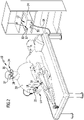
- FIG 1 shows an advantageous embodiment of a system according to the invention, denoted by reference numeral 10 .
- the system 10 includes a medical device 12.
- the device 12 is battery operated.
- the device 12 may include a surgical processing tool 14 including, for example, a surgical drill 16 .
- a drive 18 for the drill 16 can be provided, which is arranged, for example, in a grip element 22 that can be held by an operator 20 .
- the device 12 can include a control unit 24 which is coupled to the processing tool 14 via an electrical line 26 .
- At least one battery (not shown in the drawing) for providing electrical energy for the device 12 can be arranged in the control device 24 .
- An object 28 is assigned to the device 12 , with the object 28 being assigned in particular to the device 12 in a one-to-one manner. In the presence of other devices not shown in the drawing, a one-to-one relationship can exist with a respective additional object.
- the object 28 is a marking element 30 with a code 32.
- the marking element can, for example, be an AR marker or a coded marker and have a matrix code.
- the marking element 30 is for Example designed in the form of a sticker and fixed to the device 12.
- the system 10 also includes data glasses 34 with a spectacle frame 36.
- the spectacle frame 36 forms a carrying device 37. Spectacle lenses can be present, but this is not necessary.
- the data glasses 34 can be worn on the head by the operator 20 in a manner known per se via the carrying device 37, resting on the ears and nose. If the head moves, the data glasses 34 are moved as well. If the operator 20 aligns his head with a target, for example the object 28 , the data glasses 34 are also oriented towards the object 28 .
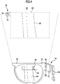
- the figure 4 shows an enlarged representation of the data glasses 34 in sections.
- the data glasses 34 shown therein are used in all of the systems according to the invention explained here.
- a detection device 38 is held on the spectacle frame 36 , which is designed optically and includes a camera 40 . Furthermore, a control device 42 can be held on the spectacle frame 36 .
- the control device 42 can be coupled to the detection device 38 or integrated into it, ie a combined detection device/control device can be present. In the following, it is assumed, without limitation, that the control device 42 is formed separately from the detection device 38 and is coupled to it.
- a rechargeable battery 44 can be held on the spectacle frame 36 to supply energy to the data glasses 34 .
- the system 10 also includes a display device 46 on the data glasses 34 which is coupled to the control device 42 .
- the display device 46 includes an image display on which image content is displayed by the control device 42 being represented. This is not discussed further in connection with the embodiment of the system 10; this is done in the explanation of the further advantageous embodiments of the system according to the invention.
- the detection device 38 includes a detection area 48 which is defined by a field of view of the camera 40 .
- the camera 40 is arranged on the data glasses 34 such that when the operator 20 is looking straight ahead and wearing the data glasses 34 as intended, the camera 40 with the field of view and thus the detection area 48 forms a central section of the field of view of the operator 20 .
- the camera 40 can capture a portion of what the operator 20 sees.
- the operator 20 can align the camera 40 with the marking element 30 by moving his head and thus the data glasses 34 .
- the marking element 30 is then positioned in the detection area 48 and is detected by the camera 40 . Recordings from camera 40 are analyzed by recording device 38 to determine whether features of marking element 30 were recorded.
- a relevant signal is transmitted from the detection device 38 via the control device 42 to the device 12 assigned to the marking element 30 .
- the signal is transmitted to control unit 24 .
- the signal is transmitted wirelessly, for example using the Bluetooth Low Energy standard.
- device 12 can be transitioned from a first state to a second state.
- Present is the the first state is a switched-off state of the device 12, in which the drive 18 in particular is deactivated.
- device 12 Upon receipt of the signal, device 12 is placed in the second state, an on state.
- the drive 18 is activated. this is in figure 2 symbolized by indicated vibrations of the machining tool 14. Also, this is in figure 2 symbolized by lit display elements 50 on control unit 24 .
- the device 12 is not switched from the switched-off state to the switched-on state until the marking element 30 has been detected and identified by the camera 40 for a predeterminable or predetermined period of time, for example a few seconds.
- the device 12 remains activated in the system 10 in the second state until the operator 20 sights the marker 30 again and aligns the detection area 48 with the marker 30 for its detection by the camera 40 and identification.
- the device 12 can again be informed of a change in the operating state by the detection device 38 via the control device 42 with a signal.
- the device 12 is transitioned from the on state to the off state.
- the device 12 assumes the second state for a specifiable or predetermined period of time and then returns to the first state.
- the use of the system 10 in battery-operated devices is particularly favorable. In a user-friendly and simple manner, these can also be switched on and off by the operator 20 from a distance, so that the energy of the battery(ies) can be saved and the running time of the devices can be increased.
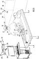
- the system 60 shown uses a device 62, which in the present case is an imaging and, in particular, an endoscopic device.
- the device 62 is also battery operated.
- the device 62 includes an endoscope 64 with a camera 65 which has, for example, an image sensor arranged in a grip element 66 .
- the endoscope 64 includes a shaft 68 that can be inserted into the patient's body.
- the endoscope 64 is connected to a control unit 72 via a connecting line 70 .
- the object 28 is optionally arranged on the control unit 72, designed as a marking element 30 with the code 32.
- the system 60 includes an object 74 which is also designed as a marking element 76 with a code 78 . Codes 78 and 32 match when both markers 30, 76 are provided. Object 74 is associated with device 62 .
- the marking element 76 is fixed to a fixed or movable wall 80 in the operating room.
- the wall 80 defines a virtual screen or monitor, indicated schematically by a dotted border 82 . It can be provided that the wall 80 actually has a border 82 attached in physical form.
- the device 62 can be switched from a first to a second state and in particular from an off state to an on state when the marking element 76 is detected and identified by the camera 40 and the device 62 transmits a relevant signal from the detection device 38 via the control device 42 becomes.
- an image is provided by the camera 65 of the endoscopic device 62 .
- Information relating to the image content is transmitted wirelessly from the device 62, in particular by radio, to the data glasses 34 and in particular to their control device 42.
- the image provided by the endoscope 64 is displayed on the image display of the display device 46 . This is in figure 4 shown schematically, with an object 84 in the patient's body lying in the field of view of the camera 65 of the endoscope 64 being shown to the operator 20 on the display device 46 .
- the wall 80 acts as a virtual screen or virtual monitor for the operator 20 .
- the operator 20 gets the impression that the object 84 is actually being displayed on the wall 80 . This is indicated by the dashed representation of item 84 within border 82 in FIG figure 4 symbolizes.
- the device 62 remains, for example, in the second state (on state) for as long as the marking element 76 is detected by the camera 40 . If the operator 20 turns his gaze away from the marking element 76 so that this is outside the detection area 48, the device 62 is switched back to the first state (off state). In addition, the object 84 is not displayed via the display device 46.
- the system 60 there is therefore in particular the possibility of displaying the image content in the image display of the display device 46 as a function of the first and of the second state.
- the respective image content is related to the condition of the Device 62 linked, the image content also depends on the object detected by the camera 65 of the endoscope 64 .
- the marking element 30 is also present, there is also the possibility of transferring the device 62 between the different states when the marking element 30 is detected by the camera 40.
- the system 60 can have a further object 86 embodied as a marking element 88 with a code 90 .
- the marking element 88 is likewise fixed to the wall 80 and defines a virtual screen or a virtual monitor, which is symbolized by a dot-dash border 92 .
- image content can be superimposed on the image display of the display device 46 in a way that the operator 20 can see.
- This image content can be viewed by the operator 20 as being displayed on the virtual monitor or the virtual screen.
- the display device 46 can therefore form a device 94 of the system, which can be transferred from a first state (here switched off state) into a second state (here switched on state) and vice versa.
- the image content is not faded in if the operator 20 averts his gaze from the marking element 88 in such a way that it can no longer be captured by the camera 40 .
- the system 100 shown schematically comprises a device 102, here in the form of a surgical navigation system 104.
- the device 102 can be battery operated.
- the navigation system 104 includes at least one, and in this case two, light-emitting elements 106 and also a stereo camera 108.
- Light emitted by the light-emitting elements 106 can be emitted by marking elements 110
- Surgical marking device 112 are reflected and captured by the stereo camera 108. This makes it possible to identify the position and the orientation of the marking device 112 and to track a part of the patient's body referenced therewith.
- the device 102 is assigned an object 114, configured as a marking element 116 with a code 118. If the marking element 116 is detected by the camera 40 in the detection area 48, the device 102 can be transferred from a first state to a second state. In this case, in particular, the light-emitting elements 106 are switched from an off state to an on state in order to emit light. In addition, the stereo camera 108 is changed from an off state to an on state. The light reflected by the marking elements 110 can be detected and image information can be provided by the stereo camera 108 .
- Image content based on the image information from the stereo camera 108 can be displayed to the operator 20 on the image display of the display device 46 , as explained using the example of the system 60 .
- the image content appears to be displayed on the virtual monitor or the virtual screen.
- the device 102 can assume the second state, for example, as long as the marking element 116 is detected by the camera 40 . If this detection is omitted, the device 102 can be transferred again from the second state to the first state.
- the light-emitting elements 106 and the stereo camera 108 can assume the switched-off state.
Landscapes
- Health & Medical Sciences (AREA)
- Surgery (AREA)
- Life Sciences & Earth Sciences (AREA)
- Engineering & Computer Science (AREA)
- General Health & Medical Sciences (AREA)
- Animal Behavior & Ethology (AREA)
- Veterinary Medicine (AREA)
- Nuclear Medicine, Radiotherapy & Molecular Imaging (AREA)
- Public Health (AREA)
- Physics & Mathematics (AREA)
- Biomedical Technology (AREA)
- Heart & Thoracic Surgery (AREA)
- Medical Informatics (AREA)
- Molecular Biology (AREA)
- Oral & Maxillofacial Surgery (AREA)
- General Physics & Mathematics (AREA)
- Optics & Photonics (AREA)
- Pathology (AREA)
- Robotics (AREA)
- Endoscopes (AREA)
Description
- Die Erfindung betrifft ein System zum Ändern des Betriebszustandes mindestens einer elektrisch betriebenen Vorrichtung, insbesondere einer medizintechnischen Vorrichtung.
- Offenbart ist ferner ein Verfahren zum Ändern des Betriebszustandes mindestens einer elektrisch betriebenen Vorrichtung, insbesondere einer medizintechnischen Vorrichtung.
- Die Vorrichtung kann insbesondere eine medizintechnische Vorrichtung sein, und die vorliegende Erfindung wird nachfolgend am Beispiel einer derartigen medizintechnischen Vorrichtung erläutert, ist jedoch nicht auf dieses Anwendungsgebiet beschränkt.
- Während einer Operation können von einem Operateur und dessen Assistenten eine Vielzahl unterschiedlicher elektrisch betriebener Vorrichtungen zum Einsatz kommen. Wünschenswert wäre es, die Bedienung elektrisch betriebener Vorrichtungen zu vereinfachen.
- Die
US 2016/0000514 A1 beschreibt ein chirurgisches Werkzeug und eine Anzeigeeinrichtung zum Durchführen chirurgischer Verfahren, wobei ein am Kopf tragbares Gerät vorgesehen ist, das einen Rahmen zum Positionieren einer optischen Anzeige im Sichtfeld eines Betrachters aufweist. Eine Steuereinheit ist an einem Abschnitt des Rahmens angebracht und dazu ausgebildet, an der optischen Anzeige ein computergeneriertes Bild zu erzeugen. Eine optische Anzeige, umfassend eine aktive Seite zum Projizieren eines computergenerierten Bildes, steht elektrisch mit der Steuereinheit in Verbindung und ist an der Steuereinheit derart angebracht, so dass die aktive Seite im Sichtfeld sichtbar ist. - Die
WO 2015/164402 A1 beschreibt ein intra-operatives medizintechnisches Bildbetrachtungssystem, das es einem Chirurgen erlaubt, eine Betrachtungsperspektive auf den Patienten aufrechtzuerhalten, während optische Bilder im laufenden Betrieb aufgerufen werden. Eine digitale Bildquelle enthält mindestens eine Bilddatei, die charakteristisch für ein anatomisches oder pathologisches Merkmal des Patienten ist. Eine Anzeige wird vom Operateur getragen oder ist während der Operation zwischen dem Operateur und dem Patienten angeordnet. Die Anzeige ist selektiv transparent und stellt dem Operateur ein Bild dar, das aus der Bilddatei abgeleitet ist. Eine Bildsteuereinheit liest die Bilddatei von der Bildquelle und steuert die Anzeige derart, so dass zumindest ein Abschnitt des Bildes angezeigt und vom Operateur nach dessen Willen modifiziert werden kann. Eine Mehrzahl von Peripheriegeräten sind jeweils dazu ausgestaltet, einen Bildsteuereingang vom Operateur zu empfangen und, als Antwort darauf, ein Bildsteuersignal zu erzeugen. - Aufgabe der vorliegenden Erfindung ist es, ein System zum Ändern eines Betriebszustandes mindestens einer elektrisch betriebenen Vorrichtung bereitzustellen, das eine benutzerfreundliche Handhabung der Vorrichtung ermöglicht.
- Diese Aufgabe wird durch ein erfindungsgemäßes System zum Ändern des Betriebszustandes mindestens einer elektrisch betriebenen Vorrichtung mit den Merkmalen von Anspruch 1 gelöst.
- Das System umfasst eine Erfassungseinrichtung an einer Trageinrichtung, die am Körper einer Bedienperson tragbar und insbesondere lösbar halterbar ist. "Am Körper" schließt vorliegend eine Kleidung der Bedienperson oder einen anderweitig am Körper befestigten Gegenstand mit ein. Die Bedienperson kann sich derart bewegen, dass die Erfassungseinrichtung auf das mindestens eine Objekt ausgerichtet wird. Das Objekt kann, wenn im Erfassungsbereich der Erfassungseinrichtung angeordnet, von dieser erfasst und identifiziert werden. Der mindestens einen Vorrichtung, die mit dem mindestens einen Objekt verknüpft ist oder die das mindestens eine Objekt bildet, kann ein Signal übermittelt werden, und die Vorrichtung kann vom ersten Zustand in den zweiten Zustand überführt werden. Auf diese Weise ist eine benutzerfreundliche Möglichkeit für die Bedienperson vorhanden, auf die mindestens eine Vorrichtung einzuwirken. Dabei besteht insbesondere die Möglichkeit, das mindestens eine Objekt kontaktlos zu erfassen. Eine kontaktlose Erfassung ist beispielsweise durch eine von der Erfassungseinrichtung umfasste oder gebildete Kamera möglich.
- Das Signal kann der Vorrichtung von der Erfassungseinrichtung direkt oder indirekt, beispielsweise über eine Steuereinrichtung, übermittelbar sein.
- Das System kann eine Mehrzahl von Vorrichtungen und Objekten umfassen. Jeder Vorrichtung kann/können ein oder mehrere Objekt zugeordnet sein. Jedes Objekt kann einer oder mehreren Vorrichtungen zugeordnet sein.
- Die Handhabung des Systems wird dadurch verbessert, dass die mindestens eine Vorrichtung nur dann vom ersten Zustand in den zweiten Zustand oder umgekehrt überführt wird, wenn das mindestens eine Objekt für eine vorgegebene oder vorgebbare Zeitdauer von der Erfassungseinrichtung erfasst wird. Beispielsweise ist eine Zeitdauer von wenigen Sekunden vorgesehen, damit eine Zustandsänderung an der mindestens einen Vorrichtung nicht jedes Mal dann eintritt, wenn der Erfassungsbereich das mindestens eine Objekt auch nur für sehr kurze Zeit überstreicht. Beispielsweise kann erforderlich sein, das mindestens eine Objekt über die vorgegebene oder vorgebbare Zeitdauer zu identifizieren.
- Als besonders vorteilhaft erweist sich das System, wenn die mindestens eine Vorrichtung batteriebetrieben ist. Beispielsweise gibt dies die Möglichkeit, die batteriebetriebene Vorrichtung durch Überführen vom ersten in den zweiten Zustand bei Bedarf einzuschalten und vorzugsweise nach Beendigung des Einsatzes wieder vom zweiten Zustand in den ersten Zustand zu überführen und abzuschalten. Die Laufzeit batteriebetriebener Vorrichtungen kann dadurch gesteigert werden. Es ist eine bedarfsabhängige, benutzerfreundliche Aktivierung batteriebetriebener Vorrichtungen möglich.
- Der erste Zustand kann insbesondere ein Ausschaltzustand der mindestens einen Vorrichtung sein und der zweite Zustand mindestens ein Einschaltzustand der mindestens einen Vorrichtung oder umgekehrt. Dies erweist sich insbesondere in Kombination mit batteriebetriebenen Vorrichtungen als vorteilhaft.
- Alternativ ist es von Vorteil, wenn der erste Zustand ein erster Betriebszustand der mindestens einen Vorrichtung ist und der zweite Zustand ein zweiter Betriebszustand der mindestens einen Vorrichtung in einem eingeschalteten Zustand derselben. Der erste und der zweite Zustand sind beispielsweise unterschiedliche Betriebsstufen oder Betriebsmodi der mindestens einen Vorrichtung. Beispielsweise ist der erste Zustand ein Stand-by-Zustand, den die mindestens eine Vorrichtung energiesparend einnehmen werden kann. Der zweite Zustand kann ein aktivierter Betriebszustand sein.
- Von Vorteil ist es, wenn die Erfassungseinrichtung optisch ausgestaltet ist und eine Kamera zum Erfassen des mindestens einen Objektes ist oder umfasst. Dies erlaubt eine konstruktiv einfache Ausgestaltung des Systems und insbesondere eine berührungslose Erfassung des mindestens einen Objektes im Erfassungsbereich. Dabei ist vorzugsweise eine Erfassung des mindestens einen Objektes über einen größeren Abstandsbereich von der Erfassungseinrichtung möglich, beispielsweise von einigen zehn Zentimetern bis zu einigen Metern. Das Objekt kann identifiziert werden, und der entsprechenden Vorrichtung kann ein Signal übermittelt werden.
- Vorzugsweise steht die Erfassungseinrichtung kabellos mit der mindestens einen Vorrichtung in Wirkverbindung, insbesondere über eine Funkverbindung. Die Bedienperson wird dadurch in ihrer Bewegungsfreiheit nicht eingeschränkt. Beispielsweise wird ein Signal von der Erfassungseinrichtung mittels Bluetooth (insbesondere Bluetooth Low Energy) an die mindestens eine Vorrichtung übertragen.
- Vorteilhafterweise ist an der Trageinrichtung mindestens eine Batterie zur Energieversorgung der Erfassungseinrichtung gehalten.
- Günstig ist es, wenn die Trageinrichtung am Kopf der Bedienperson anordenbar ist. Durch die Anordnung am Kopf werden Bewegungen des Kopfes, die zu einer Bewegung der Augen der Bedienperson und damit des Sichtfeldes der Bedienperson führen, in eine Bewegung der Trageinrichtung mit der Erfassungseinrichtung überführt. Die Erfassungseinrichtung kann dadurch auf konstruktiv einfache Weise und benutzerfreundlich möglichst gezielt auf das mindestens eine Objekt ausgerichtet werden.
- Bei einer vorteilhaften Ausführungsform des Systems ist oder umfasst die Trageinrichtung eine Brille oder ein Brillengestell. Darunter kann vorliegend insbesondere verstanden werden, dass die Trageinrichtung nach Art einer Brille oder eines Brillengestelles getragen werden kann. Nicht erforderlich ist, dass Brillengläser, geschliffen oder ungeschliffen, vorhanden sind. Ausreichend ist beispielsweise ein Gestell zum An- oder Auflegen an den Ohren und der Nase.
- Bei einer besonders vorteilhaften Ausführungsform ist die Trageinrichtung mit der Erfassungseinrichtung als Datenbrille ausgestaltet. Diese weist vorzugsweise, darauf wird nachfolgend noch eingegangen, eine Anzeigeeinrichtung auf. Eine mit der Erfassungseinrichtung und/oder der Anzeigeeinrichtung gekoppelte Steuereinrichtung kann ebenfalls Bestandteil der Datenbrille sein. Die Anzeigeeinrichtung und die Steuereinrichtung können an der Brille oder am Brillengestell gehalten sein.
- Bei einer andersartigen vorteilhaften Ausführungsform des Systems ist oder Umfasst die Trageinrichtung ein Stirnband oder eine Haube.
- Es kann vorgesehen sein, dass die Vorrichtung den zweiten Zustand solange einnimmt, wie das mindestens eine Objekt von der Erfassungseinrichtung erfasst wird, und anderenfalls den ersten Zustand einnimmt.
- Alternativ kann vorgesehen sein, dass die Vorrichtung nach der Einnahme des zweiten Zustandes in diesem verbleibt und vom zweiten Zustand in den ersten Zustand überführbar ist, wenn das mindestens eine Objekt von der Erfassungseinrichtung erneut erfasst und der mindestens einen Vorrichtung ein diesbezügliches Signal übermittelt wird.
- Alternativ kann vorgesehen sein, dass die mindestens eine Vorrichtung für eine vorgegebene oder vorgebbare Zeitdauer den zweiten Zustand einnimmt und anschließend in den ersten Zustand zurückkehrt.
- Als vorteilhaft erweist es sich, wenn das mindestens eine Objekt ein Markierelement ist. Das Markierelement kann zum Beispiel ein Aufkleber oder eine Plakette sein oder umfassen. Am Markierelement kann ein Code hinterlegt sein, beispielsweise ein Matrixcode. Das Markierelement kann ein codierter Marker oder ein AR-Marker sein.
- Das Markierelement kann an der mindestens einen Vorrichtung festgelegt sein.
- Bei einer andersartigen vorteilhaften Ausführungsform ist es günstig, wenn als das mindestens eine Objekt die mindestens eine Vorrichtung von der Erfassungseinrichtung optisch erfassbar ist zum Erkennen der mindestens einen Vorrichtung anhand von deren charakteristischen Merkmalen, insbesondere Form und/oder Farbe.
- In der Erfassungseinrichtung können Bildverarbeitungsalgorithmen hinterlegt sein zum Analysieren von Aufnahmen, die von der Erfassungseinrichtung erstellt werden. Die Aufnahmen werden dahingehend analysiert, ob das mindestens eine Objekt identifiziert werden kann, zum Beispiel durch charakteristisehe Merkmale der mindestens einen Vorrichtung oder durch charakteristische Merkmale des vorstehend genannten Markierelementes.
- Eine vorteilhafte Ausführungsform des Systems sieht vor, dass eine Vorrichtung mit mindestens einem antreibbaren chirurgischen Bearbeitungswerkzeug vorgesehen ist, wobei der erste Zustand und der zweite Zustand mit dem Antrieb des Bearbeitungswerkzeuges verknüpft sind. Dies gibt die Möglichkeit, handhabungsfreundlich auf den Antrieb des Bearbeitungswerkzeuges einzuwirken. Vorteilhafterweise ist die Vorrichtung batteriebetrieben. Das Bearbeitungswerkzeug ist zum Beispiel ein chirurgisches Bohrwerkzeug oder ein chirurgisches Sägewerkzeug.
- Alternativ oder ergänzend ist es günstig, wenn eine Vorrichtung mit mindestens einem Leuchtelement vorgesehen ist, wobei der erste Zustand und der zweite Zustand mit dem Leuchtzustand des Leuchtelementes verknüpft sind. Dies gibt die Möglichkeit, handhabungsfreundlich auf den Leuchtzustand des Leuchtelementes einzuwirken. Das Leuchtelement kann zum Beispiel Bestandteil einer endoskopischen Leuchteinrichtung sein. Denkbar ist auch, dass das Leuchtelement Bestandteil eines chirurgischen Navigationssystems ist, um von diesem erfassbare medizinische Markierelemente zu beleuchten. Die Vorrichtung kann batteriebetrieben sein.
- Alternativ oder ergänzend ist es günstig, wenn eine bildgebende Vorrichtung mit mindestens einer Kamera vorgesehen ist, wobei der erste Zustand und der zweite Zustand mit einer Bereitstellung eines Bildes der Kamera verknüpft sind. Dies gibt auf handhabungsfreundliche Weise die Möglichkeit, auf die Bereitstellung eines Bildes einzuwirken. Beispielsweise wird nur im ersten oder zweiten Zustand ein Bild bereitgestellt, im jeweils anderen Zustand nicht. Die Vorrichtung kann batteriebetrieben sein.
- Die bildgebende Vorrichtung ist beispielsweise eine endoskopische Vorrichtung. Die bildgebende Vorrichtung kann auch ein chirurgisches Navigationssystem sein, zum Beispiel mit einer Stereokamera, deren Bilder zur Ermittlung von Positionsdaten medizinische Markierelemente herangezogen werden können.
- Günstig ist es, wenn die mindestens eine Vorrichtung eine Anzeigeeinrichtung mit einer Bildanzeige aufweist, an der ein Bildinhalt betreffend den Betrieb der mindestens einen Vorrichtung darstellbar ist. Hierbei kann insbesondere vorgesehen sein, dass an der Bildanzeige ein Bildinhalt abhängig vom ersten Zustand und/oder zweiten Zustand darstellbar ist. Dies schließt die Möglichkeit mit ein, dass in einem der Zustände die Darstellung eines Bildinhaltes entfällt, die Anzeigeeinrichtung also nichts darstellt.
- Alternativ oder ergänzend kann vorgesehen sein, dass als Vorrichtung eine Anzeigeeinrichtung mit einer Bildanzeige vorgesehen ist, wobei der erste Zustand und der zweite Zustand mit einem Bildinhalt der Bildanzeige verknüpft sind, einschließlich der Möglichkeit, dass in einem Zustand die Darstellung eines Bildinhaltes entfallen kann. Dies gibt auf handhabungsfreundliche Weise die Möglichkeit, auf die Anzeigeeinrichtung einzuwirken. Die Anzeigeeinrichtung kann batteriebetrieben sein.
- Bei den in den beiden letzten Absätzen genannten vorteilhaften Ausführungsformen kann günstigerweise vorgesehen sein, dass die Anzeigeeinrichtung an der Trageinrichtung gehalten ist. Besonders günstig ist es, wenn eine Datenbrille mit Anzeigeeinrichtung zur Einblendung des Bildinhaltes für die Bedienperson vorhanden ist. Die bereits vorstehend erwähnte Datenbrille kann dementsprechend mit einer Anzeigeeinrichtung versehen sein. Die Anzeigeeinrichtung kann der Bedienperson einen Bildinhalt darstellen, der vorzugsweise mit dem ersten Zustand und dem zweiten Zustand verknüpft ist und dabei vom jeweiligen Zustand abhängen kann.
- Die Erfindung erlaubt es bei der zuletzt erwähnten vorteilhaften Ausführungsform beispielsweise, für den Benutzer eine Art "virtuellen Monitor" bereitzustellen. Beispielsweise ist ein Objekt in Gestalt eines Markierelementes an einer Wand, Stellfläche, Tischfläche oder anderweitig angeordnet. Durch Ausrichten der an der Datenbrille angeordneten Erfassungseinrichtung wird das Objekt erfasst und identifiziert. An der Anzeigeeinrichtung der Datenbrille kann ein Bildinhalt dargestellt werden, der für den Benutzer als gewissermaßen am "virtuellen Monitor" gezeigt angesehen werden kann.
- Die eingangs genannte Aufgabe wird ferner durch ein Verfahren zum Ändern des Betriebszustandes mindestens einer elektrisch betriebenen Vorrichtung bei einem System der vorstehend genannten Art gelöst, wobei die Erfassungseinrichtung durch Bewegung der Bedienperson auf das mindestens eine Objekt ausgerichtet und das mindestens eine Objekt in einem Erfassungsbereich der Erfassungseinrichtung positioniert und von dieser erfasst und identifiziert wird, wobei von der Erfassungseinrichtung bei identifiziertem Objekt an die mindestens eine Vorrichtung ein diesbezügliches Signal derart übermittelt wird, dass die mindestens eine Vorrichtung vom ersten Zustand in den zweiten Zustand überführt wird, wobei die mindestens eine Vorrichtung nur dann vom ersten Zustand in den zweiten Zustand oder umgekehrt überführt wird, wenn das mindestens eine Objekt für eine vorgegebene oder vorgebbare Zeitdauer von der Erfassungseinrichtung erfasst wird.
- Die Vorteile, die bereits im Zusammenhang mit der Erläuterung des erfindungsgemäßen Systems erwähnt wurden, können unter Ausübung des Verfahrens ebenfalls erzielt werden. Diesbezüglich kann auf die voranstehenden Ausführungen verwiesen werden.
- Vorteilhafte Ausführungsbeispiele des Verfahrens ergeben sich durch vorteilhafte Ausführungsformen des erfindungsgemäßen Systems.
- Die nachfolgende Beschreibung bevorzugter Ausführungsformen der Erfindung dient im Zusammenhang mit der Zeichnung der näheren Erläuterung der Erfindung. Die erfindungsgemäßen Systeme erlauben die Durchführung des offenbarten Verfahrens. Es zeigen:
- Figur 1:
- eine erste bevorzugte Ausführungsform eines erfindungsgemäßen Systems in Anwendung an einem Patienten mit einer medizintechnischen Vorrichtung;
- Figur 2:
- eine Darstellung entsprechend
Figur 1 , wobei die Vorrichtung einen unterschiedlichen Betriebszustand einnimmt; - Figur 3:
- eine zweite bevorzugte Ausführungsform eines erfindungsgemäßen Systems in Anwendung durch einen Operateur an einem Patienten mit einer bildgebenden, endoskopischen Vorrichtung;
- Figur 4:
- eine schematische Teildarstellung des Systems, die die Darstellung eines Bildinhalts an einer Datenbrille des Systems zeigt; und
-
Figur 5 :eine weitere bevorzugte Ausführungsform eines erfindungsgemäßen Systems mit einer Vorrichtung in Gestalt eines Navigationssystems. - Die Erfindung wird nachfolgend am Beispiel von Systemen mit medizintechnischen Vorrichtungen beschrieben. Jedoch ist die Erfindung wie bereits eingangs erwähnt nicht auf die Anwendung im medizinischen Umfeld beschränkt.
-
Figur 1 zeigt eine mit dem Bezugszeichen 10 belegte vorteilhafte Ausführungsform eines erfindungsgemäßen Systems. Das System 10 umfasst eine medizintechnische Vorrichtung 12. Die Vorrichtung 12 ist vorliegend batteriebetrieben. - Die Vorrichtung 12 kann ein chirurgisches Bearbeitungswerkzeug 14 aufweisen, das zum Beispiel einen chirurgischen Bohrer 16 umfasst. Es kann ein Antrieb 18 für den Bohrer 16 vorgesehen sein, der zum Beispiel in einem von einem Operateur 20 handhaltbaren Griffelement 22 angeordnet ist.
- Der Operateur 20 wird nachfolgend im Sinne einer "Bedienperson" der vorstehenden Erläuterungen verstanden.
- Weiter kann die Vorrichtung 12 ein Steuergerät 24 umfassen, das mit dem Bearbeitungswerkzeug 14 über eine elektrische Leitung 26 gekoppelt ist. Im Steuergerät 24 kann mindestens eine in der Zeichnung nicht dargestellte Batterie zum Bereitstellen elektrischer Energie für die Vorrichtung 12 angeordnet sein.
- Der Vorrichtung 12 ist ein Objekt 28 zugeordnet, wobei insbesondere eine eineindeutige Zuordnung des Objektes 28 zur Vorrichtung 12 besteht. Bei Vorhandensein weiterer, in der Zeichnung nicht dargestellter Vorrichtungen kann mit einem jeweiligen weiteren Objekt eine eineindeutige Beziehung bestehen.
- Das Objekt 28 ist im vorliegenden Fall ein Markierelement 30 mit einem Code 32. Das Markierelement kann zum Beispiel ein AR-Marker oder ein codierter Marker sein und einen Matrixcode aufweisen. Das Markierelement 30 ist zum Beispiel in Gestalt eines Aufklebers ausgestaltet und an der Vorrichtung 12 festgelegt.
- Das System 10 umfasst außerdem eine Datenbrille 34 mit einem Brillengestell 36. Das Brillengestell 36 bildet eine Trageinrichtung 37. Brillengläser können vorhanden sein, dies ist jedoch nicht erforderlich.
- Die Datenbrille 34 kann über die Trageinrichtung 37 vom Operateur 20 in an sich bekannter Weise am Kopf getragen werden, auf den Ohren und der Nase aufliegend. Bei einer Bewegung des Kopfes wird die Datenbrille 34 mitbewegt. Richtet der Operateur 20 seinen Kopf auf ein Ziel aus, beispielsweise das Objekt 28, ist die Datenbrille 34 ebenfalls auf das Objekt 28 ausgerichtet.
- Die
Figur 4 zeigt abschnittsweise eine vergrößerte Darstellung der Datenbrille 34. Die darin gezeigte Datenbrille 34 kommt bei allen hier erläuterten erfindungsgemäßen Systemen zum Einsatz. - Am Brillengestell 36 ist eine Erfassungseinrichtung 38 gehalten, die optisch ausgestaltet ist und eine Kamera 40 umfasst. Weiter kann am Brillengestell 36 eine Steuereinrichtung 42 gehalten sein. Die Steuereinrichtung 42 kann mit der Erfassungseinrichtung 38 gekoppelt oder in diese integriert sein, es kann also eine kombinierte Erfassungseinrichtung/Steuereinrichtung vorhanden sein. Nachfolgend wird nicht-limitierend davon ausgegangen, dass die Steuereinrichtung 42 von der Erfassungseinrichtung 38 getrennt gebildet und mit dieser gekoppelt ist.
- Zur Energieversorgung der Datenbrille 34 kann am Brillengestell 36 eine wiederaufladbare Batterie 44 gehalten sein.
- Das System 10 umfasst ferner eine Anzeigeeinrichtung 46 an der Datenbrille 34, die mit der Steuereinrichtung 42 gekoppelt ist. Die Anzeigeeinrichtung 46 umfasst eine Bildanzeige, an der mittels der Steuereinrichtung 42 Bildinhalte dargestellt werden. Im Zusammenhang mit der Ausführungsform des Systems 10 wird hierauf nicht weiter eingegangen, dies erfolgt bei der Erläuterung der weiteren vorteilhaften Ausführungsformen des erfindungsgemäßen Systems.
- Die Erfassungseinrichtung 38 umfasst einen Erfassungsbereich 48, der durch ein Sichtfeld der Kamera 40 definiert ist. Die Kamera 40 ist so an der Datenbrille 34 angeordnet, dass bei ungezwungenem Geradeausblick des Operateurs 20 und bestimmungsgemäßer Tragweise der Datenbrille 34 die Kamera 40 mit dem Sichtfeld und damit der Erfassungsbereich 48 einen zentralen Abschnitt des Blickfeldes des Operateurs 20 bildet. Die Kamera 40 kann einen Abschnitt dessen erfassen, was der Operateur 20 sieht.
- Die Funktionsweise des Systems 10 wird nachfolgend anhand der
Figuren 1 und2 erläutert. - Der Operateur 20 kann die Kamera 40 durch eine Bewegung des Kopfes und damit der Datenbrille 34 auf das Markierelement 30 ausrichten. Das Markierelement 30 ist dann im Erfassungsbereich 48 positioniert und wird von der Kamera 40 erfasst. Von der Erfassungseinrichtung 38 werden Aufnahmen der Kamera 40 dahingehend analysiert, ob Merkmale des Markierelementes 30 erfasst wurden.
- Bejahendenfalls kann das Markierelement 30 identifiziert werden. Von der Erfassungseinrichtung 38 wird über die Steuereinrichtung 42 ein diesbezügliches Signal an die dem Markierelement 30 zugeordnete Vorrichtung 12 übermittelt. Beispielsweise wird das Signal an das Steuergerät 24 übermittelt.
- Die Signalübermittlung erfolgt per Funk, beispielsweise mittels Bluetooth Low Energy-Standard.
- Basierend auf dem ihr zugeführten Signal kann die Vorrichtung 12 von einem ersten Zustand in einen zweiten Zustand überführt werden. Vorliegend ist der erste Zustand ein Ausschaltzustand der Vorrichtung 12, bei dem insbesondere der Antrieb 18 deaktiviert ist.
- Durch Erhalt des Signals wird die Vorrichtung 12 in den zweiten Zustand überführt, einen Einschaltzustand. Der Antrieb 18 wird aktiviert. Dies ist in
Figur 2 durch angedeutete Schwingungen des Bearbeitungswerkzeugs 14 symbolisiert. Außerdem ist dies inFigur 2 durch aufleuchtende Anzeigeelemente 50 am Steuergerät 24 symbolisiert. - Günstig ist es, wenn das Überführen der Vorrichtung 12 vom Ausschaltzustand in den Einschaltzustand erst erfolgt, wenn das Markierelement 30 für eine vorgebbare oder vorgegebene Zeitdauer, beispielsweise wenige Sekunden, von der Kamera 40 erfasst und identifiziert wurde.
- Die Vorrichtung 12 bleibt bei dem System 10 beispielsweise im zweiten Zustand so lange aktiviert, bis der Operateur 20 das Markierelement 30 erneut ins Visier nimmt und den Erfassungsbereich 48 auf das Markierelement 30 zu dessen Erfassung durch die Kamera 40 und Identifikation ausrichtet. Dadurch kann die Vorrichtung 12 von der Erfassungseinrichtung 38 über die Steuereinrichtung 42 abermals mit einem Signal über eine Änderung des Betriebszustandes informiert werden. Die Vorrichtung 12 wird vom Einschaltzustand in den Ausschaltzustand überführt.
- Alternativ kann vorgesehen sein, dass die Vorrichtung 12 für eine vorgebbare oder vorgegebene Zeitdauer den zweiten Zustand einnimmt und anschließend in den ersten Zustand zurückkehrt.
- Günstig ist insbesondere der Einsatz des Systems 10 bei batteriebetriebenen Vorrichtungen. Auf benutzerfreundliche und einfache Weise können diese vom Operateur 20 auch aus der Entfernung in Betrieb genommen und außer Betrieb gesetzt werden, so dass Energie der Batterie(n) gespart und die Laufzeit der Vorrichtungen gesteigert werden kann.
- Nachfolgend wird auf in den
Figuren 3 und5 dargestellte vorteilhafte Ausführungsformen eines erfindungsgemäßen Systems eingegangen. Die mit dem System 10 erzielbaren Vorteile können unter Einsatz der nachfolgend erläuterten Systeme ebenfalls erzielt werden. Zur Vermeidung von Wiederholungen kann daher auch auf die voranstehenden Ausführungen verwiesen werden. - Für gleiche oder gleichwirkende Merkmale und Bauteile der Komponenten werden identische Bezugszeichen benutzt.
- Bei dem in
Figur 3 dargestellten System 60 kommt eine Vorrichtung 62 zum Einsatz, die vorliegend eine bildgebende und insbesondere eine endoskopische Vorrichtung ist. Die Vorrichtung 62 ist ebenfalls batteriebetrieben. - Die Vorrichtung 62 umfasst ein Endoskop 64 mit einer Kamera 65, die beispielsweise einen in einem Griffelement 66 angeordneten Bildsensor aufweist. Das Endoskop 64 umfasst einen in den Körper des Patienten einführbaren Schaft 68. Über eine Anschlussleitung 70 ist das Endoskop 64 mit einem Steuergerät 72 verbunden. Am Steuergerät 72 ist optional das Objekt 28 angeordnet, ausgestaltet als Markierelement 30 mit dem Code 32.
- Das System 60 umfasst ein Objekt 74, das ebenfalls als Markierelement 76 mit einem Code 78 ausgestaltet ist. Die Codes 78 und 32 stimmen überein, wenn beide Markierelemente 30, 76 vorgesehen sind. Das Objekt 74 ist der Vorrichtung 62 zugeordnet.
- Vorliegend ist das Markierelement 76 an einer festen oder beweglichen Wand 80 im Operationssaal festgelegt. Die Wand 80 definiert eine virtuelle Leinwand oder einen virtuellen Monitor, die bzw. der schematisch durch eine gepunktete Umrandung 82 angedeutet ist. Es kann vorgesehen sein, dass auf der Wand 80 tatsächlich eine Umrandung 82 in physischer Form angebracht ist.
- Die Vorrichtung 62 kann von einem ersten in einen zweiten Zustand und insbesondere von einem Ausschaltzustand in einen Einschaltzustand überführt werden, wenn das Markierelement 76 von der Kamera 40 erfasst und identifiziert wird und der Vorrichtung 62 von der Erfassungseinrichtung 38 über die Steuereinrichtung 42 ein diesbezügliches Signal übermittelt wird.
- Im eingeschalteten Zustand wird von der Kamera 65 der endoskopischen Vorrichtung 62 ein Bild bereitgestellt. Informationen betreffend den Bildinhalt werden von der Vorrichtung 62 kabellos, insbesondere per Funk, an die Datenbrille 34 und insbesondere deren Steuereinrichtung 42 übertragen. An der Bildanzeige der Anzeigeeinrichtung 46 wird das vom Endoskop 64 bereitgestellte Bild angezeigt. Dies ist in
Figur 4 schematisch dargestellt, wobei dem Operateur 20 ein im Sichtfeld der Kamera 65 des Endoskops 64 liegender Gegenstand 84 im Körper des Patienten an der Anzeigeeinrichtung 46 dargestellt wird. - Die Wand 80 wirkt wie erwähnt als virtuelle Leinwand oder virtueller Monitor für den Operateur 20. Durch Betrachten der Wand 80 gewinnt der Operateur 20 den Eindruck, dass der Gegenstand 84 tatsächlich an der Wand 80 dargestellt wird. Dies ist durch gestrichelte Darstellung des Gegenstandes 84 innerhalb der Umrandung 82 in
Figur 4 symbolisiert. - Die Vorrichtung 62 bleibt beispielsweise solange im zweiten Zustand (Einschaltzustand), wie das Markierelement 76 von der Kamera 40 erfasst wird. Wendet der Operateur 20 seinen Blick weg vom Markierelement 76, so dass dieses außerhalb des Erfassungsbereiches 48 liegt, wird die Vorrichtung 62 wieder in den ersten Zustand (Ausschaltzustand) überführt. Außerdem entfällt die Anzeige des Gegenstandes 84 über die Anzeigeeinrichtung 46.
- Es besteht daher beim System 60 insbesondere die Möglichkeit, den Bildinhalt in der Bildanzeige der Anzeigeeinrichtung 46 abhängig vom ersten und vom zweiten Zustand darzustellen. Der jeweilige Bildinhalt ist mit dem Zustand der Vorrichtung 62 verknüpft, wobei der Bildinhalt ferner von dem von der Kamera 65 des Endoskops 64 erfassten Gegenstand abhängt.
- Beim System 60 besteht, sofern das Markierelement 30 ebenfalls vorhanden ist, darüber hinaus die Möglichkeit, die Vorrichtung 62 zwischen den unterschiedlichen Zuständen zu überführen, wenn das Markierelement 30 von der Kamera 40 erfasst wird.
- Das System 60 kann ein weiteres Objekt 86, ausgestaltet als Markierelement 88 mit einem Code 90, aufweisen. Das Markierelement 88 ist vorliegend ebenfalls an der Wand 80 festgelegt und definiert eine virtuelle Leinwand oder einen virtuellen Monitor, der mit einer strichpunktierten Umrandung 92 symbolisiert wird.
- Durch Erfassen des Markierelementes 88 mit der Kamera 40 kann an der Bildanzeige der Anzeigeeinrichtung 46 ein Bildinhalt erkennbar für den Operateur 20 eingeblendet werden. Dieser Bildinhalt kann vom Operateur 20 als an dem virtuellen Monitor oder der virtuellen Leinwand dargestellt angesehen werden. Die Anzeigeeinrichtung 46 kann daher eine Vorrichtung 94 des Systems ausbilden, die von einem ersten Zustand (vorliegend Ausschaltzustand) in einen zweiten Zustand (vorliegend Einschaltzustand) überführbar ist und umgekehrt. Die Einblendung des Bildinhaltes entfällt, wenn der Operateur 20 seinen Blick vom Markierelement 88 so abwendet, dass dieses nicht mehr von der Kamera 40 erfassbar ist.
- Ein in
Figur 5 schematisch dargestelltes System 100 umfasst eine Vorrichtung 102, vorliegend in Gestalt eines chirurgischen Navigationssystems 104. Die Vorrichtung 102 kann batteriebetrieben sein. - Das Navigationssystem 104 umfasst mindestens ein und vorliegend zwei Leuchtelemente 106 sowie ferner eine Stereokamera 108. Licht, das von den Leuchtelementen 106 emittiert wird, kann von Markierelementen 110 einer chirurgischen Markiereinrichtung 112 reflektiert und von der Stereokamera 108 erfasst werden. Dies gibt die Möglichkeit, die Lage und die Orientierung der Markiereinrichtung 112 zu erkennen und ein damit referenziertes Körperteil des Patienten zu verfolgen.
- Der Vorrichtung 102 ist ein Objekt 114 zugeordnet, ausgestaltet als Markierelement 116 mit einem Code 118. Wird das Markierelement 116 im Erfassungsbereich 48 von der Kamera 40 erfasst, kann die Vorrichtung 102 von einem ersten Zustand in einen zweiten Zustand überführt werden. Dabei werden insbesondere die Leuchtelemente 106 von einem Ausschaltzustand in einen Einschaltzustand überführt, um Licht zu emittieren. Darüber hinaus wird die Stereokamera 108 von einem Ausschaltzustand in einen Einschaltzustand überführt. Das von den Markierelementen 110 reflektierte Licht kann detektiert und von der Stereokamera 108 eine Bildinformation bereitgestellt werden.
- An der Bildanzeige der Anzeigeeinrichtung 46 kann dem Operateur 20 wie am Beispiel des Systems 60 erläutert ein Bildinhalt angezeigt werden, der auf der Bildinformation der Stereokamera 108 beruht. Für den Operateur 20 scheint der Bildinhalt an dem virtuellen Monitor oder der virtuellen Leinwand angezeigt zu sein.
- Die Vorrichtung 102 kann beispielsweise solange den zweiten Zustand einnehmen, wie das Markierelement 116 von der Kamera 40 erfasst wird. Entfällt diese Erfassung, kann die Vorrichtung 102 wieder von dem zweiten Zustand in den ersten Zustand überführt werden. Die Leuchtelemente 106 und die Stereokamera 108 können den Ausschaltzustand einnehmen.
-
- 10
- System
- 12
- Vorrichtung
- 14
- Bearbeitungswerkzeug
- 16
- Bohrer
- 18
- Antrieb
- 20
- Operateur
- 22
- Griffelement
- 24
- Steuergerät
- 26
- elektrische Leitung
- 28
- Objekt
- 30
- Markierelement
- 32
- Code
- 34
- Datenbrille
- 36
- Brillengestell
- 37
- Trageinrichtung
- 38
- Erfassungseinrichtung
- 40
- Kamera
- 42
- Steuereinrichtung
- 44
- Batterie
- 46
- Anzeigeeinrichtung
- 48
- Erfassungsbereich
- 50
- Anzeigeelement
- 60
- System
- 62
- Vorrichtung
- 64
- Endoskop
- 65
- Kamera
- 66
- Griffelement
- 68
- Schaft
- 70
- Anschlussleitung
- 72
- Steuergerät
- 74
- Objekt
- 76
- Markierelement
- 78
- Code
- 80
- Wand
- 82
- Umrandung
- 84
- Gegenstand
- 86
- Objekt
- 88
- Markierelement
- 90
- Code
- 92
- Umrandung
- 94
- Vorrichtung
- 100
- System
- 102
- Vorrichtung
- 104
- Navigationssystem
- 106
- Leuchtelement
- 108
- Stereokamera
- 110
- Markierelement
- 112
- Markiereinrichtung
- 114
- Objekt
- 116
- Markierelement
- 118
- Code
Claims (13)
- System zum Ändern des Betriebszustandes mindestens einer elektrisch betriebenen Vorrichtung, insbesondere einer medizintechnischen Vorrichtung, umfassend mindestens eine von einem ersten Zustand in einen zweiten Zustand überführbare Vorrichtung (12; 62; 94; 102), mindestens ein Objekt (28; 74; 86; 114), das durch die mindestens eine Vorrichtung (12; 62; 94; 102) gebildet ist oder dieser zugeordnet ist, eine am Körper einer Bedienperson (20) tragbare Trageeinrichtung (37) und eine an dieser gehaltene Erfassungseinrichtung (38), wobei die Trageinrichtung (37) am Körper der Bedienperson (20) derart anordenbar ist, dass die Erfassungseinrichtung (38) durch Bewegung der Bedienperson (20) auf das mindestens eine Objekt (28; 74; 86; 114) ausgerichtet ist und das mindestens eine Objekt (28; 74; 86; 114) in einem Erfassungsbereich (48) der Erfassungseinrichtung (38) positioniert ist und von dieser erfasst und identifiziert wird, wobei die Erfassungseinrichtung (38) an die mindestens eine Vorrichtung (12; 62; 94; 102) bei identifiziertem Objekt (28; 74; 86; 114) ein diesbezügliches Signal derart übermittelt, dass die mindestens eine Vorrichtung (12; 62; 94; 102) vom ersten Zustand in den zweiten Zustand überführt wird, wobei die mindestens eine Vorrichtung (12; 62; 94; 102) nur dann vom ersten Zustand in den zweiten Zustand oder umgekehrt überführt wird, wenn das mindestens eine Objekt (28; 74; 86; 114) für eine vorgegebene oder vorgebbare Zeitdauer von der Erfassungseinrichtung (38) erfasst wird.
- System nach Anspruch 1, dadurch gekennzeichnet, dass die mindestens eine Vorrichtung (12; 62; 94; 102) eine batteriebetriebene Vorrichtung (12; 62; 94; 102) ist.
- System nach Anspruch 1 oder 2, dadurch gekennzeichnet,- dass der erste Zustand ein Ausschaltzustand der mindestens einen Vorrichtung (12; 62; 94; 102) ist und der zweite Zustand ein Einschaltzustand der mindestens einen Vorrichtung (12; 62; 94; 102) oder umgekehrt; oder- dass der erste Zustand ein erster Betriebszustand der mindestens einen Vorrichtung (12; 62; 94; 102) ist und der zweite Zustand ein zweiter Betriebszustand der mindestens einen Vorrichtung (12; 62; 94; 102) in einem eingeschalteten Zustand derselben.
- System nach einem der voranstehenden Ansprüche, dadurch gekennzeichnet, dass die Erfassungseinrichtung (38) optisch ausgestaltet ist und eine Kamera (40) zum Erfassen des mindestens einen Objektes (28; 74; 86, 114) ist oder umfasst und/oder dass die Erfassungseinrichtung (38) kabellos mit der mindestens einen Vorrichtung (12; 62; 94; 102) in Wirkverbindung steht, insbesondere über eine Funkverbindung.
- System nach einem der voranstehenden Ansprüche, dadurch gekennzeichnet, dass an die Trageinrichtung (37) mindestens eine Batterie (44) zur Energieversorgung der mindestens einen Erfassungseinrichtung (38) gehalten ist.
- System nach einem der voranstehenden Ansprüche, dadurch gekennzeichnet, dass die Trageinrichtung (37) am Kopf der Bedienperson (20) anordenbar ist.
- System nach einem der voranstehenden Ansprüche, dadurch gekennzeichnet, dass die Trageinrichtung (37) eine Brille oder ein Brillengestell (36) ist oder umfasst, insbesondere dass die Trageinrichtung (37) mit der Erfassungseinrichtung (38) als Datenbrille (34) ausgestaltet ist, und/oder dass die Trageinrichtung ein Stirnband oder eine Haube ist oder umfasst.
- System nach einem der voranstehenden Ansprüche, dadurch gekennzeichnet,- dass die Vorrichtung (12; 62; 94; 102) den zweiten Zustand solange einnimmt, wie das mindestens eine Objekt (28; 74; 86; 114) von der Erfassungseinrichtung (38) erfasst wird, und anderenfalls den ersten Zustand einnimmt; oder- dass die Vorrichtung (12; 62; 94; 102) nach der Einnahme des zweiten Zustandes in diesem verbleibt und vom zweiten Zustand in den ersten Zustand überführbar ist, wenn das mindestens eine Objekt (28; 74; 86; 114) von der Erfassungseinrichtung (38) erneut erfasst und der mindestens einen Vorrichtung (12; 62; 94; 102) ein diesbezügliches Signal übermittelt wird.
- System nach einem der voranstehenden Ansprüche, dadurch gekennzeichnet,- dass das mindestens eine Objekt (28; 74; 86; 114) ein Markierelement (30; 76; 88; 116) ist, insbesondere dass das Markierelement (30) an der mindestens einen Vorrichtung (12; 62) festgelegt ist; oder- dass als das mindestens eine Objekt die mindestens eine Vorrichtung von der Erfassungseinrichtung optisch erfassbar ist zum Erkennen der mindestens einen Vorrichtung anhand von deren charakteristischen Merkmalen, insbesondere Form und/oder Farbe.
- System nach einem der voranstehenden Ansprüche, dadurch gekennzeichnet, dass zumindest eines der Folgenden vorgesehen ist:- eine Vorrichtung (12) mit mindestens einem antreibbaren chirurgischen Bearbeitungswerkzeug (14), wobei der erste Zustand und der zweite Zustand mit dem Antrieb (18) des Bearbeitungswerkzeuges (14) verknüpft sind;- eine Vorrichtung (102) mit mindestens einem Leuchtelement (106), wobei der erste Zustand und der zweite Zustand mit dem Leuchtzustand des Leuchtelementes (106) verknüpft sind;- eine bildgebende Vorrichtung (62; 102) mit mindestens einer Kamera (65; 108), wobei der erste Zustand und der zweite Zustand mit einer Bereitstellung eines Bildes der Kamera (108) verknüpft sind, und wobei die bildgebende Vorrichtung (62) insbesondere eine endoskopische Vorrichtung (62) ist.
- System nach einem der voranstehenden Ansprüche, dadurch gekennzeichnet, dass die mindestens eine Vorrichtung (62; 94) eine Anzeigeeinrichtung (46) mit einer Bildanzeige aufweist, an der ein Bildinhalt betreffend den Betrieb der mindestens einen Vorrichtung (62; 94) darstellbar ist, insbesondere dass an der Bildanzeige ein Bildinhalt abhängig vom ersten Zustand und/oder zweiten Zustand darstellbar ist.
- System nach einem der voranstehenden Ansprüche, dadurch gekennzeichnet, dass als Vorrichtung (94) eine Anzeigeeinrichtung (46) mit einer Bildanzeige vorgesehen ist, wobei der erste Zustand und der zweite Zustand mit einem Bildinhalt der Bildanzeige verknüpft sind.
- System nach Anspruch 12, dadurch gekennzeichnet, dass die Anzeigeeinrichtung (46) an der Trageinrichtung (37) gehalten ist, insbesondere dass eine Datenbrille (34) mit Anzeigeeinrichtung (46) zur Einblendung des Bildinhaltes für die Bedienperson (20) vorhanden ist.
Applications Claiming Priority (1)
| Application Number | Priority Date | Filing Date | Title |
|---|---|---|---|
| DE102016114601.3A DE102016114601A1 (de) | 2016-08-05 | 2016-08-05 | System und Verfahren zum Ändern des Betriebszustandes einer Vorrichtung |
Publications (2)
| Publication Number | Publication Date |
|---|---|
| EP3278756A1 EP3278756A1 (de) | 2018-02-07 |
| EP3278756B1 true EP3278756B1 (de) | 2022-07-13 |
Family
ID=59522935
Family Applications (1)
| Application Number | Title | Priority Date | Filing Date |
|---|---|---|---|
| EP17184296.6A Active EP3278756B1 (de) | 2016-08-05 | 2017-08-01 | System und verfahren zum ändern des betriebszustandes einer vorrichtung |
Country Status (2)
| Country | Link |
|---|---|
| EP (1) | EP3278756B1 (de) |
| DE (1) | DE102016114601A1 (de) |
Families Citing this family (1)
| Publication number | Priority date | Publication date | Assignee | Title |
|---|---|---|---|---|
| BE1029715B1 (nl) * | 2021-08-25 | 2023-03-28 | Rods&Cones Holding Bv | Geautomatiseerde kalibratie van hoofdgedragen handenvrije camera |
Family Cites Families (9)
| Publication number | Priority date | Publication date | Assignee | Title |
|---|---|---|---|---|
| US5091926A (en) * | 1990-03-26 | 1992-02-25 | Horton Jerry L | Head activated fluoroscopic control |
| DE102005033957B4 (de) * | 2005-07-20 | 2008-08-28 | Siemens Ag | Vorrichtung und Verfahren zur kabellosen Bedienung eines insbesondere medizinischen Geräts |
| ITRM20060432A1 (it) * | 2006-08-07 | 2008-02-08 | Diagnostica E Ricerca San Raffaele Spa | Sistema interattivo |
| JP2009159447A (ja) * | 2007-12-27 | 2009-07-16 | Toyobo Co Ltd | 骨伝導スピーカ付きキャップおよびそれを用いたワイヤレス通信システム |
| US20120278759A1 (en) * | 2008-05-07 | 2012-11-01 | Carrot Medical Llc | Integration system for medical instruments with remote control |
| US20140198190A1 (en) * | 2013-01-16 | 2014-07-17 | Kris Okumu | Wearable surgical imaging device with semi-transparent screen |
| DE102013219195B4 (de) * | 2013-09-24 | 2016-03-31 | Siemens Aktiengesellschaft | Fernbedienung und Verfahren zur Steuerung eines Gerätes mit zumindest einem Bewegungsfreiheitsgrad |
| US20170042631A1 (en) * | 2014-04-22 | 2017-02-16 | Surgerati, Llc | Intra-operative medical image viewing system and method |
| US20160000514A1 (en) * | 2014-07-03 | 2016-01-07 | Alan Ellman | Surgical vision and sensor system |
-
2016
- 2016-08-05 DE DE102016114601.3A patent/DE102016114601A1/de not_active Withdrawn
-
2017
- 2017-08-01 EP EP17184296.6A patent/EP3278756B1/de active Active
Also Published As
| Publication number | Publication date |
|---|---|
| DE102016114601A1 (de) | 2018-02-08 |
| EP3278756A1 (de) | 2018-02-07 |
Similar Documents
| Publication | Publication Date | Title |
|---|---|---|
| EP1952779B1 (de) | Medizintechnische Instrumenten-Identifizierung | |
| EP1225454B1 (de) | Verfahren und Vorrichtung zum Festlegen eines Ortes | |
| EP2677954B1 (de) | Chirurgisches instrument mit integrierter navigatonskontrolle | |
| DE10116056B4 (de) | Endoskopische Visualisierungsvorrichtung mit unterschiedlichen Bildsystemen | |
| EP1158924B1 (de) | Aktives instrument zur positionsbestimmung bei navigationssystemen zur unterstützung chirurgischer eingriffe | |
| EP3261570B1 (de) | Medizinisches instrumentarium | |
| DE102014103044B4 (de) | Chirurgisches Assistenzsystem | |
| DE102010043584A1 (de) | Medizinscher Arbeitsplatz | |
| EP2455038A2 (de) | Integration von chirurgischem Instrument und Anzeigevorrichtung zur Unterstützung der bildgeführten Chirurgie | |
| EP2926733A1 (de) | Triangulationsbasierte Tiefen- und Oberflächen-Visualisierung | |
| DE102004032939A1 (de) | Anzeigevorrichtung für die Chirurgie und Verfahren zur Verwendung derselben | |
| WO2008058520A2 (de) | Vorrichtung zur bereitstellung von bildern für einen operateur | |
| DE102017108551A1 (de) | Kopftragbare Darstellungsvorrichtung, Verfahren zum Betreiben derselben und medizinisch optisches Beobachtungssystem | |
| DE102015202605B4 (de) | Visualisierungssystem | |
| DE112019005203T5 (de) | Relaisadapter, endoskopsystem und signalverarbeitungsverfahren in relaisadapter | |
| WO2012072602A1 (de) | Trokarsystem | |
| DE102020100677B3 (de) | Optisches Beobachtungsinstrument | |
| US20030181803A1 (en) | Surgical microscope with information system | |
| EP3278756A1 (de) | System und verfahren zum ändern des betriebszustandes einer vorrichtung | |
| DE102014101455B4 (de) | Beleuchtungseinheit und Saugerspitze für minimalinvasive Operationen mit wahlweise beleuchtbaren Markierungen | |
| DE102018206405B3 (de) | Mikroskopiesystem sowie Verfahren zum Betrieb eines Mikroskopiesystems | |
| DE102016006768B4 (de) | Verfahren zum Betreiben eines Anzeigesystems und Anzeigesystem | |
| DE202015009588U1 (de) | Motorisiertes vollfeldadaptives Mikroskop | |
| WO2014111270A1 (de) | Augenoperationsgerät | |
| DE102024001675A1 (de) | Verfahren und Vorrichtung zum Unterstützen von ophthalmischen Untersuchungen oder Eingriffen |
Legal Events
| Date | Code | Title | Description |
|---|---|---|---|
| PUAI | Public reference made under article 153(3) epc to a published international application that has entered the european phase |
Free format text: ORIGINAL CODE: 0009012 |
|
| STAA | Information on the status of an ep patent application or granted ep patent |
Free format text: STATUS: THE APPLICATION HAS BEEN PUBLISHED |
|
| AK | Designated contracting states |
Kind code of ref document: A1 Designated state(s): AL AT BE BG CH CY CZ DE DK EE ES FI FR GB GR HR HU IE IS IT LI LT LU LV MC MK MT NL NO PL PT RO RS SE SI SK SM TR |
|
| AX | Request for extension of the european patent |
Extension state: BA ME |
|
| STAA | Information on the status of an ep patent application or granted ep patent |
Free format text: STATUS: REQUEST FOR EXAMINATION WAS MADE |
|
| 17P | Request for examination filed |
Effective date: 20180807 |
|
| RBV | Designated contracting states (corrected) |
Designated state(s): AL AT BE BG CH CY CZ DE DK EE ES FI FR GB GR HR HU IE IS IT LI LT LU LV MC MK MT NL NO PL PT RO RS SE SI SK SM TR |
|
| STAA | Information on the status of an ep patent application or granted ep patent |
Free format text: STATUS: EXAMINATION IS IN PROGRESS |
|
| 17Q | First examination report despatched |
Effective date: 20200817 |
|
| RIC1 | Information provided on ipc code assigned before grant |
Ipc: A61B 90/50 20160101ALN20200810BHEP Ipc: A61B 34/00 20160101AFI20200810BHEP Ipc: A61B 17/00 20060101ALN20200810BHEP Ipc: A61B 34/20 20160101ALN20200810BHEP |
|
| GRAP | Despatch of communication of intention to grant a patent |
Free format text: ORIGINAL CODE: EPIDOSNIGR1 |
|
| STAA | Information on the status of an ep patent application or granted ep patent |
Free format text: STATUS: GRANT OF PATENT IS INTENDED |
|
| RIC1 | Information provided on ipc code assigned before grant |
Ipc: A61B 90/50 20160101ALN20220118BHEP Ipc: A61B 34/20 20160101ALN20220118BHEP Ipc: A61B 17/00 20060101ALN20220118BHEP Ipc: A61B 34/00 20160101AFI20220118BHEP |
|
| INTG | Intention to grant announced |
Effective date: 20220208 |
|
| GRAS | Grant fee paid |
Free format text: ORIGINAL CODE: EPIDOSNIGR3 |
|
| GRAA | (expected) grant |
Free format text: ORIGINAL CODE: 0009210 |
|
| STAA | Information on the status of an ep patent application or granted ep patent |
Free format text: STATUS: THE PATENT HAS BEEN GRANTED |
|
| AK | Designated contracting states |
Kind code of ref document: B1 Designated state(s): AL AT BE BG CH CY CZ DE DK EE ES FI FR GB GR HR HU IE IS IT LI LT LU LV MC MK MT NL NO PL PT RO RS SE SI SK SM TR |
|
| REG | Reference to a national code |
Ref country code: CH Ref legal event code: EP |
|
| REG | Reference to a national code |
Ref country code: DE Ref legal event code: R096 Ref document number: 502017013451 Country of ref document: DE |
|
| REG | Reference to a national code |
Ref country code: AT Ref legal event code: REF Ref document number: 1503877 Country of ref document: AT Kind code of ref document: T Effective date: 20220815 |
|
| REG | Reference to a national code |
Ref country code: IE Ref legal event code: FG4D Free format text: LANGUAGE OF EP DOCUMENT: GERMAN |
|
| REG | Reference to a national code |
Ref country code: LT Ref legal event code: MG9D |
|
| REG | Reference to a national code |
Ref country code: NL Ref legal event code: MP Effective date: 20220713 |
|
| PG25 | Lapsed in a contracting state [announced via postgrant information from national office to epo] |
Ref country code: SE Free format text: LAPSE BECAUSE OF FAILURE TO SUBMIT A TRANSLATION OF THE DESCRIPTION OR TO PAY THE FEE WITHIN THE PRESCRIBED TIME-LIMIT Effective date: 20220713 Ref country code: RS Free format text: LAPSE BECAUSE OF FAILURE TO SUBMIT A TRANSLATION OF THE DESCRIPTION OR TO PAY THE FEE WITHIN THE PRESCRIBED TIME-LIMIT Effective date: 20220713 Ref country code: PT Free format text: LAPSE BECAUSE OF FAILURE TO SUBMIT A TRANSLATION OF THE DESCRIPTION OR TO PAY THE FEE WITHIN THE PRESCRIBED TIME-LIMIT Effective date: 20221114 Ref country code: NO Free format text: LAPSE BECAUSE OF FAILURE TO SUBMIT A TRANSLATION OF THE DESCRIPTION OR TO PAY THE FEE WITHIN THE PRESCRIBED TIME-LIMIT Effective date: 20221013 Ref country code: NL Free format text: LAPSE BECAUSE OF FAILURE TO SUBMIT A TRANSLATION OF THE DESCRIPTION OR TO PAY THE FEE WITHIN THE PRESCRIBED TIME-LIMIT Effective date: 20220713 Ref country code: LV Free format text: LAPSE BECAUSE OF FAILURE TO SUBMIT A TRANSLATION OF THE DESCRIPTION OR TO PAY THE FEE WITHIN THE PRESCRIBED TIME-LIMIT Effective date: 20220713 Ref country code: LT Free format text: LAPSE BECAUSE OF FAILURE TO SUBMIT A TRANSLATION OF THE DESCRIPTION OR TO PAY THE FEE WITHIN THE PRESCRIBED TIME-LIMIT Effective date: 20220713 Ref country code: FI Free format text: LAPSE BECAUSE OF FAILURE TO SUBMIT A TRANSLATION OF THE DESCRIPTION OR TO PAY THE FEE WITHIN THE PRESCRIBED TIME-LIMIT Effective date: 20220713 Ref country code: ES Free format text: LAPSE BECAUSE OF FAILURE TO SUBMIT A TRANSLATION OF THE DESCRIPTION OR TO PAY THE FEE WITHIN THE PRESCRIBED TIME-LIMIT Effective date: 20220713 |
|
| PG25 | Lapsed in a contracting state [announced via postgrant information from national office to epo] |
Ref country code: PL Free format text: LAPSE BECAUSE OF FAILURE TO SUBMIT A TRANSLATION OF THE DESCRIPTION OR TO PAY THE FEE WITHIN THE PRESCRIBED TIME-LIMIT Effective date: 20220713 Ref country code: IS Free format text: LAPSE BECAUSE OF FAILURE TO SUBMIT A TRANSLATION OF THE DESCRIPTION OR TO PAY THE FEE WITHIN THE PRESCRIBED TIME-LIMIT Effective date: 20221113 Ref country code: HR Free format text: LAPSE BECAUSE OF FAILURE TO SUBMIT A TRANSLATION OF THE DESCRIPTION OR TO PAY THE FEE WITHIN THE PRESCRIBED TIME-LIMIT Effective date: 20220713 Ref country code: GR Free format text: LAPSE BECAUSE OF FAILURE TO SUBMIT A TRANSLATION OF THE DESCRIPTION OR TO PAY THE FEE WITHIN THE PRESCRIBED TIME-LIMIT Effective date: 20221014 |
|
| REG | Reference to a national code |
Ref country code: CH Ref legal event code: PL |
|
| REG | Reference to a national code |
Ref country code: DE Ref legal event code: R097 Ref document number: 502017013451 Country of ref document: DE |
|
| PG25 | Lapsed in a contracting state [announced via postgrant information from national office to epo] |
Ref country code: SM Free format text: LAPSE BECAUSE OF FAILURE TO SUBMIT A TRANSLATION OF THE DESCRIPTION OR TO PAY THE FEE WITHIN THE PRESCRIBED TIME-LIMIT Effective date: 20220713 Ref country code: RO Free format text: LAPSE BECAUSE OF FAILURE TO SUBMIT A TRANSLATION OF THE DESCRIPTION OR TO PAY THE FEE WITHIN THE PRESCRIBED TIME-LIMIT Effective date: 20220713 Ref country code: MC Free format text: LAPSE BECAUSE OF FAILURE TO SUBMIT A TRANSLATION OF THE DESCRIPTION OR TO PAY THE FEE WITHIN THE PRESCRIBED TIME-LIMIT Effective date: 20220713 Ref country code: LU Free format text: LAPSE BECAUSE OF NON-PAYMENT OF DUE FEES Effective date: 20220801 Ref country code: LI Free format text: LAPSE BECAUSE OF NON-PAYMENT OF DUE FEES Effective date: 20220831 Ref country code: DK Free format text: LAPSE BECAUSE OF FAILURE TO SUBMIT A TRANSLATION OF THE DESCRIPTION OR TO PAY THE FEE WITHIN THE PRESCRIBED TIME-LIMIT Effective date: 20220713 Ref country code: CZ Free format text: LAPSE BECAUSE OF FAILURE TO SUBMIT A TRANSLATION OF THE DESCRIPTION OR TO PAY THE FEE WITHIN THE PRESCRIBED TIME-LIMIT Effective date: 20220713 Ref country code: CH Free format text: LAPSE BECAUSE OF NON-PAYMENT OF DUE FEES Effective date: 20220831 |
|
| REG | Reference to a national code |
Ref country code: BE Ref legal event code: MM Effective date: 20220831 |
|
| PLBE | No opposition filed within time limit |
Free format text: ORIGINAL CODE: 0009261 |
|
| STAA | Information on the status of an ep patent application or granted ep patent |
Free format text: STATUS: NO OPPOSITION FILED WITHIN TIME LIMIT |
|
| PG25 | Lapsed in a contracting state [announced via postgrant information from national office to epo] |
Ref country code: SK Free format text: LAPSE BECAUSE OF FAILURE TO SUBMIT A TRANSLATION OF THE DESCRIPTION OR TO PAY THE FEE WITHIN THE PRESCRIBED TIME-LIMIT Effective date: 20220713 Ref country code: EE Free format text: LAPSE BECAUSE OF FAILURE TO SUBMIT A TRANSLATION OF THE DESCRIPTION OR TO PAY THE FEE WITHIN THE PRESCRIBED TIME-LIMIT Effective date: 20220713 |
|
| 26N | No opposition filed |
Effective date: 20230414 |
|
| PG25 | Lapsed in a contracting state [announced via postgrant information from national office to epo] |
Ref country code: AL Free format text: LAPSE BECAUSE OF FAILURE TO SUBMIT A TRANSLATION OF THE DESCRIPTION OR TO PAY THE FEE WITHIN THE PRESCRIBED TIME-LIMIT Effective date: 20220713 |
|
| PG25 | Lapsed in a contracting state [announced via postgrant information from national office to epo] |
Ref country code: IE Free format text: LAPSE BECAUSE OF NON-PAYMENT OF DUE FEES Effective date: 20220801 |
|
| PG25 | Lapsed in a contracting state [announced via postgrant information from national office to epo] |
Ref country code: SI Free format text: LAPSE BECAUSE OF FAILURE TO SUBMIT A TRANSLATION OF THE DESCRIPTION OR TO PAY THE FEE WITHIN THE PRESCRIBED TIME-LIMIT Effective date: 20220713 |
|
| P01 | Opt-out of the competence of the unified patent court (upc) registered |
Effective date: 20230807 |
|
| PG25 | Lapsed in a contracting state [announced via postgrant information from national office to epo] |
Ref country code: BE Free format text: LAPSE BECAUSE OF NON-PAYMENT OF DUE FEES Effective date: 20220831 |
|
| REG | Reference to a national code |
Ref country code: AT Ref legal event code: MM01 Ref document number: 1503877 Country of ref document: AT Kind code of ref document: T Effective date: 20220801 |
|
| PG25 | Lapsed in a contracting state [announced via postgrant information from national office to epo] |
Ref country code: AT Free format text: LAPSE BECAUSE OF NON-PAYMENT OF DUE FEES Effective date: 20220801 |
|
| PG25 | Lapsed in a contracting state [announced via postgrant information from national office to epo] |
Ref country code: IT Free format text: LAPSE BECAUSE OF FAILURE TO SUBMIT A TRANSLATION OF THE DESCRIPTION OR TO PAY THE FEE WITHIN THE PRESCRIBED TIME-LIMIT Effective date: 20220713 |
|
| PG25 | Lapsed in a contracting state [announced via postgrant information from national office to epo] |
Ref country code: HU Free format text: LAPSE BECAUSE OF FAILURE TO SUBMIT A TRANSLATION OF THE DESCRIPTION OR TO PAY THE FEE WITHIN THE PRESCRIBED TIME-LIMIT; INVALID AB INITIO Effective date: 20170801 |
|
| PG25 | Lapsed in a contracting state [announced via postgrant information from national office to epo] |
Ref country code: MK Free format text: LAPSE BECAUSE OF FAILURE TO SUBMIT A TRANSLATION OF THE DESCRIPTION OR TO PAY THE FEE WITHIN THE PRESCRIBED TIME-LIMIT Effective date: 20220713 Ref country code: CY Free format text: LAPSE BECAUSE OF FAILURE TO SUBMIT A TRANSLATION OF THE DESCRIPTION OR TO PAY THE FEE WITHIN THE PRESCRIBED TIME-LIMIT Effective date: 20220713 |
|
| PG25 | Lapsed in a contracting state [announced via postgrant information from national office to epo] |
Ref country code: TR Free format text: LAPSE BECAUSE OF FAILURE TO SUBMIT A TRANSLATION OF THE DESCRIPTION OR TO PAY THE FEE WITHIN THE PRESCRIBED TIME-LIMIT Effective date: 20220713 |
|
| PG25 | Lapsed in a contracting state [announced via postgrant information from national office to epo] |
Ref country code: BG Free format text: LAPSE BECAUSE OF FAILURE TO SUBMIT A TRANSLATION OF THE DESCRIPTION OR TO PAY THE FEE WITHIN THE PRESCRIBED TIME-LIMIT Effective date: 20220713 |
|
| PG25 | Lapsed in a contracting state [announced via postgrant information from national office to epo] |
Ref country code: MT Free format text: LAPSE BECAUSE OF FAILURE TO SUBMIT A TRANSLATION OF THE DESCRIPTION OR TO PAY THE FEE WITHIN THE PRESCRIBED TIME-LIMIT Effective date: 20220713 |
|
| PGFP | Annual fee paid to national office [announced via postgrant information from national office to epo] |
Ref country code: DE Payment date: 20250819 Year of fee payment: 9 |
|
| PGFP | Annual fee paid to national office [announced via postgrant information from national office to epo] |
Ref country code: GB Payment date: 20250822 Year of fee payment: 9 |
|
| PGFP | Annual fee paid to national office [announced via postgrant information from national office to epo] |
Ref country code: FR Payment date: 20250821 Year of fee payment: 9 |