EP3278105B1 - Plasma separation card - Google Patents
Plasma separation card Download PDFInfo
- Publication number
- EP3278105B1 EP3278105B1 EP16715818.7A EP16715818A EP3278105B1 EP 3278105 B1 EP3278105 B1 EP 3278105B1 EP 16715818 A EP16715818 A EP 16715818A EP 3278105 B1 EP3278105 B1 EP 3278105B1
- Authority
- EP
- European Patent Office
- Prior art keywords
- layer
- absorptive
- plasma
- plasma separation
- card according
- Prior art date
- Legal status (The legal status is an assumption and is not a legal conclusion. Google has not performed a legal analysis and makes no representation as to the accuracy of the status listed.)
- Active
Links
Images



Classifications
-
- G—PHYSICS
- G01—MEASURING; TESTING
- G01N—INVESTIGATING OR ANALYSING MATERIALS BY DETERMINING THEIR CHEMICAL OR PHYSICAL PROPERTIES
- G01N1/00—Sampling; Preparing specimens for investigation
- G01N1/28—Preparing specimens for investigation including physical details of (bio-)chemical methods covered elsewhere, e.g. G01N33/50, C12Q
- G01N1/40—Concentrating samples
- G01N1/405—Concentrating samples by adsorption or absorption
-
- C—CHEMISTRY; METALLURGY
- C12—BIOCHEMISTRY; BEER; SPIRITS; WINE; VINEGAR; MICROBIOLOGY; ENZYMOLOGY; MUTATION OR GENETIC ENGINEERING
- C12Q—MEASURING OR TESTING PROCESSES INVOLVING ENZYMES, NUCLEIC ACIDS OR MICROORGANISMS; COMPOSITIONS OR TEST PAPERS THEREFOR; PROCESSES OF PREPARING SUCH COMPOSITIONS; CONDITION-RESPONSIVE CONTROL IN MICROBIOLOGICAL OR ENZYMOLOGICAL PROCESSES
- C12Q1/00—Measuring or testing processes involving enzymes, nucleic acids or microorganisms; Compositions therefor; Processes of preparing such compositions
- C12Q1/70—Measuring or testing processes involving enzymes, nucleic acids or microorganisms; Compositions therefor; Processes of preparing such compositions involving virus or bacteriophage
- C12Q1/701—Specific hybridization probes
- C12Q1/702—Specific hybridization probes for retroviruses
- C12Q1/703—Viruses associated with AIDS
-
- G—PHYSICS
- G01—MEASURING; TESTING
- G01N—INVESTIGATING OR ANALYSING MATERIALS BY DETERMINING THEIR CHEMICAL OR PHYSICAL PROPERTIES
- G01N33/00—Investigating or analysing materials by specific methods not covered by groups G01N1/00 - G01N31/00
- G01N33/48—Biological material, e.g. blood, urine; Haemocytometers
- G01N33/483—Physical analysis of biological material
- G01N33/487—Physical analysis of biological material of liquid biological material
- G01N33/49—Blood
- G01N33/491—Blood by separating the blood components
-
- G—PHYSICS
- G01—MEASURING; TESTING
- G01N—INVESTIGATING OR ANALYSING MATERIALS BY DETERMINING THEIR CHEMICAL OR PHYSICAL PROPERTIES
- G01N33/00—Investigating or analysing materials by specific methods not covered by groups G01N1/00 - G01N31/00
- G01N33/48—Biological material, e.g. blood, urine; Haemocytometers
- G01N33/50—Chemical analysis of biological material, e.g. blood, urine; Testing involving biospecific ligand binding methods; Immunological testing
- G01N33/52—Use of compounds or compositions for colorimetric, spectrophotometric or fluorometric investigation, e.g. use of reagent paper and including single- and multilayer analytical elements
- G01N33/525—Multi-layer analytical elements
-
- G—PHYSICS
- G01—MEASURING; TESTING
- G01N—INVESTIGATING OR ANALYSING MATERIALS BY DETERMINING THEIR CHEMICAL OR PHYSICAL PROPERTIES
- G01N1/00—Sampling; Preparing specimens for investigation
- G01N1/28—Preparing specimens for investigation including physical details of (bio-)chemical methods covered elsewhere, e.g. G01N33/50, C12Q
- G01N1/40—Concentrating samples
- G01N1/4077—Concentrating samples by other techniques involving separation of suspended solids
- G01N2001/4088—Concentrating samples by other techniques involving separation of suspended solids filtration
Definitions
- the present invention relates to the field of sample collection devices.
- Blood analysis is commonly carried out on a sample of whole blood which, for the majority of tests, is drawn from the vein of the arm, the finger or the earlobe.
- a number of tests and procedures have been developed and many can be carried out simultaneously on one blood sample with such instruments as automatic analyzers. While most hematological tests relate to the blood cells, in modern routine diagnostic testing, many tests are done on plasma or serum instead of the blood cells.
- immunochemical and nucleic acid analysis items have been developed. For instance, special tests can be used to detect substances contained in the plasma which are characteristic of specific infections such as HIV (Human Immunodeficiency Virus) particles.
- HIV Human Immunodeficiency Virus
- Dried blood spots have been evaluated as a solution for HIV viral load testing in the resource limited settings, with limited success.
- HIV virus After infection, HIV virus not only starts to replicate itself in the infected cells, but also integrates its cDNA into the host chromosomes as the latent HIV proviral DNA ( Greene, W.C. Peterlin, B.M. 2002. Nat Med. 8(7): 673-80 ).
- This additional cellular associated HIV Nucleic Acid can confound the determination of the VL of HIV when whole blood is used as the input sample material leading to unreliable determinations of treatment failure.
- the European patent EP 1096254 B1 describes a device for separating hematocrit from a whole blood sample provided with an inlet port for receiving the sample, a reaction region and a capillary pathway connecting the inlet port with the reaction region.
- the capillary pathway which is provided with obstructions for keeping the blood cells back is integrally formed with the reaction region.
- U.S. Published Patent Application No. 2012/0088227 describes a device for separating plasma from a blood sample using a stacked structure having separating and absorptive members.
- U.S. Patent No. 6,106,732 discloses a blood separation card with a first layer defining blood receiving portions, a second layer with circular separating members and a third layer with absorptive members detachably fixed to a backing member. Said blood separation card, however, does not contain any means to prevent or avoid leakage of liquid samples from the collection material.
- the plasma collection or adsorbent pad can be easily removed from the device and, moreover, that the plasma sample is sufficiently stable for being further processed.
- the present invention provides a multi-layer plasma separation card as defined in claim 1, a method of preparing it as defined in claim 12, and a method of using it as defined in claim 13.
- the accompanying drawings based on Figures 6 ⁇ 10 illustrate embodiments of the invention, and together with the general description given above and the detailed description given below, serve to explain the principles of the invention.
- plasma separation refers to separating plasma from a whole blood sample including a partial volume of plasma wherein substances, e.g., substances being characteristic of specific infection such as HIV particles, are detected, and a partial volume of cellular components (hematocrit).
- spotting layer or “layer 2” refers to the top layer of the PSC consisting of a suitable film material having a thickness between approximately 100 and 400 ⁇ m, preferably between 150 and 250 ⁇ m.
- suitable materials for preparing the spotting layer are for example polyethylen-terephthalate (PET) or related plastic materials.
- the term "receiving member” refers to a first layer (usually the top or spotting layer) comprising one or more “sample receiving portions” or “receiving portions”.
- the sample receiving portions are adapted to permit contact of said blood sample with the separation layer.
- the sample receiving portion may be an opening, e.g., a substantially circular opening, with a three-dimensional domain that permits application of a blood sample and direct efficient distribution of the blood sample.
- the sample receiving portion is a punched-out or laser-cut circular or oval hole.
- the height of the side walls of the three-dimensional domain of each receiving portion is between 0, 1 and 0, 5 mm, preferably approximately 0, 15 to 0, 2 mm.
- the size of each of the sample receiving portions is usually smaller (e.g., approx. 10 mm diameter) than the size of each of the surfaces of the "separating member” or “absorptive member” of the following, the separation layer.
- separating member refers to a second layer, the separation layer, made up of one or more plasma separation membrane regions allowing the efficient removal of the cellular components of whole blood applied to the openings at the spotting layer.
- Suitable plasma separation membranes are composed of, e.g., an asymmetric poly-sulfone material as for example membranes like the VividTM Membrane (available from Pall Corp., Port Washington, NY/USA).
- asymmetric membranes having a shiny side and a dull (or rough) side are suitable. The dull side is the top surface, i.e., the surface to which a liquid sample is added.
- One separation member comprises a top planar shield-shaped surface for filtering plasma from a blood sample added through the sample receiving portion and a bottom planar shield-shaped surface contacting a third layer of the PSC.
- the shield-shaped surface of the separation members may be stamped, e.g., the frame or border region of the shield-shaped surface is sealed to a membrane resulting in a circular or nearly circular liquid-tight frame suitable to prevent or avoid leakage of liquid samples like blood. Sealing of the frame or border region can be achieved by applying mechanical forces, e.g., by compressing the membrane to approximately 30-40 % of its original thickness, or by treating the surface of the membrane with a laser (the width of the resulting frame or border is 0, 5 to 2,0 mm, preferably 0,8 to 1, 2 mm).
- the width of the frame or border is 2, 0 mm or less, preferably the cutting edge itself is used as a sealing with the consequence there is no frame or border area.
- the size of an area of the planar shield-shaped surface of one separation member is usually between 100 and 300 mm 2 , preferably approximately 200 mm 2 .
- absorptive member refers to an area on a third layer adapted to the form of the bottom planar surface of the separating members of the second layer.
- the absorptive member may comprise a removable strip comprising an "absorptive element” having a top planar surface contacting to the bottom planar surface of the separating member and optionally a non-absorptive handle adjacent to the absorptive element.
- the non-absorptive handle supports removing the absorptive element.
- the absorptive member takes the form of a shield-shaped area comprising a removable absorptive element having a top planar shield-shaped surface.
- the absorptive element comprises anchor elements for fixing the removable absorptive element to the third layer.
- the anchor elements may comprise blocking or sealing elements.
- hydrophobic or UV-glue treated blocking elements are suitable means to prevent or avoid leakage of liquid samples like plasma.
- the absorptive element may have a longitudinally folded two-dimensional structure or comprises a longitudinally folded planar area.
- One advantage of the adsorptive element having a longitudinally planar or two-dimensional structure is that the flow-through efficiency of the sample is increased.
- Another advantage of the absorptive element having a shield-shaped form and having a longitudinally folded planar or two-dimensional structure is that said element can be easily transferred into tubes for further processing, e.g., incubation and analysis.
- the absorptive member is preferably composed of a plasma collection fleece or material (e.g., a fleece consisting of cotton linters with an average thickness of 300-420 ⁇ m, a fleece used in WhatmanTM 903TM paper, a fleece known as FP2992, FP2316 or ISP7216 which are available, e.g., from Hahnemühle GmbH, Dassel/Germany) or a plasma collection material which is not dissolvable in water or buffer containing solutions (e.g., a net, grid or membrane material, commercially available e.g. from Diomics Corp., San Diego, CA/USA, or VWR International).
- a plasma collection fleece or material e.g., a fleece consisting of cotton linters with an average thickness of 300-420 ⁇ m, a fleece used in WhatmanTM 903TM paper, a fleece known as FP2992, FP2316 or ISP7216 which are available, e.g., from Hahnemühle GmbH, Dassel
- backing member refers to the area of the third layer outside the absorptive member arranged in a manner to support the absorptive members.
- a device for separating plasma from a whole blood sample according to the invention is shown in Figures 6-10 .
- a multi-layer plasma separation card according to the present invention comprises
- each separating member (3) preferably comprises a grouted or compressed frame or border to avoid leakage of the blood sample.
- the multi-layer plasma separation card comprises a plasma level control layer linked to the third layer.
- the plasma level control layer is either directly in contact with or positioned adjacent to the third layer comprising the removable absorptive element.
- the multi-layer plasma separation card comprises at least three sample receiving portions (8) wherein each of said sample receiving portions is a punched-out circular or oval hole.
- the size of each of the sample receiving portions is smaller (e.g., approx. 10 mm diameter) than the size of each of the shield-shaped surfaces of the separating member or absorptive member (e.g., 200 mm 2 ).
- on each of the sample receiving portions 10 ⁇ l to 1000 ⁇ l preferably 50 ⁇ l to 500 ⁇ l, more preferably 100 ⁇ l of a whole blood sample are applied.
- the separating members comprise a plasma separation membrane, preferably an asymmetric plasma separation membrane (e.g., Vivid Membrane).
- the at least three absorptive members (9) each comprises a fleece consisting of cotton linters with an average thickness of 300-420 ⁇ m.
- the absorptive member is composed of a plasma collection material (e.g., a fleece consisting of cotton linters with an average thickness of 300-420 ⁇ m, a fleece used in WhatmanTM 903TM paper, appropriate fleece materials, e.g., FP2992, FP2316 or ISP7216, are available, e.g., from Hahnemühle GmbH, Dassel/Germany) and optionally comprises a plasma stabilizer.
- a plasma collection material e.g., a fleece consisting of cotton linters with an average thickness of 300-420 ⁇ m, a fleece used in WhatmanTM 903TM paper, appropriate fleece materials, e.g., FP2992, FP2316 or ISP7216, are available, e.g., from Hahnemühle GmbH, Dassel/Germany
- each of the removable absorptive elements comprises a longitudinally folded planar area.
- the removable absorptive elements can be easily removed or transferred to a vessel for determination, e.g., with a tweezers.
- FIG. 6 depicts one embodiment of the plasma separation card (PSC) with multiple layers according to the invention.
- the first layer 2 is for applying or receiving a blood sample (spotting layer).
- the first layer 2 has a top planar surface for applying or receiving a blood sample and a bottom planar surface adapted to contact a separating member 7.
- the first layer 2 comprises at least three sample receiving portions 8.
- the blood sample is applied to one or more sample receiving portions 8.
- the at least three sample receiving portions 8 are adapted to permit contact of said blood sample with at least three separating members 3, e.g., with the impact of capillary forces.
- each of the sample receiving portions 8 may be an opening (e.g., a substantially circular opening) with a three-dimensional domain in the first layer 2 that permits application of a blood sample and direct efficient distribution of the blood sample to a separating member 3.
- the sample receiving portion 8 is a punched-out circular or oval hole.
- the height of the side walls of the three-dimensional domain of each receiving portion 8 is between 0,1 and 0,5 mm, preferably 0,15 to 0,2 mm.
- the PSC according to the invention has a second layer 3 made up of at least three separating members 5 (separation layer).
- the second layer 4 comprises at least three, four, or five separating members.
- the separation layer or separation member 3 comprises a plasma separation membrane allowing the efficient removal of the cellular components of whole blood. Suitable plasma separation membranes constructed of an asymmetric polysulfone material are for example membranes like the VividTM Membrane (available from Pall Corp., Port Washington, NY/USA).
- the separation layer or separation member 3 is an asymmetric membrane with two sides.
- An asymmetric membrane, e.g., the VividTM Membrane has a shiny side and a dull (or rough) side.
- the dull side is the top surface, i.e., the surface to which a liquid sample will be added.
- the separation member comprises a top planar shield-shaped surface for filtering plasma from a blood sample added through an opening (e.g., sample receiving portion 8) in the first layer 2, and a bottom planar shield-shaped surface being adapted to contact a third layer 5 of the PSC.
- the area of the planar shield-shaped surface of one separation member is between 100 and 300 mm 2 , preferably approximately 200 mm 2 .
- the size of each of the sample receiving portions 8 is usually smaller (e.g., approx. 10 mm diameter) than the size of each of the surfaces of the separating member or absorptive member (e.g., approx. 200 mm 2 ).
- the edges of the shield-shaped surface of each of the at least three separation members are stamped.
- the frame or border region of the shield-shaped surface is sealed to a membrane resulting in a circular or nearly circular liquid-tight frame suitable to prevent or avoid leakage of liquid samples like blood. Sealing of the frame or border region can be achieved by applying mechanical forces, e.g., by compressing the membrane to approximately 30-40 % of its original thickness, or by treating the surface of the membrane with a laser (the width of the resulting frame or border is 0, 5 to 2,0 mm, preferably 0,8 to 1, 2 mm). Applying thermal mechanical compressing or cutting results in a sealing wherein the width of the frame or border is 2, 0 mm or less, preferably the cutting edge itself is used as a sealing with the consequence there is no frame or border area.
- the PSC according to the invention further comprises an intermediate layer or spacer layer 4 between the first layer 2 (spotting layer) and the second layer 3 (separating layer).
- Said spacer layer 4 comprises openings adapted to the sample receiving portions of the first layer 2 on the one hand and to the separating members of the second layer 3 on the other hand.
- the openings in the spacer layer 4 are punched-out holes adapted to the form of the planar shield-shaped surface of each of the at least three separating members in the second layer 3.
- the spacer layer 4 for example, comprises an adhesive material, e.g., a double sided adhesive tape, having a thickness of 0,05 to 0,3 mm, preferably a thickness between 0,1 and 0,2 mm.
- the PSC has a third layer 5 that contains at least three absorptive members 9 and a backing member 10 arranged in a manner to support the absorptive members 9.
- Each absorptive member 9 takes the form of a shield-shaped area or a strip that comprises a removable absorptive element having a top planar shield-shaped surface that is adapted to contact the bottom planar surface of one or more separating members.
- Each absorptive element comprises at least two anchor elements for fixing the removable absorptive element with the third layer 5.
- the removable absorptive element is adapted to avoid or reduce the formation of air bubbles, e.g., the absorptive element has a longitudinally folded two-dimensional structure or comprises a longitudinally folded planar area.
- a further advantage of the absorptive element having a longitudinally planar or two-dimensional structure is that the flow-through efficiency of the sample is increased.
- Another advantage of the absorptive element having a shield-shaped form and having a longitudinally folded planar or two-dimensional structure is that said element can be easily transferred into tubes for further processing, e.g., incubation and analysis.
- the removable absorptive element of the absorptive member 9 is composed of a plasma collection fleece or material (e.g., a fleece consisting of cotton linters with an average thickness of 300-420 ⁇ m, a fleece used in WhatmanTM 903TM paper, appropriate fleece materials, e.g., FP2992, FP2316 or ISP7216 are available, e.g., from Hahnemühle GmbH, Dassel/Germany).
- the absorptive element is composed of a plasma collection material which is not dissolvable in water or buffer containing solutions (e.g., a net, grid or membrane material, commercially available e.g. from Diomics Corp., San Diego, CA/USA, or VWR International).
- the absorptive element of the absorptive member 9 comprises a plasma stabilizer.
- the different layers of the plasma separation card are attached with a removable adhesive.
- the adhesive is a means that allows the detachment of one PSC layer from another layer without causing substantial damage to any of the PSC layers.
- FIG. 6 , 7 and 9 illustrates an exemplary placement of such adhesives.
- a removable adhesive is used to attach the bottom planar surface of the first layer 2 to the top planar surface of each of the at least three separating members.
- the removable adhesive is positioned along the outer edges of the bottom planar surface of the first layer 2 of the card.
- the removable adhesive is positioned to superimpose over a separation member.
- the removable adhesive comprises openings corresponding to the punched-out holes in the first layer 2.
- a removable adhesive is used to attach the bottom planar surface of each separation member to the top planar surface of each absorptive member 9.
- the absorptive member 9 has a perforated border 11 which allows it to be removed from the third layer 5 without damaging the remaining part of the third layer 5 or another absorptive member 9.
- the perforated border 11 extends to at least one edge of the third layer 5 (see FIG. 6 ).
- the absorptive member 9 of the PSC according to the invention comprises an absorptive element adapted to absorb plasma through the bottom planar surface of a separation member driven by the impact of capillary forces.
- the absorptive element is composed of a plasma collection material having a sucking capacity of at least 150 g/m 2 , preferably a sucking capacity of 200-400 g/m 2 (e.g., a fleece consisting of cotton linters with an average thickness of 300-420 ⁇ m, a fleece used in WhatmanTM 903TM paper, a fleece known as FP2992, FP2316 or ISP7216 which are available, e.g., from Hahnemühle GmbH, Dassel/Germany).
- the absorptive element covered on each of the absorptive members 9, and/or (ii) the third layer 5 is composed of a plasma collection material (e.g., one of those mentioned above).
- the absorptive element may further comprise a substance or mixture for stabilizing plasma.
- the first layer 2 may be made of cardstock with a certain length and width (e.g., same length and width as the first area of the top surface of the third layer 5).
- FIG. 7 and 9 each depicts the embodiment of the PSC from FIG. 6 as a schematic sectional view from the side.
- the different layers of the plasma separation card are attached with a removable adhesive material.
- the adhesive material is one that allows for the detachment of one PSC layer from another without causing substantial damage to any of the PSC layers.
- the removable absorptive material or element comprises at least two elements for fixing the absorptive element with the third layer.
- the removable absorptive element comprises at least two anchor elements for fixing said removable absorptive element with the third layer.
- FIG. 6 illustrates exemplary placements of such a removable adhesive, 4 and 13.
- a removable adhesive is used to attach the bottom planar surface of the first layer 2 to the top planar surface of one or more separating members 7.
- the removable adhesive is positioned along the outer edges of the bottom planar surface of the first layer 2 of the card. Further, the removable adhesive is positioned to superimpose over a separation member 7.
- the removable adhesive comprises holes corresponding to the punched-out holes in the first layer 2.
- a removable adhesive is positioned on the fourth layer.
- the fourth layer 6 as shown in FIG. 6 serves as carrier supporting and stabilizing the plasma separation card.
- the removable adhesive is positioned at each of the long edge sides of the support layer or carrier 6.
- the carrier 6 may consist of a stiff material as for example a strong paper or a film having a thickness of 350 ⁇ m and consisting of polyethylen-terephthalate, e.g., HOSTAPHAN® RN350.MED.
- a coated film with a activatable sticking layer e.g., a film consisting of a polystyrene with a thickness range of approximately 100-400 ⁇ m, e.g., 350 ⁇ m, coated with an activatable adhesive or sticking layer may be used.
- the sticking layer might be thermally activated, e.g., welded by ultrasound or activated by pressure.
- the carrier might be fixed, wherein the fleece layer is only selectively welded outside the plasma reservoir signs. Thus, the "adhesive stripes 13" are omitted.
- the PSC according to the invention comprises an additional layer, a so-called plasma level control layer, between said third layer 5 and the carrier or support layer.
- the plasma level control layer comprising a plasma level control substance is either directly in contact with or positioned adjacent to the removable absorptive material (e.g., fleece) for collecting the plasma fraction.
- the support layer (carrier) and the plasma level control layer are both transparent.
- PH indicators e.g., Bromothymol Blue, or pH independent water sensitive papers (e.g., commercially available from Quantifoil Instruments GmbH, Jena/Germany) are suitable as plasma level control substances. If a pH indicator is used, the addition of plasma shifts the pH value towards the alkaline area triggering a color change.
- a plasma level control layer comprising a water sensitive paper
- the addition of plasma changes the color of the paper; the result is visible after a few seconds.
- the plasma level control layer in particular guarantees that enough plasma is present for the test and, further, ensures consistency of test results, given that constant amounts of starting materials are applied.
- the first layer 2 may be made of card stock with a certain length and width (e.g., same length and width as the first area of the top surface of the third layer 5).
- the top planar surface of the first layer 2 comprises one or more circular markings corresponding to each sample receiving portion 8.
- a further object of the invention is a method for preparing the multi-layer plasma separation card, comprising steps (a) preparing a separation member layer, an absorptive member layer comprising a plasma separation fleece, a spotting layer and a layer comprising an adhesive material, (b) combining the layers prepared by sticking the spotting layer onto the adhesive layer in a suitable device, wherein the separation membrane layer is inserted and grouted with the side of the adhesive layer not stuck to the spotting layer or a first layer and subsequently putting the absorptive member layer onto the separation member layer and (c) sticking the composite of the layers onto a carrier support layer in longitudinal direction.
- the method for preparing the multi-layer plasma separation card comprises the following steps
- the present invention is further directed to a packaging concept for supplying the multi-layer plasma separation card.
- the packaging concept may further comprise an impermeable, moisture-resistant, chemically inert bag, e.g. prepared from aluminum foil or aluminum coated plastic film, comprising the multi-layer separation card and a drying agent or a desiccant (single-card packaging).
- the bag with a size essentially adapted to the size of the multi-layer plasma separation card comprising the plasma separation card and, e.g., the desiccant is usually hermetically sealed until it is opened for use.
- the packaging concept further comprises a second impermeable, chemically inert closable bag for inserting and transporting the multi-layer plasma separation after use (that means including plasma sample(s)) and optionally means for taking of blood samples.
- Suitable means for taking blood samples are for example disposables like lancets.
- the shelf life of the unused multi-layer separation card provided with the packaging concept is at least 24 months, at a temperature of 18-45° C and a relative humidity up to 85%.
- the plasma sample situated on the multi-layer separation card contained in a closed impermeable, chemically inert bag is stable for at least 12 weeks, at a temperature of 18-45° C and a relative humidity up to 85%.
- Another object of the invention is a method for detecting HIV, HCV and/or HBV in a plasma sample comprising using a multi-layer plasma separation card according to the invention.
- the spotting Layer 2 consists of a 350 ⁇ m thick film made from stiff polyethylen-terephthalate (PET) material, commercially available as HOSTAPHAN® RN350.MED. From the material, usually supplied on rolls, multiple strips are cut in size of approximately 85 ⁇ 30mm. Three holes 8 are cut out with a punch.
- the spacer 4 is made of a double-sided tape, e.g., tesafix 51570 or tesafix 4959 (commercially available from Tesa SE, Hamburg/Germany), having a thickness of ca. 0, 1 mm, which is protected on both sides with a removable film. Multiple strips are cut out from the material supplied on rolls, wherein each strip is approximately 85 ⁇ 30 mm in size.
- the three shield-formed openings are cut out with a laser.
- membrane 3 has been used Vivid membrane GR (8 " ⁇ 11" sheet with a thickness of 0.3 mm; Pall Corp., Port Washington, NY/USA).
- Shield-shaped parts having an approximate size of 17 ⁇ 21 mm are punched out of a fleece 5 (e.g., cotton linters having an average thickness of 300 ⁇ 420 ⁇ m and a sucking capacity of 235 ⁇ 290 g/m 2 ), 7a.
- the edge 7b may be 1-2 mm wide and is pressed with a press to 0.1 mm.
- a comparable result can also be reached with laser or ultrasound means.
- fleece material cotton linters e.g., comprising a small amount of a polyamide-epichlorohydrin resin, having an average thickness of 300-420 ⁇ m and a sucking capacity of 235-290 g/m 2 was used.
- Other fleece materials having a thickness of 300-450 ⁇ m and a sucking capacity of 200-400 g/m 2 e.g., FP2992, FP2316 or ISP7216 fleece, e.g., commercially available from Hahnemühle GmbH, Dassel/Germany
- Multiple strips 10 with a size of approximately 85 ⁇ 30 mm were cut out the fleece material available in rolls.
- the carrier 6 may consist of a film having a thickness of 350 ⁇ m and consisting of polyethylen-terephthalate, e.g., HOSTAPHAN® RN350.MED. Cards of a size of approximately 85 ⁇ 53mm are cut of the film material.
- two double-sided adhesive stripes 13 might be adhered on the carrier cards in the longitudinal direction.
- the protection film is removed from the double-sided adhesive material 4.
- the adhesive material was then applied flush fitting to the spotting layer 2.
- the second protection film was removed from the double-sided adhesive material 4, and the composition consisting of the spotting layer 2 and the spacer 4 were inserted into a device.
- the Vivid membrane is inserted into a further device and glued or fixed on the spacer layer 4 linked to the spotting layer 2. This process has been repeated three times until all three spots were made.
- the layer comprising the plasma collection fleece 5 is inserted into a still further device and glued by pick and place on the Vivid membrane layer of the composition consisting of spotting layer, spacer layer and the Vivid membrane.
- the protection film is removed from the adhesive tape(s) 13 and the composition consisting of the spotting layer, the spacer layer, the Vivid membrane and the plasma collection fleece is applied flush to the top of the carrier 6.
- Example 2 Detection of HIV in a plasma sample using the multi-layer plasma separation card (PSC)
- Table 1 the estimated Limit of Detection of the PSC in combination with the COBAS® AmpliPrep/COBAS® TaqMan® HIV Test, v2.0 and the CAP/CTM System and estimated Limit of Detection of the PSC in combination with the cobas 4800 HIV Test and the cobas® 4800 system is shown.
- the Limit of Detection and the corresponding confidence interval were calculated with 95% by using an established statistical method (Probit Analysis).
- Table 2 the estimated linearity of the PSC in combination with the cobas® HIV and the cobas® 6800/8800 system and the COBAS® AmpliPrep/COBAS® TaqMan® HIV Test, v2.0 and the CAP/CTM System is shown.
- Linearity was assessed using the predominant genotype HIV-1 Group M Subtype B in whole blood.
- the linearity panel was prepared as a serial dilution of a high titer cell culture supernatant covering the intended linear range.
- the resulting data were analyzed to identify the linear range according to Clinical and Laboratory Standard Institute (CLSI) guideline EP6-A.
- the linear range and the R 2 value were calculated.
- FIG. 10 the data in accordance to specimen stability testing over 16 weeks is shown.
- a concentration of 1200 cp/ml was tested over a time period of 16 weeks at an elevated temperature of 40°C and a relative humidity of 10-40%.
- a delta mean log titer value of the target of less or equal than 0.3 log cp/ml relative to time point zero at the start of the experiment (TP0) was defined as stability requirement.
- TP0-TP3W describes the relative delta mean log titer value after 3 weeks of storage und the described conditions. Data with and without stabilizer is shown.
Landscapes
- Health & Medical Sciences (AREA)
- Life Sciences & Earth Sciences (AREA)
- Engineering & Computer Science (AREA)
- Chemical & Material Sciences (AREA)
- Immunology (AREA)
- Biomedical Technology (AREA)
- Hematology (AREA)
- Physics & Mathematics (AREA)
- Analytical Chemistry (AREA)
- Biochemistry (AREA)
- General Health & Medical Sciences (AREA)
- Molecular Biology (AREA)
- General Physics & Mathematics (AREA)
- Pathology (AREA)
- Urology & Nephrology (AREA)
- Food Science & Technology (AREA)
- Medicinal Chemistry (AREA)
- Biophysics (AREA)
- Virology (AREA)
- Organic Chemistry (AREA)
- Microbiology (AREA)
- Biotechnology (AREA)
- Ecology (AREA)
- Proteomics, Peptides & Aminoacids (AREA)
- Wood Science & Technology (AREA)
- Zoology (AREA)
- Cell Biology (AREA)
- AIDS & HIV (AREA)
- Bioinformatics & Cheminformatics (AREA)
- General Engineering & Computer Science (AREA)
- Genetics & Genomics (AREA)
- Investigating Or Analysing Biological Materials (AREA)
- Sampling And Sample Adjustment (AREA)
Description
- The present invention relates to the field of sample collection devices.
- Blood analysis is commonly carried out on a sample of whole blood which, for the majority of tests, is drawn from the vein of the arm, the finger or the earlobe. A number of tests and procedures have been developed and many can be carried out simultaneously on one blood sample with such instruments as automatic analyzers. While most hematological tests relate to the blood cells, in modern routine diagnostic testing, many tests are done on plasma or serum instead of the blood cells. Specifically, in recent years, an increasing number of immunochemical and nucleic acid analysis items have been developed. For instance, special tests can be used to detect substances contained in the plasma which are characteristic of specific infections such as HIV (Human Immunodeficiency Virus) particles.
- In 2013, the World Health Organization (WHO) revised the current HIV treatment and prevention guidelines and emphasized the importance of HIV viral load (VL) testing in the management of HIV positive patients. Recently, WHO strongly recommends using HIV viral load testing to monitor the therapeutic efficacy of HIV Antiretroviral Therapy (ART) and also reduced the cutoff of the level of HIV plasma VL from 5000 copies/ml to 1000 copies/ml. In other words, if HIV patients under ART have a viral titer in plasma is greater than 1000 copies/ml, it will be considered as a drug treatment failure. Responses to treatment failure, such as adherence counseling, drug resistance testing and second line treatment regimens, are time-consuming and expensive, and should be used only if necessary. HIV viral load is normally measured using plasma as a specimen type. However, in resource limited settings, such as Africa, plasma samples may not be easily obtained, stored, transferred, and tested. Dried blood spots (DBS) have been evaluated as a solution for HIV viral load testing in the resource limited settings, with limited success. After infection, HIV virus not only starts to replicate itself in the infected cells, but also integrates its cDNA into the host chromosomes as the latent HIV proviral DNA (Greene, W.C. Peterlin, B.M. 2002. Nat Med. 8(7): 673-80). This additional cellular associated HIV Nucleic Acid can confound the determination of the VL of HIV when whole blood is used as the input sample material leading to unreliable determinations of treatment failure.
- Accordingly, in view of performing such tests, there is an increasing need to separate plasma from the whole blood sample. Since these tests often involve sophisticated instruments, shipping of the plasma to specific analysis sites can be required. The European patent
EP 1096254 B1 describes a device for separating hematocrit from a whole blood sample provided with an inlet port for receiving the sample, a reaction region and a capillary pathway connecting the inlet port with the reaction region. The capillary pathway which is provided with obstructions for keeping the blood cells back is integrally formed with the reaction region.U.S. Published Patent Application No. 2012/0088227 describes a device for separating plasma from a blood sample using a stacked structure having separating and absorptive members. The devices comprising a separation membrane and a plasma collection pad described by McClemon and McClemon (20th Annual DART Conference, Maui/Hawaii, USA, December 6-10, 2015) are easier to handle, however, there is still a risk of cross-contamination when removing the plasma collection pad.U.S. Patent No. 6,106,732 discloses a blood separation card with a first layer defining blood receiving portions, a second layer with circular separating members and a third layer with absorptive members detachably fixed to a backing member. Said blood separation card, however, does not contain any means to prevent or avoid leakage of liquid samples from the collection material. Further, it is required that the plasma collection or adsorbent pad can be easily removed from the device and, moreover, that the plasma sample is sufficiently stable for being further processed. In light of the foregoing, there is a need for an improved device and process for separating plasma from a whole blood sample. - The present invention provides a multi-layer plasma separation card as defined in
claim 1, a method of preparing it as defined inclaim 12, and a method of using it as defined inclaim 13. The accompanying drawings based onFigures 6 ― 10 illustrate embodiments of the invention, and together with the general description given above and the detailed description given below, serve to explain the principles of the invention. -
-
FIG. 1 shows a schematic exploded view illustrating device not within the scope of the present invention; 2: first layer (spotting layer) for applying or receiving blood sample, 3: membrane for separating plasma from whole blood, 4: absorptive element adapted to contact the bottom planar surface of one ormore separating layers 3; 5: backing member or material to support theabsorptive elements 4 orabsorptive members 16; 6 and 7: first and second part extendingabsorptive element 4, wherein thesecond part 7 is free of any contact with any of the layers of the device, a so-called "handle"; 8: receiving portions on the first layer (spotting layer); 12: third layer comprising one or more removable absorptive members for collecting the plasma fraction; 14: second layer comprising one or more separation membranes; and 16: absorptive member comprising anabsorptive element 4 and a first andsecond part -
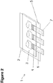
FIG. 2 depicts the device inFIG. 1 in a layered format. -
FIG. 3 shows a schematic sectional view illustrating another device not within the scope of the present invention. -
FIG. 4 depicts the device inFIG. 3 in a layered format. -
FIG. 5 depicts the device ofFIG. 2 as a schematic sectional view from the side. -
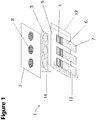
FIG. 6 shows a schematic exploded view illustrating an exemplary embodiment of the device according to the invention; 2: first layer (spotting layer) for applying or receiving blood sample, 3: membrane for separating plasma from whole blood, 4: intermediate layer comprising a double-sided adhesive material for blocking or limiting the distribution of blood, 5: third layer comprising one or more removable absorptive members for collecting the plasma fraction, 6: carrier layer for protecting and stabilizing the device comprising anadhesive material absorptive member 9, and 13: adhesive material to fix and support the device. -
FIG. 7 depicts the embodiment inFIG. 6 as a schematic sectional view from the side. -
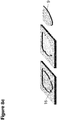
FIG. 8 shows a schematic sectional view where the shield-shaped area comprising the collection material including plasma is within or detached from the exemplary embodiment of the device according to the invention,- (a) shows two types of
absorptive members 9, one including a longitudinally folded planar area, 12, the other one with an unfolded even surface, - (b) shows an embodiment wherein the anchor elements are comprising a blocking element, 14, to avoid leakage of the plasma sample from the collection material,
- (c) shows an absorptive member, 9, comprising a removable absorptive element with anchor elements, 16.
- (a) shows two types of
-
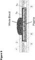
FIG. 9 depicts the embodiment inFIG. 6 with applied whole blood sample as a schematic sectional view from the side. A whole blood sample is applied on the receiving member of the spotting layer. The blood sample is distributed through the opening of the device to the absorptive member comprising a plasma collection material via capillary forces. -
FIG. 10 shows the data in accordance to specimen stability testing over 16 weeks as described in Example 2 (Delta Mean log Titer v. Time point). A delta mean log titer value of the target of less or equal than 0.3 log cp/ml relative to time point zero at the start of the experiment (TP0) was defined as stability requirement. For example TP0-TP3W describes the relative delta mean log titer value after 3 weeks of storage. - Unless defined otherwise, all technical and scientific terms used herein have the same meaning as commonly understood by one of ordinary skill in the art to which this invention pertains. Although essentially any methods and materials similar to those described herein can be used in the practice or testing of the present invention, only exemplary methods and materials are described. For purposes of the present invention, the following terms are defined below.
- The term "plasma separation" refers to separating plasma from a whole blood sample including a partial volume of plasma wherein substances, e.g., substances being characteristic of specific infection such as HIV particles, are detected, and a partial volume of cellular components (hematocrit).
- The term "spotting layer" or "
layer 2" refers to the top layer of the PSC consisting of a suitable film material having a thickness between approximately 100 and 400 µm, preferably between 150 and 250 µm. Suitable materials for preparing the spotting layer are for example polyethylen-terephthalate (PET) or related plastic materials. - The term "receiving member" refers to a first layer (usually the top or spotting layer) comprising one or more "sample receiving portions" or "receiving portions". The sample receiving portions are adapted to permit contact of said blood sample with the separation layer. The sample receiving portion may be an opening, e.g., a substantially circular opening, with a three-dimensional domain that permits application of a blood sample and direct efficient distribution of the blood sample. In one embodiment, the sample receiving portion is a punched-out or laser-cut circular or oval hole. In another embodiment, the height of the side walls of the three-dimensional domain of each receiving portion is between 0, 1 and 0, 5 mm, preferably approximately 0, 15 to 0, 2 mm. The size of each of the sample receiving portions is usually smaller (e.g., approx. 10 mm diameter) than the size of each of the surfaces of the "separating member" or "absorptive member" of the following, the separation layer.
- The term "separating member" refers to a second layer, the separation layer, made up of one or more plasma separation membrane regions allowing the efficient removal of the cellular components of whole blood applied to the openings at the spotting layer. Suitable plasma separation membranes are composed of, e.g., an asymmetric poly-sulfone material as for example membranes like the Vivid™ Membrane (available from Pall Corp., Port Washington, NY/USA). In general, asymmetric membranes having a shiny side and a dull (or rough) side are suitable. The dull side is the top surface, i.e., the surface to which a liquid sample is added. One separation member comprises a top planar shield-shaped surface for filtering plasma from a blood sample added through the sample receiving portion and a bottom planar shield-shaped surface contacting a third layer of the PSC. The shield-shaped surface of the separation members may be stamped, e.g., the frame or border region of the shield-shaped surface is sealed to a membrane resulting in a circular or nearly circular liquid-tight frame suitable to prevent or avoid leakage of liquid samples like blood. Sealing of the frame or border region can be achieved by applying mechanical forces, e.g., by compressing the membrane to approximately 30-40 % of its original thickness, or by treating the surface of the membrane with a laser (the width of the resulting frame or border is 0, 5 to 2,0 mm, preferably 0,8 to 1, 2 mm). Applying thermal mechanical compressing or cutting results in a sealing wherein the width of the frame or border is 2, 0 mm or less, preferably the cutting edge itself is used as a sealing with the consequence there is no frame or border area. The size of an area of the planar shield-shaped surface of one separation member is usually between 100 and 300 mm2, preferably approximately 200 mm2.
- The term "absorptive member" refers to an area on a third layer adapted to the form of the bottom planar surface of the separating members of the second layer. The absorptive member may comprise a removable strip comprising an "absorptive element" having a top planar surface contacting to the bottom planar surface of the separating member and optionally a non-absorptive handle adjacent to the absorptive element. The non-absorptive handle supports removing the absorptive element. The absorptive member takes the form of a shield-shaped area comprising a removable absorptive element having a top planar shield-shaped surface. The absorptive element comprises anchor elements for fixing the removable absorptive element to the third layer. The anchor elements may comprise blocking or sealing elements. For example, hydrophobic or UV-glue treated blocking elements are suitable means to prevent or avoid leakage of liquid samples like plasma. The absorptive element may have a longitudinally folded two-dimensional structure or comprises a longitudinally folded planar area. One advantage of the adsorptive element having a longitudinally planar or two-dimensional structure is that the flow-through efficiency of the sample is increased. Another advantage of the absorptive element having a shield-shaped form and having a longitudinally folded planar or two-dimensional structure is that said element can be easily transferred into tubes for further processing, e.g., incubation and analysis. The absorptive member is preferably composed of a plasma collection fleece or material (e.g., a fleece consisting of cotton linters with an average thickness of 300-420 µm, a fleece used in Whatman™ 903™ paper, a fleece known as FP2992, FP2316 or ISP7216 which are available, e.g., from Hahnemühle GmbH, Dassel/Germany) or a plasma collection material which is not dissolvable in water or buffer containing solutions (e.g., a net, grid or membrane material, commercially available e.g. from Diomics Corp., San Diego, CA/USA, or VWR International).
- The term "backing member" refers to the area of the third layer outside the absorptive member arranged in a manner to support the absorptive members.
- A device for separating plasma from a whole blood sample according to the invention is shown in
Figures 6-10 . - A multi-layer plasma separation card according to the present invention comprises
- (a) a first layer (2) including at least three sample receiving portions (8) comprising (i) a top planar surface framed by a barrier element for applying or receiving a blood sample, said sample receiving portions permitting contact of said blood sample with separating members; and (ii) a bottom planar surface contacting said separating members,
- (b) a second layer (4) including at least three separating members (3), each separating member (3) permitting the passage of plasma to an absorptive member (9) and comprising (i) a top planar surface for receiving said blood sample; and (ii) a bottom planar shield-shaped surface contacting an absorptive member (9), and
- (c) a third layer (5) including at least three absorptive members (9) for absorbing plasma from the bottom planar surface of each corresponding separating member (3) and a backing member (10) arranged in a manner to support said absorptive members (9), each absorptive member (9) comprising a removable absorptive element having a top planar surface being in contact to said bottom planar surface of the separating member (3), said absorptive element being removable fixed to the third layer (5), wherein each of said absorptive element (9) comprises at least two elements for fixing the removable absorptive element with said third layer (5). According to the invention the elements for fixing the removable absorptive elements are anchor elements (16) which may comprise blocking elements (14) to avoid leakage of the plasma sample.
- The bottom planar surface of each separating member (3) preferably comprises a grouted or compressed frame or border to avoid leakage of the blood sample.
- In a preferred embodiment, the multi-layer plasma separation card comprises a plasma level control layer linked to the third layer. The plasma level control layer is either directly in contact with or positioned adjacent to the third layer comprising the removable absorptive element.
- The multi-layer plasma separation card comprises at least three sample receiving portions (8) wherein each of said sample receiving portions is a punched-out circular or oval hole. Preferably, the size of each of the sample receiving portions is smaller (e.g., approx. 10 mm diameter) than the size of each of the shield-shaped surfaces of the separating member or absorptive member (e.g., 200 mm2). In a further embodiment, on each of the
sample receiving portions 10 µl to 1000 µl, preferably 50 µl to 500 µl, more preferably 100 µl of a whole blood sample are applied. In one embodiment, the separating members comprise a plasma separation membrane, preferably an asymmetric plasma separation membrane (e.g., Vivid Membrane). According to the invention is in particular preferred that the at least three absorptive members (9) each comprises a fleece consisting of cotton linters with an average thickness of 300-420 µm. In a further preferred embodiment of the multi-layer plasma separation card, the absorptive member is composed of a plasma collection material (e.g., a fleece consisting of cotton linters with an average thickness of 300-420 µm, a fleece used in Whatman™ 903™ paper, appropriate fleece materials, e.g., FP2992, FP2316 or ISP7216, are available, e.g., from Hahnemühle GmbH, Dassel/Germany) and optionally comprises a plasma stabilizer. In another preferred embodiment, each of the removable absorptive elements comprises a longitudinally folded planar area. In another preferred embodiment, the removable absorptive elements can be easily removed or transferred to a vessel for determination, e.g., with a tweezers. -
FIG. 6 depicts one embodiment of the plasma separation card (PSC) with multiple layers according to the invention. Thefirst layer 2 is for applying or receiving a blood sample (spotting layer). Thefirst layer 2 has a top planar surface for applying or receiving a blood sample and a bottom planar surface adapted to contact a separatingmember 7. Thefirst layer 2 comprises at least threesample receiving portions 8. The blood sample is applied to one or moresample receiving portions 8. The at least threesample receiving portions 8 are adapted to permit contact of said blood sample with at least three separatingmembers 3, e.g., with the impact of capillary forces. For example, each of thesample receiving portions 8 may be an opening (e.g., a substantially circular opening) with a three-dimensional domain in thefirst layer 2 that permits application of a blood sample and direct efficient distribution of the blood sample to a separatingmember 3. In one embodiment, thesample receiving portion 8 is a punched-out circular or oval hole. In another embodiment, the height of the side walls of the three-dimensional domain of each receivingportion 8 is between 0,1 and 0,5 mm, preferably 0,15 to 0,2 mm. - The PSC according to the invention has a
second layer 3 made up of at least three separating members 5 (separation layer). Thesecond layer 4 comprises at least three, four, or five separating members. The separation layer orseparation member 3 comprises a plasma separation membrane allowing the efficient removal of the cellular components of whole blood. Suitable plasma separation membranes constructed of an asymmetric polysulfone material are for example membranes like the Vivid™ Membrane (available from Pall Corp., Port Washington, NY/USA). In one embodiment, the separation layer orseparation member 3 is an asymmetric membrane with two sides. An asymmetric membrane, e.g., the Vivid™ Membrane, has a shiny side and a dull (or rough) side. The dull side is the top surface, i.e., the surface to which a liquid sample will be added. The separation member comprises a top planar shield-shaped surface for filtering plasma from a blood sample added through an opening (e.g., sample receiving portion 8) in thefirst layer 2, and a bottom planar shield-shaped surface being adapted to contact athird layer 5 of the PSC. The area of the planar shield-shaped surface of one separation member is between 100 and 300 mm2, preferably approximately 200 mm2. The size of each of thesample receiving portions 8 is usually smaller (e.g., approx. 10 mm diameter) than the size of each of the surfaces of the separating member or absorptive member (e.g., approx. 200 mm2). - In a further embodiment the edges of the shield-shaped surface of each of the at least three separation members are stamped. In one embodiment the frame or border region of the shield-shaped surface is sealed to a membrane resulting in a circular or nearly circular liquid-tight frame suitable to prevent or avoid leakage of liquid samples like blood. Sealing of the frame or border region can be achieved by applying mechanical forces, e.g., by compressing the membrane to approximately 30-40 % of its original thickness, or by treating the surface of the membrane with a laser (the width of the resulting frame or border is 0, 5 to 2,0 mm, preferably 0,8 to 1, 2 mm). Applying thermal mechanical compressing or cutting results in a sealing wherein the width of the frame or border is 2, 0 mm or less, preferably the cutting edge itself is used as a sealing with the consequence there is no frame or border area.
- The PSC according to the invention further comprises an intermediate layer or
spacer layer 4 between the first layer 2 (spotting layer) and the second layer 3 (separating layer). Saidspacer layer 4 comprises openings adapted to the sample receiving portions of thefirst layer 2 on the one hand and to the separating members of thesecond layer 3 on the other hand. In one embodiment, the openings in thespacer layer 4 are punched-out holes adapted to the form of the planar shield-shaped surface of each of the at least three separating members in thesecond layer 3. Thespacer layer 4, for example, comprises an adhesive material, e.g., a double sided adhesive tape, having a thickness of 0,05 to 0,3 mm, preferably a thickness between 0,1 and 0,2 mm. - The PSC has a
third layer 5 that contains at least threeabsorptive members 9 and abacking member 10 arranged in a manner to support theabsorptive members 9. Eachabsorptive member 9 takes the form of a shield-shaped area or a strip that comprises a removable absorptive element having a top planar shield-shaped surface that is adapted to contact the bottom planar surface of one or more separating members. Each absorptive element comprises at least two anchor elements for fixing the removable absorptive element with thethird layer 5. The removable absorptive element is adapted to avoid or reduce the formation of air bubbles, e.g., the absorptive element has a longitudinally folded two-dimensional structure or comprises a longitudinally folded planar area. A further advantage of the absorptive element having a longitudinally planar or two-dimensional structure is that the flow-through efficiency of the sample is increased. Another advantage of the absorptive element having a shield-shaped form and having a longitudinally folded planar or two-dimensional structure is that said element can be easily transferred into tubes for further processing, e.g., incubation and analysis. - In one particular embodiment, the removable absorptive element of the
absorptive member 9 is composed of a plasma collection fleece or material (e.g., a fleece consisting of cotton linters with an average thickness of 300-420 µm, a fleece used in Whatman™ 903™ paper, appropriate fleece materials, e.g., FP2992, FP2316 or ISP7216 are available, e.g., from Hahnemühle GmbH, Dassel/Germany). In another embodiment, the absorptive element is composed of a plasma collection material which is not dissolvable in water or buffer containing solutions (e.g., a net, grid or membrane material, commercially available e.g. from Diomics Corp., San Diego, CA/USA, or VWR International). In a further embodiment, the absorptive element of theabsorptive member 9 comprises a plasma stabilizer. - In another aspect, the different layers of the plasma separation card are attached with a removable adhesive. The adhesive is a means that allows the detachment of one PSC layer from another layer without causing substantial damage to any of the PSC layers. Each of
FIG. 6 ,7 and9 illustrates an exemplary placement of such adhesives. A removable adhesive is used to attach the bottom planar surface of thefirst layer 2 to the top planar surface of each of the at least three separating members. The removable adhesive is positioned along the outer edges of the bottom planar surface of thefirst layer 2 of the card. The removable adhesive is positioned to superimpose over a separation member. In another embodiment, the removable adhesive comprises openings corresponding to the punched-out holes in thefirst layer 2. In one additional embodiment, a removable adhesive is used to attach the bottom planar surface of each separation member to the top planar surface of eachabsorptive member 9. - The
absorptive member 9 has a perforatedborder 11 which allows it to be removed from thethird layer 5 without damaging the remaining part of thethird layer 5 or anotherabsorptive member 9. - In other embodiments, the perforated
border 11 extends to at least one edge of the third layer 5 (seeFIG. 6 ). - The
absorptive member 9 of the PSC according to the invention comprises an absorptive element adapted to absorb plasma through the bottom planar surface of a separation member driven by the impact of capillary forces. In a preferred embodiment, the absorptive element is composed of a plasma collection material having a sucking capacity of at least 150 g/m2, preferably a sucking capacity of 200-400 g/m2 (e.g., a fleece consisting of cotton linters with an average thickness of 300-420 µm, a fleece used in Whatman™ 903™ paper, a fleece known as FP2992, FP2316 or ISP7216 which are available, e.g., from Hahnemühle GmbH, Dassel/Germany). In other embodiments, the (i) the absorptive element covered on each of theabsorptive members 9, and/or (ii) thethird layer 5 is composed of a plasma collection material (e.g., one of those mentioned above). The absorptive element may further comprise a substance or mixture for stabilizing plasma. - In another embodiment, the
first layer 2 may be made of cardstock with a certain length and width (e.g., same length and width as the first area of the top surface of the third layer 5). -
FIG. 7 and9 each depicts the embodiment of the PSC fromFIG. 6 as a schematic sectional view from the side. - In another aspect, the different layers of the plasma separation card are attached with a removable adhesive material. The adhesive material is one that allows for the detachment of one PSC layer from another without causing substantial damage to any of the PSC layers. The removable absorptive material or element comprises at least two elements for fixing the absorptive element with the third layer. The removable absorptive element comprises at least two anchor elements for fixing said removable absorptive element with the third layer.
-
FIG. 6 illustrates exemplary placements of such a removable adhesive, 4 and 13. A removable adhesive is used to attach the bottom planar surface of thefirst layer 2 to the top planar surface of one ormore separating members 7. The removable adhesive is positioned along the outer edges of the bottom planar surface of thefirst layer 2 of the card. Further, the removable adhesive is positioned to superimpose over aseparation member 7. The removable adhesive comprises holes corresponding to the punched-out holes in thefirst layer 2. In a further embodiment, a removable adhesive is positioned on the fourth layer. Thefourth layer 6 as shown inFIG. 6 serves as carrier supporting and stabilizing the plasma separation card. The removable adhesive is positioned at each of the long edge sides of the support layer orcarrier 6. Thecarrier 6 may consist of a stiff material as for example a strong paper or a film having a thickness of 350 µm and consisting of polyethylen-terephthalate, e.g., HOSTAPHAN® RN350.MED. Alternatively, a coated film with a activatable sticking layer, e.g., a film consisting of a polystyrene with a thickness range of approximately 100-400 µm, e.g., 350 µm, coated with an activatable adhesive or sticking layer may be used. The sticking layer might be thermally activated, e.g., welded by ultrasound or activated by pressure. The carrier might be fixed, wherein the fleece layer is only selectively welded outside the plasma reservoir signs. Thus, the "adhesive stripes 13" are omitted. - In a preferred embodiment, the PSC according to the invention comprises an additional layer, a so-called plasma level control layer, between said
third layer 5 and the carrier or support layer. The plasma level control layer comprising a plasma level control substance is either directly in contact with or positioned adjacent to the removable absorptive material (e.g., fleece) for collecting the plasma fraction. In another embodiment, the support layer (carrier) and the plasma level control layer are both transparent. PH indicators, e.g., Bromothymol Blue, or pH independent water sensitive papers (e.g., commercially available from Quantifoil Instruments GmbH, Jena/Germany) are suitable as plasma level control substances. If a pH indicator is used, the addition of plasma shifts the pH value towards the alkaline area triggering a color change. If a plasma level control layer comprising a water sensitive paper is used, the addition of plasma changes the color of the paper; the result is visible after a few seconds. The plasma level control layer in particular guarantees that enough plasma is present for the test and, further, ensures consistency of test results, given that constant amounts of starting materials are applied. - In a further embodiment of the invention, the
first layer 2 may be made of card stock with a certain length and width (e.g., same length and width as the first area of the top surface of the third layer 5). In one additional embodiment, the top planar surface of thefirst layer 2 comprises one or more circular markings corresponding to eachsample receiving portion 8. - A further object of the invention is a method for preparing the multi-layer plasma separation card, comprising steps (a) preparing a separation member layer, an absorptive member layer comprising a plasma separation fleece, a spotting layer and a layer comprising an adhesive material, (b) combining the layers prepared by sticking the spotting layer onto the adhesive layer in a suitable device, wherein the separation membrane layer is inserted and grouted with the side of the adhesive layer not stuck to the spotting layer or a first layer and subsequently putting the absorptive member layer onto the separation member layer and (c) sticking the composite of the layers onto a carrier support layer in longitudinal direction.
- In one embodiment, the method for preparing the multi-layer plasma separation card, comprises the following steps
- (1) preparing the separation membranes (e.g. an asymmetric membrane prepared from polysulfone, a Vivid™ Membrane) in the desired form of shield-shaped areas, by mechanical punching or laser cutting, compressing with mechanical and/or thermal forces the frame and border region to approximately 1/3 of the original thickness of the membrane resulting in a circular frame with a breath of approximately 1 mm,
- (2) preparing the absorptive member layer comprising a plasma collection fleece on a backing material in the desired form by mechanical punching or laser cutting, wherein the longitudinally folded area or notches are embossed on the plasma collection fleece area with a press. Alternatively, the folding and creasing can be performed by applying ultrasonic or Kiss-cut technologies.
- (3) preparing the spotting layer based on card stock paper with one or more holes or portions for applying blood samples by cutting and/or punching,
- (4) preparing a layer consisting of a double-sided adhesive material comprising holes or openings corresponding to the punched-out holes of the spotting layer (3) and adapted to the form of the one or more separation membranes (1),
- (5) preparing a carrier support layer comprising a double-sided adhesive material positioned at each of the long sides of the support layer, and
- (6) combining the layers obtained by steps (1) to (5) as follows: Sticking the spotting layer derived from step (3) onto the adhesive layer derived from step (4) in a suitable device wherein the separation membrane derived from step (1) is inserted and grouted with the side of the adhesive layer not stuck to the spotting layer and subsequently putting the fleece layer derived from step (2) onto the separation membrane. The composite of the layers derived from steps (1) to (4) is then stuck to a carrier support layer in longitudinal direction.
- The present invention is further directed to a packaging concept for supplying the multi-layer plasma separation card. The packaging concept may further comprise an impermeable, moisture-resistant, chemically inert bag, e.g. prepared from aluminum foil or aluminum coated plastic film, comprising the multi-layer separation card and a drying agent or a desiccant (single-card packaging). The bag with a size essentially adapted to the size of the multi-layer plasma separation card comprising the plasma separation card and, e.g., the desiccant is usually hermetically sealed until it is opened for use. In an advantageous embodiment, the packaging concept further comprises a second impermeable, chemically inert closable bag for inserting and transporting the multi-layer plasma separation after use (that means including plasma sample(s)) and optionally means for taking of blood samples. Suitable means for taking blood samples are for example disposables like lancets. The shelf life of the unused multi-layer separation card provided with the packaging concept is at least 24 months, at a temperature of 18-45° C and a relative humidity up to 85%. The plasma sample situated on the multi-layer separation card contained in a closed impermeable, chemically inert bag is stable for at least 12 weeks, at a temperature of 18-45° C and a relative humidity up to 85%.
- Another object of the invention is a method for detecting HIV, HCV and/or HBV in a plasma sample comprising using a multi-layer plasma separation card according to the invention.
- The
spotting Layer 2 consists of a 350 µm thick film made from stiff polyethylen-terephthalate (PET) material, commercially available as HOSTAPHAN® RN350.MED. From the material, usually supplied on rolls, multiple strips are cut in size of approximately 85 × 30mm. Threeholes 8 are cut out with a punch. Thespacer 4 is made of a double-sided tape, e.g., tesafix 51570 or tesafix 4959 (commercially available from Tesa SE, Hamburg/Germany), having a thickness of ca. 0, 1 mm, which is protected on both sides with a removable film. Multiple strips are cut out from the material supplied on rolls, wherein each strip is approximately 85 × 30 mm in size. - The three shield-formed openings are cut out with a laser. As
membrane 3 has been used Vivid membrane GR (8 "×11" sheet with a thickness of 0.3 mm; Pall Corp., Port Washington, NY/USA). Shield-shaped parts having an approximate size of 17 × 21 mm are punched out of a fleece 5 (e.g., cotton linters having an average thickness of 300 ― 420 µm and a sucking capacity of 235 ― 290 g/m2), 7a. Theedge 7b may be 1-2 mm wide and is pressed with a press to 0.1 mm. A comparable result can also be reached with laser or ultrasound means. As fleece material cotton linters, e.g., comprising a small amount of a polyamide-epichlorohydrin resin, having an average thickness of 300-420 µm and a sucking capacity of 235-290 g/m2 was used. Other fleece materials having a thickness of 300-450 µm and a sucking capacity of 200-400 g/m2 (e.g., FP2992, FP2316 or ISP7216 fleece, e.g., commercially available from Hahnemühle GmbH, Dassel/Germany) can also be used.Multiple strips 10 with a size of approximately 85 × 30 mm were cut out the fleece material available in rolls. - Three
spots 9 were produced from each of these stripes by using a laser. This step can also be performed by using a mechanical punch. Thenotches 12 are embossed on the shield-formedarea 9 with a press. This step can also be performed by using a laser, ultrasonic, or kiss-cut technologies. Thecarrier 6 may consist of a film having a thickness of 350 µm and consisting of polyethylen-terephthalate, e.g., HOSTAPHAN® RN350.MED. Cards of a size of approximately 85 × 53mm are cut of the film material. In some embodiments, two double-sidedadhesive stripes 13 might be adhered on the carrier cards in the longitudinal direction. - For the following steps means and devices for ensuring an accurate set-up are used. The protection film is removed from the double-sided
adhesive material 4. The adhesive material was then applied flush fitting to thespotting layer 2. The second protection film was removed from the double-sidedadhesive material 4, and the composition consisting of thespotting layer 2 and thespacer 4 were inserted into a device. - The Vivid membrane is inserted into a further device and glued or fixed on the
spacer layer 4 linked to thespotting layer 2. This process has been repeated three times until all three spots were made. The layer comprising theplasma collection fleece 5 is inserted into a still further device and glued by pick and place on the Vivid membrane layer of the composition consisting of spotting layer, spacer layer and the Vivid membrane. The protection film is removed from the adhesive tape(s) 13 and the composition consisting of the spotting layer, the spacer layer, the Vivid membrane and the plasma collection fleece is applied flush to the top of thecarrier 6. -
- 1) An amount of whole blood (∼100ul) is applied onto one of the receiving members of the Plasma Separation Card (Spotting Layer).
- 2) The card is dried for 3-4 hours at room temperature.
- 3) After drying, the spotting layer with the attached membrane is peeled from the carrier. Tweezers are used to remove the one or more plasma filled shield-sharped areas (
member 9 inFIG. 8a-c ) and to transfer it/them into an appropriate sample tube(s). - 4) 1100 µl of a Specimen Pre-Extraction (SPEX) buffer reagent is added to one tube each and the sample(s) is (are) incubated at 56°C for 10-20 minutes with shaking at 1000 rpm.
- 5) Transfer of the tube(s) including the plasma sample(s) onto the instrument.
- 6) Starting of workflow on the instrument and measured.
- In Table 1 the estimated Limit of Detection of the PSC in combination with the COBAS® AmpliPrep/COBAS® TaqMan® HIV Test, v2.0 and the CAP/CTM System and estimated Limit of Detection of the PSC in combination with the cobas 4800 HIV Test and the cobas® 4800 system is shown. The Limit of Detection and the corresponding confidence interval were calculated with 95% by using an established statistical method (Probit Analysis).
Table 1: Limit of Detection Platform Sample HIV HBV HCV c4800 Spiked Whole Blood 613 cp/ml (CI: 601-1696) 148 IU/ml (CI: 75-958) 467 IU/ml (CI: 260 -2355) CAP/CTM Spiked Whole Blood 502 cp/ml (CI: 340-1084) 188 IU/ml (CI: 108-793) N/A CI: Confidence Interval 95% - In Table 2 the estimated linearity of the PSC in combination with the cobas® HIV and the cobas® 6800/8800 system and the COBAS® AmpliPrep/COBAS® TaqMan® HIV Test, v2.0 and the CAP/CTM System is shown. Linearity was assessed using the predominant genotype HIV-1 Group M Subtype B in whole blood. The linearity panel was prepared as a serial dilution of a high titer cell culture supernatant covering the intended linear range. The resulting data were analyzed to identify the linear range according to Clinical and Laboratory Standard Institute (CLSI) guideline EP6-A. The linear range and the R2 value were calculated.
Table 2: Linearity Platform HIV1 Concentration Levels Sample Linear Range CAP/CTM 200 cp/ml HIV Spiked Whole Blood Linearity is given over the range 400 - 2E+07 cp/ml 400 cp/ml 1.0E3 cp/ml 1.0E4 cp/ml 1.0E5 cp/ml R2=0.98 1.0E7 cp/ml 2.0E7 cp/ml c6800 200 cp/ml HIV Spiked Whole Blood Linearity is given over the range 1000 - 2E+07 cp/ml 400 cp/ml 1.0E3 cp/ml 1.0E4 cp/ml 1.0E5 cp/ml 1.0E7 cp/ml R2=0.99 2.0E7 cp/ml - In the diagram presented in
FIG. 10 the data in accordance to specimen stability testing over 16 weeks is shown. A concentration of 1200 cp/ml was tested over a time period of 16 weeks at an elevated temperature of 40°C and a relative humidity of 10-40%. A delta mean log titer value of the target of less or equal than 0.3 log cp/ml relative to time point zero at the start of the experiment (TP0) was defined as stability requirement. For example, TP0-TP3W describes the relative delta mean log titer value after 3 weeks of storage und the described conditions. Data with and without stabilizer is shown.
Claims (14)
- A multi-layer plasma separation card comprising:(a) a first layer (2) including at least three sample receiving portions (8) comprising (i) a top planar surface for applying or receiving a blood sample, said sample receiving portions (8) permitting contact of said blood sample with separating members; and (ii) a bottom planar surface contacting said separating members,(b) a second layer (4) including at least three separating members (3), each separating member (3) permitting the passage of plasma to an absorptive member (9) and comprising (i) a top planar surface for receiving said blood sample; and (ii) a bottom planar shield-shaped surface contacting an absorptive member (9), and(c) a third layer (5) including at least three absorptive members (9) for absorbing plasma from the bottom planar surface of each corresponding separating member (3) and a backing member (10) arranged in a manner to support said absorptive members (9), each absorptive member (9) comprising a removable absorptive element having a top planar surface being in contact to said bottom planar surface of the separating member (3), said absorptive element being detachable fixed to the third layer (5),characterized in that each of said removable absorptive element (9) comprises at least two anchor elements (16) for fixing the removable absorptive element with the third layer (5).
- The multi-layer plasma separation card according to claim 1, wherein said bottom planar surface of each separating member (3) comprises a grouted or compressed frame or border (7b) to avoid leakage of the blood sample.
- The multi-layer plasma separation card according to any of the preceding claims, wherein said anchor elements (16) of the absorptive elements (9) comprise blocking elements (14) to avoid leakage of the plasma sample.
- The multi-layer plasma separation card according to any of the preceding claims, comprising an additional layer comprising a plasma level control substance, wherein said additional layer being either directly in contact with or positioned adjacent to the third layer (5) comprising the removable absorptive element.
- The multi-layer plasma separation card according to any of the preceding claims, wherein the size of each of the sample receiving portions (8) is smaller than the size of each of the surfaces of the separating member (3) or absorptive member (9).
- The multi-layer plasma separation card according to any of the preceding claims, wherein on each of the sample receiving portions (8) 10 µl to 1000 µl of a whole blood sample is applied.
- The multi-layer plasma separation card according to any of the preceding claims, wherein the separating member (3) comprises an asymmetric plasma separation membrane.
- The multi-layer plasma separation card according to any of the preceding claims, wherein the absorptive member (9) is composed of a plasma collection material and optionally comprises a plasma stabilizer.
- The multi-layer plasma separation card according to any of the preceding claims, wherein the absorptive member (9) comprises a fleece consisting of cotton linters with an average thickness of 300-420 µm.
- The multi-layer plasma separation card according to any of the preceding claims, wherein each of the removable absorptive elements (9) comprises a longitudinally folded planar formation (12).
- The multi-layer plasma separation card according to any of the preceding claims, wherein the removable absorptive elements (9) can be easily removed and/or transferred to a vessel for determination with a tweezers.
- A method for preparing a multi-layer plasma separation card according to any of claims 1-11, comprising the following steps (a) preparing a separation member layer (3), an absorptive member layer (9) comprising a plasma separation fleece, a spotting layer (2) and a layer comprising an adhesive material (13), (b) combining the layers prepared by sticking the spotting layer (2) onto the adhesive layer (13) in a suitable device wherein the separation membrane layer (3) is inserted and grouted with the side of the adhesive layer (13) not stuck to the spotting or first layer (2) and subsequently putting the absorptive member layer (9) onto the separation member layer (3) and (c) sticking the composite of the layers onto a carrier support layer (6) in longitudinal direction.
- A method for detecting HIV, HCV and/or HBV in a plasma sample comprising using the multi-layer plasma separation card according to any of claims 1-11.
- A packaging concept comprising a multi-layer plasma separation card according to any of claims 1-11 and a desiccant material in a hermetically sealed environment.
Applications Claiming Priority (3)
| Application Number | Priority Date | Filing Date | Title |
|---|---|---|---|
| US201562141089P | 2015-03-31 | 2015-03-31 | |
| EP16155284 | 2016-02-11 | ||
| PCT/EP2016/056888 WO2016156376A1 (en) | 2015-03-31 | 2016-03-30 | Plasma separation card |
Publications (2)
| Publication Number | Publication Date |
|---|---|
| EP3278105A1 EP3278105A1 (en) | 2018-02-07 |
| EP3278105B1 true EP3278105B1 (en) | 2021-11-17 |
Family
ID=55398193
Family Applications (1)
| Application Number | Title | Priority Date | Filing Date |
|---|---|---|---|
| EP16715818.7A Active EP3278105B1 (en) | 2015-03-31 | 2016-03-30 | Plasma separation card |
Country Status (6)
| Country | Link |
|---|---|
| US (2) | US10663379B2 (en) |
| EP (1) | EP3278105B1 (en) |
| JP (1) | JP6787920B2 (en) |
| CN (1) | CN107430114B (en) |
| ES (1) | ES2903175T3 (en) |
| WO (1) | WO2016156376A1 (en) |
Families Citing this family (14)
| Publication number | Priority date | Publication date | Assignee | Title |
|---|---|---|---|---|
| EP3754011B1 (en) | 2015-09-09 | 2022-02-16 | Drawbridge Health, Inc. | Devices for sample collection, stabilization and preservation |
| CN111220431A (en) * | 2016-10-26 | 2020-06-02 | 上海万承生物科技有限公司 | Method for detecting active components in blood plasma and blood plasma card using same |
| CN115251923A (en) | 2017-01-10 | 2022-11-01 | 集联健康有限公司 | Devices, systems, and methods for sample collection |
| FR3065284B1 (en) | 2017-04-18 | 2019-06-14 | Ahlstrom-Munksjo Oyj | NEW PLASMA COLLECTION CARD FROM A BLOOD SAMPLE |
| CN112689762B (en) | 2018-06-01 | 2024-08-23 | 美国控股实验室公司 | Methods and systems for LC-MS/MS proteomics genotyping |
| FR3092397B1 (en) * | 2019-02-01 | 2024-05-03 | Munksjoe Ahlstrom Oyj | DEVICE FOR COLLECTION, PRESERVATION AND STORAGE OF EUKARYOTIC CELLS CONTAINED IN A SAMPLE OF BIOLOGICAL FLUID FOR SUBSEQUENT CELLULAR ANALYSIS |
| EP3753634B1 (en) * | 2019-06-19 | 2021-08-04 | Euroimmun Medizinische Labordiagnostika AG | Sample carrier for receiving dried blood components and method for obtaining a membrane element with dried blood components |
| DK180849B1 (en) * | 2019-12-31 | 2022-05-17 | Qlife Aps | Method and device for analysis of liquid samples |
| EP4121733A4 (en) * | 2020-03-18 | 2024-05-22 | Drawbridge Health, Inc. | Systems and methods for sample collection |
| GB2597941A (en) * | 2020-08-10 | 2022-02-16 | Landergren Ulf | Sampling device |
| CN116438435A (en) * | 2020-11-25 | 2023-07-14 | 株式会社普欧威盖特 | Medium for separating and storing plasma or serum, method for producing same, device, kit, and method for measuring glycated protein |
| AU2023310361B2 (en) * | 2022-07-19 | 2025-11-27 | Hylid Diagnostics Inc. | Point-of-care blood analysis system |
| US12140534B2 (en) | 2023-01-05 | 2024-11-12 | Sequitur Health Corp. | Devices, methods, and systems for deriving a permeate from a feed solution |
| US12030045B1 (en) | 2023-01-05 | 2024-07-09 | Sequitur Health Corp. | Devices, methods, and systems for deriving ammonia gas from whole blood |
Family Cites Families (15)
| Publication number | Priority date | Publication date | Assignee | Title |
|---|---|---|---|---|
| JP3299330B2 (en) * | 1993-03-18 | 2002-07-08 | 持田製薬株式会社 | Simple measuring device and method |
| US5516487A (en) * | 1994-06-22 | 1996-05-14 | Isolab, Inc. | Absorbent paper for liquid sampling and impregnated paper calibrators and controls |
| US5948687A (en) * | 1996-06-05 | 1999-09-07 | Cleator; Iain G.M. | Device and method for screening fecal occult blood specimens |
| AUPO087196A0 (en) | 1996-07-05 | 1996-08-01 | Belclan Pty. Limited | Blood separation module |
| US6106732A (en) * | 1998-04-16 | 2000-08-22 | Binax Services, Inc. | Integral blood plasma or serum isolation, metering and transport device |
| US6319719B1 (en) | 1999-10-28 | 2001-11-20 | Roche Diagnostics Corporation | Capillary hematocrit separation structure and method |
| JP2004294388A (en) * | 2003-03-10 | 2004-10-21 | Arkray Inc | Component-analyzing apparatus |
| US7625721B2 (en) * | 2004-02-03 | 2009-12-01 | Polymer Technology Systems, Inc. | Non-precipitating bodily fluid analysis system |
| EP2387714B1 (en) * | 2009-01-23 | 2018-03-14 | Polymer Technology Systems, Inc. | Diagnostic multi-layer dry phase test strip with integrated biosensors |
| EP2375249B1 (en) * | 2010-04-09 | 2019-12-25 | F. Hoffmann-La Roche AG | Devices and process for separating plasma from a blood sample |
| MX2013011196A (en) * | 2011-04-22 | 2013-12-16 | Polymer Technology Systems Inc | Blood separation system and method for a dry test strip. |
| KR101952957B1 (en) | 2012-06-20 | 2019-02-28 | 주식회사 미코바이오메드 | Sensor strip |
| ES2777220T3 (en) | 2013-08-16 | 2020-08-04 | Global Life Sciences Solutions Operations UK Ltd | Methods and compositions for nucleic acid extraction and storage |
| WO2016025726A1 (en) | 2014-08-13 | 2016-02-18 | Vivebio, Llc | An analytic membrane array, and plasma separation device incorporating the same |
| ES2809600T3 (en) | 2014-11-14 | 2021-03-04 | Axxin Pty Ltd | Biological sample collection and storage set |
-
2016
- 2016-03-30 CN CN201680019425.4A patent/CN107430114B/en active Active
- 2016-03-30 WO PCT/EP2016/056888 patent/WO2016156376A1/en not_active Ceased
- 2016-03-30 ES ES16715818T patent/ES2903175T3/en active Active
- 2016-03-30 JP JP2017550670A patent/JP6787920B2/en active Active
- 2016-03-30 EP EP16715818.7A patent/EP3278105B1/en active Active
- 2016-03-30 US US15/085,882 patent/US10663379B2/en active Active
-
2020
- 2020-04-08 US US16/843,130 patent/US11353382B2/en active Active
Non-Patent Citations (1)
| Title |
|---|
| None * |
Also Published As
| Publication number | Publication date |
|---|---|
| US11353382B2 (en) | 2022-06-07 |
| JP2018513363A (en) | 2018-05-24 |
| CN107430114A (en) | 2017-12-01 |
| US10663379B2 (en) | 2020-05-26 |
| CN107430114B (en) | 2020-07-24 |
| WO2016156376A1 (en) | 2016-10-06 |
| ES2903175T3 (en) | 2022-03-31 |
| US20160290901A1 (en) | 2016-10-06 |
| EP3278105A1 (en) | 2018-02-07 |
| JP6787920B2 (en) | 2020-11-18 |
| US20200232892A1 (en) | 2020-07-23 |
Similar Documents
| Publication | Publication Date | Title |
|---|---|---|
| US11353382B2 (en) | Plasma separation card | |
| US6036659A (en) | Collection device for biological samples and methods of use | |
| EP2375249B1 (en) | Devices and process for separating plasma from a blood sample | |
| AU734423B2 (en) | Article for collecting and transporting a sample to be analyzed and procedure for determining an analyte | |
| US20080286150A1 (en) | Fluid Separator Collection Card | |
| EP3420334A1 (en) | Multilayer device for separating blood components and uses thereof | |
| US20230081694A1 (en) | Articles and methods for blood separation | |
| AU2021236560A1 (en) | Multiple path sample collection card | |
| JPH10132800A (en) | Sample protection container integrated with body fluid separation sheet | |
| CN109580489A (en) | The chip and method of blood glucose and blood lipid are detected simultaneously | |
| JPH10104226A (en) | Blood specimen collecting card | |
| JP2015525890A (en) | Matrix and system for storing biological specimens for qualitative and quantitative analysis | |
| JP3285451B2 (en) | Analysis method and analysis element for whole blood sample | |
| US12097493B2 (en) | Kit including planar sample carrier with absorbent membrane layer and box | |
| JPWO2003021255A1 (en) | Blood test equipment | |
| US20250235801A1 (en) | Kits, articles, and methods for blood separation | |
| CN101862564A (en) | A micro blood sample pretreatment system and its preparation process | |
| CZ327595A3 (en) | Apparatus and set for sampling blood | |
| JPH09178741A (en) | Aids detection device andtest kit | |
| JP3175373B2 (en) | Method for measuring enzyme activity | |
| WO2025038491A1 (en) | Systems and methods for analysis of biological fluids | |
| WO2020032270A1 (en) | Dried blood sample-preservation base material | |
| AU2017203286A1 (en) | Method of processing a fluid sample using a fluid separator multi-layer device |
Legal Events
| Date | Code | Title | Description |
|---|---|---|---|
| STAA | Information on the status of an ep patent application or granted ep patent |
Free format text: STATUS: THE INTERNATIONAL PUBLICATION HAS BEEN MADE |
|
| PUAI | Public reference made under article 153(3) epc to a published international application that has entered the european phase |
Free format text: ORIGINAL CODE: 0009012 |
|
| STAA | Information on the status of an ep patent application or granted ep patent |
Free format text: STATUS: REQUEST FOR EXAMINATION WAS MADE |
|
| 17P | Request for examination filed |
Effective date: 20171102 |
|
| AK | Designated contracting states |
Kind code of ref document: A1 Designated state(s): AL AT BE BG CH CY CZ DE DK EE ES FI FR GB GR HR HU IE IS IT LI LT LU LV MC MK MT NL NO PL PT RO RS SE SI SK SM TR |
|
| AX | Request for extension of the european patent |
Extension state: BA ME |
|
| DAV | Request for validation of the european patent (deleted) | ||
| DAX | Request for extension of the european patent (deleted) | ||
| STAA | Information on the status of an ep patent application or granted ep patent |
Free format text: STATUS: EXAMINATION IS IN PROGRESS |
|
| 17Q | First examination report despatched |
Effective date: 20180711 |
|
| GRAP | Despatch of communication of intention to grant a patent |
Free format text: ORIGINAL CODE: EPIDOSNIGR1 |
|
| STAA | Information on the status of an ep patent application or granted ep patent |
Free format text: STATUS: GRANT OF PATENT IS INTENDED |
|
| INTG | Intention to grant announced |
Effective date: 20210617 |
|
| GRAS | Grant fee paid |
Free format text: ORIGINAL CODE: EPIDOSNIGR3 |
|
| GRAA | (expected) grant |
Free format text: ORIGINAL CODE: 0009210 |
|
| STAA | Information on the status of an ep patent application or granted ep patent |
Free format text: STATUS: THE PATENT HAS BEEN GRANTED |
|
| AK | Designated contracting states |
Kind code of ref document: B1 Designated state(s): AL AT BE BG CH CY CZ DE DK EE ES FI FR GB GR HR HU IE IS IT LI LT LU LV MC MK MT NL NO PL PT RO RS SE SI SK SM TR |
|
| REG | Reference to a national code |
Ref country code: GB Ref legal event code: FG4D |
|
| REG | Reference to a national code |
Ref country code: IE Ref legal event code: FG4D |
|
| REG | Reference to a national code |
Ref country code: DE Ref legal event code: R096 Ref document number: 602016066289 Country of ref document: DE |
|
| REG | Reference to a national code |
Ref country code: AT Ref legal event code: REF Ref document number: 1448456 Country of ref document: AT Kind code of ref document: T Effective date: 20211215 |
|
| REG | Reference to a national code |
Ref country code: LT Ref legal event code: MG9D |
|
| REG | Reference to a national code |
Ref country code: NL Ref legal event code: MP Effective date: 20211117 |
|
| REG | Reference to a national code |
Ref country code: ES Ref legal event code: FG2A Ref document number: 2903175 Country of ref document: ES Kind code of ref document: T3 Effective date: 20220331 |
|
| REG | Reference to a national code |
Ref country code: AT Ref legal event code: MK05 Ref document number: 1448456 Country of ref document: AT Kind code of ref document: T Effective date: 20211117 |
|
| PG25 | Lapsed in a contracting state [announced via postgrant information from national office to epo] |
Ref country code: RS Free format text: LAPSE BECAUSE OF FAILURE TO SUBMIT A TRANSLATION OF THE DESCRIPTION OR TO PAY THE FEE WITHIN THE PRESCRIBED TIME-LIMIT Effective date: 20211117 Ref country code: LT Free format text: LAPSE BECAUSE OF FAILURE TO SUBMIT A TRANSLATION OF THE DESCRIPTION OR TO PAY THE FEE WITHIN THE PRESCRIBED TIME-LIMIT Effective date: 20211117 Ref country code: FI Free format text: LAPSE BECAUSE OF FAILURE TO SUBMIT A TRANSLATION OF THE DESCRIPTION OR TO PAY THE FEE WITHIN THE PRESCRIBED TIME-LIMIT Effective date: 20211117 Ref country code: BG Free format text: LAPSE BECAUSE OF FAILURE TO SUBMIT A TRANSLATION OF THE DESCRIPTION OR TO PAY THE FEE WITHIN THE PRESCRIBED TIME-LIMIT Effective date: 20220217 Ref country code: AT Free format text: LAPSE BECAUSE OF FAILURE TO SUBMIT A TRANSLATION OF THE DESCRIPTION OR TO PAY THE FEE WITHIN THE PRESCRIBED TIME-LIMIT Effective date: 20211117 |
|
| PG25 | Lapsed in a contracting state [announced via postgrant information from national office to epo] |
Ref country code: IS Free format text: LAPSE BECAUSE OF FAILURE TO SUBMIT A TRANSLATION OF THE DESCRIPTION OR TO PAY THE FEE WITHIN THE PRESCRIBED TIME-LIMIT Effective date: 20220317 Ref country code: SE Free format text: LAPSE BECAUSE OF FAILURE TO SUBMIT A TRANSLATION OF THE DESCRIPTION OR TO PAY THE FEE WITHIN THE PRESCRIBED TIME-LIMIT Effective date: 20211117 Ref country code: PT Free format text: LAPSE BECAUSE OF FAILURE TO SUBMIT A TRANSLATION OF THE DESCRIPTION OR TO PAY THE FEE WITHIN THE PRESCRIBED TIME-LIMIT Effective date: 20220317 Ref country code: PL Free format text: LAPSE BECAUSE OF FAILURE TO SUBMIT A TRANSLATION OF THE DESCRIPTION OR TO PAY THE FEE WITHIN THE PRESCRIBED TIME-LIMIT Effective date: 20211117 Ref country code: NO Free format text: LAPSE BECAUSE OF FAILURE TO SUBMIT A TRANSLATION OF THE DESCRIPTION OR TO PAY THE FEE WITHIN THE PRESCRIBED TIME-LIMIT Effective date: 20220217 Ref country code: NL Free format text: LAPSE BECAUSE OF FAILURE TO SUBMIT A TRANSLATION OF THE DESCRIPTION OR TO PAY THE FEE WITHIN THE PRESCRIBED TIME-LIMIT Effective date: 20211117 Ref country code: LV Free format text: LAPSE BECAUSE OF FAILURE TO SUBMIT A TRANSLATION OF THE DESCRIPTION OR TO PAY THE FEE WITHIN THE PRESCRIBED TIME-LIMIT Effective date: 20211117 Ref country code: HR Free format text: LAPSE BECAUSE OF FAILURE TO SUBMIT A TRANSLATION OF THE DESCRIPTION OR TO PAY THE FEE WITHIN THE PRESCRIBED TIME-LIMIT Effective date: 20211117 Ref country code: GR Free format text: LAPSE BECAUSE OF FAILURE TO SUBMIT A TRANSLATION OF THE DESCRIPTION OR TO PAY THE FEE WITHIN THE PRESCRIBED TIME-LIMIT Effective date: 20220218 |
|
| PG25 | Lapsed in a contracting state [announced via postgrant information from national office to epo] |
Ref country code: SM Free format text: LAPSE BECAUSE OF FAILURE TO SUBMIT A TRANSLATION OF THE DESCRIPTION OR TO PAY THE FEE WITHIN THE PRESCRIBED TIME-LIMIT Effective date: 20211117 Ref country code: SK Free format text: LAPSE BECAUSE OF FAILURE TO SUBMIT A TRANSLATION OF THE DESCRIPTION OR TO PAY THE FEE WITHIN THE PRESCRIBED TIME-LIMIT Effective date: 20211117 Ref country code: RO Free format text: LAPSE BECAUSE OF FAILURE TO SUBMIT A TRANSLATION OF THE DESCRIPTION OR TO PAY THE FEE WITHIN THE PRESCRIBED TIME-LIMIT Effective date: 20211117 Ref country code: EE Free format text: LAPSE BECAUSE OF FAILURE TO SUBMIT A TRANSLATION OF THE DESCRIPTION OR TO PAY THE FEE WITHIN THE PRESCRIBED TIME-LIMIT Effective date: 20211117 Ref country code: DK Free format text: LAPSE BECAUSE OF FAILURE TO SUBMIT A TRANSLATION OF THE DESCRIPTION OR TO PAY THE FEE WITHIN THE PRESCRIBED TIME-LIMIT Effective date: 20211117 Ref country code: CZ Free format text: LAPSE BECAUSE OF FAILURE TO SUBMIT A TRANSLATION OF THE DESCRIPTION OR TO PAY THE FEE WITHIN THE PRESCRIBED TIME-LIMIT Effective date: 20211117 |
|
| REG | Reference to a national code |
Ref country code: DE Ref legal event code: R097 Ref document number: 602016066289 Country of ref document: DE |
|
| PLBE | No opposition filed within time limit |
Free format text: ORIGINAL CODE: 0009261 |
|
| STAA | Information on the status of an ep patent application or granted ep patent |
Free format text: STATUS: NO OPPOSITION FILED WITHIN TIME LIMIT |
|
| 26N | No opposition filed |
Effective date: 20220818 |
|
| PG25 | Lapsed in a contracting state [announced via postgrant information from national office to epo] |
Ref country code: MC Free format text: LAPSE BECAUSE OF FAILURE TO SUBMIT A TRANSLATION OF THE DESCRIPTION OR TO PAY THE FEE WITHIN THE PRESCRIBED TIME-LIMIT Effective date: 20211117 Ref country code: AL Free format text: LAPSE BECAUSE OF FAILURE TO SUBMIT A TRANSLATION OF THE DESCRIPTION OR TO PAY THE FEE WITHIN THE PRESCRIBED TIME-LIMIT Effective date: 20211117 |
|
| PG25 | Lapsed in a contracting state [announced via postgrant information from national office to epo] |
Ref country code: SI Free format text: LAPSE BECAUSE OF FAILURE TO SUBMIT A TRANSLATION OF THE DESCRIPTION OR TO PAY THE FEE WITHIN THE PRESCRIBED TIME-LIMIT Effective date: 20211117 |
|
| REG | Reference to a national code |
Ref country code: BE Ref legal event code: MM Effective date: 20220331 |
|
| PG25 | Lapsed in a contracting state [announced via postgrant information from national office to epo] |
Ref country code: LU Free format text: LAPSE BECAUSE OF NON-PAYMENT OF DUE FEES Effective date: 20220330 Ref country code: IE Free format text: LAPSE BECAUSE OF NON-PAYMENT OF DUE FEES Effective date: 20220330 |
|
| PG25 | Lapsed in a contracting state [announced via postgrant information from national office to epo] |
Ref country code: BE Free format text: LAPSE BECAUSE OF NON-PAYMENT OF DUE FEES Effective date: 20220331 |
|
| PG25 | Lapsed in a contracting state [announced via postgrant information from national office to epo] |
Ref country code: HU Free format text: LAPSE BECAUSE OF FAILURE TO SUBMIT A TRANSLATION OF THE DESCRIPTION OR TO PAY THE FEE WITHIN THE PRESCRIBED TIME-LIMIT; INVALID AB INITIO Effective date: 20160330 |
|
| PG25 | Lapsed in a contracting state [announced via postgrant information from national office to epo] |
Ref country code: MK Free format text: LAPSE BECAUSE OF FAILURE TO SUBMIT A TRANSLATION OF THE DESCRIPTION OR TO PAY THE FEE WITHIN THE PRESCRIBED TIME-LIMIT Effective date: 20211117 Ref country code: CY Free format text: LAPSE BECAUSE OF FAILURE TO SUBMIT A TRANSLATION OF THE DESCRIPTION OR TO PAY THE FEE WITHIN THE PRESCRIBED TIME-LIMIT Effective date: 20211117 |
|
| PG25 | Lapsed in a contracting state [announced via postgrant information from national office to epo] |
Ref country code: MT Free format text: LAPSE BECAUSE OF FAILURE TO SUBMIT A TRANSLATION OF THE DESCRIPTION OR TO PAY THE FEE WITHIN THE PRESCRIBED TIME-LIMIT Effective date: 20211117 |
|
| PGFP | Annual fee paid to national office [announced via postgrant information from national office to epo] |
Ref country code: ES Payment date: 20250401 Year of fee payment: 10 |
|
| PGFP | Annual fee paid to national office [announced via postgrant information from national office to epo] |
Ref country code: CH Payment date: 20250401 Year of fee payment: 10 |
|
| PG25 | Lapsed in a contracting state [announced via postgrant information from national office to epo] |
Ref country code: TR Free format text: LAPSE BECAUSE OF FAILURE TO SUBMIT A TRANSLATION OF THE DESCRIPTION OR TO PAY THE FEE WITHIN THE PRESCRIBED TIME-LIMIT Effective date: 20211117 |
|
| REG | Reference to a national code |
Ref country code: CH Ref legal event code: U11 Free format text: ST27 STATUS EVENT CODE: U-0-0-U10-U11 (AS PROVIDED BY THE NATIONAL OFFICE) Effective date: 20260401 |
|
| PGFP | Annual fee paid to national office [announced via postgrant information from national office to epo] |
Ref country code: GB Payment date: 20260220 Year of fee payment: 11 |
|
| PGFP | Annual fee paid to national office [announced via postgrant information from national office to epo] |
Ref country code: DE Payment date: 20260219 Year of fee payment: 11 |
|
| PGFP | Annual fee paid to national office [announced via postgrant information from national office to epo] |
Ref country code: IT Payment date: 20260219 Year of fee payment: 11 |
|
| PGFP | Annual fee paid to national office [announced via postgrant information from national office to epo] |
Ref country code: FR Payment date: 20260220 Year of fee payment: 11 |