EP3277613B1 - Controlling the speed of a stairlift - Google Patents
Controlling the speed of a stairlift Download PDFInfo
- Publication number
- EP3277613B1 EP3277613B1 EP16715041.6A EP16715041A EP3277613B1 EP 3277613 B1 EP3277613 B1 EP 3277613B1 EP 16715041 A EP16715041 A EP 16715041A EP 3277613 B1 EP3277613 B1 EP 3277613B1
- Authority
- EP
- European Patent Office
- Prior art keywords
- carriage
- speed
- rail
- chair
- stairlift
- Prior art date
- Legal status (The legal status is an assumption and is not a legal conclusion. Google has not performed a legal analysis and makes no representation as to the accuracy of the status listed.)
- Active
Links
Images


Classifications
-
- B—PERFORMING OPERATIONS; TRANSPORTING
- B66—HOISTING; LIFTING; HAULING
- B66B—ELEVATORS; ESCALATORS OR MOVING WALKWAYS
- B66B9/00—Kinds or types of lifts in, or associated with, buildings or other structures
- B66B9/06—Kinds or types of lifts in, or associated with, buildings or other structures inclined, e.g. serving blast furnaces
- B66B9/08—Kinds or types of lifts in, or associated with, buildings or other structures inclined, e.g. serving blast furnaces associated with stairways, e.g. for transporting disabled persons
- B66B9/0838—Levelling gears
-
- B—PERFORMING OPERATIONS; TRANSPORTING
- B66—HOISTING; LIFTING; HAULING
- B66B—ELEVATORS; ESCALATORS OR MOVING WALKWAYS
- B66B9/00—Kinds or types of lifts in, or associated with, buildings or other structures
- B66B9/06—Kinds or types of lifts in, or associated with, buildings or other structures inclined, e.g. serving blast furnaces
- B66B9/08—Kinds or types of lifts in, or associated with, buildings or other structures inclined, e.g. serving blast furnaces associated with stairways, e.g. for transporting disabled persons
- B66B9/0807—Driving mechanisms
-
- B—PERFORMING OPERATIONS; TRANSPORTING
- B66—HOISTING; LIFTING; HAULING
- B66B—ELEVATORS; ESCALATORS OR MOVING WALKWAYS
- B66B9/00—Kinds or types of lifts in, or associated with, buildings or other structures
- B66B9/06—Kinds or types of lifts in, or associated with, buildings or other structures inclined, e.g. serving blast furnaces
- B66B9/08—Kinds or types of lifts in, or associated with, buildings or other structures inclined, e.g. serving blast furnaces associated with stairways, e.g. for transporting disabled persons
- B66B9/0853—Lifting platforms, e.g. constructional features
-
- B—PERFORMING OPERATIONS; TRANSPORTING
- B66—HOISTING; LIFTING; HAULING
- B66B—ELEVATORS; ESCALATORS OR MOVING WALKWAYS
- B66B9/00—Kinds or types of lifts in, or associated with, buildings or other structures
- B66B9/06—Kinds or types of lifts in, or associated with, buildings or other structures inclined, e.g. serving blast furnaces
- B66B9/08—Kinds or types of lifts in, or associated with, buildings or other structures inclined, e.g. serving blast furnaces associated with stairways, e.g. for transporting disabled persons
Definitions
- This invention relates to stairlifts and, in particular, to a method of and/or system for controlling the speed of a stairlift.
- Stairlifts typically comprise a rail following the contour of a staircase; a carriage mounted to move along the rail; and a chair mounted on the carriage, upon which the stairlift user sits during movement of the carriage along the rail.
- the rail of a curved stairlift will typically include bends in a vertical plane (called transition bends) and bends in a horizontal plane (called inside/outside bends).
- the rail may also include bends that combine vertical and horizontal elements (called helical bends).
- the speed of a stairlift is limited, by regulation. Under EU regulations stairlift speed is limited to a maximum of 0.15 m/s but this limit may vary in other jurisdictions.
- the reference point at which speed is measured is a point on the surface of the stairlift chair, at a position forward of the rear edge.
- the stairlift carriage is typically slowed as it moves through bends.
- the changes of speed may be effected by placing switches along the rail, each switch serving to trigger a speed change in the carriage as the carriage moves past the switch.
- switches along the rail each switch serving to trigger a speed change in the carriage as the carriage moves past the switch.
- One alternative is to 'map' the rail in the broad manner described in our European Patent 0 738 232 . In this case, the positions on the rail at which the carriage should be slowed or accelerated, are stored in an electronic memory. The position of the carriage on the rail is then monitored and the carriage speed then adjusted to that which is appropriate for the position on the rail.
- the speed of the stairlift is set somewhat arbitrarily, and based on experience, to ensure not only that the maximum permissible speed is not exceeded but also that battery voltage and current draw are maintained within limits. Invariably this means that the total time taken for the carriage to travel between the ends of the rail is longer than is necessary, and than is possible.
- the invention provides a method of controlling the speed of a stairlift, as defined in claim 1.
- said carriage is rotatable with respect to said chair, said method including generating a signal representative of the relative angular velocity between said carriage and said chair as said carriage moves through a transition bend in said rail.
- said method further includes comparing said relative angular velocity with the speed of said carriage drive motor and, if necessary, adjusting the speed of said carriage drive motor to ensure said chair is maintained substantially level.
- Preferably said method includes generating a signal representative of the angular velocity of said carriage as said carriage moves through a horizontal bend in said rail.
- Preferably measurement of the rotational velocities of said carriage are effected using one more gyroscopes mounted in or on said carriage and/or said chair.
- signals from said one or more gyroscopes are processed to establish the speed of said reference point on said chair.
- said method further comprises adjusting the speed of said carriage pre-emptively having regard to the position of said carriage on said rail.
- Preferably said method comprises learning and storing in a memory, acceptable speed changes at various positions on said rail.
- the invention provides a stairlift, as defined in claim 9.
- said speed control facility includes one or more gyroscopes mounted on or in said carriage and/or said chair to generate said one or more first signals.
- said speed control facility includes a 3-axis gyroscope mounted in said carriage.
- a 3-axis gyroscope mounted in said carriage.
- the invention provides a method for controlling the speed of a stairlift 10; and a stairlift including a speed control facility.
- the stairlift 10 includes a rail 11 that extends between adjacent levels in a building (not shown), and a carriage 12 mounted on the rail for movement along the rail.
- the carriage 12 includes a carriage drive motor 13 to displace the carriage up and down the rail 11, a pinion 14 mounted on the output of the motor meshing with a drive rack 15 extending along the underside of the rail 11.
- a carriage drive motor 13 to displace the carriage up and down the rail 11
- a pinion 14 mounted on the output of the motor meshing with a drive rack 15 extending along the underside of the rail 11.
- the carriage 12 Mounted on, and extending above, the carriage 12 is a chair 16.
- the chair is mounted in such a manner that, when the carriage 12 moves through a transition bend in the rail, the chair remains horizontal.
- the chair and carriage are rotated as a unit with respect to the rail but, in the embodiment described herein, the chair is fixed to the upper end of arm 17, the lower end of arm 17 being pivotally mounted to the carriage along axis 18.
- a levelling gear 19 is fixed to the arm about axis 18, the gear 19 meshing with pinion 20 mounted on the output of a levelling motor 21.
- the chair 16 comprises a seat surface 25, a backrest 26, and spaced armrests 27.
- a user-operated control 28 is mounted on one of the armrests to allow a user seated in the chair to control the movement of the carriage along the rail.
- the chair will also typically include a footrest to support the user's feet during operation of the stairlift.
- Control of the carriage drive motor 13 and the levelling motor 21 is effected by an electronic control unit (ECU) 30 mounted within the carriage.
- the ECU 30 receives inputs from the hand control 28 as well as from various sensors mounted on the carriage 12 and/or the chair 16 to ensure appropriate operation of the levelling motor 21 to maintain the seat 25 level at all times.
- These sensors preferably include a gyroscope 31 mounted in the carriage and arranged to provide an output representative of the speed of rotation of the carriage in transition bends (roll).
- the gyroscope 31 may also have the functionality to measure the speed of rotation as the carriage moves through horizontal bends (yaw), this being so if the gyroscope is a 3-axis gyroscope.
- the sensors further include a carriage accelerometer 32, a carriage encoder 33 operable to monitor the rotation of the drive pinion 14, and a chair encoder 34 operable to monitor the rotation of the chair leveling gear 19.
- the present invention describes a method and/or system to improve the overall speed at which a stairlift carriage moves between the ends of the stairlift rail. This will invariably, though not necessarily, require monitoring of the maximum overall speed of the stairlift chair to ensure that the permitted maximum speed is not exceeded. One method of monitoring the speed of a reference point on the chair is therefore described.
- European Standard EN 81-40:2008 establishes the position of a speed reference point indicated by 35 in the drawings. This point is located on the longitudinal centerline of the seat 25, 250 mm forward of a vertical line down through the forward face of the backrest 26.
- the standard prescribes that the speed of the reference point 35 shall not exceed 0.15 m/s in any direction. In other jurisdictions the speed limit may be some other figure.
- a section of rail 11 is shown in elevation, the section including a positive transition bend at (A) and a negative transition bend at (C).
- a positive transition bend is a bend in a vertical plane in which the angle of inclination of the rail increases when moving in an upward direction.
- a negative transition bend is a bend in a vertical plane in which the angle of inclination of the rail reduces when moving in an upward direction.
- V2 VC2.
- V3 VC3. It is thus apparent that the critical determining point or points for speed control are when the carriage is moving through a negative transition bend.
- Figure 4 illustrates alternative sections of rail 11 in a substantially horizontal plane.
- Rail section 11a is mounted on the inside of a staircase 36 and includes an inside bend at position (E) while rail section 11b is mounted on the outside of the staircase and includes an outside bend at position (F).
- E inside bend at position
- F outside bend at position
- V4 VC4.
- V5 VC5.
- the reference point 35 moves through a shorter arc than the carriage and V6 ⁇ VC6.
- the chair seat is offset from the carriage by an effective radius Rpiv above the rail/carriage pivot point.
- the seat itself is a certain distance Rsh above the rail/drive pinion interface.
- the reference point 35 on the chair surface is also cantilevered outwards from a vertical plane through the centerline of the rail by a distance Rscd.
- the chair surface is assumed to be moving in a partial circle of radius Rsh while the leveling arm supporting the chair surface is also rotating about a radius of Rpiv.
- a basic form of speed control according to the invention may be effected as follows: Output signals from the 3-axis gyroscope are monitored by the ECU 30. Should the signals in either roll or yaw (generated by the carriage moving through a transition bend or horizontal bend respectively) exceed pre-determined thresholds, the ECU triggers the carriage drive motor 13 to slow down to a prescribed lower speed.
- the thresholds applied to the gyroscope outputs, and the carriage drive motor speeds, are set to ensure that the speed of the reference point 35 on the chair does not exceed the prescribed limit in both transition bends or horizontal bends.
- the speed control method described above contemplates the carriage moving at two defined speeds only, a higher speed when traversing straight sections of rail and a lower speed when traversing bends.
- the use of gyroscopes or similar electronic devices provides an opportunity to incorporate a more sophisticated reactive speed control system wherein the speed of the reference point 35 is continually calculated and the speed of the carriage drive motor 13 controlled to maintain a higher overall speed. To this end the speed of the reference point in rail bends is first established.
- ⁇ gyro roll Sec - 1 is the carriage gyro output.
- ⁇ gravity is the carriage accelerometer angle versus gravity.
- This set of equations is simple enough for an on-board microcontroller to calculate in real time, based on the accelerometer and gyroscopic data from the chair and carriage. This means that at any point the chair seat speed can be calculated and the speed of the carriage motor 13 controlled, reactively, to maintain the speed of the reference point 35 at the desired level. Ignoring other limitations, this speed level may be the maximum permitted by the regulations.
- the system for calculating true chair speed is entirely reactive and, accordingly, the carriage takes time to change speed when entering and exiting bends.
- a further advantage of pre-emptively adjusting the speed is that excessive changes of speed, which could and invariably would arise in a purely reactive system attempting to maximize speed, can be removed.
- the pre-emptive adjustment facility is preferably 'self-learning', and compiles a set of speed settings (or change in speed settings) at particular positions along the rail which will ensure comfortable changes in speed while maintaining optimum overall speed.
- the Statutory Top Speed is the maximum permissible speed at which the reference point on the chair may travel.
- the True Chair Speed is monitored in real time, in the manner described above, compared with the Statutory Top Speed and, if necessary adjustment made to the Carriage Speed to maintain True Chair Speed below the permissible maximum.
- Battery Voltage is monitored and the Carriage Speed adjusted, if necessary, to maintain the battery voltage at or just above the permitted level. Battery Voltage will also vary as the carriage moves through a transition bend in the rail and the levelling motor operates to maintain the chair level. In this event the overall battery demand will inevitably reduce the battery capacity available to the main carriage motor. Motor Current is also monitored as an influence on carriage speed. Motor current will vary according to passenger weight and according to whether the carriage is moving up the rail or down the rail. Thus the ECU 30 can monitor the Motor Current in real time against a maximum permissible current draw and adjust Carriage Speed to maintain the Motor Current close to the limit and the speed as close as possible to the maximum permitted speed.
- a further factor to be added into the determination of Carriage Speed is levelling under-speed. This takes into account the fact that as the carriage moves through a transition bend in the rail, the levelling motor 21 operates to maintain the chair level. If the carriage motor speed is not matched appropriately to the levelling motor speed, the chair could go 'off level' to an impermissible extent.
- a Maximum Permitted Carriage Speed is prescribed which may be the maximum speed permitted prescribed by regulation or may be another maximum speed programmed into the ECU.
- the first factor shown in Figure 6 influencing this maximum speed is a feedback signal from the levelling motor, which signal may lead to a reduction in the speed of the carriage motor to ensure that the chair does not go off-level because of the relative slowness of the levelling motor as the carriage moves through a transition bend in the rail.
- the ECU looks at Battery Voltage and, if necessary, adjusts the Maximum Permitted Carriage Speed to bring the battery voltage within permissible limits. Similarly the ECU looks at Battery Current and, if necessary, reduces Maximum Permitted Carriage Speed to bring the battery current within limit.
- ECU looks at speed deltas as the carriage moves along the rail, in the manner described above, and adjusts the Maximum Permitted Carriage Speed to maintain speed deltas at levels which ensure passenger comfort.
- the resultant output Carriage Speed can be applied to a conventional PID loop (not shown) to rotate the motor 13 at the speed demanded.
- feedback control is provided by encoder 33.
- the present invention provides a novel method and system for controlling stairlift speed in which the speed at any point along the rail is not set arbitrarily or to fixed limits but, rather, is determined in real time in response to a number of continually varying parameters.
- the system can continually adapt to these varying parameters to output varying speeds and thus allow a reduced overall journey time to be realized.
Landscapes
- Engineering & Computer Science (AREA)
- Transportation (AREA)
- Automation & Control Theory (AREA)
- Structural Engineering (AREA)
- Mechanical Engineering (AREA)
- Rehabilitation Tools (AREA)
- Seats For Vehicles (AREA)
Description
- This invention relates to stairlifts and, in particular, to a method of and/or system for controlling the speed of a stairlift.
- Stairlifts typically comprise a rail following the contour of a staircase; a carriage mounted to move along the rail; and a chair mounted on the carriage, upon which the stairlift user sits during movement of the carriage along the rail. The rail of a curved stairlift will typically include bends in a vertical plane (called transition bends) and bends in a horizontal plane (called inside/outside bends). The rail may also include bends that combine vertical and horizontal elements (called helical bends).
- The speed of a stairlift is limited, by regulation. Under EU regulations stairlift speed is limited to a maximum of 0.15 m/s but this limit may vary in other jurisdictions. The reference point at which speed is measured is a point on the surface of the stairlift chair, at a position forward of the rear edge.
- In the case of curved stairlifts, when the carriage is moving through a negative transition bend (a bend in which the angle of inclination reduces in the uphill direction) the speed of the reference point on the chair will accelerate relative to the carriage. Similarly, as will be described in greater detail below, when the carriage is moving through certain types of inside/outside bend, the reference point on the chair will typically proscribe a greater arc than the arc through which the carriage is moving and, accordingly, the reference point will accelerate relative to the carriage.
- To ensure that the speed at the reference point does not exceed the prescribed upper limit, the stairlift carriage is typically slowed as it moves through bends. The changes of speed may be effected by placing switches along the rail, each switch serving to trigger a speed change in the carriage as the carriage moves past the switch. One alternative is to 'map' the rail in the broad manner described in our European Patent
0 738 232 . In this case, the positions on the rail at which the carriage should be slowed or accelerated, are stored in an electronic memory. The position of the carriage on the rail is then monitored and the carriage speed then adjusted to that which is appropriate for the position on the rail. - An example of the state of the art is contained in
CN 201647771 U . Further factors may influence the speed of a stairlift, two being battery voltage and motor current draw. These are typically limited, empirically, to avoid damaging the batteries, it being recognized that demand on the batteries will vary according to factors such as passenger weight, carriage speed, initial state of charge of the battery, whether the carriage is moving up the rail or down the rail, and whether the carriage is moving through a transition bend necessitating operation of a levelling motor to maintain the chair level. - In order to accommodate these various factors, the speed of the stairlift is set somewhat arbitrarily, and based on experience, to ensure not only that the maximum permissible speed is not exceeded but also that battery voltage and current draw are maintained within limits. Invariably this means that the total time taken for the carriage to travel between the ends of the rail is longer than is necessary, and than is possible.
- It is an object of the present invention to provide a method of controlling the speed of a stairlift, and/or a stairlift so controlled, which goes at least some way to addressing the problems identified above; or which at least offers a novel and useful choice.
- Accordingly, in one aspect, the invention provides a method of controlling the speed of a stairlift, as defined in claim 1.
- Preferably said carriage is rotatable with respect to said chair, said method including generating a signal representative of the relative angular velocity between said carriage and said chair as said carriage moves through a transition bend in said rail. Preferably said method further includes comparing said relative angular velocity with the speed of said carriage drive motor and, if necessary, adjusting the speed of said carriage drive motor to ensure said chair is maintained substantially level.
- Preferably said method includes generating a signal representative of the angular velocity of said carriage as said carriage moves through a horizontal bend in said rail.
- Preferably measurement of the rotational velocities of said carriage are effected using one more gyroscopes mounted in or on said carriage and/or said chair.
- Preferably signals from said one or more gyroscopes are processed to establish the speed of said reference point on said chair.
- Preferably said method further comprises adjusting the speed of said carriage pre-emptively having regard to the position of said carriage on said rail.
- Preferably said method comprises learning and storing in a memory, acceptable speed changes at various positions on said rail.
- In a second aspect the invention provides a stairlift, as defined in claim 9.
- Preferably said speed control facility includes one or more gyroscopes mounted on or in said carriage and/or said chair to generate said one or more first signals.
- Preferably said speed control facility includes a 3-axis gyroscope mounted in said carriage.
Many variations in the way the invention may be performed will present themselves to those skilled in the art upon reading the following description. - The description which follows should not be regarded as limiting but rather, as an illustration only of one manner of performing the invention. Where possible any element or component should be taken as including any or all equivalents thereof whether or not specifically mentioned.
- One form of the invention will now be described with reference to the accompanying drawings in which:
- Figure 1:
- shows a diagrammatic elevational view of a stairlift installation to which the invention may be applied;
- Figure 2:
- shows a plan view of a stairlift carriage and chair mounted on a section of rail;
- Figure 3:
- shows a diagrammatical elevational view of part of a stairlift rail, and a carriage at different positions on that rail;
- Figure 4:
- shows a diagrammatical plan view of part of alternative rail mounting configurations, and a carriage at different positions on the rails shown;
- Figure 5:
- shows a basic speed control diagram that includes elements of the invention; and
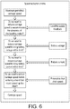
- Figure 6:
- shows, diagrammatically, how the various elements shown in
Figure 5 may be combined to generate a maximum carriage speed. - Referring firstly to
Figures 1 and 2 , the invention provides a method for controlling the speed of astairlift 10; and a stairlift including a speed control facility. As is typical, thestairlift 10 includes arail 11 that extends between adjacent levels in a building (not shown), and acarriage 12 mounted on the rail for movement along the rail. Thecarriage 12 includes acarriage drive motor 13 to displace the carriage up and down therail 11, apinion 14 mounted on the output of the motor meshing with adrive rack 15 extending along the underside of therail 11. Those skilled in the art will appreciate that other drive arrangements could be used, the precise drive arrangement not forming part of this invention. - Mounted on, and extending above, the
carriage 12 is achair 16. As is well known in the art, the chair is mounted in such a manner that, when thecarriage 12 moves through a transition bend in the rail, the chair remains horizontal. In some stairlifts, the chair and carriage are rotated as a unit with respect to the rail but, in the embodiment described herein, the chair is fixed to the upper end ofarm 17, the lower end ofarm 17 being pivotally mounted to the carriage alongaxis 18. Alevelling gear 19 is fixed to the arm aboutaxis 18, thegear 19 meshing withpinion 20 mounted on the output of alevelling motor 21. Thus, as thecarriage 12 moves through transition bends in the rail 11 (later described with reference toFigure 3 below), the relative orientation between the carriage and the chair is altered by operation of themotor 21 to maintain the chair substantially level. - In the form shown the
chair 16 comprises aseat surface 25, abackrest 26, and spacedarmrests 27. A user-operatedcontrol 28 is mounted on one of the armrests to allow a user seated in the chair to control the movement of the carriage along the rail. Although not shown for reasons of clarity, the chair will also typically include a footrest to support the user's feet during operation of the stairlift. - Control of the
carriage drive motor 13 and thelevelling motor 21 is effected by an electronic control unit (ECU) 30 mounted within the carriage. The ECU 30 receives inputs from thehand control 28 as well as from various sensors mounted on thecarriage 12 and/or thechair 16 to ensure appropriate operation of thelevelling motor 21 to maintain theseat 25 level at all times. These sensors preferably include agyroscope 31 mounted in the carriage and arranged to provide an output representative of the speed of rotation of the carriage in transition bends (roll). Thegyroscope 31 may also have the functionality to measure the speed of rotation as the carriage moves through horizontal bends (yaw), this being so if the gyroscope is a 3-axis gyroscope. However the speed of rotation in yaw could also be measured using a gyroscope mounted on the chair. The sensors further include acarriage accelerometer 32, acarriage encoder 33 operable to monitor the rotation of thedrive pinion 14, and achair encoder 34 operable to monitor the rotation of thechair leveling gear 19. - Those skilled in the art will recognize that means of measuring rates of angular rotation other than gyroscopes could be used in reducing the invention to practice without departing from the scope of the invention.
- The present invention describes a method and/or system to improve the overall speed at which a stairlift carriage moves between the ends of the stairlift rail. This will invariably, though not necessarily, require monitoring of the maximum overall speed of the stairlift chair to ensure that the permitted maximum speed is not exceeded. One method of monitoring the speed of a reference point on the chair is therefore described.
- As stated above, the maximum allowable speed of a stairlift is regulated. European Standard EN 81-40:2008 (E) establishes the position of a speed reference point indicated by 35 in the drawings. This point is located on the longitudinal centerline of the
seat 25, 250 mm forward of a vertical line down through the forward face of thebackrest 26. The standard prescribes that the speed of thereference point 35 shall not exceed 0.15 m/s in any direction. In other jurisdictions the speed limit may be some other figure. - Turning now to
Figures 3 & 4 , it will be appreciated that, as the stairlift carriage moves along the rail, the speed of thespeed reference point 35 may vary relative to the speed of the carriage. InFigure 3 a section ofrail 11 is shown in elevation, the section including a positive transition bend at (A) and a negative transition bend at (C). It follows that, for the purposes of this disclosure, a positive transition bend is a bend in a vertical plane in which the angle of inclination of the rail increases when moving in an upward direction. A negative transition bend is a bend in a vertical plane in which the angle of inclination of the rail reduces when moving in an upward direction. Assuming a constant carriage speed, when the stairlift is moving along a straight section of rail, e.g. position (B) inFigure 3 , thereference point 35 will be moving at the same speed as the carriage i.e. V1 = VC1. When the carriage is moving through a positive transition bend thereference point 35 moves through a shorter arc than the carriage and thus V2 < VC2. When the carriage moves through a negative transition bend, thereference point 35 moves through a longer arc than the carriage and is thus speeded-up relative to the carriage. V3 > VC3. It is thus apparent that the critical determining point or points for speed control are when the carriage is moving through a negative transition bend. -
Figure 4 illustrates alternative sections ofrail 11 in a substantially horizontal plane.Rail section 11a is mounted on the inside of astaircase 36 and includes an inside bend at position (E) while rail section 11b is mounted on the outside of the staircase and includes an outside bend at position (F). It will be appreciated that, in reality, a stairlift installation will normally include either all inside or all outside bends and, providing there are no physical limitations to dictate otherwise, it is preferred to mount the rail on the inside edge of thestaircase 36. - When the carriage is moving along a straight section of rail, as shown at position (D) in
Figure 4 , V4 = VC4. When the carriage is moving through the inside bend (E) as shown, thereference point 35 moves through a longer arc than the carriage and is thus speeded up relative to the carriage. V5 > VC5. - When the carriage is moving through the outside bend (F) as shown, the
reference point 35 moves through a shorter arc than the carriage and V6 < VC6. Returning toFigures 1 & 2 , physically the chair seat is offset from the carriage by an effective radius Rpiv above the rail/carriage pivot point. The seat itself is a certain distance Rsh above the rail/drive pinion interface. Thereference point 35 on the chair surface is also cantilevered outwards from a vertical plane through the centerline of the rail by a distance Rscd. - When the chair is levelling upon the carriage traversing a transition curve in the rail (in reality, the chair maintaining level as the carriage displaces), the chair surface is assumed to be moving in a partial circle of radius Rsh while the leveling arm supporting the chair surface is also rotating about a radius of Rpiv.
- A basic form of speed control according to the invention may be effected as follows:
Output signals from the 3-axis gyroscope are monitored by theECU 30. Should the signals in either roll or yaw (generated by the carriage moving through a transition bend or horizontal bend respectively) exceed pre-determined thresholds, the ECU triggers thecarriage drive motor 13 to slow down to a prescribed lower speed. The thresholds applied to the gyroscope outputs, and the carriage drive motor speeds, are set to ensure that the speed of thereference point 35 on the chair does not exceed the prescribed limit in both transition bends or horizontal bends. - The speed control method described above contemplates the carriage moving at two defined speeds only, a higher speed when traversing straight sections of rail and a lower speed when traversing bends. However the use of gyroscopes or similar electronic devices provides an opportunity to incorporate a more sophisticated reactive speed control system wherein the speed of the
reference point 35 is continually calculated and the speed of thecarriage drive motor 13 controlled to maintain a higher overall speed. To this end the speed of the reference point in rail bends is first established. - Simplified equations to describe the relative motion aligned to the stairlift rail for transition or roll curves is:

- Where Ǿ gyro roll Sec - 1 is the carriage gyro output. Ǿ gravity is the carriage accelerometer angle versus gravity.
- There is an extra term to describe the additional speed caused by inside/outside or yaw curves:

- So the complete equation is:

- This set of equations is simple enough for an on-board microcontroller to calculate in real time, based on the accelerometer and gyroscopic data from the chair and carriage. This means that at any point the chair seat speed can be calculated and the speed of the
carriage motor 13 controlled, reactively, to maintain the speed of thereference point 35 at the desired level. Ignoring other limitations, this speed level may be the maximum permitted by the regulations. - It will be appreciated that the system for calculating true chair speed is entirely reactive and, accordingly, the carriage takes time to change speed when entering and exiting bends. To improve system efficiency and/or passenger comfort it is advantageous to include some form of pre-emptive speed adjustment around those positions on the rail where significant changes of speed occur. A further advantage of pre-emptively adjusting the speed is that excessive changes of speed, which could and invariably would arise in a purely reactive system attempting to maximize speed, can be removed.
- These adjustments are made depending on the position of the carriage on the rail and may vary according to the nature and angle of the bend being negotiated. The pre-emptive adjustment facility is preferably 'self-learning', and compiles a set of speed settings (or change in speed settings) at particular positions along the rail which will ensure comfortable changes in speed while maintaining optimum overall speed.
- In addition to the maximum speed setting described above, other factors influence speed setting and thus influence the overall time taken for the carriage to move up and down the rail.
- Turning now to
Figure 5 , the diagram shows various factors that are taken into account in the preferred implementation of the invention. - In this implementation the Statutory Top Speed is the maximum permissible speed at which the reference point on the chair may travel. As a first step the True Chair Speed is monitored in real time, in the manner described above, compared with the Statutory Top Speed and, if necessary adjustment made to the Carriage Speed to maintain True Chair Speed below the permissible maximum.
- As indicated in
Figure 5 , Battery Voltage is monitored and the Carriage Speed adjusted, if necessary, to maintain the battery voltage at or just above the permitted level. Battery Voltage will also vary as the carriage moves through a transition bend in the rail and the levelling motor operates to maintain the chair level. In this event the overall battery demand will inevitably reduce the battery capacity available to the main carriage motor. Motor Current is also monitored as an influence on carriage speed. Motor current will vary according to passenger weight and according to whether the carriage is moving up the rail or down the rail. Thus theECU 30 can monitor the Motor Current in real time against a maximum permissible current draw and adjust Carriage Speed to maintain the Motor Current close to the limit and the speed as close as possible to the maximum permitted speed. - As described above, merely establishing maximum speeds by looking at True Chair Speed, has the potential to subject a passenger to uncomfortable speed changes as the carriage enters and exits bends. Accordingly Pre-emptive braking and acceleration may be applied. This function limits carriage speed against changes in chair speed due to the chair rotating about the carriage. It does this by monitoring the True Chair Speed during a journey, looking for rapid speed changes, commonly referred to as speed deltas. These speed deltas are stored in a memory bank against the positions on the rail at which they occurred. On the next run the ECU scans the memory bank for upcoming speed deltas and pre-emptively applies them as a speed limit, due to the fact that it takes time to change speed as acceleration/deceleration is limited. This allows the carriage to smoothly slow as it enters a bend and so maintain comfort for the user.
- A further factor to be added into the determination of Carriage Speed is levelling under-speed. This takes into account the fact that as the carriage moves through a transition bend in the rail, the levelling
motor 21 operates to maintain the chair level. If the carriage motor speed is not matched appropriately to the levelling motor speed, the chair could go 'off level' to an impermissible extent. - Turning now to
Figure 6 , the various factors depicted inFigure 5 are processed in theECU 30 to provide a speed signal output to thecarriage drive motor 13. - As a starting point a Maximum Permitted Carriage Speed is prescribed which may be the maximum speed permitted prescribed by regulation or may be another maximum speed programmed into the ECU. The first factor shown in
Figure 6 influencing this maximum speed is a feedback signal from the levelling motor, which signal may lead to a reduction in the speed of the carriage motor to ensure that the chair does not go off-level because of the relative slowness of the levelling motor as the carriage moves through a transition bend in the rail. - In the next step the ECU looks at Battery Voltage and, if necessary, adjusts the Maximum Permitted Carriage Speed to bring the battery voltage within permissible limits. Similarly the ECU looks at Battery Current and, if necessary, reduces Maximum Permitted Carriage Speed to bring the battery current within limit.
- Finally the ECU looks at speed deltas as the carriage moves along the rail, in the manner described above, and adjusts the Maximum Permitted Carriage Speed to maintain speed deltas at levels which ensure passenger comfort.
- The resultant output Carriage Speed can be applied to a conventional PID loop (not shown) to rotate the
motor 13 at the speed demanded. In this case feedback control is provided byencoder 33. - It will thus be appreciated that the present invention provides a novel method and system for controlling stairlift speed in which the speed at any point along the rail is not set arbitrarily or to fixed limits but, rather, is determined in real time in response to a number of continually varying parameters. The system can continually adapt to these varying parameters to output varying speeds and thus allow a reduced overall journey time to be realized.
Claims (11)
- A method of controlling the speed of a stairlift (10), the stairlift having:- a rail (11) having at least one bend (A, C, E, F) therein;- a carriage (12) mounted on said rail;- a electric carriage drive motor (13) operable to move said carriage (12) along said rail (11);- at least one battery to power said carriage drive motor (13); and- a chair (16) mounted on said carriage (12),said method includingi) generating a first signal representative of current drawn by said carriage drive motor (13);ii) generating a second signal representative of a voltage level in said at least one battery or the power draw from said battery;
said method being characterized by:iii) generating one or more third signals representative of the speed of a reference point (35) on said chair and:
using said first, second and third signals as controls over the speed of said carriage drive motor (13). - A method as claimed in claim 1 wherein said carriage (12) is rotatable with respect to said chair (16), said method including generating a signal representative of the relative angular velocity between said carriage and said chair as said carriage moves through a transition bend (A, C) in said rail.
- A method as claimed in claim 2 further including comparing said relative angular velocity with the speed of said carriage drive motor (13) and, if necessary, adjusting the speed of said carriage drive motor to ensure that said chair (16) is maintained substantially level.
- A method as claimed in any one of the preceding claims including generating a signal representative of the angular velocity of said carriage as said carriage (12) moves through a horizontal bend (E, F) in said rail.
- A method as claimed in any one of claims 1 to 4 wherein measurement of the rotational velocities of said carriage are effected using one more gyroscopes (31) mounted in or on said carriage and/or said chair.
- A method as claimed in claim 5 wherein signals from said one or more gyroscopes (31) are processed to establish the speed of said reference point (35) on said chair.
- A method as claimed in any one of the preceding claims further comprising adjusting the speed of said carriage pre-emptively having regard to the position of said carriage on said rail.
- A method as claimed in claim 7 comprising learning and storing in a memory, acceptable speed changes at various positions on said rail (11).
- A stairlift, (10) including:- a rail (11) having at least one bend (A, C, E, F) therein;- a carriage (12) mounted on said rail;- an electric carriage drive motor (13) operable to move said carriage (12) along said rail (11);- at least one battery to power said carriage drive motor (13); and- a chair (16) mounted on said carriage (12);said stairlift further including a speed control facility configured toi) generate a first signal representative of current drawn by said electric carriage drive motor,ii) generate a second signal representative of a voltage level in said at least one battery or the power draw from said battery;
characterized in that said speed control facility is further configured toiii) generate one or more third signals representative of the speed of a reference point (35) on said chair (16); andto apply said first, second and third signals as controls over the speed of said carriage drive motor (13). - A stairlift as claimed in claim 9 wherein said speed control facility includes one or more gyroscopes (31) mounted on or in said carriage (12) and/or said chair (16) to generate said one or more first signals.
- A stairlift as claimed in claim 9 or claim 10 wherein said speed control facility includes a 3-axis gyroscope (31) mounted in said carriage (12).
Applications Claiming Priority (2)
| Application Number | Priority Date | Filing Date | Title |
|---|---|---|---|
| GB1505467.9A GB2536909A (en) | 2015-03-30 | 2015-03-30 | Improvements in or relating to stairlifts |
| PCT/GB2016/050867 WO2016156822A1 (en) | 2015-03-30 | 2016-03-29 | Improvements in or relating to stairlifts |
Publications (2)
| Publication Number | Publication Date |
|---|---|
| EP3277613A1 EP3277613A1 (en) | 2018-02-07 |
| EP3277613B1 true EP3277613B1 (en) | 2019-03-27 |
Family
ID=53178379
Family Applications (1)
| Application Number | Title | Priority Date | Filing Date |
|---|---|---|---|
| EP16715041.6A Active EP3277613B1 (en) | 2015-03-30 | 2016-03-29 | Controlling the speed of a stairlift |
Country Status (5)
| Country | Link |
|---|---|
| US (1) | US10752467B2 (en) |
| EP (1) | EP3277613B1 (en) |
| CN (1) | CN107428508B (en) |
| GB (1) | GB2536909A (en) |
| WO (1) | WO2016156822A1 (en) |
Families Citing this family (10)
| Publication number | Priority date | Publication date | Assignee | Title |
|---|---|---|---|---|
| GB2535542A (en) * | 2015-02-23 | 2016-08-24 | Stannah Stairlifts Ltd | Improvements in or relating to stairlifts |
| GB2542822B (en) * | 2015-09-30 | 2021-03-24 | Acorn Mobility Services Ltd | Lift system and method |
| DE102017202010A1 (en) * | 2017-02-08 | 2018-08-09 | Thyssenkrupp Ag | stair lift |
| DE102017203774A1 (en) * | 2017-03-08 | 2018-09-13 | Thyssenkrupp Ag | Method of controlling a stairlift and stairlift |
| GB2565076B (en) * | 2017-07-31 | 2022-03-02 | Stannah Stairlifts Ltd | Improvements in or relating to stairlifts |
| GB201712745D0 (en) * | 2017-08-09 | 2017-09-20 | Stannah Stairlifts Ltd | Improvements in or relating to stairlifts |
| GB2572805B (en) * | 2018-04-12 | 2022-07-13 | Stannah Stairlifts Ltd | Improvements in or relating to stairlifts |
| US11691850B2 (en) * | 2018-08-21 | 2023-07-04 | Tk Home Solutions B.V. | Method of configuring a platform lift |
| CN116409694B (en) * | 2021-12-31 | 2025-11-04 | 湖南大举信息科技有限公司 | Car posture adjustment device and adjustment method for intelligent parallel elevator systems |
| ES3059704T3 (en) * | 2023-01-30 | 2026-03-23 | Tk Home Solutions B V | Method to operate a stairlift with two speed profiles |
Family Cites Families (14)
| Publication number | Priority date | Publication date | Assignee | Title |
|---|---|---|---|---|
| GB9400056D0 (en) | 1994-01-05 | 1994-03-02 | Stannah Stairlifts Ltd | Stairlift levelling arrangement |
| AU2001257322A1 (en) * | 2000-05-05 | 2001-11-20 | Advanced Materials Corporation | Motor controller system for battery-powered motors |
| ITMI20051904A1 (en) * | 2005-10-10 | 2007-04-11 | Vimec S P A | SERVOSCALA WITH MEANS OF ANGULAR ADJUSTMENT |
| US20130231814A1 (en) * | 2006-03-06 | 2013-09-05 | Sterraclimb Llc | Stair-climbing surveillance vehicle |
| US20080128213A1 (en) * | 2006-11-30 | 2008-06-05 | Harris Timothy R | Combination electrical and battery-powered control system for stairway chairlift |
| NL2002503C2 (en) | 2009-02-06 | 2010-08-09 | Ooms Otto Bv | Apparatus for transporting a load from a first to a second level, in particular a stairlift. |
| CN201647771U (en) | 2009-04-20 | 2010-11-24 | 张克林 | Curve-type lifting device with remote help function interface |
| CN102259780B (en) * | 2011-03-17 | 2013-11-27 | 太仓市康辉科技发展有限公司 | Control system of stair curve guide way climbing robot |
| CN202130964U (en) * | 2011-05-19 | 2012-02-01 | 哈尔滨工程大学 | Suspension traction-type seat elevator |
| GB2495953B (en) * | 2011-10-26 | 2015-11-18 | Acorn Mobility Services Ltd | Lift system |
| US9004201B2 (en) * | 2012-04-18 | 2015-04-14 | Board Of Trustees Of Michigan State University | Jumping robot |
| JP2013245107A (en) * | 2012-05-29 | 2013-12-09 | Kuma Lift Gijutsu Kenkyusho:Kk | Chair type stair lift |
| GB2542488B (en) * | 2012-12-14 | 2019-11-13 | Stannah Stairlifts Ltd | Improvements in or relating to stairlifts |
| NL2010013C2 (en) * | 2012-12-19 | 2014-06-23 | Thyssenkrupp Accessibility B V | Stair lift drive. |
-
2015
- 2015-03-30 GB GB1505467.9A patent/GB2536909A/en not_active Withdrawn
-
2016
- 2016-03-29 WO PCT/GB2016/050867 patent/WO2016156822A1/en not_active Ceased
- 2016-03-29 CN CN201680017087.0A patent/CN107428508B/en not_active Expired - Fee Related
- 2016-03-29 EP EP16715041.6A patent/EP3277613B1/en active Active
- 2016-03-29 US US15/563,272 patent/US10752467B2/en not_active Expired - Fee Related
Non-Patent Citations (1)
| Title |
|---|
| None * |
Also Published As
| Publication number | Publication date |
|---|---|
| US10752467B2 (en) | 2020-08-25 |
| CN107428508B (en) | 2019-10-22 |
| WO2016156822A1 (en) | 2016-10-06 |
| CN107428508A (en) | 2017-12-01 |
| EP3277613A1 (en) | 2018-02-07 |
| GB2536909A (en) | 2016-10-05 |
| US20180072537A1 (en) | 2018-03-15 |
| GB201505467D0 (en) | 2015-05-13 |
Similar Documents
| Publication | Publication Date | Title |
|---|---|---|
| US10752467B2 (en) | In or relating to stairlifts | |
| EP3261972B1 (en) | Stairlift speed control | |
| US9610862B2 (en) | Seat position sensing and adjustment | |
| EP2987041B1 (en) | Moving body control device and moving body control method | |
| CA3090583C (en) | Stairlift system | |
| JPH09207653A (en) | Irradiation direction control device for vehicle lighting fixture | |
| JPWO2013014696A1 (en) | Inverted moving body control device, control method thereof, and program | |
| JP4322960B2 (en) | Elevator deceleration method and apparatus | |
| EP2338775A1 (en) | Self-propelled vehicle, and device and method for controlling same | |
| JP2001511757A (en) | Stair climber | |
| JP6485789B1 (en) | Automatic operation device of model train and automatic adjustment method of acceleration / deceleration | |
| EP3819244B1 (en) | Elevator system including a passenger ear comfort application | |
| JP5772373B2 (en) | Inverted moving body control device and control method thereof | |
| GB2527410A (en) | Lift system | |
| JP4594757B2 (en) | Electric vehicle travel control device | |
| KR20150146177A (en) | Electric power steering system and vehicle pulling compensation method using them | |
| CN117325601A (en) | Vehicle chassis balance control method, electronic device and storage medium | |
| JP2019139005A (en) | Balance training device | |
| JP2016049951A (en) | Inverted two-wheel type moving body and control method therefor | |
| JPH11256923A (en) | Method and device for controlling traveling of electric partition |
Legal Events
| Date | Code | Title | Description |
|---|---|---|---|
| STAA | Information on the status of an ep patent application or granted ep patent |
Free format text: STATUS: THE INTERNATIONAL PUBLICATION HAS BEEN MADE |
|
| PUAI | Public reference made under article 153(3) epc to a published international application that has entered the european phase |
Free format text: ORIGINAL CODE: 0009012 |
|
| STAA | Information on the status of an ep patent application or granted ep patent |
Free format text: STATUS: REQUEST FOR EXAMINATION WAS MADE |
|
| 17P | Request for examination filed |
Effective date: 20170830 |
|
| AK | Designated contracting states |
Kind code of ref document: A1 Designated state(s): AL AT BE BG CH CY CZ DE DK EE ES FI FR GB GR HR HU IE IS IT LI LT LU LV MC MK MT NL NO PL PT RO RS SE SI SK SM TR |
|
| AX | Request for extension of the european patent |
Extension state: BA ME |
|
| DAV | Request for validation of the european patent (deleted) | ||
| DAX | Request for extension of the european patent (deleted) | ||
| GRAP | Despatch of communication of intention to grant a patent |
Free format text: ORIGINAL CODE: EPIDOSNIGR1 |
|
| STAA | Information on the status of an ep patent application or granted ep patent |
Free format text: STATUS: GRANT OF PATENT IS INTENDED |
|
| INTG | Intention to grant announced |
Effective date: 20181025 |
|
| GRAS | Grant fee paid |
Free format text: ORIGINAL CODE: EPIDOSNIGR3 |
|
| GRAA | (expected) grant |
Free format text: ORIGINAL CODE: 0009210 |
|
| STAA | Information on the status of an ep patent application or granted ep patent |
Free format text: STATUS: THE PATENT HAS BEEN GRANTED |
|
| AK | Designated contracting states |
Kind code of ref document: B1 Designated state(s): AL AT BE BG CH CY CZ DE DK EE ES FI FR GB GR HR HU IE IS IT LI LT LU LV MC MK MT NL NO PL PT RO RS SE SI SK SM TR |
|
| REG | Reference to a national code |
Ref country code: GB Ref legal event code: FG4D |
|
| REG | Reference to a national code |
Ref country code: CH Ref legal event code: EP |
|
| REG | Reference to a national code |
Ref country code: AT Ref legal event code: REF Ref document number: 1112805 Country of ref document: AT Kind code of ref document: T Effective date: 20190415 |
|
| REG | Reference to a national code |
Ref country code: IE Ref legal event code: FG4D |
|
| REG | Reference to a national code |
Ref country code: DE Ref legal event code: R096 Ref document number: 602016011588 Country of ref document: DE |
|
| REG | Reference to a national code |
Ref country code: NL Ref legal event code: FP |
|
| PG25 | Lapsed in a contracting state [announced via postgrant information from national office to epo] |
Ref country code: LT Free format text: LAPSE BECAUSE OF FAILURE TO SUBMIT A TRANSLATION OF THE DESCRIPTION OR TO PAY THE FEE WITHIN THE PRESCRIBED TIME-LIMIT Effective date: 20190327 Ref country code: FI Free format text: LAPSE BECAUSE OF FAILURE TO SUBMIT A TRANSLATION OF THE DESCRIPTION OR TO PAY THE FEE WITHIN THE PRESCRIBED TIME-LIMIT Effective date: 20190327 Ref country code: SE Free format text: LAPSE BECAUSE OF FAILURE TO SUBMIT A TRANSLATION OF THE DESCRIPTION OR TO PAY THE FEE WITHIN THE PRESCRIBED TIME-LIMIT Effective date: 20190327 Ref country code: NO Free format text: LAPSE BECAUSE OF FAILURE TO SUBMIT A TRANSLATION OF THE DESCRIPTION OR TO PAY THE FEE WITHIN THE PRESCRIBED TIME-LIMIT Effective date: 20190627 |
|
| PG25 | Lapsed in a contracting state [announced via postgrant information from national office to epo] |
Ref country code: BG Free format text: LAPSE BECAUSE OF FAILURE TO SUBMIT A TRANSLATION OF THE DESCRIPTION OR TO PAY THE FEE WITHIN THE PRESCRIBED TIME-LIMIT Effective date: 20190627 Ref country code: GR Free format text: LAPSE BECAUSE OF FAILURE TO SUBMIT A TRANSLATION OF THE DESCRIPTION OR TO PAY THE FEE WITHIN THE PRESCRIBED TIME-LIMIT Effective date: 20190628 Ref country code: LV Free format text: LAPSE BECAUSE OF FAILURE TO SUBMIT A TRANSLATION OF THE DESCRIPTION OR TO PAY THE FEE WITHIN THE PRESCRIBED TIME-LIMIT Effective date: 20190327 Ref country code: RS Free format text: LAPSE BECAUSE OF FAILURE TO SUBMIT A TRANSLATION OF THE DESCRIPTION OR TO PAY THE FEE WITHIN THE PRESCRIBED TIME-LIMIT Effective date: 20190327 Ref country code: HR Free format text: LAPSE BECAUSE OF FAILURE TO SUBMIT A TRANSLATION OF THE DESCRIPTION OR TO PAY THE FEE WITHIN THE PRESCRIBED TIME-LIMIT Effective date: 20190327 |
|
| REG | Reference to a national code |
Ref country code: AT Ref legal event code: MK05 Ref document number: 1112805 Country of ref document: AT Kind code of ref document: T Effective date: 20190327 |
|
| PG25 | Lapsed in a contracting state [announced via postgrant information from national office to epo] |
Ref country code: CZ Free format text: LAPSE BECAUSE OF FAILURE TO SUBMIT A TRANSLATION OF THE DESCRIPTION OR TO PAY THE FEE WITHIN THE PRESCRIBED TIME-LIMIT Effective date: 20190327 Ref country code: RO Free format text: LAPSE BECAUSE OF FAILURE TO SUBMIT A TRANSLATION OF THE DESCRIPTION OR TO PAY THE FEE WITHIN THE PRESCRIBED TIME-LIMIT Effective date: 20190327 Ref country code: SK Free format text: LAPSE BECAUSE OF FAILURE TO SUBMIT A TRANSLATION OF THE DESCRIPTION OR TO PAY THE FEE WITHIN THE PRESCRIBED TIME-LIMIT Effective date: 20190327 Ref country code: ES Free format text: LAPSE BECAUSE OF FAILURE TO SUBMIT A TRANSLATION OF THE DESCRIPTION OR TO PAY THE FEE WITHIN THE PRESCRIBED TIME-LIMIT Effective date: 20190327 Ref country code: EE Free format text: LAPSE BECAUSE OF FAILURE TO SUBMIT A TRANSLATION OF THE DESCRIPTION OR TO PAY THE FEE WITHIN THE PRESCRIBED TIME-LIMIT Effective date: 20190327 Ref country code: PT Free format text: LAPSE BECAUSE OF FAILURE TO SUBMIT A TRANSLATION OF THE DESCRIPTION OR TO PAY THE FEE WITHIN THE PRESCRIBED TIME-LIMIT Effective date: 20190727 Ref country code: AL Free format text: LAPSE BECAUSE OF FAILURE TO SUBMIT A TRANSLATION OF THE DESCRIPTION OR TO PAY THE FEE WITHIN THE PRESCRIBED TIME-LIMIT Effective date: 20190327 |
|
| REG | Reference to a national code |
Ref country code: CH Ref legal event code: PL |
|
| PG25 | Lapsed in a contracting state [announced via postgrant information from national office to epo] |
Ref country code: PL Free format text: LAPSE BECAUSE OF FAILURE TO SUBMIT A TRANSLATION OF THE DESCRIPTION OR TO PAY THE FEE WITHIN THE PRESCRIBED TIME-LIMIT Effective date: 20190327 Ref country code: LU Free format text: LAPSE BECAUSE OF NON-PAYMENT OF DUE FEES Effective date: 20190329 Ref country code: SM Free format text: LAPSE BECAUSE OF FAILURE TO SUBMIT A TRANSLATION OF THE DESCRIPTION OR TO PAY THE FEE WITHIN THE PRESCRIBED TIME-LIMIT Effective date: 20190327 |
|
| REG | Reference to a national code |
Ref country code: BE Ref legal event code: MM Effective date: 20190331 |
|
| PG25 | Lapsed in a contracting state [announced via postgrant information from national office to epo] |
Ref country code: IS Free format text: LAPSE BECAUSE OF FAILURE TO SUBMIT A TRANSLATION OF THE DESCRIPTION OR TO PAY THE FEE WITHIN THE PRESCRIBED TIME-LIMIT Effective date: 20190727 Ref country code: AT Free format text: LAPSE BECAUSE OF FAILURE TO SUBMIT A TRANSLATION OF THE DESCRIPTION OR TO PAY THE FEE WITHIN THE PRESCRIBED TIME-LIMIT Effective date: 20190327 |
|
| REG | Reference to a national code |
Ref country code: DE Ref legal event code: R097 Ref document number: 602016011588 Country of ref document: DE |
|
| PG25 | Lapsed in a contracting state [announced via postgrant information from national office to epo] |
Ref country code: LI Free format text: LAPSE BECAUSE OF NON-PAYMENT OF DUE FEES Effective date: 20190331 Ref country code: MC Free format text: LAPSE BECAUSE OF FAILURE TO SUBMIT A TRANSLATION OF THE DESCRIPTION OR TO PAY THE FEE WITHIN THE PRESCRIBED TIME-LIMIT Effective date: 20190327 Ref country code: CH Free format text: LAPSE BECAUSE OF NON-PAYMENT OF DUE FEES Effective date: 20190331 Ref country code: DK Free format text: LAPSE BECAUSE OF FAILURE TO SUBMIT A TRANSLATION OF THE DESCRIPTION OR TO PAY THE FEE WITHIN THE PRESCRIBED TIME-LIMIT Effective date: 20190327 Ref country code: IE Free format text: LAPSE BECAUSE OF NON-PAYMENT OF DUE FEES Effective date: 20190329 |
|
| PLBE | No opposition filed within time limit |
Free format text: ORIGINAL CODE: 0009261 |
|
| STAA | Information on the status of an ep patent application or granted ep patent |
Free format text: STATUS: NO OPPOSITION FILED WITHIN TIME LIMIT |
|
| PG25 | Lapsed in a contracting state [announced via postgrant information from national office to epo] |
Ref country code: SI Free format text: LAPSE BECAUSE OF FAILURE TO SUBMIT A TRANSLATION OF THE DESCRIPTION OR TO PAY THE FEE WITHIN THE PRESCRIBED TIME-LIMIT Effective date: 20190327 Ref country code: BE Free format text: LAPSE BECAUSE OF NON-PAYMENT OF DUE FEES Effective date: 20190331 |
|
| 26N | No opposition filed |
Effective date: 20200103 |
|
| PG25 | Lapsed in a contracting state [announced via postgrant information from national office to epo] |
Ref country code: TR Free format text: LAPSE BECAUSE OF FAILURE TO SUBMIT A TRANSLATION OF THE DESCRIPTION OR TO PAY THE FEE WITHIN THE PRESCRIBED TIME-LIMIT Effective date: 20190327 |
|
| PG25 | Lapsed in a contracting state [announced via postgrant information from national office to epo] |
Ref country code: MT Free format text: LAPSE BECAUSE OF NON-PAYMENT OF DUE FEES Effective date: 20190329 |
|
| PG25 | Lapsed in a contracting state [announced via postgrant information from national office to epo] |
Ref country code: CY Free format text: LAPSE BECAUSE OF FAILURE TO SUBMIT A TRANSLATION OF THE DESCRIPTION OR TO PAY THE FEE WITHIN THE PRESCRIBED TIME-LIMIT Effective date: 20190327 |
|
| PG25 | Lapsed in a contracting state [announced via postgrant information from national office to epo] |
Ref country code: HU Free format text: LAPSE BECAUSE OF FAILURE TO SUBMIT A TRANSLATION OF THE DESCRIPTION OR TO PAY THE FEE WITHIN THE PRESCRIBED TIME-LIMIT; INVALID AB INITIO Effective date: 20160329 |
|
| PG25 | Lapsed in a contracting state [announced via postgrant information from national office to epo] |
Ref country code: MK Free format text: LAPSE BECAUSE OF FAILURE TO SUBMIT A TRANSLATION OF THE DESCRIPTION OR TO PAY THE FEE WITHIN THE PRESCRIBED TIME-LIMIT Effective date: 20190327 |
|
| P01 | Opt-out of the competence of the unified patent court (upc) registered |
Effective date: 20230523 |
|
| PGFP | Annual fee paid to national office [announced via postgrant information from national office to epo] |
Ref country code: NL Payment date: 20250530 Year of fee payment: 10 |
|
| PGFP | Annual fee paid to national office [announced via postgrant information from national office to epo] |
Ref country code: DE Payment date: 20250529 Year of fee payment: 10 |
|
| PGFP | Annual fee paid to national office [announced via postgrant information from national office to epo] |
Ref country code: GB Payment date: 20250530 Year of fee payment: 10 |
|
| PGFP | Annual fee paid to national office [announced via postgrant information from national office to epo] |
Ref country code: IT Payment date: 20250529 Year of fee payment: 10 |
|
| PGFP | Annual fee paid to national office [announced via postgrant information from national office to epo] |
Ref country code: FR Payment date: 20250529 Year of fee payment: 10 |