EP3277162B1 - Signalqualitätsbestimmung für am körper tragbare pulsmessvorrichtung - Google Patents
Signalqualitätsbestimmung für am körper tragbare pulsmessvorrichtung Download PDFInfo
- Publication number
- EP3277162B1 EP3277162B1 EP16717027.3A EP16717027A EP3277162B1 EP 3277162 B1 EP3277162 B1 EP 3277162B1 EP 16717027 A EP16717027 A EP 16717027A EP 3277162 B1 EP3277162 B1 EP 3277162B1
- Authority
- EP
- European Patent Office
- Prior art keywords
- data window
- sensing device
- pulse
- computer
- samples
- Prior art date
- Legal status (The legal status is an assumption and is not a legal conclusion. Google has not performed a legal analysis and makes no representation as to the accuracy of the status listed.)
- Not-in-force
Links
Images






Classifications
-
- A—HUMAN NECESSITIES
- A61—MEDICAL OR VETERINARY SCIENCE; HYGIENE
- A61B—DIAGNOSIS; SURGERY; IDENTIFICATION
- A61B5/00—Measuring for diagnostic purposes; Identification of persons
- A61B5/72—Signal processing specially adapted for physiological signals or for diagnostic purposes
- A61B5/7203—Signal processing specially adapted for physiological signals or for diagnostic purposes for noise prevention, reduction or removal
- A61B5/7207—Signal processing specially adapted for physiological signals or for diagnostic purposes for noise prevention, reduction or removal of noise induced by motion artifacts
-
- A—HUMAN NECESSITIES
- A61—MEDICAL OR VETERINARY SCIENCE; HYGIENE
- A61B—DIAGNOSIS; SURGERY; IDENTIFICATION
- A61B5/00—Measuring for diagnostic purposes; Identification of persons
- A61B5/02—Detecting, measuring or recording for evaluating the cardiovascular system, e.g. pulse, heart rate, blood pressure or blood flow
- A61B5/024—Measuring pulse rate or heart rate
- A61B5/02438—Measuring pulse rate or heart rate with portable devices, e.g. worn by the patient
-
- A—HUMAN NECESSITIES
- A61—MEDICAL OR VETERINARY SCIENCE; HYGIENE
- A61B—DIAGNOSIS; SURGERY; IDENTIFICATION
- A61B5/00—Measuring for diagnostic purposes; Identification of persons
- A61B5/02—Detecting, measuring or recording for evaluating the cardiovascular system, e.g. pulse, heart rate, blood pressure or blood flow
- A61B5/024—Measuring pulse rate or heart rate
-
- A—HUMAN NECESSITIES
- A61—MEDICAL OR VETERINARY SCIENCE; HYGIENE
- A61B—DIAGNOSIS; SURGERY; IDENTIFICATION
- A61B5/00—Measuring for diagnostic purposes; Identification of persons
- A61B5/02—Detecting, measuring or recording for evaluating the cardiovascular system, e.g. pulse, heart rate, blood pressure or blood flow
- A61B5/024—Measuring pulse rate or heart rate
- A61B5/02416—Measuring pulse rate or heart rate using photoplethysmograph signals, e.g. generated by infrared radiation
-
- A—HUMAN NECESSITIES
- A61—MEDICAL OR VETERINARY SCIENCE; HYGIENE
- A61B—DIAGNOSIS; SURGERY; IDENTIFICATION
- A61B5/00—Measuring for diagnostic purposes; Identification of persons
- A61B5/48—Other medical applications
- A61B5/4887—Locating particular structures in or on the body
- A61B5/489—Blood vessels
-
- A—HUMAN NECESSITIES
- A61—MEDICAL OR VETERINARY SCIENCE; HYGIENE
- A61B—DIAGNOSIS; SURGERY; IDENTIFICATION
- A61B5/00—Measuring for diagnostic purposes; Identification of persons
- A61B5/72—Signal processing specially adapted for physiological signals or for diagnostic purposes
- A61B5/7221—Determining signal validity, reliability or quality
-
- A—HUMAN NECESSITIES
- A61—MEDICAL OR VETERINARY SCIENCE; HYGIENE
- A61B—DIAGNOSIS; SURGERY; IDENTIFICATION
- A61B5/00—Measuring for diagnostic purposes; Identification of persons
- A61B5/72—Signal processing specially adapted for physiological signals or for diagnostic purposes
- A61B5/7235—Details of waveform analysis
- A61B5/7264—Classification of physiological signals or data, e.g. using neural networks, statistical classifiers, expert systems or fuzzy systems
-
- A—HUMAN NECESSITIES
- A61—MEDICAL OR VETERINARY SCIENCE; HYGIENE
- A61B—DIAGNOSIS; SURGERY; IDENTIFICATION
- A61B5/00—Measuring for diagnostic purposes; Identification of persons
- A61B5/02—Detecting, measuring or recording for evaluating the cardiovascular system, e.g. pulse, heart rate, blood pressure or blood flow
- A61B5/021—Measuring pressure in heart or blood vessels
- A61B5/02108—Measuring pressure in heart or blood vessels from analysis of pulse wave characteristics
-
- A—HUMAN NECESSITIES
- A61—MEDICAL OR VETERINARY SCIENCE; HYGIENE
- A61B—DIAGNOSIS; SURGERY; IDENTIFICATION
- A61B5/00—Measuring for diagnostic purposes; Identification of persons
- A61B5/68—Arrangements of detecting, measuring or recording means, e.g. sensors, in relation to patient
- A61B5/6801—Arrangements of detecting, measuring or recording means, e.g. sensors, in relation to patient specially adapted to be attached to or worn on the body surface
- A61B5/6802—Sensor mounted on worn items
- A61B5/681—Wristwatch-type devices
-
- G—PHYSICS
- G16—INFORMATION AND COMMUNICATION TECHNOLOGY [ICT] SPECIALLY ADAPTED FOR SPECIFIC APPLICATION FIELDS
- G16H—HEALTHCARE INFORMATICS, i.e. INFORMATION AND COMMUNICATION TECHNOLOGY [ICT] SPECIALLY ADAPTED FOR THE HANDLING OR PROCESSING OF MEDICAL OR HEALTHCARE DATA
- G16H50/00—ICT specially adapted for medical diagnosis, medical simulation or medical data mining; ICT specially adapted for detecting, monitoring or modelling epidemics or pandemics
- G16H50/20—ICT specially adapted for medical diagnosis, medical simulation or medical data mining; ICT specially adapted for detecting, monitoring or modelling epidemics or pandemics for computer-aided diagnosis, e.g. based on medical expert systems
Definitions
- a pulse pressure wave sensor provides a non-invasive mechanism for capturing the morphology of the pulse pressure wave which can be used in measuring heart rate, heart rate variability, arterial pressure, pulse wave velocity, and augmentation index.
- a pulse pressure wave sensor may be incorporated into a wearable device.
- WO2006094107 by Mohamed Diab et al describes how confidence in a physiological parameter is measured from physiological data responsive to the intensity of multiple wavelengths of optical radiation after tissue attenuation.
- the physiological parameter is estimated based upon the physiological data.
- Reference data clusters are stored according to known values of the physiological parameter.
- At least one of the data clusters is selected according to the estimated physiological parameter.
- the confidence measure is determined from a comparison of the selected data clusters and the physiological data.
- CN103845038 by Junyan Wang et al discloses acquiring a physical sign signal of a human body by virtue of acquiring equipment, performing scene recognition by use of the acquired physical sign signal, performing signal quality evaluation on the acquired physical sign signal according to a recognized scene, and uploading the physical sign signal with qualified signal quality to a server.
- Signal quality evaluation is realized at the acquiring equipment, and signals with poor quality are not transmitted and stored, so that the transmission pressure and the storage pressure are reduced and the use stage and application scene of the equipment and the current human body state can be automatically analyzed.
- AdaBoost AdaBoost
- Boost Boost
- the cascade can be viewed as an object specific focus-of-attention mechanism which unlike previous approaches provides statistical guarantees that discarded regions are unlikely to contain the object of interest.
- the system yields detection rates comparable to the best previous systems. Used in real-time applications, the detector runs at 15 frames per second without resorting to image differencing or skin color detection.
- a first data window of a pulse waveform signal comprising a first number of samples is analyzed to determine a level of confidence that a pulse sensing device is placed correctly. If an initial level of confidence is met, the user is given positive feedback, and a second data window of a pulse waveform signal comprising a second, larger number of samples is analyzed. If an increased level of confidence is met, the user is given increased positive feedback. If a level of confidence is not met, the user is given negative feedback. If a final level of confidence is met, the user is given feedback that the pulse sensing device is placed correctly.
- Continuous cardiac monitoring of healthy and unhealthy patients can help understand the progression of heart disease and enable early treatment.
- Wearable cardiovascular monitors such as wrist-worn cardiovascular monitoring devices, can provide continuous monitoring outside of a clinical setting.
- Both optical and pressure-based sensing of the pulse pressure wave offer non-invasive approaches to extracting important cardiovascular parameters, such as heart rate, augmentation index, and pulse wave velocity.
- optical and pressure-based sensing devices are susceptible to corruption from a number of noise sources including motion artifacts, and both are sensitive to sensor placement and contact quality.
- Optical sensors are susceptible to contamination from multiple sources. If the device is not being worn correctly, or there is poor physical contact between the photosensor and the wearer's tissue, ambient light will contaminate, or possibly saturate the photosensor. Further, even if the interface between the photosensor and tissue is good, fluid flow in the tissue associated with movement or pressure changes (i.e., not associated with the heart's pumping of blood) will also appear in the measured pulse waveform signal. For pressure-based sensors, movement and muscle contraction also affect the pressure observed at the sensor.
- a motion signal may be acquired concurrently with the pulse waveform signal using one or more motion sensors.
- the motion signal may then be filtered from the pulse waveform signal.
- this is an especially difficult task in the presence of artifact caused by ambulation (e.g., walking or jogging), which shares significant spectral energy with the true pulse waveform signal. Filtering the motion signal from the pulse waveform signal may thus result in the filtering of the actual pulse waveform signal, leaving only artifact.
- a wearable cardiovascular monitoring device is configured to automatically determine the signal quality of a pulse waveform signal.
- a classifier cascade is utilized to analyze data windows of progressively increasing size with progressively increasing scrutiny. User feedback is provided at each stage to indicate a confidence level that the current sensor placement is the correct sensor placement.
- a sample-to-sample transition matrix is established for a data window, and a signal quality index for the transition matrix is determined. In this way, the signal quality index may be determined without relying on motion cancelling or the segmentation of the signal into individual pulse waveform signals. In both examples, signal quality may be confirmed before allowing a data window to contribute to a downstream cardiovascular parameter calculation with a given signal quality index threshold.
- FIG. 1 shows aspects of an example sensor-and-logic system in the form of a wearable electronic device 10.
- the wearable electronic device 10 may be configured to measure, analyze, and/or report one or more health/fitness parameters of a wearer of wearable electronic device 10.
- Wearable electronic device 10 is not limiting.
- One or more of the features described below with reference to wearable electronic device 10 may be implemented in another sensor-and-logic system, which optionally may have a form factor that differs from wearable electronic device 10.
- Wearable electronic device 10 is shown disassembled in order to depict inner componentry.
- the illustrated device is band-shaped and may be worn around a wrist.
- Wearable electronic device 10 includes a primary device 12 and a satellite device 14. Components of primary device 12 and satellite device 14 are indicated by dashed outlines.
- Primary device 12 may have a form function similar to the main body of a watch, and may comprise the primary user interface componentry (e.g., display, inputs, etc.) for wearable electronic device 10.
- Satellite device 14 may comprise pulse pressure wave transduction componentry that may enable wearable electronic device 10 to function as a wearable cardiovascular monitoring device. The accuracy of pulse pressure wave transduction may be dependent on the placement of the transduction componentry relative to the wearer's skin and underlying tissue and vasculature. For example, including the pulse pressure wave transduction componentry in satellite device 14 may enable pulse pressure wave transduction at the underside of the wearer's wrist while primary device 12 is situated on the back of the wearer's wrist in a position that is familiar
- Wearable electronic device 10 is shown having a first strap 16 and a second strap 17. However, in some examples a single strap may be included, and in some examples, more than two straps may be included.
- the straps of wearable electronic device 10 may be elastomeric in some examples, and one or more of the straps optionally may be comprised of a conductive elastomer.
- First strap 16 may be connected to primary device 12 at first end 18, while second end 19 is located on the opposite, distal end of first strap 16.
- second strap 17 may be connected to primary device 12 at first end 20, while second end 21 is located on the opposite, distal end of second strap 17.
- First strap 16 comprises primary fastening componentry 22 located towards second end 19, while second strap 17 comprises secondary fastening componentry 23 located towards second end 21.
- the straps and fastening componentry enable wearable electronic device 10 to be closed into a loop and to be worn on a wearer's wrist.
- first strap 16 comprises a proximal portion 24 which connects to primary device 12 and a distal portion 25 that comprises primary fastening componentry 22. Proximal portion 24 and distal portion 25 may be coupled together via tertiary fastening componentry 26. In this way the distance between primary device 12 and primary fastening componentry 22 may be adjusted.
- first strap 16 may be a single continuous strap that both connects to primary device 12 and comprises primary fastening componentry 22.
- Satellite device 14 may be attached to first strap 16 at a fixed position within attachment region 27 of first strap 16, thus establishing a fixed distance between primary device 12 and satellite device 14.
- Primary fastening componentry 22 and secondary fastening componentry 23 are complementary, and thus may be adjustably engaged to adjust the circumference of wearable electronic device 10 without moving the fixed position of satellite device 14 relative to primary device 12.
- primary fastening componentry 22 includes discrete locations for engaging with secondary fastening componentry 23.
- primary fastening componentry 22 and secondary fastening componentry 23 may be adjustably engaged along a continuous region.
- Wearable electronic device 10 comprises a user-adjacent side 28 and an externally facing side 29.
- primary device 12, satellite device 14, first strap 16, and second strap 17 may each have a user-adjacent side and externally facing side.
- wearable electronic device 10 thus comprises an inner surface (user-adjacent) and an outer surface (externally facing).
- Wearable electronic device 10 includes various functional components integrated into primary device 12.
- primary device 12 includes a compute system 32, display 34, communication suite 36, and various sensors. These components draw power from one or more energy-storage cells 39.
- a battery--e.g., a lithium ion battery-- is one type of energy-storage cell suitable for this purpose.
- Examples of alternative energy-storage cells include super- and ultra-capacitors. In wearable electronic devices worn on the wearer's wrist, the energy-storage cells may be curved to fit the wrist.
- energy-storage cells 39 may be replaceable and/or rechargeable.
- recharge power may be provided through a universal serial bus (USB) port, which may include a magnetic latch to releasably secure a complementary USB connector.
- the energy storage cells may be recharged by wireless inductive or ambient-light charging.
- the wearable electronic device may include electro-mechanical componentry to recharge the energy storage cells from the wearer's adventitious or purposeful body motion. For example, batteries or capacitors may be charged via an electromechanical generator integrated into wearable electronic device 10. The generator may be turned by a mechanical armature that turns while the wearer is moving and wearing wearable electronic device 10.
- compute system 32 is situated below display 34 and operatively coupled to display 34, along with communication suite 36, and various sensors.
- the compute system 32 includes a data-storage machine 37 to hold data and instructions, and a logic machine 38 to execute the instructions. Aspects of compute system 32 are described in further detail with reference to FIG. 9 .
- These components may be situated within primary device 12 between top device housing frame 40 and bottom device housing frame 42.
- Primary device 12 may further comprise other actuators that may be utilized to communicate with the wearer, such as haptic motor 44, and/or a loudspeaker (not shown).
- Display 34 may be any suitable type of display.
- a thin, low-power light emitting diode (LED) array or a liquid-crystal display (LCD) array may be used.
- An LCD array may be backlit in some implementations.
- a reflective LCD array e.g., a liquid crystal on silicon, (LCOS) array
- LCOS liquid crystal on silicon
- a curved display may also be used.
- active-matrix organic light-emitting diode (AMOLED) displays or quantum dot displays may be used.
- Communication suite 36 may include any appropriate wired or wireless communications componentry.
- the communications suite may include a USB port, which may be used for exchanging data between wearable electronic device 10 and other computer systems, as well as providing recharge power.
- the communication suite may further include two-way Bluetooth, Wi-Fi, cellular, near-field communication and/or other radios.
- communication suite 36 may include an additional transceiver for optical (e.g., infrared) communication.
- a touch-screen sensor may be coupled to display 34 and configured to receive touch input from the wearer.
- the touch-screen sensor may be resistive, capacitive, or optically based.
- Pushbutton sensors may be used to detect the state of push button 48, which may include rockers. Input from the pushbutton sensor may be used to enact a home-key or on-off feature, control audio volume, turn a microphone on or off, etc.
- Wearable electronic device 10 may include a plurality of additional sensors. Such sensors may include one or more microphones, visible-light sensors, ultraviolet sensors, and/or ambient temperature sensors.
- a microphone may provide input to compute system 32 that may be used to measure the ambient sound level or receive voice commands from the wearer. Input from the visible-light sensor, ultraviolet sensor, and ambient temperature sensor may be used to assess aspects of the wearer's environment-i.e., the temperature, overall lighting level, and whether the wearer is indoors or outdoors.
- a secondary compute system 50 is located within satellite device 14.
- Secondary compute system 50 may include a data-storage machine 51 to hold data and instructions, and a logic machine 52 to execute the instructions.
- Secondary compute system 50 may be situated between top satellite housing frame 54 and bottom satellite housing frame 55.
- Top satellite housing frame 54 and bottom satellite housing frame 55 may be configured to couple satellite device 14 to a fixed position within attachment region 27 on first strap 16 through the use of screws, bolts, clamps, etc.
- Top satellite housing frame 54 and bottom satellite housing frame 55 are shown as separate components, but in some examples, they may be coupled together by a hinge on one end, allowing satellite device 14 to be latched together around first strap 16 at the other end.
- Secondary compute system 50 may be communicatively coupled to compute system 32. Satellite device 14 may mediate communication between secondary compute system 50 and compute system 32.
- satellite device 14 may include one or more conductive contacts configured to physically intersect with one or more conductive wires extending from primary device 12 through attachment region 27 within first strap 16.
- secondary compute system 50 may be coupled to compute system 32 via capacitive contact between one or more conductive contacts on satellite device 14 and one or more conductive wires within first strap 16.
- a ribbon cable may extend from primary device 12 through first strap 16 such that one or more contacts on satellite device 14 can intersect with the ribbon cable when the satellite device is affixed to first strap 16.
- secondary compute system 50 may communicate with compute system 32 via wireless communication.
- satellite device 14 may include one or more energy storage cells. In other examples, satellite device 14 and components housed therein may draw power from energy-storage cells 39.
- a pressure transducing device 58 is located within satellite device 14. When placed above the wearer's radial artery, the pressure transducing device 58 may transduce a pulse pressure wave present in the radial artery, thus functioning as a radial tonometer. The transduced pulse pressure waves may then be converted into pulse waveform signals and utilized to determine the wearer's heart rate, blood pressure, and other cardiovascular properties.
- Attachment region 27 may comprise a plurality of possible sensing locations, each possible sensing location having a different effective distance from primary device 12 along the first strap 16. In some examples, attachment region 27 may comprise a plurality of continuous possible sensing locations, while in other examples attachment region 27 may comprise a plurality of discrete possible sensing locations.
- satellite device 14 and pressure transducing device 58 may be placed directly over the wearer's radial artery while primary device 12 is positioned on the back of the wearer's wrist.
- satellite device 14 may be coupled to first strap 16 at a fixed position (e.g., at second end 19). In such examples, the distance between satellite device 14 and primary device 12 may be adjusted via interactions between satellite device 14 and first strap 16, via interactions between first strap 16 and primary device 12, and/or between regions of first strap 16.
- Wearable electronic device 10 may be configured to instruct the wearer to adjust the position of satellite device 14 relative to the radial artery if a pressure detected by the pressure transducing device 58 is below a threshold, and/or if a signal quality of the transduced pressure is below a threshold. In some examples, wearable electronic device 10 may be configured to self-adjust the position of satellite device 14 and/or the overall circumference of wearable electronic device 10.
- pressure transducing device 58 may be housed and configured to interface with a wearer's wrist independently from primary device 12. For example, pressure transducing device 58 may be worn on one wrist, while primary device 12 may be worn on the other wrist. In other examples, pressure transducing device 58 may be configured to be worn while primary device 12 is not worn. Pressure transducing device 58 may thus be configured to communicate with one or more additional computing devices, (e.g., via secondary compute system 50) such as a personal computer, tablet computer, smart phone, smart watch, gaming device, etc.
- additional computing devices e.g., via secondary compute system 50
- FIG. 1 shows a pair of contact sensor modules 60 and 61 situated on top device housing frame 40, which may be touchable by a wearer using fingers on the hand opposite the wrist where wearable electronic device 10 is worn.
- other contact sensor modules may be included in addition to or as an alternative to contact sensor modules 60 and 61.
- other contact modules may be attached to user-adjacent side 28 of primary device 12, first strap 16 and/or second strap 17, and thus be held in contact with points on the wearer's wrist when wearable electronic device 10 is worn.
- one or more contact modules may be situated at or near secondary fastening componentry 23 on the externally-facing side 29 of wearable electronic device 10 when wearable electronic device 10 is closed into a loop, thus allowing the wearer to contact a point on their body reachable with the underside of the wearer's wrist. Additionally or alternatively, one or more contact modules may be situated on the externally-facing side 29 of the loop at first strap 16 and/or second strap 17.
- Contact sensor modules 60 and 61 may include independent or cooperating sensor elements, to provide a plurality of sensory functions.
- contact sensor modules 60 and 61 may provide an electrical resistance and/or capacitance sensory function, which measures the electrical resistance and/or capacitance of the wearer's skin.
- Compute system 32 may use such input to assess whether or not the device is being worn, for instance.
- the sensory function may be used to determine how tightly wearable electronic device 10 is being worn.
- a contact sensor module may also provide measurement of the wearer's skin temperature.
- contacting multiple contact sensor modules may allow compute system 32 to determine an electrocardiogram (EKG) of the wearer.
- EKG electrocardiogram
- Wearable electronic device 10 may also include motion sensing componentry, such as an accelerometer, gyroscope, and magnetometer.
- the accelerometer and gyroscope may furnish acceleration data along three orthogonal axes as well as rotational data about the three axes, for a combined six degrees of freedom. This sensory data can be used to provide a pedometer / calorie-counting function, for example.
- Data from the accelerometer and gyroscope may be combined with geomagnetic data from the magnetometer to further define the inertial and rotational data in terms of geographic orientation.
- the wearable electronic device may also include a global positioning system (GPS) receiver for determining the wearer's geographic location and/or velocity.
- GPS global positioning system
- the antenna of the GPS receiver may be relatively flexible and extend into straps 16 and/or 17.
- data from the motion sensing componentry may be utilized to determine a position of the wearable electronic device 10, contact modules 60 and or 61, and/or pressure transducing device 58 relative to predetermined sensing locations on the body of the device wearer.
- wearable electronic device 10 may also include one or more optical sensors paired with one or more optical sources.
- the optical sources may be configured to illuminate the skin and/or the underlying tissue and blood vessels of the wearer, while the optical sensors may be configured to detect illumination reflected off of the skin and/or the underlying tissue and blood vessels of the wearer.
- This optical data may be communicated to compute system 32, where the data may be used to determine the wearer's blood-oxygen level, pulse, blood glucose levels, or other biometric markers with optical signatures.
- Compute system 32 via the sensory functions described herein, is configured to acquire various forms of information about the wearer of wearable electronic device 10. Such information must be acquired and used with utmost respect for the wearer's privacy. Accordingly, the sensory functions may be enacted subject to opt-in participation of the wearer.
- personal data is collected on the device and transmitted to a remote system for processing, that data may be anonymized. In other examples, personal data may be confined to the wearable electronic device, and only non-personal, summary data transmitted to the remote system.
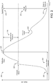
- FIG. 2 shows an illustration of an exemplary pulse waveform signal 200 depicting how the pressure in a radial artery changes over the course of a single heartbeat, or cardiac cycle.
- a cardiac cycle consists of two primary periods: diastole and systole. During diastole, the ventricular musculature is relaxed, and the blood pressure in the outlying vasculature, such as the radial artery, is low, as indicated at 205 (diastolic pressure).
- the ventricular musculature contracts, forcing blood into the vasculature, which increases the vascular blood pressure up to a maximum value, known as the systolic pressure, as indicated at 210.
- the general, periodic wave form of the pulse may be identifiable.
- a pulse rate may be calculated based on the frequency of peaks and troughs (and/or zero-crossing events) within the pulse waveform signal, and then the pulse pressure 215 may be calculated based on the amplitude of the pulse waveform signal.
- the systolic and diastolic pressures may be calculated.
- pulse waveform signal with a high resolution and high quality, additional useful information may be extracted and used to develop a more complete model of an individual's cardiovascular health.
- the periodicity of the pulse waveform signal allows for a significant number of data points to be accumulated in a relatively short period of time, thus enabling the extraction of pulse waveform signal characteristics with significant clinical importance.
- the forward wave represents the pulse wave generated by the heart contracting.
- the reflected wave represents the pulse wave reflecting back to the heart.
- the dicrotic notch shown at 230, is a small increase in blood pressure which occurs when ventricular blood pressure drops and the semilunar valves close. The physical motion of the aortic valve closing creates a small pulse which travels through the radial artery and registers as a pressure increase.
- the difference in magnitude between the forward wave pressure and total systolic pressure is known as the augmentation pressure, as indicated at 235.
- the augmentation pressure and pulse pressure can be used to calculate a value known as the augmentation index, which is frequently used as an indicator of cardiovascular health, particularly as it applies to arterial stiffness.
- the duration between the beginning of systole (wherein the radial artery pressure begins to increase) and the arrival of the reflected wave is indicated at 240 as the time to wave reflection.
- This value is inversely proportional to arterial stiffness. Highly elastic (healthy) blood vessels take longer to reflect a pulse wave, while stiff blood vessels reflect the pulse quickly. In an individual with stiff arteries, the time to wave reflection will be reduced and the reflected wave will arrive at the radial artery much closer to the forward wave. As such, the two waves will combine to a greater extent, and result in a much sharper pressure "peak” observable on the waveform. As the time to wave reflection decreases, the systolic pressure increases, as less of the forward wave's pressure dissipates by the time it combines with the reflected wave.
- Pulse waveform signals with high signal quality can therefore be very clinically useful, as they allow a clinician to approximately determine a patient's arterial stiffness.
- the parameters defining signal quality are application-dependent. Features relevant to successful estimation of signal quality may change depending on what physiological parameters are going to be extracted from the signal downstream in the processing pipeline. Similarly, thresholds for minimum allowable signal quality may also change. As described with reference to pulse waveform signal 200, a relatively low signal quality may be adequate for basic parameters, such as heart rate. More descriptive parameters, such as augmentation pressure and time to wave reflection, may require a higher signal quality in order for the relevant pulse pressure wave features to be extracted and quantified. As such, determining the signal quality of a pulse waveform signal is an important initial step for a heart monitoring device.
- FIG. 3 shows four examples of signal quality for a seven-second window of a photoplethysmogram (PPG) signal (e.g., received from an optical pulse sensing device).
- PPG photoplethysmogram
- Plot 300 includes a pulse waveform signal of excellent signal quality, wherein all beats can be easily visually identified.
- Plot 310 includes a pulse waveform signal of good signal quality, wherein more than half of beats, but not all beats can be visually identified.
- Plot 320 includes a pulse waveform signal of mediocre signal quality, wherein fewer than half, but more than one beat can be visually identified.
- plot 330 includes a pulse waveform signal of poor signal quality, wherein one or fewer beats can be visually identified.
- the pulse waveform signal is entirely preserved in plot 300, and is preserved to lessening degrees as signal quality decreases.
- the raw pulse waveform signal can be manipulated and conditioned to remove noise artifacts, incorrect or inconsistent sensor placement cannot be overcome by mere data processing.
- Both optical and pressure based sensors require correct sensor placement in order to output a signal representative of the pulse waveform signal, regardless of signal resolution.
- a radial tonometer such as satellite device 14 shown in FIG. 1 , needs to be placed directly above the radial artery, between the radius and the flexor carpi radialis tendon, in order for radial artery pressure changes to be conducted to a pressure sensor within the tonometer.
- the signal quality of the pulse waveform signal may be leveraged to augment initial sensor positioning by providing user feedback indicative of confidence that the sensor is placed in the correct sensor position.
- this feedback may decrease the time needed to correctly place the sensor, leading to a more pleasing user experience. Over time, a user may thus learn proper positioning based on the positional feedback, further decreasing placement time. Correct sensor placement will increase the quality of pulse waveform signals, thereby allowing for the calculation of more accurate and more precise cardiovascular parameters.
- a classifier cascade may be utilized to progressively determine signal quality.
- the classifier cascade may be organized such that an initial classifier with a low false-negative rate (high signal acceptance rate) is applied to an initial data window. In this way, some low-quality signals are rejected without falsely rejecting high-quality signals. If the signal is accepted, a larger window of data is subjected to a classifier with a lower false-positive rate (higher signal rejection rate). This process may be repeated with increasingly precise classifiers at each stage. If a signal is rejected, the cascade begins anew at the initial classifier with a new initial data window. In this way, the classifier cascade vets good signals with increasing confidence at each successive classifier.
- FIG. 4 shows an example pulse pressure signal 400, illustrated as a pressure (amplitude) over time
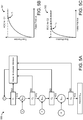
- FIG. 5A shows a flow chart for an example classifier cascade.
- the pulse pressure signal may comprise a plurality of samples, and may be divided into windows of various lengths, the data windows comprising a number of samples proportionate to the length of the data window.
- the data windows (1), (2), (3), and (4) may have increasing lengths.
- data window (1) may represent 0.25 seconds of pulse pressure signal 400
- data window (2) may represent 0.5 seconds of the pulse pressure signal
- data window (3) may represent 1 second of pulse pressure signal
- data window (4) may represent 2 seconds of pulse pressure signal.
- the classifier cascade comprises four classifiers (C 1 , C 2 , C 3 , and C 4 ), but more or fewer classifiers may be used in other examples. Further, the length and number of windows, and/or the number and stringency of classifiers may be varied over time to improve accuracy and/or for providing user feedback.
- the classifier cascade may be trained through machine-learning to identify pulse waveform signals, and may further be trained to recognize signal features that are characteristic of pulse waveform signals of varying quality.
- the classifier cascade may be trained to extract one or more signal features from a pulse waveform signal window, and may further be trained to assign a signal quality index (SQI) to a pulse waveform signal window based on the one or more extracted signal features.
- SQL signal quality index
- Signal features may include, but are not limited to, a slope of a linear signal model (i.e., the value of the slope [a] after fitting a linear model [a]t + [b] to the signal window); the maximum non-initial autocorrelation peak (where peaks may be defined as any index [t] such that x[t-1] ⁇ x[t] and x[t+1] ⁇ x[t]); the number of autocorrelation peaks; the signal standard deviation; the peak to peak amplitude (max-min) of the signal; the spectral energy ratio (high frequencies to low frequencies, where the sum of the absolute values of the values in the upper half of the spectrum are divided by the same for the lower half); the number of signal peaks; the location of first (non-initial) peak in autocorrelation; and/or the mean amplitude of the original signal.
- a slope of a linear signal model i.e., the value of the slope [a] after fitting a linear model [a]t + [b] to
- Classifier features may additionally include the presence or absence of known morphological landmarks in the pressure waveform, such as those shown in FIG. 2 .
- the same set of features may be used in every stage of the cascade, or different sets of features may be used.
- all of the signal features referred to are of the same type and may be combined through gradient-boosted mixtures of decision trees in the machine-learning process, other types of features may be used in addition to or as an alternative to those listed.
- more time and computational effort may be used on longer data windows than on shorter, initial data windows.
- more complex features may be used for downstream classifiers, while less complex features may be used for initial classifiers.
- more complex feature families which may utilize additional computational resources, such as spectral, wavelet, and/or autoregressive features may be used, and/or the same feature families may be used with additional parameters (e.g., a mixture of a larger number of trees and/or deeper trees).
- the signal fed to the classifier cascade may be raw or pre-processed.
- the signal may be passed through one or more filters, such as a bandpass or motion filter, may be passed through an initial vetting stage to ensure the pulse waveform signal comprises an initial signal characteristic, may be divided into data windows (overlapping and/or non-overlapping), etc. prior to any data being provided to the initial classifier.
- a first data window (1) is provided to the first classifier C 1 .
- Classifier C 1 is used to determine whether data window (1) meets a threshold that is representative of correct pulse sensing device placement.
- the threshold for classifier C 1 may be selected at a point approaching a 100% true-positive rate, but with a potentially high false-positive rate, as shown by the sample receiver operating characteristic (ROC) curve 501 and threshold selection (Ti) for classifier C 1 depicted in FIG. 5B . If data window (1) does not meet threshold T 1 , the data window is rejected, and a new, subsequent data window (1) is provided to Classifier C 1 .
- ROC sample receiver operating characteristic
- the concatenated window (S 1-2 ) comprises the samples for both data window (1) and data window (2). Concatenated window (S 1-2 ) is then provided to second classifier C 2 .
- the threshold for classifier C 2 may also be selected at a point approaching a 100% true-positive rate, but with a lower false-positive rate than for classifier C 1 , as shown by the sample receiver operating characteristic (ROC) curve 502 and threshold selection (T 2 ) for classifier C 2 depicted in FIG. 5C . If concatenated window (S 1-2 ) does not meet threshold T 2 , the data window is rejected, and a new, subsequent data window (1) is provided to classifier C 1 .
- ROC sample receiver operating characteristic
- Concatenated window (S 1-2 ) does meet threshold T 2 , subsequent samples are added to the data window until data window (3) is fully received from the pulse sensing device.
- Concatenated window (S 1-3 ) thus comprises the samples for data windows (1), (2), and (3), and is provided to classifier C 3 .
- Classifier C 3 also may have a true-positive rate approaching 100%, but with a lower false positive rate than for classifier C 2 . If concatenated window (S 1-3 ) does not meet the threshold for classifier C 3 , the data window is rejected, and a new, subsequent data window (1) is provided to classifier C 1 .
- Concatenated window (S 1-4 ) thus comprises the samples for data windows (1), (2), (3), and (4), and is provided to classifier C 4 .
- Classifier C 4 also may have a true-positive rate approaching 100%, but with a lower false positive rate than for classifier C 3 . If concatenated window (S 1-4 ) does not meet the threshold for classifier C 4 , the data window is rejected, and a new, subsequent data window (1) is provided to classifier C 1 . If concatenated window (S 1-4 ) does meet the threshold for classifier C 4 , concatenated window (S 1-4 ) is accepted, and the pulse waveform signal may be used in downstream calculations of cardiovascular parameters.
- An advantage of using cascading classifiers with regard to pulse detection is that there is a reduced latency on returned data.
- This may enable an interactive feature for providing user feedback. For example, as a user attempts to place a pulse pressure sensor in place over the radial artery, initial rapid classifiers may indicate whether the signal is good or bad. This feedback may be given to the user to augment sensor placement, by indicating if the sensor needs to be moved significantly (bad signal), slightly (moderate quality signal), or not at all (good signal). Gradients of feedback may be used to indicate if the signal quality is improving or declining.
- FIG. 6 shows a flow chart for an example method 600 of providing user feedback regarding placement of a pulse sensing device using a classifier cascade, such as the classifier cascade depicted in FIG. 5A .
- Method 600 may be applied to a wearable cardiovascular monitoring device.
- user feedback will be described in terms of visual cues provided by a feedback machine, for example, a display device or set of LEDs at the wearable cardiovascular monitoring device.
- a feedback machine for example, a display device or set of LEDs at the wearable cardiovascular monitoring device.
- other forms of user feedback may be provided through one or more feedback machines, such as audio cues, haptic cues, combinations of cues, etc. and/or different forms of user feedback may be provided at different stages of progression through the classifier cascade.
- method 600 includes receiving a pulse waveform signal from a pulse sensing device.
- a pulse waveform signal may be received from an optical pulse sensing device, an arterial tonometer, etc.
- the pulse waveform signal may be pre-processed prior to being received.
- one or more filters may be applied to a raw pulse waveform signal received directly from the pulse sensing device.
- method 600 includes computer-determining whether the pulse waveform signal comprises an initial signal characteristic.
- an initial signal characteristic may include a periodicity or amplitude representative of a pulse waveform signal. In this way, the absence of a pulse waveform signal can be identified, distinguished from a low-quality pulse waveform signal, and appropriate user-feedback can be provided.
- method 600 proceeds to 615.
- method 600 includes providing user feedback indicating that the pulse sensing device needs to be relocated towards a target sensing location. For example a flashing red signal may be output via the feedback machine.
- method 600 proceeds to 620, and includes providing a first data window, comprising a first number of samples, of the pulse waveform signal to a first classifier.
- method 600 includes computer-analyzing the first data window of the pulse waveform signal to determine whether the first data window is representative of correct pulse sensing device placement. For example, a signal quality index of the first data window may be determined based on one or more signal characteristics of the data window, and then compared to a first threshold. If it is determined that the first data window does not indicate correct pulse sensing device placement, method 600 proceeds to 630, and includes providing user feedback indicating incorrect pulse sensing device placement. For example, an unblinking red light may be output via the feedback machine.
- method 600 includes providing a new data window of the pulse waveform signal, comprising the first number of samples, to the first classifier. The new data window may then be computer analyzed with the first classifier, and the method may then continue as described.
- method 600 proceeds to 640, and includes providing user feedback indicating an initial level of confidence that the pulse sensing device is correctly placed. For example, a flashing yellow light may be output via the feedback machine.
- method 600 includes providing a second data window of the pulse waveform signal, comprising a second number of samples, to a second classifier.
- the second data window may comprise a second number of samples larger than the first number of samples, and the samples in the second data window may include all of the samples in the first data window. Further, the second classifier may have a lower false-positive rate than the first classifier.
- method 600 includes computer-analyzing the second data window of the pulse waveform signal to determine whether the first data window is representative of correct pulse sensing device placement. If it is determined that the second data window does not indicate correct pulse sensing device placement, method 600 proceeds to 630, and includes providing user feedback indicating incorrect pulse sensing device placement, such as an unblinking red light. Continuing at 635, method 600 includes providing a new data window of the pulse waveform signal, comprising the first number of samples, to the first classifier, as described.
- method 600 proceeds to 655, and includes providing user feedback indicating an increased level of confidence that the pulse sensing device is correctly placed. For example, the flashing yellow light may be output via the feedback machine with an increased flashing frequency.
- method 600 includes determining whether the current data window has been computer-analyzed by a final classifier in the classifier cascade. If the current data window has not been computer-analyzed by a final classifier, method 600 proceeds to 665, and includes providing an N+1 st window of the pulse waveform signal to an N+1 st classifier.
- a third data window may comprise a third number of samples, larger than the second number of samples, and the samples in the third data window may include all of the samples in the second data window (including all of the samples in the first data window). Further, the third classifier may have a lower false-positive rate than the second classifier.
- method 600 proceeds to 630, and includes providing user feedback indicating incorrect pulse sensing device placement.
- method 600 returns to 655, and includes providing user feedback indicating an increased level of confidence that the pulse sensing device is correctly placed (e.g., increasing the frequency of the flashing yellow light).
- method 600 includes providing sequentially larger data windows of the pulse waveform signal to increasingly stringent classifiers.
- method 600 proceeds to 675, and includes providing user feedback indicating that the pulse sensing device is correctly placed at the target sensing location. For example an unblinking green light may be output via the feedback machine.
- method 600 includes computer-calculating a cardiovascular parameter based on the pulse waveform signal, such as a heart rate, or other parameters described herein.
- FIG. 7 shows a flow chart for an example method 700 enabling signal quality estimation without motion filtering, and without beat segmentation.
- the method is applicable to wearable cardiovascular monitors worn by individuals who are standing, running, walking, or performing other ambulatory tasks.
- Method 700 utilizes the quasi-periodic, highly stereotyped nature of the pulse waveform signal without the need for beat segmentation, and may be applied to pulse waveform signals received from a variety of pulse sensing devices, including optical sensors and tonometers.
- method 700 includes receiving a pulse waveform signal from a pulse sensing device.
- a pulse waveform signal may be received from an optical pulse sensing device, an arterial tonometer, etc.
- method 700 includes computer-processing a window of the pulse waveform signal including n samples.
- the received pulse waveform signal may be a raw pulse waveform signal or a pre-processed pulse waveform signal.
- the raw pulse waveform signal is not subject to motion filtering.
- the pulse waveform signal may be downsampled and divided into windows.
- the pulse waveform signal may be divided into seven-second non-overlapping windows.
- the raw pulse waveform signal may be acquired at a high sampling rate, such that a window includes a number of samples greater than n.
- a 1000 Hz pulse waveform signal may be downsampled to 15 Hz. For a resulting 7 second window, n would thus equal 105 samples.
- method 700 includes computer-quantizing each of the n samples of the data window into an integer ranging from 1 to r.
- the data window Prior to computer-quantizing the n samples, the data window may be locally normalized, for example on the interval [0, 1].
- the value of r is based on a bit depth selected for quantization. For example, a selected bit depth of 4 yields a possible 16 integer values.
- Each of the n samples within the window may then be assigned one of the discrete values ranging from 1 to 16 (or one of the discrete values ranging from 0000 to 1111 in binary).
- method 700 includes establishing a transition matrix for the window.
- the transition matrix may include r rows and r columns.
- Each cell of the transition matrix may indicate a frequency within the window that a sample m, having the quantized row value is sequentially followed in the data window by a sample m + 1 having the quantized column value.
- the cell [1, 1] indicates a frequency that a sample m (e.g., the 42 nd sample in the downsampled window) having a value of 1 is sequentially followed in the data window by a sample m + 1 (e.g., the 43 rd sample in the downsampled window) also having a value of 1.
- the cell [1, 2] indicates a frequency that a sample m having a value of 1 is sequentially followed in the data window by a sample m + 1 having a value of 2.
- the transition matrix may then be normalized to yield the probability distribution p ( x n +1
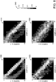
- FIG. 8 shows example sample-to-sample transition matrices for four data windows of varying signal quality.
- matrix 800 is derived from a pulse waveform signal of excellent signal quality
- matrix 810 is derived from a pulse waveform signal of good signal quality
- matrix 820 is derived from a pulse waveform signal of mediocre signal quality
- matrix 830 is derived from a pulse waveform signal of poor signal quality.
- the pulse waveform signal is intrinsically asymmetric, as can be seen for matrix 800. Further, in a high-quality signal, the highest probabilities lie on the diagonal, as m + 1 is likely to be similar to m. As the signal quality decreases, the matrices become more symmetric, and the sample-to-sample transition probability becomes more broadly and more randomly dispersed throughout the matrix (e.g., matrix 830). Motion signals are quasi-periodic, and thus increasing signal contamination from motion artifacts is observable.
- method 700 includes computer-determining a signal quality index of the window based on the transition matrix.
- a classifier may be trained via machine learning, in similar fashion to the classifier training discussed with reference to FIGS. 4-6 .
- an example method for classifying may include the employment of a late fusion approach with a linear support vector machine (SVM) trained for regression (SVR) on the sample-to-sample transition matrices using signal quality indexes as labels.
- the SVM may be implemented using L2-loss regularization.
- the prediction output of the SVR may then be fused with the remaining feature set for signal quality prediction. In each fold, the SVR may be trained on training data alone, but features may be extracted for all training and test data to allow for training of a 2 nd -stage ML algorithm.
- method 700 includes excluding the data window from downstream cardiovascular parameter calculations requiring a signal quality index greater than the computer-determined signal quality index for the window.
- method 700 includes including the data window in downstream cardiovascular parameter calculations requiring a signal quality index lower than the computer-determined signal quality index for the window.
- a good-but-not-excellent data window such as the data window represented by matrix 810 may be adequate for calculating parameters such as heart rate, but inadequate for calculating parameters such as augmentation pressure.
- the sample-to-sample transition matrices may be combined with other signal quality features to produce a combined signal quality index.
- features that are sensitive to discrete motion events e.g., autocorrelation metrics
- both periodic and aperiodic signal contaminants may be robustly identified.
- method 700 may be fused with one or more classifier cascades, and one or more beat-template matching algorithms.
- a classification and regression tree may be trained using the features described above, to estimate a signal quality index for a data window.
- the estimated signal quality index based on one or more feature sets may be used to provide feedback for conditioning the pulse waveform signal.
- Signal conditioning e.g., motion filtering
- a signal quality index may then be derived for the conditioned signal, and the conditioning algorithms adapted or adjusted based on the feedback.
- the methods and processes described herein may be tied to a computing system of one or more computing devices.
- such methods and processes may be implemented as a computer-application program or service, an application-programming interface (API), a library, and/or other computer-program product.
- FIG. 1 shows one, non-limiting example of a sensor-and-logic system to enact the methods and processes described herein.
- these methods and process may also be enacted on sensor-and-logic systems of other configurations and form factors, as shown schematically in FIG. 9 .
- FIG. 9 schematically shows a form-agnostic sensor-and-logic system 910 that includes a sensor suite 912 operatively coupled to a compute system 914.
- the compute system includes a logic machine 916 and a data-storage machine 918.
- the compute system is operatively coupled to a display subsystem 920, a communication subsystem 922, an input subsystem 924, and/or other components not shown in FIG. 9 .
- Logic machine 916 includes one or more physical devices configured to execute instructions.
- the logic machine may be configured to execute instructions that are part of one or more applications, services, programs, routines, libraries, objects, components, data structures, or other logical constructs. Such instructions may be implemented to perform a task, implement a data type, transform the state of one or more components, achieve a technical effect, or otherwise arrive at a desired result.
- Logic machine 916 may include one or more processors configured to execute software instructions. Additionally or alternatively, the logic machine may include one or more hardware or firmware logic machines configured to execute hardware or firmware instructions. Processors of the logic machine may be single-core or multi-core, and the instructions executed thereon may be configured for sequential, parallel, and/or distributed processing. Individual components of a logic machine optionally may be distributed among two or more separate devices, which may be remotely located and/or configured for coordinated processing. Aspects of a logic machine may be virtualized and executed by remotely accessible, networked computing devices in a cloud-computing configuration.
- Data-storage machine 918 includes one or more physical devices configured to hold instructions executable by logic machine 916 to implement the methods and processes described herein. When such methods and processes are implemented, the state of the data-storage machine may be transformed-e.g., to hold different data.
- the data-storage machine may include removable and/or built-in devices; it may include optical memory (e.g., CD, DVD, HD-DVD, Blu-Ray Disc, etc.), semiconductor memory (e.g., RAM, EPROM, EEPROM, etc.), and/or magnetic memory (e.g., hard-disk drive, floppy-disk drive, tape drive, MRAM, etc.), among others.
- the data-storage machine may include volatile, nonvolatile, dynamic, static, read/write, read-only, random-access, sequential-access, location-addressable, file-addressable, and/or content-addressable devices.
- Data-storage machine 918 includes one or more physical devices. However, aspects of the instructions described herein alternatively may be propagated by a communication medium (e.g., an electromagnetic signal, an optical signal, etc.) that is not held by a physical device for a finite duration.
- a communication medium e.g., an electromagnetic signal, an optical signal, etc.
- logic machine 916 and data-storage machine 918 may be integrated together into one or more hardware-logic components.
- hardware-logic components may include field-programmable gate arrays (FPGAs), program- and application-specific integrated circuits (PASIC / ASICs), program- and application-specific standard products (PSSP / ASSPs), system-on-a-chip (SOC), and complex programmable logic devices (CPLDs), for example.
- FPGAs field-programmable gate arrays
- PASIC / ASICs program- and application-specific integrated circuits
- PSSP / ASSPs program- and application-specific standard products
- SOC system-on-a-chip
- CPLDs complex programmable logic devices
- Display subsystem 920 may be used to present a visual representation of data held by data-storage machine 918. This visual representation may take the form of a graphical user interface (GUI). As the herein described methods and processes change the data held by the storage machine, and thus transform the state of the storage machine, the state of display subsystem 920 may likewise be transformed to visually represent changes in the underlying data.
- Display subsystem 920 may include one or more display subsystem devices utilizing virtually any type of technology. Such display subsystem devices may be combined with logic machine 916 and/or data-storage machine 918 in a shared enclosure, or such display subsystem devices may be peripheral display subsystem devices. Display 34 of FIG. 1 is an example of display subsystem 920.
- Communication subsystem 922 may be configured to communicatively couple compute system 914 to one or more other computing devices.
- the communication subsystem may include wired and/or wireless communication devices compatible with one or more different communication protocols.
- the communication subsystem may be configured for communication via a wireless telephone network, a local- or wide-area network, and/or the Internet.
- Communication suite 36 of FIG. 1 is an example of communication subsystem 922.
- Input subsystem 924 may comprise or interface with one or more user-input devices such as a keyboard, touch screen, button, dial, joystick, or switch.
- the input subsystem may comprise or interface with selected natural user input (NUI) componentry.
- NUI natural user input
- Such componentry may be integrated or peripheral, and the transduction and/or processing of input actions may be handled on- or off-board.
- NUI componentry may include a microphone for speech and/or voice recognition; an infrared, color, stereoscopic, and/or depth camera for machine vision and/or gesture recognition; a head tracker, eye tracker, accelerometer, and/or gyroscope for motion detection and/or intent recognition.
- Push button 48 of FIG. 1 is an example of input subsystem 924.
- Sensor suite 912 may include one or more different sensors- e.g ., pulse sensing device 926, a touch-screen sensor, push-button sensor, microphone, visible-light sensor, ultraviolet sensor, ambient-temperature sensor, contact sensors, and/or GPS receiver-as described above with reference to FIG. 1 .
- Sensor suite 912 may include motion sensor suite 928.
- Motion sensor suite 928 may include one or more of an accelerometer, gyroscope, magnetometer, or other suitable motion detectors.
- pulse sensing device 926 may include one or more arterial tonometers and/or one or more optical pulse sensing devices.
- Compute system 914 may include pulse sensing device control subsystem 930, which may be communicatively coupled to logic machine 916 and data-storage machine 918.
- the tonometer may include one or more pressure transducers comprising one or more piezo-resistive sensors configured to provide absolute pressure signals to compute system 914 via an analog-to-digital converter.
- the pressure transducer may be configured to transduce pressure waves from blood vessels 935 (e.g., a radial artery) through the skin 940 of the user.
- the optical pulse sensing device may include one or more optical sources comprising one or more LED emitters, and one or more optical sensors comprising one or more photodiodes matched to detect light at frequencies that are based on the frequencies of light output by the optical source.
- the optical source(s) may be configured to illuminate one or more blood vessels 935 through the skin 940 of the user, and the optical sensor(s) may be configured to measure illumination reflected from or transmitted through blood vessels 935.
- Pulse sensing device control subsystem 930 may further process the raw signals to determine pulse waveform signal quality, heart rate, blood pressure, caloric expenditures, etc. Processed signals may be stored and output via compute system 914, for example via display subsystem 920 and/or communication subsystem 922. Control signals sent to pulse sensing device 926 may be based on signals derived from sensor suite 912, information stored in data-storage machine 918, input received from communication subsystem 922, input received from input subsystem 924, etc.
- a method for a wearable cardiovascular monitoring device comprises: receiving a pulse waveform from a pulse sensing device; using a first classifier, computer-analyzing a first data window of the pulse waveform signal, comprising a first number of samples; responsive to computer-analysis of the first data window indicating correct pulse sensing device placement, providing user feedback, via a feedback machine, indicating an initial level of confidence that the pulse sensing device is correctly placed; using a second classifier, computer-analyzing a second data window of the pulse waveform signal, comprising a second number of samples larger than the first number of samples; and responsive to computer-analysis of the second data window indicating correct pulse sensing device placement, providing user feedback, via the feedback machine, indicating an increased level of confidence that the pulse sensing device is correctly placed.
- the method further comprises: using a final classifier, computer-analyzing a final data window of the pulse waveform signal, having a final number of samples larger than the second number of samples; and responsive to computer-analysis of the final data window indicating correct pulse sensing device placement, providing user feedback, via the feedback machine, indicating that the pulse sensing device is correctly placed at a target sensing location.
- the method further comprises: responsive to computer-analysis of the final data window indicating correct pulse sensing device placement, computer-calculating a cardiovascular parameter based on the pulse waveform signal.
- the samples comprised in the second data window comprise all of the samples comprised in the first data window
- the samples comprised in the final data window comprise all of the samples comprised in the second data window.
- the second classifier has a lower false-positive rate than the first classifier
- the final classifier has a lower false-positive rate than the second classifier.
- the method further comprises: responsive to computer-analysis of the first, second, or final data window not indicating correct pulse sensing device placement, providing user feedback, via the feedback machine, indicating incorrect pulse sensing device placement.
- the method further comprises: responsive to computer-analysis of the first, second, or final data window not indicating correct pulse sensing device placement, computer-analyzing with the first classifier a new data window of the pulse waveform signal, comprising the first number of samples.
- the method further comprises: computer-determining whether the pulse waveform signal comprises an initial signal characteristic; responsive to the pulse waveform signal comprising the initial signal characteristic, providing a new data window to the first classifier comprising the first number of samples of the pulse waveform signal; and responsive to the pulse waveform signal not comprising the initial signal characteristic, providing user feedback, via the feedback machine, indicating that the pulse sensing device needs to be relocated towards a target sensing location.
- a method for a wearable cardiovascular device comprises: receiving a pulse waveform signal from a pulse sensing device; computer-processing a window of the pulse waveform signal including n samples; computer-quantizing each of the n samples into an integer ranging from 1 to r ; establishing a transition matrix for the window, the transition matrix including r rows and r columns, wherein each cell of the transition matrix indicates a frequency within the window that a sample m, having a quantized row value of r, is followed by a sample m + 1 having a quantized column value of r ; and computer-determining a signal quality index of the window based on the transition matrix.
- the n samples are downsampled from a raw pulse waveform signal.
- the raw pulse waveform signal is bandpass filtered, but not motion filtered prior to downsampling.
- the raw pulse waveform signal is output by an optical pulse sensing device.
- the raw pulse waveform signal is output by an arterial tonometer.
- the n samples are locally normalized prior to being quantized.
- the window is excluded from downstream cardiovascular parameter calculations requiring a signal quality index greater than the computer-determined signal quality index for the window.
- the window is included in downstream cardiovascular parameter calculations requiring a signal quality index lower than the computer-determined signal quality index for the window.
- a wearable cardiovascular monitoring device comprises: a pulse sensing device; a feedback machine; and a pulse sensing device control subsystem, configured to: receive a pulse waveform signal from the pulse sensing device; using a first classifier, computer-analyze a first data window of the pulse waveform signal, the first data window comprising a first number of samples; responsive to computer-analysis of the first data window indicating correct pulse sensing device placement, provide user feedback, via the feedback machine, indicating an initial level of confidence that the pulse sensing device is correctly placed; using a second classifier having a lower false-positive rate than the first classifier, computer-analyze a second data window of the pulse waveform signal, the second data window comprising a second number of samples, larger than the first number of samples; and responsive to computer-analysis of the second data window indicating correct pulse sensing device placement, provide user feedback, via the feedback machine, indicating an increased level of confidence that the pulse sensing device is correctly placed.
- the pulse sensing device control subsystem is further configured to: using a final classifier having a lower false-positive rate than the second classifier, computer-analyze a final data window of the pulse waveform signal, having a final number of samples larger than the second number of samples; responsive to computer-analysis of the final data window indicating correct pulse sensing device placement, provide user feedback, via the feedback machine, indicating that the pulse sensing device is correctly placed; and responsive to computer-analysis of the final data window indicating correct pulse sensing device placement, computer-calculate a cardiovascular parameter based on the pulse waveform signal.
- the samples comprised in the second data window comprise all of the samples in the first data window, and the samples comprised in the final data window include all of the samples comprised in the second data window.
- the pulse sensing device control subsystem is further configured to: responsive to computer-analysis of the first, second, or final data window not indicating correct pulse sensing device placement, provide user feedback, via the feedback machine, indicating incorrect pulse sensing device placement; and responsive to computer-analysis of the first, second, or final data window indicating incorrect pulse sensing device placement, computer-analyze with the first classifier a new data window of the pulse waveform signal, the new data window comprising the first number of samples.
Landscapes
- Health & Medical Sciences (AREA)
- Life Sciences & Earth Sciences (AREA)
- Engineering & Computer Science (AREA)
- Physics & Mathematics (AREA)
- Public Health (AREA)
- Surgery (AREA)
- Veterinary Medicine (AREA)
- General Health & Medical Sciences (AREA)
- Animal Behavior & Ethology (AREA)
- Biophysics (AREA)
- Pathology (AREA)
- Biomedical Technology (AREA)
- Heart & Thoracic Surgery (AREA)
- Medical Informatics (AREA)
- Molecular Biology (AREA)
- Physiology (AREA)
- Cardiology (AREA)
- Artificial Intelligence (AREA)
- Signal Processing (AREA)
- Computer Vision & Pattern Recognition (AREA)
- Psychiatry (AREA)
- Evolutionary Computation (AREA)
- Fuzzy Systems (AREA)
- Mathematical Physics (AREA)
- Vascular Medicine (AREA)
- Measuring Pulse, Heart Rate, Blood Pressure Or Blood Flow (AREA)
Claims (13)
- Verfahren (600) für eine am Körper tragbare kardiovaskuläre Überwachungsvorrichtung (10), das umfasst:Empfangen (605) einer Pulswellenform von einer Pulserfassungsvorrichtung (926);unter Verwendung (620) eines ersten Klassifizierers (C1), Computeranalysieren eines ersten Datenfensters (1) des Pulswellenformsignals, das eine erste Anzahl von Abtastungen umfasst;in Antwort darauf, dass Computeranalyse (625) des ersten Datenfensters (1) korrekte Pulserfassungsvorrichtungs- (926) Platzierung angibt, Bereitstellen von Benutzerrückkopplung, über eine Rückkopplungsmaschine, die ein anfängliches Konfidenzniveau angibt (640), dass die Pulserfassungsvorrichtung korrekt platziert ist;dadurch gekennzeichnet, dassdas Verfahren weiter umfasst:unter Verwendung (645) eines zweiten Klassifizierers (C2), der eine niedrigere Falschpositivrate als der erste Klassifizierer (C1) aufweist, Computeranalysieren eines zweiten Datenfensters (2) des Pulswellenformsignals, wobei das zweite Datenfenster eine zweite Anzahl von Abtastungen umfasst, die größer als die erste Anzahl von Abtastungen ist; undin Antwort darauf, dass Computeranalyse (650) des zweiten Datenfensters korrekte Pulserfassungsvorrichtungs- (926) Platzierung angibt, Bereitstellen von Benutzerrückkopplung, über die Rückkopplungsmaschine, die ein erhöhtes Konfidenzniveau angibt (655), dass die Pulserfassungsvorrichtung (926) korrekt platziert ist.
- Verfahren (600) nach Anspruch 1, weiter umfassend:unter Verwendung (660) eines finalen Klassifizierers (Cn), der eine niedrigere Falschpositivrate als der zweite Klassifizierer (C2) aufweist, Computeranalysieren eines finalen Datenfensters des Pulswellenformsignals, das eine finale Anzahl von Abtastungen aufweist, die größer als die zweite Anzahl von Abtastungen ist; undin Antwort darauf, dass Computeranalyse (670) des finalen Datenfensters korrekte Pulserfassungsvorrichtungs- (926) Platzierung angibt, Bereitstellen von Benutzerrückkopplung, über die Rückkopplungsmaschine, die angibt (975), dass die Pulserfassungsvorrichtung (926) korrekt an einem Zielerfassungsort platziert ist.
- Verfahren (600) nach Anspruch 2, weiter umfassend:in Antwort darauf, dass Computeranalyse des finalen Datenfensters korrekte Pulserfassungsvorrichtungs- (926) Platzierung angibt, Computerberechnen eines kardiovaskulären Parameters (680) basierend auf dem Pulswellenformsignal.
- Verfahren (600) nach Anspruch 2, wobei die Abtastungen, die in dem zweiten Datenfenster (2) umfasst sind, all die Abtastungen umfassen, die in dem ersten Datenfenster (1) umfasst sind, und wobei die Abtastungen, die in dem finalen Datenfenster umfasst sind, all die Abtastungen umfassen, die in dem zweiten Datenfenster (2) umfasst sind.
- Verfahren (600) nach Anspruch 1, weiter umfassend:in Antwort darauf, dass Computeranalyse des ersten, zweiten oder finalen Datenfensters nicht korrekte Pulserfassungsvorrichtungsplatzierung angibt, Bereitstellen von Benutzerrückkopplung, über die Rückkopplungsmaschine, die unkorrekte Pulserfassungsvorrichtungsplatzierung angibt (630).
- Verfahren (600) nach Anspruch 5, weiter umfassend:in Antwort darauf, dass Computeranalyse des ersten, zweiten oder finalen Datenfensters nicht korrekte Pulserfassungsvorrichtungsplatzierung angibt, Computeranalysieren (635) eines neuen Datenfensters des Pulswellenformsignals, das die erste Anzahl von Abtastungen umfasst, mit dem ersten Klassifizierer.
- Verfahren (600) nach Anspruch 1, weiter umfassend:Computerbestimmen (610), ob das Pulswellenformsignal eine Anfangssignalcharakteristik umfasst;in Antwort darauf, dass das Pulswellenformsignal die Anfangssignalcharakteristik umfasst, Bereitstellen (620) eines neuen Datenfensters an den ersten Klassifizierer (C1), das die erste Anzahl von Abtastungen des Pulswellenformsignals umfasst; undin Antwort darauf, dass das Pulswellenformsignal nicht die Anfangssignalcharakteristik umfasst, Bereitstellen von Benutzerrückkopplung, über die Rückkopplungsmaschine, die angibt (615), dass die Pulserfassungsvorrichtung (926) zu einem Zielerfassungsort hin umverortet werden muss.
- Am Körper tragbare kardiovaskuläre Überwachungsvorrichtung (10), umfassend:eine Pulserfassungsvorrichtung (926);eine Rückkopplungsmaschine; undein Pulserfassungsvorrichtungssteuerungssubsystem (930), das dafür eingerichtet ist:eine Pulswellenform von der Pulserfassungsvorrichtung (926) zu empfangen;unter Verwendung eines ersten Klassifizierers (C1) ein erstes Datenfenster des Pulswellenformsignals zu computeranalysieren, wobei das erste Datenfenster eine erste Anzahl von Abtastungen umfasst;in Antwort darauf, dass Computeranalyse (625) des ersten Datenfensters korrekte Pulserfassungsvorrichtungs- (926) Platzierung angibt, Benutzerrückkopplung, über die Rückkopplungsmaschine, bereitzustellen, die ein anfängliches Konfidenzniveau angibt (640), dass die Pulserfassungsvorrichtung korrekt platziert ist;dadurch gekennzeichnet, dass das Pulserfassungsvorrichtungssteuerungssubsystem (930) weiter dafür eingerichtet ist:unter Verwendung eines zweiten Klassifizierers (C2), der eine niedrigere Falschpositivrate als der erste Klassifizierer (C1) aufweist, ein zweites Datenfenster des Pulswellenformsignals zu computeranalysieren, wobei das zweite Datenfenster eine zweite Anzahl von Abtastungen umfasst, die größer als die erste Anzahl von Abtastungen ist; undin Antwort darauf, dass Computeranalyse (650) des zweiten Datenfensters (C2) korrekte Pulserfassungsvorrichtungs- (926) Platzierung angibt, Benutzerrückkopplung, über die Rückkopplungsmaschine, bereitzustellen, die ein erhöhtes Konfidenzniveau angibt (655), dass die Pulserfassungsvorrichtung korrekt platziert ist.
- Am Körper tragbare kardiovaskuläre Überwachungsvorrichtung (10) nach Anspruch 8, wobei das Pulserfassungsvorrichtungssteuerungssubsystem (910) weiter dafür eingerichtet ist:unter Verwendung eines finalen Klassifizierers (665), der eine niedrigere Falschpositivrate als der zweite Klassifizierer (C2) aufweist, ein finales Datenfenster des Pulswellenformsignals zu computeranalysieren, das eine finale Anzahl von Abtastungen aufweist, die größer als die zweite Anzahl von Abtastungen ist;in Antwort darauf, dass Computeranalyse (670) des finalen Datenfensters korrekte Pulserfassungsvorrichtungsplatzierung angibt, Benutzerrückkopplung, über die Rückkopplungsmaschine, bereitzustellen, die angibt (675), dass die Pulserfassungsvorrichtung korrekt platziert ist; undin Antwort darauf, dass Computeranalyse des finalen Datenfensters korrekte Pulserfassungsvorrichtungsplatzierung angibt, einen kardiovaskulären Parameter basierend auf dem Pulswellenformsignal zu computerberechnen.
- Am Körper tragbare kardiovaskuläre Überwachungsvorrichtung (10) nach Anspruch 9, wobei die Abtastungen, die in dem zweiten Datenfenster (C2) umfasst sind, all die Abtastungen in dem ersten Datenfenster (1) umfassen, und wobei die Abtastungen, die in dem finalen Datenfenster umfasst sind, all die Abtastungen umfassen, die in dem zweiten Datenfenster (2) umfasst sind.
- Am Körper tragbare kardiovaskuläre Überwachungsvorrichtung (10) nach Anspruch 9, wobei das Pulserfassungsvorrichtungssteuerungssubsystem (910) weiter dafür eingerichtet ist:in Antwort darauf, dass Computeranalyse des ersten (C1), zweiten (C2) oder finalen Datenfensters (Cn) nicht korrekte Pulserfassungsvorrichtungsplatzierung angibt, Benutzerrückkopplung, über die Rückkopplungsmaschine, bereitzustellen, die unkorrekte Pulserfassungsvorrichtungsplatzierung angibt (630).
- Am Körper tragbare kardiovaskuläre Überwachungsvorrichtung (10) nach Anspruch 11, wobei das Pulserfassungsvorrichtungssteuerungssubsystem (910) weiter dafür eingerichtet ist:in Antwort darauf, dass Computeranalyse des ersten, zweiten oder finalen Datenfensters nicht korrekte Pulserfassungsvorrichtungsplatzierung angibt, ein neues Datenfenster des Pulswellenformsignals mit dem ersten Klassifizierer zu computeranalysieren (635), wobei das neue Datenfenster die erste Anzahl von Abtastungen umfasst.
- Am Körper tragbare kardiovaskuläre Überwachungsvorrichtung (10) nach Anspruch 8, wobei das Pulserfassungsvorrichtungssteuerungssubsystem (910) weiter dafür eingerichtet ist:zu computerbestimmen, ob das Pulswellenformsignal eine Anfangssignalcharakteristik (610) umfasst;in Antwort darauf, dass das Pulswellenformsignal die Anfangssignalcharakteristik umfasst, ein neues Datenfenster (1) an den ersten Klassifizierer (C1) bereitzustellen, das die erste Anzahl von Abtastungen des Pulswellenformsignals umfasst; undin Antwort darauf, dass das Pulswellenformsignal nicht die Anfangssignalcharakteristik umfasst, Benutzerrückkopplung, über die Rückkopplungsmaschine, bereitzustellen, die angibt (615), dass die Pulserfassungsvorrichtung zu einem Zielerfassungsort hin umverortet werden muss.
Applications Claiming Priority (3)
| Application Number | Priority Date | Filing Date | Title |
|---|---|---|---|
| US201562142463P | 2015-04-02 | 2015-04-02 | |
| US14/750,037 US10765331B2 (en) | 2015-04-02 | 2015-06-25 | Wearable pulse sensing device signal quality estimation |
| PCT/US2016/025458 WO2016161227A2 (en) | 2015-04-02 | 2016-04-01 | Wearable pulse sensing device signal quality estimation |
Publications (2)
| Publication Number | Publication Date |
|---|---|
| EP3277162A2 EP3277162A2 (de) | 2018-02-07 |
| EP3277162B1 true EP3277162B1 (de) | 2019-01-02 |
Family
ID=55755737
Family Applications (1)
| Application Number | Title | Priority Date | Filing Date |
|---|---|---|---|
| EP16717027.3A Not-in-force EP3277162B1 (de) | 2015-04-02 | 2016-04-01 | Signalqualitätsbestimmung für am körper tragbare pulsmessvorrichtung |
Country Status (5)
| Country | Link |
|---|---|
| US (1) | US10765331B2 (de) |
| EP (1) | EP3277162B1 (de) |
| CN (1) | CN107580471B (de) |
| TW (1) | TW201642803A (de) |
| WO (1) | WO2016161227A2 (de) |
Families Citing this family (32)
| Publication number | Priority date | Publication date | Assignee | Title |
|---|---|---|---|---|
| WO2016029166A1 (en) * | 2014-08-22 | 2016-02-25 | Thomas Adrian Furness, Iii | Automated diagnosis based at least in part on pulse waveforms |
| US10420515B2 (en) | 2015-06-15 | 2019-09-24 | Vital Labs, Inc. | Method and system for acquiring data for assessment of cardiovascular disease |
| WO2016205414A1 (en) | 2015-06-15 | 2016-12-22 | Vital Labs, Inc. | Method and system for cardiovascular disease assessment and management |
| WO2017096313A1 (en) | 2015-12-02 | 2017-06-08 | Echo Labs, Inc. | Systems and methods for non-invasive respiratory rate measurement |
| WO2018072212A1 (zh) | 2016-10-21 | 2018-04-26 | 华为技术有限公司 | 血压测量设备的校准方法及血压测量设备 |
| US10722125B2 (en) | 2016-10-31 | 2020-07-28 | Livemetric (Medical) S.A. | Blood pressure signal acquisition using a pressure sensor array |
| US10716518B2 (en) | 2016-11-01 | 2020-07-21 | Microsoft Technology Licensing, Llc | Blood pressure estimation by wearable computing device |
| US11000193B2 (en) | 2017-01-04 | 2021-05-11 | Livemetric (Medical) S.A. | Blood pressure measurement system using force resistive sensor array |
| US20180184920A1 (en) * | 2017-01-05 | 2018-07-05 | Livemetric (Medical) S.A. | System and method for providing user feeedback of blood pressure sensor placement and contact quality |
| FR3063628A1 (fr) * | 2017-03-10 | 2018-09-14 | Rhizom | Dispositif et procede de mesure d’un parametre physiologique et apprentissage statistique |
| KR102374990B1 (ko) * | 2017-03-21 | 2022-03-16 | 삼성전자 주식회사 | 피부 관련 정보를 제공하는 방법 및 이를 사용하는 전자 장치 |
| KR102588906B1 (ko) | 2017-12-01 | 2023-10-13 | 삼성전자주식회사 | 생체 신호 품질 평가 장치 및 방법 |
| US11457872B2 (en) | 2017-12-01 | 2022-10-04 | Samsung Electronics Co., Ltd. | Bio-signal quality assessment apparatus and bio-signal quality assessment method |
| CN108186000B (zh) * | 2018-02-07 | 2024-04-02 | 河北工业大学 | 基于心冲击信号与光电信号的实时血压监测系统及方法 |
| JP6815344B2 (ja) * | 2018-03-12 | 2021-01-20 | 京セラ株式会社 | 電子機器、推定システム、推定方法及び推定プログラム |
| JP2019154774A (ja) * | 2018-03-13 | 2019-09-19 | 株式会社東芝 | 生体測定装置、及び生体測定方法 |
| US11311237B2 (en) | 2019-01-28 | 2022-04-26 | Itamar Medical Spry 2021, Limited Partnership | Systems and methods for computationally efficient non-invasive blood quality measurement |
| KR102716673B1 (ko) * | 2019-02-07 | 2024-10-11 | 삼성전자주식회사 | 생체정보 추정 장치 및 방법 |
| CN110416744B (zh) * | 2019-07-08 | 2021-08-24 | 维沃移动通信有限公司 | 一种天线装置、天线控制方法及终端设备 |
| CN110974189A (zh) * | 2019-10-25 | 2020-04-10 | 广州视源电子科技股份有限公司 | 脉搏波的信号质量检测方法及装置、设备、系统 |
| CN113440118A (zh) * | 2020-03-27 | 2021-09-28 | 华为技术有限公司 | 获取ppg信号的方法、装置、终端设备和存储介质 |
| CN111513687B (zh) * | 2020-04-10 | 2024-04-05 | 北京科技大学 | 人体低氧伤害监测预警手环及人体低氧伤害监测预警方法 |
| US11568292B2 (en) * | 2020-06-25 | 2023-01-31 | Textron Innovations Inc. | Absolute and relative importance trend detection |
| US12446833B2 (en) * | 2020-08-26 | 2025-10-21 | Samsung Electronics Co., Ltd. | Method for predicting failure of bio-information estimation and apparatus for estimating bio-information |
| CN114515142A (zh) * | 2020-11-19 | 2022-05-20 | 英业达科技有限公司 | 信号品质指数的评估电路 |
| TWI820440B (zh) * | 2021-06-25 | 2023-11-01 | 康得漢股份有限公司 | 血壓監控系統 |
| US11830624B2 (en) * | 2021-09-07 | 2023-11-28 | Riva Health, Inc. | System and method for determining data quality for cardiovascular parameter determination |
| AU2023229292B2 (en) | 2022-03-04 | 2025-10-16 | Medwatch Technologies, Inc. | Blood glucose estimation using near infrared light emitting diodes |
| CN114668377A (zh) * | 2022-03-08 | 2022-06-28 | Oppo广东移动通信有限公司 | 一种信号处理方法及装置、存储介质 |
| CN114795138B (zh) * | 2022-04-21 | 2025-09-09 | 南京大学 | 仿中医切脉装置脉搏信号质量评估方法 |
| US12191034B2 (en) | 2023-04-03 | 2025-01-07 | Sayed Emal Wahezi | Neuromodulation waveform watermarking and prescribing |
| CN117547228B (zh) * | 2024-01-09 | 2024-03-19 | 脉起动力科技(成都)有限公司 | 生物脉搏诊断信号的数据品质分析方法 |
Family Cites Families (27)
| Publication number | Priority date | Publication date | Assignee | Title |
|---|---|---|---|---|
| US4830017A (en) | 1988-02-25 | 1989-05-16 | Nippon Colin Co., Ltd. | Automatic positioning system for continuous blood pressure monitor transducer |
| US5827196A (en) | 1997-07-15 | 1998-10-27 | Hewlett-Packard Company | Method and system for providing characterizations of waveform representations of heart function |
| US7006856B2 (en) | 2003-01-10 | 2006-02-28 | Nellcor Puritan Bennett Incorporated | Signal quality metrics design for qualifying data for a physiological monitor |
| WO2005015814A1 (en) | 2003-08-06 | 2005-02-17 | Aelis Photonics (Israel) Ltd. | Signal quality monitoring method with signal averaging |
| US8177702B2 (en) | 2004-04-15 | 2012-05-15 | Neuronetics, Inc. | Method and apparatus for determining the proximity of a TMS coil to a subject's head |
| EP2286721B1 (de) | 2005-03-01 | 2018-10-24 | Masimo Laboratories, Inc. | Konfidenzmessung physiologischer Parameter |
| CA2720871A1 (en) | 2008-04-03 | 2009-10-08 | Kai Medical, Inc. | Non-contact physiologic motion sensors and methods for use |
| US20100298728A1 (en) | 2009-05-20 | 2010-11-25 | Nellcor Puritan Bennett Ireland | Signal Processing Techniques For Determining Signal Quality Using A Wavelet Transform Ratio Surface |
| US20110077484A1 (en) | 2009-09-30 | 2011-03-31 | Nellcor Puritan Bennett Ireland | Systems And Methods For Identifying Non-Corrupted Signal Segments For Use In Determining Physiological Parameters |
| US8909332B2 (en) | 2010-01-26 | 2014-12-09 | Stmicroelectronics S.R.L. | Method and device for estimating morphological features of heart beats |
| CN102270264B (zh) | 2010-06-04 | 2014-05-21 | 中国科学院深圳先进技术研究院 | 生理信号质量评估系统及方法 |
| ES2396844B1 (es) | 2010-12-01 | 2014-01-27 | Universitat Politècnica De Catalunya | Sistema y método para la estimación simultánea y no invasiva de la glucosa en la sangre, nivel de glucocorticoides y presión arterial |
| WO2013036718A1 (en) | 2011-09-08 | 2013-03-14 | Isis Innovation Ltd. | Determining acceptability of physiological signals |
| KR101349767B1 (ko) | 2012-05-09 | 2014-01-10 | 이동화 | 손목시계형 혈압계 |
| CN103300852A (zh) | 2012-10-19 | 2013-09-18 | 西安电子科技大学 | 基于运动想象脑电控制遥控小车的训练方法 |
| CN103845038B (zh) | 2012-12-04 | 2016-09-07 | 中国移动通信集团公司 | 一种体征信号采集方法和设备 |
| CN103020472B (zh) | 2012-12-27 | 2015-12-09 | 中国科学院深圳先进技术研究院 | 基于约束估计的生理信号质量评估方法和系统 |
| WO2014107795A1 (en) | 2013-01-08 | 2014-07-17 | Interaxon Inc. | Adaptive brain training computer system and method |
| US8788024B1 (en) | 2013-03-15 | 2014-07-22 | Apn Health, Llc | Multi-channel cardiac measurements |
| KR101485700B1 (ko) | 2013-09-05 | 2015-01-22 | 이동화 | 손목시계형 혈압계 |
| WO2015033327A1 (en) | 2013-09-09 | 2015-03-12 | Belfiori Alfredo | Wearable controller for wrist |
| KR20150092465A (ko) | 2014-02-05 | 2015-08-13 | 이동화 | 손목시계형 혈압계 |
| CN104042208B (zh) | 2014-06-26 | 2015-12-02 | 北京化工大学 | 心电监护系统 |
| KR101667412B1 (ko) | 2014-08-06 | 2016-10-18 | 이동화 | 손목 혈압계 |
| CN104274191B (zh) | 2014-10-08 | 2016-05-11 | 北京中维监安信息科技有限公司 | 一种心理测评方法及其系统 |
| CN104462744B (zh) | 2014-10-09 | 2018-04-06 | 广东工业大学 | 适用于心血管远程监测系统的数据质量控制方法 |
| KR20160092250A (ko) | 2015-01-27 | 2016-08-04 | 이동화 | 손목 혈압계 |
-
2015
- 2015-06-25 US US14/750,037 patent/US10765331B2/en active Active
-
2016
- 2016-03-28 TW TW105109687A patent/TW201642803A/zh unknown
- 2016-04-01 CN CN201680024469.6A patent/CN107580471B/zh not_active Expired - Fee Related
- 2016-04-01 WO PCT/US2016/025458 patent/WO2016161227A2/en not_active Ceased
- 2016-04-01 EP EP16717027.3A patent/EP3277162B1/de not_active Not-in-force
Non-Patent Citations (1)
| Title |
|---|
| None * |
Also Published As
| Publication number | Publication date |
|---|---|
| EP3277162A2 (de) | 2018-02-07 |
| US20160287110A1 (en) | 2016-10-06 |
| TW201642803A (zh) | 2016-12-16 |
| US10765331B2 (en) | 2020-09-08 |
| CN107580471A (zh) | 2018-01-12 |
| WO2016161227A2 (en) | 2016-10-06 |
| WO2016161227A3 (en) | 2016-11-17 |
| CN107580471B (zh) | 2020-12-04 |
Similar Documents
| Publication | Publication Date | Title |
|---|---|---|
| US10765331B2 (en) | Wearable pulse sensing device signal quality estimation | |
| KR102422690B1 (ko) | 광학 압력 센서 | |
| EP3626167B1 (de) | Verfahren zum erzeugen eines modells zur herzfrequenzschätzung aus einem photoplethysmographie-signal und ein verfahren und eine vorrichtung zur herzfrequenzschätzung | |
| KR102830100B1 (ko) | 혈압 추정 장치 및 방법 | |
| US11160466B2 (en) | Heart rate correction for relative activity strain | |
| US20210153756A1 (en) | Reliable acquisition of photoplethysmographic data | |
| US9949694B2 (en) | Heart rate correction | |
| CN115003215A (zh) | 根据光学数据进行脉搏传播时间测量的系统和方法 | |
| US20150342481A1 (en) | Motion compensation for optical heart rate sensors | |
| CN108634969B (zh) | 情绪检测设备、情绪检测系统、情绪检测方法、存储介质 | |
| US20220183569A1 (en) | Blood Pressure Assessment Using Features Extracted Through Deep Learning | |
| Ayesha et al. | Heart rate monitoring using PPG with smartphone camera | |
| CN112107303B (zh) | 校准生物信息估计模型的设备和方法及生物信息估计设备 | |
| Kumar et al. | STSR: Spectro-temporal super-resolution analysis of a reference signal less photoplethysmogram for heart rate estimation during physical activity | |
| Sonawani et al. | Biomedical signal processing for health monitoring applications: a review | |
| US12533040B2 (en) | Non-contact image-based blood pressure measurement method and system based on advanced visual intelligence | |
| KR20200040563A (ko) | 혈압 추정 장치 및 방법 | |
| KR102687782B1 (ko) | 혈압 추정 장치 및 방법과 혈압 추정을 위한 센서 | |
| EP4166070B1 (de) | Verfahren zum bewerten der qualität eines bio-signals und vorrichtung zum schätzen von bio-informationen | |
| EP3960080B1 (de) | Verfahren zur vorhersage des ausfalls von bioinformationsschätzung und vorrichtung zur schätzung von bioinformationen | |
| US12082948B2 (en) | Apparatus and method for generating blood pressure estimation model, and apparatus for estimating blood pressure | |
| Karna et al. | Determination of absolute heart beat from photoplethysmographic signals in the presence of motion artifacts | |
| Rizal | Step Rate Estimator from Wearable Photopletysmography Signal | |
| Schäck | Photoplethysmography-Based Biomedical Signal Processing |
Legal Events
| Date | Code | Title | Description |
|---|---|---|---|
| STAA | Information on the status of an ep patent application or granted ep patent |
Free format text: STATUS: THE INTERNATIONAL PUBLICATION HAS BEEN MADE |
|
| PUAI | Public reference made under article 153(3) epc to a published international application that has entered the european phase |
Free format text: ORIGINAL CODE: 0009012 |
|
| STAA | Information on the status of an ep patent application or granted ep patent |
Free format text: STATUS: REQUEST FOR EXAMINATION WAS MADE |
|
| 17P | Request for examination filed |
Effective date: 20170926 |
|
| AK | Designated contracting states |
Kind code of ref document: A2 Designated state(s): AL AT BE BG CH CY CZ DE DK EE ES FI FR GB GR HR HU IE IS IT LI LT LU LV MC MK MT NL NO PL PT RO RS SE SI SK SM TR |
|
| AX | Request for extension of the european patent |
Extension state: BA ME |
|
| DAV | Request for validation of the european patent (deleted) | ||
| DAX | Request for extension of the european patent (deleted) | ||
| GRAP | Despatch of communication of intention to grant a patent |
Free format text: ORIGINAL CODE: EPIDOSNIGR1 |
|
| STAA | Information on the status of an ep patent application or granted ep patent |
Free format text: STATUS: GRANT OF PATENT IS INTENDED |
|
| INTG | Intention to grant announced |
Effective date: 20180726 |
|
| GRAS | Grant fee paid |
Free format text: ORIGINAL CODE: EPIDOSNIGR3 |
|
| GRAA | (expected) grant |
Free format text: ORIGINAL CODE: 0009210 |
|
| STAA | Information on the status of an ep patent application or granted ep patent |
Free format text: STATUS: THE PATENT HAS BEEN GRANTED |
|
| AK | Designated contracting states |
Kind code of ref document: B1 Designated state(s): AL AT BE BG CH CY CZ DE DK EE ES FI FR GB GR HR HU IE IS IT LI LT LU LV MC MK MT NL NO PL PT RO RS SE SI SK SM TR |
|
| REG | Reference to a national code |
Ref country code: GB Ref legal event code: FG4D |
|
| REG | Reference to a national code |
Ref country code: CH Ref legal event code: EP Ref country code: AT Ref legal event code: REF Ref document number: 1083379 Country of ref document: AT Kind code of ref document: T Effective date: 20190115 |
|
| REG | Reference to a national code |
Ref country code: DE Ref legal event code: R096 Ref document number: 602016009005 Country of ref document: DE |
|
| REG | Reference to a national code |
Ref country code: IE Ref legal event code: FG4D |
|
| REG | Reference to a national code |
Ref country code: NL Ref legal event code: FP |
|
| REG | Reference to a national code |
Ref country code: LT Ref legal event code: MG4D |
|
| REG | Reference to a national code |
Ref country code: AT Ref legal event code: MK05 Ref document number: 1083379 Country of ref document: AT Kind code of ref document: T Effective date: 20190102 |
|
| PG25 | Lapsed in a contracting state [announced via postgrant information from national office to epo] |
Ref country code: PT Free format text: LAPSE BECAUSE OF FAILURE TO SUBMIT A TRANSLATION OF THE DESCRIPTION OR TO PAY THE FEE WITHIN THE PRESCRIBED TIME-LIMIT Effective date: 20190502 Ref country code: SE Free format text: LAPSE BECAUSE OF FAILURE TO SUBMIT A TRANSLATION OF THE DESCRIPTION OR TO PAY THE FEE WITHIN THE PRESCRIBED TIME-LIMIT Effective date: 20190102 Ref country code: FI Free format text: LAPSE BECAUSE OF FAILURE TO SUBMIT A TRANSLATION OF THE DESCRIPTION OR TO PAY THE FEE WITHIN THE PRESCRIBED TIME-LIMIT Effective date: 20190102 Ref country code: PL Free format text: LAPSE BECAUSE OF FAILURE TO SUBMIT A TRANSLATION OF THE DESCRIPTION OR TO PAY THE FEE WITHIN THE PRESCRIBED TIME-LIMIT Effective date: 20190102 Ref country code: NO Free format text: LAPSE BECAUSE OF FAILURE TO SUBMIT A TRANSLATION OF THE DESCRIPTION OR TO PAY THE FEE WITHIN THE PRESCRIBED TIME-LIMIT Effective date: 20190402 Ref country code: ES Free format text: LAPSE BECAUSE OF FAILURE TO SUBMIT A TRANSLATION OF THE DESCRIPTION OR TO PAY THE FEE WITHIN THE PRESCRIBED TIME-LIMIT Effective date: 20190102 Ref country code: LT Free format text: LAPSE BECAUSE OF FAILURE TO SUBMIT A TRANSLATION OF THE DESCRIPTION OR TO PAY THE FEE WITHIN THE PRESCRIBED TIME-LIMIT Effective date: 20190102 |
|
| PG25 | Lapsed in a contracting state [announced via postgrant information from national office to epo] |
Ref country code: GR Free format text: LAPSE BECAUSE OF FAILURE TO SUBMIT A TRANSLATION OF THE DESCRIPTION OR TO PAY THE FEE WITHIN THE PRESCRIBED TIME-LIMIT Effective date: 20190403 Ref country code: HR Free format text: LAPSE BECAUSE OF FAILURE TO SUBMIT A TRANSLATION OF THE DESCRIPTION OR TO PAY THE FEE WITHIN THE PRESCRIBED TIME-LIMIT Effective date: 20190102 Ref country code: LV Free format text: LAPSE BECAUSE OF FAILURE TO SUBMIT A TRANSLATION OF THE DESCRIPTION OR TO PAY THE FEE WITHIN THE PRESCRIBED TIME-LIMIT Effective date: 20190102 Ref country code: IS Free format text: LAPSE BECAUSE OF FAILURE TO SUBMIT A TRANSLATION OF THE DESCRIPTION OR TO PAY THE FEE WITHIN THE PRESCRIBED TIME-LIMIT Effective date: 20190502 Ref country code: BG Free format text: LAPSE BECAUSE OF FAILURE TO SUBMIT A TRANSLATION OF THE DESCRIPTION OR TO PAY THE FEE WITHIN THE PRESCRIBED TIME-LIMIT Effective date: 20190402 Ref country code: RS Free format text: LAPSE BECAUSE OF FAILURE TO SUBMIT A TRANSLATION OF THE DESCRIPTION OR TO PAY THE FEE WITHIN THE PRESCRIBED TIME-LIMIT Effective date: 20190102 |
|
| REG | Reference to a national code |
Ref country code: DE Ref legal event code: R097 Ref document number: 602016009005 Country of ref document: DE |
|
| PG25 | Lapsed in a contracting state [announced via postgrant information from national office to epo] |
Ref country code: SK Free format text: LAPSE BECAUSE OF FAILURE TO SUBMIT A TRANSLATION OF THE DESCRIPTION OR TO PAY THE FEE WITHIN THE PRESCRIBED TIME-LIMIT Effective date: 20190102 Ref country code: RO Free format text: LAPSE BECAUSE OF FAILURE TO SUBMIT A TRANSLATION OF THE DESCRIPTION OR TO PAY THE FEE WITHIN THE PRESCRIBED TIME-LIMIT Effective date: 20190102 Ref country code: IT Free format text: LAPSE BECAUSE OF FAILURE TO SUBMIT A TRANSLATION OF THE DESCRIPTION OR TO PAY THE FEE WITHIN THE PRESCRIBED TIME-LIMIT Effective date: 20190102 Ref country code: EE Free format text: LAPSE BECAUSE OF FAILURE TO SUBMIT A TRANSLATION OF THE DESCRIPTION OR TO PAY THE FEE WITHIN THE PRESCRIBED TIME-LIMIT Effective date: 20190102 Ref country code: CZ Free format text: LAPSE BECAUSE OF FAILURE TO SUBMIT A TRANSLATION OF THE DESCRIPTION OR TO PAY THE FEE WITHIN THE PRESCRIBED TIME-LIMIT Effective date: 20190102 Ref country code: AT Free format text: LAPSE BECAUSE OF FAILURE TO SUBMIT A TRANSLATION OF THE DESCRIPTION OR TO PAY THE FEE WITHIN THE PRESCRIBED TIME-LIMIT Effective date: 20190102 Ref country code: AL Free format text: LAPSE BECAUSE OF FAILURE TO SUBMIT A TRANSLATION OF THE DESCRIPTION OR TO PAY THE FEE WITHIN THE PRESCRIBED TIME-LIMIT Effective date: 20190102 Ref country code: DK Free format text: LAPSE BECAUSE OF FAILURE TO SUBMIT A TRANSLATION OF THE DESCRIPTION OR TO PAY THE FEE WITHIN THE PRESCRIBED TIME-LIMIT Effective date: 20190102 |
|
| PLBE | No opposition filed within time limit |
Free format text: ORIGINAL CODE: 0009261 |
|
| STAA | Information on the status of an ep patent application or granted ep patent |
Free format text: STATUS: NO OPPOSITION FILED WITHIN TIME LIMIT |
|
| PG25 | Lapsed in a contracting state [announced via postgrant information from national office to epo] |
Ref country code: SM Free format text: LAPSE BECAUSE OF FAILURE TO SUBMIT A TRANSLATION OF THE DESCRIPTION OR TO PAY THE FEE WITHIN THE PRESCRIBED TIME-LIMIT Effective date: 20190102 |
|
| REG | Reference to a national code |
Ref country code: CH Ref legal event code: PL |
|
| REG | Reference to a national code |
Ref country code: DE Ref legal event code: R082 Ref document number: 602016009005 Country of ref document: DE |
|
| 26N | No opposition filed |
Effective date: 20191003 |
|
| REG | Reference to a national code |
Ref country code: BE Ref legal event code: MM Effective date: 20190430 |
|
| PG25 | Lapsed in a contracting state [announced via postgrant information from national office to epo] |
Ref country code: LU Free format text: LAPSE BECAUSE OF NON-PAYMENT OF DUE FEES Effective date: 20190401 Ref country code: MC Free format text: LAPSE BECAUSE OF FAILURE TO SUBMIT A TRANSLATION OF THE DESCRIPTION OR TO PAY THE FEE WITHIN THE PRESCRIBED TIME-LIMIT Effective date: 20190102 |
|
| PG25 | Lapsed in a contracting state [announced via postgrant information from national office to epo] |
Ref country code: CH Free format text: LAPSE BECAUSE OF NON-PAYMENT OF DUE FEES Effective date: 20190430 Ref country code: LI Free format text: LAPSE BECAUSE OF NON-PAYMENT OF DUE FEES Effective date: 20190430 |
|
| PG25 | Lapsed in a contracting state [announced via postgrant information from national office to epo] |
Ref country code: SI Free format text: LAPSE BECAUSE OF FAILURE TO SUBMIT A TRANSLATION OF THE DESCRIPTION OR TO PAY THE FEE WITHIN THE PRESCRIBED TIME-LIMIT Effective date: 20190102 Ref country code: BE Free format text: LAPSE BECAUSE OF NON-PAYMENT OF DUE FEES Effective date: 20190430 |
|
| PG25 | Lapsed in a contracting state [announced via postgrant information from national office to epo] |
Ref country code: TR Free format text: LAPSE BECAUSE OF FAILURE TO SUBMIT A TRANSLATION OF THE DESCRIPTION OR TO PAY THE FEE WITHIN THE PRESCRIBED TIME-LIMIT Effective date: 20190102 |
|
| PG25 | Lapsed in a contracting state [announced via postgrant information from national office to epo] |
Ref country code: IE Free format text: LAPSE BECAUSE OF NON-PAYMENT OF DUE FEES Effective date: 20190401 |
|
| PG25 | Lapsed in a contracting state [announced via postgrant information from national office to epo] |
Ref country code: CY Free format text: LAPSE BECAUSE OF FAILURE TO SUBMIT A TRANSLATION OF THE DESCRIPTION OR TO PAY THE FEE WITHIN THE PRESCRIBED TIME-LIMIT Effective date: 20190102 |
|
| PG25 | Lapsed in a contracting state [announced via postgrant information from national office to epo] |
Ref country code: MT Free format text: LAPSE BECAUSE OF FAILURE TO SUBMIT A TRANSLATION OF THE DESCRIPTION OR TO PAY THE FEE WITHIN THE PRESCRIBED TIME-LIMIT Effective date: 20190102 Ref country code: HU Free format text: LAPSE BECAUSE OF FAILURE TO SUBMIT A TRANSLATION OF THE DESCRIPTION OR TO PAY THE FEE WITHIN THE PRESCRIBED TIME-LIMIT; INVALID AB INITIO Effective date: 20160401 |
|
| PG25 | Lapsed in a contracting state [announced via postgrant information from national office to epo] |
Ref country code: MK Free format text: LAPSE BECAUSE OF FAILURE TO SUBMIT A TRANSLATION OF THE DESCRIPTION OR TO PAY THE FEE WITHIN THE PRESCRIBED TIME-LIMIT Effective date: 20190102 |
|
| P01 | Opt-out of the competence of the unified patent court (upc) registered |
Effective date: 20230429 |
|
| PGFP | Annual fee paid to national office [announced via postgrant information from national office to epo] |
Ref country code: NL Payment date: 20240320 Year of fee payment: 9 |
|
| PGFP | Annual fee paid to national office [announced via postgrant information from national office to epo] |
Ref country code: GB Payment date: 20240320 Year of fee payment: 9 |
|
| PGFP | Annual fee paid to national office [announced via postgrant information from national office to epo] |
Ref country code: FR Payment date: 20240320 Year of fee payment: 9 |
|
| PGFP | Annual fee paid to national office [announced via postgrant information from national office to epo] |
Ref country code: DE Payment date: 20240320 Year of fee payment: 9 |
|
| REG | Reference to a national code |
Ref country code: DE Ref legal event code: R119 Ref document number: 602016009005 Country of ref document: DE |
|
| REG | Reference to a national code |
Ref country code: NL Ref legal event code: MM Effective date: 20250501 |
|
| GBPC | Gb: european patent ceased through non-payment of renewal fee |
Effective date: 20250401 |
|
| PG25 | Lapsed in a contracting state [announced via postgrant information from national office to epo] |
Ref country code: DE Free format text: LAPSE BECAUSE OF NON-PAYMENT OF DUE FEES Effective date: 20251104 |
|
| PG25 | Lapsed in a contracting state [announced via postgrant information from national office to epo] |
Ref country code: GB Free format text: LAPSE BECAUSE OF NON-PAYMENT OF DUE FEES Effective date: 20250401 |
|
| PG25 | Lapsed in a contracting state [announced via postgrant information from national office to epo] |
Ref country code: NL Free format text: LAPSE BECAUSE OF NON-PAYMENT OF DUE FEES Effective date: 20250501 Ref country code: FR Free format text: LAPSE BECAUSE OF NON-PAYMENT OF DUE FEES Effective date: 20250430 |