EP3276978B1 - Sound system and display device comprising it - Google Patents
Sound system and display device comprising it Download PDFInfo
- Publication number
- EP3276978B1 EP3276978B1 EP17180150.9A EP17180150A EP3276978B1 EP 3276978 B1 EP3276978 B1 EP 3276978B1 EP 17180150 A EP17180150 A EP 17180150A EP 3276978 B1 EP3276978 B1 EP 3276978B1
- Authority
- EP
- European Patent Office
- Prior art keywords
- display device
- lead screw
- slider
- speaker
- display panel
- Prior art date
- Legal status (The legal status is an assumption and is not a legal conclusion. Google has not performed a legal analysis and makes no representation as to the accuracy of the status listed.)
- Active
Links
- 239000000853 adhesive Substances 0.000 description 20
- 230000001070 adhesive effect Effects 0.000 description 20
- HOPMUCXYRNOABF-UHFFFAOYSA-N 1,2,3,4-tetrachloro-5-(2,3,5-trichlorophenyl)benzene Chemical compound ClC1=CC(Cl)=C(Cl)C(C=2C(=C(Cl)C(Cl)=C(Cl)C=2)Cl)=C1 HOPMUCXYRNOABF-UHFFFAOYSA-N 0.000 description 19
- ZDLMBNHYTPHDLF-UHFFFAOYSA-N 1,2,3,4-tetrachloro-5-(2,3,6-trichlorophenyl)benzene Chemical compound ClC1=CC=C(Cl)C(C=2C(=C(Cl)C(Cl)=C(Cl)C=2)Cl)=C1Cl ZDLMBNHYTPHDLF-UHFFFAOYSA-N 0.000 description 14
- 230000008878 coupling Effects 0.000 description 14
- 238000010168 coupling process Methods 0.000 description 14
- 238000005859 coupling reaction Methods 0.000 description 14
- 239000000463 material Substances 0.000 description 6
- 239000000758 substrate Substances 0.000 description 5
- 238000012986 modification Methods 0.000 description 4
- 230000004048 modification Effects 0.000 description 4
- 239000010410 layer Substances 0.000 description 3
- 239000004973 liquid crystal related substance Substances 0.000 description 3
- 238000000034 method Methods 0.000 description 3
- 239000012780 transparent material Substances 0.000 description 3
- 101710179738 6,7-dimethyl-8-ribityllumazine synthase 1 Proteins 0.000 description 2
- 101710186608 Lipoyl synthase 1 Proteins 0.000 description 2
- 101710137584 Lipoyl synthase 1, chloroplastic Proteins 0.000 description 2
- 101710090391 Lipoyl synthase 1, mitochondrial Proteins 0.000 description 2
- 230000000994 depressogenic effect Effects 0.000 description 2
- 238000007789 sealing Methods 0.000 description 2
- 230000002159 abnormal effect Effects 0.000 description 1
- XAGFODPZIPBFFR-UHFFFAOYSA-N aluminium Chemical compound [Al] XAGFODPZIPBFFR-UHFFFAOYSA-N 0.000 description 1
- 229910052782 aluminium Inorganic materials 0.000 description 1
- 239000012141 concentrate Substances 0.000 description 1
- 238000000151 deposition Methods 0.000 description 1
- 238000011161 development Methods 0.000 description 1
- 239000000428 dust Substances 0.000 description 1
- 239000011810 insulating material Substances 0.000 description 1
- 239000000696 magnetic material Substances 0.000 description 1
- 230000005389 magnetism Effects 0.000 description 1
- 238000004519 manufacturing process Methods 0.000 description 1
- 239000012044 organic layer Substances 0.000 description 1
- 230000000149 penetrating effect Effects 0.000 description 1
- 238000011160 research Methods 0.000 description 1
- 239000000126 substance Substances 0.000 description 1
Images


Classifications
-
- G—PHYSICS
- G09—EDUCATION; CRYPTOGRAPHY; DISPLAY; ADVERTISING; SEALS
- G09G—ARRANGEMENTS OR CIRCUITS FOR CONTROL OF INDICATING DEVICES USING STATIC MEANS TO PRESENT VARIABLE INFORMATION
- G09G5/00—Control arrangements or circuits for visual indicators common to cathode-ray tube indicators and other visual indicators
- G09G5/003—Details of a display terminal, the details relating to the control arrangement of the display terminal and to the interfaces thereto
- G09G5/006—Details of the interface to the display terminal
-
- G—PHYSICS
- G06—COMPUTING; CALCULATING OR COUNTING
- G06F—ELECTRIC DIGITAL DATA PROCESSING
- G06F1/00—Details not covered by groups G06F3/00 - G06F13/00 and G06F21/00
- G06F1/16—Constructional details or arrangements
- G06F1/1601—Constructional details related to the housing of computer displays, e.g. of CRT monitors, of flat displays
- G06F1/1605—Multimedia displays, e.g. with integrated or attached speakers, cameras, microphones
-
- H—ELECTRICITY
- H04—ELECTRIC COMMUNICATION TECHNIQUE
- H04R—LOUDSPEAKERS, MICROPHONES, GRAMOPHONE PICK-UPS OR LIKE ACOUSTIC ELECTROMECHANICAL TRANSDUCERS; DEAF-AID SETS; PUBLIC ADDRESS SYSTEMS
- H04R1/00—Details of transducers, loudspeakers or microphones
- H04R1/02—Casings; Cabinets ; Supports therefor; Mountings therein
- H04R1/025—Arrangements for fixing loudspeaker transducers, e.g. in a box, furniture
-
- G—PHYSICS
- G09—EDUCATION; CRYPTOGRAPHY; DISPLAY; ADVERTISING; SEALS
- G09F—DISPLAYING; ADVERTISING; SIGNS; LABELS OR NAME-PLATES; SEALS
- G09F27/00—Combined visual and audible advertising or displaying, e.g. for public address
-
- H—ELECTRICITY
- H04—ELECTRIC COMMUNICATION TECHNIQUE
- H04N—PICTORIAL COMMUNICATION, e.g. TELEVISION
- H04N5/00—Details of television systems
- H04N5/64—Constructional details of receivers, e.g. cabinets or dust covers
- H04N5/642—Disposition of sound reproducers
-
- H—ELECTRICITY
- H04—ELECTRIC COMMUNICATION TECHNIQUE
- H04R—LOUDSPEAKERS, MICROPHONES, GRAMOPHONE PICK-UPS OR LIKE ACOUSTIC ELECTROMECHANICAL TRANSDUCERS; DEAF-AID SETS; PUBLIC ADDRESS SYSTEMS
- H04R1/00—Details of transducers, loudspeakers or microphones
- H04R1/20—Arrangements for obtaining desired frequency or directional characteristics
- H04R1/32—Arrangements for obtaining desired frequency or directional characteristics for obtaining desired directional characteristic only
- H04R1/34—Arrangements for obtaining desired frequency or directional characteristics for obtaining desired directional characteristic only by using a single transducer with sound reflecting, diffracting, directing or guiding means
- H04R1/345—Arrangements for obtaining desired frequency or directional characteristics for obtaining desired directional characteristic only by using a single transducer with sound reflecting, diffracting, directing or guiding means for loudspeakers
-
- H—ELECTRICITY
- H04—ELECTRIC COMMUNICATION TECHNIQUE
- H04R—LOUDSPEAKERS, MICROPHONES, GRAMOPHONE PICK-UPS OR LIKE ACOUSTIC ELECTROMECHANICAL TRANSDUCERS; DEAF-AID SETS; PUBLIC ADDRESS SYSTEMS
- H04R1/00—Details of transducers, loudspeakers or microphones
- H04R1/02—Casings; Cabinets ; Supports therefor; Mountings therein
- H04R1/028—Casings; Cabinets ; Supports therefor; Mountings therein associated with devices performing functions other than acoustics, e.g. electric candles
-
- H—ELECTRICITY
- H04—ELECTRIC COMMUNICATION TECHNIQUE
- H04R—LOUDSPEAKERS, MICROPHONES, GRAMOPHONE PICK-UPS OR LIKE ACOUSTIC ELECTROMECHANICAL TRANSDUCERS; DEAF-AID SETS; PUBLIC ADDRESS SYSTEMS
- H04R2201/00—Details of transducers, loudspeakers or microphones covered by H04R1/00 but not provided for in any of its subgroups
- H04R2201/02—Details casings, cabinets or mounting therein for transducers covered by H04R1/02 but not provided for in any of its subgroups
- H04R2201/025—Transducer mountings or cabinet supports enabling variable orientation of transducer of cabinet
-
- H—ELECTRICITY
- H04—ELECTRIC COMMUNICATION TECHNIQUE
- H04R—LOUDSPEAKERS, MICROPHONES, GRAMOPHONE PICK-UPS OR LIKE ACOUSTIC ELECTROMECHANICAL TRANSDUCERS; DEAF-AID SETS; PUBLIC ADDRESS SYSTEMS
- H04R2499/00—Aspects covered by H04R or H04S not otherwise provided for in their subgroups
- H04R2499/10—General applications
- H04R2499/15—Transducers incorporated in visual displaying devices, e.g. televisions, computer displays, laptops
-
- H—ELECTRICITY
- H04—ELECTRIC COMMUNICATION TECHNIQUE
- H04R—LOUDSPEAKERS, MICROPHONES, GRAMOPHONE PICK-UPS OR LIKE ACOUSTIC ELECTROMECHANICAL TRANSDUCERS; DEAF-AID SETS; PUBLIC ADDRESS SYSTEMS
- H04R5/00—Stereophonic arrangements
- H04R5/02—Spatial or constructional arrangements of loudspeakers
Definitions
- the present invention relates to a sound system. More particularly, the present invention relates to a sound system operatively associated with a display device.
- LCDs liquid crystal displays
- PDPs plasma display panels
- ELDs electroluminescent displays
- VFDs vacuum fluorescent displays
- the OLED panel can display an image by depositing an organic layer capable of emitting light on a substrate on which a transparent electrode is formed.
- OLED panels are not only thin but also have flexible characteristics. Research has been conducted on the structural characteristics of a display device having such an OLED panel.
- an object of the present disclosure is to address the above-described and other problems.
- Another object of the present disclosure is to provide a sound system movable in conjunction with driving of a display panel.
- first', 'second', etc. may be used to describe various components, but the components are not limited by such terms. The terms are used only for the purpose of distinguishing one component from other components.
- a first component may be designated as a second component without departing from the scope of the present invention.
- the second component may be designated as the first component.
- OLED organic light emitting diode
- the display panel applicable to the present invention is not limited to the OLED panel.
- a plasma display panel (PDP), a field emission display (FED), and a liquid crystal display (LCD) are applicable to the present invention.
- the display device may include a first long side LS1 and a second long side LS2 opposite to a first long side LS1.
- the display device may include a first short side SS1 and a second short side SS2.
- the first short side SS1 may be adjacent to an end of the first long side LS1 and may be adjacent to an end of the second side LS2.
- the second short side SS2 may be opposite to the first short side SS1.
- An area of the first short side SS1 may be referred to as a first side area and an area of the second short side SS2 may be referred to as a second side area opposite to the first side area.
- An area of the first long side LS 1 may be referred to as a third side area.
- the third side area may be adjacent to the first side area and the second side area and located between the first side area and the second side area.
- An area of the second long side area LS2 may be referred to as a fourth side area.
- the fourth side area may be located between the first side area and the second side area and may be opposed to the third side area.
- the lengths of the first and second long sides LS 1 and LS2 may be longer than the lengths of the first and second short sides SS1 and SS2.
- the lengths of the first and second long sides LS1 and LS2 may be substantially the same as the lengths of the first and second short sides SS1 and SS2.
- a first direction DR1 may be a direction parallel to long sides LS1, LS2 of a display device
- a second direction DR2 is a direction parallel to short sides SS1, SS2.
- the third direction DR3 may be a direction perpendicular to the first direction DR1 and / or the second direction DR2.
- the first direction DR1 and the second direction DR2 may collectively be referred to as a horizontal direction.
- the third direction DR3 may be referred to as a vertical direction.
- an orientation in which the head 10 of the display device displays an image may be referred to as a forward or a front side.
- an orientation in which the image cannot be observed can be referred to as a rearward or a rear side.
- the first long side LS1 side may be referred to as a upward or a upper side.
- the second long side LS2 can be referred to as a downward or a lower side.
- the first short side SS1 may be referred to as a leftward or a left side
- the second short side SS2 may be referred to as a rightward or a right side.
- the first long side LS1, the second long side LS2, the first short side SS1 and the second short side SS2 may be referred to as an edge of the head 10 of the display device.
- the point where two sides among the first long side LS1, the second long side LS2, the first short side SS1, and the second short side SS2 meet with each other may be referred to as a corner.
- a point where the first long side LS1 and the first short side SS1 meet may be the first corner C1
- a point where the first long side LS1 and the second short side SS2 meet may be the second corner C2
- a point where the second short side SS2 and the second long side LS2 meet may be a third corner C3
- a point where the second long side LS2 and the first short side SS1 meet may be a fourth corner C4.
- the direction from the first short side SS1 to the second short side SS2 or the direction from the second short side SS2 to the first short side SS1 can be referred to as the left and right direction LR.
- the direction from the first long side LS1 to the second long side LS2 or the direction from the second long side LS2 to the first long side LS1 may be the up and down direction UD.
- the head 10 may include a display panel 100, a back cover 200, and a PCB cover 400.
- the head 10 may be referred to as a display unit 10.
- the display panel 100 may provided on the front side of the head 10 and may display images.
- the display panel 100 may divide the image into a plurality of pixels and output an image according to the color, brightness, and saturation of each pixel.
- the display panel 100 may be an organic light emitting diode (OLED) panel.
- the display panel 100 may be a liquid crystal display (LCD) panel.
- the interface PCB 174 and the at least one source PCB 172 may be located on at least a portion of the backside of the display panel 100.
- the interface PCB 174 may be located above the at least one source PCB 172.
- At least one source PCB 172 may be coupled to the interface PCB 174.
- Each source PCB 172 may be spaced apart from one another.
- the FFC 157 may be located between the source PCB 172 and the interface PCB 174.
- the FFC 157 can electrically connect the source PCB 172 and the interface PCB 174.
- the interface PCB 174 may be positioned with signal lines for transmitting digital video data and timing control signals transmitted from the timing controller board of the housing.
- At least one source PCB 172 may apply a voltage to the display panel 100 in accordance with a signal transmitted from the interface PCB 174. That is, at least one source PCB 172 may apply a driving waveform to the display panel 100 according to a video signal.
- the source PCB 172 may be connected to the display panel 100 by a source COF (Chip On Film) 123.
- the source COF 123 connected to the source PCB 172 may extend to the lower surface of the display panel 100 and be connected to the display panel 100.
- the source COF 123 may be electrically connected to the source PCB 172 and the data pads of the display panel 100.
- the source COF 123 can implement a data integrated circuit.
- the adhesive sheet 350 may be positioned on the rear surface of the display panel 100 in order to couple the display panel 100 and the back cover 200 together.
- the adhesive sheet 350 may be in the form of a rectangular frame with an empty center. Since the center of the adhesive sheet 350 is empty, at least one PCB may be located in the empty space.
- a surface of the adhesive sheet 350 may be bonded to the display panel 100. Another surface of the adhesive sheet 350 may be bonded to the back cover 200.
- the insulating sheet 251 may be located in correspondence with the source PCB 172.
- the insulating sheet 251 may be attached to the front surface of the back cover 200.
- the insulating sheet 251 may include an insulating material such that the source PCB 172 is not interfered with by other electronic devices.
- the PCB cover 400 may comprise a plastic material. Accordingly, the PCB cover 400 can protect the source PCB 172 from a leakage current.
- the back cover 200 may be positioned on the rear surface of the display panel 100.
- the back cover 200 may be attached to the display panel 100 through the adhesive sheet 350.
- the back cover 200 can support the rear surface of the display panel 100. That is, the back cover 200 can reinforce the rigidity of the display panel 100.
- the back cover 200 may include a lightweight and high strength material.
- the back cover 200 may comprise aluminum.
- the back cover 200 may have a different thickness depending on the position.
- the back cover 200 may be formed.
- the thickness of the edge region of the back cover 200 may be greater than the thickness of the other portions of the back cover 200. Since the back cover 200 is formed, the rigidity of the back cover 200 can be improved.
- the coupling hole 271 may be positioned at a portion adjacent to the four corners of the back cover 200.
- the coupling hole 271 may be a portion penetrating the back cover 200.
- the coupling hole 271 can help to join the wall bracket 500 and the head 10.
- the thickness in the vertical direction of the portion where the coupling hole 271 is located may be greater than the thickness in the other direction. Accordingly, the wall bracket 500 and the head 10 are adjacent to each other, so that the binding force can be strengthened.
- the coupling portion 166 can be positioned at the edge of the back cover 200.
- the coupling portion 166 may be located on at least one side of the back cover 200.
- the coupling portion 166 may protrude from the back cover 200 rearward. Accordingly, the portion where the coupling portion 166 is located may be the same or similar in vertical height to the portion where the coupling hole 271 of the back cover 200 is located.
- the position of the coupling portion 166 is not limited and may be located at any portion of the back cover 200 if the thickness of the portion of the back cover 200 is thin.
- the coupling portion 166 may include a magnetic material.
- the coupling portion 166 may contribute to engaging of the head 10 and the wall bracket 500 by using magnetism
- the back cover 200 may have an opening 273 at a portion corresponding to the interface PCB 174 when the back cover 200 is coupled.
- the opening 273 may be located at the center of the back cover 200.
- the opening 273 can provide a space for the interface PCB 174 to be positioned between the display panel 100 and the back cover 200. If too much opening 273 is formed in the back cover 200, cracks may be formed in the back cover 200 or the rigidity may be weakened. Accordingly, it is preferable that the back cover 200 has a small opening 273.
- a PCB cover 400 may be positioned at a rear of the PCB.
- the PCB cover 400 may include first and second PCB covers 431 and 435.
- the first PCB cover 431 may be positioned at a rear of the source PCB 172 and the second PCB cover 435 may be positioned at a rear of the interface PCB 174. That is, the second PCB cover 435 may cover the opening 273.
- the PCB cover 400 may prevent the source PCB 172 and the interface PCB 174 from being exposed to the outside. Accordingly, the PCB cover 400 may be opaque so that the source PCB 172 and the interface PCB 174 are not invisible to the outside.
- the PCB cover 400 may include a material that is electrically insulative so that the source PCB 172 and the interface PCB 174 are not interfered with by other electronic devices.
- the PCB cover 400 may comprise a plastic material. Accordingly, the PCB cover 400 can protect the source PCB 172 and the interface PCB 174 from leakage currents.
- the display panel 100 can be supported by only the back cover 200. That is, the head 10 may not include the cover other than the back cover 200. Accordingly, the user can feel that the thickness of the head 10 is very thin, and can concentrate more on the display screen.
- the display panel 100 may include a transparent substrate 110, an upper electrode 120, an organic light emitting layer 130, and a lower electrode 140.
- the transparent substrate 110, the upper electrode 120, the organic light emitting layer 130, and the lower electrode 140 may be sequentially formed.
- the transparent substrate 110 and the upper electrode 120 may include a transparent material.
- the lower electrode 140 may include a non-transparent material.
- the lower electrode 140 may include a transparent material (for example, ITO). In this case, light may be emitted to a surface of the lower electrode 140.
- a voltage When a voltage is applied to the upper electrode 120 and lower electrode 140, light emitted from the organic light emitting layer 130 may be transmitted through the upper electrode 120 and the transparent substrate 110 to be emitted to the outside.
- a light shielding plate may be further formed behind the lower electrode 140 to emit the light emitted to the lower electrode 140 to the front surface.
- the display panel 100 may be attached to the back cover 200 by an adhesive sheet 350.
- the adhesive sheet 350 may include a double-sided tape.
- the adhesive sheet 350 may have a thickness. Accordingly, foreign substances or dust may enter between the display panel 100 and the back cover 200.
- the sealing member 183 can be side-sealed to at least a side of the adhesive sheet 350.
- the sealing member 183 can shield at least one side of the adhesive sheet 350 and the display panel 100 at the same time.
- the frame 187 may be inserted into at least one side of the adhesive sheet 350, as shown in Fig. 4 (b) .
- the frame 187 may contact at least one side of the adhesive sheet 350 and may be bent so that one end of the frame 187 extends toward the display panel 100. Accordingly, at least one side of the display panel 100 can be simultaneously shielded.
- the middle cabinet 193 may be positioned between the display panel 100 and the back cover 200, as shown in FIG. 4 (c) .
- the middle cabinet 193 can guide the position where the display panel 100 is coupled.
- the flange 193a of the middle cabinet 193 can be inserted between the display panel 100 and the back cover 200.
- the middle cabinet 193 can shield at least one side of the display panel 100 and the back cover 200 at the same time.
- the flange 193a of the middle cabinet 193 may be spaced apart from the adhesive sheet 350. Accordingly, since the adhesive sheet 350 does not need to be entirely placed on the display panel 100, the amount of the adhesive sheet 350 for the display device can be reduced.
- the edge portion of the back cover 200 may be bent toward the display panel 100, as shown in Fig. 4 (d) . Since the edge portion of the back cover 200 is bent, at least one side of the adhesive sheet 350 can be shielded from the outside.
- the manufacturing process of the display device can be simplified, and the cost can be saved.
- the edge of the back cover 200 can be separated from the adhesive sheet 350. Accordingly, since the adhesive sheet 350 does not need to be entirely placed on the display panel 100, the amount of the adhesive sheet 350 for the display device can be reduced.
- the display device may include a housing 300 electrically connected to the head 10.
- the housing 300 may include electrical unit providing the head 10 or the display unit 10, in particular the display panel 110 (shown in FIG. 2 ) with a signal and/or power.
- the housing 300 electrically connected to the head 10 or the display unit 10 may mean the electrical unit electrically connected to the display panel 110(shown in FIG. 2 ) or the head 10 or the display unit 10.
- the housing 300 can transmit at least one signal to the head 10.
- the housing 300 may shield the components that drive the display device.
- the housing 300 may shield at least one printed circuit board (PCB).
- PCB printed circuit board
- the housing 300 may be connected to the head unit 10 through a plurality of flat cables 161 having a flat shape.
- the flat cable 161 may include a plurality of signal connection terminal pins and at least one ground terminal pin for connecting the housing 300 and the head unit 10.
- the flat cable 161 is advantageous in cost compared to other cables.
- the housing 300 can be engaged with the head 10 through one circular cable 163. That is, a plurality of flat cables 161 in FIG. 3 (b) , can be connected through a single circular cable 163 in FIG. 5(b) . Since the housing 300 and the head unit 10 are connected through a single circular cable 163 rather than a plurality of circular cables 163, the user can feel that the appearance is cleaner.
- the housing 300 and the head unit 10 can exchange electric signals wirelessly.
- the user may feel that the appearance is cleaner than when the housing 300 and the head part 10 are connected through the flat cable 161 or the circular cable 163.
- the housing 300 may be described below as a sound system or control system or control unit.
- the sound system 300 may be separated from the head 10 by a certain distance.
- the sound system 300 may be connected to the head 10 electrically.
- the sound system 300 may include a plurality of speaker modules 300S1 and 300S2.
- the plurality of speaker modules 300S1 and 300S2 may be installed inside the sound system 300.
- the sound system 300 may include a case 300B, 300T.
- the case 300B, 300T may include a bottom case 300B and a top case 300T. A part of the speaker modules 300S1 and 300S2 may be exposed to the outside at a part of the top case 300T.
- the top case 300T may have openings 300H1 and 300H2. The openings 300H1 and 300H2 may be formed on one side or both sides of the top case 300T.
- the first speaker module 300S1 may be located on the left or right side of the case 300B, 300T and the second speaker module 300S2 may be located on the right or left side of the case 300B, 300T.
- the first opening 300H1 may be formed on the left or right side of the top case 300T and the second opening 300H2 may be formed on the right side or the left side of the top case 300T.
- a part of the first speaker module 300S1 may be exposed to the outside of the top case 300T through the first opening 300H1 and a part of the second speaker module 300S2 may be exposed to the outside of the top case 300T2 through the second opening 300H2.
- the speaker module 300S1, 300S2 may include a slider 310 and a cap 320.
- the slider 310 may have a plate shape.
- the slider 310 may have a semicircular opening 311.
- the semicircular opening 311 may be referred to as an opening portion 311.
- the cap 320 may include a circle 321 and bridge 322, 324.
- the circle 321 may have a smaller diameter than the diameter of the opening 311 of the slider 310.
- the circle 321 can be positioned in the opening 311 of the slider 310.
- the bridges 322 and 324 may extend from the circle 321.
- the bridges 322 and 324 may extend from one side or both sides of the circle 321.
- the bridges 322 and 324 may be placed on the slider 310.
- the shape of the circle 321 can be variously modified.
- the slider 310 may include a first wing 312 and a second wing 313.
- the cap 320 may include a first bridge 322 and a second bridge 324.
- the first bridge 322 may be mounted on the first wing 312 or fastened to the first wing 312.
- the second bridge 324 may be mounted on the second wing 313 or fastened to the second wing 313.
- the first bridge 322 and the second bridge 324 can move up and down from the upper part of the first wing 312 and the second wing 313.
- the first bridge 322 and the second bridge 324 may be coupled to the first wing 312 and the second wing 313 by an elastic member S.
- the elastic member S may be, for example, a spring.
- the cap 320 may include rollers R1 to R4.
- the rollers R1 to R4 may be installed on the bridges 322 and 324.
- the first roller R1, R2 may be located at the first bridge 322 and the second roller R3, R4 may be located at the second bridge 324.
- the first roller R1, R2 and / or the second roller R3, R4 may be plural.
- the rollers R1 to R4 may be exposed above the bridges 322 and 324.
- the base cover 330 may have an opening 332, a first side 334, and a second side 336.
- the opening 332 includes a first long side 332LS1, a second long side 332LS2, a first short side 332SS1, a second short side 332SS2, a first bay 3321, and a second bay 332F.
- the opening 332 may be referred to as an opening portion 332.
- the opening 332 may have elongated shape as a whole.
- the first long side 332LS1 and / or the second long side 332LS2 may be straight.
- the first short side 332SS1 and / or the second short side 332SS2 may be straight or curved.
- a first bay 3321 may be formed on the first short side 332SS1.
- the first bay 3321 may have a shape depressed into the inside of the base cover 330.
- the first bay 3321 may be adjacent to the first short side 332SS1.
- a second bay 332F may be formed on the second short side 332SS2.
- the second bay 332F may have a shape depressed into the inside of the base cover 330.
- the second bay 332F may be adjacent to the second short side 332SS2.
- a second bay 332F may be formed on the second short side 332SS2.
- the first bay 3321 may correspond to a side of the cap 320 or the circle 321 and the second bay 332F may correspond to another side of the cap 320 or the circle 321.
- the first side 334 may be located adjacent the first long side 332LS1 and the second side 336 may be located adjacent the second long side 332LS2.
- the first side 334 and / or the second side 336 may be referred to as a rail.
- the driving unit M may be installed adjacent to the first side 334.
- the driving unit M may be a motor.
- the driving unit M may be installed at an end of the first side 334 to provide rotational force.
- the driving unit M can be referred to as a first driving unit.
- the rollers R1 to R4 may be positioned below the first side 334 or the second side 336.
- the rollers R1 to R4 can move together with the slider 310 in the length direction of the first side 334 or the second side 336.
- the first side 334 or the second side 336 may have holes h1 to h4 or grooves h1 to h4.
- the rollers R1 to R4 can be moved together with the slider 310 along the first side 334 or the second side 336 and then inserted into the holes h1 to h4 at a predetermined position.
- the holes are available to be referred to as grooves, and grooves are available to be referred to as holes.
- the cap 320 can be raised. Referring to FIG. 10 , the upward movement of the cap 320 may be performed at the moment when the roller R1 to R4 is inserted into the holes h1 to h4.
- a plurality of holes h1 to h4 may be formed in the first side 334 or the second side 336.
- the plurality of holes h1 to h4 may include first holes h1 and h3 and second holes h2 and h4.
- the first holes h1 and h3 and the second holes h2 and h4 may be formed on the first side 336.
- the first holes h1 and h3 may not be arranged in line with the second holes h2 and h4.
- a line from the first hole h1 to the second hole h2 may form an inclination with respect to the first side 334.
- the second hole h2 may be beside of a trace of the first roller R1, and the first hole h1 may be beside of a trace of the second roller R2.
- a line from the first hole h3 to the second hole h4 may form an inclination with respect to the second side 336.
- the second hole h4 may be beside of a trace of the first roller R3, and the first hole h3 may be beside of a trace of the second roller R4.
- Above arrangement of the holes h1 to h4 may be referred to as a staggered arrangement.
- the first hole h1 may be left or right from the second hole h2 with respect to the first side 334.
- the first hole h3 may be left or right from the second hole h4 with respect to the second side 336.
- the staggered arrangement of the first holes h1 and h3 and the second holes h2 and h4 may aims that the rollers R1 to R4 are inserted into the first holes h1 and h3 or the second holes h2 and h4. That is, one roller R can be inserted in one hole h at a predetermined position.
- the motor M may be located at a side of the first side 334.
- the motor M may be mechanically connected to the first gear G1.
- the second gear G2 may be engaged with the first gear G1.
- the second gear G2 may be installed on the first side 334.
- the second gear G2 can be fastened or fixed to the shaft SH.
- the shaft SH may be installed in the first side 334 or the base cover 330 while passing through the first side 334 from the outside.
- the third gear G3 may be located inside the base cover 330 or inside the first side 334 and may be fastened or fixed to the shaft SH.
- the third gear G3 can rotate in the same manner as the rotation of the second gear G2.
- the fourth gear G4 can engage with the third gear G3.
- the fourth gear G4 can be fitted to the lead shaft 340.
- the lead shaft 340 may rotate by the rotation of the fourth gear G4.
- the lead shaft 340 may be referred to as a lead screw.
- the first gear G1, the second gear G2, the third gear G3 and / or the fourth gear G4 may be referred to as gearbox.
- the lead shaft 340 may be provided with thread 342 on its outer circumferential surface.
- the thread 342 may be referred to as a screw thread 342.
- the thread 342 of the lead shaft 340 may be referred to as a first thread 342.
- the first thread 342 may have a shape that is recessed inward of the lead shaft 340, for example.
- the holder 350 may have thread 352.
- the thread 352 of the holder 350 may be referred to as a second thread 352.
- the holder 350 may have a U- or V-shaped cross section as a whole and the second thread 352 may be formed on the inner surface of the holder 350.
- the second thread 352 can be coupled with the first thread 342 of the lead shaft 340 when the holder 350 is fitted in the lead shaft 340.
- the second thread 352 may be inserted into the first thread 342.
- the rotational motion of the lead shaft 340 can be converted into a linear motion of the holder 350.
- the second thread 352 may be formed of a plurality of projections.
- the holder 350 may be fixed or fastened to the slider 310.
- the holder 350 may move with the slider 310.
- the slider 310 may move with respect to the base cover 330.
- the base cover 330 may include switches SW1 and SW2 under the first side 334.
- the first switch SW1 may be spaced a certain distance D1 from the second switch SW2. This distance D1 may correspond to the distance D2 that the cap 320 can move in the opening 332.
- the slider 310 may include a switch contactor 310C.
- the switch contactor 310C may protrude from the lower side or lower surface of the slider 310.
- the switch contactor 310C may contact the first switch SW1 or the second switch SW2.
- the switch contactor 310C may contact the first switch SW1 or the second switch SW2.
- the first switch SW1 or the second switch SW2 may control the operation of the driving unit M.
- the holder 350 may have elasticity.
- the holder 350 may have a portion formed of a leaf spring.
- the holder 350 can provide an elastic force in a direction perpendicular to the longitudinal direction of the lead shaft 340.
- the holder 350 may be coupled or decoupled with the lead shaft 340.
- the number of threads 352 of the holder 350 may vary according to the elasticity of the holder 350.
- the elastic force of the holder 350 can be set to a constant intensity.
- the elastic force of the holder 350 may mean an elastic force per unit distance. If the cap 320 or the slider 310 is not moved by an external force while the holder 350 is moving on the lead shaft 340, the second thread 352 of the holder 350 is decoupled with the second thread 342 of the lead shaft 340. If the second thread 352 is derailed from the first thread 342, the holder 350 may not perform linear motion even if the lead screw 340 rotates. In case that the movement of the cap 320 or the slider 310 is abnormal, the holder 350 may provide the speaker module 300S1, 300S2 with safe structure.
- the lifting unit 360 may be coupled with the base cover 330.
- the lifting unit 360 may be mounted on the lower portion of the base cover 330.
- the lifting unit 360 may have a fastening portion 3601.
- the fastening portion 3601 may be fixed to the base cover 330.
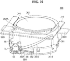
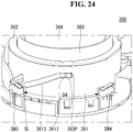
- the lifting unit 360 may include an outer housing 361, an inner housing 362, and a lifting housing 363.
- the outer housing 361, the inner housing 362, and / or the lifting housing 363 may have a cylindrical shape.
- the speaker 364 may be mounted in or fixed to the lifting housing 363.
- the speaker 364 may be located inside the lifting housing 363.
- the speaker 364 may move together with the lifting housing 363.
- the lifting housing 363 may have a protrusion 363P.
- the protrusion 363P may protrude from the outer surface of the lifting housing 363.
- a plurality of protrusions 363P may be formed.
- the lifting housing 363 may be mounted in or inserted into the inner housing 362.
- the lifting housing 363 may be located inside the inner housing 362.
- the inner housing 362 may have a guide slot 3621 formed to be long in the vertical direction.
- the guide slot 3621 may be vertically formed on one or both surfaces of the inner housing 362.
- the guide slot 3621 may have the shape of a slot.
- the protrude 363P of the lifting housing 363 may be inserted into the guide slot 3621 and may be moved up and down along the guide slot 3621.
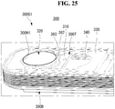
- the inner housing 362 may be mounted in or inserted into the outer housing 361.
- the inner housing 362 may be located inside the outer housing 361.
- Lift slot 3611, 3612, and 3613 may be formed on the outer housing 361.
- Lift slot 3611, 3612, and 3613 may extend from the left lower portion to the upper right portion of the outer housing 361.
- Lift slot 3611, 3612, and 3613 may extend from the right lower portion to the left upper portion of the outer housing 361.
- Lift slot 3611, 3612, and 3613 may have a shape of a groove formed on inner surface of the outer housing 361.
- Lift slot 3611, 3612, and 3613 may have a shape of a slot.
- the lift slot 3611, 3612, and 3613 may be formed to pass through the inner and outer surfaces of the outer housing 361.
- Lift slot 3611, 3612, and 3613 may be formed long in the diagonal direction of the outer housing 361.
- the lift slot 3611, 3612, and 3613 may include a first part 3611, a second part 3612, and a third part 3613.
- the first part 3611 may be formed at a lower portion of the outer housing 361.
- the first part 3611 may be formed horizontally.
- the second part 3612 may be formed on the upper portion of the outer housing 361.
- the second part 3612 may be formed horizontally.
- the second part 3612 may be spaced apart from the first part 3611 in the left-right direction.
- the third part 3613 may connect the first part 3611 and the second part 3612.
- the second part 3612 may be located with respect to the first part 3611 in an oblique direction.
- the outer housing 361 may include a sixth gear G6.
- the sixth gear G6 may be formed on the outer surface of the outer housing 361.
- the sixth gear G6 may be formed at the lower portion of the outer surface of the outer housing 361.
- the sixth gear G6 may be coupled with the outer housing 361.
- the torque limiter TL may be positioned near the fifth gear G5.
- the torque limiter TL may be positioned above the fifth gear G5.
- the torque limiter TL can be engaged with the upper surface of the fifth gear G5.
- the torque limiter TL may be mechanically connected to the fifth gear G5.
- the torque limiter TL may be a friction clutch.
- the driving unit M1 may be located outside the outer housing 361.
- the driving unit M1 may be fixed to the inner housing 362.
- the inner housing 362 may have a flange 362PL and the drive unit M may be mounted on or fixed to the flange 362PL.
- the driving unit M1 may be a motor.
- the driving unit M1 may be mechanically connected to the torque limiter TL and may provide rotational force to the torque limiter TL.
- the driving unit M1 may be referred to as a second driving unit.
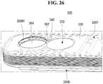
- the fifth gear G5 may rotate the outer housing 361.
- the inner housing 362 may not rotate.
- the lift slot 3611, 3612, 3613 may provide the protrusion 363P with a force.
- the protrusion 363P may be guided in up down direction by the guide slot 3621 (see FIG. 20 ). So, when the outer housing 361 rotates, the protrusion 363P moves upward and downward along the guide slot 3621.
- the lifting housing 363 may move up and down, and the speaker 364 may move up and down.
- the rotational force provided by the driving unit M1 fixed to the inner housing 362 may rotate the outer housing 361.
- the outer housing 361 may rotate relative to the inner housing 362.
- the lift slot 3611, 3612, 3613 can rotate with respect to the guide slots 3621 (see Fig. 20 ).
- the protrude 363P may move up and down in the guide slot 3621 (see Fig. 20 ).
- the first gear cover 365a may cover the sixth gear G6 of the outer housing 361.
- the second gear cover 365b may cover the fifth gear G5 and / or the torque limiter TL.
- the first gear cover 365a and the second gear cover 365b may be connected or coupled with each other.
- the first gear cover 365a and the second gear cover 365b may prevent the driving system of the lifting unit 360 from being contaminated by an external foreign material.
- the driving system may include a motor M1, a torque limiter TL, a fifth gear G5, and a sixth gear G6.
- the speaker 364 may be prevented from moving up and down by an external force despite the continuous rotation of the driving unit M1. At this time, the rotational force of the driving unit M1 may not be transmitted to the fifth gear G5 due to the slip caused by the torque limiter TL. In other words, the torque limiter TL may decouple the driving unit M1 from the fifth gear G5. Thus, the safety of the driving system of the lifting unit 360 can be secured.
- the switch SW3 and SW4 may be located outside the outer housing 361.
- the switch SW3 and SW4 may be plural.
- the third switch SW3 may be spaced a certain distance D4 from the fourth switch SW4.
- the certain distance D4 may be along the outer surface of the outer housing 361.
- the outer housing 361 may have a switching lever SL.
- the switching lever SL may protrude from the outer surface of the outer housing 361.
- the switching lever SL may operate the third switch SW3 or the fourth switch SW4.
- the switching lever SL may press the third switch SW3 or the fourth switch SW4 in accordance with the rotation of the outer housing 361.
- the third switch SW3 and / or the fourth switch SW4 may regulate the operation of the driver M1. Accordingly, the rotation range of the outer housing 361 may be limited, and the range of the vertical movement of the speaker 364 may also be constant.
- the cap 320 of the speaker module 300S1 may cover the opening 300H1 of the top case 300T. Accordingly, it is possible to protect the speaker module 300S1 and to prevent foreign matter from entering the sound system 300.
- the display panel 100 may not provide an image.
- the head 10 shown in Fig. 2
- the head 10 may be in a state in which power is not supplied to the head 10.
- the cap 320 may be slightly lowered from the opening 300H1 to the lower portion of the top case 300T. And then the cap 320 may move to the inside of the top case 300T as the slider 310 moves in left-right direction. And then the opening 300H1 of the top case 300T may be in an open state. Simultaneously, the display panel 100 (see FIG. 2 ) can provide an image. In other words, the head 10 (see FIG. 2 ) may be in a state of being supplied with electric power.
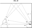
- the speaker 364 may ascend from the lower of the opening 300H1 to the upper of the opening 300H1. Accordingly, the speaker 364 may be exposed to the outside, and the sound generated from the speaker 364 can be transmitted to the outside without interference by the internal structure of the sound system 300. Simultaneously the display panel 100 (see FIG. 2 ) may provide an image. In other words, the head 10 (see FIG. 2 ) may be in a state of being supplied with electric power.
- the sound may be generated at the speaker 364 and reflected to the ceiling or the wall and transmitted to the viewer.
- the sound may be a middle tone or a high tone.
- the speakers 364 and 366 may be plural.
- the first speaker 366 may generate sound to the outside through the front surface of the sound system 300.
- the first speaker 366 may be a region of bass or treble.
- the second speaker 364 may be the speaker 364 described above.
- the sound system 300 may provide a various range of sound to the viewer. Although not shown, a separate woofer may be provided.
- the woofer may provide sound in the bass region.
Landscapes
- Engineering & Computer Science (AREA)
- Physics & Mathematics (AREA)
- Signal Processing (AREA)
- Acoustics & Sound (AREA)
- Theoretical Computer Science (AREA)
- General Physics & Mathematics (AREA)
- General Engineering & Computer Science (AREA)
- Multimedia (AREA)
- Health & Medical Sciences (AREA)
- Otolaryngology (AREA)
- Computer Hardware Design (AREA)
- Human Computer Interaction (AREA)
- Devices For Indicating Variable Information By Combining Individual Elements (AREA)
Description
- The present invention relates to a sound system. More particularly, the present invention relates to a sound system operatively associated with a display device.
- With the development of the information society, various demands for display devices have been increasing. Various display devices, such as, e.g., liquid crystal displays (LCDs), plasma display panels (PDPs), electroluminescent displays (ELDs), and vacuum fluorescent displays (VFDs), have been studied and used to meet various demands for the display devices.
- The OLED panel can display an image by depositing an organic layer capable of emitting light on a substrate on which a transparent electrode is formed. OLED panels are not only thin but also have flexible characteristics. Research has been conducted on the structural characteristics of a display device having such an OLED panel.
- In recent years, in order to realize various designs of display devices, a sound system or an image control system, which can be provided in a display device, tends to be separated from a display panel, and studies are actively conducted.
- Examples of prior art display panels are disclosed in
DE 197 37 058 C1 , the web page http://slideme.org/application/idisplay presenting an application called iDisplay (December 2012),US 2014/0341418 A1 ,US 2015/0340795 A1 ,US 2010/0296686 A1 ,US 4,884,646 A1 ,US 5,838,537 A andCN 105657302 A . - Accordingly, an object of the present disclosure is to address the above-described and other problems.
- Another object of the present disclosure is to provide a sound system movable in conjunction with driving of a display panel.
- The invention is defined by the appended claims. In the following, any embodiments not falling within the scope of the claims should be understood as examples and/or background information useful to understand the invention.
- The accompanying drawings, which are included to provide a further understanding of the invention and are incorporated in and constitute a part of this specification, illustrate embodiments of the invention and together with the description serve to explain the principles of the invention. In the drawings:
-
FIGS. 1 to 5 are views showing examples of display devices related to the present invention. -
FIGS. 6 and7 are views showing an example of a sound system and a display device having the same according to an embodiment of the present invention. -
FIG. 8 is a view showing an example of a sound system according to an embodiment of the present invention. -
FIGS. 9 to 17 are views showing examples of the automatic open / close structure of a sound system according to an embodiment of the present invention. -
FIGS. 18 to 27 are views showing examples of an automatic lifting structure of a sound system according to an embodiment of the present invention. -
FIG. 28 is a view showing an example of a sound system of a display device according to an embodiment of the present invention. - Reference will now be made in detail embodiments of the invention examples of which are illustrated in the accompanying drawings. Since the present invention may be modified in various ways and may have various forms, specific embodiments are illustrated in the drawings and are described in detail in the present specification. However, it should be understood that the present invention are not limited to specific disclosed embodiments, but include all modifications, equivalents and substitutes included within the technical scope of the present invention.
- The terms 'first', 'second', etc. may be used to describe various components, but the components are not limited by such terms. The terms are used only for the purpose of distinguishing one component from other components. For example, a first component may be designated as a second component without departing from the scope of the present invention. In the same manner, the second component may be designated as the first component.
- The term "and/or" encompasses both combinations of the plurality of related items disclosed and any item from among the plurality of related items disclosed.
- When an arbitrary component is described as "being connected to" or "being linked to" another component, this should be understood to mean that still another component(s) may exist between them, although the arbitrary component may be directly connected to, or linked to, the second component. In contrast, when an arbitrary component is described as "being directly connected to" or "being directly linked to" another component, this should be understood to mean that no component exists between them.
- The terms used in the present application are used to describe only specific embodiments or examples, and are not intended to limit the present invention. A singular expression can include a plural expression as long as it does not have an apparently different meaning in context.
- In the present application, the terms "include" and "have" should be understood to be intended to designate that illustrated features, numbers, steps, operations, components, parts or combinations thereof exist and not to preclude the existence of one or more different features, numbers, steps, operations, components, parts or combinations thereof, or the possibility of the addition thereof.
- Unless otherwise specified, all of the terms which are used herein, including the technical or scientific terms, have the same meanings as those that are generally understood by a person having ordinary knowledge in the art to which the present invention pertains. The terms defined in a generally used dictionary must be understood to have meanings identical to those used in the context of a related art, and are not to be construed to have ideal or excessively formal meanings unless they are obviously specified in the present application.
- The following exemplary embodiments of the present invention are provided to those skilled in the art in order to describe the present invention more completely. Accordingly, shapes and sizes of elements shown in the drawings may be exaggerated for clarity.
- Hereinafter, an organic light emitting diode (OLED) will be described as an example of the display panel. However, the display panel applicable to the present invention is not limited to the OLED panel. A plasma display panel (PDP), a field emission display (FED), and a liquid crystal display (LCD) are applicable to the present invention.
- Referring
FIG. 1 , the display device may include a first long side LS1 and a second long side LS2 opposite to a first long side LS1. The display device may include a first short side SS1 and a second short side SS2. The first short side SS1 may be adjacent to an end of the first long side LS1 and may be adjacent to an end of the second side LS2. The second short side SS2 may be opposite to the first short side SS1. - An area of the first short side SS1 may be referred to as a first side area and an area of the second short side SS2 may be referred to as a second side area opposite to the first side area. An area of the first
long side LS 1 may be referred to as a third side area. The third side area may be adjacent to the first side area and the second side area and located between the first side area and the second side area. An area of the second long side area LS2 may be referred to as a fourth side area. The fourth side area may be located between the first side area and the second side area and may be opposed to the third side area. - The lengths of the first and second
long sides LS 1 and LS2 may be longer than the lengths of the first and second short sides SS1 and SS2. The lengths of the first and second long sides LS1 and LS2 may be substantially the same as the lengths of the first and second short sides SS1 and SS2. - In the following description, a first direction DR1 may be a direction parallel to long sides LS1, LS2 of a display device, a second direction DR2 is a direction parallel to short sides SS1, SS2.
- The third direction DR3 may be a direction perpendicular to the first direction DR1 and / or the second direction DR2.
- The first direction DR1 and the second direction DR2 may collectively be referred to as a horizontal direction. In addition, the third direction DR3 may be referred to as a vertical direction.
- In another point of view, an orientation in which the
head 10 of the display device displays an image may be referred to as a forward or a front side. When thehead 10 of the display device displays an image, an orientation in which the image cannot be observed can be referred to as a rearward or a rear side. When looking at thehead 10 of the display from the forward or the front side, the first long side LS1 side may be referred to as a upward or a upper side. Likewise, the second long side LS2 can be referred to as a downward or a lower side. Similarly, the first short side SS1 may be referred to as a leftward or a left side, and the second short side SS2 may be referred to as a rightward or a right side. - The first long side LS1, the second long side LS2, the first short side SS1 and the second short side SS2 may be referred to as an edge of the
head 10 of the display device. The point where two sides among the first long side LS1, the second long side LS2, the first short side SS1, and the second short side SS2 meet with each other may be referred to as a corner. For example, a point where the first long side LS1 and the first short side SS1 meet may be the first corner C1, a point where the first long side LS1 and the second short side SS2 meet may be the second corner C2, a point where the second short side SS2 and the second long side LS2 meet may be a third corner C3, and a point where the second long side LS2 and the first short side SS1 meet may be a fourth corner C4.. - The direction from the first short side SS1 to the second short side SS2 or the direction from the second short side SS2 to the first short side SS1 can be referred to as the left and right direction LR. The direction from the first long side LS1 to the second long side LS2 or the direction from the second long side LS2 to the first long side LS1 may be the up and down direction UD.
- Referring to
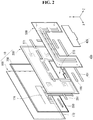
FIG. 2 , thehead 10 may include adisplay panel 100, aback cover 200, and aPCB cover 400. Thehead 10 may be referred to as adisplay unit 10. - The
display panel 100 may provided on the front side of thehead 10 and may display images. Thedisplay panel 100 may divide the image into a plurality of pixels and output an image according to the color, brightness, and saturation of each pixel. - The
display panel 100 may be an organic light emitting diode (OLED) panel. Thedisplay panel 100 may be a liquid crystal display (LCD) panel. - The
interface PCB 174 and the at least onesource PCB 172 may be located on at least a portion of the backside of thedisplay panel 100. Theinterface PCB 174 may be located above the at least onesource PCB 172. At least onesource PCB 172 may be coupled to theinterface PCB 174. Eachsource PCB 172 may be spaced apart from one another. The FFC 157 may be located between thesource PCB 172 and theinterface PCB 174. The FFC 157 can electrically connect thesource PCB 172 and theinterface PCB 174. - The
interface PCB 174 may be positioned with signal lines for transmitting digital video data and timing control signals transmitted from the timing controller board of the housing. - At least one
source PCB 172 may apply a voltage to thedisplay panel 100 in accordance with a signal transmitted from theinterface PCB 174. That is, at least onesource PCB 172 may apply a driving waveform to thedisplay panel 100 according to a video signal. Thesource PCB 172 may be connected to thedisplay panel 100 by a source COF (Chip On Film) 123. Thesource COF 123 connected to thesource PCB 172 may extend to the lower surface of thedisplay panel 100 and be connected to thedisplay panel 100. - The
source COF 123 may be electrically connected to thesource PCB 172 and the data pads of thedisplay panel 100. Thesource COF 123 can implement a data integrated circuit. - The
adhesive sheet 350 may be positioned on the rear surface of thedisplay panel 100 in order to couple thedisplay panel 100 and theback cover 200 together. Theadhesive sheet 350 may be in the form of a rectangular frame with an empty center. Since the center of theadhesive sheet 350 is empty, at least one PCB may be located in the empty space. - A surface of the
adhesive sheet 350 may be bonded to thedisplay panel 100. Another surface of theadhesive sheet 350 may be bonded to theback cover 200. - The insulating
sheet 251 may be located in correspondence with thesource PCB 172. The insulatingsheet 251 may be attached to the front surface of theback cover 200. The insulatingsheet 251 may include an insulating material such that thesource PCB 172 is not interfered with by other electronic devices. For example, thePCB cover 400 may comprise a plastic material. Accordingly, thePCB cover 400 can protect thesource PCB 172 from a leakage current. - The
back cover 200 may be positioned on the rear surface of thedisplay panel 100. Theback cover 200 may be attached to thedisplay panel 100 through theadhesive sheet 350. Theback cover 200 can support the rear surface of thedisplay panel 100. That is, theback cover 200 can reinforce the rigidity of thedisplay panel 100. Theback cover 200 may include a lightweight and high strength material. For example, theback cover 200 may comprise aluminum. - The
back cover 200 may have a different thickness depending on the position. Theback cover 200 may be formed. The thickness of the edge region of theback cover 200 may be greater than the thickness of the other portions of theback cover 200. Since theback cover 200 is formed, the rigidity of theback cover 200 can be improved. - The
coupling hole 271 may be positioned at a portion adjacent to the four corners of theback cover 200. Thecoupling hole 271 may be a portion penetrating theback cover 200. Thecoupling hole 271 can help to join thewall bracket 500 and thehead 10. The thickness in the vertical direction of the portion where thecoupling hole 271 is located may be greater than the thickness in the other direction. Accordingly, thewall bracket 500 and thehead 10 are adjacent to each other, so that the binding force can be strengthened. - The
coupling portion 166 can be positioned at the edge of theback cover 200. Thecoupling portion 166 may be located on at least one side of theback cover 200. Thecoupling portion 166 may protrude from theback cover 200 rearward. Accordingly, the portion where thecoupling portion 166 is located may be the same or similar in vertical height to the portion where thecoupling hole 271 of theback cover 200 is located. The position of thecoupling portion 166 is not limited and may be located at any portion of theback cover 200 if the thickness of the portion of theback cover 200 is thin. - The
coupling portion 166 may include a magnetic material. Thecoupling portion 166 may contribute to engaging of thehead 10 and thewall bracket 500 by using magnetism
Theback cover 200 may have anopening 273 at a portion corresponding to theinterface PCB 174 when theback cover 200 is coupled. For example, theopening 273 may be located at the center of theback cover 200. Theopening 273 can provide a space for theinterface PCB 174 to be positioned between thedisplay panel 100 and theback cover 200. If toomuch opening 273 is formed in theback cover 200, cracks may be formed in theback cover 200 or the rigidity may be weakened. Accordingly, it is preferable that theback cover 200 has asmall opening 273. - A
PCB cover 400 may be positioned at a rear of the PCB. ThePCB cover 400 may include first and second PCB covers 431 and 435. Thefirst PCB cover 431 may be positioned at a rear of thesource PCB 172 and thesecond PCB cover 435 may be positioned at a rear of theinterface PCB 174. That is, thesecond PCB cover 435 may cover theopening 273. ThePCB cover 400 may prevent thesource PCB 172 and theinterface PCB 174 from being exposed to the outside. Accordingly, thePCB cover 400 may be opaque so that thesource PCB 172 and theinterface PCB 174 are not invisible to the outside. - The
PCB cover 400 may include a material that is electrically insulative so that thesource PCB 172 and theinterface PCB 174 are not interfered with by other electronic devices. For example, thePCB cover 400 may comprise a plastic material. Accordingly, thePCB cover 400 can protect thesource PCB 172 and theinterface PCB 174 from leakage currents. - The
display panel 100 can be supported by only theback cover 200. That is, thehead 10 may not include the cover other than theback cover 200. Accordingly, the user can feel that the thickness of thehead 10 is very thin, and can concentrate more on the display screen. - Referring to
FIG. 3 , thedisplay panel 100 may include atransparent substrate 110, anupper electrode 120, an organiclight emitting layer 130, and alower electrode 140. Thetransparent substrate 110, theupper electrode 120, the organiclight emitting layer 130, and thelower electrode 140 may be sequentially formed. - The
transparent substrate 110 and theupper electrode 120 may include a transparent material. Thelower electrode 140 may include a non-transparent material. Thelower electrode 140 may include a transparent material (for example, ITO). In this case, light may be emitted to a surface of thelower electrode 140. - When a voltage is applied to the
upper electrode 120 andlower electrode 140, light emitted from the organiclight emitting layer 130 may be transmitted through theupper electrode 120 and thetransparent substrate 110 to be emitted to the outside. At this time, a light shielding plate may be further formed behind thelower electrode 140 to emit the light emitted to thelower electrode 140 to the front surface. - Referring to
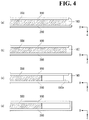
FIG. 4 , thedisplay panel 100 may be attached to theback cover 200 by anadhesive sheet 350. Theadhesive sheet 350 may include a double-sided tape. - The
adhesive sheet 350 may have a thickness. Accordingly, foreign substances or dust may enter between thedisplay panel 100 and theback cover 200. In order to prevent this, as shown inFig. 4 (a) , the sealingmember 183 can be side-sealed to at least a side of theadhesive sheet 350. The sealingmember 183 can shield at least one side of theadhesive sheet 350 and thedisplay panel 100 at the same time. - As another example, the
frame 187 may be inserted into at least one side of theadhesive sheet 350, as shown inFig. 4 (b) . Theframe 187 may contact at least one side of theadhesive sheet 350 and may be bent so that one end of theframe 187 extends toward thedisplay panel 100. Accordingly, at least one side of thedisplay panel 100 can be simultaneously shielded. - As another example, the
middle cabinet 193 may be positioned between thedisplay panel 100 and theback cover 200, as shown inFIG. 4 (c) . Themiddle cabinet 193 can guide the position where thedisplay panel 100 is coupled. Theflange 193a of themiddle cabinet 193 can be inserted between thedisplay panel 100 and theback cover 200. Themiddle cabinet 193 can shield at least one side of thedisplay panel 100 and theback cover 200 at the same time. - The
flange 193a of themiddle cabinet 193 may be spaced apart from theadhesive sheet 350. Accordingly, since theadhesive sheet 350 does not need to be entirely placed on thedisplay panel 100, the amount of theadhesive sheet 350 for the display device can be reduced. - As another example, the edge portion of the
back cover 200 may be bent toward thedisplay panel 100, as shown inFig. 4 (d) . Since the edge portion of theback cover 200 is bent, at least one side of theadhesive sheet 350 can be shielded from the outside. - In this case, other materials may not be included between the
display panel 100 and theback cover 200. Thus, the manufacturing process of the display device can be simplified, and the cost can be saved. Further, the edge of theback cover 200 can be separated from theadhesive sheet 350. Accordingly, since theadhesive sheet 350 does not need to be entirely placed on thedisplay panel 100, the amount of theadhesive sheet 350 for the display device can be reduced. - Referring to
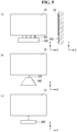
FIG. 5 , the display device may include ahousing 300 electrically connected to thehead 10. Thehousing 300 may include electrical unit providing thehead 10 or thedisplay unit 10, in particular the display panel 110 (shown inFIG. 2 ) with a signal and/or power. For instance, thehousing 300 electrically connected to thehead 10 or thedisplay unit 10 may mean the electrical unit electrically connected to the display panel 110(shown inFIG. 2 ) or thehead 10 or thedisplay unit 10. - The
housing 300 can transmit at least one signal to thehead 10. Thehousing 300 may shield the components that drive the display device. For example, thehousing 300 may shield at least one printed circuit board (PCB). The detailed coupling structure of the at least one printed circuit board and the method of coupling the at least one printed circuit board will be described later. - For example, as shown in
FIG. 5A , thehousing 300 may be connected to thehead unit 10 through a plurality offlat cables 161 having a flat shape. Theflat cable 161 may include a plurality of signal connection terminal pins and at least one ground terminal pin for connecting thehousing 300 and thehead unit 10. Theflat cable 161 is advantageous in cost compared to other cables. - As another example, as shown in
FIG. 5 (b) , thehousing 300 can be engaged with thehead 10 through onecircular cable 163. That is, a plurality offlat cables 161 inFIG. 3 (b) , can be connected through a singlecircular cable 163 inFIG. 5(b) . Since thehousing 300 and thehead unit 10 are connected through a singlecircular cable 163 rather than a plurality ofcircular cables 163, the user can feel that the appearance is cleaner. - As another example, as shown in
FIG. 5 (c) , thehousing 300 and thehead unit 10 can exchange electric signals wirelessly. In this case, the user may feel that the appearance is cleaner than when thehousing 300 and thehead part 10 are connected through theflat cable 161 or thecircular cable 163. - The
housing 300 may be described below as a sound system or control system or control unit. - Referring
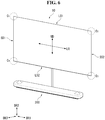
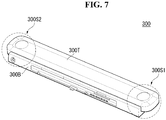
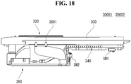
FIGS. 6 to 8 , thesound system 300 may be separated from thehead 10 by a certain distance. Thesound system 300 may be connected to thehead 10 electrically. Thesound system 300 may include a plurality of speaker modules 300S1 and 300S2. The plurality of speaker modules 300S1 and 300S2 may be installed inside thesound system 300. Thesound system 300 may include acase - The
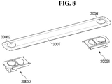
case bottom case 300B and atop case 300T. A part of the speaker modules 300S1 and 300S2 may be exposed to the outside at a part of thetop case 300T. Thetop case 300T may have openings 300H1 and 300H2. The openings 300H1 and 300H2 may be formed on one side or both sides of thetop case 300T. - The first speaker module 300S1 may be located on the left or right side of the
case case top case 300T and the second opening 300H2 may be formed on the right side or the left side of thetop case 300T. A part of the first speaker module 300S1 may be exposed to the outside of thetop case 300T through the first opening 300H1 and a part of the second speaker module 300S2 may be exposed to the outside of the top case 300T2 through the second opening 300H2. - Referring
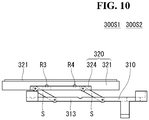
FIGS. 9 and10 , the speaker module 300S1, 300S2 may include aslider 310 and acap 320. Theslider 310 may have a plate shape. Theslider 310 may have asemicircular opening 311. Thesemicircular opening 311 may be referred to as anopening portion 311. Thecap 320 may include acircle 321 andbridge - The
circle 321 may have a smaller diameter than the diameter of theopening 311 of theslider 310. Thecircle 321 can be positioned in theopening 311 of theslider 310. Thebridges circle 321. Thebridges circle 321. Thebridges slider 310. The shape of thecircle 321 can be variously modified. - The
slider 310 may include afirst wing 312 and asecond wing 313. Thecap 320 may include afirst bridge 322 and asecond bridge 324. Thefirst bridge 322 may be mounted on thefirst wing 312 or fastened to thefirst wing 312. Thesecond bridge 324 may be mounted on thesecond wing 313 or fastened to thesecond wing 313. Thefirst bridge 322 and thesecond bridge 324 can move up and down from the upper part of thefirst wing 312 and thesecond wing 313. Thefirst bridge 322 and thesecond bridge 324 may be coupled to thefirst wing 312 and thesecond wing 313 by an elastic member S. The elastic member S may be, for example, a spring. - The
cap 320 may include rollers R1 to R4. The rollers R1 to R4 may be installed on thebridges first bridge 322 and the second roller R3, R4 may be located at thesecond bridge 324. The first roller R1, R2 and / or the second roller R3, R4 may be plural. The rollers R1 to R4 may be exposed above thebridges - Referring to
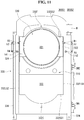
FIG. 11 , thebase cover 330 may have anopening 332, afirst side 334, and asecond side 336. Theopening 332 includes a first long side 332LS1, a second long side 332LS2, a first short side 332SS1, a second short side 332SS2, afirst bay 3321, and asecond bay 332F. Theopening 332 may be referred to as anopening portion 332. - The
opening 332 may have elongated shape as a whole. The first long side 332LS1 and / or the second long side 332LS2 may be straight. The first short side 332SS1 and / or the second short side 332SS2 may be straight or curved. - A
first bay 3321 may be formed on the first short side 332SS1. Thefirst bay 3321 may have a shape depressed into the inside of thebase cover 330. Thefirst bay 3321 may be adjacent to the first short side 332SS1. Asecond bay 332F may be formed on the second short side 332SS2. Thesecond bay 332F may have a shape depressed into the inside of thebase cover 330. Thesecond bay 332F may be adjacent to the second short side 332SS2. Asecond bay 332F may be formed on the second short side 332SS2. Thefirst bay 3321 may correspond to a side of thecap 320 or thecircle 321 and thesecond bay 332F may correspond to another side of thecap 320 or thecircle 321. - The
first side 334 may be located adjacent the first long side 332LS1 and thesecond side 336 may be located adjacent the second long side 332LS2. Thefirst side 334 and / or thesecond side 336 may be referred to as a rail. - The driving unit M may be installed adjacent to the
first side 334. For example, the driving unit M may be a motor. The driving unit M may be installed at an end of thefirst side 334 to provide rotational force. The driving unit M can be referred to as a first driving unit. - The rollers R1 to R4 may be positioned below the
first side 334 or thesecond side 336. The rollers R1 to R4 can move together with theslider 310 in the length direction of thefirst side 334 or thesecond side 336. Thefirst side 334 or thesecond side 336 may have holes h1 to h4 or grooves h1 to h4. The rollers R1 to R4 can be moved together with theslider 310 along thefirst side 334 or thesecond side 336 and then inserted into the holes h1 to h4 at a predetermined position. The holes are available to be referred to as grooves, and grooves are available to be referred to as holes. - At this time, the
cap 320 can be raised. Referring toFIG. 10 , the upward movement of thecap 320 may be performed at the moment when the roller R1 to R4 is inserted into the holes h1 to h4. - A plurality of holes h1 to h4 may be formed in the
first side 334 or thesecond side 336. The plurality of holes h1 to h4 may include first holes h1 and h3 and second holes h2 and h4. For example, the first holes h1 and h3 and the second holes h2 and h4 may be formed on thefirst side 336. The first holes h1 and h3 may not be arranged in line with the second holes h2 and h4. A line from the first hole h1 to the second hole h2 may form an inclination with respect to thefirst side 334. In other words, the second hole h2 may be beside of a trace of the first roller R1, and the first hole h1 may be beside of a trace of the second roller R2. A line from the first hole h3 to the second hole h4 may form an inclination with respect to thesecond side 336. In other words, the second hole h4 may be beside of a trace of the first roller R3, and the first hole h3 may be beside of a trace of the second roller R4. Above arrangement of the holes h1 to h4 may be referred to as a staggered arrangement. The first hole h1 may be left or right from the second hole h2 with respect to thefirst side 334. The first hole h3 may be left or right from the second hole h4 with respect to thesecond side 336. - The staggered arrangement of the first holes h1 and h3 and the second holes h2 and h4 may aims that the rollers R1 to R4 are inserted into the first holes h1 and h3 or the second holes h2 and h4. That is, one roller R can be inserted in one hole h at a predetermined position.
- Referring
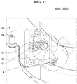
FIGS. 12 and13 , the motor M may be located at a side of thefirst side 334. The motor M may be mechanically connected to the first gear G1. And the second gear G2 may be engaged with the first gear G1. The second gear G2 may be installed on thefirst side 334. The second gear G2 can be fastened or fixed to the shaft SH. The shaft SH may be installed in thefirst side 334 or thebase cover 330 while passing through thefirst side 334 from the outside. - The third gear G3 may be located inside the
base cover 330 or inside thefirst side 334 and may be fastened or fixed to the shaft SH. The third gear G3 can rotate in the same manner as the rotation of the second gear G2. The fourth gear G4 can engage with the third gear G3. The fourth gear G4 can be fitted to thelead shaft 340. Thelead shaft 340 may rotate by the rotation of the fourth gear G4. Thelead shaft 340 may be referred to as a lead screw. - The first gear G1, the second gear G2, the third gear G3 and / or the fourth gear G4 may be referred to as gearbox.
- Referring to
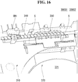
FIGS. 14 and15 , thelead shaft 340 may be provided withthread 342 on its outer circumferential surface. Thethread 342 may be referred to as ascrew thread 342. When the motor M provides rotational force to thelead shaft 340 through the gears G1 to G4, thelead screw shaft 340 rotates and thethread 342 can move theholder 350. Thethread 342 of thelead shaft 340 may be referred to as afirst thread 342. Thefirst thread 342 may have a shape that is recessed inward of thelead shaft 340, for example. - The
holder 350 may havethread 352. Thethread 352 of theholder 350 may be referred to as asecond thread 352. Theholder 350 may have a U- or V-shaped cross section as a whole and thesecond thread 352 may be formed on the inner surface of theholder 350. Thesecond thread 352 can be coupled with thefirst thread 342 of thelead shaft 340 when theholder 350 is fitted in thelead shaft 340. For example, thesecond thread 352 may be inserted into thefirst thread 342. The rotational motion of thelead shaft 340 can be converted into a linear motion of theholder 350. Thesecond thread 352 may be formed of a plurality of projections. - The
holder 350 may be fixed or fastened to theslider 310. Theholder 350 may move with theslider 310. When theholder 350 moves with respect to thelead shaft 340, theslider 310 may move with respect to thebase cover 330. - The
base cover 330 may include switches SW1 and SW2 under thefirst side 334. The first switch SW1 may be spaced a certain distance D1 from the second switch SW2. This distance D1 may correspond to the distance D2 that thecap 320 can move in theopening 332. - The
slider 310 may include aswitch contactor 310C. Theswitch contactor 310C may protrude from the lower side or lower surface of theslider 310. Theswitch contactor 310C may contact the first switch SW1 or the second switch SW2. When thecap 320 or theslider 310 moves with respect to thebase cover 330, theswitch contactor 310C may contact the first switch SW1 or the second switch SW2. - The first switch SW1 or the second switch SW2 may control the operation of the driving unit M.
- Referring to
FIGS. 16 and17 , theholder 350 may have elasticity. For example, theholder 350 may have a portion formed of a leaf spring. Theholder 350 can provide an elastic force in a direction perpendicular to the longitudinal direction of thelead shaft 340. Theholder 350 may be coupled or decoupled with thelead shaft 340. The number ofthreads 352 of theholder 350 may vary according to the elasticity of theholder 350. - The elastic force of the
holder 350 can be set to a constant intensity. The elastic force of theholder 350 may mean an elastic force per unit distance. If thecap 320 or theslider 310 is not moved by an external force while theholder 350 is moving on thelead shaft 340, thesecond thread 352 of theholder 350 is decoupled with thesecond thread 342 of thelead shaft 340. If thesecond thread 352 is derailed from thefirst thread 342, theholder 350 may not perform linear motion even if thelead screw 340 rotates. In case that the movement of thecap 320 or theslider 310 is abnormal, theholder 350 may provide the speaker module 300S1, 300S2 with safe structure. - Referring to
FIG. 18 , thelifting unit 360 may be coupled with thebase cover 330. Thelifting unit 360 may be mounted on the lower portion of thebase cover 330. Thelifting unit 360 may have afastening portion 3601. Thefastening portion 3601 may be fixed to thebase cover 330. - Referring to
FIGS. 19 and20 , thelifting unit 360 may include anouter housing 361, aninner housing 362, and a liftinghousing 363. Theouter housing 361, theinner housing 362, and / or the liftinghousing 363 may have a cylindrical shape. - The
speaker 364 may be mounted in or fixed to the liftinghousing 363. Thespeaker 364 may be located inside the liftinghousing 363. Thespeaker 364 may move together with the liftinghousing 363. The liftinghousing 363 may have aprotrusion 363P. Theprotrusion 363P may protrude from the outer surface of the liftinghousing 363. A plurality ofprotrusions 363P may be formed. - The lifting
housing 363 may be mounted in or inserted into theinner housing 362. The liftinghousing 363 may be located inside theinner housing 362. Theinner housing 362 may have aguide slot 3621 formed to be long in the vertical direction. Theguide slot 3621 may be vertically formed on one or both surfaces of theinner housing 362. Theguide slot 3621 may have the shape of a slot. Theprotrude 363P of the liftinghousing 363 may be inserted into theguide slot 3621 and may be moved up and down along theguide slot 3621. - The
inner housing 362 may be mounted in or inserted into theouter housing 361. Theinner housing 362 may be located inside theouter housing 361.Lift slot outer housing 361.Lift slot outer housing 361.Lift slot outer housing 361.Lift slot outer housing 361.Lift slot lift slot outer housing 361.Lift slot outer housing 361. - The
lift slot first part 3611, asecond part 3612, and athird part 3613. Thefirst part 3611 may be formed at a lower portion of theouter housing 361. Thefirst part 3611 may be formed horizontally. Thesecond part 3612 may be formed on the upper portion of theouter housing 361. Thesecond part 3612 may be formed horizontally. Thesecond part 3612 may be spaced apart from thefirst part 3611 in the left-right direction. Thethird part 3613 may connect thefirst part 3611 and thesecond part 3612. Thesecond part 3612 may be located with respect to thefirst part 3611 in an oblique direction. - Referring to
FIGS. 21 and22 , theouter housing 361 may include a sixth gear G6. The sixth gear G6 may be formed on the outer surface of theouter housing 361. The sixth gear G6 may be formed at the lower portion of the outer surface of theouter housing 361. The sixth gear G6 may be coupled with theouter housing 361. - And the fifth gear G5 can be engaged with the sixth gear G6. The torque limiter TL may be positioned near the fifth gear G5. For example, the torque limiter TL may be positioned above the fifth gear G5. For example, the torque limiter TL can be engaged with the upper surface of the fifth gear G5. The torque limiter TL may be mechanically connected to the fifth gear G5. For example, the torque limiter TL may be a friction clutch.
- The driving unit M1 may be located outside the
outer housing 361. The driving unit M1 may be fixed to theinner housing 362. Theinner housing 362 may have a flange 362PL and the drive unit M may be mounted on or fixed to the flange 362PL. For example, the driving unit M1 may be a motor. - The driving unit M1 may be mechanically connected to the torque limiter TL and may provide rotational force to the torque limiter TL. The driving unit M1 may be referred to as a second driving unit.
- Referring to
FIGS. 22 and23 , when the driving unit M1 provides rotational force to the fifth gear G5, the fifth gear G5 may rotate theouter housing 361. When theouter housing 361 rotates, theinner housing 362 may not rotate. When theouter housing 361 rotates, thelift slot protrusion 363P with a force. Theprotrusion 363P may be guided in up down direction by the guide slot 3621 (seeFIG. 20 ). So, when theouter housing 361 rotates, theprotrusion 363P moves upward and downward along theguide slot 3621. - When the
protrusion 363P moves along theguide slot 3621, the liftinghousing 363 may move up and down, and thespeaker 364 may move up and down. - The rotational force provided by the driving unit M1 fixed to the
inner housing 362 may rotate theouter housing 361. Theouter housing 361 may rotate relative to theinner housing 362. Thelift slot Fig. 20 ). Theprotrude 363P may move up and down in the guide slot 3621 (seeFig. 20 ). - The
first gear cover 365a may cover the sixth gear G6 of theouter housing 361. Thesecond gear cover 365b may cover the fifth gear G5 and / or the torque limiter TL. Thefirst gear cover 365a and thesecond gear cover 365b may be connected or coupled with each other. Thefirst gear cover 365a and thesecond gear cover 365b may prevent the driving system of thelifting unit 360 from being contaminated by an external foreign material. The driving system may include a motor M1, a torque limiter TL, a fifth gear G5, and a sixth gear G6. - The
speaker 364 may be prevented from moving up and down by an external force despite the continuous rotation of the driving unit M1. At this time, the rotational force of the driving unit M1 may not be transmitted to the fifth gear G5 due to the slip caused by the torque limiter TL. In other words, the torque limiter TL may decouple the driving unit M1 from the fifth gear G5. Thus, the safety of the driving system of thelifting unit 360 can be secured. - Referring to
FIG. 24 , the switch SW3 and SW4 may be located outside theouter housing 361. The switch SW3 and SW4 may be plural. The third switch SW3 may be spaced a certain distance D4 from the fourth switch SW4. The certain distance D4 may be along the outer surface of theouter housing 361. Theouter housing 361 may have a switching lever SL. The switching lever SL may protrude from the outer surface of theouter housing 361. The switching lever SL may operate the third switch SW3 or the fourth switch SW4. For instance, the switching lever SL may press the third switch SW3 or the fourth switch SW4 in accordance with the rotation of theouter housing 361. The third switch SW3 and / or the fourth switch SW4 may regulate the operation of the driver M1. Accordingly, the rotation range of theouter housing 361 may be limited, and the range of the vertical movement of thespeaker 364 may also be constant. - Referring to
FIG. 25 , thecap 320 of the speaker module 300S1 may cover the opening 300H1 of thetop case 300T. Accordingly, it is possible to protect the speaker module 300S1 and to prevent foreign matter from entering thesound system 300. At this time, the display panel 100 (seeFIG. 2 ) may not provide an image. In other words, the head 10 (shown inFig. 2 ) may be in a state in which power is not supplied to thehead 10. - Referring to
FIG. 26 , thecap 320 may be slightly lowered from the opening 300H1 to the lower portion of thetop case 300T. And then thecap 320 may move to the inside of thetop case 300T as theslider 310 moves in left-right direction. And then the opening 300H1 of thetop case 300T may be in an open state. Simultaneously, the display panel 100 (seeFIG. 2 ) can provide an image. In other words, the head 10 (seeFIG. 2 ) may be in a state of being supplied with electric power. - Referring to
FIG. 27 , thespeaker 364 may ascend from the lower of the opening 300H1 to the upper of the opening 300H1. Accordingly, thespeaker 364 may be exposed to the outside, and the sound generated from thespeaker 364 can be transmitted to the outside without interference by the internal structure of thesound system 300. Simultaneously the display panel 100 (seeFIG. 2 ) may provide an image. In other words, the head 10 (seeFIG. 2 ) may be in a state of being supplied with electric power. - Referring to
FIG. 28 , the sound may be generated at thespeaker 364 and reflected to the ceiling or the wall and transmitted to the viewer. For example, the sound may be a middle tone or a high tone. Thespeakers first speaker 366 may generate sound to the outside through the front surface of thesound system 300. For example, thefirst speaker 366 may be a region of bass or treble. Thesecond speaker 364 may be thespeaker 364 described above. Thesound system 300 may provide a various range of sound to the viewer. Although not shown, a separate woofer may be provided. The woofer may provide sound in the bass region. - The foregoing embodiments are merely examples and are not to be considered as limiting the present disclosure. The present teachings can be readily applied to other types of methods and apparatuses. The features, structures, methods, and other characteristics of the embodiments described herein may be combined in various ways to obtain additional and/or alternative embodiments, provided that they fall within the scope of the claims.
- Certain embodiments or other embodiments of the invention described above are not mutually exclusive or distinct from each other. Any or all elements of the embodiments of the invention described above may be combined or combined with each other in configuration or function.
- Although embodiments have been described with reference to a number of illustrative embodiments thereof, it should be understood that numerous other modifications and embodiments can be devised by those skilled in the art that will fall within the scope of the claims. More particularly, various variations and modifications are possible in the component parts and/or arrangements of the subject combination arrangement within the scope of the appended claims. In addition to variations and modifications in the component parts and/or arrangements, alternative uses will also be apparent to those skilled in the art.
Claims (14)
- A display device comprising:a display unit (10) including a display panel (110) providing an image;a housing (300) being apart from the display unit (10) and including an electrical unit; anda cable (161, 163) electrically connected with the display panel (110) and the electrical unit,wherein the electrical unit provides the display panel with a signal and power, andwherein the housing (300) comprises:a bottom case (300B);a top case (300T) above the bottom case (300B), the top case (300T) including an opening (300H1, 300H2);a speaker (364) moving in a vertical direction, the speaker (364) exposed to the outside of the top case (300T) through the opening (300H1, 300H2) or positioned between the top case (300T) and the bottom case (300B) according to a movement in the vertical direction,a slider (310) between the top case (300T) and the speaker (364), the slider (310) moving linearly;a cap (320) mounted on the slider (310), wherein the cap (320) open and close the opening (300H1, 300H2) of the top case (300T);a lead screw (340) near the slider (310), the lead screw (340) rotatable; anda holder (350) fixed to the slider (310), the holder (350) coupled with the lead screw (340), wherein the holder (350) moves along an axis of the lead screw (340) in accordance with a rotation of the lead screw (340).
- The display device of claim 1, wherein the power and the signal are transmitted by the cable (161, 163).
- The display device of claim 1, wherein the housing (300) further comprises a speaker module (300S1, 300S2), the speaker module (300S1, 300S2) includes the speaker (364)
- The display device of claim 3, wherein the speaker (364) is adapted to move to an upper position such that at least a part of the speaker (364) is located outside of the housing (300).
- The display device of claim 3, wherein the speaker (364) produces a sound in accordance with the image displayed by the display panel (110).
- The display device of claim 1, wherein the cap (320) open the opening (300H1, 300H2) of the top case (300T) when the display panel (110) is provided with an electrical power, and wherein the cap (320) close the opening (300H1, 300H2) of the top case (300T) when the electrical power to the display panel (110) is cut off.
- The display device of claim 1, wherein the lead screw (340) includes a screw thread (342), and wherein the holder (350) includes a plurality of protrusions (352) fitted in the screw thread (342) of the lead screw (340).
- The display device of claim 1, wherein the holder (350) has elasticity.
- The display device of claim 1, wherein the holder (350) is in contact with the lead screw (340) at left side and right side of the lead screw (340) with respect to an axis of the lead screw (340).
- The display device of claim 1, further comprising a driving unit (M) connected to the lead screw (340) mechanically, wherein the driving unit (M) provides the lead screw (340) with a rotational force.
- The display device of claim 10, further comprising a gearbox positioned between the driving unit (M) and the lead screw (340), wherein a portion of the gearbox is connected to the lead screw (340) and another portion of the gearbox is connected to the driving unit (M).
- The display device of claim 1, further comprising:a first switch (SW1);a second switch (SW2) spaced apart from the first switch (SW1); anda switch contactor (310C) formed at the slider (310), wherein the switch contactor (310C) contacts the first switch (SW1) or the second switch (SW2) in accordance with a movement of the slider (310).
- The display device of claim 12, further comprising a driving unit (M), wherein the driving unit (M) provides the lead screw (340) with a rotational force, and wherein the first and second switches (SW1, SW2) regulate a driving force supplied to the driving unit (M).
- The display device of claim 1, further comprising an elastic member (S), wherein a side of the elastic member (S) is fixed to the slider (310) and another side of the elastic member (S) is fixed to the cap (320), wherein the slider (310) includes an opening portion (332), wherein the cap (320) is positioned in the opening portion (332), and the cap (320) is provided with an elastic force upward of the slider (310).
Applications Claiming Priority (2)
| Application Number | Priority Date | Filing Date | Title |
|---|---|---|---|
| US201662366103P | 2016-07-24 | 2016-07-24 | |
| KR1020160107576A KR102513194B1 (en) | 2016-08-24 | 2016-08-24 | Sound system and display device comprising it |
Publications (2)
| Publication Number | Publication Date |
|---|---|
| EP3276978A1 EP3276978A1 (en) | 2018-01-31 |
| EP3276978B1 true EP3276978B1 (en) | 2020-09-02 |
Family
ID=59631523
Family Applications (1)
| Application Number | Title | Priority Date | Filing Date |
|---|---|---|---|
| EP17180150.9A Active EP3276978B1 (en) | 2016-07-24 | 2017-07-06 | Sound system and display device comprising it |
Country Status (4)
| Country | Link |
|---|---|
| US (1) | US10095264B2 (en) |
| EP (1) | EP3276978B1 (en) |
| KR (1) | KR102513194B1 (en) |
| CN (2) | CN107657933B (en) |
Families Citing this family (6)
| Publication number | Priority date | Publication date | Assignee | Title |
|---|---|---|---|---|
| KR102513194B1 (en) * | 2016-08-24 | 2023-03-24 | 엘지전자 주식회사 | Sound system and display device comprising it |
| KR102455299B1 (en) * | 2018-03-07 | 2022-10-17 | 엘지전자 주식회사 | Display device |
| CN109889745B (en) * | 2019-03-19 | 2020-11-06 | 深圳市万普拉斯科技有限公司 | Sound box structure and display device |
| KR102693630B1 (en) * | 2019-07-04 | 2024-08-08 | 엘지디스플레이 주식회사 | Display apparatus |
| KR20220106814A (en) * | 2019-12-27 | 2022-07-29 | 엘지전자 주식회사 | display device |
| CN112904940B (en) * | 2021-02-05 | 2022-07-26 | 青岛文达通科技股份有限公司 | Community's wisdom endowment service device |
Citations (1)
| Publication number | Priority date | Publication date | Assignee | Title |
|---|---|---|---|---|
| US5838537A (en) * | 1996-08-21 | 1998-11-17 | Gateway 2000, Inc. | Retractable speakers for portable computer |
Family Cites Families (16)
| Publication number | Priority date | Publication date | Assignee | Title |
|---|---|---|---|---|
| US4884646A (en) | 1988-07-18 | 1989-12-05 | Zambias Robert A | Anti-theft device for automobile audio equipment |
| DE19737058C1 (en) | 1997-08-26 | 1999-04-01 | Loewe Opta Gmbh | Visual display unit with flat display and loudspeaker arrangement |
| JP2007037092A (en) * | 2005-06-24 | 2007-02-08 | Sony Corp | Audio/display apparatus |
| JP2007006280A (en) * | 2005-06-24 | 2007-01-11 | Sony Corp | Multichannel sound reproduction system |
| KR20080019320A (en) * | 2006-08-28 | 2008-03-04 | 삼성전자주식회사 | Bar type portable terminal |
| CN101661308A (en) * | 2008-08-25 | 2010-03-03 | 和硕联合科技股份有限公司 | Portable electronic device |
| US8072748B2 (en) * | 2008-08-25 | 2011-12-06 | Pegatron Corporation | Portable electronic device |
| KR20100123009A (en) * | 2009-05-14 | 2010-11-24 | 엘지전자 주식회사 | Display apparatus |
| JP5249128B2 (en) | 2009-05-22 | 2013-07-31 | キヤノン株式会社 | Speaker device |
| KR20120059308A (en) * | 2010-11-30 | 2012-06-08 | 현대자동차주식회사 | Pop-up tweeter speaker |
| WO2014101033A1 (en) * | 2012-12-27 | 2014-07-03 | Intel Corporation | Electronic device having expandable speaker box |
| US9331417B2 (en) * | 2014-05-20 | 2016-05-03 | Apple Inc. | Electronic devices with housing port shutters |
| CN105491313A (en) * | 2014-09-15 | 2016-04-13 | 鸿富锦精密工业(深圳)有限公司 | Display device and mechanism structure |
| KR102484981B1 (en) | 2015-11-24 | 2023-01-05 | 엘지전자 주식회사 | Speaker module, electronic device and display device comprising it |
| CN105657302B (en) | 2016-01-21 | 2018-05-18 | 深圳创维-Rgb电子有限公司 | A kind of driving mechanism of slide cover and its laser television |
| KR102513194B1 (en) * | 2016-08-24 | 2023-03-24 | 엘지전자 주식회사 | Sound system and display device comprising it |
-
2016
- 2016-08-24 KR KR1020160107576A patent/KR102513194B1/en active IP Right Grant
-
2017
- 2017-06-13 US US15/621,064 patent/US10095264B2/en active Active
- 2017-07-03 CN CN201710532060.1A patent/CN107657933B/en active Active
- 2017-07-03 CN CN201720795764.3U patent/CN207149237U/en active Active
- 2017-07-06 EP EP17180150.9A patent/EP3276978B1/en active Active
Patent Citations (1)
| Publication number | Priority date | Publication date | Assignee | Title |
|---|---|---|---|---|
| US5838537A (en) * | 1996-08-21 | 1998-11-17 | Gateway 2000, Inc. | Retractable speakers for portable computer |
Also Published As
| Publication number | Publication date |
|---|---|
| CN107657933B (en) | 2020-08-28 |
| US20180024588A1 (en) | 2018-01-25 |
| CN107657933A (en) | 2018-02-02 |
| US10095264B2 (en) | 2018-10-09 |
| CN207149237U (en) | 2018-03-27 |
| KR102513194B1 (en) | 2023-03-24 |
| EP3276978A1 (en) | 2018-01-31 |
| KR20180022309A (en) | 2018-03-06 |
Similar Documents
| Publication | Publication Date | Title |
|---|---|---|
| EP3276978B1 (en) | Sound system and display device comprising it | |
| EP3772875A1 (en) | Printed circuit board mounting structure and display apparatus including the same | |
| KR102484981B1 (en) | Speaker module, electronic device and display device comprising it | |
| EP3333623B1 (en) | Display device | |
| KR20060064026A (en) | Flat type image display device | |
| KR102560611B1 (en) | Display device | |
| US9826296B2 (en) | Speaker assembly and display device including speaker assembly | |
| US9888595B2 (en) | Display device | |
| EP3157020B1 (en) | Display device | |
| CN107437379B (en) | Display device | |
| US9877402B2 (en) | Display device | |
| KR102513172B1 (en) | Sound system and display device comprising it | |
| US11714305B2 (en) | Display apparatus | |
| KR20170062937A (en) | Display apparatus | |
| KR102665993B1 (en) | Display device | |
| KR20210051076A (en) | Display device | |
| US20240164037A1 (en) | Display device | |
| KR102502075B1 (en) | Display apparatus | |
| KR102489004B1 (en) | Display device | |
| US10194539B2 (en) | Display device | |
| KR102687918B1 (en) | Display device | |
| KR20170084470A (en) | Display apparatus | |
| KR102423525B1 (en) | Display apparatus | |
| KR20170006011A (en) | Display apparatus |
Legal Events
| Date | Code | Title | Description |
|---|---|---|---|
| PUAI | Public reference made under article 153(3) epc to a published international application that has entered the european phase |
Free format text: ORIGINAL CODE: 0009012 |
|
| STAA | Information on the status of an ep patent application or granted ep patent |
Free format text: STATUS: REQUEST FOR EXAMINATION WAS MADE |
|
| 17P | Request for examination filed |
Effective date: 20170706 |
|
| AK | Designated contracting states |
Kind code of ref document: A1 Designated state(s): AL AT BE BG CH CY CZ DE DK EE ES FI FR GB GR HR HU IE IS IT LI LT LU LV MC MK MT NL NO PL PT RO RS SE SI SK SM TR |
|
| AX | Request for extension of the european patent |
Extension state: BA ME |
|
| RBV | Designated contracting states (corrected) |
Designated state(s): AL AT BE BG CH CY CZ DE DK EE ES FI FR GB GR HR HU IE IS IT LI LT LU LV MC MK MT NL NO PL PT RO RS SE SI SK SM TR |
|
| STAA | Information on the status of an ep patent application or granted ep patent |
Free format text: STATUS: EXAMINATION IS IN PROGRESS |
|
| 17Q | First examination report despatched |
Effective date: 20190521 |
|
| GRAP | Despatch of communication of intention to grant a patent |
Free format text: ORIGINAL CODE: EPIDOSNIGR1 |
|
| STAA | Information on the status of an ep patent application or granted ep patent |
Free format text: STATUS: GRANT OF PATENT IS INTENDED |
|
| RIC1 | Information provided on ipc code assigned before grant |
Ipc: H04R 5/02 20060101ALN20200121BHEP Ipc: H04N 5/64 20060101ALN20200121BHEP Ipc: H04R 1/02 20060101AFI20200121BHEP |
|
| INTG | Intention to grant announced |
Effective date: 20200212 |
|
| GRAS | Grant fee paid |
Free format text: ORIGINAL CODE: EPIDOSNIGR3 |
|
| GRAA | (expected) grant |
Free format text: ORIGINAL CODE: 0009210 |
|
| STAA | Information on the status of an ep patent application or granted ep patent |
Free format text: STATUS: THE PATENT HAS BEEN GRANTED |
|
| AK | Designated contracting states |
Kind code of ref document: B1 Designated state(s): AL AT BE BG CH CY CZ DE DK EE ES FI FR GB GR HR HU IE IS IT LI LT LU LV MC MK MT NL NO PL PT RO RS SE SI SK SM TR |
|
| REG | Reference to a national code |
Ref country code: GB Ref legal event code: FG4D |
|
| REG | Reference to a national code |
Ref country code: AT Ref legal event code: REF Ref document number: 1310206 Country of ref document: AT Kind code of ref document: T Effective date: 20200915 Ref country code: CH Ref legal event code: EP |
|
| REG | Reference to a national code |
Ref country code: DE Ref legal event code: R096 Ref document number: 602017022648 Country of ref document: DE |
|
| REG | Reference to a national code |
Ref country code: IE Ref legal event code: FG4D |
|
| REG | Reference to a national code |
Ref country code: LT Ref legal event code: MG4D |
|
| PG25 | Lapsed in a contracting state [announced via postgrant information from national office to epo] |
Ref country code: FI Free format text: LAPSE BECAUSE OF FAILURE TO SUBMIT A TRANSLATION OF THE DESCRIPTION OR TO PAY THE FEE WITHIN THE PRESCRIBED TIME-LIMIT Effective date: 20200902 Ref country code: NO Free format text: LAPSE BECAUSE OF FAILURE TO SUBMIT A TRANSLATION OF THE DESCRIPTION OR TO PAY THE FEE WITHIN THE PRESCRIBED TIME-LIMIT Effective date: 20201202 Ref country code: GR Free format text: LAPSE BECAUSE OF FAILURE TO SUBMIT A TRANSLATION OF THE DESCRIPTION OR TO PAY THE FEE WITHIN THE PRESCRIBED TIME-LIMIT Effective date: 20201203 Ref country code: BG Free format text: LAPSE BECAUSE OF FAILURE TO SUBMIT A TRANSLATION OF THE DESCRIPTION OR TO PAY THE FEE WITHIN THE PRESCRIBED TIME-LIMIT Effective date: 20201202 Ref country code: SE Free format text: LAPSE BECAUSE OF FAILURE TO SUBMIT A TRANSLATION OF THE DESCRIPTION OR TO PAY THE FEE WITHIN THE PRESCRIBED TIME-LIMIT Effective date: 20200902 Ref country code: HR Free format text: LAPSE BECAUSE OF FAILURE TO SUBMIT A TRANSLATION OF THE DESCRIPTION OR TO PAY THE FEE WITHIN THE PRESCRIBED TIME-LIMIT Effective date: 20200902 Ref country code: LT Free format text: LAPSE BECAUSE OF FAILURE TO SUBMIT A TRANSLATION OF THE DESCRIPTION OR TO PAY THE FEE WITHIN THE PRESCRIBED TIME-LIMIT Effective date: 20200902 |
|
| REG | Reference to a national code |
Ref country code: NL Ref legal event code: MP Effective date: 20200902 |
|
| REG | Reference to a national code |
Ref country code: AT Ref legal event code: MK05 Ref document number: 1310206 Country of ref document: AT Kind code of ref document: T Effective date: 20200902 |
|
| PG25 | Lapsed in a contracting state [announced via postgrant information from national office to epo] |
Ref country code: RS Free format text: LAPSE BECAUSE OF FAILURE TO SUBMIT A TRANSLATION OF THE DESCRIPTION OR TO PAY THE FEE WITHIN THE PRESCRIBED TIME-LIMIT Effective date: 20200902 Ref country code: LV Free format text: LAPSE BECAUSE OF FAILURE TO SUBMIT A TRANSLATION OF THE DESCRIPTION OR TO PAY THE FEE WITHIN THE PRESCRIBED TIME-LIMIT Effective date: 20200902 Ref country code: PL Free format text: LAPSE BECAUSE OF FAILURE TO SUBMIT A TRANSLATION OF THE DESCRIPTION OR TO PAY THE FEE WITHIN THE PRESCRIBED TIME-LIMIT Effective date: 20200902 |
|
| PG25 | Lapsed in a contracting state [announced via postgrant information from national office to epo] |
Ref country code: SM Free format text: LAPSE BECAUSE OF FAILURE TO SUBMIT A TRANSLATION OF THE DESCRIPTION OR TO PAY THE FEE WITHIN THE PRESCRIBED TIME-LIMIT Effective date: 20200902 Ref country code: EE Free format text: LAPSE BECAUSE OF FAILURE TO SUBMIT A TRANSLATION OF THE DESCRIPTION OR TO PAY THE FEE WITHIN THE PRESCRIBED TIME-LIMIT Effective date: 20200902 Ref country code: RO Free format text: LAPSE BECAUSE OF FAILURE TO SUBMIT A TRANSLATION OF THE DESCRIPTION OR TO PAY THE FEE WITHIN THE PRESCRIBED TIME-LIMIT Effective date: 20200902 Ref country code: PT Free format text: LAPSE BECAUSE OF FAILURE TO SUBMIT A TRANSLATION OF THE DESCRIPTION OR TO PAY THE FEE WITHIN THE PRESCRIBED TIME-LIMIT Effective date: 20210104 Ref country code: CZ Free format text: LAPSE BECAUSE OF FAILURE TO SUBMIT A TRANSLATION OF THE DESCRIPTION OR TO PAY THE FEE WITHIN THE PRESCRIBED TIME-LIMIT Effective date: 20200902 |
|
| PG25 | Lapsed in a contracting state [announced via postgrant information from national office to epo] |
Ref country code: IS Free format text: LAPSE BECAUSE OF FAILURE TO SUBMIT A TRANSLATION OF THE DESCRIPTION OR TO PAY THE FEE WITHIN THE PRESCRIBED TIME-LIMIT Effective date: 20210102 Ref country code: ES Free format text: LAPSE BECAUSE OF FAILURE TO SUBMIT A TRANSLATION OF THE DESCRIPTION OR TO PAY THE FEE WITHIN THE PRESCRIBED TIME-LIMIT Effective date: 20200902 Ref country code: AL Free format text: LAPSE BECAUSE OF FAILURE TO SUBMIT A TRANSLATION OF THE DESCRIPTION OR TO PAY THE FEE WITHIN THE PRESCRIBED TIME-LIMIT Effective date: 20200902 Ref country code: AT Free format text: LAPSE BECAUSE OF FAILURE TO SUBMIT A TRANSLATION OF THE DESCRIPTION OR TO PAY THE FEE WITHIN THE PRESCRIBED TIME-LIMIT Effective date: 20200902 |
|
| REG | Reference to a national code |
Ref country code: DE Ref legal event code: R097 Ref document number: 602017022648 Country of ref document: DE |
|
| PG25 | Lapsed in a contracting state [announced via postgrant information from national office to epo] |
Ref country code: SK Free format text: LAPSE BECAUSE OF FAILURE TO SUBMIT A TRANSLATION OF THE DESCRIPTION OR TO PAY THE FEE WITHIN THE PRESCRIBED TIME-LIMIT Effective date: 20200902 |
|
| PLBE | No opposition filed within time limit |
Free format text: ORIGINAL CODE: 0009261 |
|
| STAA | Information on the status of an ep patent application or granted ep patent |
Free format text: STATUS: NO OPPOSITION FILED WITHIN TIME LIMIT |
|
| 26N | No opposition filed |
Effective date: 20210603 |
|
| PG25 | Lapsed in a contracting state [announced via postgrant information from national office to epo] |
Ref country code: SI Free format text: LAPSE BECAUSE OF FAILURE TO SUBMIT A TRANSLATION OF THE DESCRIPTION OR TO PAY THE FEE WITHIN THE PRESCRIBED TIME-LIMIT Effective date: 20200902 Ref country code: DK Free format text: LAPSE BECAUSE OF FAILURE TO SUBMIT A TRANSLATION OF THE DESCRIPTION OR TO PAY THE FEE WITHIN THE PRESCRIBED TIME-LIMIT Effective date: 20200902 |
|
| PG25 | Lapsed in a contracting state [announced via postgrant information from national office to epo] |
Ref country code: IT Free format text: LAPSE BECAUSE OF FAILURE TO SUBMIT A TRANSLATION OF THE DESCRIPTION OR TO PAY THE FEE WITHIN THE PRESCRIBED TIME-LIMIT Effective date: 20200902 |
|
| REG | Reference to a national code |
Ref country code: CH Ref legal event code: PL |
|
| PG25 | Lapsed in a contracting state [announced via postgrant information from national office to epo] |
Ref country code: MC Free format text: LAPSE BECAUSE OF FAILURE TO SUBMIT A TRANSLATION OF THE DESCRIPTION OR TO PAY THE FEE WITHIN THE PRESCRIBED TIME-LIMIT Effective date: 20200902 |
|
| REG | Reference to a national code |
Ref country code: BE Ref legal event code: MM Effective date: 20210731 |
|
| PG25 | Lapsed in a contracting state [announced via postgrant information from national office to epo] |
Ref country code: LI Free format text: LAPSE BECAUSE OF NON-PAYMENT OF DUE FEES Effective date: 20210731 Ref country code: CH Free format text: LAPSE BECAUSE OF NON-PAYMENT OF DUE FEES Effective date: 20210731 |
|
| PG25 | Lapsed in a contracting state [announced via postgrant information from national office to epo] |
Ref country code: LU Free format text: LAPSE BECAUSE OF NON-PAYMENT OF DUE FEES Effective date: 20210706 |
|
| PG25 | Lapsed in a contracting state [announced via postgrant information from national office to epo] |
Ref country code: IE Free format text: LAPSE BECAUSE OF NON-PAYMENT OF DUE FEES Effective date: 20210706 Ref country code: BE Free format text: LAPSE BECAUSE OF NON-PAYMENT OF DUE FEES Effective date: 20210731 |
|
| PG25 | Lapsed in a contracting state [announced via postgrant information from national office to epo] |
Ref country code: HU Free format text: LAPSE BECAUSE OF FAILURE TO SUBMIT A TRANSLATION OF THE DESCRIPTION OR TO PAY THE FEE WITHIN THE PRESCRIBED TIME-LIMIT; INVALID AB INITIO Effective date: 20170706 |
|
| PG25 | Lapsed in a contracting state [announced via postgrant information from national office to epo] |
Ref country code: NL Free format text: LAPSE BECAUSE OF NON-PAYMENT OF DUE FEES Effective date: 20200923 Ref country code: CY Free format text: LAPSE BECAUSE OF FAILURE TO SUBMIT A TRANSLATION OF THE DESCRIPTION OR TO PAY THE FEE WITHIN THE PRESCRIBED TIME-LIMIT Effective date: 20200902 |
|
| PGFP | Annual fee paid to national office [announced via postgrant information from national office to epo] |
Ref country code: DE Payment date: 20230607 Year of fee payment: 7 |
|
| PG25 | Lapsed in a contracting state [announced via postgrant information from national office to epo] |
Ref country code: MK Free format text: LAPSE BECAUSE OF FAILURE TO SUBMIT A TRANSLATION OF THE DESCRIPTION OR TO PAY THE FEE WITHIN THE PRESCRIBED TIME-LIMIT Effective date: 20200902 |
|
| PGFP | Annual fee paid to national office [announced via postgrant information from national office to epo] |
Ref country code: GB Payment date: 20240604 Year of fee payment: 8 |
|
| PGFP | Annual fee paid to national office [announced via postgrant information from national office to epo] |
Ref country code: FR Payment date: 20240605 Year of fee payment: 8 |