EP3276902A1 - Procédé et dispositif permettant d'émettre et de recevoir des données à l'aide d'un accès multiple non orthogonal dans un système de communication sans fil - Google Patents
Procédé et dispositif permettant d'émettre et de recevoir des données à l'aide d'un accès multiple non orthogonal dans un système de communication sans fil Download PDFInfo
- Publication number
- EP3276902A1 EP3276902A1 EP16769068.4A EP16769068A EP3276902A1 EP 3276902 A1 EP3276902 A1 EP 3276902A1 EP 16769068 A EP16769068 A EP 16769068A EP 3276902 A1 EP3276902 A1 EP 3276902A1
- Authority
- EP
- European Patent Office
- Prior art keywords
- signal
- value
- resource
- power
- modulation
- Prior art date
- Legal status (The legal status is an assumption and is not a legal conclusion. Google has not performed a legal analysis and makes no representation as to the accuracy of the status listed.)
- Granted
Links
Images


Classifications
-
- H—ELECTRICITY
- H04—ELECTRIC COMMUNICATION TECHNIQUE
- H04L—TRANSMISSION OF DIGITAL INFORMATION, e.g. TELEGRAPHIC COMMUNICATION
- H04L27/00—Modulated-carrier systems
- H04L27/26—Systems using multi-frequency codes
- H04L27/2601—Multicarrier modulation systems
- H04L27/2602—Signal structure
-
- H—ELECTRICITY
- H04—ELECTRIC COMMUNICATION TECHNIQUE
- H04L—TRANSMISSION OF DIGITAL INFORMATION, e.g. TELEGRAPHIC COMMUNICATION
- H04L1/00—Arrangements for detecting or preventing errors in the information received
- H04L1/0001—Systems modifying transmission characteristics according to link quality, e.g. power backoff
- H04L1/0002—Systems modifying transmission characteristics according to link quality, e.g. power backoff by adapting the transmission rate
- H04L1/0003—Systems modifying transmission characteristics according to link quality, e.g. power backoff by adapting the transmission rate by switching between different modulation schemes
-
- H—ELECTRICITY
- H04—ELECTRIC COMMUNICATION TECHNIQUE
- H04L—TRANSMISSION OF DIGITAL INFORMATION, e.g. TELEGRAPHIC COMMUNICATION
- H04L1/00—Arrangements for detecting or preventing errors in the information received
- H04L1/0001—Systems modifying transmission characteristics according to link quality, e.g. power backoff
- H04L1/0009—Systems modifying transmission characteristics according to link quality, e.g. power backoff by adapting the channel coding
-
- H—ELECTRICITY
- H04—ELECTRIC COMMUNICATION TECHNIQUE
- H04L—TRANSMISSION OF DIGITAL INFORMATION, e.g. TELEGRAPHIC COMMUNICATION
- H04L1/00—Arrangements for detecting or preventing errors in the information received
- H04L1/0001—Systems modifying transmission characteristics according to link quality, e.g. power backoff
- H04L1/0015—Systems modifying transmission characteristics according to link quality, e.g. power backoff characterised by the adaptation strategy
-
- H—ELECTRICITY
- H04—ELECTRIC COMMUNICATION TECHNIQUE
- H04L—TRANSMISSION OF DIGITAL INFORMATION, e.g. TELEGRAPHIC COMMUNICATION
- H04L27/00—Modulated-carrier systems
-
- H—ELECTRICITY
- H04—ELECTRIC COMMUNICATION TECHNIQUE
- H04L—TRANSMISSION OF DIGITAL INFORMATION, e.g. TELEGRAPHIC COMMUNICATION
- H04L27/00—Modulated-carrier systems
- H04L27/0008—Modulated-carrier systems arrangements for allowing a transmitter or receiver to use more than one type of modulation
-
- H—ELECTRICITY
- H04—ELECTRIC COMMUNICATION TECHNIQUE
- H04L—TRANSMISSION OF DIGITAL INFORMATION, e.g. TELEGRAPHIC COMMUNICATION
- H04L27/00—Modulated-carrier systems
- H04L27/26—Systems using multi-frequency codes
-
- H—ELECTRICITY
- H04—ELECTRIC COMMUNICATION TECHNIQUE
- H04L—TRANSMISSION OF DIGITAL INFORMATION, e.g. TELEGRAPHIC COMMUNICATION
- H04L5/00—Arrangements affording multiple use of the transmission path
- H04L5/0001—Arrangements for dividing the transmission path
- H04L5/0003—Two-dimensional division
- H04L5/0005—Time-frequency
- H04L5/0007—Time-frequency the frequencies being orthogonal, e.g. OFDM(A) or DMT
-
- H—ELECTRICITY
- H04—ELECTRIC COMMUNICATION TECHNIQUE
- H04L—TRANSMISSION OF DIGITAL INFORMATION, e.g. TELEGRAPHIC COMMUNICATION
- H04L5/00—Arrangements affording multiple use of the transmission path
- H04L5/003—Arrangements for allocating sub-channels of the transmission path
- H04L5/0053—Allocation of signalling, i.e. of overhead other than pilot signals
-
- H—ELECTRICITY
- H04—ELECTRIC COMMUNICATION TECHNIQUE
- H04L—TRANSMISSION OF DIGITAL INFORMATION, e.g. TELEGRAPHIC COMMUNICATION
- H04L5/00—Arrangements affording multiple use of the transmission path
- H04L5/0091—Signalling for the administration of the divided path, e.g. signalling of configuration information
-
- H—ELECTRICITY
- H04—ELECTRIC COMMUNICATION TECHNIQUE
- H04W—WIRELESS COMMUNICATION NETWORKS
- H04W52/00—Power management, e.g. Transmission Power Control [TPC] or power classes
- H04W52/04—Transmission power control [TPC]
- H04W52/06—TPC algorithms
- H04W52/14—Separate analysis of uplink or downlink
- H04W52/143—Downlink power control
-
- H—ELECTRICITY
- H04—ELECTRIC COMMUNICATION TECHNIQUE
- H04L—TRANSMISSION OF DIGITAL INFORMATION, e.g. TELEGRAPHIC COMMUNICATION
- H04L27/00—Modulated-carrier systems
- H04L27/32—Carrier systems characterised by combinations of two or more of the types covered by groups H04L27/02, H04L27/10, H04L27/18 or H04L27/26
- H04L27/34—Amplitude- and phase-modulated carrier systems, e.g. quadrature-amplitude modulated carrier systems
-
- H—ELECTRICITY
- H04—ELECTRIC COMMUNICATION TECHNIQUE
- H04L—TRANSMISSION OF DIGITAL INFORMATION, e.g. TELEGRAPHIC COMMUNICATION
- H04L5/00—Arrangements affording multiple use of the transmission path
- H04L5/0001—Arrangements for dividing the transmission path
- H04L5/0003—Two-dimensional division
- H04L5/0005—Time-frequency
- H04L5/0007—Time-frequency the frequencies being orthogonal, e.g. OFDM(A) or DMT
- H04L5/001—Time-frequency the frequencies being orthogonal, e.g. OFDM(A) or DMT the frequencies being arranged in component carriers
Definitions
- the present invention relates to a wireless communication system and, more particularly, to a method for transmitting/receiving data using non-orthogonal multiple access (NOMA) and an apparatus for supporting the same.
- NOMA non-orthogonal multiple access
- Mobile communication systems have been developed to provide voice services, while guaranteeing user activity.
- Service coverage of mobile communication systems has extended even to data services in addition to voice services. Accordingly, an explosive increase in the traffic has recently resulted in the shortage of resources and user needs for high speed services, requiring advanced mobile communication systems.
- the requirements of a next-generation mobile communication system may include supporting huge data traffic, a remarkable increase in the transfer rate of each user, the accommodation of a significantly increased number of connection devices, very low end-to-end latency, and high energy efficiency.
- various techniques such as small cell enhancement, dual connectivity, massive multiple input multiple output (MIMO), in-band full duplex, non-orthogonal multiple access (NOMA), supporting super-wide band, and device networking, have been researched.
- An object of this specification is to provide a method for transmitting/receiving data using a hierarchical modulation (HM) method in a non-orthogonal multiple access (NOMA) system.
- HM hierarchical modulation
- NOMA non-orthogonal multiple access
- an object of this specification is to improve decoding performance in an edge UE by applying randomization to a desired signal of the edge UE acting as interference with a center UE if the transmission power of a transmission signal to the center UE and the transmission power of a transmission signal to the edge UE are the same or similar.
- a method for transmitting/receiving data using non-orthogonal multiple access (NOMA) in a wireless communication system is performed by an eNB and includes the steps of configuring a first modulation method and first transmission power in a first signal to be transmitted to a first UE; configuring a second modulation method and second transmission power in a second signal to be transmitted to a second UE; transmitting the first signal and the second signal through an identical time-frequency resource; and transmitting control information related to a cancellation of interference generated due to the first signal to the second UE.
- NOMA non-orthogonal multiple access
- the control information includes at least one of phase information related to a change in the phase of a modulation symbol of the second signal modulated by the second modulation method, power information related to a change in the power size of the modulation symbol of the second signal modulated by the second modulation method, and sequence information related to a random sequence for scrambling the modulation symbol of the second signal modulated by the second modulation method.
- control information is transmitted if the first transmission power and the second transmission power are identical or a difference between the first transmission power and the second transmission power is within a range of a specific value.
- a unit of the same time-frequency resource is a resource element (RE), a resource block (RB), a resource block group (RBG) or a subband.
- RE resource element
- RB resource block
- RBG resource block group
- this specification further includes the step of changing at least one of the phase and power size of the modulation symbol of the second signal modulated by the second modulation method.
- the step of changing the phase of the modulation symbol of the second signal modulated by the second modulation method includes the steps of setting a phase value corresponding to the second modulation method as a fixed value in a resource in which data symbol mapping starts; and increasing the set phase value by a specific phase value every resource from a resource subsequent to the resource in which the data symbol mapping starts.
- the specific phase value is a fixed value or changed value.
- the specific phase value when the specific phase value is a changed value, the specific phase value is set based on at least one of the ID of the second UE or a subframe number in which the second signal is received.
- the specific value is 46 180 ⁇ .
- the step of changing the size of the power of the modulation symbol of the second signal modulated by the second modulation method includes the steps of setting the value of a power size corresponding to the second transmission power as a fixed value in a resource in which data symbol mapping starts; and changing the size of transmission power every resource based on transmission power in a previous resource or a specific function from a resource subsequent to the resource in which the data symbol mapping starts.
- control information is transmitted through high layer signaling or a physical downlink channel.
- the phase information includes an initial phase value and a changed phase value
- the power information includes an initial power size value and a change power size value
- an eNB for transmitting/receiving data using non-orthogonal multiple access (NOMA) in a wireless communication system includes a radio frequency (RF) unit for transmitting/receiving a radio signal; and a processor functionally connected to the RF unit.
- the processor performs control so that a first modulation method and first transmission power are configured in a first signal to be transmitted to a first UE, a second modulation method and second transmission power are configured in a second signal to be transmitted to a second UE, the first signal and the second signal are transmitted through an identical time-frequency resource, and control information related to a cancellation of interference generated due to the first signal is transmitted to the second UE.
- the control information includes at least one of phase information related to a change in the phase of a modulation symbol of the second signal modulated by the second modulation method, power information related to a change in the power size of the modulation symbol of the second signal modulated by the second modulation method, and sequence information related to a random sequence for scrambling the modulation symbol of the second signal modulated by the second modulation method.
- This specification has an effect in that it can improve decoding performance of a center UE by considering the signal of an edge UE acting as interference with the center UE to be Gaussian noise and decoding the signal of the edge UE if the transmission power size of a transmission signal to the center UE and the transmission power size of a transmission signal to the edge UE are the same or almost similar.
- an enhanced Node B may be a terminal node of a network, which directly communicates with the terminal.
- a specific operation described as performed by the eNB may be performed by an upper node of the eNB. Namely, it is apparent that, in a network comprised of a plurality of network nodes including an eNB, various operations performed for communication with a terminal may be performed by the eNB, or network nodes other than the eNB.
- the term 'eNB' may be replaced with the term 'fixed station', 'base station (BS)', 'Node B', 'base transceiver system (BTS),', 'access point (AP)', etc.
- UE user equipment
- MS mobile station
- UT mobile subscriber station
- SS mobile subscriber station
- AMS Advanced Mobile Station
- WT Wireless terminal
- MTC Machine-to-Machine
- M2M mobile Multimedia Subsystem
- D2D wireless device
- downlink refers to communication from an eNB to a UE
- uplink refers to communication from a UE to an eNB.
- a transmitter may be part of eNB, and a receiver may be part of UE.
- a transmitter may be part of a UE, and a receiver may be part of an eNB.
- CDMA Code Division Multiple Access
- FDMA Frequency Division Multiple Access
- TDMA Time Division Multiple Access
- OFDMA Orthogonal Frequency Division Multiple Access
- SC-FDMA Single Carrier-Frequency Division Multiple Access
- NOMA 'non-orthogonal multiple access
- CDMA may be implemented as a radio technology such as Universal Terrestrial Radio Access (UTRA) or CDMA2000.
- TDMA may be implemented as a radio technology such as Global System for Mobile communications (GSM)/General Packet Radio Service (GPRS)/Enhanced Data Rates for GSM Evolution (EDGE).
- GSM Global System for Mobile communications
- GPRS General Packet Radio Service
- EDGE Enhanced Data Rates for GSM Evolution
- OFDMA may be implemented as a radio technology such as IEEE 802.11 (Wi-Fi), IEEE 802.16 (WiMAX), IEEE 802.20, Evolved-UTRA (E-UTRA) etc.
- UTRA is a part of Universal Mobile Telecommunication System (UMTS).
- 3GPP LTE is a part of Evolved UMTS (E-UMTS) using E-UTRA.
- 3GPP LTE employs OFDMA for downlink and SC-FDMA for uplink.
- LTE-A is an evolution of 3GPP LTE.
- the embodiments of the present invention may be supported by the standard documents disclosed in at least one of IEEE 802, 3GPP and 3GPP2, that is, wireless access systems. That is, steps or portions not described to clearly disclose the technological spirit of the present invention in the embodiments of the present invention may be supported by the documents. Furthermore, all the terms disclosed in this document may be described by the standard documents.
- FIG. 1 illustrates a schematic structure a network structure of an evolved universal mobile telecommunication system (E-UMTS) to which the present invention can be applied.
- E-UMTS evolved universal mobile telecommunication system
- An E-UMTS system is an evolved version of the UMTS system and may be an LTE/LTE-A system.
- the E-UTRAN consists of eNBs, providing the E-UTRA user plane and control plane protocol terminations towards the UE.
- the eNBs are interconnected with each other by means of the X2 interface.
- the X2 user plane interface (X2-U) is defined between eNBs.
- the X2-U interface provides non guaranteed delivery of user plane packet data units (PDUs).
- the X2 control plane interface (X2-CP) is defined between two neighbour eNBs.
- the X2-CP performs following functions: context transfer between eNBs, control of user plane tunnels between source eNB and target eNB, transfer of handover related messages, uplink load management and the like.
- Each eNB is connected to User Equipments (UEs) through a radio interface and is connected to an Evolved Packet Core (EPC) through an S1 interface.
- the S1 user plane interface (S1-U) is defined between the eNB and the serving gateway (S-GW).
- S1-U interface provides non guaranteed delivery of user plane PDUs between the eNB and the S-GW.
- the S1 control plane interface (S1-MME) is defined between the eNB and the MME (Mobility Management Entity).
- the S1 interface performs following functions: EPS (Enhanced Packet System) Bearer Service Management function, NAS (Non-Access Stratum) Signaling Transport function, Network Sharing Function, MME Load balancing Function and the like.
- EPS Enhanced Packet System
- NAS Non-Access Stratum
- MME Mobility Management Function
- the S1 interface supports a many-to-many relation between MMEs / S-GWs and eNBs.
- FIG. 2 illustrates physical channels used for the 3GPP LTE/LTE-A system to which the present invention can be applied and a general signal transmission method using the physical channels.
- a UE which may have been powered on again from the power-off state or may have newly entered a cell, carries out the initial cell search task such as synchronizing itself with an eNB in the S201 step.
- the UE synchronizes with the eNB by receiving a primary synchronization channel (P-SCH) and a secondary synchronization channel (S-SCH) from the eNB and obtains information such as a cell ID (identifier).
- P-SCH primary synchronization channel
- S-SCH secondary synchronization channel
- the UE receives a physical broadcast channel (PBCH) signal from the eNB and obtains broadcast signal within the eNB. Meanwhile, the UE receives a downlink reference signal (DL RS) in the initial cell search step to check the downlink channel status.
- PBCH physical broadcast channel
- DL RS downlink reference signal
- the UE which has finished the initial cell search receives a PDSCH according to the PDCCH and PDCCH information in the S202 step to obtain more specific system information.
- the UE may carry out a random access procedure such as the steps of S203 to S206 to complete a connection process to the eNB.
- the UE transmits a preamble S203 through a physical random access channel (PRACH) and receives a response message in response to the preamble through a PDSCH corresponding to the PRACH S204.
- PRACH physical random access channel
- the UE may carry out a contention resolution procedure including transmission of an additional PRACH signal S205 and reception of a PDCCH signal and the PDSCH signal corresponding to the PDCCH signal S206.
- the UE which has carried out the procedure above may carry out reception S207 of the PDCCH signal and/or PDSCH signal and transmission S208 of a PUSCH signal and/or a PUCCH signal as a conventional uplink/downlink signal transmission procedure.
- the control information that the UE transmits to the eNB is called collectively uplink control information (UCI).
- the UCI includes HARQ-ACK/NACK, a scheduling request (SR), a channel quality indicator (CQI), a precoding matrix indicator (PMI), and rank indication (RI) information.
- SR scheduling request
- CQI channel quality indicator
- PMI precoding matrix indicator
- RI rank indication
- the UCI is transmitted periodically through the PUCCH; the UCI can be transmitted through the PUSCH if control information and traffic data have to be transmitted at the same time. Also, the UCI can be transmitted non-periodically through the PUSCH according to a request or a command from the network.
- FIG. 3 illustrates a structure a radio frame in a wireless communication system to which the present invention can be applied.
- radio frame structure type 1 may be applied to frequency division duplex (FDD) and radio frame structure type 2 may be applied to time division duplex (TDD) are supported.
- FDD frequency division duplex
- TDD time division duplex
- FIG. 3(a) exemplifies radio frame structure type 1.
- the radio frame is constituted by 10 subframes.
- One subframe is constituted by 2 slots in a time domain.
- a time required to transmit one subframe is referred to as a transmissions time interval (TTI).
- TTI transmissions time interval
- the length of one subframe may be 1 ms and the length of one slot may be 0.5 ms.
- One slot includes a plurality of orthogonal frequency division multiplexing (OFDM) symbols in the time domain and includes multiple resource blocks (RBs) in a frequency domain.
- OFDM orthogonal frequency division multiplexing
- RBs resource blocks
- the OFDM symbol is used to express one symbol period.
- the OFDM symbol may be one SC-FDMA symbol or symbol period.
- the resource block is a resource allocation wise and includes a plurality of consecutive subcarriers in one slot.
- FIG. 3(b) illustrates frame structure type 2.
- Radio frame type 2 is constituted by 2 half frames, each half frame is constituted by 5 subframes, a downlink pilot time slot (DwPTS), a guard period (GP), and an uplink pilot time slot (UpPTS), and one subframe among them is constituted by 2 slots.
- the DwPTS is used for initial cell discovery, synchronization, or channel estimation in a terminal.
- the UpPTS is used for channel estimation in a base station and to match uplink transmission synchronization of the terminal.
- the guard period is a period for removing interference which occurs in uplink due to multi-path delay of a downlink signal between the uplink and the downlink.
- the structure of the radio frame is just one example and the number subcarriers included in the radio frame or the number of slots included in the subframe and the number of OFDM symbols included in the slot may be variously changed.
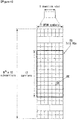
- FIG. 4 is a diagram illustrating a resource grid for one downlink slot in the wireless communication system to which the present invention can be applied.
- one downlink slot includes the plurality of OFDM symbols in the time domain.
- one downlink slot includes 7 OFDM symbols and one resource block includes 12 subcarriers in the frequency domain, but the present invention is not limited thereto.
- Each element on the resource grid is referred to as a resource element and one resource block includes 12 x 7 resource elements.
- the number of resource blocks included in the downlink slot, NDL is subordinated to a downlink transmission bandwidth.
- a structure of the uplink slot may be the same as that of the downlink slot.
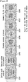
- FIG. 5 illustrates a structure of a downlink subframe in the wireless communication system to which the present invention can be applied.
- a maximum of three before OFDM symbols in the first slot of the sub frame is a control region to which control channels are allocated and residual OFDM symbols is a data region to which a physical downlink shared channel (PDSCH) is allocated.
- Examples of the downlink control channel used in the 3GPP LTE include a Physical Control Format Indicator Channel (PCFICH), a Physical Downlink Control Channel (PDCCH), a Physical Hybrid-ARQ Indicator Channel (PHICH), and the like.
- the PFCICH is transmitted in the first OFDM symbol of the subframe and transports information on the number (that is, the size of the control region) of OFDM symbols used for transmitting the control channels in the subframe.
- the PHICH which is a response channel to the uplink transports an Acknowledgement (ACK)/Not-Acknowledgement (NACK) signal for a hybrid automatic repeat request (HARQ).
- Control information transmitted through a PDCCH is referred to as downlink control information (DCI).
- the downlink control information includes uplink resource allocation information, downlink resource allocation information, or an uplink transmission (Tx) power control command for a predetermined terminal group.
- the PDCCH may transport A resource allocation and transmission format (also referred to as a downlink grant) of a downlink shared channel (DL-SCH), resource allocation information (also referred to as an uplink grant) of an uplink shared channel (UL-SCH), paging information in a paging channel (PCH), system information in the DL-SCH, resource allocation for an upper-layer control message such as a random access response transmitted in the PDSCH, an aggregate of transmission power control commands for individual terminals in the predetermined terminal group, a voice over IP (VoIP).
- a plurality of PDCCHs may be transmitted in the control region and the terminal may monitor the plurality of PDCCHs.
- the PDCCH is constituted by one or an aggregate of a plurality of continuous control channel elements (CCEs).
- the CCE is a logical allocation wise used to provide a coding rate depending on a state of a radio channel to the PDCCH.
- the CCEs correspond to a plurality of resource element groups.
- a format of the PDCCH and a bit number of usable PDCCH are determined according to an association between the number of CCEs and the coding rate provided by the CCEs.
- the base station determines the PDCCH format according to the DCI to be transmitted and attaches the control information to a cyclic redundancy check (CRC) to the control information.
- CRC cyclic redundancy check
- the CRC is masked with a unique identifier (referred to as a radio network temporary identifier (RNTI)) according to an owner or a purpose of the PDCCH.
- RNTI radio network temporary identifier
- the unique identifier of the terminal for example, a cell-RNTI (C-RNTI) may be masked with the CRC.
- a paging indication identifier for example, the CRC may be masked with a paging-RNTI (P-RNTI).
- P-RNTI paging-RNTI
- SIB system information block
- the CRC may be masked with a system information identifier, that is, a system information (SI)-RNTI.
- SI system information
- the CRC may be masked with a random access (RA)-RNTI in order to indicate the random access response which is a response to transmission of a random access preamble.
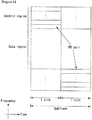
- FIG. 6 illustrates a structure of an uplink subframe in the wireless communication system to which the present invention can be applied.
- the uplink subframe may be divided into the control region and the data region in a frequency domain.
- a physical uplink control channel (PUCCH) transporting uplink control information is allocated to the control region.
- a physical uplink shared channel (PUSCH) transporting user data is allocated to the data region.
- One terminal does not simultaneously transmit the PUCCH and the PUSCH in order to maintain a single carrier characteristic.
- a resource block (RB) pair in the subframe are allocated to the PUCCH for one terminal.
- RBs included in the RB pair occupy different subcarriers in two slots, respectively.
- the RB pair allocated to the PUCCH frequency-hops in a slot boundary.
- Non-orthogonal multiple access basically refers to a multiple access scheme capable of obtaining excellent bandwidth efficiency by additionally allocating the same frequency-time resources to a plurality of UEs at a power ratio that has been previously considered and reducing interference between users that has been previously considered through an interference cancellation receiver compared to a method of allocating resources in the frequency-time domain in an existing OFDMA system under the premise of the interference cancellation receiver.
- the NOMA is a new radio access technology and has been mentioned as an important candidate technology of a 5G system in the future.
- FIG. 7 shows a conceptual diagram of an interference cancellation method used in a NOMA system to which a method proposed by this specification may be applied.
- an important configuration technology of the NOMA system may be basically divided into (1) a resource allocation method of an eNB and (2) an interference cancellation method of a UE.
- the interference cancellation method of a UE may include various forms, such as 1) a symbol-level interference cancellation receiver, 2) a maximum likelihood (ML) receiver, 3) a symbol-level interference cancellation (IC) receiver, 4) a codeword level interference cancellation (CWIC) receiver, 5) an MMSE-based linear CWIC (L-CWIC) and 6) ML-CWIC.
- ML maximum likelihood
- IC symbol-level interference cancellation
- CWIC codeword level interference cancellation
- L-CWIC MMSE-based linear CWIC
- L-CWIC MMSE-based linear CWIC
- the received gain of a UE is different in a given environment depending on each interference cancellation scheme.
- a gain if the ML scheme has been applied and in the CWIC type receiver is great in proportion to the implementation complexity of a UE.
- an energy per resource element that is, an energy value for each resource element.
- a value that is a criterion is the EPRE of a cell-specific reference signal (CRE).
- CRE cell-specific reference signal
- the EPRE of the resources of a physical data shared channel (PDSCH) through which actual data is transmitted may be expressed as a specific ratio of the CRS EPRE.
- the ratio of a CRS EPRE to a PDSCH EPRE is defined as ⁇ A .
- the ratio of a CRS EPRE to a PDSCH EPRE is defined as ⁇ B .
- FIG. 8 is a conceptual diagram showing an example of a method of controlling downlink power.
- a traverse axis indicates an OFDM symbol
- a longitudinal axis indicates a subcarrier
- the height indicates s power
- ⁇ A is determined by a power offset ⁇ power_offset and F A , that is, a UE-specific variable, depending on whether a multiple input multiple output (MIMO) scheme has been applied or not.
- ⁇ A/ ⁇ B is determined by the number of antenna ports and a cell-specific variable P B .
- ⁇ A is basically differently defined with respect to two types.
- ⁇ A ⁇ power ⁇ offset + P A + 10 log 10 2 dB
- ⁇ power_offset indicates a power offset value for supporting an MU-MIMO operation and is set to 0 dB in other PDSCH transmission cases.
- P A means a UE-specific variable as described above.
- ⁇ A ⁇ power ⁇ offset + P A dB
- FIG. 9 is a conceptual diagram showing an example of hierarchical modulation.
- HM Hierarchical modulation
- the HM may be called or expressed as layered modulation.
- the HM is one of technologies for multiplexing and modulating a plurality of data streams into a single symbol stream.
- base-layer subsymbols and enhancement-layer subsymbols are synchronized prior to transmission and thus superimposed.
- a user or user terminal having better reception and an enhanced receiver can demodulate and decode one or more data streams.
- a user terminal having an existing receiver or poor reception can demodulate and decode only a data stream transmitted in a low layer (e.g., a base layer).
- a low layer e.g., a base layer
- Hierarchical modulation is handled as one practical implementation in superposition precoding and has been proposed to achieve a maximum sum rate of a Gaussian broadcast channel having a successful interference cancellation in a reception stage (or receiver).
- a network operator may continuously target user terminals having different services or QoS when hierarchical modulation is applied.
- the ratio of existing hierarchical modulation which may be achieved by low-layer data streams is reduced due inter-layer interference (ILI) from a high layer signal(s).
- IIL inter-layer interference
- a base-layer throughput loss attributable to inter-layer interference may rises up to about 1.5 bits/symbol if the entire signal-to-noise ratio (SNR) is about 23 dB.
- SNR signal-to-noise ratio
- the demodulation error rate of any one of the base-layer and enhancement-layer symbols is also increased.
- a NOMA downlink (DL) system may be implemented by simultaneously transmitting a signal 1 corresponding to a desired signal transmitted from an eNB to an edge UE (e.g., UE0) and a signal 2 corresponding to a desired signal transmitted to a center UE (e.g., UE1) using a superposition coding scheme.
- the superposition coding scheme may be hierarchical modulation (HM), for example.
- the ratio of data power to CRS power may be calculated using ⁇ A , ⁇ B , as described in General NOMA.
- the UE1 (center UE) that has received additional power information for NOMA from the eNB may calculate power of the signal 2 (the desired signal of the UE1) and power of the signal 1 (an interference signal, the desired signal of the UE0) based on the values ⁇ A and ⁇ B .
- the ratio of P T to P 0 may be defined as a power ratio ⁇ .
- the total transmission power may be construed as being used in the desired signal of the UE0, that is, the signal 1.
- the total transmission power may be construed as being used in the desired signal of the UE1, that is, the signal 2.
- P 0 may be set greater than P 1 because a channel state between the UE1 and the eNB may be said to be better than that between the UE0 and the eNB.
- the value ⁇ may have a value, such as 0.5 ⁇ ⁇ ⁇ 1.
- the desired signal (signal 1) of the UE0 may experience great interference in a specific power (size) and specific phase due to the desired signal (signal 2) of the UE1 (from a viewpoint of a modulation symbol).
- the UE0 may be difficult for the UE0 to decode the signal 1 because the signal 1 is considered to be Gaussian noise.
- this specification provides a method of decoding the desired signal of the UE0 by considering the signal 2 to be Gaussian noise in such a manner that the power (size) and phase of the modulation symbol of the desired signal (signal 2) of the UE1 acting as interference is changed at a specific interval according to a specific rule known to the eNB and the UE1.
- a method of changing the signal of a counterpart UE into Gaussian noise may be basically divided into (1) a method of changing a phase, (2) a method of changing power (size), (3) a method of simultaneously changing a phase and power (size), and (4) a scrambling method using a random sequence, that is, four methods.
- the method 1 is a method of changing the phase of a modulation symbol of the desired signal (signal 1) of the UE1 according to a specific rule known to the eNB and the UE1.
- a phase changed according to a specific rule is hereinafter called or expressed as a 'phase difference' or 'change phase', for convenience sake.
- the phase difference value of the signal 2 may be set as a previously agreed value A.
- phase difference of an RE next to the RE in which the data symbol mapping starts may be increased and set by a fixed value, such as 46 180 ⁇ .
- phase difference of an i-th RE in which data symbol mapping is performed in each RB may be generated and expressed as A + ix 46 180 ⁇ .
- the fixed value 46 180 ⁇ is set based on ⁇ 4 which may be located between existing constellations because the configuration of an existing constellation (QPSK, 16QAM, 64QAM, etc.) is disposed at intervals of ⁇ 2 , and may be set as a value greater than ⁇ 180 greater than the value ⁇ 4 . Accordingly, the fixed value is set so that it has all of phase values having resolution of ⁇ 180 for each RE.
- a phase difference having resolution of a previously agreed value ⁇ may be set based on a previously agreed value ⁇ .
- phase difference value starts at a previously agreed value A.
- the phase difference of a next RE after the data symbol was mapped may be set as a value which varies depending on the results of a previously agreed function between the eNB and the UE1 based on the ID of the UE1 and a current subframe number.
- a phase difference value is set as a value varying as described above, the UE1 can decode the signal 2 corresponding to the desired signal of the UE1 because the eNB and the UE1 assume that they are accurately aware of the phase difference value.
- the UE0 considers the interference of the UE1 to be Gaussian noise compared to an existing method because the phase of the desired signal of the UE1, that is, the signal 2 acting as interference in a conventional technology, is shifted for each RE, thus being capable of expecting performance improvement for the decoding of the signal 1.
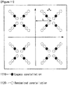
- FIG. 10 is a diagram showing an example of a constellation randomized using a phase difference proposed by this specification.
- a dark portion 1010 shows a legacy constellation
- a portion 1020 indicated by a dotted line shows a randomized constellation
- the method 2 is a method of controlling the power (size) of a modulation symbol of the desired signal of the UE1, that is, the signal 2, according to a specific rule known to the eNB and the UE1.
- Power (size) changed according to a specific rule is hereinafter called or expressed as a 'power difference' or 'changed power', for convenience sake.
- a power difference value may be set as A.
- the power difference of an RE next to the RE in which the data symbol mapping starts may be set as a fixed value, such as "a*P 1,Previous .”
- a power difference value may start from A.
- the power difference of an RE to which a next data symbol has been mapped may be set as a varying value, such as "F(x, y, ...,)*P 1,previous .”
- F(x, y, ...,) may indicate a previously agreed function
- the input of the corresponding function may be the ID of the UE1 or a current subframe number
- P 1,previous may indicate transmission power of a right-before RE.
- the UE1 has no great difficult in decoding its desired signal, that is, the signal 2, because the UE1 and the eNB assume that they are accurately aware of the power difference value.
- the UE0 considers the interference of the UE1 to be Gaussian noise compared to an existing method because the power (size) of the desired signal of the UE1 (signal 2) acting as interference in a conventional technology is controlled for each RE, thus being capable of expecting performance improvement for the decoding of the signal 1.
- FIG. 11 is a diagram showing an example of a constellation randomized using a difference in the power size proposed by this specification.
- a dark portion 1110 shows a legacy constellation
- a portion 1120 indicated by a dotted line shows a randomized constellation
- Method 3 Method of simultaneously changing phase and power size of signal
- the method 3 is a method of applying the method 1 and the method 2 together.
- the method 3 is a method of changing the phase and power (size) of a modulation symbol of the desired signal of the UE1 (signal 2) according to a specific rule known to the eNB and the UE1.
- a phase difference value starts at a previously agreed value A and a power difference value starts at a previously agreed value B.
- the phase difference of a next RE after the data symbol was mapped may be set as a fixed value, such as 46 180 ⁇
- the power difference thereof may be set as a fixed value, such as a*P 1,previous ("a" is a previously agreed constant and P 1,previous is transmission power of a right-before RE).
- phase difference value starts at a previously agreed value A and a power difference value starts at a previously agreed value B.
- the phase difference of a next RE after the data symbol was mapped may be set as a value varying depending on the results of a previously agreed function and the power difference thereof may be set as a value, such as F(A, B, ...,)* P1,previous , based on the ID of the UE1 and a current subframe number.
- F(x, y, ...,) may indicate a previously agreed function
- the input of the corresponding function may be the ID of the UE1 or a current subframe number
- P 1,previous may indicate transmission power of a right-before RE.
- one of the phase difference and the power difference may be set as a fixed value, and the other thereof may be set as a varying value.
- the UE1 has no great difficulty in decoding its desired signal, that is, the signal 2, because the eNB and the UE1 assume that they are accurately ware of the phase difference value and the power difference value.
- the UE0 considers the interference of the UE1 to be Gaussian noise compared to an existing method because the phase of the desired signal of the UE1 (signal 2) acting as interference in a conventional technology is shifted for each RE and the power (size) of the desired signal of the UE1 (signal 2) is controlled, thus being capable of expecting performance improvement for the decoding of the signal 1.
- FIG. 12 is a diagram showing an example of a constellation randomized using a phase difference and power (size) difference proposed by this specification.
- a dark portion 1210 shows a legacy constellation and a portion 1220 indicated by a dotted line shows a randomized constellation.
- the sequence generated using the random number generator may be a pseudo random number (PN) sequence, for example.
- PN pseudo random number
- an existing constellation e.g., QPSK, 16QAM or 64QAM
- complex scrambling may be performed on all of REs in which the data symbol mapping of each resource block (RB) has been performed using one constellation value of n-PSK constellations corresponding to a corresponding sequence value based on a PN sequence A(m) (m is the length of a sequence) known to the eNB and the UE1.
- the length of the PN sequence may have an agreed size set so that randomization can be initialized.
- the UE1 has no great difficulty in decoding its desired signal (signal 2) because the eNB and the UE1 assume that they are accurately aware of the PN sequence and the n-PSK constellation.
- the UE0 considers the interference of the UE1 to be Gaussian noise compared to an existing method because the desired signal of the UE1 (signal 2) acting as interference in a conventional technology is subjected to complex scrambling for each RE, thus being capable of expecting performance improvement when decoding the signal 1.
- the signal 2 may be randomized for each RE, but may be randomized for each greater resource unit (e.g., an RB, a resource block group (RBG) or a subband).
- resource unit e.g., an RB, a resource block group (RBG) or a subband.
- the UE1 can expect that error propagation is reduced if randomization is set to be periodically initialized when a size (an interval greater than a basic unit) agreed between the eNB and the UE1 is exceeded although which resource unit is used.
- phase difference value and power difference value in the method 1 to the method 4 may be set to be formed in a table form, such as a phase difference table and power difference table known to the eNB and the UE1.
- a corresponding phase difference value and power difference value may be determined while changing an index for each resource unit within each set table.
- the UE1 may receive a variety of the aforementioned information (e.g., the initial phase value, initial power value, phase difference, power difference, PN sequence, n-PSK constellation and table index) through a specific message or channel from the eNB.
- the aforementioned information e.g., the initial phase value, initial power value, phase difference, power difference, PN sequence, n-PSK constellation and table index
- the specific message or channel may be high layer signaling (e.g., RRC signaling), a new field on a predetermined channel (e.g., a PDSCH), and a new combination of existing field values on a predetermined channel, for example.
- RRC signaling e.g., RRC signaling
- a new field on a predetermined channel e.g., a PDSCH
- a new combination of existing field values on a predetermined channel for example.
- y 0 H 0 x 0 + H 0 x 1 + n 0
- the UE0 can expect performance improvement compared to an existing method if it considers x 1 to be Gaussian noise like H 0 ⁇ 1 n 0 and decodes x 0 .
- the aforementioned methods may be applied to not only the UE1, but the UE0 and may be applied to the UE0 and the UE1 at the same time using a different phase difference, a power difference, a PN sequence and so on.
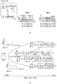
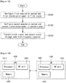
- FIG. 13 is a flowchart showing an example of a method for transmitting/receiving data using a non-orthogonal multiple access (NOMA) method proposed by this specification.
- NOMA non-orthogonal multiple access
- an eNB configures a first modulation method and first transmission power in a first signal to be transmitted to a first UE (S1310).
- NOMA non-orthogonal multiple access
- the first UE may mean the UE0 corresponding to the aforementioned center UE
- the first signal may mean the desired signal of the UE0, that is, the first signal.
- the first transmission power may mean transmission power of the first signal.
- the eNB configures a second modulation method and second transmission power in a second signal to be transmitted to a second UE (S1320).
- the second UE may mean the UE1 corresponding to the aforementioned edge UE
- the second signal may mean the desired signal of the UE1, that is, the second signal.
- the second transmission power may mean transmission power of the second signal.
- the eNB maps the first signal and the second signal to the same time-frequency resource and transmits them to the first UE and/or the second UE (S1330).
- the eNB transmits control information related to the cancellation of interference generated in the second UE due to the first signal.
- the control information includes at least one of phase information related to a change in the phase of a modulation symbol of the second signal modulated by the second modulation method, power information related to a change in the power size of the modulation symbol of the second signal modulated by the second modulation method, and sequence information related to a random sequence for scrambling the modulation symbol of the second signal modulated by the second modulation method.
- the phase information may include an initial phase value and a changed phase value
- the power information may include an initial power size value and a change power size value
- control information may be transmitted through high layer signaling or a physical downlink channel.
- the physical downlink channel may be a PDSCH.
- control information may be transmitted only when the first transmission power and the second transmission power are the same or a difference between the first transmission power and the second transmission power falls within a range of a specific value.
- the unit of the same time-frequency resource may be a resource element (RE), a resource block (RB), a resource block group (RBG) or a subband.
- RE resource element
- RB resource block
- RBG resource block group
- the eNB may change at least one of the phase or power size of a modulation symbol of the second signal modulated by the second modulation method.
- the eNB may set a phase value corresponding to the second modulation method as a fixed value in a resource in which data symbol mapping starts and may increase the set phase value by a specific phase value every resource from a resource subsequent to the resource in which the data symbol mapping starts.
- the specific phase value may be a fixed value or changed value.
- the specific phase value may be set based on at least one of the ID of the second UE and a subframe number in which the second signal is received.
- the specific value may be a value 46 180 ⁇ for example.
- the eNB may set the value of a power size corresponding to the second transmission power as a fixed value in a resource in which data symbol mapping starts and may change the size of the transmission power based on transmission power in a previous resource or a specific function from a resource subsequent to the resource in which the data symbol mapping starts.
- FIG. 14 illustrates a block configuration diagram of a wireless communication device to which the methods proposed by this specification may be applied.
- the wireless communication system includes an eNB 1410 and a plurality of UEs 1420 located within the area of the eNB 1410.
- the UE 1420 may correspond to the aforementioned terminal, node, device, RRH, relay, TP/RP or RSU.
- the eNB 1410 includes a processor 1411, memory 1412 and a radio frequency (RF) unit 1413.
- the processor 1411 implements the functions, processes and/or methods proposed in FIGS. 1 to 13 .
- the layers of a radio interface protocol may be implemented by the processor 1411.
- the memory 1412 is connected to the processor 1411 and stores a variety of types of information for driving the processor 1411.
- the RF unit 1413 is connected to the processor 1411 and transmits and/or receives a radio signal.
- the UE 1420 includes a processor 1421, memory 1422 and an RF unit 1423.
- the processor 1421 implements the functions, processes and/or methods proposed in FIGS. 1 to 13 .
- the layers of a radio interface protocol may be implemented by the processor 1421.
- the memory 1422 is connected to the processor 1421 and stores a variety of types of information for driving the processor 1421.
- the RF unit 1423 is connected to the processor 1421 and transmits and/or receives a radio signal.
- the memory 1412, 1422 may be located inside or outside the processor 1411, 1421 and may be connected to the processor 1411, 1421 by means of well-known various means. Furthermore, the eNB 1410 and/or the UE 1420 may have a single antenna or multiple antenna.
- An embodiment of the present invention may be implemented by various means, for example, hardware, firmware, software or a combination of them.
- an embodiment of the present invention may be implemented using one or more application-specific integrated circuits (ASICs), digital signal processors (DSPs), digital signal processing devices (DSPDs), programmable logic devices (PLDs), field programmable gate arrays (FPGAs), processors, controllers, microcontrollers and/or microprocessors.
- ASICs application-specific integrated circuits
- DSPs digital signal processors
- DSPDs digital signal processing devices
- PLDs programmable logic devices
- FPGAs field programmable gate arrays
- processors controllers, microcontrollers and/or microprocessors.
- an embodiment of the present invention may be implemented in the form of a module, procedure, or function for performing the aforementioned functions or operations.
- Software code may be stored in memory and driven by a processor.
- the memory may be located inside or outside the processor, and may exchange data with the processor through a variety of known means.
- the scheme for transmitting/receiving data has been illustrated as being applied to the 3GPP LTE/LTE-A systems, but may be applied to various wireless communication systems in addition to the 3GPP LTE/LTE-A system.
Landscapes
- Engineering & Computer Science (AREA)
- Signal Processing (AREA)
- Computer Networks & Wireless Communication (AREA)
- Quality & Reliability (AREA)
- Mobile Radio Communication Systems (AREA)
Applications Claiming Priority (2)
| Application Number | Priority Date | Filing Date | Title |
|---|---|---|---|
| US201562137210P | 2015-03-23 | 2015-03-23 | |
| PCT/KR2016/002849 WO2016153250A1 (fr) | 2015-03-23 | 2016-03-22 | Procédé et dispositif permettant d'émettre et de recevoir des données à l'aide d'un accès multiple non orthogonal dans un système de communication sans fil |
Publications (3)
| Publication Number | Publication Date |
|---|---|
| EP3276902A1 true EP3276902A1 (fr) | 2018-01-31 |
| EP3276902A4 EP3276902A4 (fr) | 2018-11-21 |
| EP3276902B1 EP3276902B1 (fr) | 2021-11-10 |
Family
ID=56977598
Family Applications (1)
| Application Number | Title | Priority Date | Filing Date |
|---|---|---|---|
| EP16769068.4A Active EP3276902B1 (fr) | 2015-03-23 | 2016-03-22 | Procédé et dispositif de transmission et reception des données à l'aide d'un accès multiple non orthogonal dans un système de communication sans fil |
Country Status (4)
| Country | Link |
|---|---|
| US (1) | US10432345B2 (fr) |
| EP (1) | EP3276902B1 (fr) |
| CN (1) | CN107466460B (fr) |
| WO (1) | WO2016153250A1 (fr) |
Cited By (2)
| Publication number | Priority date | Publication date | Assignee | Title |
|---|---|---|---|---|
| US11457413B2 (en) * | 2018-01-25 | 2022-09-27 | Huawei Technologies Co., Ltd. | Power control method and apparatus |
| US12265385B2 (en) | 2018-11-06 | 2025-04-01 | Battelle Energy Alliance, Llc | Systems, devices, and methods for millimeter wave communication for unmanned aerial vehicles |
Families Citing this family (17)
| Publication number | Priority date | Publication date | Assignee | Title |
|---|---|---|---|---|
| KR102322769B1 (ko) * | 2014-08-18 | 2021-11-10 | 삼성전자 주식회사 | 무선 통신 시스템에서 단말의 d2d 탐색 신호 송신방법 |
| US20190068342A1 (en) * | 2016-01-29 | 2019-02-28 | Nokia Solutions And Networks Oy | Communication efficiency |
| US11329691B2 (en) | 2016-08-11 | 2022-05-10 | Mediatek Inc. | Non-orthogonal multiple access wireless communications methods and apparatus thereof |
| US20190132165A1 (en) * | 2017-11-01 | 2019-05-02 | Industrial Technology Research Institute | Method of receiving or transmitting data by ue or base station under noma scheme, ue using the same and base station using the same |
| WO2019191869A1 (fr) * | 2018-04-02 | 2019-10-10 | 富士通株式会社 | Procédé et dispositif de transmission et de réception d'informations, et système de communication |
| US11424799B2 (en) | 2018-06-12 | 2022-08-23 | Google Llc | Beamforming-based grant-free non-orthogonal multiple access transmission |
| CN112005515B (zh) | 2018-06-15 | 2023-03-24 | 谷歌有限责任公司 | 用于无线网络的基于cbg的noma传输 |
| US11711194B2 (en) | 2018-06-22 | 2023-07-25 | Google Llc | Multi-branch NOMA wireless communication |
| CN110798289B (zh) * | 2018-08-01 | 2022-08-26 | 联发科技股份有限公司 | 用于无线通信的方法 |
| CN112514517B (zh) | 2018-08-10 | 2024-06-04 | 谷歌有限责任公司 | 用于noma异步传输中的上行链路控制信道的方法和装置 |
| WO2020069090A1 (fr) | 2018-09-26 | 2020-04-02 | Google Llc | Configuration d'accès multiple non orthogonal dans des architectures de stations de base divisées |
| CN109560844B (zh) * | 2018-11-19 | 2021-10-15 | 浙江万里学院 | 一种基于非正交多址接入技术的多用户中继传输方法 |
| CN110062359B (zh) * | 2019-04-02 | 2022-02-11 | 重庆邮电大学 | Mtc中基于noma短编码块传输的高可靠低迟延无线资源分配优化方法 |
| WO2020242898A1 (fr) | 2019-05-26 | 2020-12-03 | Genghiscomm Holdings, LLC | Accès multiple non orthogonal |
| CN113518430B (zh) * | 2020-04-09 | 2022-07-05 | 王晋良 | 支持基于点阵划分的非正交多重接取的基站及调制方法 |
| CN112286494B (zh) * | 2020-11-17 | 2024-05-24 | Oppo广东移动通信有限公司 | 伪随机序列的生成方法、生成装置及计算机可读存储介质 |
| WO2025025016A1 (fr) * | 2023-07-28 | 2025-02-06 | Oppo广东移动通信有限公司 | Procédé de communication sans fil et dispositif de communication |
Family Cites Families (13)
| Publication number | Priority date | Publication date | Assignee | Title |
|---|---|---|---|---|
| US8179876B2 (en) * | 2004-12-22 | 2012-05-15 | Qualcomm Incorporated | Multiple modulation technique for use in a communication system |
| GB2438347B8 (en) * | 2005-02-25 | 2009-04-08 | Data Fusion Corp | Mitigating interference in a signal |
| JP5154295B2 (ja) * | 2008-05-02 | 2013-02-27 | 株式会社エヌ・ティ・ティ・ドコモ | 基地局装置及びユーザ装置並びに通信制御方法 |
| GB0916911D0 (en) | 2009-09-25 | 2009-11-11 | Icera Inc | Cancelling interference in a wireless cellular network |
| EP2375580B1 (fr) * | 2010-03-29 | 2016-10-12 | Sequans Communications | Procédé et appareil pour optimiser la diversité de transmission |
| JP5864200B2 (ja) * | 2011-05-20 | 2016-02-17 | 株式会社Nttドコモ | 受信装置、送信装置及び無線通信方法 |
| JP5586538B2 (ja) * | 2011-07-29 | 2014-09-10 | 株式会社東芝 | 無線送信装置 |
| JP6050028B2 (ja) * | 2012-05-25 | 2016-12-21 | シャープ株式会社 | 端末、基地局、通信方法及び集積回路 |
| JP5894105B2 (ja) * | 2013-04-04 | 2016-03-23 | 株式会社Nttドコモ | 無線基地局、ユーザ端末及び無線通信方法 |
| KR102070938B1 (ko) | 2013-04-19 | 2020-01-29 | 삼성전자주식회사 | 다중 사용자 빔포밍 시스템에서 비 직교 다중 접속 기법을 운용하기 위한 방법 및 장치 |
| KR20160019867A (ko) * | 2014-08-12 | 2016-02-22 | 뉴라컴 인코포레이티드 | 고효율 무선랜 디바이스 전송 전력 제어 |
| CN104158631B (zh) * | 2014-08-27 | 2018-04-10 | 北京邮电大学 | 一种数据流的发射方法及装置 |
| WO2016131164A1 (fr) * | 2015-02-16 | 2016-08-25 | 富士通株式会社 | Procédé d'émission de signal, dispositif et système de communications |
-
2016
- 2016-03-22 WO PCT/KR2016/002849 patent/WO2016153250A1/fr not_active Ceased
- 2016-03-22 CN CN201680017692.8A patent/CN107466460B/zh active Active
- 2016-03-22 US US15/560,828 patent/US10432345B2/en active Active
- 2016-03-22 EP EP16769068.4A patent/EP3276902B1/fr active Active
Cited By (3)
| Publication number | Priority date | Publication date | Assignee | Title |
|---|---|---|---|---|
| US11457413B2 (en) * | 2018-01-25 | 2022-09-27 | Huawei Technologies Co., Ltd. | Power control method and apparatus |
| US11871354B2 (en) | 2018-01-25 | 2024-01-09 | Huawei Technologies Co., Ltd. | Power control method and apparatus |
| US12265385B2 (en) | 2018-11-06 | 2025-04-01 | Battelle Energy Alliance, Llc | Systems, devices, and methods for millimeter wave communication for unmanned aerial vehicles |
Also Published As
| Publication number | Publication date |
|---|---|
| EP3276902A4 (fr) | 2018-11-21 |
| CN107466460B (zh) | 2021-06-08 |
| WO2016153250A1 (fr) | 2016-09-29 |
| EP3276902B1 (fr) | 2021-11-10 |
| US10432345B2 (en) | 2019-10-01 |
| US20180115386A1 (en) | 2018-04-26 |
| CN107466460A (zh) | 2017-12-12 |
Similar Documents
| Publication | Publication Date | Title |
|---|---|---|
| EP3276902B1 (fr) | Procédé et dispositif de transmission et reception des données à l'aide d'un accès multiple non orthogonal dans un système de communication sans fil | |
| EP3506543B1 (fr) | Procédé et dispositif de transmission et de réception de pscch et de pssch par un terminal dans un système de communication sans fil | |
| US9549395B2 (en) | Method for dynamic allocation of radio resources in wireless communication system and device therefor | |
| US11310639B2 (en) | Method and device for V2X terminal to receive PSCCH scheduling information and transmit PSCCH in wireless communication system | |
| US11115965B2 (en) | Method and apparatus for transmitting and receiving data using non-orthogonal multiple access in wireless communication system | |
| EP3624511B1 (fr) | Procédé de transmission de signal de synchronisation et de canal de synchronisation dans un système de communication sans fil prenant en charge une communication de dispositif à dispositif et appareil correspondant | |
| US9730240B2 (en) | Communication method considering carrier type and apparatus for same | |
| US9614653B2 (en) | Method and apparatus for performing Quasi Co-Location in wireless access system | |
| US11115938B2 (en) | Method and apparatus for transceiving signal of device-to-device communication terminal in wireless communication system | |
| EP2696521B1 (fr) | Procédé de transmission d'informations de commande de liaison montante dans un système de communication sans fil et dispositif correspondant | |
| US9282552B2 (en) | Method for transmitting and receiving control information in a wireless communication system, and apparatus for same | |
| US10541848B2 (en) | Method and apparatus for generating and transmitting reference signal and data in wireless communication system | |
| EP3297204B1 (fr) | Procédé et appareil d'émission/réception de signal de détection de terminal de communication de dispositif à dispositif dans un système de communication sans fil | |
| EP2670070A2 (fr) | Procédé et dispositif de maîtrise de brouillage entre cellules dans un système de communication sans fil | |
| EP3146650A1 (fr) | Procédé et appareil pour transmettre des données de liaison montante dans un système de communication sans fil | |
| US11265877B2 (en) | Method for selecting transmission resource for transport block by user equipment in wireless communication system and apparatus therefor | |
| US20180175968A1 (en) | Method and apparatus for transmitting and receiving signal using non-orthogonal multiple access in wireless communication system | |
| EP3122135A1 (fr) | Terminal et procédé permettant d'émettre un signal de dispositif à dispositif (d2d) pour la communication d2d dans un système d'accès sans fil prenant en charge la communication d2d | |
| KR20160040580A (ko) | 무선 통신 시스템에서 신호 송수신방법 및 장치 | |
| CN110383931B (zh) | 无线通信系统中基于lte和nr发送和接收信号的方法及其设备 | |
| CN113596787A (zh) | 执行侧链路传输的方法、用户设备和处理设备 | |
| US10652909B2 (en) | Method and device for transmitting data and control information of terminal in wireless communication system | |
| US10349298B2 (en) | Method for ordering measuring of inter-device interference in wireless communication system, and device for same | |
| KR102448867B1 (ko) | 풀-듀플렉스 무선 통신 시스템에서 시간 비동기 환경을 고려한 자기 간섭 제거 방법 및 이를 위한 장치 | |
| KR20140044358A (ko) | 무선통신 시스템에서 comp 동작을 수행하는 단말이 pusch를 전송하는 방법 및 그 단말 |
Legal Events
| Date | Code | Title | Description |
|---|---|---|---|
| STAA | Information on the status of an ep patent application or granted ep patent |
Free format text: STATUS: THE INTERNATIONAL PUBLICATION HAS BEEN MADE |
|
| PUAI | Public reference made under article 153(3) epc to a published international application that has entered the european phase |
Free format text: ORIGINAL CODE: 0009012 |
|
| STAA | Information on the status of an ep patent application or granted ep patent |
Free format text: STATUS: REQUEST FOR EXAMINATION WAS MADE |
|
| 17P | Request for examination filed |
Effective date: 20170922 |
|
| AK | Designated contracting states |
Kind code of ref document: A1 Designated state(s): AL AT BE BG CH CY CZ DE DK EE ES FI FR GB GR HR HU IE IS IT LI LT LU LV MC MK MT NL NO PL PT RO RS SE SI SK SM TR |
|
| AX | Request for extension of the european patent |
Extension state: BA ME |
|
| DAV | Request for validation of the european patent (deleted) | ||
| DAX | Request for extension of the european patent (deleted) | ||
| A4 | Supplementary search report drawn up and despatched |
Effective date: 20181024 |
|
| RIC1 | Information provided on ipc code assigned before grant |
Ipc: H04L 27/26 20060101ALI20181018BHEP Ipc: H04L 1/00 20060101ALI20181018BHEP Ipc: H04L 5/00 20060101ALI20181018BHEP Ipc: H04L 27/00 20060101AFI20181018BHEP Ipc: H04W 52/14 20090101ALI20181018BHEP Ipc: H04L 27/34 20060101ALI20181018BHEP |
|
| STAA | Information on the status of an ep patent application or granted ep patent |
Free format text: STATUS: EXAMINATION IS IN PROGRESS |
|
| 17Q | First examination report despatched |
Effective date: 20200616 |
|
| GRAP | Despatch of communication of intention to grant a patent |
Free format text: ORIGINAL CODE: EPIDOSNIGR1 |
|
| STAA | Information on the status of an ep patent application or granted ep patent |
Free format text: STATUS: GRANT OF PATENT IS INTENDED |
|
| INTG | Intention to grant announced |
Effective date: 20210615 |
|
| GRAS | Grant fee paid |
Free format text: ORIGINAL CODE: EPIDOSNIGR3 |
|
| GRAA | (expected) grant |
Free format text: ORIGINAL CODE: 0009210 |
|
| STAA | Information on the status of an ep patent application or granted ep patent |
Free format text: STATUS: THE PATENT HAS BEEN GRANTED |
|
| AK | Designated contracting states |
Kind code of ref document: B1 Designated state(s): AL AT BE BG CH CY CZ DE DK EE ES FI FR GB GR HR HU IE IS IT LI LT LU LV MC MK MT NL NO PL PT RO RS SE SI SK SM TR |
|
| REG | Reference to a national code |
Ref country code: GB Ref legal event code: FG4D |
|
| REG | Reference to a national code |
Ref country code: AT Ref legal event code: REF Ref document number: 1447103 Country of ref document: AT Kind code of ref document: T Effective date: 20211115 Ref country code: CH Ref legal event code: EP |
|
| REG | Reference to a national code |
Ref country code: DE Ref legal event code: R096 Ref document number: 602016066049 Country of ref document: DE |
|
| REG | Reference to a national code |
Ref country code: IE Ref legal event code: FG4D |
|
| REG | Reference to a national code |
Ref country code: LT Ref legal event code: MG9D |
|
| REG | Reference to a national code |
Ref country code: NL Ref legal event code: MP Effective date: 20211110 |
|
| REG | Reference to a national code |
Ref country code: AT Ref legal event code: MK05 Ref document number: 1447103 Country of ref document: AT Kind code of ref document: T Effective date: 20211110 |
|
| PG25 | Lapsed in a contracting state [announced via postgrant information from national office to epo] |
Ref country code: RS Free format text: LAPSE BECAUSE OF FAILURE TO SUBMIT A TRANSLATION OF THE DESCRIPTION OR TO PAY THE FEE WITHIN THE PRESCRIBED TIME-LIMIT Effective date: 20211110 Ref country code: LT Free format text: LAPSE BECAUSE OF FAILURE TO SUBMIT A TRANSLATION OF THE DESCRIPTION OR TO PAY THE FEE WITHIN THE PRESCRIBED TIME-LIMIT Effective date: 20211110 Ref country code: FI Free format text: LAPSE BECAUSE OF FAILURE TO SUBMIT A TRANSLATION OF THE DESCRIPTION OR TO PAY THE FEE WITHIN THE PRESCRIBED TIME-LIMIT Effective date: 20211110 Ref country code: BG Free format text: LAPSE BECAUSE OF FAILURE TO SUBMIT A TRANSLATION OF THE DESCRIPTION OR TO PAY THE FEE WITHIN THE PRESCRIBED TIME-LIMIT Effective date: 20220210 Ref country code: AT Free format text: LAPSE BECAUSE OF FAILURE TO SUBMIT A TRANSLATION OF THE DESCRIPTION OR TO PAY THE FEE WITHIN THE PRESCRIBED TIME-LIMIT Effective date: 20211110 |
|
| PG25 | Lapsed in a contracting state [announced via postgrant information from national office to epo] |
Ref country code: IS Free format text: LAPSE BECAUSE OF FAILURE TO SUBMIT A TRANSLATION OF THE DESCRIPTION OR TO PAY THE FEE WITHIN THE PRESCRIBED TIME-LIMIT Effective date: 20220310 Ref country code: SE Free format text: LAPSE BECAUSE OF FAILURE TO SUBMIT A TRANSLATION OF THE DESCRIPTION OR TO PAY THE FEE WITHIN THE PRESCRIBED TIME-LIMIT Effective date: 20211110 Ref country code: PT Free format text: LAPSE BECAUSE OF FAILURE TO SUBMIT A TRANSLATION OF THE DESCRIPTION OR TO PAY THE FEE WITHIN THE PRESCRIBED TIME-LIMIT Effective date: 20220310 Ref country code: PL Free format text: LAPSE BECAUSE OF FAILURE TO SUBMIT A TRANSLATION OF THE DESCRIPTION OR TO PAY THE FEE WITHIN THE PRESCRIBED TIME-LIMIT Effective date: 20211110 Ref country code: NO Free format text: LAPSE BECAUSE OF FAILURE TO SUBMIT A TRANSLATION OF THE DESCRIPTION OR TO PAY THE FEE WITHIN THE PRESCRIBED TIME-LIMIT Effective date: 20220210 Ref country code: NL Free format text: LAPSE BECAUSE OF FAILURE TO SUBMIT A TRANSLATION OF THE DESCRIPTION OR TO PAY THE FEE WITHIN THE PRESCRIBED TIME-LIMIT Effective date: 20211110 Ref country code: LV Free format text: LAPSE BECAUSE OF FAILURE TO SUBMIT A TRANSLATION OF THE DESCRIPTION OR TO PAY THE FEE WITHIN THE PRESCRIBED TIME-LIMIT Effective date: 20211110 Ref country code: HR Free format text: LAPSE BECAUSE OF FAILURE TO SUBMIT A TRANSLATION OF THE DESCRIPTION OR TO PAY THE FEE WITHIN THE PRESCRIBED TIME-LIMIT Effective date: 20211110 Ref country code: GR Free format text: LAPSE BECAUSE OF FAILURE TO SUBMIT A TRANSLATION OF THE DESCRIPTION OR TO PAY THE FEE WITHIN THE PRESCRIBED TIME-LIMIT Effective date: 20220211 Ref country code: ES Free format text: LAPSE BECAUSE OF FAILURE TO SUBMIT A TRANSLATION OF THE DESCRIPTION OR TO PAY THE FEE WITHIN THE PRESCRIBED TIME-LIMIT Effective date: 20211110 |
|
| PG25 | Lapsed in a contracting state [announced via postgrant information from national office to epo] |
Ref country code: SM Free format text: LAPSE BECAUSE OF FAILURE TO SUBMIT A TRANSLATION OF THE DESCRIPTION OR TO PAY THE FEE WITHIN THE PRESCRIBED TIME-LIMIT Effective date: 20211110 Ref country code: SK Free format text: LAPSE BECAUSE OF FAILURE TO SUBMIT A TRANSLATION OF THE DESCRIPTION OR TO PAY THE FEE WITHIN THE PRESCRIBED TIME-LIMIT Effective date: 20211110 Ref country code: RO Free format text: LAPSE BECAUSE OF FAILURE TO SUBMIT A TRANSLATION OF THE DESCRIPTION OR TO PAY THE FEE WITHIN THE PRESCRIBED TIME-LIMIT Effective date: 20211110 Ref country code: EE Free format text: LAPSE BECAUSE OF FAILURE TO SUBMIT A TRANSLATION OF THE DESCRIPTION OR TO PAY THE FEE WITHIN THE PRESCRIBED TIME-LIMIT Effective date: 20211110 Ref country code: DK Free format text: LAPSE BECAUSE OF FAILURE TO SUBMIT A TRANSLATION OF THE DESCRIPTION OR TO PAY THE FEE WITHIN THE PRESCRIBED TIME-LIMIT Effective date: 20211110 Ref country code: CZ Free format text: LAPSE BECAUSE OF FAILURE TO SUBMIT A TRANSLATION OF THE DESCRIPTION OR TO PAY THE FEE WITHIN THE PRESCRIBED TIME-LIMIT Effective date: 20211110 |
|
| REG | Reference to a national code |
Ref country code: DE Ref legal event code: R097 Ref document number: 602016066049 Country of ref document: DE |
|
| PLBE | No opposition filed within time limit |
Free format text: ORIGINAL CODE: 0009261 |
|
| STAA | Information on the status of an ep patent application or granted ep patent |
Free format text: STATUS: NO OPPOSITION FILED WITHIN TIME LIMIT |
|
| 26N | No opposition filed |
Effective date: 20220811 |
|
| PG25 | Lapsed in a contracting state [announced via postgrant information from national office to epo] |
Ref country code: MC Free format text: LAPSE BECAUSE OF FAILURE TO SUBMIT A TRANSLATION OF THE DESCRIPTION OR TO PAY THE FEE WITHIN THE PRESCRIBED TIME-LIMIT Effective date: 20211110 Ref country code: AL Free format text: LAPSE BECAUSE OF FAILURE TO SUBMIT A TRANSLATION OF THE DESCRIPTION OR TO PAY THE FEE WITHIN THE PRESCRIBED TIME-LIMIT Effective date: 20211110 |
|
| REG | Reference to a national code |
Ref country code: CH Ref legal event code: PL |
|
| GBPC | Gb: european patent ceased through non-payment of renewal fee |
Effective date: 20220322 |
|
| PG25 | Lapsed in a contracting state [announced via postgrant information from national office to epo] |
Ref country code: SI Free format text: LAPSE BECAUSE OF FAILURE TO SUBMIT A TRANSLATION OF THE DESCRIPTION OR TO PAY THE FEE WITHIN THE PRESCRIBED TIME-LIMIT Effective date: 20211110 |
|
| REG | Reference to a national code |
Ref country code: BE Ref legal event code: MM Effective date: 20220331 |
|
| PG25 | Lapsed in a contracting state [announced via postgrant information from national office to epo] |
Ref country code: LU Free format text: LAPSE BECAUSE OF NON-PAYMENT OF DUE FEES Effective date: 20220322 Ref country code: LI Free format text: LAPSE BECAUSE OF NON-PAYMENT OF DUE FEES Effective date: 20220331 Ref country code: IE Free format text: LAPSE BECAUSE OF NON-PAYMENT OF DUE FEES Effective date: 20220322 Ref country code: GB Free format text: LAPSE BECAUSE OF NON-PAYMENT OF DUE FEES Effective date: 20220322 Ref country code: FR Free format text: LAPSE BECAUSE OF NON-PAYMENT OF DUE FEES Effective date: 20220331 Ref country code: CH Free format text: LAPSE BECAUSE OF NON-PAYMENT OF DUE FEES Effective date: 20220331 |
|
| PG25 | Lapsed in a contracting state [announced via postgrant information from national office to epo] |
Ref country code: BE Free format text: LAPSE BECAUSE OF NON-PAYMENT OF DUE FEES Effective date: 20220331 |
|
| PG25 | Lapsed in a contracting state [announced via postgrant information from national office to epo] |
Ref country code: IT Free format text: LAPSE BECAUSE OF FAILURE TO SUBMIT A TRANSLATION OF THE DESCRIPTION OR TO PAY THE FEE WITHIN THE PRESCRIBED TIME-LIMIT Effective date: 20211110 |
|
| PG25 | Lapsed in a contracting state [announced via postgrant information from national office to epo] |
Ref country code: HU Free format text: LAPSE BECAUSE OF FAILURE TO SUBMIT A TRANSLATION OF THE DESCRIPTION OR TO PAY THE FEE WITHIN THE PRESCRIBED TIME-LIMIT; INVALID AB INITIO Effective date: 20160322 |
|
| PG25 | Lapsed in a contracting state [announced via postgrant information from national office to epo] |
Ref country code: MK Free format text: LAPSE BECAUSE OF FAILURE TO SUBMIT A TRANSLATION OF THE DESCRIPTION OR TO PAY THE FEE WITHIN THE PRESCRIBED TIME-LIMIT Effective date: 20211110 Ref country code: CY Free format text: LAPSE BECAUSE OF FAILURE TO SUBMIT A TRANSLATION OF THE DESCRIPTION OR TO PAY THE FEE WITHIN THE PRESCRIBED TIME-LIMIT Effective date: 20211110 |
|
| PG25 | Lapsed in a contracting state [announced via postgrant information from national office to epo] |
Ref country code: TR Free format text: LAPSE BECAUSE OF FAILURE TO SUBMIT A TRANSLATION OF THE DESCRIPTION OR TO PAY THE FEE WITHIN THE PRESCRIBED TIME-LIMIT Effective date: 20211110 |
|
| PG25 | Lapsed in a contracting state [announced via postgrant information from national office to epo] |
Ref country code: MT Free format text: LAPSE BECAUSE OF FAILURE TO SUBMIT A TRANSLATION OF THE DESCRIPTION OR TO PAY THE FEE WITHIN THE PRESCRIBED TIME-LIMIT Effective date: 20211110 |
|
| PGFP | Annual fee paid to national office [announced via postgrant information from national office to epo] |
Ref country code: DE Payment date: 20250205 Year of fee payment: 10 |