EP3276722A1 - Gas flow passage-forming member and cell for fuel cell - Google Patents
Gas flow passage-forming member and cell for fuel cell Download PDFInfo
- Publication number
- EP3276722A1 EP3276722A1 EP17183337.9A EP17183337A EP3276722A1 EP 3276722 A1 EP3276722 A1 EP 3276722A1 EP 17183337 A EP17183337 A EP 17183337A EP 3276722 A1 EP3276722 A1 EP 3276722A1
- Authority
- EP
- European Patent Office
- Prior art keywords
- gas flow
- flow passage
- forming member
- region
- cell
- Prior art date
- Legal status (The legal status is an assumption and is not a legal conclusion. Google has not performed a legal analysis and makes no representation as to the accuracy of the status listed.)
- Granted
Links
- 239000000446 fuel Substances 0.000 title claims abstract description 21
- 238000004891 communication Methods 0.000 claims abstract description 80
- 238000011144 upstream manufacturing Methods 0.000 claims abstract description 34
- 238000009792 diffusion process Methods 0.000 claims abstract description 8
- 239000012528 membrane Substances 0.000 claims abstract description 8
- 239000007789 gas Substances 0.000 description 98
- XLYOFNOQVPJJNP-UHFFFAOYSA-N water Substances O XLYOFNOQVPJJNP-UHFFFAOYSA-N 0.000 description 19
- 238000010248 power generation Methods 0.000 description 17
- QVGXLLKOCUKJST-UHFFFAOYSA-N atomic oxygen Chemical compound [O] QVGXLLKOCUKJST-UHFFFAOYSA-N 0.000 description 8
- 230000007423 decrease Effects 0.000 description 8
- 239000001301 oxygen Substances 0.000 description 8
- 229910052760 oxygen Inorganic materials 0.000 description 8
- 230000003247 decreasing effect Effects 0.000 description 6
- 230000006866 deterioration Effects 0.000 description 5
- UFHFLCQGNIYNRP-UHFFFAOYSA-N Hydrogen Chemical compound [H][H] UFHFLCQGNIYNRP-UHFFFAOYSA-N 0.000 description 3
- 238000000034 method Methods 0.000 description 3
- 229910001069 Ti alloy Inorganic materials 0.000 description 2
- 239000001257 hydrogen Substances 0.000 description 2
- 229910052739 hydrogen Inorganic materials 0.000 description 2
- 239000007788 liquid Substances 0.000 description 2
- 229910001020 Au alloy Inorganic materials 0.000 description 1
- OKTJSMMVPCPJKN-UHFFFAOYSA-N Carbon Chemical compound [C] OKTJSMMVPCPJKN-UHFFFAOYSA-N 0.000 description 1
- 229910052799 carbon Inorganic materials 0.000 description 1
- 239000003054 catalyst Substances 0.000 description 1
- 238000003487 electrochemical reaction Methods 0.000 description 1
- 239000002737 fuel gas Substances 0.000 description 1
- 239000003353 gold alloy Substances 0.000 description 1
- 230000005012 migration Effects 0.000 description 1
- 238000013508 migration Methods 0.000 description 1
- 230000003647 oxidation Effects 0.000 description 1
- 238000007254 oxidation reaction Methods 0.000 description 1
- 239000011148 porous material Substances 0.000 description 1
- 229910001220 stainless steel Inorganic materials 0.000 description 1
Images


Classifications
-
- H—ELECTRICITY
- H01—ELECTRIC ELEMENTS
- H01M—PROCESSES OR MEANS, e.g. BATTERIES, FOR THE DIRECT CONVERSION OF CHEMICAL ENERGY INTO ELECTRICAL ENERGY
- H01M8/00—Fuel cells; Manufacture thereof
- H01M8/04—Auxiliary arrangements, e.g. for control of pressure or for circulation of fluids
- H01M8/04082—Arrangements for control of reactant parameters, e.g. pressure or concentration
- H01M8/04089—Arrangements for control of reactant parameters, e.g. pressure or concentration of gaseous reactants
- H01M8/04119—Arrangements for control of reactant parameters, e.g. pressure or concentration of gaseous reactants with simultaneous supply or evacuation of electrolyte; Humidifying or dehumidifying
- H01M8/04126—Humidifying
- H01M8/04149—Humidifying by diffusion, e.g. making use of membranes
-
- H—ELECTRICITY
- H01—ELECTRIC ELEMENTS
- H01M—PROCESSES OR MEANS, e.g. BATTERIES, FOR THE DIRECT CONVERSION OF CHEMICAL ENERGY INTO ELECTRICAL ENERGY
- H01M8/00—Fuel cells; Manufacture thereof
- H01M8/02—Details
- H01M8/0202—Collectors; Separators, e.g. bipolar separators; Interconnectors
-
- H—ELECTRICITY
- H01—ELECTRIC ELEMENTS
- H01M—PROCESSES OR MEANS, e.g. BATTERIES, FOR THE DIRECT CONVERSION OF CHEMICAL ENERGY INTO ELECTRICAL ENERGY
- H01M8/00—Fuel cells; Manufacture thereof
- H01M8/02—Details
- H01M8/0202—Collectors; Separators, e.g. bipolar separators; Interconnectors
- H01M8/0247—Collectors; Separators, e.g. bipolar separators; Interconnectors characterised by the form
- H01M8/0254—Collectors; Separators, e.g. bipolar separators; Interconnectors characterised by the form corrugated or undulated
-
- H—ELECTRICITY
- H01—ELECTRIC ELEMENTS
- H01M—PROCESSES OR MEANS, e.g. BATTERIES, FOR THE DIRECT CONVERSION OF CHEMICAL ENERGY INTO ELECTRICAL ENERGY
- H01M8/00—Fuel cells; Manufacture thereof
- H01M8/02—Details
- H01M8/0202—Collectors; Separators, e.g. bipolar separators; Interconnectors
- H01M8/0258—Collectors; Separators, e.g. bipolar separators; Interconnectors characterised by the configuration of channels, e.g. by the flow field of the reactant or coolant
- H01M8/026—Collectors; Separators, e.g. bipolar separators; Interconnectors characterised by the configuration of channels, e.g. by the flow field of the reactant or coolant characterised by grooves, e.g. their pitch or depth
-
- H—ELECTRICITY
- H01—ELECTRIC ELEMENTS
- H01M—PROCESSES OR MEANS, e.g. BATTERIES, FOR THE DIRECT CONVERSION OF CHEMICAL ENERGY INTO ELECTRICAL ENERGY
- H01M8/00—Fuel cells; Manufacture thereof
- H01M8/04—Auxiliary arrangements, e.g. for control of pressure or for circulation of fluids
- H01M8/04082—Arrangements for control of reactant parameters, e.g. pressure or concentration
- H01M8/04089—Arrangements for control of reactant parameters, e.g. pressure or concentration of gaseous reactants
- H01M8/04119—Arrangements for control of reactant parameters, e.g. pressure or concentration of gaseous reactants with simultaneous supply or evacuation of electrolyte; Humidifying or dehumidifying
- H01M8/04156—Arrangements for control of reactant parameters, e.g. pressure or concentration of gaseous reactants with simultaneous supply or evacuation of electrolyte; Humidifying or dehumidifying with product water removal
-
- H—ELECTRICITY
- H01—ELECTRIC ELEMENTS
- H01M—PROCESSES OR MEANS, e.g. BATTERIES, FOR THE DIRECT CONVERSION OF CHEMICAL ENERGY INTO ELECTRICAL ENERGY
- H01M8/00—Fuel cells; Manufacture thereof
- H01M8/10—Fuel cells with solid electrolytes
- H01M8/1004—Fuel cells with solid electrolytes characterised by membrane-electrode assemblies [MEA]
-
- H—ELECTRICITY
- H01—ELECTRIC ELEMENTS
- H01M—PROCESSES OR MEANS, e.g. BATTERIES, FOR THE DIRECT CONVERSION OF CHEMICAL ENERGY INTO ELECTRICAL ENERGY
- H01M8/00—Fuel cells; Manufacture thereof
- H01M8/10—Fuel cells with solid electrolytes
- H01M2008/1095—Fuel cells with polymeric electrolytes
-
- H—ELECTRICITY
- H01—ELECTRIC ELEMENTS
- H01M—PROCESSES OR MEANS, e.g. BATTERIES, FOR THE DIRECT CONVERSION OF CHEMICAL ENERGY INTO ELECTRICAL ENERGY
- H01M8/00—Fuel cells; Manufacture thereof
- H01M8/02—Details
- H01M8/0202—Collectors; Separators, e.g. bipolar separators; Interconnectors
- H01M8/0204—Non-porous and characterised by the material
- H01M8/0206—Metals or alloys
-
- Y—GENERAL TAGGING OF NEW TECHNOLOGICAL DEVELOPMENTS; GENERAL TAGGING OF CROSS-SECTIONAL TECHNOLOGIES SPANNING OVER SEVERAL SECTIONS OF THE IPC; TECHNICAL SUBJECTS COVERED BY FORMER USPC CROSS-REFERENCE ART COLLECTIONS [XRACs] AND DIGESTS
- Y02—TECHNOLOGIES OR APPLICATIONS FOR MITIGATION OR ADAPTATION AGAINST CLIMATE CHANGE
- Y02E—REDUCTION OF GREENHOUSE GAS [GHG] EMISSIONS, RELATED TO ENERGY GENERATION, TRANSMISSION OR DISTRIBUTION
- Y02E60/00—Enabling technologies; Technologies with a potential or indirect contribution to GHG emissions mitigation
- Y02E60/30—Hydrogen technology
- Y02E60/50—Fuel cells
Definitions
- the invention relates to a gas flow passage-forming member, and relates also to a cell for a fuel cell.
- MEGA membrane electrode and gas diffusion layer assembly
- separators separators
- gas flow passage-forming members disposed between the MEGA and the separators (refer to, for example, Japanese Patent Application Publication No. 2011-44399 ( JP 2011-44399 A )).
- generated water generated in the MEGA can be appropriately drained.
- the generated water is excessively drained and thus the MEGA easily dries up.
- a flat plate portion provided in the gas flow passage-forming member is brought into close contact with the MEGA, on the upstream side in the airflow direction, where the MEGA easily dries up.
- the power generation efficiency at a region, where the flat plate portion is in close contact with the MEGA decreases and thus the amount of electric power generated by the cell decreases.
- the invention provides a gas flow passage-forming member and a cell for a fuel cell, the gas flow passage-forming member and the cell being configured to suppress drying-up of an MEGA without decreasing the power generation efficiency, and configured to ensure appropriate drainage performance.
- a first aspect of the invention relates to a gas flow passage-forming member that is disposed between a membrane electrode and gas diffusion layer assembly (MEGA) and a separator that constitute a cell for a fuel cell, and that is configured to form a gas flow passage.
- the gas flow passage-forming member has a corrugated shape such that recessed portions and protruding portions are provided on each of a front side and a back side of the gas flow passage-forming member. The recessed portions on the front side each serve as the gas flow passage.
- the gas flow passage-forming member has a communication hole providing communication between the front side of the gas flow passage-forming member and the back side of the gas flow passage-forming member, and the communication hole is provided in a region downstream of an upstream region in a gas flow direction, the region including a midstream region and a downstream region.
- the upstream region is a non-communication region with no communication hole.
- the communication hole is provided in the midstream region and the further downstream region in the gas flow direction, and the upstream region is a non-communication region.
- the flow of generated water generated in the MEGA during power generation can be controlled in a manner that differs between the upstream region, and the midstream region and the further downstream region.
- the upstream region that is the non-communication region with no communication hole it is possible to suppress drying-up of the MEGA without hindering the flow of the gas.
- the midstream region and the further downstream region it is possible to ensure appropriate generated-water drainage performance. As a result, it is possible to ensure appropriate power generation efficiency throughout the entire region of the MEGA, thereby increasing the power generation amount.
- gas flow passage-forming member according to the first aspect of the invention, it is possible to suppress drying-up of the MEGA without decreasing the power generation efficiency, and to ensure appropriate drainage performance.
- a second aspect of the invention relates to a cell for a fuel cell including an MEGA, a separator, and the gas flow passage-forming member according to the first aspect, which is disposed between the MEGA and the separator.
- FIG. 1 is a sectional view schematically illustrating a cell for a fuel cell stack.
- gas flow passage-forming members 10 are provided in a cell 11 for a fuel cell stack.
- the cell 11 includes a membrane electrode and gas diffusion layer assembly (hereinafter, referred to as "MEGA") 12 and separators 13.
- MEGA membrane electrode and gas diffusion layer assembly
- One of the separators 13 is provided on one side of the MEGA 12, and the other one of the separators 13 is provided on the other side of the MEGA 12.
- a catalyst layer and a diffusion layer are provided on each of two sides of a membrane electrode assembly (MEA).
- MEA membrane electrode assembly
- the gas flow passage-forming member 10 is a member for forming a three-dimensional fine mesh flow passage (referred also to as "3D fine mesh flow passage").
- the gas flow passage-forming member 10 is disposed between the MEGA 12 and each separator 13.
- the gas flow passage-forming member 10 is made of, for example, ferritic stainless steel (SUS), a titanium alloy, carbon, a gold-plated titanium alloy, or a gold alloy.
- the gas flow passage-forming member 10 may be made of a porous material.
- one of the gas flow passage-forming members 10 forms an air electrode A on one side of the MEGA 12
- the other one of the gas flow passage-forming members 10 forms a fuel electrode B on the other side of the MEGA 12.
- a pair of the separators 13 is provided such that the air electrode A and the fuel electrode B are sandwiched by the separators 13. Air serving as oxidation gas is supplied to the air electrode A of the cell 11, and hydrogen gas serving as fuel gas is supplied to the fuel electrode B of the cell 11. Then, an electrochemical reaction between air and hydrogen occurs in the MEGA 12 of the cell 11, whereby electric power is generated.
- FIG. 2A is a front view schematically illustrating the gas flow passage-forming member 10 according to the present embodiment.
- FIG. 2B is a graph indicating an oxygen partial pressure (air partial pressure) in each of regions of the gas flow passage-forming member 10.
- FIG. 2C is a graph indicating a moisture amount in each of the regions of the gas flow passage-forming member 10.
- the cell 11 has a manifold 21 A at one end, and a manifold 21B at the other end.
- Air is supplied to the air electrode A of the cell 11 through an air inlet 22A of the manifold 21A, and is discharged through an air outlet 22B of the manifold 21B.
- the air flows from the manifold 21 A toward the manifold 21B (in the direction of an arrow X in FIG. 2A ).
- the gas flow passage-forming member 10 provided at the air electrode A is divided into a plurality of regions in the airflow direction.
- an upstream portion of the gas flow passage-forming member 10 in the airflow direction is an upstream region 30A
- a midstream portion thereof in the airflow direction is a midstream region 30B
- a downstream portion thereof in the airflow direction is a downstream region 30C.
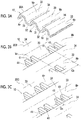
- FIG. 3A is a view illustrating the shape of the upstream region 30A of the gas flow passage-forming member 10.
- FIG. 3B is a view illustrating the shape of the midstream region 30B of the gas flow passage-forming member 10.
- FIG. 3C is a view illustrating the shape of the downstream region 30C of the gas flow passage-forming member 10.
- the gas flow passage-forming member 10 has a plurality of groove portions (recessed portions) 31 extending in the airflow direction and arranged parallel to one another.
- the groove portions 31 are provided on a surface of the gas flow passage-forming member 10, which faces the MEGA 12.
- Ridge portions (protruding portions) 32 protruding toward the MEGA 12 are provided between the groove portions 31.
- the back side of each ridge portion 32 is a groove portion (recessed portion) 33
- the back side of each groove portion 31 is a ridge portion (protruding portion) 34 protruding toward the separator 13.
- the ridge portions 32 of the gas flow passage-forming member 10 are brought into contact with the MEGA 12, and the ridge portions 34 of the gas flow passage-forming member 10 are brought into contact with the separator 13.
- the cell 11 is provided with gas flow passages Ar, through which the air flows, and drainage passages Wr.
- the gas flow passages Ar are formed on a surface of the MEGA 12 by the groove portions 31 of the gas flow passage-forming member 10, which are provided on the MEGA 12-side.
- the drainage passages Wr are formed on a surface of the separator 13 by the groove portions 33 of the gas flow passage-forming member 10, which are provided on the separator 13-side.
- the gas flow passage-forming member 10 is provided with communication holes 41 that provide communication between the front side and the back side of the gas flow passage-forming member 10.
- the communication holes 41 are provided in the midstream region 30B and a further downstream region of the gas flow passage-forming member 10, excluding the upstream region 30A.
- the communication holes 41 are provided in the midstream region 30B and the downstream region 30C.
- the communication holes 41 are provided in pairs. A distance Gc between a pair of the communication holes 41 and an adjacent pair of the communication holes 41 in the downstream region 30C is shorter than a distance Gb between a pair of the communication holes 41 and an adjacent pair of the communication holes 41 in the midstream region 30B.
- the number of the communication holes 41 per unit area is larger in the downstream region 30C than in the midstream region 30B.
- FIG. 4 is a perspective view illustrating a region of the gas flow passage-forming member 10, where the communication holes 41 are provided.
- FIG. 5 is a view schematically illustrating the region of the gas flow passage-forming member 10, where the communication holes 41 are provided.
- FIG. 5 is a sectional view taken in the width direction of the cell 11.
- recesses 42 are formed in the ridge portions 32 provided between the groove portions 31 and protruding toward the MEGA 12.
- the communication holes 41 in the form of a slit are provided between bottom portions of the recesses 42 and bottom portions of the groove portions 33 that are provided on the separator 13-side.
- the upstream region 30A is a non-communication region with no communication holes 41.
- the air electrode A of the cell 11 a space on the MEGA 12-side and a space on the separator 13-side are separated from each other by the gas flow passage-forming member 10 in the upstream region 30A with no communication holes 41.
- the air is supplied to only the MEGA 12-side, and the carried-away amount of vapor of the generated water generated in the MEGA 12 is limited, whereby the moisture amount increases toward a downstream-side end portion of the upstream region 30A and the saturated water vapor pressure is reached (refer to the graph of the moisture amount in FIG. 2C ).
- the range of the upstream region 30A is set to a range in which the oxygen partial pressure (air partial pressure) at the downstream-side end portion of the upstream region 30A does not fall below the oxygen partial pressure (air partial pressure) P at a downstream-side outlet of the gas flow passage-forming member 10 (refer to the graph of the oxygen partial pressure (air partial pressure) in FIG. 2B ).
- the oxygen partial pressure (air partial pressure) temporarily increases and then gradually decreases (refer to the graph of the oxygen partial pressure (air partial pressure) in FIG. 2B ), and the moisture amount in the air temporarily decreases and then gradually increases (refer to the graph of the moisture amount in FIG. 2C ).
- the number of the communication holes 41 is larger than that in the midstream region 30B, and thus migration of the generated water generated on the MEGA 12-side to the separator 13-side is promoted.
- the range of the downstream region 30C is set to a range downstream of a position at which liquid water is generated in the vapor of the generated water in the midstream region 30B and the further downstream region (refer to the graph of the moisture amount in FIG. 2C ).
- the in-plane moisture state of the MEGA 12 significantly varies from an upstream-side region to a downstream-side region. This is one of the factors in the performance deterioration. That is, in the upstream-side region of the MEGA 12, the amount of generated water is small, and thus the MEGA 12 is excessively dried due to the drainage performance of the gas flow passage-forming member 10 and the MEGA 12 easily dries up. On the other hand, in the downstream-side region of the MEGA 12, the generated water is not appropriately drained, and the power generation efficiency decreases due to the generated water adhering to the surface of the MEGA 12.
- the communication holes 41 are provided in the midstream region 30B and the further downstream region in the airflow direction, and the upstream region 30A is a non-communication region.
- the flow of generated water generated in the MEGA 12 during power generation can be controlled in a manner that differs between the upstream region 30A, and the midstream region 30B and the further downstream region.
- the upstream region 30A it is possible to suppress drying-up of the MEGA 12 without hindering the flow of the air.
- the midstream region 30B and the further downstream region it is possible to ensure appropriate generated-water drainage performance. As a result, it is possible to ensure appropriate power generation efficiency throughout the entire region of the MEGA 12, thereby increasing the power generation amount.
- a plurality of the communication holes 41 is provided in the midstream region 30B and the downstream region 30C in the airflow direction, and the distance Gc between a pair of the communication holes 41 and an adjacent pair of the communication holes 41 in the downstream region 30C is shorter than the distance Gb between a pair of the communication holes 41 and an adjacent pair of the communication holes 41 in the midstream region 30B.
- the gas flow passage-forming member 10 when used, it is possible to control the state of moisture facing the MEGA 12, thereby maintaining the appropriate moisture retaining state and the appropriate oxygen partial pressure (air partial pressure). Thus, it is possible to appropriately maintain the output from the cell 11 and temperature of the cell 11, while suppressing, for example, drying-up of the MEGA 12 during high-temperature operation.
- the manner for controlling the drainage performance in the communication holes 41 of the gas flow passage-forming member 10 is not limited to adjustment of the number of the communication holes 41.
- the drainage performance may be controlled by adjusting the capillary attraction in the communication holes 41, for example, as illustrated in FIG. 6A and FIG. 6B .
- the drainage performance may be controlled by increasing or decreasing a height H of the recesses 42 for forming the communication holes 41.
- the drainage performance may be controlled by increasing or decreasing a width W of the recesses 42 for forming the communication holes 41.
- the width W of the communication hole 41 in the downstream region 30C is set to be smaller than the width W of the communication hole 41 in the midstream region 30B.
- the capillary action is suppressed by increasing a distance G between the communication holes 41 in a region where the MEGA 12 is easily dried and the capillary action is improved by decreasing the distance G between the communication holes 41 in a region where the MEGA 12 is not easily dried.
- the gas flow passage-forming member is a gas flow passage-forming member disposed between an MEGA and a separator that constitute a cell for a fuel cell and used to form a gas flow passage.
- the gas flow passage-forming member has a corrugated shape, that is, the gas flow passage-forming member has recessed portions and protruding portions on the front side and the back side. The recessed portions serve as gas flow passages.
- the gas flow passage-forming member has communication holes, which provide communication between the front side and the back side of the gas flow passage-forming member. The communication holes are provided in a region including a midstream region and a downstream region, that is, a region downstream of an upstream region in the gas flow direction.
- the upstream region is a non-communication region with no communication holes.
- the distance between the communication holes provided in the downstream region which is continuous with the midstream region may be shorter than the distance between the communication holes in the midstream region.
- the drainage performance in the downstream region is higher than that in the midstream region. As a result, it is possible to suppress the variations in the moisture amount in the entire region, thereby improving the power generation performance.
- the gas flow passage-forming member may have a plurality of communication passages having different heights from the MEGA.
- the gas flow passage-forming member may have a plurality of communication passages having different widths.
- a cell for a fuel cell provided with a gas flow passage-forming member includes a separator, an MEGA, and the gas flow passage-forming member provided between the separator and the MEGA.
- the gas flow passage-forming member has protruding portions protruding toward the MEGA and brought into contact with the MEGA, and recessed portions provided continuously with the protruding portions.
- the gas flow passage-forming member forms first flow passages, which are clearances between the recessed portions and the MEGA, and second passages, which are clearances between the protruding portions and the separator.
- the gas supplied from an inlet flows through the first flow passages and is discharged through an outlet, whereby electric power is generated.
- a plurality of holes providing communication between the first flow passages and the second flow passages is provided in a region downstream of the upstream region.
- the moisture in the first flow passages can migrate to the second flow passages with the use of the hole.
- the holes may be provided so as to increase the partial pressure of the gas which decreases toward the downstream side in the upstream region.
- the partial pressure of the gas which decreases in the upstream region is increased in the midstream region.
- the holes may be provided such that the partial pressure of the gas at a downstream-side end portion of the upstream region does not fall below the partial pressure of the gas at the outlet.
- the partial pressure of the gas which has decreased in the upstream region does not fall below the partial pressure of the gas at the outlet.
- a plurality of holes providing communication between the first flow passages and the second flow passages may be provided, and the distance between the holes may be set to be shorter than that in the midstream region.
- the drainage efficiency improves.
Abstract
Description
- The invention relates to a gas flow passage-forming member, and relates also to a cell for a fuel cell.
- As a cell for a fuel cell, there is a known cell including a membrane electrode and gas diffusion layer assembly (hereinafter, referred to as "MEGA" where appropriate), separators, and gas flow passage-forming members disposed between the MEGA and the separators (refer to, for example,
Japanese Patent Application Publication No. 2011-44399 JP 2011-44399 A - In the cell including the gas flow passage-forming members, generated water generated in the MEGA can be appropriately drained. However, during a high-temperature operation of the fuel cell, the generated water is excessively drained and thus the MEGA easily dries up.
- In view of this, in the cell having the above-described configuration, a flat plate portion provided in the gas flow passage-forming member is brought into close contact with the MEGA, on the upstream side in the airflow direction, where the MEGA easily dries up. However, when the flat plate portion is brought into close contact with the MEGA as described above, the power generation efficiency at a region, where the flat plate portion is in close contact with the MEGA, decreases and thus the amount of electric power generated by the cell decreases.
- The invention provides a gas flow passage-forming member and a cell for a fuel cell, the gas flow passage-forming member and the cell being configured to suppress drying-up of an MEGA without decreasing the power generation efficiency, and configured to ensure appropriate drainage performance.
- A first aspect of the invention relates to a gas flow passage-forming member that is disposed between a membrane electrode and gas diffusion layer assembly (MEGA) and a separator that constitute a cell for a fuel cell, and that is configured to form a gas flow passage. The gas flow passage-forming member has a corrugated shape such that recessed portions and protruding portions are provided on each of a front side and a back side of the gas flow passage-forming member. The recessed portions on the front side each serve as the gas flow passage. The gas flow passage-forming member has a communication hole providing communication between the front side of the gas flow passage-forming member and the back side of the gas flow passage-forming member, and the communication hole is provided in a region downstream of an upstream region in a gas flow direction, the region including a midstream region and a downstream region. The upstream region is a non-communication region with no communication hole.
- In the gas flow passage-forming member, the communication hole is provided in the midstream region and the further downstream region in the gas flow direction, and the upstream region is a non-communication region. Thus, the flow of generated water generated in the MEGA during power generation can be controlled in a manner that differs between the upstream region, and the midstream region and the further downstream region. Thus, in the upstream region that is the non-communication region with no communication hole, it is possible to suppress drying-up of the MEGA without hindering the flow of the gas. In the midstream region and the further downstream region, it is possible to ensure appropriate generated-water drainage performance. As a result, it is possible to ensure appropriate power generation efficiency throughout the entire region of the MEGA, thereby increasing the power generation amount.
- With the gas flow passage-forming member according to the first aspect of the invention, it is possible to suppress drying-up of the MEGA without decreasing the power generation efficiency, and to ensure appropriate drainage performance.
- A second aspect of the invention relates to a cell for a fuel cell including an MEGA, a separator, and the gas flow passage-forming member according to the first aspect, which is disposed between the MEGA and the separator.
- Features, advantages, and technical and industrial significance of exemplary embodiments of the invention will be described below with reference to the accompanying drawings, in which like numerals denote like elements, and wherein:
-
FIG. 1 is a sectional view schematically illustrating a cell for a fuel cell stack; -
FIG. 2A is a front view schematically illustrating a gas flow passage-forming member according to an example embodiment; -
FIG. 2B is a graph indicating an oxygen partial pressure (air partial pressure) in each of regions of the gas flow passage-forming member; -
FIG. 2C is a graph indicating a moisture amount in each of the regions of the gas flow passage-forming member; -
FIG. 3A is a view illustrating the shape of an upstream region of the gas flow passage-forming member; -
FIG. 3B is a view illustrating the shape of a midstream region of the gas flow passage-forming member; -
FIG. 3C is a view illustrating the shape of a downstream region of the gas flow passage-forming member; -
FIG. 4 is a perspective view illustrating a region of the gas flow passage-forming member, where communication holes are provided; -
FIG. 5 is a view schematically illustrating the region of the gas flow passage-forming member, where the communication holes are provided,FIG. 5 being a sectional view taken in the width direction of a cell; -
FIG. 6A is a view schematically illustrating a method for adjusting the capillary attraction in the communication holes,FIG. 6A being a sectional view taken in the gas flow direction; -
FIG. 6B is a view schematically illustrating a method for adjusting the capillary attraction in the communication holes,FIG. 6B being a sectional view taken in the gas flow direction; and -
FIG. 6C is a view schematically illustrating a method for adjusting the capillary attraction in the communication holes,FIG. 6C being a sectional view taken in the gas flow direction. - Hereinafter, a gas flow passage-forming member according to an embodiment of the invention will be described with reference to the accompanying drawings.
FIG. 1 is a sectional view schematically illustrating a cell for a fuel cell stack. - As illustrated in
FIG. 1 , gas flow passage-formingmembers 10 according to the present embodiment are provided in acell 11 for a fuel cell stack. Thecell 11 includes a membrane electrode and gas diffusion layer assembly (hereinafter, referred to as "MEGA") 12 andseparators 13. One of theseparators 13 is provided on one side of the MEGA 12, and the other one of theseparators 13 is provided on the other side of the MEGA 12. In theMEGA 12, a catalyst layer and a diffusion layer are provided on each of two sides of a membrane electrode assembly (MEA). The gas flow passage-formingmember 10 is a member for forming a three-dimensional fine mesh flow passage (referred also to as "3D fine mesh flow passage"). The gas flow passage-formingmember 10 is disposed between the MEGA 12 and eachseparator 13. The gas flow passage-formingmember 10 is made of, for example, ferritic stainless steel (SUS), a titanium alloy, carbon, a gold-plated titanium alloy, or a gold alloy. The gas flow passage-formingmember 10 may be made of a porous material. - In the
cell 11, one of the gas flow passage-formingmembers 10 forms an air electrode A on one side of theMEGA 12, the other one of the gas flow passage-formingmembers 10 forms a fuel electrode B on the other side of theMEGA 12. A pair of theseparators 13 is provided such that the air electrode A and the fuel electrode B are sandwiched by theseparators 13. Air serving as oxidation gas is supplied to the air electrode A of thecell 11, and hydrogen gas serving as fuel gas is supplied to the fuel electrode B of thecell 11. Then, an electrochemical reaction between air and hydrogen occurs in theMEGA 12 of thecell 11, whereby electric power is generated. -
FIG. 2A is a front view schematically illustrating the gas flow passage-formingmember 10 according to the present embodiment.FIG. 2B is a graph indicating an oxygen partial pressure (air partial pressure) in each of regions of the gas flow passage-formingmember 10.FIG. 2C is a graph indicating a moisture amount in each of the regions of the gas flow passage-formingmember 10. - As illustrated in
FIG. 2A , thecell 11 has a manifold 21 A at one end, and a manifold 21B at the other end. Air is supplied to the air electrode A of thecell 11 through anair inlet 22A of the manifold 21A, and is discharged through anair outlet 22B of the manifold 21B. Thus, in the air electrode A, the air flows from the manifold 21 A toward the manifold 21B (in the direction of an arrow X inFIG. 2A ). The gas flow passage-formingmember 10 provided at the air electrode A is divided into a plurality of regions in the airflow direction. Specifically, an upstream portion of the gas flow passage-formingmember 10 in the airflow direction is anupstream region 30A, a midstream portion thereof in the airflow direction is amidstream region 30B, and a downstream portion thereof in the airflow direction is adownstream region 30C. -
FIG. 3A is a view illustrating the shape of theupstream region 30A of the gas flow passage-formingmember 10.FIG. 3B is a view illustrating the shape of themidstream region 30B of the gas flow passage-formingmember 10.FIG. 3C is a view illustrating the shape of thedownstream region 30C of the gas flow passage-formingmember 10. - As illustrated in
FIG. 3A to FIG. 3C , the gas flow passage-formingmember 10 has a plurality of groove portions (recessed portions) 31 extending in the airflow direction and arranged parallel to one another. Thegroove portions 31 are provided on a surface of the gas flow passage-formingmember 10, which faces theMEGA 12. Ridge portions (protruding portions) 32 protruding toward theMEGA 12 are provided between thegroove portions 31. In the gas flow passage-formingmember 10, the back side of eachridge portion 32 is a groove portion (recessed portion) 33, and the back side of eachgroove portion 31 is a ridge portion (protruding portion) 34 protruding toward theseparator 13. Theridge portions 32 of the gas flow passage-formingmember 10 are brought into contact with theMEGA 12, and theridge portions 34 of the gas flow passage-formingmember 10 are brought into contact with theseparator 13. Thus, thecell 11 is provided with gas flow passages Ar, through which the air flows, and drainage passages Wr. The gas flow passages Ar are formed on a surface of theMEGA 12 by thegroove portions 31 of the gas flow passage-formingmember 10, which are provided on the MEGA 12-side. The drainage passages Wr are formed on a surface of theseparator 13 by thegroove portions 33 of the gas flow passage-formingmember 10, which are provided on the separator 13-side. - As illustrated in
FIG. 3B and FIG. 3C , the gas flow passage-formingmember 10 is provided withcommunication holes 41 that provide communication between the front side and the back side of the gas flow passage-formingmember 10. The communication holes 41 are provided in themidstream region 30B and a further downstream region of the gas flow passage-formingmember 10, excluding theupstream region 30A. In other words, the communication holes 41 are provided in themidstream region 30B and thedownstream region 30C. The communication holes 41 are provided in pairs. A distance Gc between a pair of the communication holes 41 and an adjacent pair of the communication holes 41 in thedownstream region 30C is shorter than a distance Gb between a pair of the communication holes 41 and an adjacent pair of the communication holes 41 in themidstream region 30B. Thus, the number of the communication holes 41 per unit area is larger in thedownstream region 30C than in themidstream region 30B. -
FIG. 4 is a perspective view illustrating a region of the gas flow passage-formingmember 10, where the communication holes 41 are provided.FIG. 5 is a view schematically illustrating the region of the gas flow passage-formingmember 10, where the communication holes 41 are provided.FIG. 5 is a sectional view taken in the width direction of thecell 11. - As illustrated in
FIG. 4 andFIG. 5 , in themidstream region 30B and thedownstream region 30C of the gas flow passage-formingmember 10, recesses 42 are formed in theridge portions 32 provided between thegroove portions 31 and protruding toward theMEGA 12. Thus, the communication holes 41 in the form of a slit are provided between bottom portions of therecesses 42 and bottom portions of thegroove portions 33 that are provided on the separator 13-side. - In the gas flow passage-forming
member 10 having the communication holes 41, generated water SW generated in theMEGA 12 during power generation is drawn up by capillary action in the communication holes 41 in the form of a silt, is then introduced into the drainage passages Wr formed by thegroove portions 33 provided on the separator 13-side, and is finally drained. - In the gas flow passage-forming
member 10 having the above-described configuration, theupstream region 30A is a non-communication region with no communication holes 41. Thus, in the air electrode A of thecell 11, a space on the MEGA 12-side and a space on the separator 13-side are separated from each other by the gas flow passage-formingmember 10 in theupstream region 30A with no communication holes 41. Thus, in theupstream region 30A, the air is supplied to only the MEGA 12-side, and the carried-away amount of vapor of the generated water generated in theMEGA 12 is limited, whereby the moisture amount increases toward a downstream-side end portion of theupstream region 30A and the saturated water vapor pressure is reached (refer to the graph of the moisture amount inFIG. 2C ). The range of theupstream region 30A is set to a range in which the oxygen partial pressure (air partial pressure) at the downstream-side end portion of theupstream region 30A does not fall below the oxygen partial pressure (air partial pressure) P at a downstream-side outlet of the gas flow passage-forming member 10 (refer to the graph of the oxygen partial pressure (air partial pressure) inFIG. 2B ). - In the
midstream region 30B and the further downstream region that have the communication holes 41, due to the drainage function of the communication holes 41, the oxygen partial pressure (air partial pressure) temporarily increases and then gradually decreases (refer to the graph of the oxygen partial pressure (air partial pressure) inFIG. 2B ), and the moisture amount in the air temporarily decreases and then gradually increases (refer to the graph of the moisture amount inFIG. 2C ). - In the
downstream region 30C, the number of the communication holes 41 is larger than that in themidstream region 30B, and thus migration of the generated water generated on the MEGA 12-side to the separator 13-side is promoted. The range of thedownstream region 30C is set to a range downstream of a position at which liquid water is generated in the vapor of the generated water in themidstream region 30B and the further downstream region (refer to the graph of the moisture amount inFIG. 2C ). - If a gas flow passage-forming member having the communication holes 41 that are evenly provided throughout the entire region from the
upstream region 30A to thedownstream region 30C is used as the gas flow passage-formingmember 10, the in-plane moisture state of theMEGA 12 significantly varies from an upstream-side region to a downstream-side region. This is one of the factors in the performance deterioration. That is, in the upstream-side region of theMEGA 12, the amount of generated water is small, and thus theMEGA 12 is excessively dried due to the drainage performance of the gas flow passage-formingmember 10 and theMEGA 12 easily dries up. On the other hand, in the downstream-side region of theMEGA 12, the generated water is not appropriately drained, and the power generation efficiency decreases due to the generated water adhering to the surface of theMEGA 12. - In contrast to this, according to the present embodiment, the communication holes 41 are provided in the
midstream region 30B and the further downstream region in the airflow direction, and theupstream region 30A is a non-communication region. Thus, the flow of generated water generated in theMEGA 12 during power generation can be controlled in a manner that differs between theupstream region 30A, and themidstream region 30B and the further downstream region. Thus, in theupstream region 30A, it is possible to suppress drying-up of theMEGA 12 without hindering the flow of the air. In themidstream region 30B and the further downstream region, it is possible to ensure appropriate generated-water drainage performance. As a result, it is possible to ensure appropriate power generation efficiency throughout the entire region of theMEGA 12, thereby increasing the power generation amount. - More specifically, a plurality of the communication holes 41 is provided in the
midstream region 30B and thedownstream region 30C in the airflow direction, and the distance Gc between a pair of the communication holes 41 and an adjacent pair of the communication holes 41 in thedownstream region 30C is shorter than the distance Gb between a pair of the communication holes 41 and an adjacent pair of the communication holes 41 in themidstream region 30B. Thus, in themidstream region 30B and thedownstream region 30C in which flooding is likely to occur, appropriate generated-water drainage performance is ensured by the communication holes 41. Further, the drainage performance in thedownstream region 30C is higher than that in themidstream region 30B. As a result, it is possible to further suppress the variations in the moisture amount in the entire region of theMEGA 12, thereby improving the power generation performance. - As described above, when the gas flow passage-forming
member 10 according to the present embodiment is used, it is possible to control the state of moisture facing theMEGA 12, thereby maintaining the appropriate moisture retaining state and the appropriate oxygen partial pressure (air partial pressure). Thus, it is possible to appropriately maintain the output from thecell 11 and temperature of thecell 11, while suppressing, for example, drying-up of theMEGA 12 during high-temperature operation. - Note that, the manner for controlling the drainage performance in the communication holes 41 of the gas flow passage-forming
member 10 is not limited to adjustment of the number of the communication holes 41. - The drainage performance may be controlled by adjusting the capillary attraction in the communication holes 41, for example, as illustrated in
FIG. 6A and FIG. 6B . As illustrated inFIG. 6A , the drainage performance may be controlled by increasing or decreasing a height H of therecesses 42 for forming the communication holes 41. As illustrated inFIG. 6B , the drainage performance may be controlled by increasing or decreasing a width W of therecesses 42 for forming the communication holes 41. For example, the width W of thecommunication hole 41 in thedownstream region 30C is set to be smaller than the width W of thecommunication hole 41 in themidstream region 30B. As illustrated inFIG. 6C , for example, in themidstream region 30B and thedownstream region 30C, preferably, the capillary action is suppressed by increasing a distance G between the communication holes 41 in a region where theMEGA 12 is easily dried and the capillary action is improved by decreasing the distance G between the communication holes 41 in a region where theMEGA 12 is not easily dried. - In the foregoing embodiment, the air electrode A in which the air flows has been described. However, it is needless to say that the invention is applicable to the fuel electrode B in which hydrogen flows.
- The description of the foregoing embodiment will be summarized as follows. The gas flow passage-forming member is a gas flow passage-forming member disposed between an MEGA and a separator that constitute a cell for a fuel cell and used to form a gas flow passage. The gas flow passage-forming member has a corrugated shape, that is, the gas flow passage-forming member has recessed portions and protruding portions on the front side and the back side. The recessed portions serve as gas flow passages. The gas flow passage-forming member has communication holes, which provide communication between the front side and the back side of the gas flow passage-forming member. The communication holes are provided in a region including a midstream region and a downstream region, that is, a region downstream of an upstream region in the gas flow direction. The upstream region is a non-communication region with no communication holes.
- The distance between the communication holes provided in the downstream region which is continuous with the midstream region may be shorter than the distance between the communication holes in the midstream region.
- With this configuration, the drainage performance in the downstream region is higher than that in the midstream region. As a result, it is possible to suppress the variations in the moisture amount in the entire region, thereby improving the power generation performance.
- The gas flow passage-forming member may have a plurality of communication passages having different heights from the MEGA.
- With this configuration, in the midstream region and the downstream region, it is possible to control the drainage performance by adjusting the capillary action.
- The gas flow passage-forming member may have a plurality of communication passages having different widths.
- With this configuration, in the midstream region and the downstream region, it is possible to control the drainage performance by adjusting the capillary action.
- A cell for a fuel cell provided with a gas flow passage-forming member includes a separator, an MEGA, and the gas flow passage-forming member provided between the separator and the MEGA. The gas flow passage-forming member has protruding portions protruding toward the MEGA and brought into contact with the MEGA, and recessed portions provided continuously with the protruding portions. The gas flow passage-forming member forms first flow passages, which are clearances between the recessed portions and the MEGA, and second passages, which are clearances between the protruding portions and the separator. In the cell for a fuel cell, the gas supplied from an inlet flows through the first flow passages and is discharged through an outlet, whereby electric power is generated. In the gas flow passage-forming member, in order to decrease the moisture amount which increases toward the downstream side in the upstream region of the first flow passages, a plurality of holes providing communication between the first flow passages and the second flow passages is provided in a region downstream of the upstream region.
- With the cell for a fuel cell, the moisture in the first flow passages can migrate to the second flow passages with the use of the hole. Thus, it is possible to appropriately discharge the generated water generated in the MEGA, thereby suppressing deterioration of the power generation efficiency.
- The holes may be provided so as to increase the partial pressure of the gas which decreases toward the downstream side in the upstream region.
- Thus, the partial pressure of the gas which decreases in the upstream region is increased in the midstream region. Thus, it is possible to suppress deterioration of the power generation efficiency.
- The holes may be provided such that the partial pressure of the gas at a downstream-side end portion of the upstream region does not fall below the partial pressure of the gas at the outlet.
- Thus, even at the downstream-side end portion of the upstream region, the partial pressure of the gas which has decreased in the upstream region does not fall below the partial pressure of the gas at the outlet. Thus, it is possible to suppress deterioration of the power generation efficiency.
- In the downstream region which is continuous with the midstream region, a plurality of holes providing communication between the first flow passages and the second flow passages may be provided, and the distance between the holes may be set to be shorter than that in the midstream region.
- Thus, the drainage efficiency improves. Thus, it is possible to suppress deterioration of the power generation efficiency even when the saturation water vapor pressure is reached and liquid water is generated in the downstream region.
Claims (5)
- A gas flow passage-forming member (10) disposed between a membrane electrode and gas diffusion layer assembly (12) and a separator (13) that constitute a cell (11) for a fuel cell, the gas flow passage-forming member (10) being configured to form a gas flow passage,
wherein the gas flow passage-forming member (10) has a corrugated shape such that recessed portions and protruding portions are provided on each of a front side and a back side of the gas flow passage-forming member (10),
wherein the recessed portions (31) on the front side each serve as the gas flow passage,
wherein the gas flow passage-forming member (10) has a communication hole (41) providing communication between the front side of the gas flow passage-forming member (10) and the back side of the gas flow passage-forming member (10), and the communication hole (41) is provided in a region downstream of an upstream region (30A) in a gas flow direction, the region including a midstream region (30B) and a downstream region (30C), and
wherein the upstream region (30A) is a non-communication region with no communication hole (41). - The gas flow passage-forming member according to claim 1, wherein the gas flow passage-forming member (10) has a plurality of the communication holes (41).
- The gas flow passage-forming member according to claim 2,
wherein a plurality of the communication holes (41) is provided in each of the midstream region (30B) and the downstream region (30C), and
wherein a distance (Gc) between the communication holes (41) adjacent to each other in the downstream region (30C) is shorter than a distance (Gb) between the communication holes (41) adjacent to each other in the midstream region (30B). - The gas flow passage-forming member according to claim 2 or 3, wherein a width of each of the communication holes (41) in the downstream region (30C) is smaller than a width of each of the communication holes (41) in the midstream region (30B).
- A cell for a fuel cell, the cell comprising:a membrane electrode and gas diffusion layer assembly (12);a separator (13); andthe gas flow passage-forming member according to any one of claims 1 to 4, the gas flow passage-forming member being provided between the membrane electrode and gas diffusion layer assembly (12) and the separator (13).
Applications Claiming Priority (2)
| Application Number | Priority Date | Filing Date | Title |
|---|---|---|---|
| JP2016148922 | 2016-07-28 | ||
| JP2017131797A JP6944123B2 (en) | 2016-07-28 | 2017-07-05 | Gas flow path forming member |
Publications (2)
| Publication Number | Publication Date |
|---|---|
| EP3276722A1 true EP3276722A1 (en) | 2018-01-31 |
| EP3276722B1 EP3276722B1 (en) | 2019-10-16 |
Family
ID=59409279
Family Applications (1)
| Application Number | Title | Priority Date | Filing Date |
|---|---|---|---|
| EP17183337.9A Active EP3276722B1 (en) | 2016-07-28 | 2017-07-26 | Gas flow passage-forming member and cell for fuel cell |
Country Status (2)
| Country | Link |
|---|---|
| US (1) | US10181607B2 (en) |
| EP (1) | EP3276722B1 (en) |
Families Citing this family (2)
| Publication number | Priority date | Publication date | Assignee | Title |
|---|---|---|---|---|
| DE102014210370A1 (en) * | 2014-06-02 | 2015-12-03 | Volkswagen Aktiengesellschaft | Humidifier, plate, device and motor vehicle |
| CN112786914A (en) * | 2021-02-23 | 2021-05-11 | 上海电气集团股份有限公司 | Bipolar plate and fuel cell |
Citations (3)
| Publication number | Priority date | Publication date | Assignee | Title |
|---|---|---|---|---|
| JP2011044399A (en) | 2009-08-24 | 2011-03-03 | Toyota Motor Corp | Fuel cell |
| US20150236368A1 (en) * | 2013-02-28 | 2015-08-20 | Toyota Shatai Kabushiki Kaisha | Gas flow path forming bodies of fuel cell, and fuel cell |
| EP3133685A1 (en) * | 2015-08-21 | 2017-02-22 | Toyota Shatai Kabushiki Kaisha | Gas channel forming plate for fuel cell and fuel cell stack |
Family Cites Families (4)
| Publication number | Priority date | Publication date | Assignee | Title |
|---|---|---|---|---|
| JP5125275B2 (en) * | 2007-02-05 | 2013-01-23 | トヨタ自動車株式会社 | Fuel cell and vehicle equipped with fuel cell |
| JP2009026476A (en) | 2007-07-17 | 2009-02-05 | Toyota Motor Corp | Unit cell of fuel cell |
| JP5648293B2 (en) | 2010-02-12 | 2015-01-07 | トヨタ車体株式会社 | Fuel cell |
| JP6079303B2 (en) | 2013-02-28 | 2017-02-15 | トヨタ車体株式会社 | Gas flow path forming body of fuel cell and fuel cell |
-
2017
- 2017-07-26 US US15/660,085 patent/US10181607B2/en active Active
- 2017-07-26 EP EP17183337.9A patent/EP3276722B1/en active Active
Patent Citations (3)
| Publication number | Priority date | Publication date | Assignee | Title |
|---|---|---|---|---|
| JP2011044399A (en) | 2009-08-24 | 2011-03-03 | Toyota Motor Corp | Fuel cell |
| US20150236368A1 (en) * | 2013-02-28 | 2015-08-20 | Toyota Shatai Kabushiki Kaisha | Gas flow path forming bodies of fuel cell, and fuel cell |
| EP3133685A1 (en) * | 2015-08-21 | 2017-02-22 | Toyota Shatai Kabushiki Kaisha | Gas channel forming plate for fuel cell and fuel cell stack |
Also Published As
| Publication number | Publication date |
|---|---|
| US20180034079A1 (en) | 2018-02-01 |
| EP3276722B1 (en) | 2019-10-16 |
| US10181607B2 (en) | 2019-01-15 |
Similar Documents
| Publication | Publication Date | Title |
|---|---|---|
| US11489175B2 (en) | Fuel cell flow channels and flow fields | |
| CN107810573B (en) | Separator, method of manufacturing the same, and fuel cell stack including the same | |
| US20090011310A1 (en) | Bipolar plate with microgrooves for improved water transport | |
| JP5408263B2 (en) | Fuel cell | |
| US20140162175A1 (en) | Fuel cell and manufacturing method of expanded metal | |
| US9608282B2 (en) | Fuel cell having perforated flow field | |
| EP2963711B1 (en) | Gas flow channel forming body for fuel cell, and fuel cell | |
| JP6079304B2 (en) | Gas flow path forming body of fuel cell and fuel cell | |
| JP6604261B2 (en) | Fuel cell | |
| EP3297078B1 (en) | Separating plate, method for manufacturing same, and fuel cell stack comprising same | |
| EP3276722B1 (en) | Gas flow passage-forming member and cell for fuel cell | |
| JP2005174648A (en) | Fuel cell | |
| KR101075518B1 (en) | Bipolar plate with nano and micro structures | |
| JP2006147466A (en) | Fuel cell and separator for fuel cell | |
| JP5912579B2 (en) | Fuel cell | |
| JP4939103B2 (en) | Fuel cell | |
| JP6117736B2 (en) | Fuel cell | |
| JP5749703B2 (en) | Fuel cell stack | |
| JP6944123B2 (en) | Gas flow path forming member | |
| JP7222166B2 (en) | fuel cell stack | |
| JP2009277557A (en) | Fuel cell | |
| JP6403099B2 (en) | Fuel cell module | |
| JP5577156B2 (en) | Fuel cell | |
| JP4736453B2 (en) | Fuel cell separator | |
| CN112771700B (en) | Fluid guide channel and fuel cell provided with same |
Legal Events
| Date | Code | Title | Description |
|---|---|---|---|
| PUAI | Public reference made under article 153(3) epc to a published international application that has entered the european phase |
Free format text: ORIGINAL CODE: 0009012 |
|
| STAA | Information on the status of an ep patent application or granted ep patent |
Free format text: STATUS: REQUEST FOR EXAMINATION WAS MADE |
|
| 17P | Request for examination filed |
Effective date: 20170726 |
|
| AK | Designated contracting states |
Kind code of ref document: A1 Designated state(s): AL AT BE BG CH CY CZ DE DK EE ES FI FR GB GR HR HU IE IS IT LI LT LU LV MC MK MT NL NO PL PT RO RS SE SI SK SM TR |
|
| AX | Request for extension of the european patent |
Extension state: BA ME |
|
| GRAP | Despatch of communication of intention to grant a patent |
Free format text: ORIGINAL CODE: EPIDOSNIGR1 |
|
| STAA | Information on the status of an ep patent application or granted ep patent |
Free format text: STATUS: GRANT OF PATENT IS INTENDED |
|
| RIC1 | Information provided on ipc code assigned before grant |
Ipc: H01M 8/04119 20160101ALI20190118BHEP Ipc: H01M 8/0258 20160101AFI20190118BHEP Ipc: H01M 8/0254 20160101ALI20190118BHEP Ipc: H01M 8/1018 20160101ALN20190118BHEP Ipc: H01M 8/0206 20160101ALN20190118BHEP |
|
| INTG | Intention to grant announced |
Effective date: 20190214 |
|
| RAP1 | Party data changed (applicant data changed or rights of an application transferred) |
Owner name: TOYOTA JIDOSHA KABUSHIKI KAISHA Owner name: TOYOTA SHATAI KABUSHIKI KAISHA |
|
| RIN1 | Information on inventor provided before grant (corrected) |
Inventor name: KAWAJIRI, KOUSUKE Inventor name: SHIBATA, KAZUNORI Inventor name: KANIE, TAKAMASA Inventor name: NAKAJI, HIROYA Inventor name: SHINOZAKI, YOSHINORI Inventor name: OKABE, HIROKI Inventor name: FUTAMI, SATOSHI |
|
| GRAS | Grant fee paid |
Free format text: ORIGINAL CODE: EPIDOSNIGR3 |
|
| GRAA | (expected) grant |
Free format text: ORIGINAL CODE: 0009210 |
|
| STAA | Information on the status of an ep patent application or granted ep patent |
Free format text: STATUS: THE PATENT HAS BEEN GRANTED |
|
| RIN1 | Information on inventor provided before grant (corrected) |
Inventor name: NAKAJI, HIROYA Inventor name: KANIE, TAKAMASA Inventor name: SHINOZAKI, YOSHINORI Inventor name: FUTAMI, SATOSHI Inventor name: SHIBATA, KAZUNORI Inventor name: KAWAJIRI, KOUSUKE Inventor name: OKABE, HIROKI |
|
| AK | Designated contracting states |
Kind code of ref document: B1 Designated state(s): AL AT BE BG CH CY CZ DE DK EE ES FI FR GB GR HR HU IE IS IT LI LT LU LV MC MK MT NL NO PL PT RO RS SE SI SK SM TR |
|
| REG | Reference to a national code |
Ref country code: GB Ref legal event code: FG4D |
|
| REG | Reference to a national code |
Ref country code: CH Ref legal event code: EP |
|
| REG | Reference to a national code |
Ref country code: DE Ref legal event code: R096 Ref document number: 602017007807 Country of ref document: DE |
|
| REG | Reference to a national code |
Ref country code: IE Ref legal event code: FG4D |
|
| REG | Reference to a national code |
Ref country code: AT Ref legal event code: REF Ref document number: 1192175 Country of ref document: AT Kind code of ref document: T Effective date: 20191115 |
|
| REG | Reference to a national code |
Ref country code: NL Ref legal event code: MP Effective date: 20191016 |
|
| REG | Reference to a national code |
Ref country code: LT Ref legal event code: MG4D |
|
| REG | Reference to a national code |
Ref country code: AT Ref legal event code: MK05 Ref document number: 1192175 Country of ref document: AT Kind code of ref document: T Effective date: 20191016 |
|
| PG25 | Lapsed in a contracting state [announced via postgrant information from national office to epo] |
Ref country code: PT Free format text: LAPSE BECAUSE OF FAILURE TO SUBMIT A TRANSLATION OF THE DESCRIPTION OR TO PAY THE FEE WITHIN THE PRESCRIBED TIME-LIMIT Effective date: 20200217 Ref country code: FI Free format text: LAPSE BECAUSE OF FAILURE TO SUBMIT A TRANSLATION OF THE DESCRIPTION OR TO PAY THE FEE WITHIN THE PRESCRIBED TIME-LIMIT Effective date: 20191016 Ref country code: GR Free format text: LAPSE BECAUSE OF FAILURE TO SUBMIT A TRANSLATION OF THE DESCRIPTION OR TO PAY THE FEE WITHIN THE PRESCRIBED TIME-LIMIT Effective date: 20200117 Ref country code: PL Free format text: LAPSE BECAUSE OF FAILURE TO SUBMIT A TRANSLATION OF THE DESCRIPTION OR TO PAY THE FEE WITHIN THE PRESCRIBED TIME-LIMIT Effective date: 20191016 Ref country code: NO Free format text: LAPSE BECAUSE OF FAILURE TO SUBMIT A TRANSLATION OF THE DESCRIPTION OR TO PAY THE FEE WITHIN THE PRESCRIBED TIME-LIMIT Effective date: 20200116 Ref country code: NL Free format text: LAPSE BECAUSE OF FAILURE TO SUBMIT A TRANSLATION OF THE DESCRIPTION OR TO PAY THE FEE WITHIN THE PRESCRIBED TIME-LIMIT Effective date: 20191016 Ref country code: AT Free format text: LAPSE BECAUSE OF FAILURE TO SUBMIT A TRANSLATION OF THE DESCRIPTION OR TO PAY THE FEE WITHIN THE PRESCRIBED TIME-LIMIT Effective date: 20191016 Ref country code: LV Free format text: LAPSE BECAUSE OF FAILURE TO SUBMIT A TRANSLATION OF THE DESCRIPTION OR TO PAY THE FEE WITHIN THE PRESCRIBED TIME-LIMIT Effective date: 20191016 Ref country code: SE Free format text: LAPSE BECAUSE OF FAILURE TO SUBMIT A TRANSLATION OF THE DESCRIPTION OR TO PAY THE FEE WITHIN THE PRESCRIBED TIME-LIMIT Effective date: 20191016 Ref country code: LT Free format text: LAPSE BECAUSE OF FAILURE TO SUBMIT A TRANSLATION OF THE DESCRIPTION OR TO PAY THE FEE WITHIN THE PRESCRIBED TIME-LIMIT Effective date: 20191016 Ref country code: BG Free format text: LAPSE BECAUSE OF FAILURE TO SUBMIT A TRANSLATION OF THE DESCRIPTION OR TO PAY THE FEE WITHIN THE PRESCRIBED TIME-LIMIT Effective date: 20200116 |
|
| PG25 | Lapsed in a contracting state [announced via postgrant information from national office to epo] |
Ref country code: IS Free format text: LAPSE BECAUSE OF FAILURE TO SUBMIT A TRANSLATION OF THE DESCRIPTION OR TO PAY THE FEE WITHIN THE PRESCRIBED TIME-LIMIT Effective date: 20200224 Ref country code: HR Free format text: LAPSE BECAUSE OF FAILURE TO SUBMIT A TRANSLATION OF THE DESCRIPTION OR TO PAY THE FEE WITHIN THE PRESCRIBED TIME-LIMIT Effective date: 20191016 Ref country code: RS Free format text: LAPSE BECAUSE OF FAILURE TO SUBMIT A TRANSLATION OF THE DESCRIPTION OR TO PAY THE FEE WITHIN THE PRESCRIBED TIME-LIMIT Effective date: 20191016 |
|
| PG25 | Lapsed in a contracting state [announced via postgrant information from national office to epo] |
Ref country code: AL Free format text: LAPSE BECAUSE OF FAILURE TO SUBMIT A TRANSLATION OF THE DESCRIPTION OR TO PAY THE FEE WITHIN THE PRESCRIBED TIME-LIMIT Effective date: 20191016 |
|
| REG | Reference to a national code |
Ref country code: DE Ref legal event code: R097 Ref document number: 602017007807 Country of ref document: DE |
|
| PG2D | Information on lapse in contracting state deleted |
Ref country code: IS |
|
| PG25 | Lapsed in a contracting state [announced via postgrant information from national office to epo] |
Ref country code: EE Free format text: LAPSE BECAUSE OF FAILURE TO SUBMIT A TRANSLATION OF THE DESCRIPTION OR TO PAY THE FEE WITHIN THE PRESCRIBED TIME-LIMIT Effective date: 20191016 Ref country code: DK Free format text: LAPSE BECAUSE OF FAILURE TO SUBMIT A TRANSLATION OF THE DESCRIPTION OR TO PAY THE FEE WITHIN THE PRESCRIBED TIME-LIMIT Effective date: 20191016 Ref country code: CZ Free format text: LAPSE BECAUSE OF FAILURE TO SUBMIT A TRANSLATION OF THE DESCRIPTION OR TO PAY THE FEE WITHIN THE PRESCRIBED TIME-LIMIT Effective date: 20191016 Ref country code: RO Free format text: LAPSE BECAUSE OF FAILURE TO SUBMIT A TRANSLATION OF THE DESCRIPTION OR TO PAY THE FEE WITHIN THE PRESCRIBED TIME-LIMIT Effective date: 20191016 Ref country code: ES Free format text: LAPSE BECAUSE OF FAILURE TO SUBMIT A TRANSLATION OF THE DESCRIPTION OR TO PAY THE FEE WITHIN THE PRESCRIBED TIME-LIMIT Effective date: 20191016 Ref country code: IS Free format text: LAPSE BECAUSE OF FAILURE TO SUBMIT A TRANSLATION OF THE DESCRIPTION OR TO PAY THE FEE WITHIN THE PRESCRIBED TIME-LIMIT Effective date: 20200216 |
|
| PLBE | No opposition filed within time limit |
Free format text: ORIGINAL CODE: 0009261 |
|
| STAA | Information on the status of an ep patent application or granted ep patent |
Free format text: STATUS: NO OPPOSITION FILED WITHIN TIME LIMIT |
|
| PG25 | Lapsed in a contracting state [announced via postgrant information from national office to epo] |
Ref country code: SM Free format text: LAPSE BECAUSE OF FAILURE TO SUBMIT A TRANSLATION OF THE DESCRIPTION OR TO PAY THE FEE WITHIN THE PRESCRIBED TIME-LIMIT Effective date: 20191016 Ref country code: IT Free format text: LAPSE BECAUSE OF FAILURE TO SUBMIT A TRANSLATION OF THE DESCRIPTION OR TO PAY THE FEE WITHIN THE PRESCRIBED TIME-LIMIT Effective date: 20191016 Ref country code: SK Free format text: LAPSE BECAUSE OF FAILURE TO SUBMIT A TRANSLATION OF THE DESCRIPTION OR TO PAY THE FEE WITHIN THE PRESCRIBED TIME-LIMIT Effective date: 20191016 |
|
| 26N | No opposition filed |
Effective date: 20200717 |
|
| PG25 | Lapsed in a contracting state [announced via postgrant information from national office to epo] |
Ref country code: SI Free format text: LAPSE BECAUSE OF FAILURE TO SUBMIT A TRANSLATION OF THE DESCRIPTION OR TO PAY THE FEE WITHIN THE PRESCRIBED TIME-LIMIT Effective date: 20191016 |
|
| PG25 | Lapsed in a contracting state [announced via postgrant information from national office to epo] |
Ref country code: MC Free format text: LAPSE BECAUSE OF FAILURE TO SUBMIT A TRANSLATION OF THE DESCRIPTION OR TO PAY THE FEE WITHIN THE PRESCRIBED TIME-LIMIT Effective date: 20191016 |
|
| REG | Reference to a national code |
Ref country code: CH Ref legal event code: PL |
|
| REG | Reference to a national code |
Ref country code: BE Ref legal event code: MM Effective date: 20200731 |
|
| PG25 | Lapsed in a contracting state [announced via postgrant information from national office to epo] |
Ref country code: FR Free format text: LAPSE BECAUSE OF NON-PAYMENT OF DUE FEES Effective date: 20200731 Ref country code: CH Free format text: LAPSE BECAUSE OF NON-PAYMENT OF DUE FEES Effective date: 20200731 Ref country code: LI Free format text: LAPSE BECAUSE OF NON-PAYMENT OF DUE FEES Effective date: 20200731 Ref country code: LU Free format text: LAPSE BECAUSE OF NON-PAYMENT OF DUE FEES Effective date: 20200726 |
|
| PG25 | Lapsed in a contracting state [announced via postgrant information from national office to epo] |
Ref country code: BE Free format text: LAPSE BECAUSE OF NON-PAYMENT OF DUE FEES Effective date: 20200731 |
|
| PG25 | Lapsed in a contracting state [announced via postgrant information from national office to epo] |
Ref country code: IE Free format text: LAPSE BECAUSE OF NON-PAYMENT OF DUE FEES Effective date: 20200726 |
|
| GBPC | Gb: european patent ceased through non-payment of renewal fee |
Effective date: 20210726 |
|
| PG25 | Lapsed in a contracting state [announced via postgrant information from national office to epo] |
Ref country code: GB Free format text: LAPSE BECAUSE OF NON-PAYMENT OF DUE FEES Effective date: 20210726 |
|
| PG25 | Lapsed in a contracting state [announced via postgrant information from national office to epo] |
Ref country code: TR Free format text: LAPSE BECAUSE OF FAILURE TO SUBMIT A TRANSLATION OF THE DESCRIPTION OR TO PAY THE FEE WITHIN THE PRESCRIBED TIME-LIMIT Effective date: 20191016 Ref country code: MT Free format text: LAPSE BECAUSE OF FAILURE TO SUBMIT A TRANSLATION OF THE DESCRIPTION OR TO PAY THE FEE WITHIN THE PRESCRIBED TIME-LIMIT Effective date: 20191016 Ref country code: CY Free format text: LAPSE BECAUSE OF FAILURE TO SUBMIT A TRANSLATION OF THE DESCRIPTION OR TO PAY THE FEE WITHIN THE PRESCRIBED TIME-LIMIT Effective date: 20191016 |
|
| PG25 | Lapsed in a contracting state [announced via postgrant information from national office to epo] |
Ref country code: MK Free format text: LAPSE BECAUSE OF FAILURE TO SUBMIT A TRANSLATION OF THE DESCRIPTION OR TO PAY THE FEE WITHIN THE PRESCRIBED TIME-LIMIT Effective date: 20191016 |
|
| PGFP | Annual fee paid to national office [announced via postgrant information from national office to epo] |
Ref country code: DE Payment date: 20230531 Year of fee payment: 7 |