EP3276700A1 - Elektrochemische zelle - Google Patents
Elektrochemische zelle Download PDFInfo
- Publication number
- EP3276700A1 EP3276700A1 EP16181222.7A EP16181222A EP3276700A1 EP 3276700 A1 EP3276700 A1 EP 3276700A1 EP 16181222 A EP16181222 A EP 16181222A EP 3276700 A1 EP3276700 A1 EP 3276700A1
- Authority
- EP
- European Patent Office
- Prior art keywords
- housing
- composite body
- electrode composite
- electrode
- annular
- Prior art date
- Legal status (The legal status is an assumption and is not a legal conclusion. Google has not performed a legal analysis and makes no representation as to the accuracy of the status listed.)
- Granted
Links
Images

Classifications
-
- H—ELECTRICITY
- H01—ELECTRIC ELEMENTS
- H01M—PROCESSES OR MEANS, e.g. BATTERIES, FOR THE DIRECT CONVERSION OF CHEMICAL ENERGY INTO ELECTRICAL ENERGY
- H01M10/00—Secondary cells; Manufacture thereof
- H01M10/05—Accumulators with non-aqueous electrolyte
- H01M10/052—Li-accumulators
- H01M10/0525—Rocking-chair batteries, i.e. batteries with lithium insertion or intercalation in both electrodes; Lithium-ion batteries
-
- C—CHEMISTRY; METALLURGY
- C08—ORGANIC MACROMOLECULAR COMPOUNDS; THEIR PREPARATION OR CHEMICAL WORKING-UP; COMPOSITIONS BASED THEREON
- C08G—MACROMOLECULAR COMPOUNDS OBTAINED OTHERWISE THAN BY REACTIONS ONLY INVOLVING UNSATURATED CARBON-TO-CARBON BONDS
- C08G65/00—Macromolecular compounds obtained by reactions forming an ether link in the main chain of the macromolecule
- C08G65/34—Macromolecular compounds obtained by reactions forming an ether link in the main chain of the macromolecule from hydroxy compounds or their metallic derivatives
- C08G65/38—Macromolecular compounds obtained by reactions forming an ether link in the main chain of the macromolecule from hydroxy compounds or their metallic derivatives derived from phenols
- C08G65/40—Macromolecular compounds obtained by reactions forming an ether link in the main chain of the macromolecule from hydroxy compounds or their metallic derivatives derived from phenols from phenols (I) and other compounds (II), e.g. OH-Ar-OH + X-Ar-X, where X is halogen atom, i.e. leaving group
- C08G65/4012—Other compound (II) containing a ketone group, e.g. X-Ar-C(=O)-Ar-X for polyetherketones
-
- H—ELECTRICITY
- H01—ELECTRIC ELEMENTS
- H01M—PROCESSES OR MEANS, e.g. BATTERIES, FOR THE DIRECT CONVERSION OF CHEMICAL ENERGY INTO ELECTRICAL ENERGY
- H01M10/00—Secondary cells; Manufacture thereof
- H01M10/05—Accumulators with non-aqueous electrolyte
- H01M10/056—Accumulators with non-aqueous electrolyte characterised by the materials used as electrolytes, e.g. mixed inorganic/organic electrolytes
-
- H—ELECTRICITY
- H01—ELECTRIC ELEMENTS
- H01M—PROCESSES OR MEANS, e.g. BATTERIES, FOR THE DIRECT CONVERSION OF CHEMICAL ENERGY INTO ELECTRICAL ENERGY
- H01M10/00—Secondary cells; Manufacture thereof
- H01M10/05—Accumulators with non-aqueous electrolyte
- H01M10/058—Construction or manufacture
- H01M10/0587—Construction or manufacture of accumulators having only wound construction elements, i.e. wound positive electrodes, wound negative electrodes and wound separators
-
- H—ELECTRICITY
- H01—ELECTRIC ELEMENTS
- H01M—PROCESSES OR MEANS, e.g. BATTERIES, FOR THE DIRECT CONVERSION OF CHEMICAL ENERGY INTO ELECTRICAL ENERGY
- H01M4/00—Electrodes
- H01M4/02—Electrodes composed of, or comprising, active material
- H01M4/04—Processes of manufacture in general
- H01M4/0438—Processes of manufacture in general by electrochemical processing
- H01M4/045—Electrochemical coating; Electrochemical impregnation
-
- H—ELECTRICITY
- H01—ELECTRIC ELEMENTS
- H01M—PROCESSES OR MEANS, e.g. BATTERIES, FOR THE DIRECT CONVERSION OF CHEMICAL ENERGY INTO ELECTRICAL ENERGY
- H01M50/00—Constructional details or processes of manufacture of the non-active parts of electrochemical cells other than fuel cells, e.g. hybrid cells
- H01M50/10—Primary casings; Jackets or wrappings
- H01M50/102—Primary casings; Jackets or wrappings characterised by their shape or physical structure
- H01M50/107—Primary casings; Jackets or wrappings characterised by their shape or physical structure having curved cross-section, e.g. round or elliptic
-
- H—ELECTRICITY
- H01—ELECTRIC ELEMENTS
- H01M—PROCESSES OR MEANS, e.g. BATTERIES, FOR THE DIRECT CONVERSION OF CHEMICAL ENERGY INTO ELECTRICAL ENERGY
- H01M50/00—Constructional details or processes of manufacture of the non-active parts of electrochemical cells other than fuel cells, e.g. hybrid cells
- H01M50/10—Primary casings; Jackets or wrappings
- H01M50/102—Primary casings; Jackets or wrappings characterised by their shape or physical structure
- H01M50/109—Primary casings; Jackets or wrappings characterised by their shape or physical structure of button or coin shape
-
- H—ELECTRICITY
- H01—ELECTRIC ELEMENTS
- H01M—PROCESSES OR MEANS, e.g. BATTERIES, FOR THE DIRECT CONVERSION OF CHEMICAL ENERGY INTO ELECTRICAL ENERGY
- H01M50/00—Constructional details or processes of manufacture of the non-active parts of electrochemical cells other than fuel cells, e.g. hybrid cells
- H01M50/10—Primary casings; Jackets or wrappings
- H01M50/116—Primary casings; Jackets or wrappings characterised by the material
- H01M50/121—Organic material
-
- H—ELECTRICITY
- H01—ELECTRIC ELEMENTS
- H01M—PROCESSES OR MEANS, e.g. BATTERIES, FOR THE DIRECT CONVERSION OF CHEMICAL ENERGY INTO ELECTRICAL ENERGY
- H01M50/00—Constructional details or processes of manufacture of the non-active parts of electrochemical cells other than fuel cells, e.g. hybrid cells
- H01M50/10—Primary casings; Jackets or wrappings
- H01M50/131—Primary casings; Jackets or wrappings characterised by physical properties, e.g. gas permeability, size or heat resistance
- H01M50/133—Thickness
-
- H—ELECTRICITY
- H01—ELECTRIC ELEMENTS
- H01M—PROCESSES OR MEANS, e.g. BATTERIES, FOR THE DIRECT CONVERSION OF CHEMICAL ENERGY INTO ELECTRICAL ENERGY
- H01M50/00—Constructional details or processes of manufacture of the non-active parts of electrochemical cells other than fuel cells, e.g. hybrid cells
- H01M50/10—Primary casings; Jackets or wrappings
- H01M50/147—Lids or covers
- H01M50/148—Lids or covers characterised by their shape
- H01M50/152—Lids or covers characterised by their shape for cells having curved cross-section, e.g. round or elliptic
-
- H—ELECTRICITY
- H01—ELECTRIC ELEMENTS
- H01M—PROCESSES OR MEANS, e.g. BATTERIES, FOR THE DIRECT CONVERSION OF CHEMICAL ENERGY INTO ELECTRICAL ENERGY
- H01M50/00—Constructional details or processes of manufacture of the non-active parts of electrochemical cells other than fuel cells, e.g. hybrid cells
- H01M50/10—Primary casings; Jackets or wrappings
- H01M50/147—Lids or covers
- H01M50/148—Lids or covers characterised by their shape
- H01M50/153—Lids or covers characterised by their shape for button or coin cells
-
- Y—GENERAL TAGGING OF NEW TECHNOLOGICAL DEVELOPMENTS; GENERAL TAGGING OF CROSS-SECTIONAL TECHNOLOGIES SPANNING OVER SEVERAL SECTIONS OF THE IPC; TECHNICAL SUBJECTS COVERED BY FORMER USPC CROSS-REFERENCE ART COLLECTIONS [XRACs] AND DIGESTS
- Y02—TECHNOLOGIES OR APPLICATIONS FOR MITIGATION OR ADAPTATION AGAINST CLIMATE CHANGE
- Y02E—REDUCTION OF GREENHOUSE GAS [GHG] EMISSIONS, RELATED TO ENERGY GENERATION, TRANSMISSION OR DISTRIBUTION
- Y02E60/00—Enabling technologies; Technologies with a potential or indirect contribution to GHG emissions mitigation
- Y02E60/10—Energy storage using batteries
-
- Y—GENERAL TAGGING OF NEW TECHNOLOGICAL DEVELOPMENTS; GENERAL TAGGING OF CROSS-SECTIONAL TECHNOLOGIES SPANNING OVER SEVERAL SECTIONS OF THE IPC; TECHNICAL SUBJECTS COVERED BY FORMER USPC CROSS-REFERENCE ART COLLECTIONS [XRACs] AND DIGESTS
- Y02—TECHNOLOGIES OR APPLICATIONS FOR MITIGATION OR ADAPTATION AGAINST CLIMATE CHANGE
- Y02P—CLIMATE CHANGE MITIGATION TECHNOLOGIES IN THE PRODUCTION OR PROCESSING OF GOODS
- Y02P70/00—Climate change mitigation technologies in the production process for final industrial or consumer products
- Y02P70/50—Manufacturing or production processes characterised by the final manufactured product
Definitions
- the invention described below relates to an electrochemical cell.
- buttons and round cells are button and round cells.
- Button cells usually have a cylindrical housing whose height is equal to or smaller than its diameter. In round cells, the housing is also cylindrical, but its height exceeds its diameter.
- housings can be contained in each case very different electrochemical systems.
- Very common are cells based on zinc / air, zinc / MnO 2 and nickel / zinc.
- Secondary (rechargeable) systems are very common. Examples include nickel / metal hydride cells, nickel / cadmium cells and lithium-ion cells.
- the cylindrical housing of round and button cells is classically usually two solid, usually metallic housing parts, between which an electrically insulating seal is arranged.
- One of the housing parts is in electrical connection with the positive electrode and is correspondingly positively poled.
- the other is in electrical connection with the negative electrode and is correspondingly negatively polarized.
- the seal should prevent electrical contact between the oppositely polarized housing parts. In addition, it should counteract the escape and penetration of liquid and moisture from and into the housing.
- metallic housing is associated with many disadvantages. They are produced by means of a complex deep-drawing process and a corrosive attack on the housing by the electrolyte or by other corrosive substances formed in the loading and unloading operation can never be completely ruled out despite targeted precautions.
- the present invention has for its object to provide button and round cells with a housing that does not have the mentioned disadvantages.
- the cell according to the invention is characterized in that the housing consists of PEK (polyether ketone).
- Polyether ketones are known to be high temperature resistant thermoplastics. The most common polyether ketones are polyaryletherketones (PAEK for short).
- PEEK polyetheretherketone
- the housing of the cell according to the invention consists of PEEK.
- the melting temperature of PEEK is approx. 335 ° C to 345 ° C.
- various derivatives e.g., PEEEK (poly (ether ether ether ketone)) and PEKK (poly (ether ketone ketone) which have slightly different melting points (e.g., PEKK about 391 ° C or PEEEK about 324 ° C). All of these derivatives are suitable as housing materials for the cell according to the invention.
- Polyether ketones are resistant to almost all organic and inorganic chemicals. They are sensitive only to UV radiation and to strongly acidic and oxidizing conditions, as they are usually not found in batteries.
- PEK polystyrene-butadiene
- housing material brings various advantages. As a thermoplastic, PEK is much easier to process and reshape than metallic materials. Compared with conventional electrochemical cells corrosive substances, it is largely inert. As an electrical insulator, it minimizes the possibility of short circuits across the housing. In addition, it has a much lower density than metallic housing materials. With the same housing thickness results from the use of PEK. significant weight advantages.
- the one or more current conductors are led out of the interior of the housing to the outside, in particular between the two housing parts.
- the housing has at least two spatially separated welding or adhesive seams, wherein it is preferred that the welded or adhesive seams each have an annular course.
- the cylindrical housing of round and button cells classically usually consists of two solid, usually metallic housing parts, between which an electrically insulating seal is arranged. These cells always have exactly one sealing area. This is different in the case of the last-mentioned embodiment of cells according to the invention.
- the presence of the central opening or the recess requires that they usually have two or more sealing areas. Optionally, therefore, more than one seal is required to seal the cell of the invention.
- the housing of the cell according to the invention has in all embodiments with the central opening or recess either the opening or the recess.
- the central Opening is always formed throughout, it thus penetrates the housing from one side to another side and is accordingly accessible from two sides of the housing.
- the recess is not formed consistently. It is only accessible from one side of the housing.
- annular electrode composite body In order to achieve optimal capacity utilization, it is expedient to match the geometric features of the annular electrode composite body and the annular, liquid-tight housing as well as possible.
- electrode composite bodies such as, for example, those in FIGS. 3 a and 3b of the FIGS WO 2010/089152 A1 described are almost perfect hollow cylinder. These can best exploit the volume of the annular interior, if this also has the shape of a hollow cylinder.
- the opening is preferably formed as a continuous, cylindrical hole.
- the recess is preferably formed as a cylindrical hole which is closed on one side.
- the electrodes of a lithium-ion cell usually comprise electrochemically active components and electrochemically inactive components.
- electrochemically active components come for secondary lithium-ion systems, all materials in question, which can absorb lithium ions and release again.
- the prior art in this respect for the negative electrode in particular carbon-based materials such as graphitic carbon or intercalation of lithium-capable non-graphitic carbon materials.
- metallic and semi-metallic materials which can be alloyed with lithium, or composites of such materials with carbon-based materials.
- lithium metal oxide compounds and lithium metal phosphate compounds such as LiCoO 2 and LiFePO 4 are suitable for the positive electrode.
- Electrochemically inactive components are first and foremost electrode binders and current collectors.
- the latter serve to contact the electrochemically active components as large as possible electrically. They usually consist of flat metal substrates, for example metal foils or a metal foam or a metallized nonwoven.
- the electrode binders ensure the mechanical stability of the electrodes and ensure contact between the particles of electrochemically active material with each other and with the current collector.
- the term also includes, in particular, conducting agents, for example carbon black.
- the supply and discharge of electrons to and from the electrodes of the electrode composite body is usually via Ableiterfahnen, which may protrude, for example, the front side of the formed wound composite body.
- the arrester lugs are electrically connected to the current collectors or a part thereof.
- the electrochemical cell according to the invention is not subject to any restriction as regards its size, including the ratios of the diameters (outer diameter / inner diameter) or their height.
- the housing in which the housing is designed as a hollow cylinder, however, it is preferred that its height exceeds its outer diameter by a maximum of a factor of 2.
- the ratio height / outer diameter ⁇ 1.
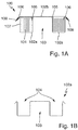
- FIG. 1A an embodiment of an electrochemical cell 100 according to the invention is shown (schematic cross-sectional representation).
- This comprises an annular electrode composite body 101 and a housing 102 consisting of the housing parts 102a and 102b.
- the housing parts 102a and 102b are additionally shown separately ( Figs. 1B and 1C , schematic cross-sectional representation).
- Figs. 1D and 1E schematic cross-sectional view, section through line S
- the housing part 102a including an electrode composite body 101 inserted therein.
- the annular electrode composite body 101 is a lithium ion cell impregnated with an organic electrolyte.
- the electrode composite body 101 is in the form of a hollow-cylindrical winding formed of electrode strips and at least one separator strip whose end faces 101a and 101b are formed by the longitudinal edges of the electrode strips.
- the housing parts 102a and 102b each consist of a PEEK film with a thickness of between 100 and 150 ⁇ m.
- the housing part 102a has two recesses formed by deep drawing, a central cylindrical recess 103 and an outer hollow cylindrical recess 104.
- the housing part 102b is plate-shaped.
- the housing parts 102a and 102b are connected to each other via the two annular welds 105 and 106. Together, they enclose the annular space 107 in which the electrode composite body 101 is enclosed liquid-tight. The interior 107 is in turn arranged around the recess 103 around.
- the electrode composite body 101 includes two current collectors 108 and 109 electrically connected to one of the positive and negative electrodes of the electrode composite body 101.
- the current conductors 108 and 109 are guided between the two housing parts 102a and 102b through out of the interior of the housing 102 to the outside.
Landscapes
- Chemical & Material Sciences (AREA)
- Chemical Kinetics & Catalysis (AREA)
- Electrochemistry (AREA)
- General Chemical & Material Sciences (AREA)
- Engineering & Computer Science (AREA)
- Manufacturing & Machinery (AREA)
- Materials Engineering (AREA)
- Inorganic Chemistry (AREA)
- Health & Medical Sciences (AREA)
- Medicinal Chemistry (AREA)
- Polymers & Plastics (AREA)
- Organic Chemistry (AREA)
- Secondary Cells (AREA)
- Sealing Battery Cases Or Jackets (AREA)
Abstract
Description
- Die nachfolgend beschriebene Erfindung betrifft eine elektrochemische Zelle.
- Besonders bekannte Ausführungsformen elektrochemischer Zellen sind Knopf- und Rundzellen. Knopfzellen weisen meist ein zylindrisches Gehäuse auf, dessen Höhe gleich seinem Durchmesser oder kleiner als dieser ist. Bei Rundzellen ist das Gehäuse ebenfalls zylindrisch ausgebildet, allerdings überschreitet seine Höhe seinen Durchmesser.
- In den Gehäusen können jeweils sehr unterschiedliche elektrochemische Systeme enthalten sein. Sehr verbreitet sind Zellen auf Basis von Zink/Luft, Zink/MnO2 und Nickel/Zink. Auch sekundäre (wiederaufladbare) Systeme sind sehr verbreitet. Beispiele hierfür sind Nickel/Metallhydrid-Zellen, Nickel/Cadmium-Zellen und Lithium-Ionen-Zellen.
- Das zylindrische Gehäuse von Rund- und Knopfzellen besteht klassisch in aller Regel aus zwei festen, meist metallischen Gehäuseteilen, zwischen denen eine elektrisch isolierende Dichtung angeordnet ist. Eines der Gehäuseteile steht in elektrischer Verbindung mit der positiven Elektrode und ist entsprechend positiv gepolt. Das andere steht in elektrischer Verbindung mit der negativen Elektrode und ist entsprechend negativ gepolt. Die Dichtung soll einen elektrischen Kontakt zwischen den entgegengesetzt gepolten Gehäuseteilen unterbinden. Darüber hinaus soll sie einem Entweichen und einem Eindringen von Flüssigkeit und Feuchtigkeit aus dem und in das Gehäuse entgegenwirken.
- Die Verwendung metallischer Gehäuse ist mit mancherlei Nachteilen verbunden. Ihre Herstellung erfolgt mittels eines aufwendigen Tiefziehverfahrens und ein korrosiver Angriff auf das Gehäuse durch den Elektrolyten oder durch im Lade- und Entladebetrieb gebildete sonstige korrosive Substanzen kann trotz gezielter Vorkehrungen niemals gänzlich ausgeschlossen werden.
- Der vorliegenden Erfindung lag die Aufgabe zugrunde, Knopf- und Rundzellen mit einem Gehäuse bereitzustellen, das die erwähnten Nachteile nicht aufweist.
- Die gestellte Aufgabe wird durch die elektrochemische Zelle mit den Merkmalen des Anspruchs 1 gelöst. Bevorzugte Ausführungsformen der erfindungsgemäßen Zelle sind in den abhängigen Ansprüchen 2 bis 7 angegeben. Der Wortlaut sämtlicher Ansprüche wird hiermit durch Bezugnahme zum Inhalt der vorliegenden Beschreibung gemacht.
- Eine elektrochemische Zelle gemäß der vorliegenden Erfindung zeichnet sich stets durch die folgenden Merkmale aus:
- Sie umfasst einen Elektrodenverbundkörper mit mindestens einer positiven und mindestens einer negativen Elektrode: In einem solchen Verbundkörper sind die mindestens eine positive Elektrode und die mindestens eine negative Elektrode fest miteinander verbunden, meist über Lamination oder Verklebung. Zwischen entgegensetzt gepolten Elektroden ist meist ein Separator angeordnet, bei dem es sich um eine poröse Kunststofffolie, beispielsweise aus einem Polyolefin, handeln kann.
Gewickelte Elektrodenverbundkörper sind aus dem Stand der Technik bekannt. Knopfzellen mit gewickelten Elektrodenverbundkörper sind beispielsweise in derWO 2010/146154 A2 und in derWO 2010/089152 A1 beschrieben. Die in diesen Dokumenten beschriebenen Elektrodenverbundkörper können auch für eine erfindungsgemäße Zelle eingesetzt werden.
Zur Herstellung solcher gewickelter Elektrodenverbundkörper wird in einem ersten Schritt eine bandförmige Einzelzelle hergestellt. Hierzu werden bandförmige positive und bandförmige negative Elektroden miteinander sowie mit einem oder mehreren bandförmigen Separatoren kombiniert. Die Elektroden können beispielsweise auf gegenüberliegende Seiten eines Separators laminiert werden. Die so hergestellte bandförmige Einzelzelle wird dann einer Wickelvorrichtung zugeführt und in dieser zu den gewickelten Elektrodenverbundkörper verarbeitet. Hierzu wird die Einzelzelle üblicherweise auf einen Wickeldorn oder einen Wickelkern aufgewickelt. Nach einer meist vordefinierten Anzahl von Windungen (unter einer Windung wird hierbei jeder vollständige Umlauf des Verbundes um den Wickeldorn oder Wickelkern verstanden) wird der Wickelvorgang abgebrochen. Der gebildete gewickelte Verbundkörper wird beispielsweise mittels eines Schneid- oder Stanzwerkzeugs von dem unmittelbar nachfolgenden, noch nicht gewickelten Abschnitt der Einzelzelle abgetrennt. - Der Elektrodenverbundkörper ist mit einem Elektrolyten getränkt: Die Wahl des Elektrolyten hängt davon ab, welches elektrochemische System für die Zelle gewählt wird. Handelt es sich bei der erfindungsgemäßen Zelle um eine Nickel/Metallhydrid-Zelle, so ist der Elektrolyt eine Lauge. Handelt es sich bei der Zelle um eine Lithium-Ionen-Zelle, so setzt sich der Elektrolyt in der Regel aus einer Mischung organischer Carbonate zusammen, in welcher ein Lithium-Leitsalz gelöst ist.
- Sie umfasst ein Gehäuse mit einem flüssigkeitsdicht ausgebildeten Innenraum: Wie bei klassischen Zellen besteht die Primärfunktion des Gehäuses darin, einem Entweichen von Flüssigkeit (Elektrolyt) und einem Eindringen von Feuchtigkeit aus dem und in das Gehäuse entgegenwirken.
- Der mit dem Elektrolyten getränkte Elektrodenverbundkörper ist in dem Innenraum angeordnet: Ziel ist in aller Regel, dass der Elektrodenverbundkörper den Innenraum möglichst effizient ausfüllt. Ein Totvolumen im Innenraum wirkt sich negativ auf die Energiedichte aus.
- Besonders zeichnet sich die erfindungsgemäße Zelle dadurch aus, dass das Gehäuse aus PEK (Polyetherketon) besteht.
- Bei Polyetherketonen handelt es sich bekanntlich um hochtemperaturbeständige thermoplastische Kunststoffe. Die gebräuchlichsten Polyetherketone sind Polyaryletherketone (kurz: PAEK).
- Zu den bekanntesten und wichtigsten Vertretern von PEK zählt PEEK (Polyetheretherketon). Besonders bevorzugt besteht auch das Gehäuse der erfindungsgemäßen Zelle aus PEEK.
- Die Schmelztemperatur von PEEK liegt bei ca. 335 °C bis 345 °C. Es existieren diverse Abkömmlinge (z.B. PEEEK (Poly(etheretheretherketon)) und PEKK (Poly(etherketonketon))), welche geringfügig andere Schmelzpunkte aufweisen (z. B. PEKK ca. 391 °C oder PEEEK ca. 324 °C). Alle diese Abkömmlinge sind als Gehäusematerialien für die erfindungsgemäße Zelle geeignet.
- Polyetherketone sind gegenüber fast allen organischen und anorganischen Chemikalien beständig. Empfindlich sind sie lediglich gegenüber UV-Strahlung sowie gegenüber stark sauren und oxidierenden Bedingungen, wie sie in der Regel in Batterien jedoch nicht anzutreffen sind.
- Die Verwendung von PEK als Gehäusematerial bringt diverse Vorteile mit sich. PEK lässt sich als Thermoplast sehr viel einfacher verarbeiten und Umformen als metallische Materialien. Gegenüber in elektrochemischen Zellen übliche korrosive Substanzen ist es weitestgehend inert. Als elektrischer Isolator minimiert es die Möglichkeiten von Kurzschlüssen über das Gehäuse. Darüber hinaus weist es eine sehr viel niedrigere Dichte als metallische Gehäusematerialien auf. Bei gleicher Gehäusedicke ergeben sich durch die Verwendung von PEK. deutliche Gewichtsvorteile.
- Es ist bevorzugt, dass sich die erfindungsgemäße Zelle durch mindestens eines der folgenden zusätzlichen Merkmale auszeichnet:
- In bevorzugten Ausführungsformen umfasst das Gehäuse zwei Gehäuseteile, die zusammen den Innenraum des Gehäuses ausbilden.
Die zwei Gehäuseteile bestehen bevorzugt aus PEEK-Folien. Diese weisen bevorzugt eine Dicke im Bereich von 50 µm bis 500 µm auf. Innerhalb dieses Bereiches ist eine Dicke im Bereich von 100 µm bis 300 µm weiter bevorzugt. - Die Gehäuseteile können mittels eines Klebers oder aber durch Verschweißung miteinander verbunden werden. Entsprechend sind die Gehäuseteile in bevorzugten Ausführungsformen über mindestens eine Schweiß- oder Klebenaht miteinander verbunden.
Eine Verbindung der Gehäuseteile durch Verschweißung ist grundsätzlich bevorzugt. Gehäuseteile, insbesondere Gehäusefolien, aus PEK lassen sich problemlos miteinander verschweißen, beispielsweise mittels eines Lasers.
Thermoplaste wie PEK absorbieren nur einen geringen Anteil der Laserstrahlung von Festkörperlasern in ihren üblichen Wellenlängenbereichen zwischen 800 bis 1100 nm. Damit diese Thermoplaste durch die Laserstrahlung effizient aufgeschmolzen und verschweißt werden können, können ihnen Additive zugesetzt werden, die ihre Absorptionseigenschaften verbessern. Geeignet sind hierfür alle anorganischen oder organischen Farbpigmente, die in dem genannten Wellenlängenbereich die Strahlung von Festkörperlasern absorbieren, beispielsweise Russ.
Das Verkleben der Gehäuseteile kann beispielsweise mittels eines Schmelzklebers oder eines chemisch abbindenden Klebstoffes erfolgen. Geeignet sind beispielsweise Polyimidklebebänder, Polyethylen- oder Polypropylen-Siegelfolien, Epoxidharz oder Polyurethan. - In weiteren bevorzugten Ausführungsformen der erfindungsgemäßen Zelle umfasst der Elektrodenverbundkörper
- mindestens einen Stromableiter, der elektrisch mit der mindestens einen positiven Elektrode des Elektrodenverbundkörpers verbunden ist
und/oder - mindestens einen Stromableiter, der elektrisch mit der mindestens einen negativen Elektrode des Elektrodenverbundkörpers verbunden ist.
- Bevorzugt sind der oder die Stromableiter sind aus dem Innenraum des Gehäuses nach außen geführt, insbesondere zwischen den zwei Gehäuseteilen.
- In besonders bevorzugten Ausführungsformen weist das Gehäuse mindestens zwei räumlich voneinander getrennte Schweiß- oder Klebenähte auf, wobei es bevorzugt ist, dass die Schweiß- oder Klebenähte jeweils einen ringförmigen Verlauf aufweisen.
- Dies ist insbesondere dann der Fall, wenn die erfindungsgemäße Zelle mindestens eines der folgenden zusätzlichen Merkmale aufweist:
- Wenn der oben beschriebene Elektrodenverbundkörper ringförmig ausgebildet ist.
- Wenn der flüssigkeitsdicht ausgebildete Innenraum, ringförmig ausgebildet und um eine zentrale Durchbrechung oder Ausnehmung herum angeordnet ist.
- Wenn der ringförmige Elektrodenverbundkörper in dem ringförmigen Innenraum angeordnet ist.
- Gehäuse von klassischen Rund- und Knopfzellen sind zylindrisch ausgebildet. Eine zentrale Durchbrechung oder Ausnehmung weisen sie nicht auf.
- Wie eingangs beschrieben wurde, besteht das zylindrische Gehäuse von Rund- und Knopfzellen klassisch in aller Regel aus zwei festen, meist metallischen Gehäuseteilen, zwischen denen eine elektrisch isolierende Dichtung angeordnet ist. Diese Zellen weisen stets genau einen Dichtbereich auf. Anders verhält sich dies bei der letztgenannten Ausführungsform erfindungsgemäßer Zellen. Die Anwesenheit der zentralen Durchbrechung oder der Ausnehmung bedingt, dass diese in der Regel zwei oder mehr Dichtbereiche aufweisen. Gegebenenfalls wird somit auch mehr als eine Dichtung benötigt, um die erfindungsgemäße Zelle abzudichten.
- Das Gehäuse der erfindungsgemäßen Zelle weist in allen Ausführungsformen mit der zentralen Durchbrechung oder Ausnehmung entweder die Durchbrechung oder die Ausnehmung auf. Die zentrale Durchbrechung ist stets durchgängig ausgebildet, sie durchdringt das Gehäuse somit von einer Seite zu einer anderen Seite und ist entsprechend von zwei Seiten des Gehäuses aus zugänglich. Die Ausnehmung hingegen ist nicht durchgängig ausgebildet. Sie ist lediglich von einer Seite des Gehäuses aus zugänglich.
- In besonders bevorzugten Ausführungsformen einer erfindungsgemäßen Zelle weist diese mindestens eines der folgenden zusätzlichen Merkmale auf:
- Das Gehäuse ist als Hohlzylinder ausgebildet.
- Die zentrale Durchbrechung oder die Ausnehmung weist eine zylindrische Geometrie auf.
- Das Gehäuse weist zwei ringkreisförmige, voneinander beabstandete und zueinander parallele Gehäuseböden sowie einen die Gehäuseböden verbindenden ringförmigen inneren Gehäusemantel und einen die Gehäuseböden verbindenden ringförmigen äußeren Gehäusemantel auf, wobei jeder der Gehäusemäntel und jeder der Gehäuseböden jeweils eine in den Innenraum weisende Innenseite und eine in eine entgegengesetzte Richtung weisende Außenseite hat.
- Der Elektrodenverbundkörper liegt als aus Elektrodenbändern und mindestens einem Separatorband gebildeter hohlzylindrischer Wickel vor, dessen Stirnseiten von den Längsrändern der Elektrodenbänder gebildet werden und in dessen Zentrum sich ein axialer Hohlraum mit Öffnungen im Zentrum der Stirnseiten befindet.
- Um eine optimale Kapazitätsausnutzung zu erzielen, ist es zweckmäßig, die geometrischen Merkmale des ringförmigen Elektrodenverbundkörpers und des ringförmigen, flüssigkeitsdichten Gehäuses möglichst gut aufeinander abzustimmen. Bei Elektrodenverbundkörpern wie beispielsweise den in Fig. 3a und Fig. 3b der
WO 2010/089152 A1 beschriebenen handelt es sich nahezu um perfekte Hohlzylinder. Diese können das Volumen des ringförmigen Innenraums am besten ausnutzen, wenn dieser ebenfalls die Form eines Hohlzylinders aufweist. - Die Durchbrechung ist bevorzugt als durchgängiges, zylindrisches Loch ausgebildet. Die Ausnehmung ist bevorzugt als zylindrisches Loch ausgebildet, das auf einer Seite verschlossen ist.
- Eine erfindungsgemäße Zelle ist in bevorzugten Ausführungsformen durch mindestens eines der folgenden zusätzlichen Merkmale gekennzeichnet:
- Die Zelle ist eine Lithium-Ionen-Zelle, insbesondere eine sekundäre Lithium-Ionen-Zelle.
- Mindestens eine der Elektroden des Elektrodenverbundkörpers ist eine Lithium-interkalierende Elektrode.
- Der Elektrodenverbundkörper ist mit einem organischen Elektrolyten mit einem darin gelösten Lithium-Leitsalz getränkt.
- Die Elektroden einer Lithium-Ionen-Zelle umfassen üblicherweise elektrochemisch aktive Komponenten und elektrochemisch inaktive Komponenten.
- Als elektrochemisch aktive Komponenten (oft auch als Aktivmaterialien bezeichnet) kommen für sekundäre Lithium-Ionen-Systeme sämtliche Materialien in Frage, die Lithium-Ionen aufnehmen und wieder abgeben können. Stand der Technik sind diesbezüglich für die negative Elektrode insbesondere Materialien auf Kohlenstoffbasis wie graphitischer Kohlenstoff oder zur Interkalation von Lithium befähigte nichtgraphitische Kohlenstoffmaterialien. Weiterhin können auch metallische und halbmetallische Materialien zum Einsatz kommen, die mit Lithium legierbar sind, oder Komposite aus solchen Materialien mit kohlenstoffbasierten Materialien. Für die positive Elektrode kommen insbesondere Lithium-Metalloxid-Verbindungen und Lithium-Metallphosphat-Verbindungen wie LiCoO2 und LiFePO4 in Frage.
- Als elektrochemisch inaktive Komponenten sind an erster Stelle Elektrodenbinder und Stromkollektoren zu nennen. Letztere dienen dazu, die elektrochemisch aktiven Komponenten möglichst großflächig elektrisch zu kontaktieren. Sie bestehen üblicherweise aus flächigen Metallsubstraten, beispielsweise aus Metallfolien oder einem Metallschaum oder einem metallisierten Vlies. Die Elektrodenbinder gewährleisten die mechanische Stabilität der Elektroden und sorgen für die Kontaktierung der Partikel aus elektrochemisch aktivem Material untereinander sowie zum Stromkollektor. Weiterhin fallen unter den Begriff insbesondere auch Leitmittel, also beispielsweise Ruß.
- Die Zu- und Ableitung von Elektronen zu und aus den Elektroden des Elektrodenverbundkörpers erfolgt meist über Ableiterfahnen, die z.B. stirnseitig aus dem gebildeten gewickelten Verbundkörper herausragen können. Die Ableiterfahnen sind elektrisch an die Stromkollektoren angebunden oder ein Teil derselben.
- Die erfindungsgemäße elektrochemische Zelle unterliegt grundsätzlich keiner Einschränkung hinsichtlich ihrer Größe, einschließlich der Verhältnisse der Durchmesser (Außendurchmesser / Innendurchmesser) oder ihrer Höhe. In einigen Ausführungsformen, in denen das Gehäuse als Hohlzylinder ausgebildet ist, ist es allerdings bevorzugt, dass ihre Höhe ihren Außendurchmesser maximal um den Faktor 2 überschreitet. In einer Weiterbildung ist das Verhältnis Höhe / Außendurchmesser ≤ 1.
- Weitere Merkmale der Erfindung sowie aus der Erfindung resultierende Vorteile ergeben sich aus den Zeichnungen sowie aus der nachfolgenden Beschreibung der Zeichnungen. Die nachfolgend beschriebenen Ausführungsformen dienen lediglich zur Erläuterung und zum besseren Verständnis der Erfindung und sind in keiner Weise einschränkend zu verstehen.
- In
Fig. 1A ist eine Ausführungsform einer erfindungsgemäßen elektrochemischen Zelle 100 dargestellt (schematische Querschnittsdarstellung). Diese umfasst einen ringförmigen Elektrodenverbundkörper 101 sowie ein Gehäuse 102 bestehend aus den Gehäuseteilen 102a und 102b. Die Gehäuseteile 102a und 102b sind zusätzlich separat dargestellt (Figs. 1B und1C , schematische Querschnittsdarstellung). Darüber hinaus ist in denFiguren 1D (schematische Darstellung, Draufsicht von oben) und 1E (schematische Querschnittsdarstellung, Schnitt durch Linie S) das Gehäuseteil 102a samt einem darin eingesetzten Elektrodenverbundkörper 101 dargestellt. - Bei dem ringförmigen Elektrodenverbundkörper 101 handelt es sich um eine Lithium-Ionen-Zelle, die mit einem organischen Elektrolyten getränkt ist. Der Elektrodenverbundkörper 101 liegt als aus Elektrodenbändern und mindestens einem Separatorband gebildeter hohlzylindrischer Wickel vor, dessen Stirnseiten 101a und 101b von den Längsrändern der Elektrodenbänder gebildet werden.
- Die Gehäuseteile 102a und 102b bestehen jeweils aus einer PEEK-Folie mit einer Dicke zwischen 100 und 150 µm. Das Gehäuseteil 102a weist zwei durch Tiefziehen gebildete Ausnehmungen auf, eine zentrale zylindrische Ausnehmung 103 und eine außenliegende hohlzylindrische Ausnehmung 104. Das Gehäuseteil 102b ist tellerförmig ausgebildet.
- Die Gehäuseteile 102a und 102b sind über die beiden ringförmigen Schweißnähte 105 und 106 miteinander verbunden. Sie schließen gemeinsam den ringförmigen Innenraum 107 ein, in dem der Elektrodenverbundkörper 101 flüssigkeitsdicht eingeschlossen ist. Der Innenraum 107 ist wiederum um die Ausnehmung 103 herum angeordnet.
- Der Elektrodenverbundkörper 101 umfasst zwei Stromableiter 108 und 109, die elektrisch mit der einen positiven und einer negativen Elektrode des Elektrodenverbundkörpers 101 verbunden sind. Die Stromableiter 108 und 109 sind zwischen den zwei Gehäuseteilen 102a und 102b hindurch aus dem Innenraum des Gehäuses 102 nach außen geführt.
Claims (7)
- Elektrochemische Zelle mit den folgenden Merkmalen:a. Sie umfasst einen Elektrodenverbundkörper mit mindestens einer positiven und mindestens einer negativen Elektrode.b. Der Elektrodenverbundkörper ist mit einem Elektrolyten getränkt.c. Sie umfasst ein Gehäuse mit einem flüssigkeitsdicht ausgebildeten Innenraum.d. Der mit dem Elektrolyten getränkte Elektrodenverbundkörper ist in dem Innenraum angeordnet.e. Das Gehäuse besteht aus PEK.
- Zelle nach Anspruch 1, gekennzeichnet durch mindestens eines der folgenden zusätzlichen Merkmale:a. Das Gehäuse umfasst zwei Gehäuseteile, die zusammen den Innenraum des Gehäuses ausbilden.b. Die zwei Gehäuseteile bestehen aus PEK-Folien, die bevorzugt eine Dicke im Bereich von 50 µm bis 500 µm aufweisen.c. Die Gehäuseteile sind über mindestens eine Schweiß- oder Klebenaht miteinander verbunden.
- Zelle nach Anspruch 1 oder nach Anspruch 2, gekennzeichnet durch mindestens eines der folgenden zusätzlichen Merkmale:a. Der Elektrodenverbundkörper umfasst mindestens einen Stromableiter, der elektrisch mit der mindestens einen positiven Elektrode des Elektrodenverbundkörpers verbunden ist.b. Der Elektrodenverbundkörper umfasst mindestens einen Stromableiter, der elektrisch mit der mindestens einen negativen Elektrode des Elektrodenverbundkörpers verbunden ist.c. Der oder die Stromableiter sind aus dem Innenraum des Gehäuses nach außen geführt, insbesondere zwischen den zwei Gehäuseteilen.
- Zelle nach einem der vorhergehenden Ansprüche, gekennzeichnet durch mindestens eines der folgenden zusätzlichen Merkmale:a. Das Gehäuse weist mindestens zwei räumlich voneinander getrennte Schweiß- oder Klebenähte auf.b. Die Schweiß- oder Klebenähte weisen jeweils einen ringförmigen Verlauf auf.
- Zelle nach einem der vorhergehenden Ansprüche, gekennzeichnet durch mindestens eines der folgenden zusätzlichen Merkmale:a. Der Elektrodenverbundkörper ist ringförmig ausgebildet.b. Der Innenraum ist ringförmig ausgebildet und um eine zentrale Durchbrechung oder Ausnehmung herum angeordnet.c. Der ringförmige Elektrodenverbundkörper ist in dem ringförmigen Innenraum angeordnet.
- Zelle nach Anspruch 5, gekennzeichnet durch mindestens eines der folgenden zusätzlichen Merkmale:a. Das Gehäuse ist als Hohlzylinder ausgebildet.b. Die zentrale Durchbrechung oder Ausnehmung weist eine zylindrische Geometrie auf.c. Das Gehäuse umfasst zwei ringkreisförmige, voneinander beabstandete und zueinander parallele Gehäuseböden sowie einen die Gehäuseböden verbindenden ringförmigen inneren Gehäusemantel und einen die Gehäuseböden verbindenden ringförmigen äußeren Gehäusemantel, wobei jeder der Gehäusemäntel und jeder der Gehäuseböden jeweils eine in den Innenraum weisende Innenseite und eine in eine entgegengesetzte Richtung weisende Außenseite aufweisen.d. Der Elektrodenverbundkörper liegt als aus Elektrodenbändern und mindestens einem Separatorband gebildeter hohlzylindrischer Wickel vor, dessen Stirnseiten von den Längsrändern der Elektrodenbänder gebildet werden und in dessen Zentrum sich ein axialer Hohlraum mit Öffnungen im Zentrum der Stirnseiten befindet.
- Zelle nach einem der vorhergehenden Ansprüche, gekennzeichnet durch mindestens eines der folgenden zusätzlichen Merkmale:a. Die Zelle ist eine Lithium-Ionen-Zelle.b. Mindestens eine der Elektroden des Elektrodenverbundkörpers ist eine Lithium-interkalierende Elektrode.c. Der Elektrodenverbundkörper ist mit einem organischen Elektrolyten mit einem darin gelösten Lithium-Leitsalz getränkt.
Priority Applications (3)
| Application Number | Priority Date | Filing Date | Title |
|---|---|---|---|
| EP16181222.7A EP3276700B1 (de) | 2016-07-26 | 2016-07-26 | Elektrochemische zelle |
| US15/623,438 US10573924B2 (en) | 2016-07-26 | 2017-06-15 | Electrochemical cell |
| CN201710617186.9A CN107658392A (zh) | 2016-07-26 | 2017-07-26 | 电化学电池 |
Applications Claiming Priority (1)
| Application Number | Priority Date | Filing Date | Title |
|---|---|---|---|
| EP16181222.7A EP3276700B1 (de) | 2016-07-26 | 2016-07-26 | Elektrochemische zelle |
Publications (2)
| Publication Number | Publication Date |
|---|---|
| EP3276700A1 true EP3276700A1 (de) | 2018-01-31 |
| EP3276700B1 EP3276700B1 (de) | 2023-03-01 |
Family
ID=56550774
Family Applications (1)
| Application Number | Title | Priority Date | Filing Date |
|---|---|---|---|
| EP16181222.7A Active EP3276700B1 (de) | 2016-07-26 | 2016-07-26 | Elektrochemische zelle |
Country Status (3)
| Country | Link |
|---|---|
| US (1) | US10573924B2 (de) |
| EP (1) | EP3276700B1 (de) |
| CN (1) | CN107658392A (de) |
Families Citing this family (1)
| Publication number | Priority date | Publication date | Assignee | Title |
|---|---|---|---|---|
| EP3276701A1 (de) * | 2016-07-26 | 2018-01-31 | VARTA Microbattery GmbH | Elektrochemische zelle und vorrichtung mit der zelle |
Citations (7)
| Publication number | Priority date | Publication date | Assignee | Title |
|---|---|---|---|---|
| JP2004006157A (ja) * | 2002-05-31 | 2004-01-08 | Sanyo Electric Co Ltd | 電池パックの製造方法と電池パック |
| JP2010113963A (ja) * | 2008-11-06 | 2010-05-20 | Toyota Central R&D Labs Inc | 水系リチウムイオン二次電池 |
| WO2010089152A1 (de) | 2009-02-09 | 2010-08-12 | Varta Microbattery Gmbh | Knopfzellen und verfahren zu ihrer herstellung |
| US20100279162A1 (en) * | 2008-01-17 | 2010-11-04 | Kyung Sang Chun | Electric energy storage device and method of manufacturing the same |
| WO2010146154A2 (de) | 2009-06-18 | 2010-12-23 | Varta Microbattery Gmbh | Knopfzelle mit wickelelektrode und verfahren zu ihrer herstellung |
| EP2367218A1 (de) * | 2010-03-09 | 2011-09-21 | Samsung SDI Co., Ltd. | Sekundärbatterie |
| US20140120413A1 (en) * | 2012-10-31 | 2014-05-01 | Medtronic, Inc. | Electrochemical device and method for assembling an electrochemical device |
Family Cites Families (12)
| Publication number | Priority date | Publication date | Assignee | Title |
|---|---|---|---|---|
| US8394522B2 (en) * | 2002-08-09 | 2013-03-12 | Infinite Power Solutions, Inc. | Robust metal film encapsulation |
| KR100696809B1 (ko) * | 2004-09-22 | 2007-03-19 | 삼성에스디아이 주식회사 | 리튬 이차 전지 |
| CN1945890B (zh) | 2006-10-25 | 2010-05-12 | 上海万宏动力能源有限公司 | 蓄电池、蓄电池组及它们的制作方法 |
| CN201918433U (zh) | 2010-03-25 | 2011-08-03 | 江西凯源科技有限公司 | 一种环形电池 |
| WO2013079085A1 (en) * | 2011-11-28 | 2013-06-06 | Zhejiang Narada Power Source Co. Ltd. | Case system, battery and battery rack with improved stacking |
| GB2502977B (en) * | 2012-06-11 | 2015-07-15 | Jaguar Land Rover Ltd | A vehicle battery pack, a system for cooling a battery pack and a cooling plate for use in the system |
| CN104781979B (zh) * | 2012-11-12 | 2017-03-08 | 丰田自动车株式会社 | 非水电解质二次电池 |
| KR20150010481A (ko) * | 2013-07-19 | 2015-01-28 | 삼성에스디아이 주식회사 | 파우치 전지 및 그의 제조 방법 |
| US10553854B2 (en) * | 2013-09-26 | 2020-02-04 | Semiconductor Energy Laboratory Co., Ltd. | Secondary battery |
| KR20150049261A (ko) * | 2013-10-29 | 2015-05-08 | 삼성에스디아이 주식회사 | 이차 전지 및 이차 전지의 제조방법 |
| US20150140400A1 (en) * | 2013-11-15 | 2015-05-21 | Semiconductor Energy Laboratory Co., Ltd. | Power storage unit and electronic device including the same |
| US10147556B2 (en) * | 2014-03-31 | 2018-12-04 | Semiconductor Energy Laboratory Co., Ltd. | Power storage device and electronic device |
-
2016
- 2016-07-26 EP EP16181222.7A patent/EP3276700B1/de active Active
-
2017
- 2017-06-15 US US15/623,438 patent/US10573924B2/en active Active
- 2017-07-26 CN CN201710617186.9A patent/CN107658392A/zh active Pending
Patent Citations (7)
| Publication number | Priority date | Publication date | Assignee | Title |
|---|---|---|---|---|
| JP2004006157A (ja) * | 2002-05-31 | 2004-01-08 | Sanyo Electric Co Ltd | 電池パックの製造方法と電池パック |
| US20100279162A1 (en) * | 2008-01-17 | 2010-11-04 | Kyung Sang Chun | Electric energy storage device and method of manufacturing the same |
| JP2010113963A (ja) * | 2008-11-06 | 2010-05-20 | Toyota Central R&D Labs Inc | 水系リチウムイオン二次電池 |
| WO2010089152A1 (de) | 2009-02-09 | 2010-08-12 | Varta Microbattery Gmbh | Knopfzellen und verfahren zu ihrer herstellung |
| WO2010146154A2 (de) | 2009-06-18 | 2010-12-23 | Varta Microbattery Gmbh | Knopfzelle mit wickelelektrode und verfahren zu ihrer herstellung |
| EP2367218A1 (de) * | 2010-03-09 | 2011-09-21 | Samsung SDI Co., Ltd. | Sekundärbatterie |
| US20140120413A1 (en) * | 2012-10-31 | 2014-05-01 | Medtronic, Inc. | Electrochemical device and method for assembling an electrochemical device |
Also Published As
| Publication number | Publication date |
|---|---|
| US20180069261A1 (en) | 2018-03-08 |
| EP3276700B1 (de) | 2023-03-01 |
| US10573924B2 (en) | 2020-02-25 |
| CN107658392A (zh) | 2018-02-02 |
Similar Documents
| Publication | Publication Date | Title |
|---|---|---|
| DE112012006312B4 (de) | Abgedichtete Sekundärbatterie | |
| EP2771922B1 (de) | Knopfzelle mit elektrodenwickel | |
| EP3491682B1 (de) | Elektrochemische zelle und vorrichtung mit der zelle | |
| DE102016217369A1 (de) | Elektrode mit erhöhtem Aktivmaterialanteil | |
| EP3447819B1 (de) | Sekundäre miniaturbatterie mit metallischem gehäuse und verfahren zu ihrer herstellung | |
| DE202017006038U1 (de) | Knopfzelle mit Wickel-Verbundkörper | |
| EP3284119B1 (de) | Batterie mit prismatischem metallgehäuse | |
| DE102018111824B4 (de) | Verfahren zur Herstellung eines gemusterten Elektrodenmaterials | |
| DE102018104635A1 (de) | Geschützte Lithiumelektrodenstruktur für Lithium-Luft-Batterie | |
| EP3745490B1 (de) | Verfahren zur herstellung einer batterie und gemäss dem verfahren hergestellte batterie | |
| EP3151304B1 (de) | Knopfzelle auf lithium-ionen-basis | |
| DE102013204226A1 (de) | Ableiter für einen elektrochemischen Energiespeicher | |
| EP4336632A1 (de) | Energiespeicherelement und verfahren zum herstellen eines solchen energiespeicherelements | |
| EP3276700B1 (de) | Elektrochemische zelle | |
| DE112015003816B4 (de) | Sekundärbatterie | |
| DE102015207069A1 (de) | Batterie mit prismatischem Metallgehäuse | |
| DE212024000248U1 (de) | Batteriezelle, Batterie und stromverbrauchende Vorrichtung | |
| DE102009034674A1 (de) | Lithium-Ionen-Batterie | |
| DE102015209161A1 (de) | Energiespeichervorrichtung | |
| DE112015001519T5 (de) | Stromunterbrechungsvorrichtung und Elektroenergiespeichervorrichtung, die selbige verwendet | |
| EP3605697B1 (de) | Verfahren zur herstellung eines elektroden-separator-wickels, elektroden-separator-wickel und knopfzelle mit einem solchen wickel | |
| DE112012007395B4 (de) | Abgedichtete Sekundärbatterie | |
| EP4465393A1 (de) | Elektrochemische knopfzelle und verfahren zur herstellung | |
| EP3467926B1 (de) | Faserverstärktes kompositmaterial zur verwendung als separator in elektrochemischer festkörperzelle | |
| EP4329083A1 (de) | Elektrochemische energiespeicherzelle und verfahren zur herstellung |
Legal Events
| Date | Code | Title | Description |
|---|---|---|---|
| PUAI | Public reference made under article 153(3) epc to a published international application that has entered the european phase |
Free format text: ORIGINAL CODE: 0009012 |
|
| STAA | Information on the status of an ep patent application or granted ep patent |
Free format text: STATUS: THE APPLICATION HAS BEEN PUBLISHED |
|
| AK | Designated contracting states |
Kind code of ref document: A1 Designated state(s): AL AT BE BG CH CY CZ DE DK EE ES FI FR GB GR HR HU IE IS IT LI LT LU LV MC MK MT NL NO PL PT RO RS SE SI SK SM TR |
|
| AX | Request for extension of the european patent |
Extension state: BA ME |
|
| STAA | Information on the status of an ep patent application or granted ep patent |
Free format text: STATUS: REQUEST FOR EXAMINATION WAS MADE |
|
| 17P | Request for examination filed |
Effective date: 20180704 |
|
| RBV | Designated contracting states (corrected) |
Designated state(s): AL AT BE BG CH CY CZ DE DK EE ES FI FR GB GR HR HU IE IS IT LI LT LU LV MC MK MT NL NO PL PT RO RS SE SI SK SM TR |
|
| STAA | Information on the status of an ep patent application or granted ep patent |
Free format text: STATUS: EXAMINATION IS IN PROGRESS |
|
| 17Q | First examination report despatched |
Effective date: 20190118 |
|
| RAP1 | Party data changed (applicant data changed or rights of an application transferred) |
Owner name: VARTA MICROBATTERY GMBH |
|
| REG | Reference to a national code |
Ref country code: DE Ref legal event code: R079 Ref document number: 502016015612 Country of ref document: DE Free format text: PREVIOUS MAIN CLASS: H01M0002020000 Ipc: H01M0050107000 |
|
| RIC1 | Information provided on ipc code assigned before grant |
Ipc: H01M 10/0587 20100101ALI20220930BHEP Ipc: H01M 10/052 20100101ALI20220930BHEP Ipc: H01M 10/04 20060101ALI20220930BHEP Ipc: H01M 50/133 20210101ALI20220930BHEP Ipc: H01M 50/121 20210101ALI20220930BHEP Ipc: H01M 50/109 20210101ALI20220930BHEP Ipc: H01M 50/107 20210101AFI20220930BHEP |
|
| GRAP | Despatch of communication of intention to grant a patent |
Free format text: ORIGINAL CODE: EPIDOSNIGR1 |
|
| STAA | Information on the status of an ep patent application or granted ep patent |
Free format text: STATUS: GRANT OF PATENT IS INTENDED |
|
| INTG | Intention to grant announced |
Effective date: 20221121 |
|
| GRAS | Grant fee paid |
Free format text: ORIGINAL CODE: EPIDOSNIGR3 |
|
| GRAA | (expected) grant |
Free format text: ORIGINAL CODE: 0009210 |
|
| STAA | Information on the status of an ep patent application or granted ep patent |
Free format text: STATUS: THE PATENT HAS BEEN GRANTED |
|
| AK | Designated contracting states |
Kind code of ref document: B1 Designated state(s): AL AT BE BG CH CY CZ DE DK EE ES FI FR GB GR HR HU IE IS IT LI LT LU LV MC MK MT NL NO PL PT RO RS SE SI SK SM TR |
|
| REG | Reference to a national code |
Ref country code: GB Ref legal event code: FG4D Free format text: NOT ENGLISH |
|
| REG | Reference to a national code |
Ref country code: CH Ref legal event code: EP Ref country code: AT Ref legal event code: REF Ref document number: 1551639 Country of ref document: AT Kind code of ref document: T Effective date: 20230315 |
|
| REG | Reference to a national code |
Ref country code: DE Ref legal event code: R096 Ref document number: 502016015612 Country of ref document: DE |
|
| REG | Reference to a national code |
Ref country code: IE Ref legal event code: FG4D Free format text: LANGUAGE OF EP DOCUMENT: GERMAN |
|
| REG | Reference to a national code |
Ref country code: LT Ref legal event code: MG9D |
|
| REG | Reference to a national code |
Ref country code: NL Ref legal event code: MP Effective date: 20230301 |
|
| P01 | Opt-out of the competence of the unified patent court (upc) registered |
Effective date: 20230526 |
|
| PG25 | Lapsed in a contracting state [announced via postgrant information from national office to epo] |
Ref country code: RS Free format text: LAPSE BECAUSE OF FAILURE TO SUBMIT A TRANSLATION OF THE DESCRIPTION OR TO PAY THE FEE WITHIN THE PRESCRIBED TIME-LIMIT Effective date: 20230301 Ref country code: NO Free format text: LAPSE BECAUSE OF FAILURE TO SUBMIT A TRANSLATION OF THE DESCRIPTION OR TO PAY THE FEE WITHIN THE PRESCRIBED TIME-LIMIT Effective date: 20230601 Ref country code: LV Free format text: LAPSE BECAUSE OF FAILURE TO SUBMIT A TRANSLATION OF THE DESCRIPTION OR TO PAY THE FEE WITHIN THE PRESCRIBED TIME-LIMIT Effective date: 20230301 Ref country code: LT Free format text: LAPSE BECAUSE OF FAILURE TO SUBMIT A TRANSLATION OF THE DESCRIPTION OR TO PAY THE FEE WITHIN THE PRESCRIBED TIME-LIMIT Effective date: 20230301 Ref country code: HR Free format text: LAPSE BECAUSE OF FAILURE TO SUBMIT A TRANSLATION OF THE DESCRIPTION OR TO PAY THE FEE WITHIN THE PRESCRIBED TIME-LIMIT Effective date: 20230301 Ref country code: ES Free format text: LAPSE BECAUSE OF FAILURE TO SUBMIT A TRANSLATION OF THE DESCRIPTION OR TO PAY THE FEE WITHIN THE PRESCRIBED TIME-LIMIT Effective date: 20230301 |
|
| PG25 | Lapsed in a contracting state [announced via postgrant information from national office to epo] |
Ref country code: SE Free format text: LAPSE BECAUSE OF FAILURE TO SUBMIT A TRANSLATION OF THE DESCRIPTION OR TO PAY THE FEE WITHIN THE PRESCRIBED TIME-LIMIT Effective date: 20230301 Ref country code: PL Free format text: LAPSE BECAUSE OF FAILURE TO SUBMIT A TRANSLATION OF THE DESCRIPTION OR TO PAY THE FEE WITHIN THE PRESCRIBED TIME-LIMIT Effective date: 20230301 Ref country code: NL Free format text: LAPSE BECAUSE OF FAILURE TO SUBMIT A TRANSLATION OF THE DESCRIPTION OR TO PAY THE FEE WITHIN THE PRESCRIBED TIME-LIMIT Effective date: 20230301 Ref country code: GR Free format text: LAPSE BECAUSE OF FAILURE TO SUBMIT A TRANSLATION OF THE DESCRIPTION OR TO PAY THE FEE WITHIN THE PRESCRIBED TIME-LIMIT Effective date: 20230602 Ref country code: FI Free format text: LAPSE BECAUSE OF FAILURE TO SUBMIT A TRANSLATION OF THE DESCRIPTION OR TO PAY THE FEE WITHIN THE PRESCRIBED TIME-LIMIT Effective date: 20230301 |
|
| PG25 | Lapsed in a contracting state [announced via postgrant information from national office to epo] |
Ref country code: SM Free format text: LAPSE BECAUSE OF FAILURE TO SUBMIT A TRANSLATION OF THE DESCRIPTION OR TO PAY THE FEE WITHIN THE PRESCRIBED TIME-LIMIT Effective date: 20230301 Ref country code: RO Free format text: LAPSE BECAUSE OF FAILURE TO SUBMIT A TRANSLATION OF THE DESCRIPTION OR TO PAY THE FEE WITHIN THE PRESCRIBED TIME-LIMIT Effective date: 20230301 Ref country code: PT Free format text: LAPSE BECAUSE OF FAILURE TO SUBMIT A TRANSLATION OF THE DESCRIPTION OR TO PAY THE FEE WITHIN THE PRESCRIBED TIME-LIMIT Effective date: 20230703 Ref country code: EE Free format text: LAPSE BECAUSE OF FAILURE TO SUBMIT A TRANSLATION OF THE DESCRIPTION OR TO PAY THE FEE WITHIN THE PRESCRIBED TIME-LIMIT Effective date: 20230301 Ref country code: CZ Free format text: LAPSE BECAUSE OF FAILURE TO SUBMIT A TRANSLATION OF THE DESCRIPTION OR TO PAY THE FEE WITHIN THE PRESCRIBED TIME-LIMIT Effective date: 20230301 |
|
| PG25 | Lapsed in a contracting state [announced via postgrant information from national office to epo] |
Ref country code: SK Free format text: LAPSE BECAUSE OF FAILURE TO SUBMIT A TRANSLATION OF THE DESCRIPTION OR TO PAY THE FEE WITHIN THE PRESCRIBED TIME-LIMIT Effective date: 20230301 Ref country code: IS Free format text: LAPSE BECAUSE OF FAILURE TO SUBMIT A TRANSLATION OF THE DESCRIPTION OR TO PAY THE FEE WITHIN THE PRESCRIBED TIME-LIMIT Effective date: 20230701 |
|
| REG | Reference to a national code |
Ref country code: DE Ref legal event code: R097 Ref document number: 502016015612 Country of ref document: DE |
|
| PLBE | No opposition filed within time limit |
Free format text: ORIGINAL CODE: 0009261 |
|
| STAA | Information on the status of an ep patent application or granted ep patent |
Free format text: STATUS: NO OPPOSITION FILED WITHIN TIME LIMIT |
|
| PG25 | Lapsed in a contracting state [announced via postgrant information from national office to epo] |
Ref country code: SI Free format text: LAPSE BECAUSE OF FAILURE TO SUBMIT A TRANSLATION OF THE DESCRIPTION OR TO PAY THE FEE WITHIN THE PRESCRIBED TIME-LIMIT Effective date: 20230301 Ref country code: DK Free format text: LAPSE BECAUSE OF FAILURE TO SUBMIT A TRANSLATION OF THE DESCRIPTION OR TO PAY THE FEE WITHIN THE PRESCRIBED TIME-LIMIT Effective date: 20230301 |
|
| 26N | No opposition filed |
Effective date: 20231204 |
|
| PG25 | Lapsed in a contracting state [announced via postgrant information from national office to epo] |
Ref country code: MC Free format text: LAPSE BECAUSE OF FAILURE TO SUBMIT A TRANSLATION OF THE DESCRIPTION OR TO PAY THE FEE WITHIN THE PRESCRIBED TIME-LIMIT Effective date: 20230301 |
|
| PG25 | Lapsed in a contracting state [announced via postgrant information from national office to epo] |
Ref country code: MC Free format text: LAPSE BECAUSE OF FAILURE TO SUBMIT A TRANSLATION OF THE DESCRIPTION OR TO PAY THE FEE WITHIN THE PRESCRIBED TIME-LIMIT Effective date: 20230301 |
|
| REG | Reference to a national code |
Ref country code: CH Ref legal event code: PL |
|
| REG | Reference to a national code |
Ref country code: BE Ref legal event code: MM Effective date: 20230731 |
|
| PG25 | Lapsed in a contracting state [announced via postgrant information from national office to epo] |
Ref country code: LU Free format text: LAPSE BECAUSE OF NON-PAYMENT OF DUE FEES Effective date: 20230726 |
|
| PG25 | Lapsed in a contracting state [announced via postgrant information from national office to epo] |
Ref country code: LU Free format text: LAPSE BECAUSE OF NON-PAYMENT OF DUE FEES Effective date: 20230726 |
|
| REG | Reference to a national code |
Ref country code: IE Ref legal event code: MM4A |
|
| PG25 | Lapsed in a contracting state [announced via postgrant information from national office to epo] |
Ref country code: CH Free format text: LAPSE BECAUSE OF NON-PAYMENT OF DUE FEES Effective date: 20230731 |
|
| PG25 | Lapsed in a contracting state [announced via postgrant information from national office to epo] |
Ref country code: IT Free format text: LAPSE BECAUSE OF FAILURE TO SUBMIT A TRANSLATION OF THE DESCRIPTION OR TO PAY THE FEE WITHIN THE PRESCRIBED TIME-LIMIT Effective date: 20230301 Ref country code: BE Free format text: LAPSE BECAUSE OF NON-PAYMENT OF DUE FEES Effective date: 20230731 |
|
| PG25 | Lapsed in a contracting state [announced via postgrant information from national office to epo] |
Ref country code: IE Free format text: LAPSE BECAUSE OF NON-PAYMENT OF DUE FEES Effective date: 20230726 |
|
| PG25 | Lapsed in a contracting state [announced via postgrant information from national office to epo] |
Ref country code: IE Free format text: LAPSE BECAUSE OF NON-PAYMENT OF DUE FEES Effective date: 20230726 |
|
| REG | Reference to a national code |
Ref country code: AT Ref legal event code: MM01 Ref document number: 1551639 Country of ref document: AT Kind code of ref document: T Effective date: 20230726 |
|
| PG25 | Lapsed in a contracting state [announced via postgrant information from national office to epo] |
Ref country code: AT Free format text: LAPSE BECAUSE OF NON-PAYMENT OF DUE FEES Effective date: 20230726 |
|
| PG25 | Lapsed in a contracting state [announced via postgrant information from national office to epo] |
Ref country code: AT Free format text: LAPSE BECAUSE OF NON-PAYMENT OF DUE FEES Effective date: 20230726 |
|
| PG25 | Lapsed in a contracting state [announced via postgrant information from national office to epo] |
Ref country code: BG Free format text: LAPSE BECAUSE OF FAILURE TO SUBMIT A TRANSLATION OF THE DESCRIPTION OR TO PAY THE FEE WITHIN THE PRESCRIBED TIME-LIMIT Effective date: 20230301 |
|
| PG25 | Lapsed in a contracting state [announced via postgrant information from national office to epo] |
Ref country code: BG Free format text: LAPSE BECAUSE OF FAILURE TO SUBMIT A TRANSLATION OF THE DESCRIPTION OR TO PAY THE FEE WITHIN THE PRESCRIBED TIME-LIMIT Effective date: 20230301 |
|
| PG25 | Lapsed in a contracting state [announced via postgrant information from national office to epo] |
Ref country code: CY Free format text: LAPSE BECAUSE OF FAILURE TO SUBMIT A TRANSLATION OF THE DESCRIPTION OR TO PAY THE FEE WITHIN THE PRESCRIBED TIME-LIMIT; INVALID AB INITIO Effective date: 20160726 |
|
| PG25 | Lapsed in a contracting state [announced via postgrant information from national office to epo] |
Ref country code: HU Free format text: LAPSE BECAUSE OF FAILURE TO SUBMIT A TRANSLATION OF THE DESCRIPTION OR TO PAY THE FEE WITHIN THE PRESCRIBED TIME-LIMIT; INVALID AB INITIO Effective date: 20160726 |
|
| PGFP | Annual fee paid to national office [announced via postgrant information from national office to epo] |
Ref country code: DE Payment date: 20250723 Year of fee payment: 10 |
|
| PGFP | Annual fee paid to national office [announced via postgrant information from national office to epo] |
Ref country code: GB Payment date: 20250724 Year of fee payment: 10 |
|
| PGFP | Annual fee paid to national office [announced via postgrant information from national office to epo] |
Ref country code: FR Payment date: 20250723 Year of fee payment: 10 |
|
| PG25 | Lapsed in a contracting state [announced via postgrant information from national office to epo] |
Ref country code: TR Free format text: LAPSE BECAUSE OF FAILURE TO SUBMIT A TRANSLATION OF THE DESCRIPTION OR TO PAY THE FEE WITHIN THE PRESCRIBED TIME-LIMIT Effective date: 20230301 |